Kit 12.0 Soo Line AAR Modified Design Auto Box Cars
8
Introduction ank you for your interest in Resin Car Works and this kit. Resin Car Works is not a business in the traditional sense. Its purpose is to share in the fun of prototype railroad freight car modeling and their operations with others to provide unique and different equipment that isn’t readily available. Several friends assisted with various production phases so it’s not quite a one-man operation. To list a few who helped with the production of this kit I would like to thank: Tom Madden for his casting work; Ken So- roos for the decal artwork (which is taken directly from the prototype cars themselves), car history, and for help with formatting the instructions; and to Eric Hansmann, the keeper of the website and blog. is is a “CRAFTMANS” level resin kit and its construction should not be attempted by anyone who has not built similar types of mod- els or who doesn’t have a knowledge of prototype freight car construc- tion and components. e kit consists of a one piece resin body, floor and detail parts; Plano Models etched ladders; Yarmouth laser-cut wood running board; A-Line stirrups; Tichy AB brake set; assorted wire sizes and grabs; Microscale decals; and the closest Tahoe Models truck type that is available. e modeler is to supply any small styrene bits, couplers, weight and small screws needed to complete the model. and small screws needed to complete the model. Warranty All sales are final. ere will be no exchanges or returns. Resin Car Works will replace any part(s) found to be defective due to manufacturing or ship- ping to the original purchaser within the first 30 days aſter shipment. e damaged part(s) must be sent back with your request for replacement. As these are limited production kits, don’t ask for replacement of parts that you damage or lose aſter the 30-day period. Liability Resin Car works will not be responsible or held liable for any and all personal injury and/or health problems, short and/or long term, that may result from the use and/or misuse of tools, adhesives, materials, castings, paints or any other product(s) used to construct and/or contained in this Kit 12.0 Soo Line AAR Modified Design 50’ Steel Auto Box Cars 1 All Model and Construction Photos by Frank Hodina
Transcript of Kit 12.0 Soo Line AAR Modified Design Auto Box Cars

Introduction
Thank you for your interest in Resin Car Works and this kit. Resin Car Works is not a business in the traditional sense. Its purpose is to share in the fun of prototype railroad freight car modeling and their operations with others to provide unique and different equipment that isn’t readily available. Several friends assisted with various production phases so it’s not quite a one-man operation. To list a few who helped with the production of this kit I would like to thank: Tom Madden for his casting work; Ken So-roos for the decal artwork (which is taken directly from the prototype cars themselves), car history, and for help with formatting the instructions; and to Eric Hansmann, the keeper of the website and blog. This is a “CRAFTMANS” level resin kit and its construction should not be attempted by anyone who has not built similar types of mod-els or who doesn’t have a knowledge of prototype freight car construc-tion and components. The kit consists of a one piece resin body, floor and detail parts; Plano Models etched ladders; Yarmouth laser-cut wood running board; A-Line stirrups; Tichy AB brake set; assorted wire sizes and grabs; Microscale decals; and the closest Tahoe Models truck type that is available. The modeler is to supply any small styrene
bits, couplers, weight and small screws needed to complete the model. and small screws needed to complete the model.
Warranty
All sales are final. There will be no exchanges or returns. Resin Car Works will replace any part(s) found to be defective due to manufacturing or ship-ping to the original purchaser within the first 30 days after shipment. The damaged part(s) must be sent back with your request for replacement. As these are limited production kits, don’t ask for replacement of parts that you damage or lose after the 30-day period.
Liability
Resin Car works will not be responsible or held liable for any and all personal injury and/or health problems, short and/or long term, that may result from the use and/or misuse of tools, adhesives, materials, castings, paints or any other product(s) used to construct and/or contained in this
Kit 12.0 Soo LineAAR Modified Design
50’ Steel Auto Box Cars
1
All Model and Construction Photos by Frank Hodina

kit. This kit contains polyurethane castings. Although non-toxic in their cured state, dust is created during filing, sanding and drilling. Air circula-tion and/or ventilation should be provided. Always work in a well-ventilat-ed room. Wear a dust mask or respirator and safety glasses for protection. Always wash your hands when you’re finished working.
History
The Soo Line and its leased (since 1909) subsidiary Wisconsin Central began their transition to steel boxcars in 1936 with three car types, all from Pullman-Standard. In 1937 and 1939 it received its first 40’ and 50’ double-door boxcars, again from Pullman-Standard. The 50’-0” W.C.-series cars had a 10’-1” inside height and were unusual in that the two doors cov-ered a 12’-6” door opening located nominally at the center of the car side. This configuration was the standard for Soo and W.C. 50’ double-door cars through the 1950s. The second type of Soo and W.C. 50’ double-door boxcars arrived from Pullman-Standard in 1940 and 1942 and are the prototypes for this Resin Car Works model. These 600 cars were built to the 1937 AAR Modified design standard with a 10-5” inside height and 50’-6” inside length. The cars featured Youngstown doors, 5/5 square-corner Dreadnaught ends, and Murphy improved steel roofs. Although designated as automobile cars, the centered 12’-6” door openings were preferred for paper loading from Wis-consin mills, the service for which they were originally purchased. Number series for these cars were: Soo 76000-76198 (even), 100 cars, built 9-40, Lot 5632 WC 175700-175898 (even), 100 cars, built 9-40, Lot 5646 Soo 76200-76398 (even), 100 cars, built 2-42, Lot 5689 WC 175900-176498 (even), 300 cars, built 2-42, Lot 5689 The third type of W.C. 50’ double-door boxcars (350 total) was built/as-sembled by the Soo Line at its North Fond du Lac, WI shops in 1950, 1954 and 1957. These cars were built with underframes and hardware fabricated at NFduL. Sides, R/3/4 Dreadnaught ends, diagonal panel roofs and doors (Youngstown) were sourced from other manufacturers. These cars had 50-6” inside lengths and 10’-6” inside heights.
Construction
It’s recommended that before you start construction that you familiar-ize yourself with the additional information and photos on the Resin Car Works website www.resincarworks.com that pertain to this kit. Especially helpful are a series of prototype drawings that show the placement of the various car parts.
➢ First give the resin parts a good cleaning with Dawn and a toothbrush to remove any mold releasing agents. A light sanding of joints also helps parts to bond.
➢ The cast parts are best attached with ACC. When the term “cement” is used in these instructions, it refers to ACC. ACC is a strong adhesive which dries quickly. It can easily attach a part where it is not supposed to be. It will glue skin. Be careful. Place a few drops on a plate of glass and use a wire or pin to transfer small amounts of ACC to the area to be joined. Always wear safety glasses. ACC debonder is a useful tool for removing smudges of ACC from surfaces where it shouldn’t be. Place a drop on the offending spot and wipe up.
➢ GOO or other such products are not recommended for construction except in small quantities, as they will soften the casting material.
➢ When a measurement is given, it’s in prototype feet and inches.
➢ When the word “scrap” is used, it refers to an item that the modeler is to supply.
2

3
1
1. Body
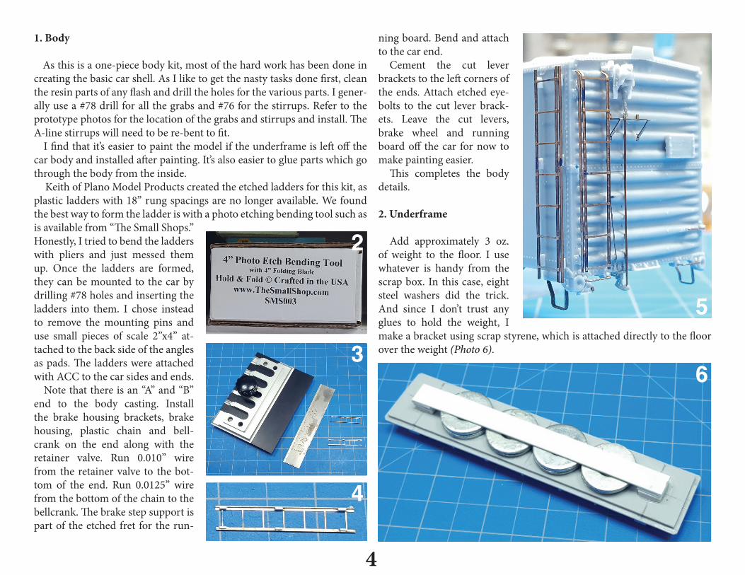
As this is a one-piece body kit, most of the hard work has been done in creating the basic car shell. As I like to get the nasty tasks done first, clean the resin parts of any flash and drill the holes for the various parts. I gener-ally use a #78 drill for all the grabs and #76 for the stirrups. Refer to the prototype photos for the location of the grabs and stirrups and install. The A-line stirrups will need to be re-bent to fit. I find that it’s easier to paint the model if the underframe is left off the car body and installed after painting. It’s also easier to glue parts which go through the body from the inside.
Keith of Plano Model Products created the etched ladders for this kit, as plastic ladders with 18” rung spacings are no longer available. We found the best way to form the ladder is with a photo etching bending tool such as is available from “The Small Shops.” Honestly, I tried to bend the ladders with pliers and just messed them up. Once the ladders are formed, they can be mounted to the car by drilling #78 holes and inserting the ladders into them. I chose instead to remove the mounting pins and use small pieces of scale 2”x4” at-tached to the back side of the angles as pads. The ladders were attached with ACC to the car sides and ends. Note that there is an “A” and “B” end to the body casting. Install the brake housing brackets, brake housing, plastic chain and bell-crank on the end along with the retainer valve. Run 0.010” wire from the retainer valve to the bot-tom of the end. Run 0.0125” wire from the bottom of the chain to the bellcrank. The brake step support is part of the etched fret for the run-
ning board. Bend and attach to the car end.
Cement the cut lever brackets to the left corners of the ends. Attach etched eye-bolts to the cut lever brack-ets. Leave the cut levers, brake wheel and running board off the car for now to make painting easier.
This completes the body details.
2. Underframe
Add approximately 3 oz. of weight to the floor. I use whatever is handy from the scrap box. In this case, eight steel washers did the trick. And since I don’t trust any glues to hold the weight, I make a bracket using scrap styrene, which is attached directly to the floor over the weight (Photo 6).
4
2
3
4
5
6

Attach coupler pockets to the underframe and drill and tap holes for 2-56 truck screws and 1-72 for coupler cover screws. The coupler boxes will accept only Kadee No. 158 semi-scale Whisker couplers.
Refer to the photos (Photos 8, 9, 10, 11) and brake general arrangement to determine the location of the crossties and brake components.
Fit and cement the four bolster covers and the cover plates on the cross-bearers.
Fit and cement the eight crossties to the center sill. The crossties match the tabs on the car side between the bolsters and crossbearers. They are placed with their notches under the centersill flange and with the channels facing outward toward the end of the car (Photo 8).
Drill out all the holes on the brake components needed for piping. The triple valve goes on the pad cast onto the underframe floor. Cement the
brake cylinder bracket on the pads on the center sill and stringer. Cement the brake cylinder to the bracket.
Cement the reservoir to the center crossbearer. Use a piece of scrap etched material to create a bracket for the free end of the brake reservoir.
Now install all the connecting piping using the 0.010” wire. Install brake levers with 0.0125” wire using the Tichy turnbuckles with
one end removed as clevises. Also install the connecting rod from the brake cylinder to the bolster with a small piece of scrap chain at the brake cylinder.
This completes the underframe.
5
7
8
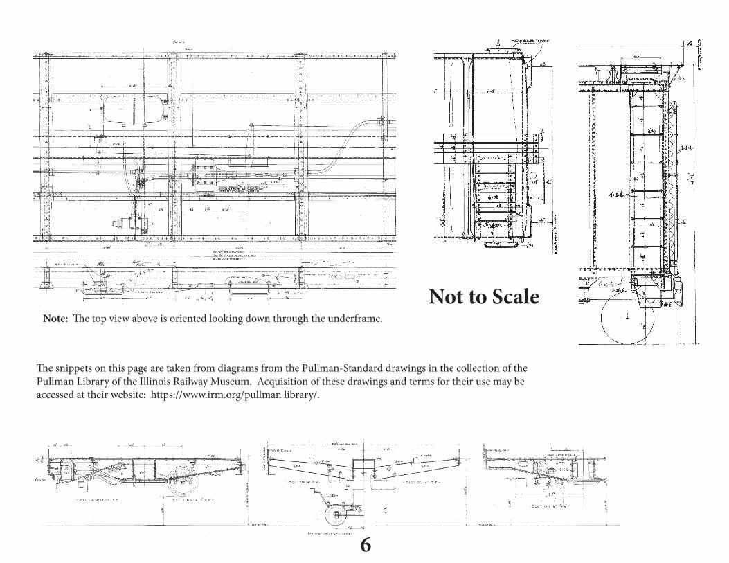
Not to Scale
The snippets on this page are taken from diagrams from the Pullman-Standard drawings in the collection of the Pullman Library of the Illinois Railway Museum. Acquisition of these drawings and terms for their use may be accessed at their website: https://www.irm.org/pullman library/.
Note: The top view above is oriented looking down through the underframe.
6

7
5
9
10
11

8
3. Soo Line Painting and Lettering History
When built, the cars were painted mineral red overall with black ends. The “$-sign” herald had a black background. See the builder’s photo on the following page.
After WWII, new cars and repaints were done in a lighter oxide red. The black background to the “$-sign” herald was no longer used. Black ends lasted until mid-1951. The 4’ block “SOO LINE” was introduced during 1951 and the “$-sign” herald was no longer used on new or repainted 40’ and 50’ steel boxcars.. Note that there are two different “S” characters in-cluded with the block lettering. The one with the slanted middle bar was used from 1951 until 1958. Thereafter, the one with the horizontal middle bar was generally used on new cars and repaints. Beginning in the later 1950s, a more boxcar red color was used on Soo repaints.
3. Painting for This Model
Before painting, wash the car again with Dawn; rinse and let dry. As for the color and types of paint, that’s an individual choice. In this
case, I used Testor’s Model Master British Crimson for the basic body color and Scalecoat I black for the underframe and trucks. For this model I was looking for a car that had been repainted since being built, but hadn’t yet been repainted with the large “SOO LINE” name. My car received mineral red ends. Also for this car I wanted a roof that had “just about” lost all its paint. Prior to painting the body, the roof was given a coat of galvanized paint, which in this case is a 50/50 mix of Testor’s Model Master Aluminum and flat white. When dry the car was given a coat of Testor’s gloss coat for decaling.
4. Final Detailing
Place small amounts of Pliobond on the roof supports. Carefully place the running board on the roof supports, equidistant between ends. Touch the roof supports with small amounts of ACC when the Pliobond is dry to set the running board.
Bend and install the end running board supports between the running board and car end and cement. When dry, trim the running board to match
the support ends.Bend the lateral running board supports and cement to the back side
of the lateral running boards. Using a #78 drill, drill through the wood where the holes are etched in the supports. Now cement the lateral running boards and supports to the car roof. Form 0.0125” wire for the corner grabs and, with the etched eyebolts, cement to the laterals.
Attach the underframe to the body, making sure that that the brake cyl-inder is oriented toward the “B” end. Install the trucks, adjusting the cou-pler height with Kadee fiber washers.
Form cut levers from 0.0125” wire using the prototype photos to deter-mine their shape and attach to the car.
Finish up the model with the lettering scheme of your choice and fol-low by sealing the car with flat glaze. After weathering, the model is ready for the layout. And don’t forget to make the car card for your new piece of freight equipment.
4. A Note on Trucks
We asked Brian Leppart of Tahoe Models which truck fits closest to the ones used on these cars; “Those are ‘self-aligning spring-plankless double-truss’ trucks, just like my #007s but with closer-spaced springs. Tangent makes a somewhat similar double-truss truck with the closer spring spac-ing, but they sit on a spring plate.” So, Tahoe Models #007 Double-Truss sideframes are provided in the kit, as they’re the closest match to the pro-totype’s trucks.