KIP 6000 Service Manaul Ver a.0-1
325
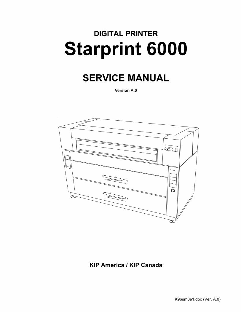
K96sm0e1.doc (Ver. A.0) DIGITAL PRINTER Starprint 6000 SERVICE MANUAL Version A.0 KIP America / KIP Canada
Transcript of KIP 6000 Service Manaul Ver a.0-1
K96sm0e1.doc (Ver. A.0)
DIGITAL PRINTER
Starprint 6000
SERVICE MANUAL
Version A.0
KIP America / KIP Canada
PREFACE This service manual contains the basic information required for carrying out field service to support the product quality and functions of the Starprint 6000 printer. Chapter 1 Introduction : Features, specifications and operation procedure Chapter 2 Installation : Installation place and procedure/Unpacking Chapter 3 Copy Process : Brief explanation of image formation and copy processes Chapter 4 Electrical Systems : Basic principles of electrical system and operation Chapter 5 Mechanical Systems : Mechanical structure, disassembly, assembly, and adjustment
methods Chapter 6 Maintenance/Checking : Periodic replacement parts table, consumables durability yardstick table, periodic service table Chapter 7 Troubleshooting : Procedures and handling against malfunctions and image quality Chapter 8 Service mode : Service Mode Chapter 9 Appendices : Overall timing chart, overall circuit diagram, printed circuit
diagram, etc. Some of the information contained in this manual may be changed by product upgrades etc. Such information will be communicated as engineering notices as necessary. Read this service manual and any engineering notices carefully. A correct understanding of this machine is the only way to develop the skills for maintaining the product quality and functions of this product for a long period of time and the applied capacity for finding the causes of breakdowns.
K96sm1e1.doc (Ver. A.0)
Chapter 1
Introduction Page 1.1 Features 1- 1 1.2 Specifications 1- 2 1.3 Name of Each Part 1- 3 1.3.1 Front view 1- 3 1.3.2 Rear view 1- 4
K96sm1e1.doc (Ver. A.0) 1-1
1.1 Features (1) Starprint 6000 Printer can make a print at a speed of 100mm per second. The maximum print size is 36 inches wide, and the minimum one is 8.5” ( 210mm ).
(2) The print image is produced by the HDP process and a minute monocomponent nonmagnetic toner is utilized.
(3) No toner waste or Drum Cleaning Blades are used.
K96sm1e1.doc (Ver. A.0) 1-2
1.2 Specifications
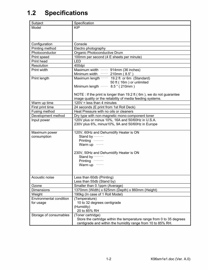
Subject Specification Model KIP
Configuration Console Printing method Electro photography Photoconductor Organic Photoconductive Drum Print speed 100mm per second (4 E sheets per minute) Print head LED Resolution 400dpi Print width Maximum width 914mm (36 inches)
Minimum width 210mm ( 8.5” ) Print length Maximum length 19.2 ft or 6m (Standard)
50 ft ( 16m ) or unlimited Minimum length 8.5 “ ( 210mm ) NOTE : If the print is longer than 19.2 ft ( 6m ), we do not guarantee image quality or the reliability of media feeding systems.
Warm up time 120V = less than 4 minutes First print time 24 seconds (E print from 1st Roll Deck) Fusing method Heat Pressure with no oils or cleaners Development method Dry type with non-magnetic mono-component toner Input power 120V plus or minus 10%, 16A and 50/60Hz in U.S.A.
230V plus 6%, minus10%, 9A and 50/60Hz in Europe
Maximum power consumption
120V, 60Hz and Dehumidify Heater is ON Stand by Printing Warm up 230V, 50Hz and Dehumidify Heater is ON Stand by Printing Warm up
Acoustic noise Less than 60db (Printing) Less than 55db (Stand by)
Ozone Smaller than 0.1ppm (Average) Dimensions 1370mm (Width) x 625mm (Depth) x 860mm (Height) Weight 190kg (In case of 1 Roll Model) Environmental condition for usage
(Temperature) 10 to 32 degrees centigrade (Humidity) 20 to 85% RH
Storage of consumables (Toner cartridge) Store the cartridge within the temperature range from 0 to 35 degrees centigrade and within the humidity range from 10 to 85% RH.
K96sm1e1.doc (Ver. A.0) 1-3
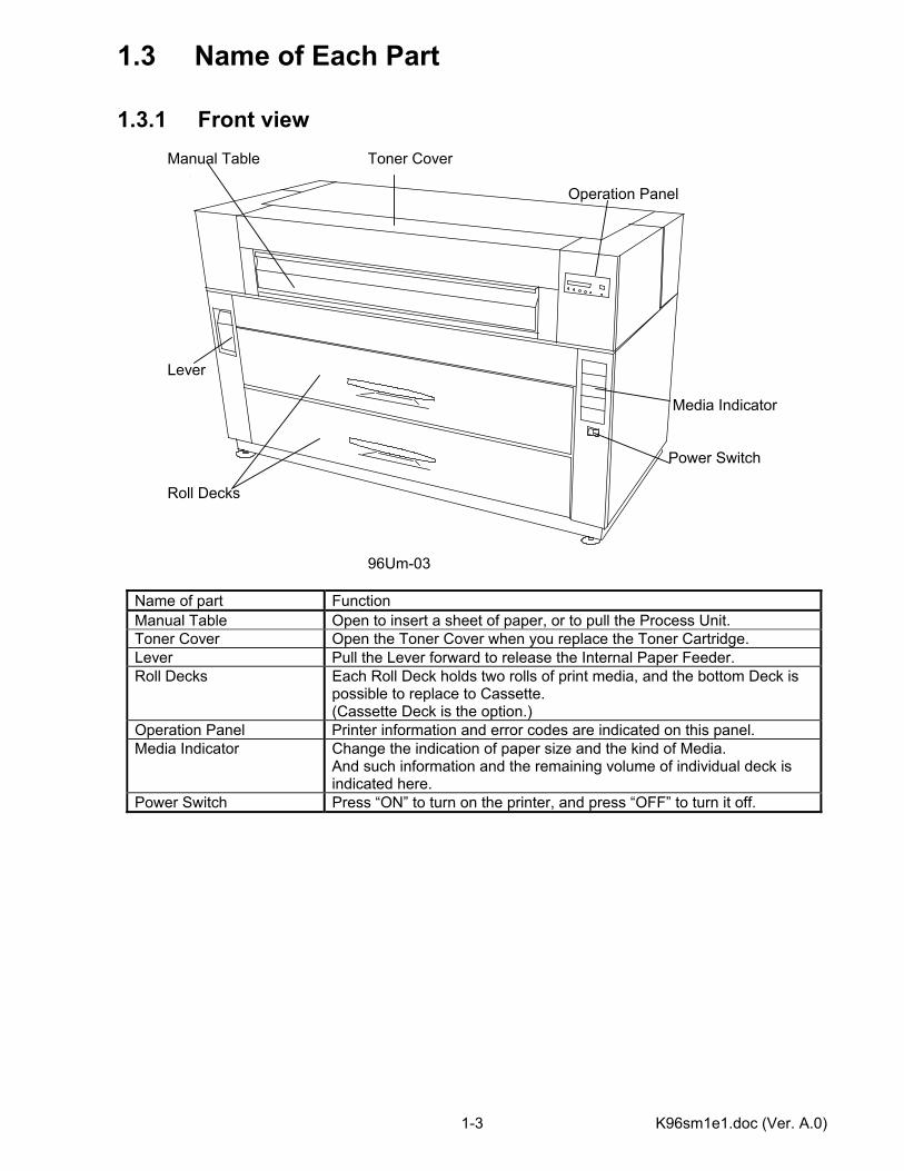
1.3 Name of Each Part 1.3.1 Front view Manual Table Toner Cover Operation Panel Lever Media Indicator Power Switch Roll Decks 96Um-03
Name of part Function Manual Table Open to insert a sheet of paper, or to pull the Process Unit. Toner Cover Open the Toner Cover when you replace the Toner Cartridge. Lever Pull the Lever forward to release the Internal Paper Feeder. Roll Decks Each Roll Deck holds two rolls of print media, and the bottom Deck is
possible to replace to Cassette. (Cassette Deck is the option.)
Operation Panel Printer information and error codes are indicated on this panel. Media Indicator Change the indication of paper size and the kind of Media.
And such information and the remaining volume of individual deck is indicated here.
Power Switch Press “ON” to turn on the printer, and press “OFF” to turn it off.
K96sm1e1.doc (Ver. A.0) 1-4
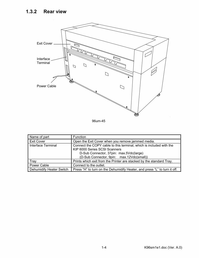
1.3.2 Rear view Exit Cover Interface Terminal Power Cable 96um-45
Name of part Function Exit Cover Open the Exit Cover when you remove jammed media. Interface Terminal Connect the COPY cable to this terminal, which is included with the
KIP 6000 Series SCSI Scanners D-Sub Connector, 37pin: max.5Vdc(large) (D-Sub Connector, 9pin: max.12Vdc(small))
Tray Prints which exit from the Printer are stacked by the standard Tray. Power Cable Connect to the outlet. Dehumidify Heater Switch Press “H” to turn on the Dehumidify Heater, and press “L” to turn it off.
K96sm2e1-1.doc (Ver. A.0)
Chapter 2
Installation Page 2.1 Required Conditions for the Installation Place 2- 1 2.2 Unpacking 2- 2 2.3 Removing Tape 2- 3 2.4 Attachment of Sub Plate 2- 4 2.5 The Contents of Accessories 2- 5 2.6 Setting up the Process Part 2- 6 2.6.1 Taking out the Process Unit from the machine 2- 6 2.6.2 Release the LED Head 2-10 2.6.3 Setting up the Process Unit 2-11 2.6.4 Installing the Process Unit to the machine 2-18 2.7 Installing the Print Tray 2-21
This machine is packaged and shipped after careful adjustment and passed a strict inspection in the factory. Installation is important work to reappear the efficiency of the machine that has passed the test in our factory after having installed at customer site. A service engineer has to understand this machine’s function very well, install this machine in a good environmental place in a correct procedure, and check this machine completely.
K96sm2e1-1.doc (Ver. A.0) 2-1
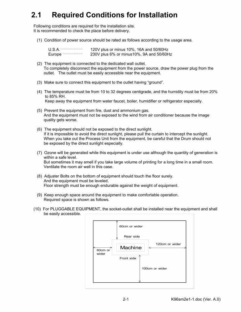
2.1 Required Conditions for Installation Following conditions are required for the installation site. It is recommended to check the place before delivery. (1) Condition of power source should be rated as follows according to the usage area. U.S.A. 120V plus or minus 10%, 16A and 50/60Hz Europe 230V plus 6% or minus10%, 9A and 50/60Hz (2) The equipment is connected to the dedicated wall outlet. To completely disconnect the equipment from the power source, draw the power plug from the outlet. The outlet must be easily accessible near the equipment. (3) Make sure to connect this equipment to the outlet having “ground”. (4) The temperature must be from 10 to 32 degrees centigrade, and the humidity must be from 20% to 85% RH. Keep away the equipment from water faucet, boiler, humidifier or refrigerator especially. (5) Prevent the equipment from fire, dust and ammonium gas. And the equipment must not be exposed to the wind from air conditioner because the image quality gets worse. (6) The equipment should not be exposed to the direct sunlight. If it is impossible to avoid the direct sunlight, please pull the curtain to intercept the sunlight. When you take out the Process Unit from the equipment, be careful that the Drum should not be exposed by the direct sunlight especially. (7) Ozone will be generated while this equipment is under use although the quantity of generation is within a safe level. But sometimes it may smell if you take large volume of printing for a long time in a small room. Ventilate the room air well in this case. (8) Adjuster Bolts on the bottom of equipment should touch the floor surely. And the equipment must be leveled. Floor strength must be enough endurable against the weight of equipment. (9) Keep enough space around the equipment to make comfortable operation. Required space is shown as follows. (10) For PLUGGABLE EQUIPMENT, the socket-outlet shall be installed near the equipment and shall
be easily accessible.
Machine
60cm or wider
Rear side
Front side
60cm orwider
120cm or wider
100cm or wider
K96sm2e1-1.doc (Ver. A.0) 2-2
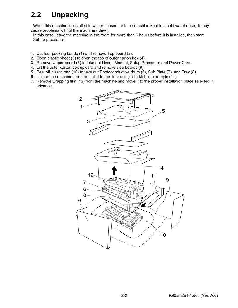
2.2 Unpacking When this machine is installed in winter season, or if the machine kept in a cold warehouse, it may cause problems with of the machine ( dew ). In this case, leave the machine in the room for more than 6 hours before it is installed, then start Set-up procedure. 1. Cut four packing bands (1) and remove Top board (2). 2. Open plastic sheet (3) to open the top of outer carton box (4). 3. Remove Upper board (5) to take out User’s Manual, Setup Procedure and Power Cord. 4. Lift the outer carton box upward and remove side boards (9). 5. Peel off plastic bag (10) to take out Photoconductive drum (6), Sub Plate (7), and Tray (8). 6. Unload the machine from the pallet to the floor using a forklift, for example (11). 7. Remove wrapping film (12) from the machine and move it to the proper installation place selected in advance.
12
3
4
5
67
8
10
9
91112
K96sm2e1-1.doc (Ver. A.0) 2-3
2.3 Removing Packing Tape
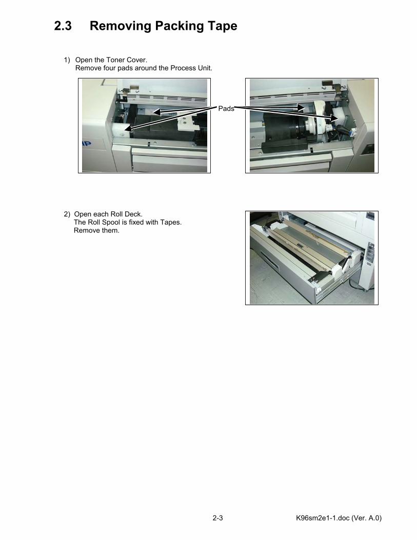
1) Open the Toner Cover. Remove four pads around the Process Unit.
Pads 2) Open each Roll Deck. The Roll Spool is fixed with Tapes. Remove them.

K96sm2e1-1.doc (Ver. A.0) 2-4
2.4 Attachment of Sub Plate 1. Insert Sub Plate A(2) between floor and Adjusters(1) located bottom of the machine.
For fitting direction, see illustration. 2. Loosen Adjusters to lower until it touches Sub Plate. 3. Slide Sub Plate in the arrow direction until it hits Positioning plate(3), respectively. 4. Fully lower all of four adjusters. 5. Fit four Brackets(4). (8 screws attached) 6. Lower four nuts(5) to fix these Brackets. 7. Fit short Covers (6). (4 screws attached) 8. Fit long Covers (8). (4 screws attached) 9. Fit two Brackets C(7). (4 screws attached)
1
2
1
4
M4x6
5
3
4
6
7
7
4 2
4
81
3
1
6
8

K96sm2e1-1.doc (Ver. A.0) 2-5
2.5 The Contents of Accessories Starprint 6000 Printer is attached with the following parts. 1. Photoconductive Drum 2. Sub Plate 3. Tray 4. Power Cord 5. Setup Procedure 6. User’s Manual
K96sm2e2(Ver.A.0) 2-6
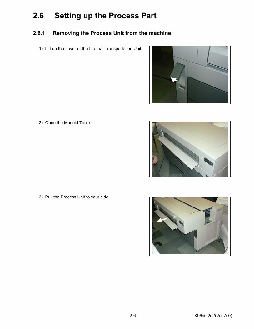
2.6 Setting up the Process Part 2.6.1 Removing the Process Unit from the machine 1) Lift up the Lever of the Internal Transportation Unit. 2) Open the Manual Table. 3) Pull the Process Unit to your side.
K96sm2e2(Ver.A.0) 2-7
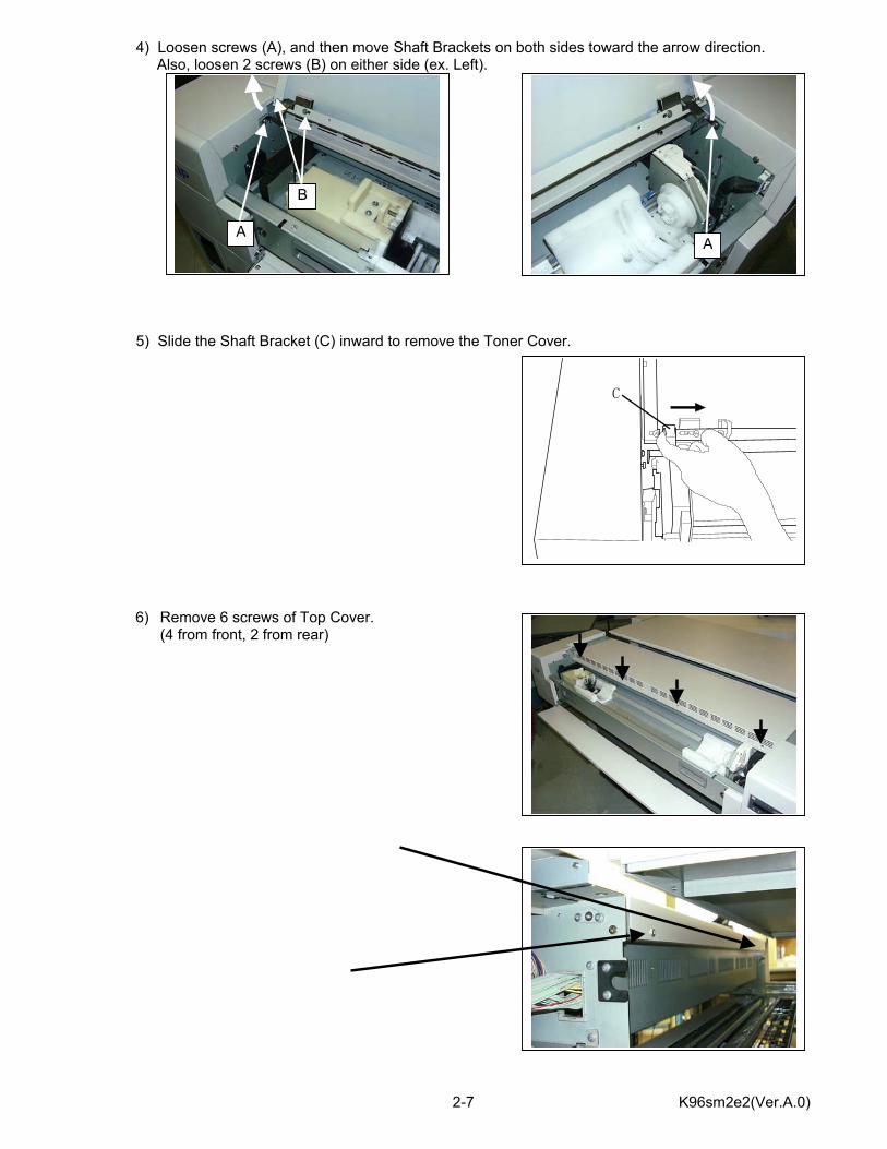
4) Loosen screws (A), and then move Shaft Brackets on both sides toward the arrow direction. Also, loosen 2 screws (B) on either side (ex. Left). 5) Slide the Shaft Bracket (C) inward to remove the Toner Cover.
6) Remove 6 screws of Top Cover. (4 from front, 2 from rear)
AA
B
C
K96sm2e2(Ver.A.0) 2-8
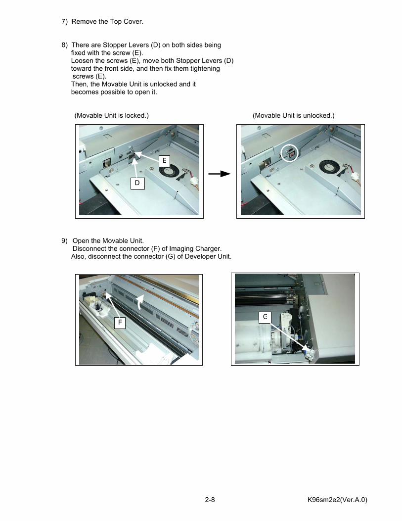
7) Remove the Top Cover. 8) There are Stopper Levers (D) on both sides being fixed with the screw (E). Loosen the screws (E), move both Stopper Levers (D)
toward the front side, and then fix them tightening screws (E).
Then, the Movable Unit is unlocked and it becomes possible to open it. (Movable Unit is locked.) (Movable Unit is unlocked.)
9) Open the Movable Unit. Disconnect the connector (F) of Imaging Charger.
Also, disconnect the connector (G) of Developer Unit.
D
E
FG
K96sm2e2(Ver.A.0) 2-9
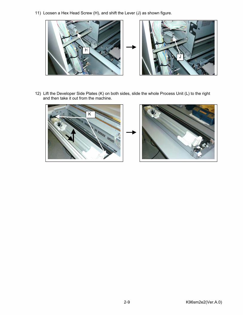
11) Loosen a Hex Head Screw (H), and shift the Lever (J) as shown figure. 12) Lift the Developer Side Plates (K) on both sides, slide the whole Process Unit (L) to the right and then take it out from the machine.
HJ
K
K96sm2e2(Ver.A.0) 2-10
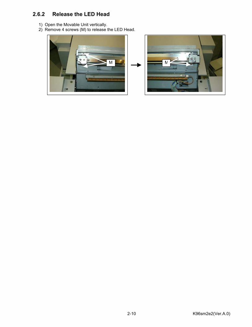
2.6.2 Release the LED Head 1) Open the Movable Unit vertically. 2) Remove 4 screws (M) to release the LED Head.
MM
K96sm2e3.doc3 (Ver. A.0) 2-11
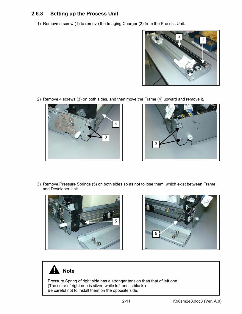
2.6.3 Setting up the Process Unit 1) Remove a screw (1) to remove the Imaging Charger (2) from the Process Unit. 2) Remove 4 screws (3) on both sides, and then move the Frame (4) upward and remove it. 3) Remove Pressure Springs (5) on both sides so as not to lose them, which exist between Frame and Developer Unit.
Note Pressure Spring of right side has a stronger tension than that of left one. (The color of right one is silver, while left one is black.) Be careful not to install them on the opposite side.
12
3
4
3
5
5
K96sm2e3.doc3 (Ver. A.0) 2-12
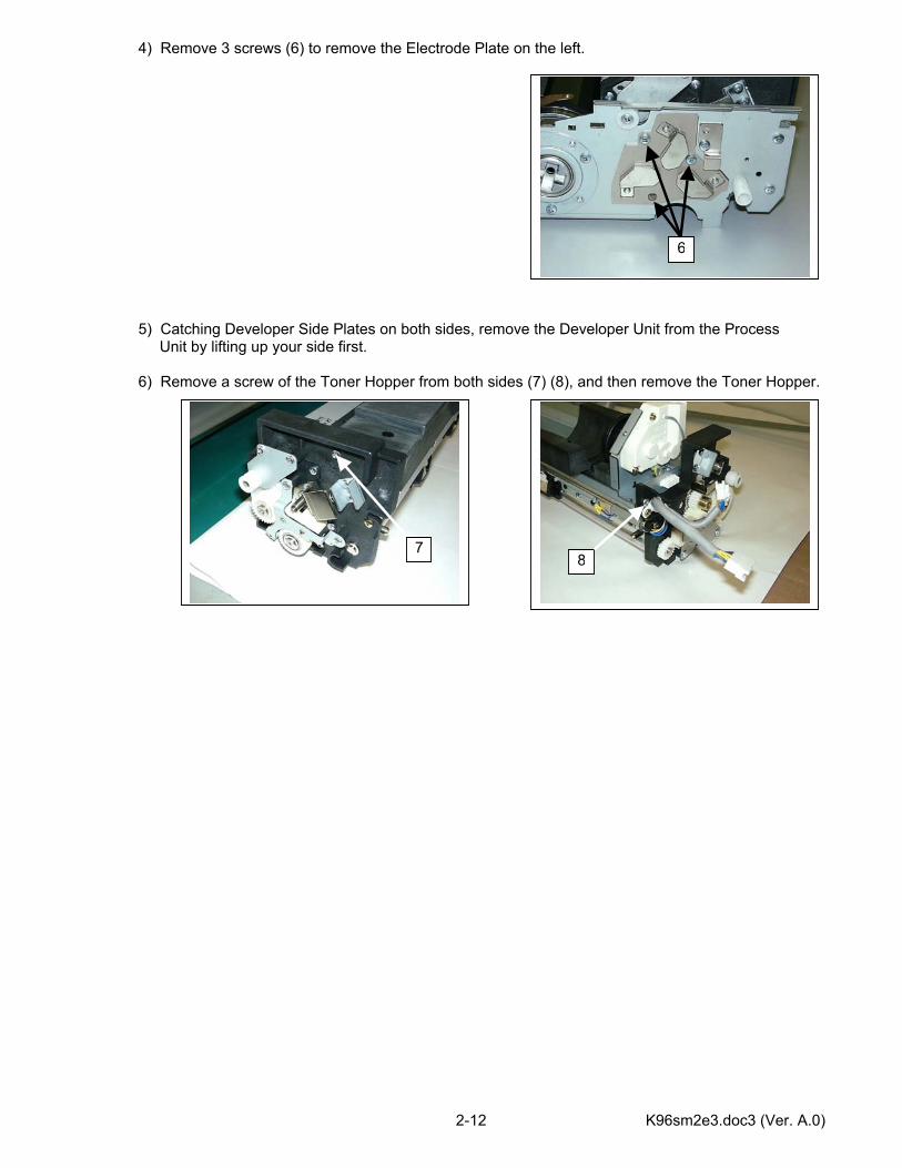
4) Remove 3 screws (6) to remove the Electrode Plate on the left. 5) Catching Developer Side Plates on both sides, remove the Developer Unit from the Process Unit by lifting up your side first. 6) Remove a screw of the Toner Hopper from both sides (7) (8), and then remove the Toner Hopper.
6
78
K96sm2e3.doc3 (Ver. A.0) 2-13
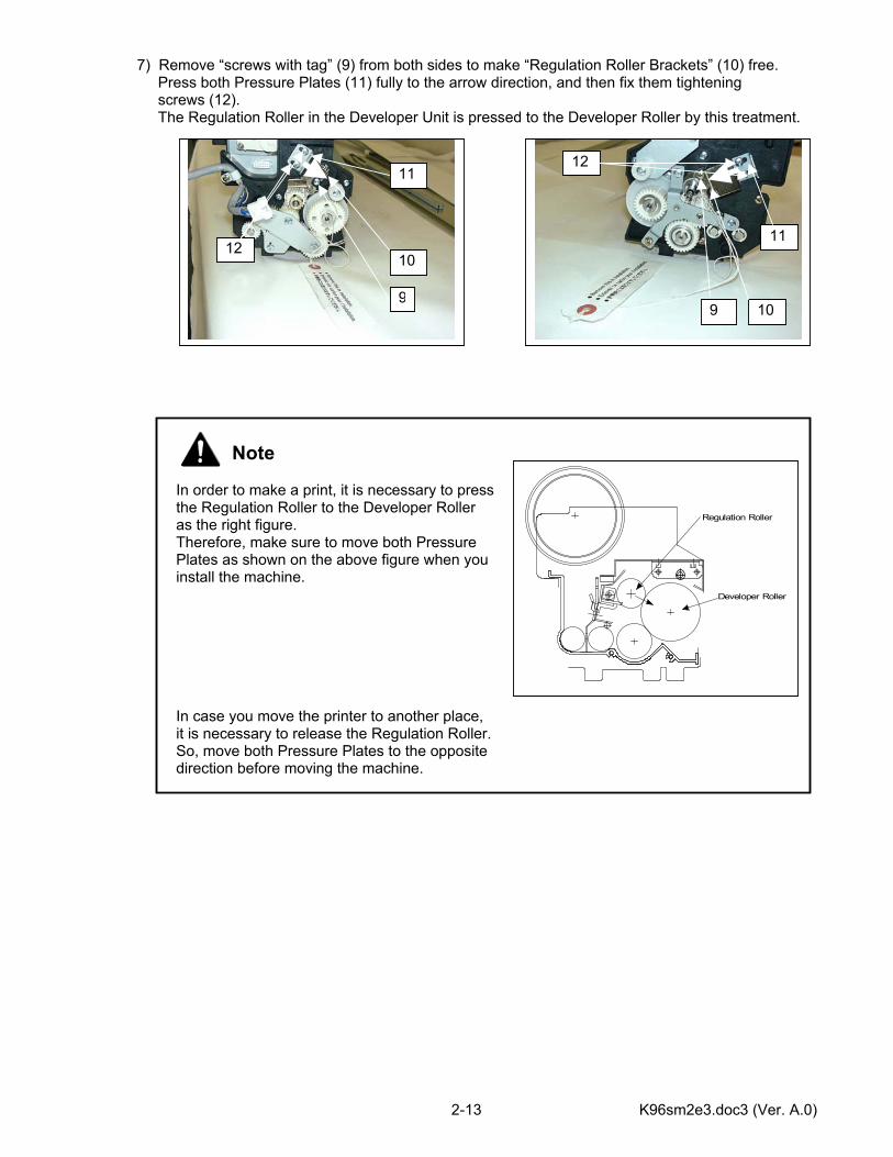
7) Remove “screws with tag” (9) from both sides to make “Regulation Roller Brackets” (10) free. Press both Pressure Plates (11) fully to the arrow direction, and then fix them tightening screws (12). The Regulation Roller in the Developer Unit is pressed to the Developer Roller by this treatment.
Note In order to make a print, it is necessary to press the Regulation Roller to the Developer Roller as the right figure. Therefore, make sure to move both Pressure Plates as shown on the above figure when you install the machine. In case you move the printer to another place, it is necessary to release the Regulation Roller. So, move both Pressure Plates to the opposite direction before moving the machine.
Regulation Roller
Developer Roller
99
10
10
11
1112
12
K96sm2e3.doc3 (Ver. A.0) 2-14
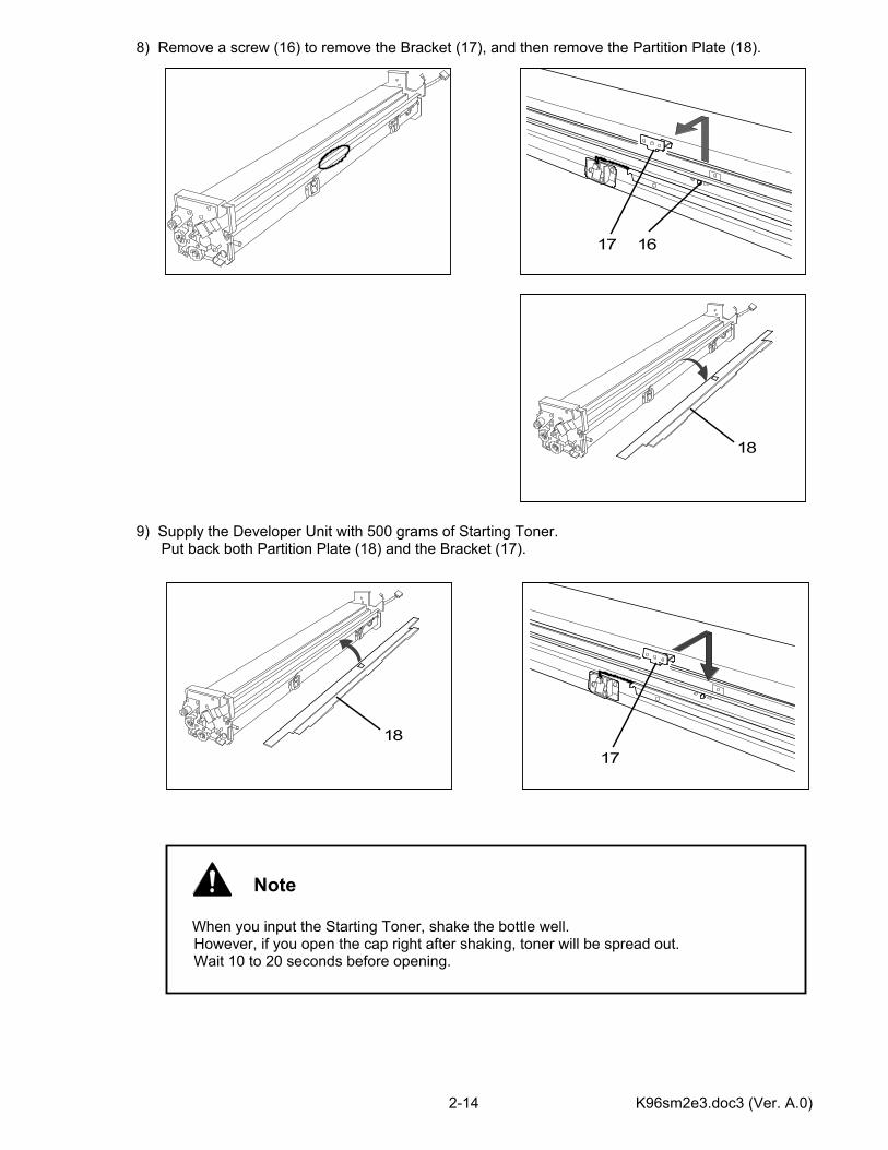
8) Remove a screw (16) to remove the Bracket (17), and then remove the Partition Plate (18). 9) Supply the Developer Unit with 500 grams of Starting Toner. Put back both Partition Plate (18) and the Bracket (17).
1617
18
17
18
Note
When you input the Starting Toner, shake the bottle well.
However, if you open the cap right after shaking, toner will be spread out. Wait 10 to 20 seconds before opening.
K96sm2e3.doc3 (Ver. A.0) 2-15
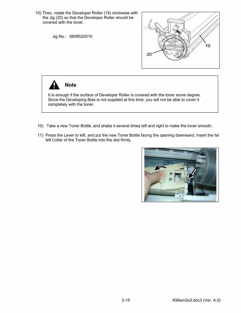
10) Then, rotate the Developer Roller (19) clockwise with the Jig (20) so that the Developer Roller should be covered with the toner.
Jig No.: 6608520010
10) Take a new Toner Bottle, and shake it several times left and right to make the toner smooth. 11) Press the Lever to left, and put the new Toner Bottle facing the opening downward. Insert the far
left Collar of the Toner Bottle Into the slot firmly.
20
19
Note It is enough if the surface of Developer Roller is covered with the toner some degree. Since the Developing Bias is not supplied at this time, you will not be able to cover it completely with the toner.
K96sm2e3.doc3 (Ver. A.0) 2-16
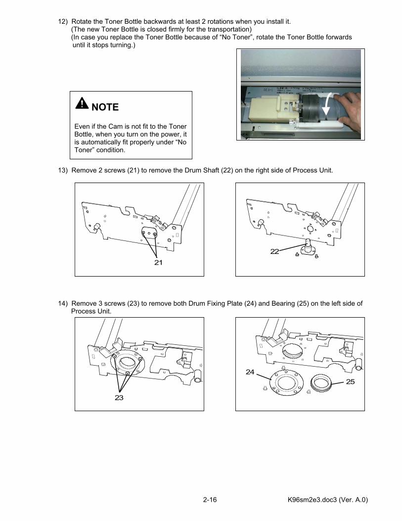
12) Rotate the Toner Bottle backwards at least 2 rotations when you install it. (The new Toner Bottle is closed firmly for the transportation) (In case you replace the Toner Bottle because of “No Toner”, rotate the Toner Bottle forwards
until it stops turning.) 13) Remove 2 screws (21) to remove the Drum Shaft (22) on the right side of Process Unit. 14) Remove 3 screws (23) to remove both Drum Fixing Plate (24) and Bearing (25) on the left side of Process Unit.
21
22
23
2425
NOTE Even if the Cam is not fit to the Toner Bottle, when you turn on the power, it is automatically fit properly under “No Toner” condition.
K96sm2e3.doc3 (Ver. A.0) 2-17
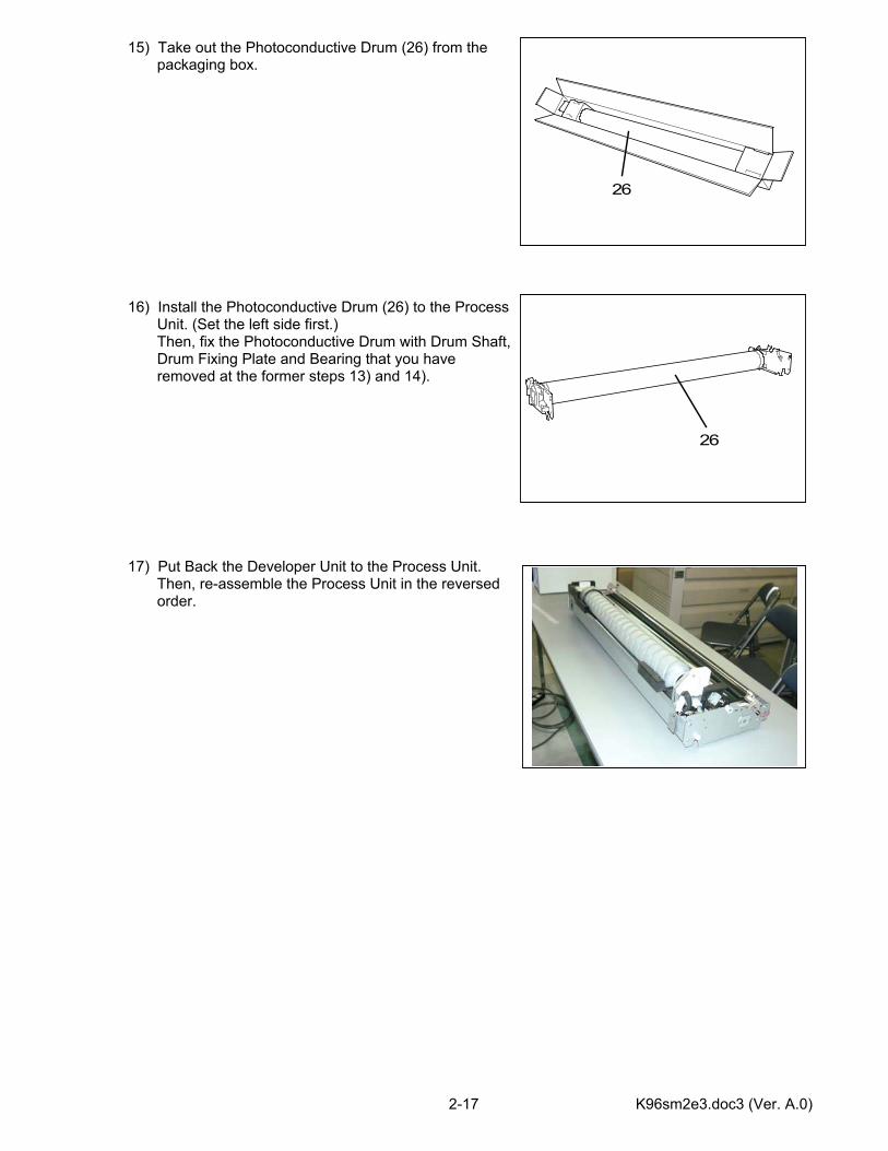
15) Take out the Photoconductive Drum (26) from the packaging box. 16) Install the Photoconductive Drum (26) to the Process Unit. (Set the left side first.) Then, fix the Photoconductive Drum with Drum Shaft, Drum Fixing Plate and Bearing that you have removed at the former steps 13) and 14). 17) Put Back the Developer Unit to the Process Unit. Then, re-assemble the Process Unit in the reversed order.
26
26
K96sm2e4.doc (Ver. A.0) 2-18
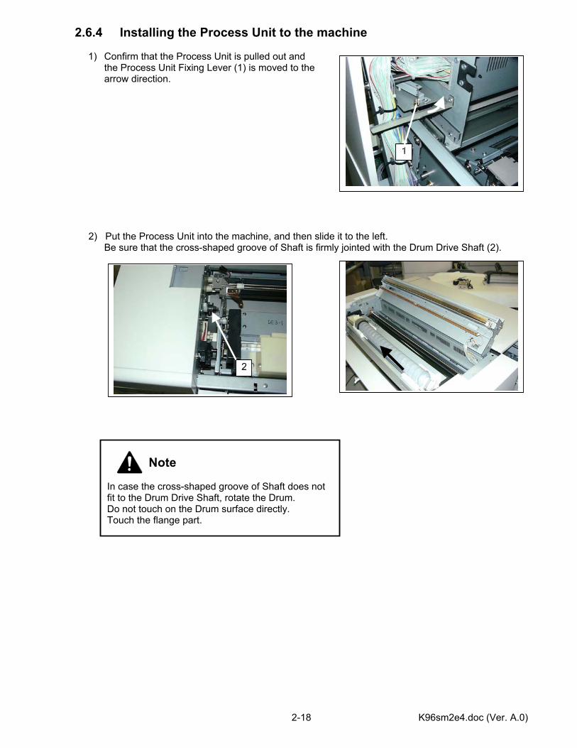
Note In case the cross-shaped groove of Shaft does not fit to the Drum Drive Shaft, rotate the Drum. Do not touch on the Drum surface directly. Touch the flange part.
2.6.4 Installing the Process Unit to the machine
1) Confirm that the Process Unit is pulled out and the Process Unit Fixing Lever (1) is moved to the arrow direction.
2) Put the Process Unit into the machine, and then slide it to the left.
Be sure that the cross-shaped groove of Shaft is firmly jointed with the Drum Drive Shaft (2).
1
2
K96sm2e4.doc (Ver. A.0) 2-19
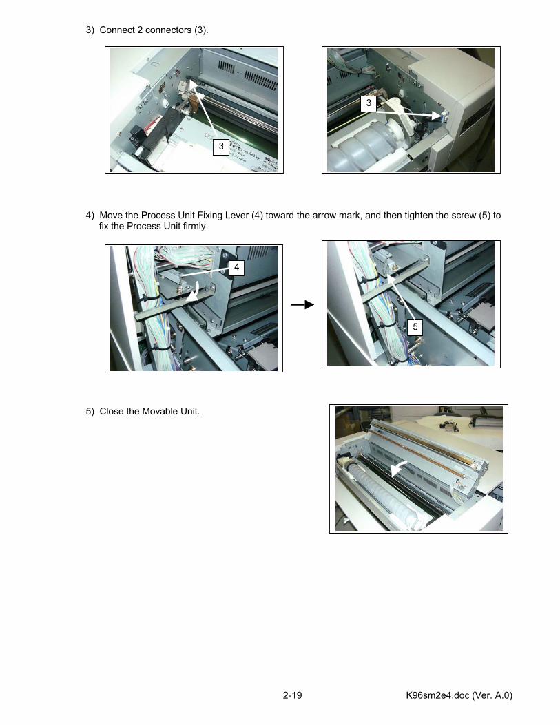
3) Connect 2 connectors (3). 4) Move the Process Unit Fixing Lever (4) toward the arrow mark, and then tighten the screw (5) to fix the Process Unit firmly. 5) Close the Movable Unit.
3
3
4
5
K96sm2e4.doc (Ver. A.0) 2-20
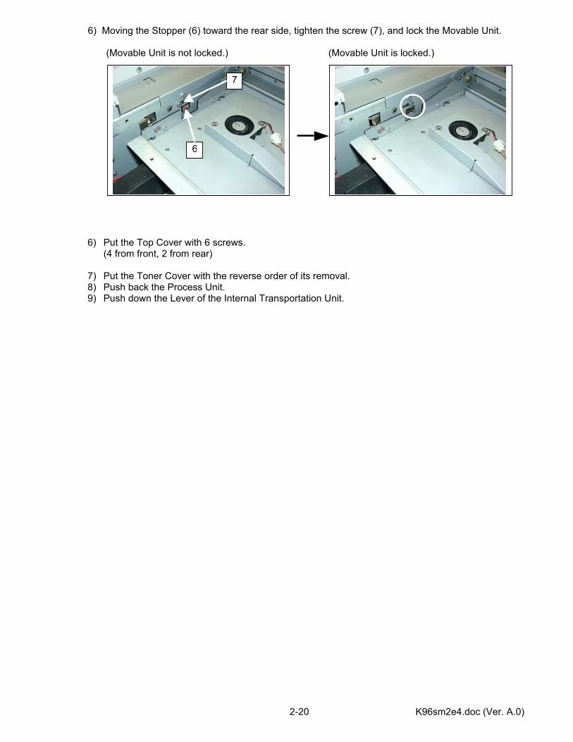
6) Moving the Stopper (6) toward the rear side, tighten the screw (7), and lock the Movable Unit. (Movable Unit is not locked.) (Movable Unit is locked.)
6) Put the Top Cover with 6 screws. (4 from front, 2 from rear)
7) Put the Toner Cover with the reverse order of its removal. 8) Push back the Process Unit. 9) Push down the Lever of the Internal Transportation Unit.
6
7
K96sm2e4.doc (Ver. A.0) 2-21
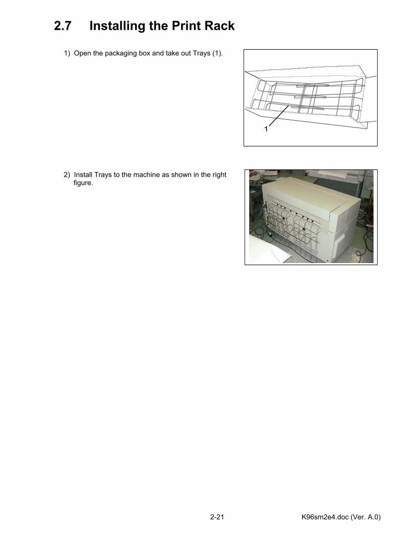
2.7 Installing the Print Rack 1) Open the packaging box and take out Trays (1). 2) Install Trays to the machine as shown in the right figure.
1
K96sm3e1.doc (Ver. A.0)
Chapter 3
Print Process Page 3.1 Characteristic of Toner 3- 1 3.2 Print Processes 3- 2 3.2.1 Erasing (Removal of negative electric charges) 3- 4 3.2.2 Charge of Drum 3- 5 3.2.3 Exposure 3- 6 3.2.4 Development 3- 7 3.2.5 Pre-transfer LED 3- 9 3.2.6 Transfer 3-11 3.2.7 Separation 3-12 3.2.8 Drum Cleaning (Removal of remained toner) 3-13 3.2.9 Fusing 3-14 3.3 Controlling the Movement of Toner in the Developer Unit 3-15 3.4 Toner Collection Process 3-18
K96sm3e1.doc (Ver. A.0) 3-1
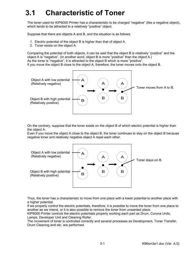
3.1 Characteristic of Toner The toner used for KIP6000 Printer has a characteristic to be charged “negative” (like a negative object), which tends to be attracted to a relatively “positive” object. Suppose that there are objects A and B, and the situation is as follows. 1. Electric potential of the object B is higher than that of object A. 2. Toner exists on the object A. Comparing the potential of both objects, it can be said that the object B is relatively “positive” and the object A is “negative”. (In another word, object B is more “positive” than the object A.) As the toner is “negative”, it is attracted to the object B which is more “positive”. If you move the object B close to the object A, therefore, the toner moves onto the object B. Object A with low potential (Relatively negative) Toner moves from A to B. Object B with high potential (Relatively positive) On the contrary, suppose that the toner exists on the object B of which electric potential is higher than the object A. Even if you move the object A close to the object B, the toner continues to stay on the object B because negative toner and relatively negative object A repel each other. Object A with low potential (Relatively negative) Toner stays on B. Object B with high potential (Relatively positive) Thus, the toner has a characteristic to move from one place with a lower potential to another place with a higher potential. If we properly control the electric potentials, therefore, it is possible to move the toner from one place to another as we intend, or it is also possible to remove the toner from unwanted place. KIP6000 Printer controls the electric potentials properly working each part as Drum, Corona Units, Lamps, Developer Unit and Cleaning Roller. The movement of toner is controlled correctly and several processes as Development, Toner Transfer, Drum Cleaning and etc. are performed.
A
B
A
B
A
B
A
B
A
B
A
B
K96sm3e1.doc (Ver. A.0) 3-2
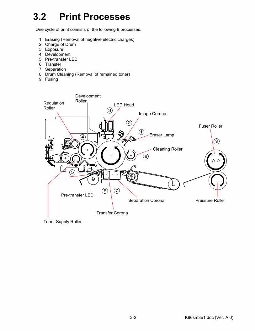
3.2 Print Processes One cycle of print consists of the following 9 processes. 1. Erasing (Removal of negative electric charges) 2. Charge of Drum 3. Exposure 4. Development 5. Pre-transfer LED 6. Transfer 7. Separation 8. Drum Cleaning (Removal of remained toner) 9. Fusing
41
2
3
5
6 7
8
9
Image Corona
LED Head
Cleaning Roller
Eraser Lamp
Regulation Roller
Toner Supply Roller
Development Roller
Pre-transfer LED
Transfer Corona
Separation Corona Pressure Roller
Fuser Roller
K96sm3e1.doc (Ver. A.0) 3-3
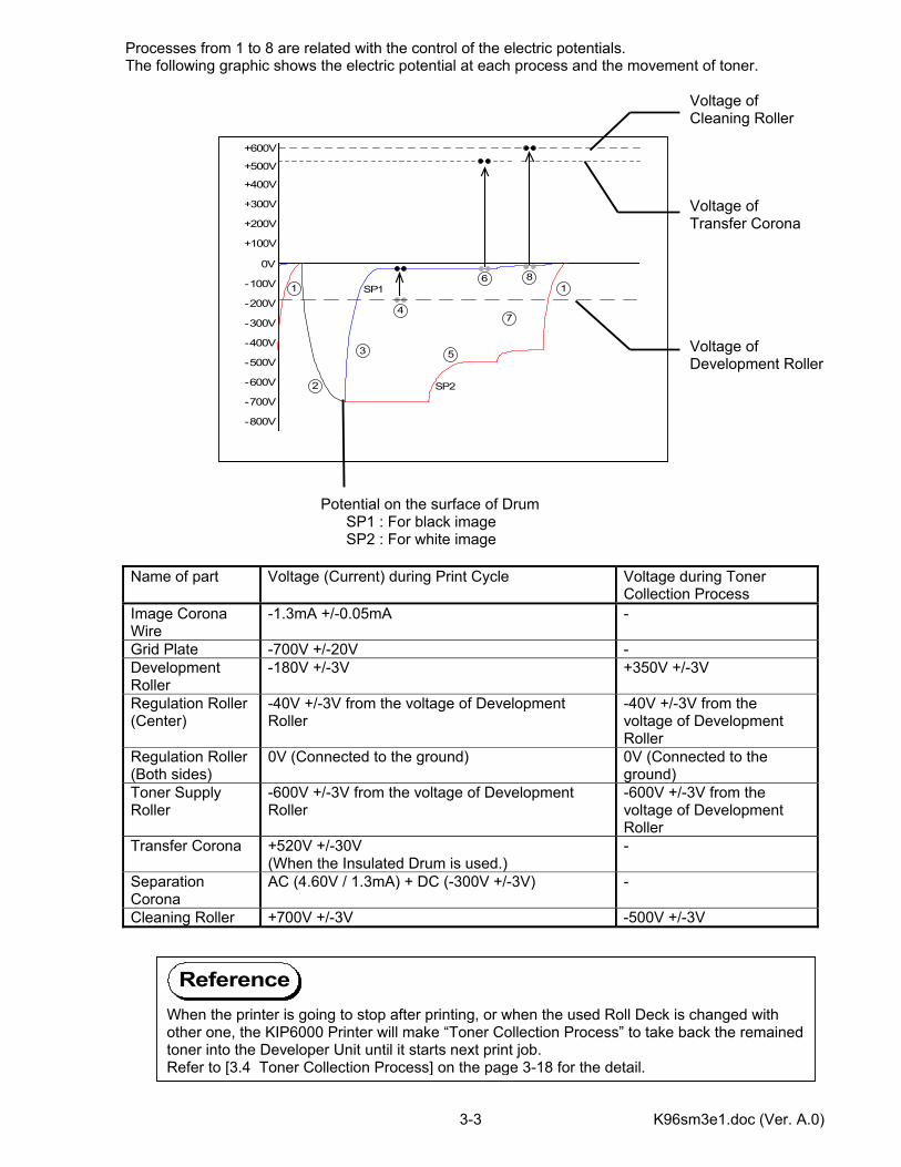
Processes from 1 to 8 are related with the control of the electric potentials. The following graphic shows the electric potential at each process and the movement of toner. Voltage of Cleaning Roller Voltage of Transfer Corona Voltage of Development Roller Potential on the surface of Drum SP1 : For black image SP2 : For white image
Name of part Voltage (Current) during Print Cycle Voltage during Toner Collection Process
Image Corona Wire
-1.3mA +/-0.05mA -
Grid Plate -700V +/-20V - Development Roller
-180V +/-3V +350V +/-3V
Regulation Roller (Center)
-40V +/-3V from the voltage of Development Roller
-40V +/-3V from the voltage of Development Roller
Regulation Roller (Both sides)
0V (Connected to the ground) 0V (Connected to the ground)
Toner Supply Roller
-600V +/-3V from the voltage of Development Roller
-600V +/-3V from the voltage of Development Roller
Transfer Corona +520V +/-30V (When the Insulated Drum is used.)
-
Separation Corona
AC (4.60V / 1.3mA) + DC (-300V +/-3V) -
Cleaning Roller +700V +/-3V -500V +/-3V
0V
-100V
-200V
-300V
-400V
-500V
-600V
-700V
-800V
+400V
+300V
+200V
+100V
+500V
8
2
3
4
5
6
7
1
+600V
SP1
SP2
1
When the printer is going to stop after printing, or when the used Roll Deck is changed with other one, the KIP6000 Printer will make “Toner Collection Process” to take back the remainedtoner into the Developer Unit until it starts next print job. Refer to [3.4 Toner Collection Process] on the page 3-18 for the detail.
Reference
K96sm3e1.doc (Ver. A.0) 3-4
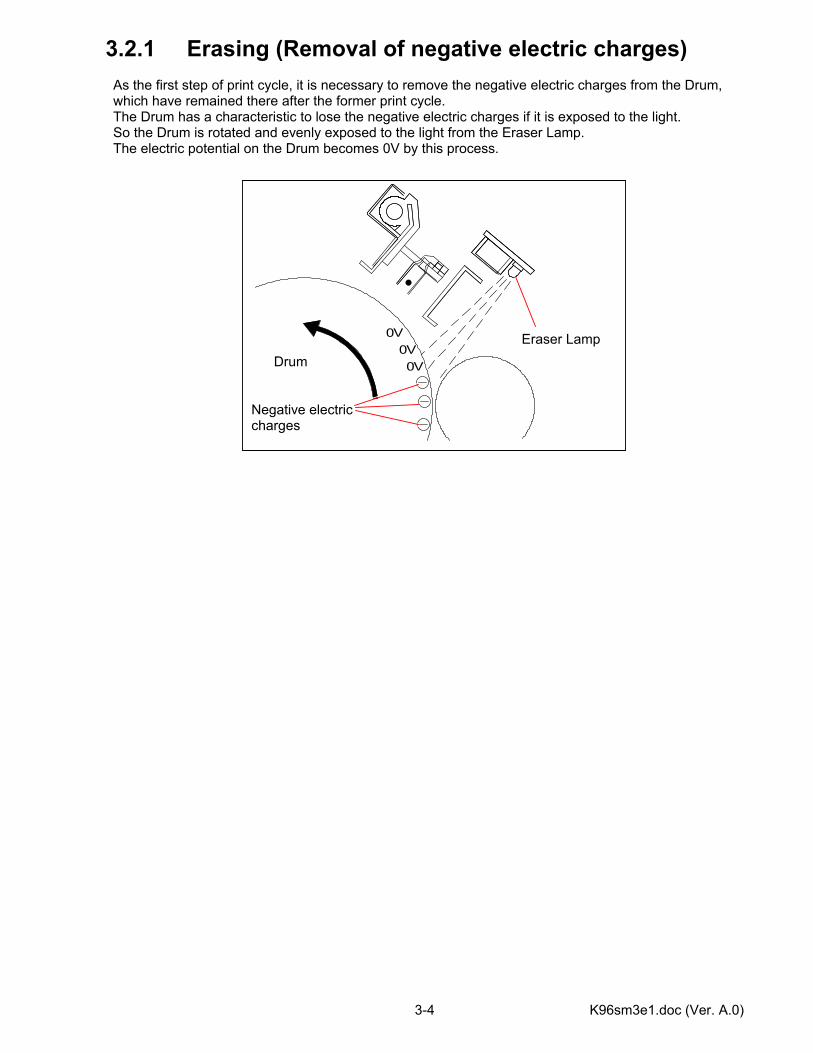
3.2.1 Erasing (Removal of negative electric charges) As the first step of print cycle, it is necessary to remove the negative electric charges from the Drum, which have remained there after the former print cycle. The Drum has a characteristic to lose the negative electric charges if it is exposed to the light. So the Drum is rotated and evenly exposed to the light from the Eraser Lamp. The electric potential on the Drum becomes 0V by this process.
0V
0V0V
Eraser Lamp Drum
Negative electric charges
K96sm3e1.doc (Ver. A.0) 3-5
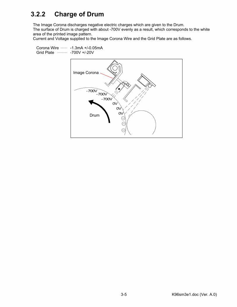
3.2.2 Charge of Drum The Image Corona discharges negative electric charges which are given to the Drum. The surface of Drum is charged with about -700V evenly as a result, which corresponds to the white area of the printed image pattern. Current and Voltage supplied to the Image Corona Wire and the Grid Plate are as follows. Corona Wire -1.3mA +/-0.05mA Grid Plate -700V +/-20V
0V
0V0V
-700V-700V
-700V
Image Corona
Drum
K96sm3e1.doc (Ver. A.0) 3-6
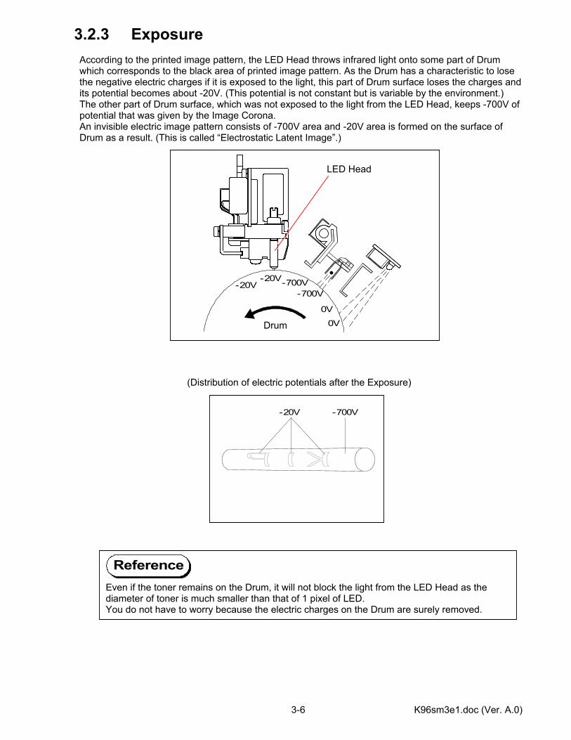
3.2.3 Exposure According to the printed image pattern, the LED Head throws infrared light onto some part of Drum which corresponds to the black area of printed image pattern. As the Drum has a characteristic to lose the negative electric charges if it is exposed to the light, this part of Drum surface loses the charges and its potential becomes about -20V. (This potential is not constant but is variable by the environment.) The other part of Drum surface, which was not exposed to the light from the LED Head, keeps -700V of potential that was given by the Image Corona. An invisible electric image pattern consists of -700V area and -20V area is formed on the surface of Drum as a result. (This is called “Electrostatic Latent Image”.) (Distribution of electric potentials after the Exposure)
-700V-700V-20V
0V0V
-20V
-20V -700V
LED Head
Drum
Even if the toner remains on the Drum, it will not block the light from the LED Head as the diameter of toner is much smaller than that of 1 pixel of LED. You do not have to worry because the electric charges on the Drum are surely removed.
Reference
K96sm3e1.doc (Ver. A.0) 3-7
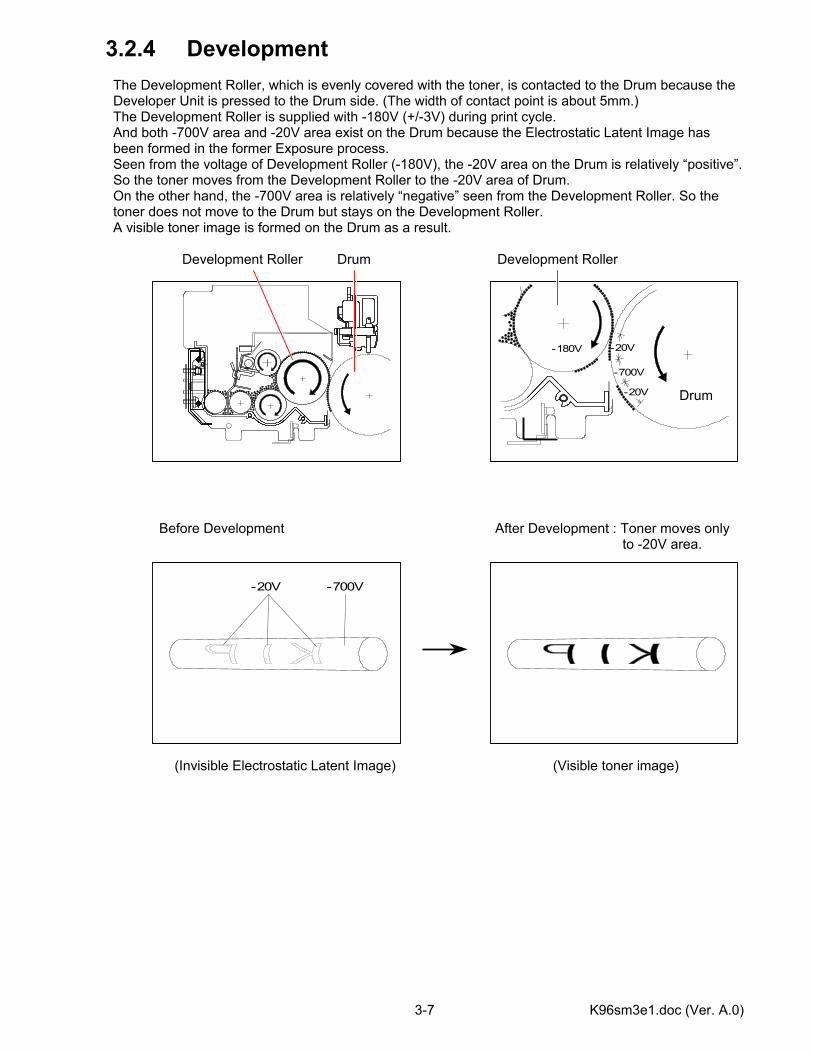
3.2.4 Development The Development Roller, which is evenly covered with the toner, is contacted to the Drum because the Developer Unit is pressed to the Drum side. (The width of contact point is about 5mm.) The Development Roller is supplied with -180V (+/-3V) during print cycle. And both -700V area and -20V area exist on the Drum because the Electrostatic Latent Image has been formed in the former Exposure process. Seen from the voltage of Development Roller (-180V), the -20V area on the Drum is relatively “positive”. So the toner moves from the Development Roller to the -20V area of Drum. On the other hand, the -700V area is relatively “negative” seen from the Development Roller. So the toner does not move to the Drum but stays on the Development Roller. A visible toner image is formed on the Drum as a result. Development Roller Drum Development Roller Before Development After Development : Toner moves only to -20V area. (Invisible Electrostatic Latent Image) (Visible toner image)
-700V
-20V
-20V
-180V
Drum
-20V -700V
K96sm3e1.doc (Ver. A.0) 3-8
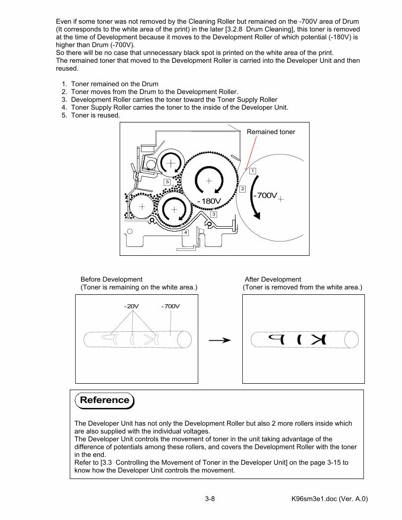
Even if some toner was not removed by the Cleaning Roller but remained on the -700V area of Drum (It corresponds to the white area of the print) in the later [3.2.8 Drum Cleaning], this toner is removed at the time of Development because it moves to the Development Roller of which potential (-180V) is higher than Drum (-700V). So there will be no case that unnecessary black spot is printed on the white area of the print. The remained toner that moved to the Development Roller is carried into the Developer Unit and then reused. 1. Toner remained on the Drum 2. Toner moves from the Drum to the Development Roller. 3. Development Roller carries the toner toward the Toner Supply Roller 4. Toner Supply Roller carries the toner to the inside of the Developer Unit. 5. Toner is reused. Before Development After Development (Toner is remaining on the white area.) (Toner is removed from the white area.)
1
2
3
4
5
-700V-180V
The Developer Unit has not only the Development Roller but also 2 more rollers inside which are also supplied with the individual voltages. The Developer Unit controls the movement of toner in the unit taking advantage of the difference of potentials among these rollers, and covers the Development Roller with the toner in the end. Refer to [3.3 Controlling the Movement of Toner in the Developer Unit] on the page 3-15 to know how the Developer Unit controls the movement.
Remained toner
Reference
-20V -700V
K96sm3e1.doc (Ver. A.0) 3-9
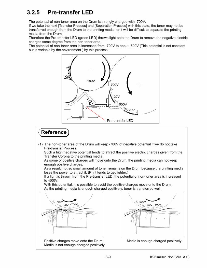
3.2.5 Pre-transfer LED The potential of non-toner area on the Drum is strongly charged with -700V. If we take the next [Transfer Process] and [Separation Process] with this state, the toner may not be transferred enough from the Drum to the printing media, or it will be difficult to separate the printing media from the Drum. Therefore the Pre-transfer LED (green LED) throws light onto the Drum to remove the negative electric charges some degree from the non-toner area. The potential of non-toner area is increased from -700V to about -500V (This potential is not constant but is variable by the environment.) by this process.
(1) The non-toner area of the Drum will keep -700V of negative potential if we do not take Pre-transfer Process. Such a high negative potential tends to attract the positive electric charges given from the Transfer Corona to the printing media. As some of positive charges will move onto the Drum, the printing media can not keep enough positive charges. As a result, not so small amount of toner remains on the Drum because the printing media loses the power to attract it. (Print tends to get lighter.) If a light is thrown from the Pre-transfer LED, the potential of non-toner area is increased to -500V. With this potential, it is possible to avoid the positive charges move onto the Drum. As the printing media is enough charged positively, toner is transferred well. Positive charges move onto the Drum. Media is enough charged positively. Media is not enough charged positively.
-20V
-700V
-500V
-20V
-180V
-20V -700V-700V
Pre-transfer LED
Reference
-20V -500V-500V

K96sm3e1.doc (Ver. A.0) 3-10
(2) -700V of potential on the non-toner area is so strong that the media, which is charged positively by the Transfer Process, is strongly attracted to this -700V area by the static force. So it is difficult to separate the media from the Drum, which will result in a jam or other problems. If the Pre-transfer LED throws light to the non-toner area, the negative charges are removed from the non-toner area and the static force gets weaker. It becomes easier to separate the media from the Drum as a result.
Reference
K96sm3e1.doc (Ver. A.0) 3-11
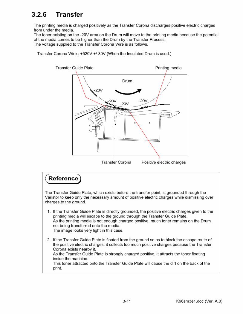
3.2.6 Transfer The printing media is charged positively as the Transfer Corona discharges positive electric charges from under the media. The toner existing on the -20V area on the Drum will move to the printing media because the potential of the media comes to be higher than the Drum by the Transfer Process. The voltage supplied to the Transfer Corona Wire is as follows. Transfer Corona Wire : +520V +/-30V (When the Insulated Drum is used.) Transfer Guide Plate Printing media Transfer Corona Positive electric charges
-20V-20V
-20V
-20V
Drum
The Transfer Guide Plate, which exists before the transfer point, is grounded through the Varistor to keep only the necessary amount of positive electric charges while dismissing over charges to the ground. 1. If the Transfer Guide Plate is directly grounded, the positive electric charges given to the printing media will escape to the ground through the Transfer Guide Plate. As the printing media is not enough charged positive, much toner remains on the Drum not being transferred onto the media. The image looks very light in this case. 2. If the Transfer Guide Plate is floated from the ground so as to block the escape route of the positive electric charges, it collects too much positive charges because the Transfer Corona exists nearby it. As the Transfer Guide Plate is strongly charged positive, it attracts the toner floating inside the machine. This toner attracted onto the Transfer Guide Plate will cause the dirt on the back of the print.
Reference
K96sm3e1.doc (Ver. A.0) 3-12
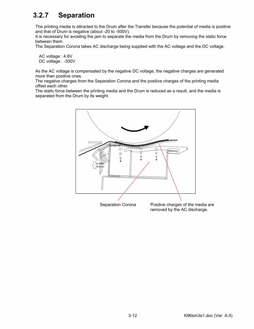
3.2.7 Separation The printing media is attracted to the Drum after the Transfer because the potential of media is positive and that of Drum is negative (about -20 to -500V). It is necessary for avoiding the jam to separate the media from the Drum by removing the static force between them. The Separation Corona takes AC discharge being supplied with the AC voltage and the DC voltage. AC voltage : 4.6V DC voltage : -300V As the AC voltage is compensated by the negative DC voltage, the negative charges are generated more than positive ones. The negative charges from the Separation Corona and the positive charges of the printing media offset each other. The static force between the printing media and the Drum is reduced as a result, and the media is separated from the Drum by its weight. Separation Corona Positive charges of the media are removed by the AC discharge.
K96sm3e1.doc (Ver. A.0) 3-13
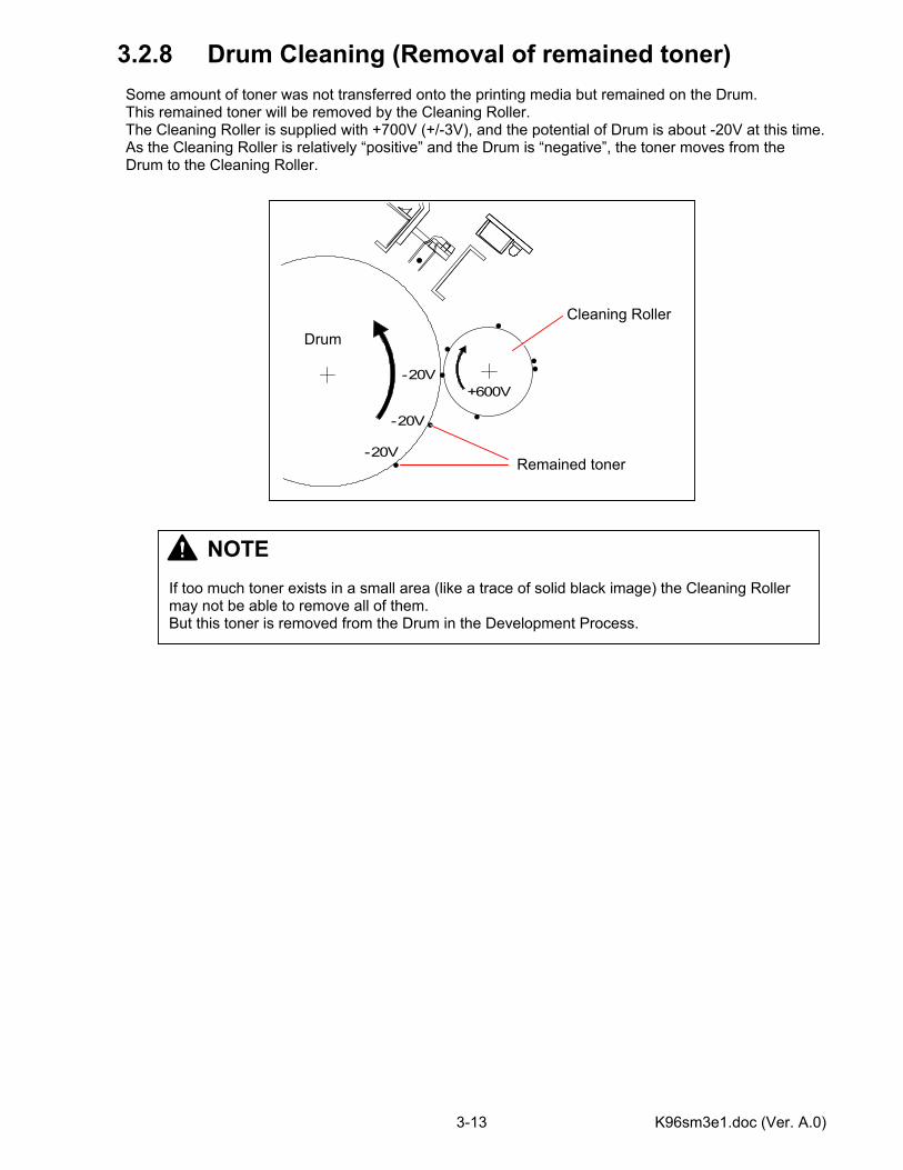
3.2.8 Drum Cleaning (Removal of remained toner) Some amount of toner was not transferred onto the printing media but remained on the Drum. This remained toner will be removed by the Cleaning Roller. The Cleaning Roller is supplied with +700V (+/-3V), and the potential of Drum is about -20V at this time. As the Cleaning Roller is relatively “positive” and the Drum is “negative”, the toner moves from the Drum to the Cleaning Roller.
-20V
-20V
-20V
+600V
Cleaning Roller Drum
Remained toner
NOTE If too much toner exists in a small area (like a trace of solid black image) the Cleaning Roller may not be able to remove all of them. But this toner is removed from the Drum in the Development Process.
K96sm3e1.doc (Ver. A.0) 3-14
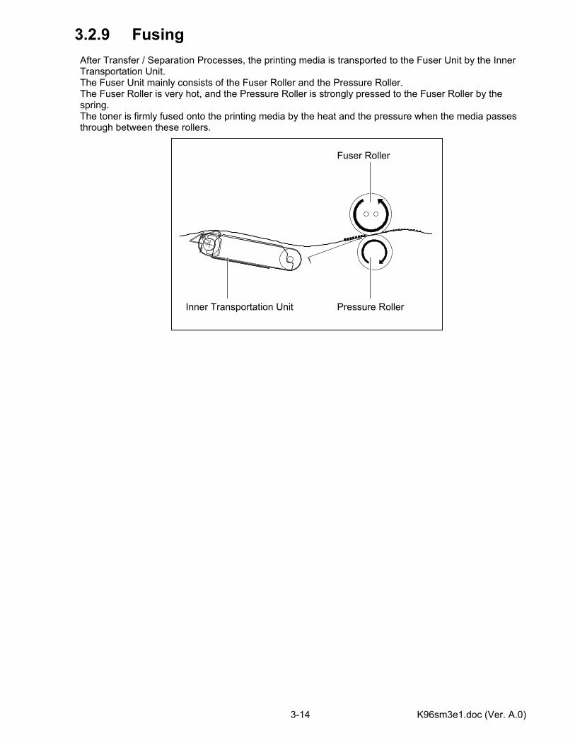
3.2.9 Fusing After Transfer / Separation Processes, the printing media is transported to the Fuser Unit by the Inner Transportation Unit. The Fuser Unit mainly consists of the Fuser Roller and the Pressure Roller. The Fuser Roller is very hot, and the Pressure Roller is strongly pressed to the Fuser Roller by the spring. The toner is firmly fused onto the printing media by the heat and the pressure when the media passes through between these rollers.
Pressure Roller
Fuser Roller
Inner Transportation Unit

K96sm3e1.doc (Ver. A.0) 3-15
3.3 Controlling the Movement of Toner in the Developer Unit There are 3 kinds of rollers called “Development Roller”, “Regulation Roller” and “Toner Supply Roller” in the Developer Unit. Each roller is supplied with its own voltage. In the following list, the voltage of the Development Roller (-180V) is measured against the ground. The other voltages mean the difference against the voltage of Development Roller.
Name of roller Supplied voltage Development Roller -180V +/-3V against the ground Regulation Roller (Center) -40V against the voltage of Development Roller Regulation Roller (Both sides) 0V (Connected to the ground) Toner Supply Roller -600V against the voltage of Development Roller
Regulation Roller : Both sides Insulator Regulation Roller : Center (0V : Connected to GND) (-40V against Development Roller voltage) Development Roller (-180V against GND) Toner Supply Roller (-600V against Development Roller voltage)
NOTE The Regulation Roller is divided into central area and both sides area by the insulator, and individual voltages is supplied to each area.
K96sm3e1.doc (Ver. A.0) 3-16
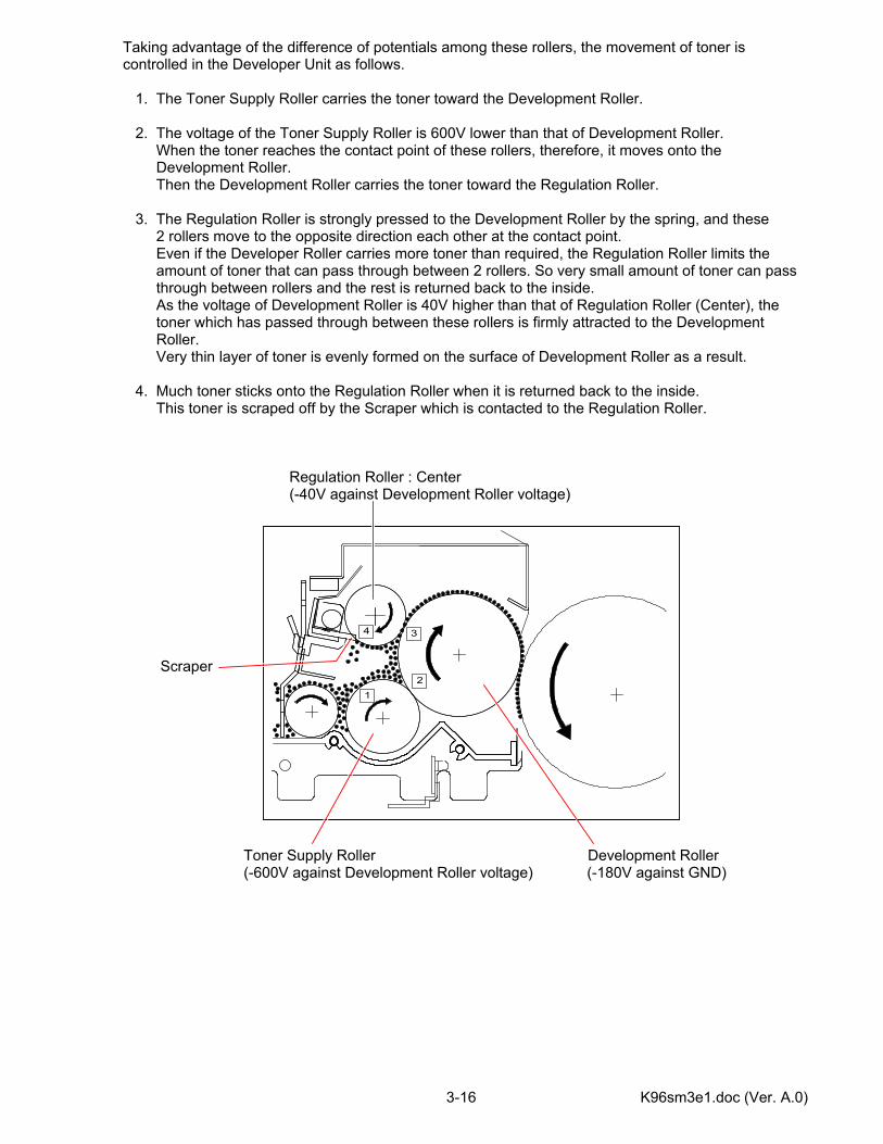
Taking advantage of the difference of potentials among these rollers, the movement of toner is controlled in the Developer Unit as follows. 1. The Toner Supply Roller carries the toner toward the Development Roller. 2. The voltage of the Toner Supply Roller is 600V lower than that of Development Roller. When the toner reaches the contact point of these rollers, therefore, it moves onto the Development Roller. Then the Development Roller carries the toner toward the Regulation Roller. 3. The Regulation Roller is strongly pressed to the Development Roller by the spring, and these 2 rollers move to the opposite direction each other at the contact point. Even if the Developer Roller carries more toner than required, the Regulation Roller limits the amount of toner that can pass through between 2 rollers. So very small amount of toner can pass through between rollers and the rest is returned back to the inside. As the voltage of Development Roller is 40V higher than that of Regulation Roller (Center), the toner which has passed through between these rollers is firmly attracted to the Development Roller. Very thin layer of toner is evenly formed on the surface of Development Roller as a result. 4. Much toner sticks onto the Regulation Roller when it is returned back to the inside. This toner is scraped off by the Scraper which is contacted to the Regulation Roller. Regulation Roller : Center (-40V against Development Roller voltage) Scraper Toner Supply Roller Development Roller (-600V against Development Roller voltage) (-180V against GND)
12
34
K96sm3e1.doc (Ver. A.0) 3-17
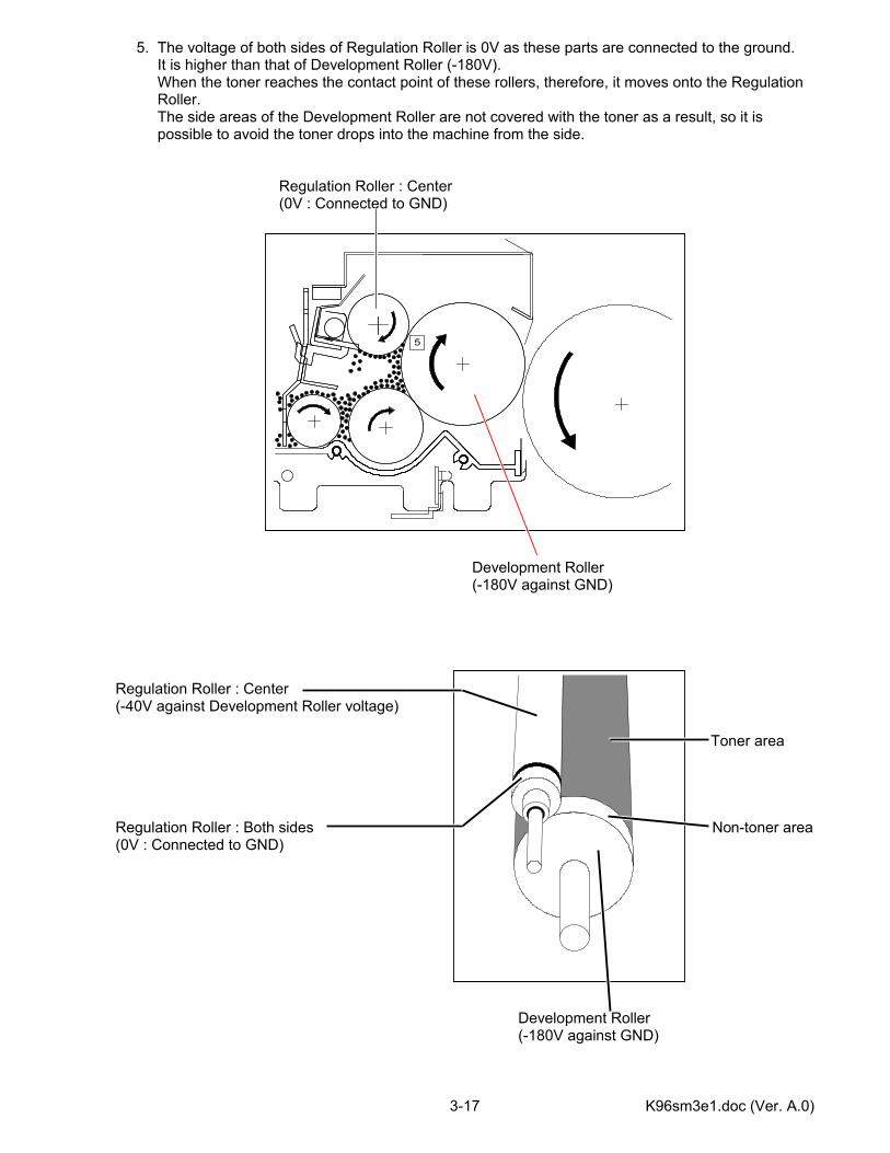
5. The voltage of both sides of Regulation Roller is 0V as these parts are connected to the ground. It is higher than that of Development Roller (-180V). When the toner reaches the contact point of these rollers, therefore, it moves onto the Regulation Roller. The side areas of the Development Roller are not covered with the toner as a result, so it is possible to avoid the toner drops into the machine from the side. Regulation Roller : Center (0V : Connected to GND) Development Roller (-180V against GND) Regulation Roller : Center (-40V against Development Roller voltage) Toner area Regulation Roller : Both sides Non-toner area (0V : Connected to GND) Development Roller (-180V against GND)
5
K96sm3e1.doc (Ver. A.0) 3-18
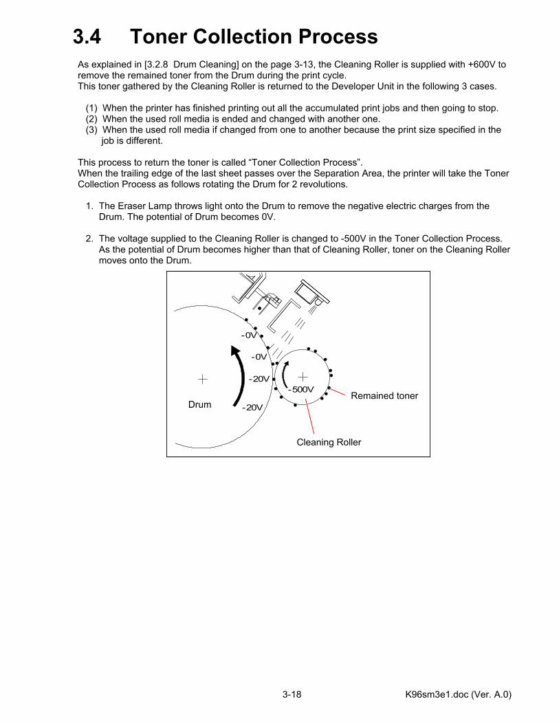
3.4 Toner Collection Process As explained in [3.2.8 Drum Cleaning] on the page 3-13, the Cleaning Roller is supplied with +600V to remove the remained toner from the Drum during the print cycle. This toner gathered by the Cleaning Roller is returned to the Developer Unit in the following 3 cases. (1) When the printer has finished printing out all the accumulated print jobs and then going to stop. (2) When the used roll media is ended and changed with another one. (3) When the used roll media if changed from one to another because the print size specified in the job is different. This process to return the toner is called “Toner Collection Process”. When the trailing edge of the last sheet passes over the Separation Area, the printer will take the Toner Collection Process as follows rotating the Drum for 2 revolutions. 1. The Eraser Lamp throws light onto the Drum to remove the negative electric charges from the Drum. The potential of Drum becomes 0V. 2. The voltage supplied to the Cleaning Roller is changed to -500V in the Toner Collection Process. As the potential of Drum becomes higher than that of Cleaning Roller, toner on the Cleaning Roller moves onto the Drum.
-20V
-20V
-0V
-500V
-0V
Remained toner
Cleaning Roller
Drum
K96sm3e1.doc (Ver. A.0) 3-19
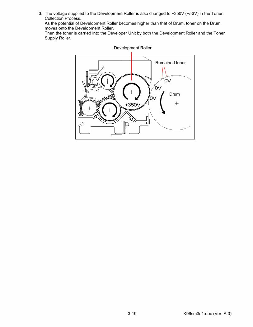
3. The voltage supplied to the Development Roller is also changed to +350V (+/-3V) in the Toner Collection Process. As the potential of Development Roller becomes higher than that of Drum, toner on the Drum moves onto the Development Roller. Then the toner is carried into the Developer Unit by both the Development Roller and the Toner Supply Roller. Development Roller
0V
+350V
0V
0V
Remained toner
Drum

K96sm3e1.doc (Ver. A.0) 3-20
Voltages supplied to Regulation Roller and Toner Supply Roller are changed also as follows. Regulation Roller : Both sides Regulation Roller : Center (0V : Connected to GND) (-40V against Development Roller voltage) Development Roller Toner Supply Roller (+350V against GND) (-600V against Development Roller voltage)
Reference
Name of roller Supplied voltage Developer Roller +350V +/-3V against the ground Toner Supply Roller -40V against the voltage of Development Roller Regulation Roller (Center)
0V (Connected to the ground)
Regulation Roller (Both sides)
-600V against the voltage of Development Roller
K96sm4e1-1.doc (Ver. A.0)
Chapter 4
Electrical System Page 4.1 General Information 4- 1 4.2 Electric Assembly Location/Function 4- 2 4.2.1 Printed Circuit Board 4- 2 4.2.2 Fans 4- 4 4.2.3 Motors & Clutches 4- 6 4.2.4 Heaters, SSR, Relays, Thermistors & Thermostats 4- 8 4.2.5 Circuit Breaker. Line Filter, Micro Switches, Switches & Counter 4-10 4.2.6 Sensors 4-12 4.2.7 Cassette 4-15 4.3 Checking & Adjustment of Analog Output from HVP 4-22 4.3.1 Situations necessary to check the analog output 4-22 4.3.2 Checking & Adjustment of Analog Current for Image Corona 4-23 4.3.3 Checking & Adjustment of Analog Current for Transfer Corona 4-25 4.3.4 Checking & Adjustment of AC Component for Separation Corona 4-27 4.3.5 Checking & Adjustment of DC Component for Separation Corona 4-29 4.3.6 Checking & Adjustment of Negative Developer Bias for Development Roller 4-31 4.3.7 Checking & Adjustment of Negative Developer Bias for Toner Supply Roller 4-33 4.3.8 Checking & Adjustment of Negative Developer Bias for Regulation Roller 4-35 4.3.9 Checking & Adjustment of Positive Developer Bias for Development Roller 4-37 4.3.10 Checking & Adjustment of Positive Cleaning Roller Bias (Print Cycle) 4-39 4.3.11 Checking & Adjustment of Negative Cleaning Roller Bias (Toner Collection Process) 4-41
K96sm4e1-1.doc (Ver. A.0) 4-1
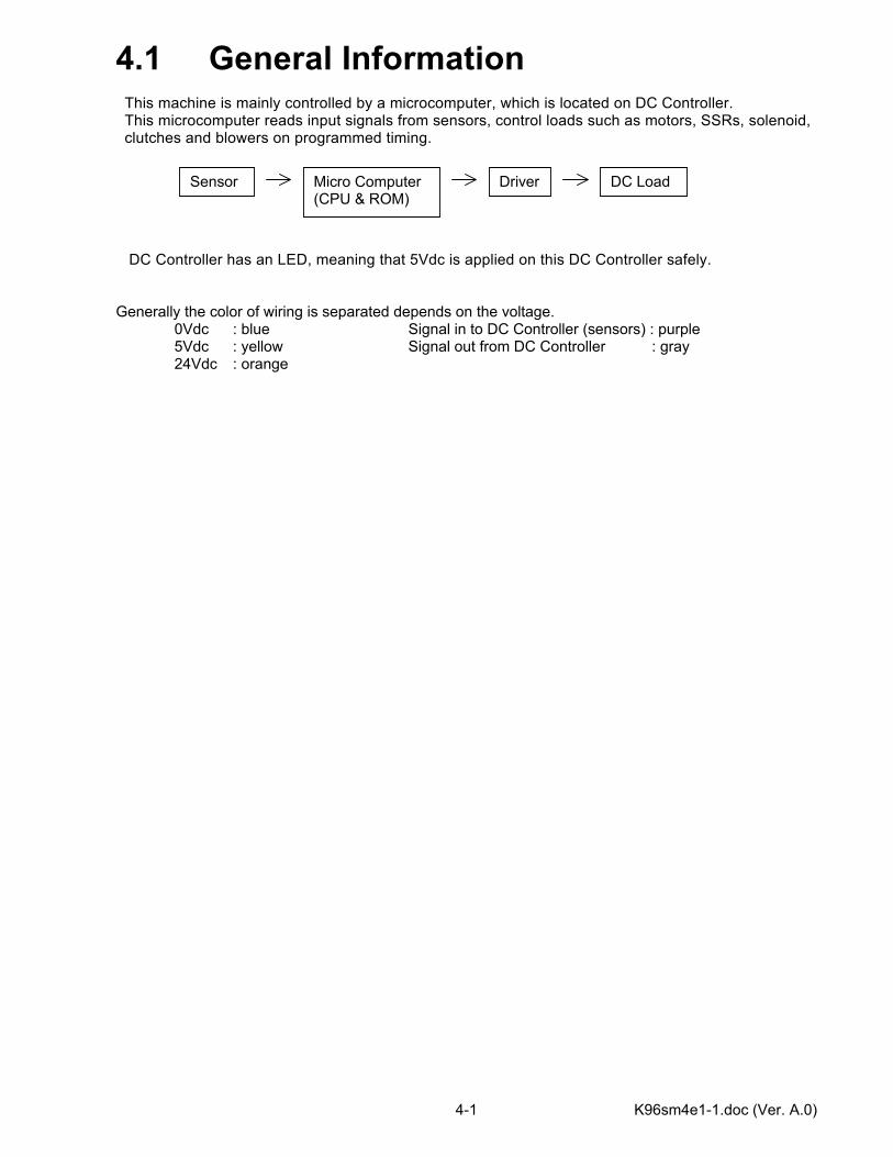
4.1 General Information This machine is mainly controlled by a microcomputer, which is located on DC Controller. This microcomputer reads input signals from sensors, control loads such as motors, SSRs, solenoid, clutches and blowers on programmed timing. DC Controller has an LED, meaning that 5Vdc is applied on this DC Controller safely. Generally the color of wiring is separated depends on the voltage. 0Vdc : blue Signal in to DC Controller (sensors) : purple 5Vdc : yellow Signal out from DC Controller : gray 24Vdc : orange
Sensor Micro Computer(CPU & ROM)
DC Load Driver
K96sm4e1-1.doc (Ver. A.0) 4-2
4.2 Electric Assembly Location/Function
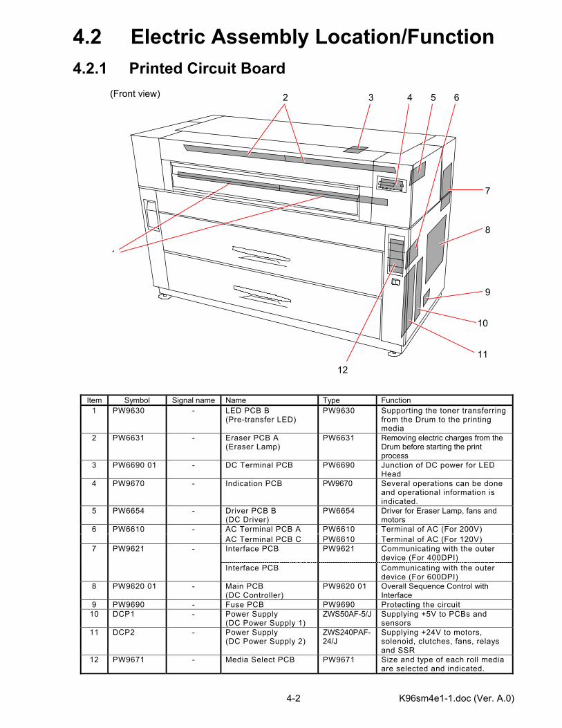
4.2.1 Printed Circuit Board (Front view)
Item Symbol Signal name Name Type Function 1 PW9630 - LED PCB B
(Pre-transfer LED) PW9630 Supporting the toner transferring
from the Drum to the printing media
2 PW6631 - Eraser PCB A (Eraser Lamp)
PW6631 Removing electric charges from the Drum before starting the print process
3 PW6690 01 - DC Terminal PCB PW6690 Junction of DC power for LED Head
4 PW9670 - Indication PCB PW9670 Several operations can be done and operational information is indicated.
5 PW6654 - Driver PCB B (DC Driver)
PW6654 Driver for Eraser Lamp, fans and motors
AC Terminal PCB A PW6610 Terminal of AC (For 200V) 6 PW6610 - AC Terminal PCB C PW6610 Terminal of AC (For 120V) Interface PCB PW9621 Communicating with the outer
device (For 400DPI) 7 PW9621 -
Interface PCB Communicating with the outer device (For 600DPI)
8 PW9620 01 - Main PCB (DC Controller)
PW9620 01 Overall Sequence Control with Interface
9 PW9690 - Fuse PCB PW9690 Protecting the circuit 10 DCP1 - Power Supply
(DC Power Supply 1) ZWS50AF-5/J Supplying +5V to PCBs and
sensors 11 DCP2 - Power Supply
(DC Power Supply 2) ZWS240PAF-24/J
Supplying +24V to motors, solenoid, clutches, fans, relays and SSR
12 PW9671 - Media Select PCB PW9671 Size and type of each roll media are selected and indicated.
4 32
1
5 6
7
8
9
10
1112
K96sm4e1-1.doc (Ver. A.0) 4-3
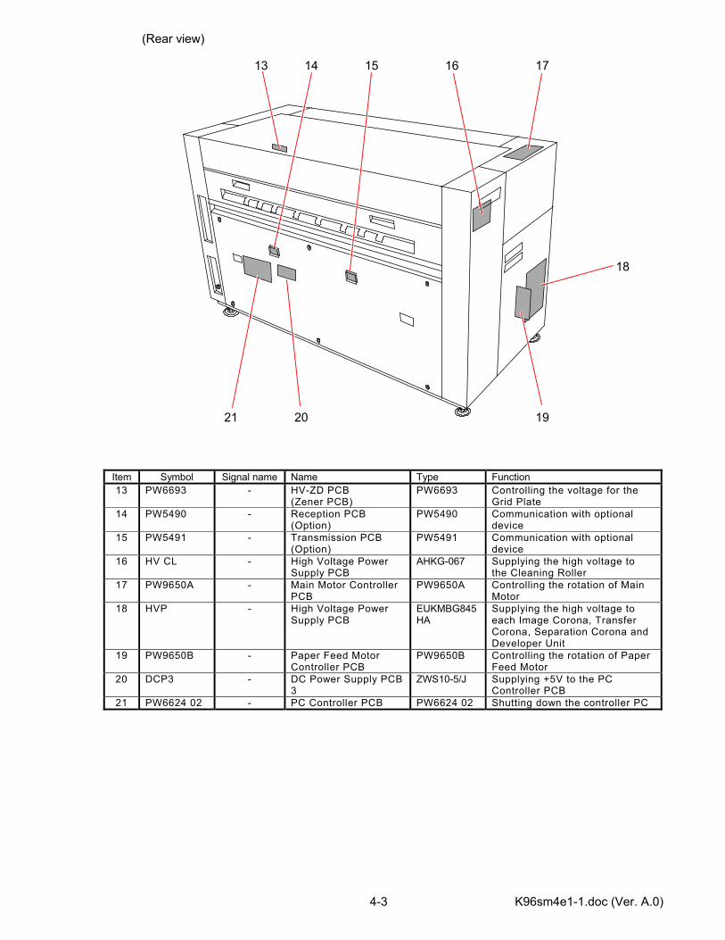
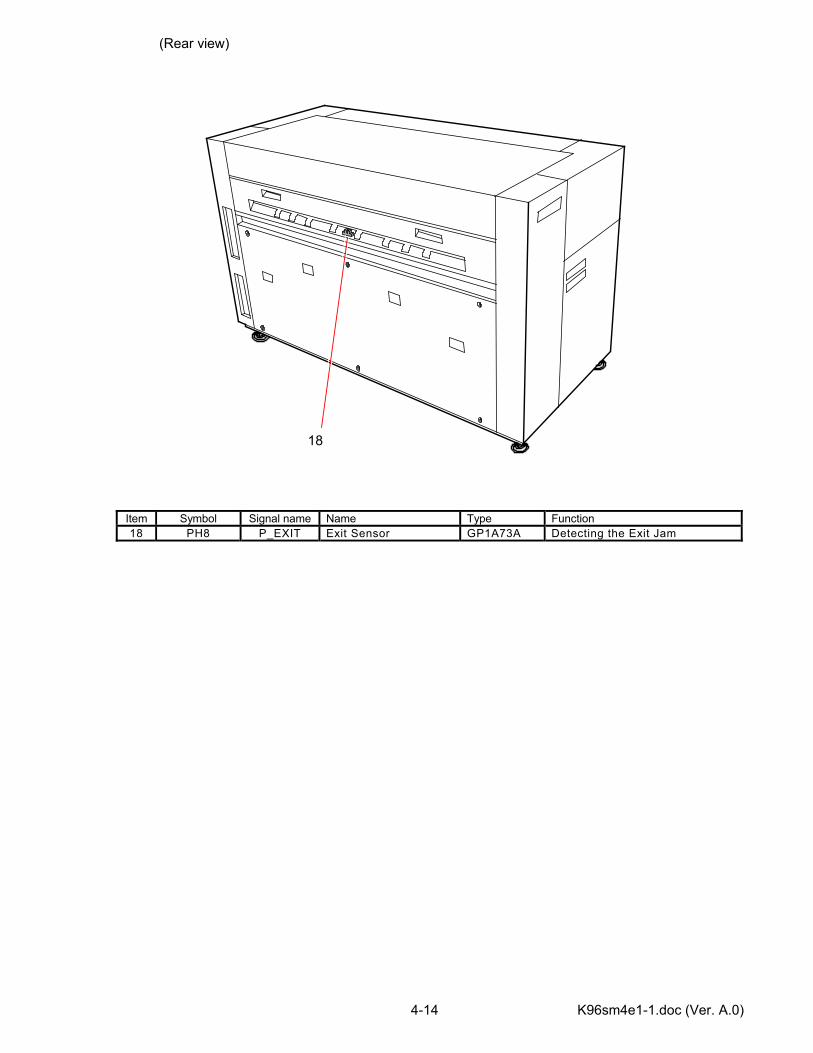
(Rear view)
Item Symbol Signal name Name Type Function 13 PW6693 - HV-ZD PCB
(Zener PCB) PW6693 Controlling the voltage for the
Grid Plate 14 PW5490 - Reception PCB
(Option) PW5490 Communication with optional
device 15 PW5491 - Transmission PCB
(Option) PW5491 Communication with optional
device 16 HV CL - High Voltage Power
Supply PCB AHKG-067 Supplying the high voltage to
the Cleaning Roller 17 PW9650A - Main Motor Controller
PCB PW9650A Controlling the rotation of Main
Motor 18 HVP - High Voltage Power
Supply PCB EUKMBG845HA
Supplying the high voltage to each Image Corona, Transfer Corona, Separation Corona and Developer Unit
19 PW9650B - Paper Feed Motor Controller PCB
PW9650B Controlling the rotation of Paper Feed Motor
20 DCP3 - DC Power Supply PCB 3
ZWS10-5/J Supplying +5V to the PC Controller PCB
21 PW6624 02 - PC Controller PCB PW6624 02 Shutting down the controller PC
14 15 16 17
18
19 2021
13
K96sm4e1-1.doc (Ver. A.0) 4-4
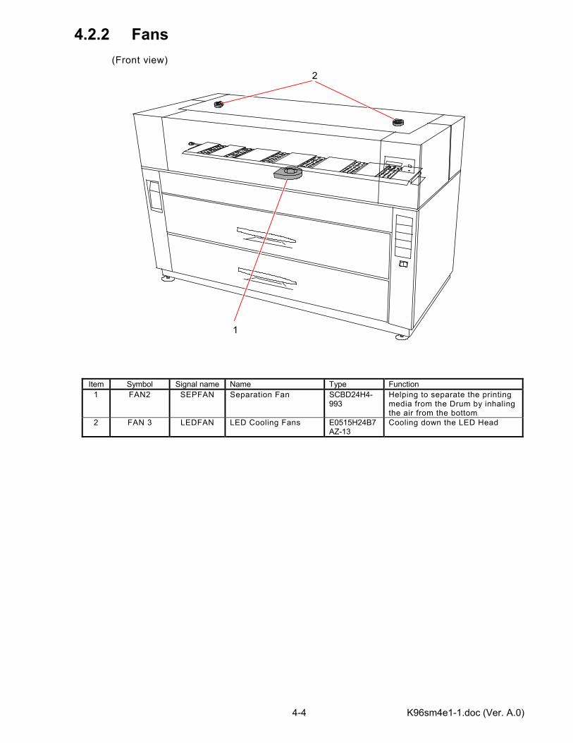
4.2.2 Fans (Front view)
Item Symbol Signal name Name Type Function 1 FAN2 SEPFAN Separation Fan SCBD24H4-
993 Helping to separate the printing media from the Drum by inhaling the air from the bottom
2 FAN 3 LEDFAN LED Cooling Fans E0515H24B7AZ-13
Cooling down the LED Head
1
2
K96sm4e1-1.doc (Ver. A.0) 4-5
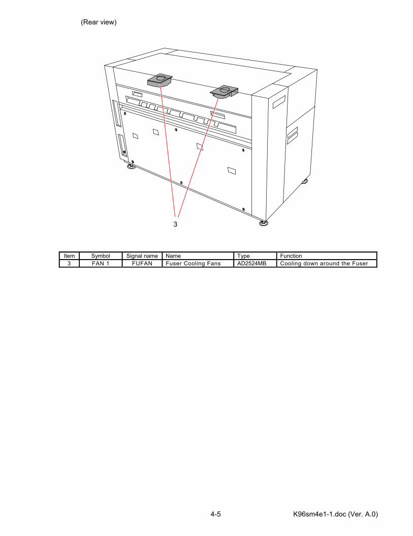
(Rear view)
Item Symbol Signal name Name Type Function 3 FAN 1 FUFAN Fuser Cooling Fans AD2524MB Cooling down around the Fuser
3
K96sm4e1-1.doc (Ver. A.0) 4-6
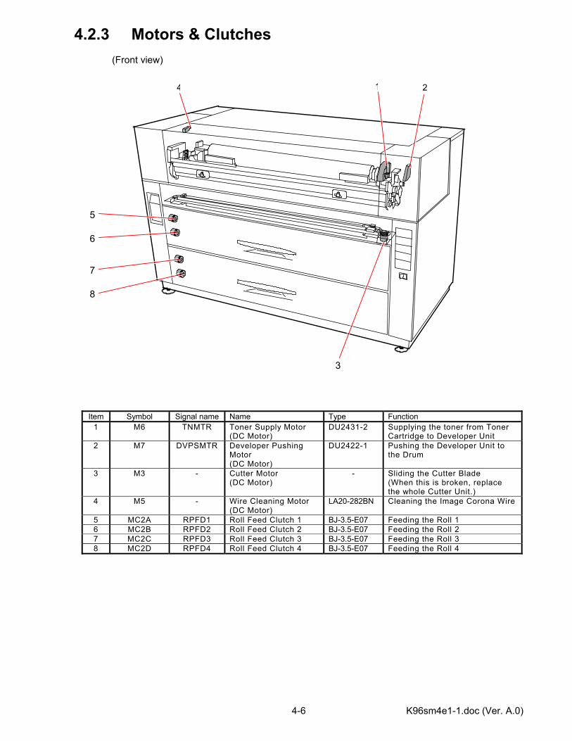
4.2.3 Motors & Clutches (Front view)
Item Symbol Signal name Name Type Function 1 M6 TNMTR Toner Supply Motor
(DC Motor) DU2431-2 Supplying the toner from Toner
Cartridge to Developer Unit 2 M7 DVPSMTR Developer Pushing
Motor (DC Motor)
DU2422-1 Pushing the Developer Unit to the Drum
3 M3 - Cutter Motor (DC Motor)
- Sliding the Cutter Blade (When this is broken, replace the whole Cutter Unit.)
4 M5 - Wire Cleaning Motor (DC Motor)
LA20-282BN Cleaning the Image Corona Wire
5 MC2A RPFD1 Roll Feed Clutch 1 BJ-3.5-E07 Feeding the Roll 1 6 MC2B RPFD2 Roll Feed Clutch 2 BJ-3.5-E07 Feeding the Roll 2 7 MC2C RPFD3 Roll Feed Clutch 3 BJ-3.5-E07 Feeding the Roll 3 8 MC2D RPFD4 Roll Feed Clutch 4 BJ-3.5-E07 Feeding the Roll 4
1 2
3
5
6
7
8
4
K96sm4e1-1.doc (Ver. A.0) 4-7
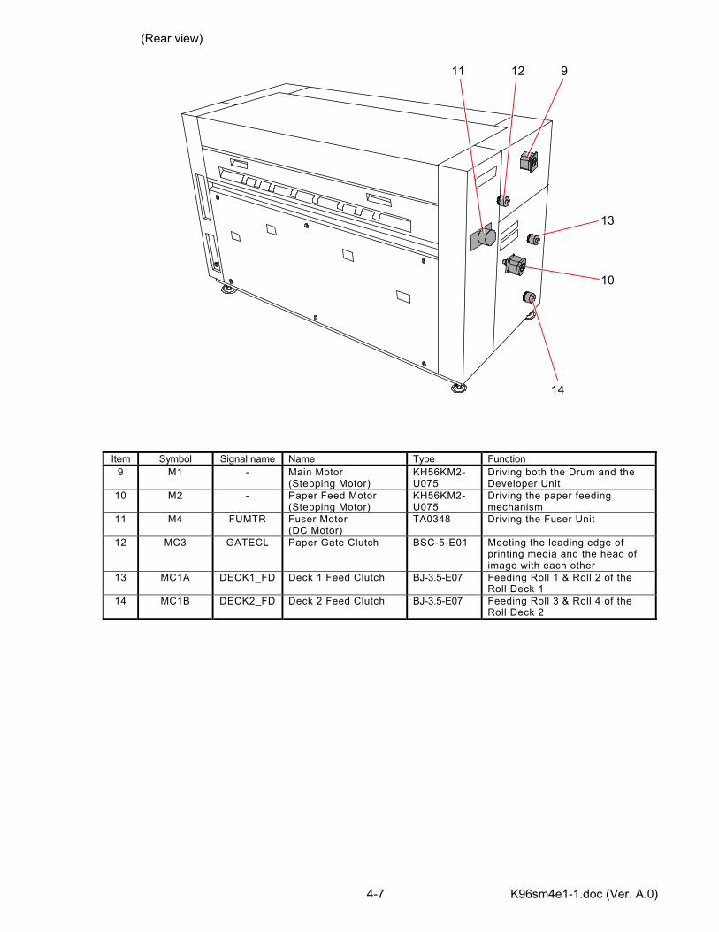
(Rear view)
Item Symbol Signal name Name Type Function 9 M1 - Main Motor
(Stepping Motor) KH56KM2-U075
Driving both the Drum and the Developer Unit
10 M2 - Paper Feed Motor (Stepping Motor)
KH56KM2-U075
Driving the paper feeding mechanism
11 M4 FUMTR Fuser Motor (DC Motor)
TA0348 Driving the Fuser Unit
12 MC3 GATECL Paper Gate Clutch BSC-5-E01 Meeting the leading edge of printing media and the head of image with each other
13 MC1A DECK1_FD Deck 1 Feed Clutch BJ-3.5-E07 Feeding Roll 1 & Roll 2 of the Roll Deck 1
14 MC1B DECK2_FD Deck 2 Feed Clutch BJ-3.5-E07 Feeding Roll 3 & Roll 4 of the Roll Deck 2
9
10
11
13
14
12
K96sm4e1-1.doc (Ver. A.0) 4-8
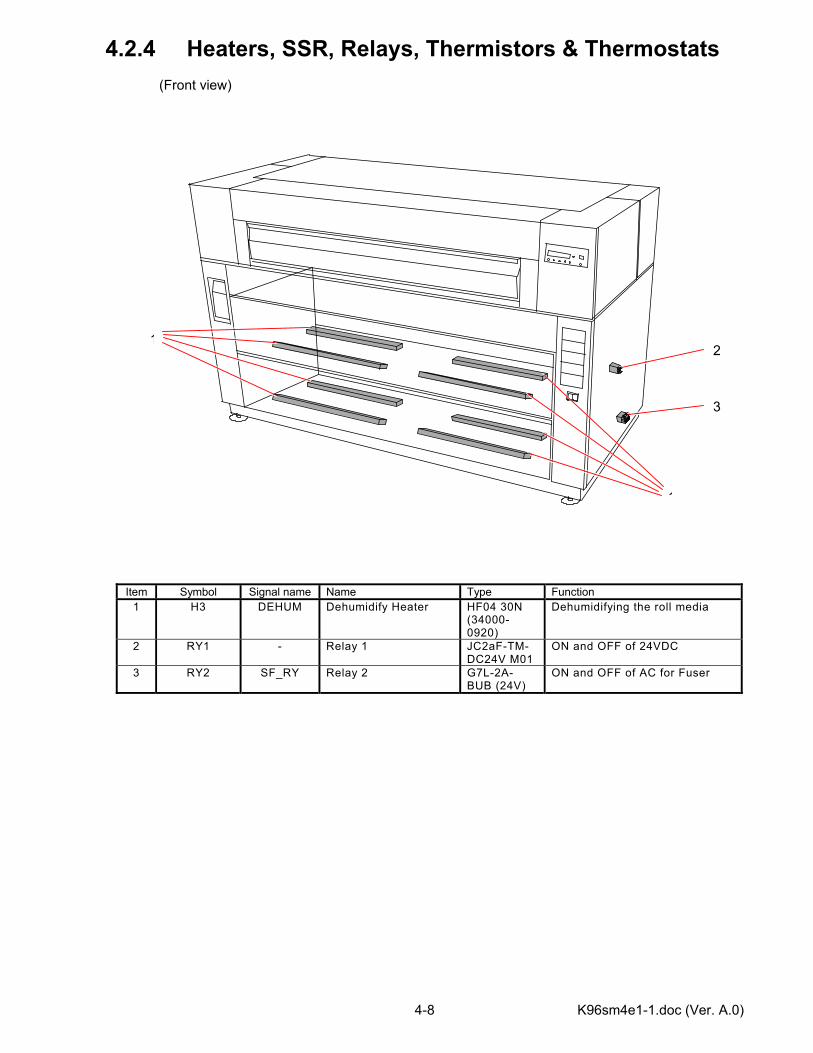
4.2.4 Heaters, SSR, Relays, Thermistors & Thermostats (Front view)
Item Symbol Signal name Name Type Function 1 H3 DEHUM Dehumidify Heater HF04 30N
(34000-0920)
Dehumidifying the roll media
2 RY1 - Relay 1 JC2aF-TM-DC24V M01
ON and OFF of 24VDC
3 RY2 SF_RY Relay 2 G7L-2A-BUB (24V)
ON and OFF of AC for Fuser
12
3
1
K96sm4e1-1.doc (Ver. A.0) 4-9
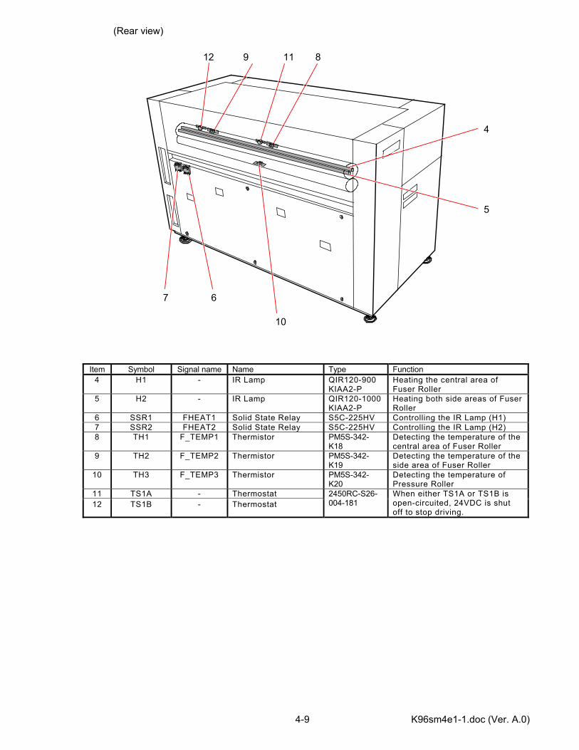
(Rear view)
Item Symbol Signal name Name Type Function 4 H1 - IR Lamp QIR120-900
KIAA2-P Heating the central area of Fuser Roller
5 H2 - IR Lamp QIR120-1000 KIAA2-P
Heating both side areas of Fuser Roller
6 SSR1 FHEAT1 Solid State Relay S5C-225HV Controlling the IR Lamp (H1) 7 SSR2 FHEAT2 Solid State Relay S5C-225HV Controlling the IR Lamp (H2) 8 TH1 F_TEMP1 Thermistor PM5S-342-
K18 Detecting the temperature of the central area of Fuser Roller
9 TH2 F_TEMP2 Thermistor PM5S-342-K19
Detecting the temperature of the side area of Fuser Roller
10 TH3 F_TEMP3 Thermistor PM5S-342-K20
Detecting the temperature of Pressure Roller
11 TS1A - Thermostat 12 TS1B - Thermostat
2450RC-S26-004-181
When either TS1A or TS1B is open-circuited, 24VDC is shut off to stop driving.
4
5
7 6
10
811912
K96sm4e1-1.doc (Ver. A.0) 4-10
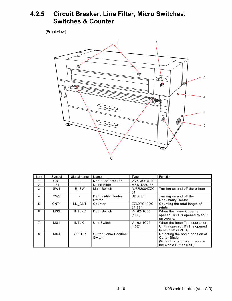
4.2.5 Circuit Breaker. Line Filter, Micro Switches, Switches & Counter (Front view)
Item Symbol Signal name Name Type Function 1 CB1 - Non Fuse Breaker W28-XQ1A-20 2 LF1 - Noise Filter MBS-1220-22 3 SW1 R_SW Main Switch AJ8R2004ZZC
01 Turning on and off the printer
4 SW2 - Dehumidify Heater Switch
SDDJE1 Turning on and off the Dehumidify Heater
5 CNT1 LN_CNT Counter E760PC10DC24-551
Counting the total length of prints
6 MS2 INTLK2 Door Switch V-162-1C25 (10E)
When the Toner Cover is opened, RY1 is opened to shut off 24VDC.
7 MS1 INTLK1 Unit Switch V-162-1C25 (10E)
When the Inner Transportation Unit is opened, RY1 is opened to shut off 24VDC.
8 MS4 CUTHP Cutter Home Position Switch
- Detecting the home position of Cutter Blade (When this is broken, replace the whole Cutter Unit.)
5
1
2
3
4
6 7
8
K96sm4e1-1.doc (Ver. A.0) 4-11
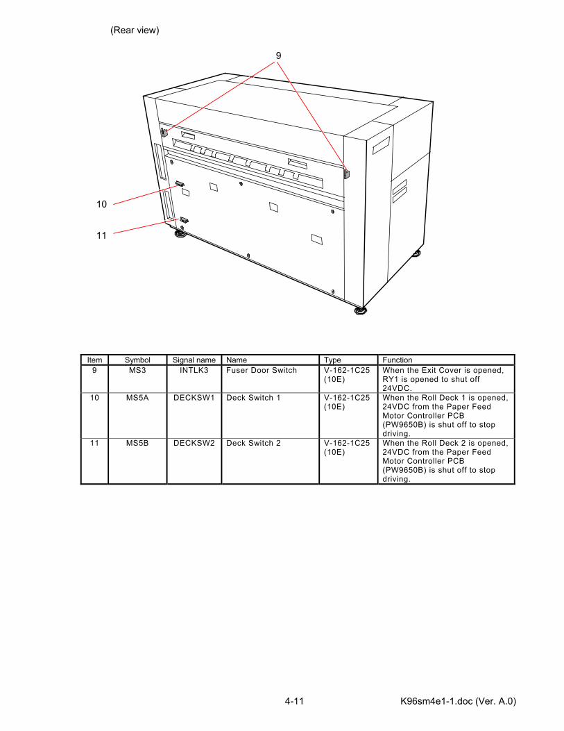
(Rear view)
Item Symbol Signal name Name Type Function 9 MS3 INTLK3 Fuser Door Switch V-162-1C25
(10E) When the Exit Cover is opened, RY1 is opened to shut off 24VDC.
10 MS5A DECKSW1 Deck Switch 1 V-162-1C25 (10E)
When the Roll Deck 1 is opened, 24VDC from the Paper Feed Motor Controller PCB (PW9650B) is shut off to stop driving.
11 MS5B DECKSW2 Deck Switch 2 V-162-1C25 (10E)
When the Roll Deck 2 is opened, 24VDC from the Paper Feed Motor Controller PCB (PW9650B) is shut off to stop driving.
9
10
11
K96sm4e1-1.doc (Ver. A.0) 4-12
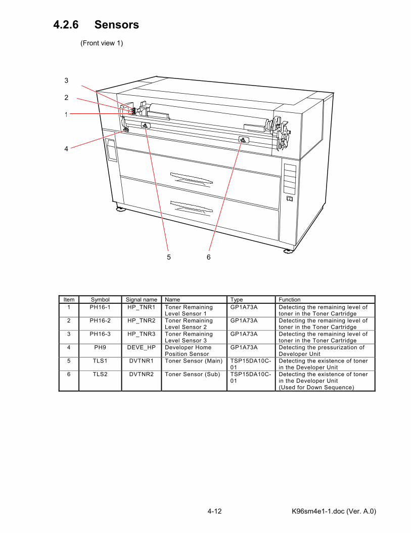
4.2.6 Sensors (Front view 1)
Item Symbol Signal name Name Type Function 1 PH16-1 HP_TNR1 Toner Remaining
Level Sensor 1 GP1A73A Detecting the remaining level of
toner in the Toner Cartridge 2 PH16-2 HP_TNR2 Toner Remaining
Level Sensor 2 GP1A73A Detecting the remaining level of
toner in the Toner Cartridge 3 PH16-3 HP_TNR3 Toner Remaining
Level Sensor 3 GP1A73A Detecting the remaining level of
toner in the Toner Cartridge 4 PH9 DEVE_HP Developer Home
Position Sensor GP1A73A Detecting the pressurization of
Developer Unit 5 TLS1 DVTNR1 Toner Sensor (Main) TSP15DA10C-
01 Detecting the existence of toner in the Developer Unit
6 TLS2 DVTNR2 Toner Sensor (Sub) TSP15DA10C-01
Detecting the existence of toner in the Developer Unit (Used for Down Sequence)
1
4
5 6
3
2
K96sm4e1-1.doc (Ver. A.0) 4-13
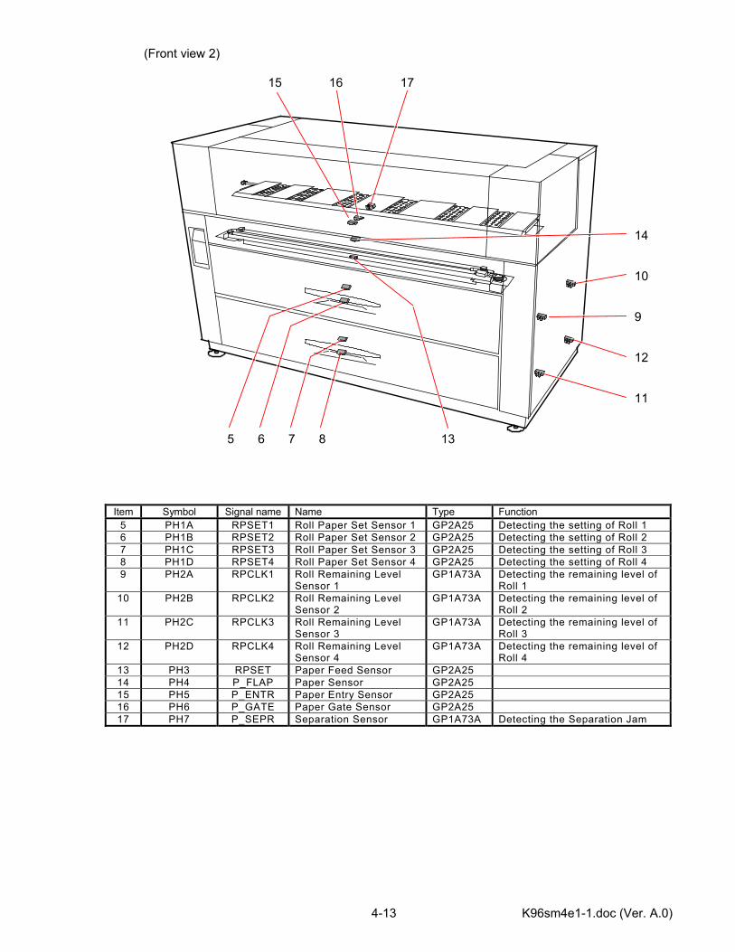
(Front view 2)
Item Symbol Signal name Name Type Function 5 PH1A RPSET1 Roll Paper Set Sensor 1 GP2A25 Detecting the setting of Roll 1 6 PH1B RPSET2 Roll Paper Set Sensor 2 GP2A25 Detecting the setting of Roll 2 7 PH1C RPSET3 Roll Paper Set Sensor 3 GP2A25 Detecting the setting of Roll 3 8 PH1D RPSET4 Roll Paper Set Sensor 4 GP2A25 Detecting the setting of Roll 4 9 PH2A RPCLK1 Roll Remaining Level
Sensor 1 GP1A73A Detecting the remaining level of
Roll 1 10 PH2B RPCLK2 Roll Remaining Level
Sensor 2 GP1A73A Detecting the remaining level of
Roll 2 11 PH2C RPCLK3 Roll Remaining Level
Sensor 3 GP1A73A Detecting the remaining level of
Roll 3 12 PH2D RPCLK4 Roll Remaining Level
Sensor 4 GP1A73A Detecting the remaining level of
Roll 4 13 PH3 RPSET Paper Feed Sensor GP2A25 14 PH4 P_FLAP Paper Sensor GP2A25 15 PH5 P_ENTR Paper Entry Sensor GP2A25 16 PH6 P_GATE Paper Gate Sensor GP2A25 17 PH7 P_SEPR Separation Sensor GP1A73A Detecting the Separation Jam
8
10
9
12
7 5 6
11
13
14
15 16 17
K96sm4e1-1.doc (Ver. A.0) 4-14
(Rear view)
Item Symbol Signal name Name Type Function 18 PH8 P_EXIT Exit Sensor GP1A73A Detecting the Exit Jam
18

K96sm4e1-1.doc (Ver. A.0) 4-15
4.2.7 Cassette (Upper Cassette)
Item Symbol Signal name Name Type Function 1 PW9651 - Cassette Driver PCB Controlling the Cassette 1 2 M8A Lift Up Motor 1 DU2421-1 Moving up the tray of the
Cassette 1 3 PH14A CS1_PL1 Cassette 1Paper
Remaining Level Sensor 1 GP1A73A Detecting the remaining level of
paper in the Cassette 1 4 PH15A CS1_PL2 Cassette 1Paper
Remaining Level Sensor 2 GP1A73A Detecting the remaining level of
paper in the Cassette 1 5 MC4A CSCL1 Cassette 1 Feed Clutch M1C5NE-
45 Driving the feeding rollers in the Cassette 1
3
1
45 2
K96sm4e1-1.doc (Ver. A.0) 4-16
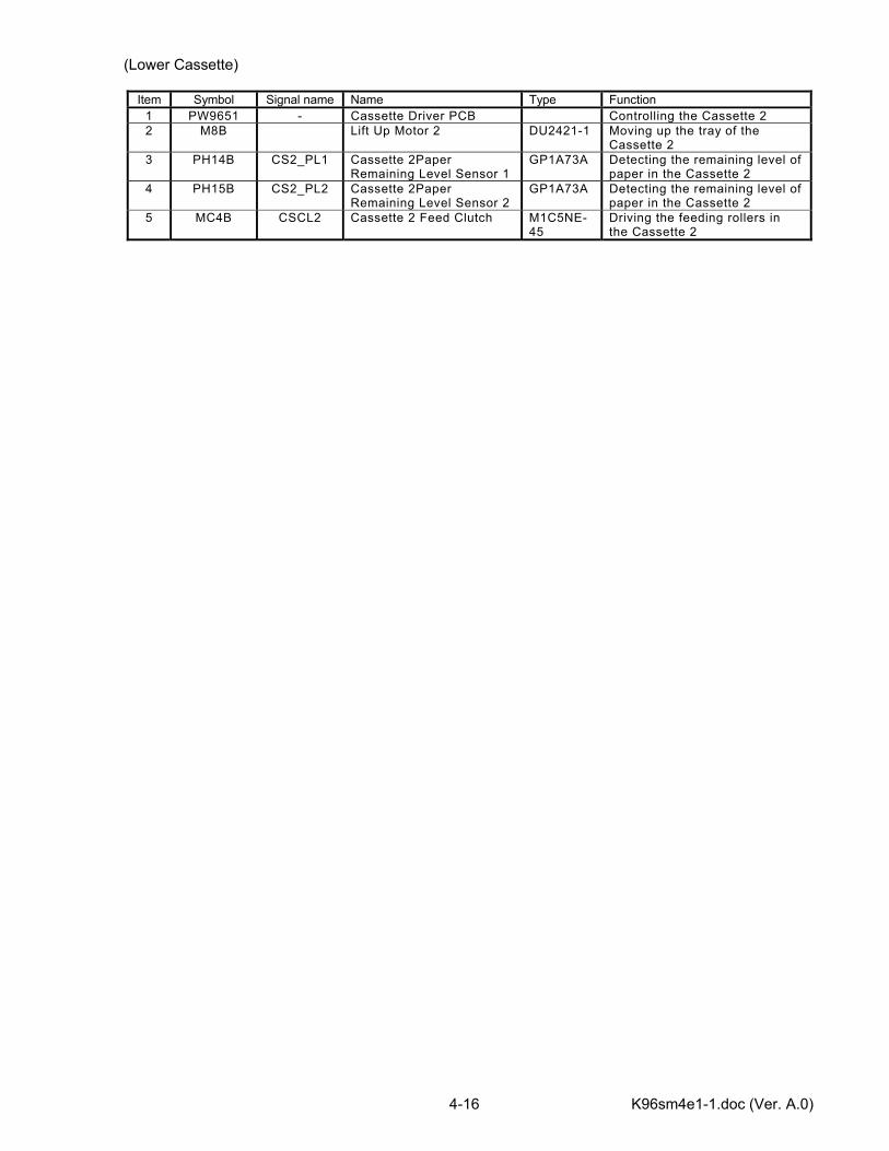
(Lower Cassette)
Item Symbol Signal name Name Type Function 1 PW9651 - Cassette Driver PCB Controlling the Cassette 2 2 M8B Lift Up Motor 2 DU2421-1 Moving up the tray of the
Cassette 2 3 PH14B CS2_PL1 Cassette 2Paper
Remaining Level Sensor 1 GP1A73A Detecting the remaining level of
paper in the Cassette 2 4 PH15B CS2_PL2 Cassette 2Paper
Remaining Level Sensor 2 GP1A73A Detecting the remaining level of
paper in the Cassette 2 5 MC4B CSCL2 Cassette 2 Feed Clutch M1C5NE-
45 Driving the feeding rollers in the Cassette 2
K96sm4e1-1.doc (Ver. A.0) 4-17
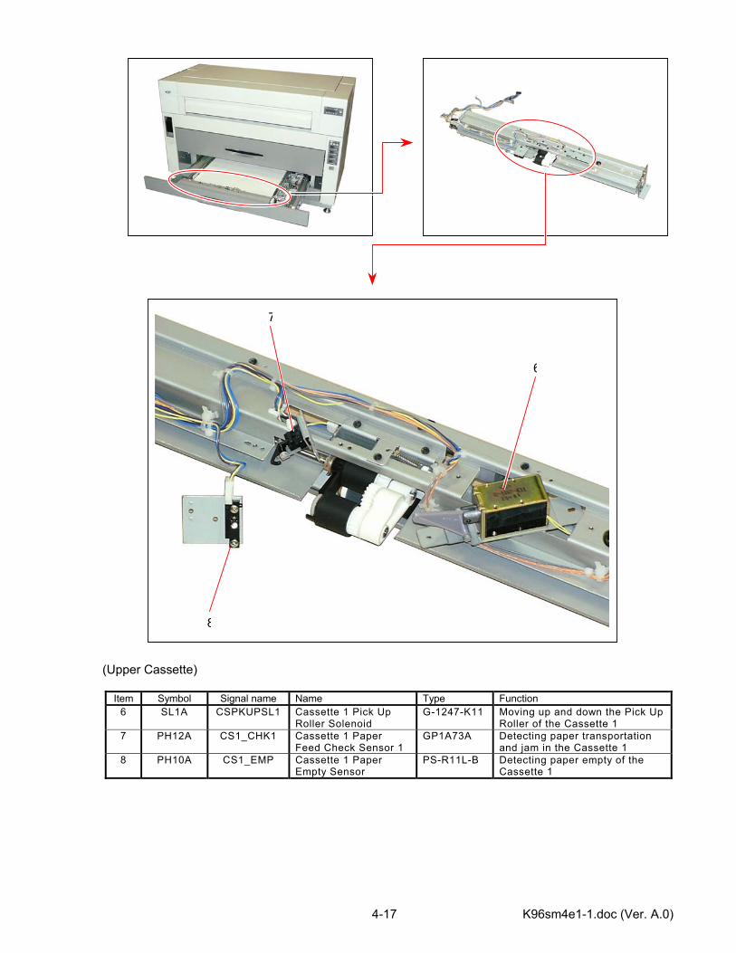
(Upper Cassette)
Item Symbol Signal name Name Type Function 6 SL1A CSPKUPSL1 Cassette 1 Pick Up
Roller Solenoid G-1247-K11 Moving up and down the Pick Up
Roller of the Cassette 1 7 PH12A CS1_CHK1 Cassette 1 Paper
Feed Check Sensor 1 GP1A73A Detecting paper transportation
and jam in the Cassette 1 8 PH10A CS1_EMP Cassette 1 Paper
Empty Sensor PS-R11L-B Detecting paper empty of the
Cassette 1
6
7
8
K96sm4e1-1.doc (Ver. A.0) 4-18
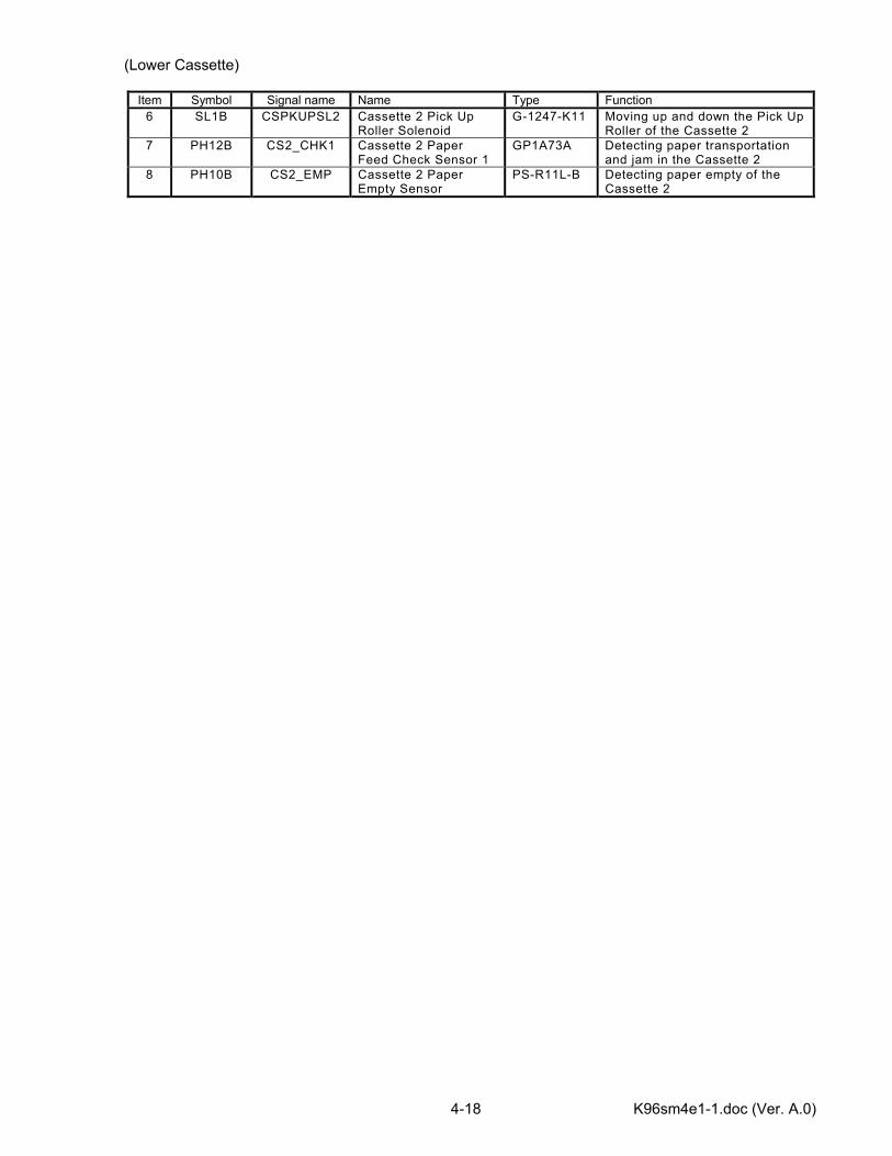
(Lower Cassette)
Item Symbol Signal name Name Type Function 6 SL1B CSPKUPSL2 Cassette 2 Pick Up
Roller Solenoid G-1247-K11 Moving up and down the Pick Up
Roller of the Cassette 2 7 PH12B CS2_CHK1 Cassette 2 Paper
Feed Check Sensor 1 GP1A73A Detecting paper transportation
and jam in the Cassette 2 8 PH10B CS2_EMP Cassette 2 Paper
Empty Sensor PS-R11L-B Detecting paper empty of the
Cassette 2
K96sm4e1-1.doc (Ver. A.0) 4-19
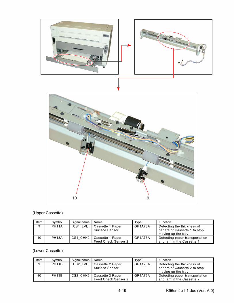
(Upper Cassette)
Item Symbol Signal name Name Type Function 9 PH11A CS1_LVL Cassette 1 Paper
Surface Sensor GP1A73A Detecting the thickness of
papers of Cassette 1 to stop moving up the tray
10 PH13A CS1_CHK2 Cassette 1 Paper Feed Check Sensor 2
GP1A73A Detecting paper transportation and jam in the Cassette 1
(Lower Cassette)
Item Symbol Signal name Name Type Function 9 PH11B CS2_LVL Cassette 2 Paper
Surface Sensor GP1A73A Detecting the thickness of
papers of Cassette 2 to stop moving up the tray
10 PH13B CS2_CHK2 Cassette 2 Paper Feed Check Sensor 2
GP1A73A Detecting paper transportation and jam in the Cassette 2
10 9
K96sm4e1-1.doc (Ver. A.0) 4-20
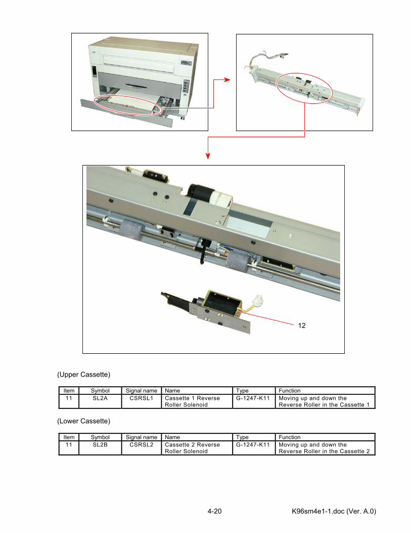
(Upper Cassette)
Item Symbol Signal name Name Type Function 11 SL2A CSRSL1 Cassette 1 Reverse
Roller Solenoid G-1247-K11 Moving up and down the
Reverse Roller in the Cassette 1 (Lower Cassette)
Item Symbol Signal name Name Type Function 11 SL2B CSRSL2 Cassette 2 Reverse
Roller Solenoid G-1247-K11 Moving up and down the
Reverse Roller in the Cassette 2
12
K96sm4e1-1.doc (Ver. A.0) 4-21
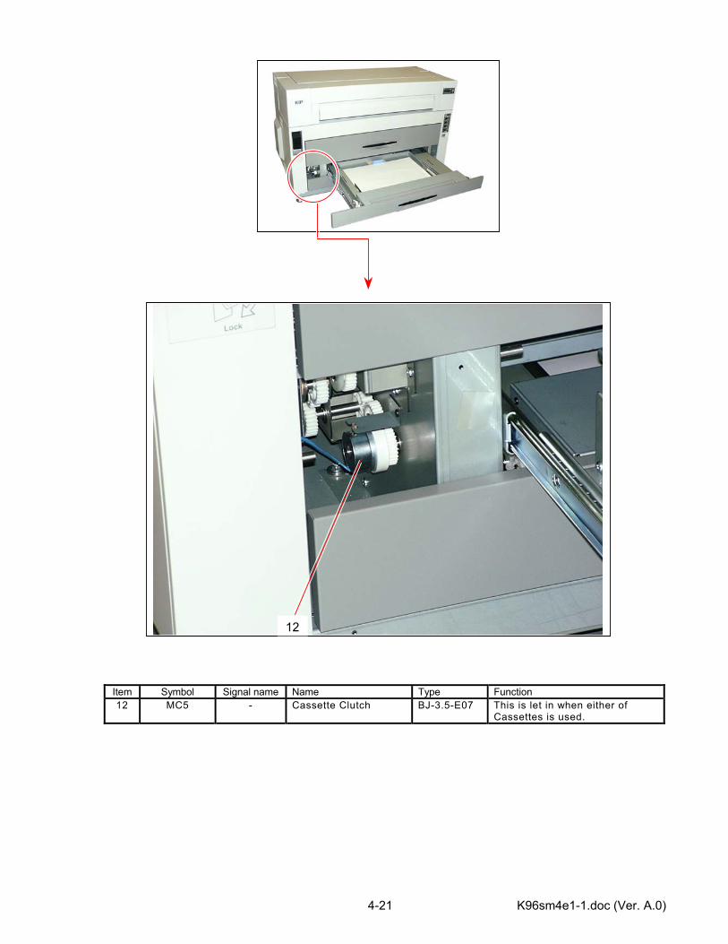
Item Symbol Signal name Name Type Function 12 MC5 - Cassette Clutch BJ-3.5-E07 This is let in when either of
Cassettes is used.
12
K96sm4e1-1.doc (Ver. A.0) 4-22
4.3 Checking & Adjustment of Analog Output from HVP
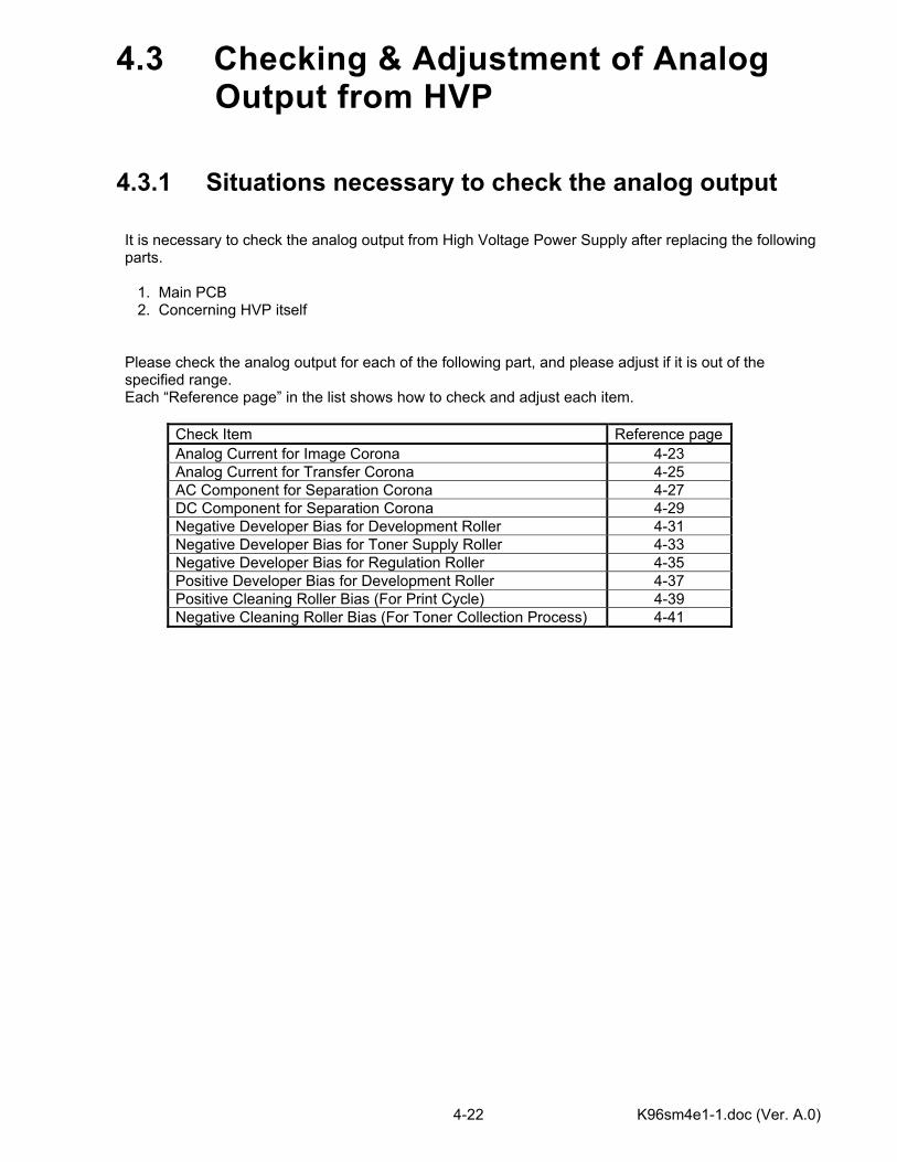
4.3.1 Situations necessary to check the analog output It is necessary to check the analog output from High Voltage Power Supply after replacing the following parts. 1. Main PCB 2. Concerning HVP itself Please check the analog output for each of the following part, and please adjust if it is out of the specified range. Each “Reference page” in the list shows how to check and adjust each item.
Check Item Reference pageAnalog Current for Image Corona 4-23 Analog Current for Transfer Corona 4-25 AC Component for Separation Corona 4-27 DC Component for Separation Corona 4-29 Negative Developer Bias for Development Roller 4-31 Negative Developer Bias for Toner Supply Roller 4-33 Negative Developer Bias for Regulation Roller 4-35 Positive Developer Bias for Development Roller 4-37 Positive Cleaning Roller Bias (For Print Cycle) 4-39 Negative Cleaning Roller Bias (For Toner Collection Process) 4-41
K96sm4e1-1.doc (Ver. A.0) 4-23
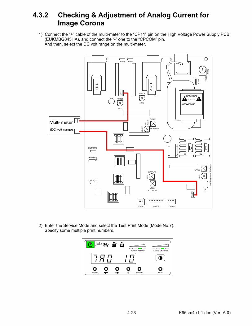
4.3.2 Checking & Adjustment of Analog Current for Image Corona 1) Connect the “+” cable of the multi-meter to the “CP11” pin on the High Voltage Power Supply PCB (EUKMBG845HA), and connect the “-” one to the “CPCOM” pin. And then, select the DC volt range on the multi-meter. 2) Enter the Service Mode and select the Test Print Mode (Mode No.7). Specify some multiple print numbers.
CAUTION!高圧注意
6606600010T
P1
2
TN
1
OUTPUT1
OUTPUT2
OUTPUT3
HV1
VR101
HV2
VR201
OUTPUT2
VR401
Don
'tTo
uch
VR
402
OUTPUT3
VR
501
OUTPUT1VR601
HV
3Vp-
p
VR302
VR
301
HV
3Fre
quen
cy
HV
3
HV
2
HV
3
HV
3DC
CN301 CN302 CN303C
P31
CP
CO
M
CP
33 VR
303
CP21 CP22
Multi-meterC
P11
(DC volt range)
MENU ENTER TEST
TONER REMAIN IMAGE DENSITY
job
*
K96sm4e1-1.doc (Ver. A.0) 4-24
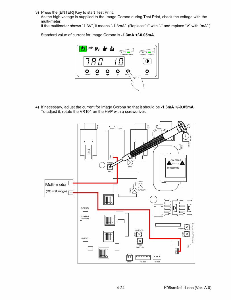
3) Press the [ENTER] Key to start Test Print. As the high voltage is supplied to the Image Corona during Test Print, check the voltage with the multi-meter. If the multimeter shows “1.3V”, it means “-1.3mA”. (Replace “+” with “-“ and replace “V” with “mA”.) Standard value of current for Image Corona is -1.3mA +/-0.05mA. 4) If necessary, adjust the current for Image Corona so that it should be -1.3mA +/-0.05mA. To adjust it, rotate the VR101 on the HVP with a screwdriver.
CAUTION!高圧注意
6606600010
TP
12
TN
1
OUTPUT1
OUTPUT2
OUTPUT3
HV1
VR101
HV2
VR201
OUTPUT2
VR401
Don
'tTo
uch
VR
402
OUTPUT3
VR
501
OUTPUT1VR601
HV
3Vp-
p
VR302
VR
301
HV
3Fre
quen
cy
HV
3
HV
2
HV
3
HV
3DC
CN301 CN302 CN303
CP
31
CP
CO
M
CP
33 VR
303
CP21 CP22
Multi-meter
CP
11
(DC volt range)
MENU ENTER TEST
TONER REMAIN IMAGE DENSITY
job
*
K96sm4e1-1.doc (Ver. A.0) 4-25
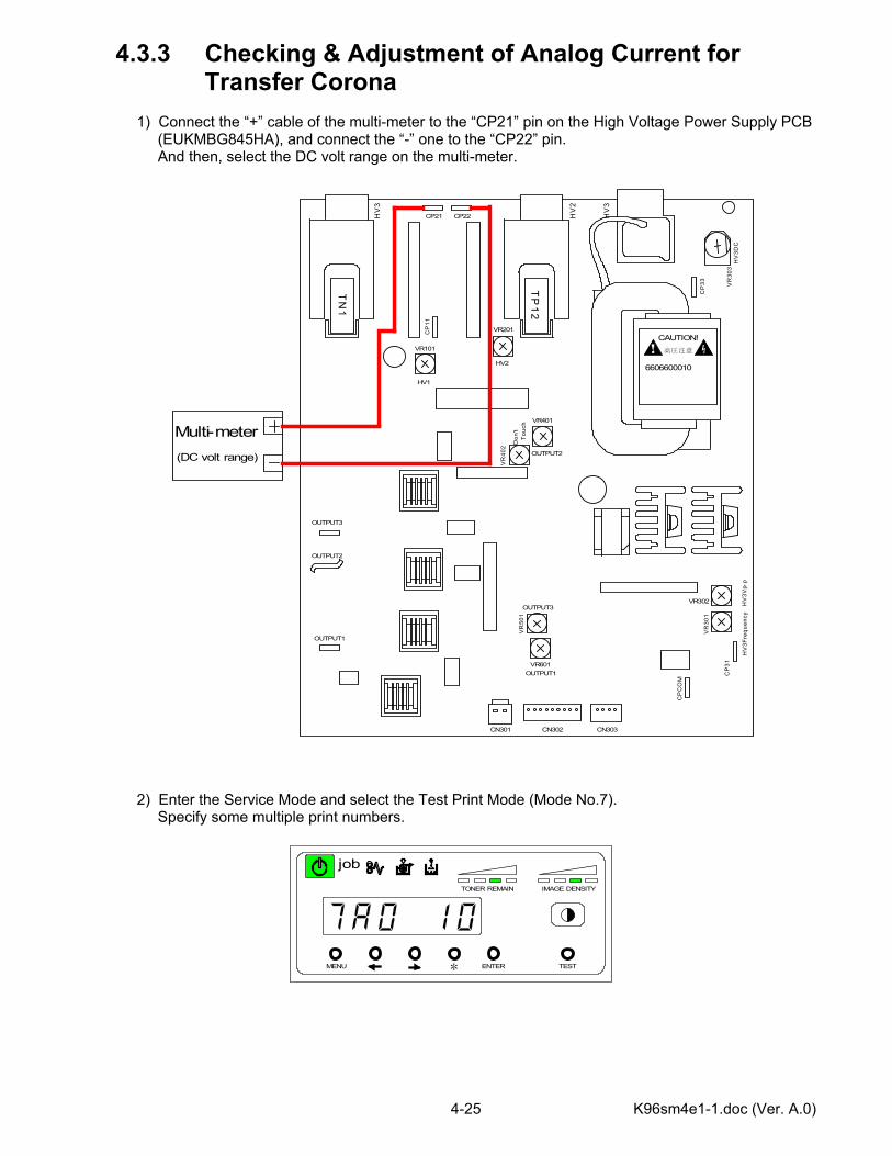
4.3.3 Checking & Adjustment of Analog Current for Transfer Corona 1) Connect the “+” cable of the multi-meter to the “CP21” pin on the High Voltage Power Supply PCB (EUKMBG845HA), and connect the “-” one to the “CP22” pin. And then, select the DC volt range on the multi-meter. 2) Enter the Service Mode and select the Test Print Mode (Mode No.7). Specify some multiple print numbers.
CAUTION!高圧注意
6606600010T
P1
2
TN
1
OUTPUT1
OUTPUT2
OUTPUT3
HV1
VR101
HV2
VR201
OUTPUT2
VR401
Don
'tTo
uch
VR
402
OUTPUT3
VR
501
OUTPUT1VR601
HV
3Vp-
p
VR302
VR
301
HV
3Fre
quen
cy
HV
3
HV
2
HV
3
HV
3DC
CN301 CN302 CN303C
P31
CP
CO
M
CP
33 VR
303
CP21 CP22
Multi-meterC
P11
(DC volt range)
MENU ENTER TEST
TONER REMAIN IMAGE DENSITY
job
*
K96sm4e1-1.doc (Ver. A.0) 4-26
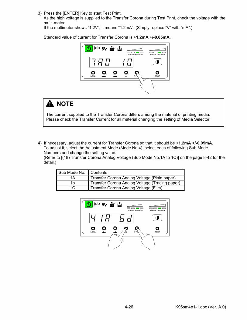
3) Press the [ENTER] Key to start Test Print. As the high voltage is supplied to the Transfer Corona during Test Print, check the voltage with the multi-meter. If the multimeter shows “1.2V”, it means “1.2mA”. (Simply replace “V” with “mA”.) Standard value of current for Transfer Corona is +1.2mA +/-0.05mA. 4) If necessary, adjust the current for Transfer Corona so that it should be +1.2mA +/-0.05mA. To adjust it, select the Adjustment Mode (Mode No.4), select each of following Sub Mode Numbers and change the setting value. (Refer to [(18) Transfer Corona Analog Voltage (Sub Mode No.1A to 1C)] on the page 8-42 for the detail.)
Sub Mode No. Contents 1A Transfer Corona Analog Voltage (Plain paper) 1b Transfer Corona Analog Voltage (Tracing paper) 1C Transfer Corona Analog Voltage (Film)
MENU ENTER TEST
TONER REMAIN IMAGE DENSITY
job
*
MENU ENTER TEST
TONER REMAIN IMAGE DENSITY
job
*
NOTE The current supplied to the Transfer Corona differs among the material of printing media. Please check the Transfer Current for all material changing the setting of Media Selector.
K96sm4e1-1.doc (Ver. A.0) 4-27
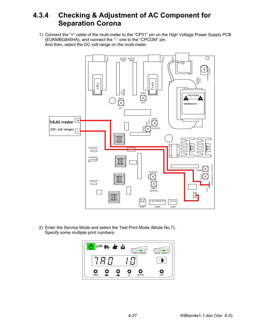
4.3.4 Checking & Adjustment of AC Component for Separation Corona 1) Connect the “+” cable of the multi-meter to the “CP31” pin on the High Voltage Power Supply PCB (EUKMBG845HA), and connect the “-” one to the “CPCOM” pin. And then, select the DC volt range on the multi-meter. 2) Enter the Service Mode and select the Test Print Mode (Mode No.7). Specify some multiple print numbers.
CAUTION!高圧注意
6606600010T
P1
2
TN
1
OUTPUT1
OUTPUT2
OUTPUT3
HV1
VR101
HV2
VR201
OUTPUT2
VR401
Don
'tTo
uch
VR
402
OUTPUT3
VR
501
OUTPUT1VR601
HV
3Vp-
p
VR302
VR
301
HV
3Fre
quen
cy
HV
3
HV
2
HV
3
HV
3DC
CN301 CN302 CN303C
P31
CP
CO
M
CP
33 VR
303
CP21 CP22
Multi-meterC
P11
(DC volt range)
MENU ENTER TEST
TONER REMAIN IMAGE DENSITY
job
*
K96sm4e1-1.doc (Ver. A.0) 4-28
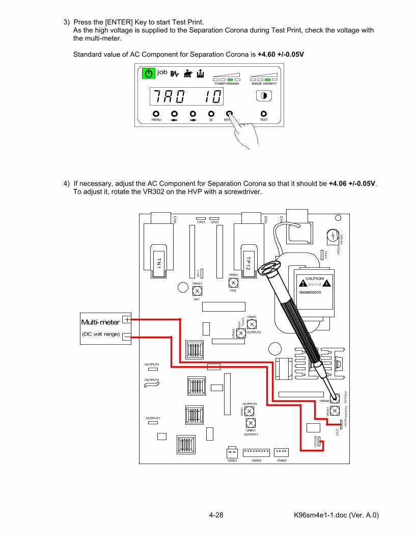
3) Press the [ENTER] Key to start Test Print. As the high voltage is supplied to the Separation Corona during Test Print, check the voltage with the multi-meter. Standard value of AC Component for Separation Corona is +4.60 +/-0.05V 4) If necessary, adjust the AC Component for Separation Corona so that it should be +4.06 +/-0.05V. To adjust it, rotate the VR302 on the HVP with a screwdriver.
CAUTION!高圧注意
6606600010
TP
12
TN
1
OUTPUT1
OUTPUT2
OUTPUT3
HV1
VR101
HV2
VR201
OUTPUT2
VR401
Don
'tTo
uch
VR
402
OUTPUT3
VR
501
OUTPUT1VR601
HV
3Vp-
p
VR302
VR
301
HV
3Fre
quen
cy
HV
3
HV
2
HV
3
HV
3DC
CN301 CN302 CN303
CP
31
CP
CO
M
CP
33 VR
303
CP21 CP22
Multi-meter
CP
11
(DC volt range)
MENU ENTER TEST
TONER REMAIN IMAGE DENSITY
job
*
K96sm4e1-1.doc (Ver. A.0) 4-29
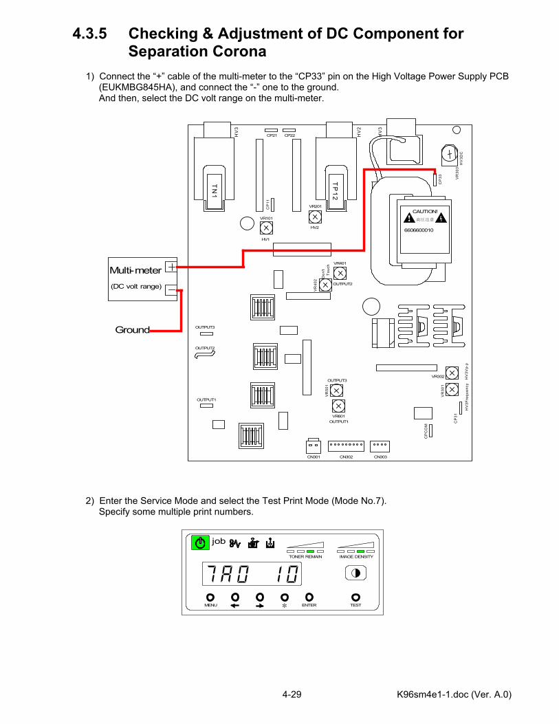
4.3.5 Checking & Adjustment of DC Component for Separation Corona 1) Connect the “+” cable of the multi-meter to the “CP33” pin on the High Voltage Power Supply PCB (EUKMBG845HA), and connect the “-” one to the ground. And then, select the DC volt range on the multi-meter. 2) Enter the Service Mode and select the Test Print Mode (Mode No.7). Specify some multiple print numbers.
CAUTION!高圧注意
6606600010T
P1
2
TN
1
OUTPUT1
OUTPUT2
OUTPUT3
HV1
VR101
HV2
VR201
OUTPUT2
VR401
Don
'tTo
uch
VR
402
OUTPUT3
VR
501
OUTPUT1VR601
HV
3Vp-
p
VR302
VR
301
HV
3Fre
quen
cy
HV
3
HV
2
HV
3
HV
3DC
CN301 CN302 CN303C
P31
CP
CO
M
CP
33 VR
303
CP21 CP22
Multi-meterC
P11
(DC volt range)
Ground
MENU ENTER TEST
TONER REMAIN IMAGE DENSITY
job
*
K96sm4e1-1.doc (Ver. A.0) 4-30
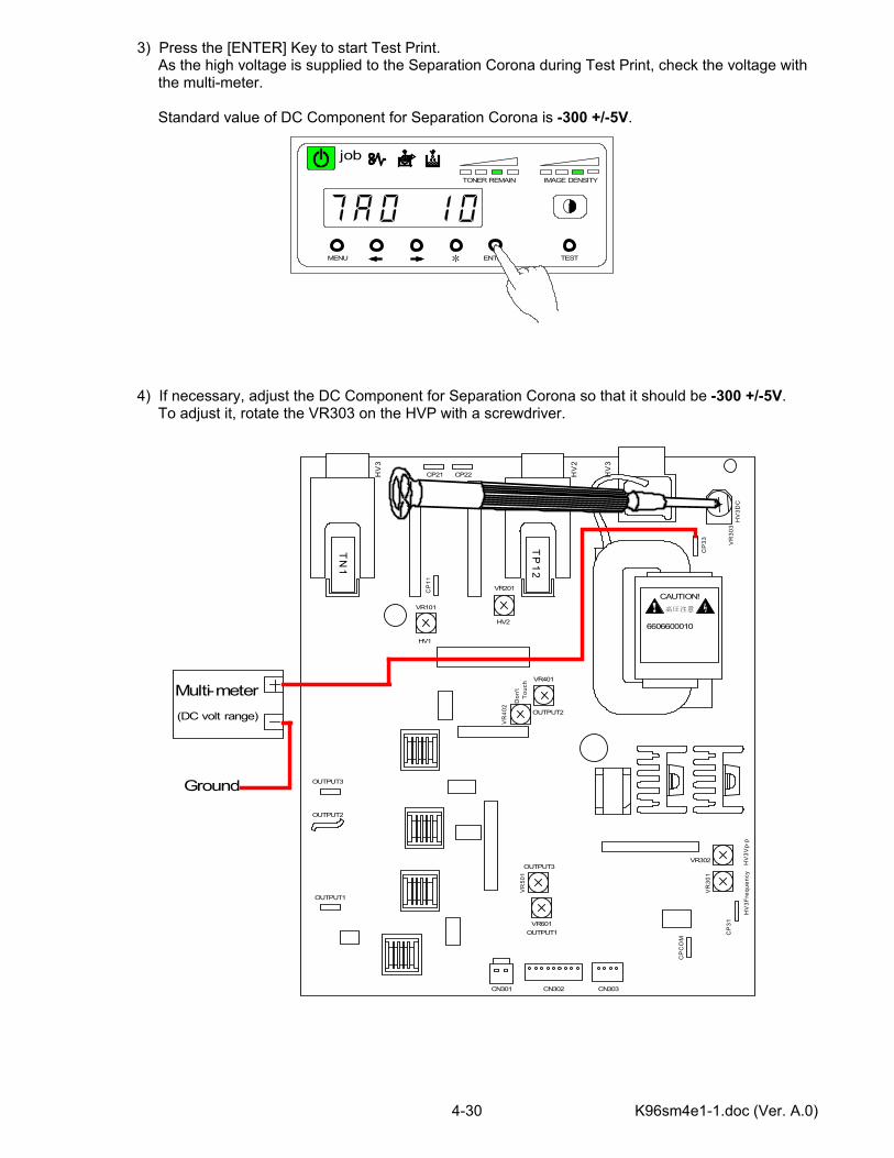
3) Press the [ENTER] Key to start Test Print. As the high voltage is supplied to the Separation Corona during Test Print, check the voltage with the multi-meter. Standard value of DC Component for Separation Corona is -300 +/-5V. 4) If necessary, adjust the DC Component for Separation Corona so that it should be -300 +/-5V. To adjust it, rotate the VR303 on the HVP with a screwdriver.
CAUTION!高圧注意
6606600010
TP
12
TN
1
OUTPUT1
OUTPUT2
OUTPUT3
HV1
VR101
HV2
VR201
OUTPUT2
VR401
Don
'tTo
uch
VR
402
OUTPUT3
VR
501
OUTPUT1VR601
HV
3Vp-
p
VR302
VR
301
HV
3Fre
quen
cy
HV
3
HV
2
HV
3
HV
3DC
CN301 CN302 CN303
CP
31
CP
CO
M
CP
33 VR
303
CP21 CP22
Multi-meter
CP
11
(DC volt range)
Ground
MENU ENTER TEST
TONER REMAIN IMAGE DENSITY
job
*

K96sm4e1-1.doc (Ver. A.0) 4-31
4.3.6 Checking & Adjustment of Negative Developer Bias for Development Roller 1) Connect the “+” cable of the multi-meter to the “OUTPUT2” pin on the High Voltage Power Supply PCB (EUKMBG845HA), and connect the “-” one to the ground. And then, select the DC volt range on the multi-meter. 2) Enter the Service Mode and select the Test Print Mode (Mode No.7). Specify some multiple print numbers.
CAUTION!高圧注意
6606600010T
P1
2
TN
1
OUTPUT1
OUTPUT2
OUTPUT3
HV1
VR101
HV2
VR201
OUTPUT2
VR401
Don
'tTo
uch
VR
402
OUTPUT3
VR
501
OUTPUT1VR601
HV
3Vp-
p
VR302
VR
301
HV
3Fre
quen
cy
HV
3
HV
2
HV
3
HV
3DC
CN301 CN302 CN303C
P31
CP
CO
M
CP
33 VR
303
CP21 CP22
Multi-meterC
P11
(DC volt range)
Ground
MENU ENTER TEST
TONER REMAIN IMAGE DENSITY
job
*
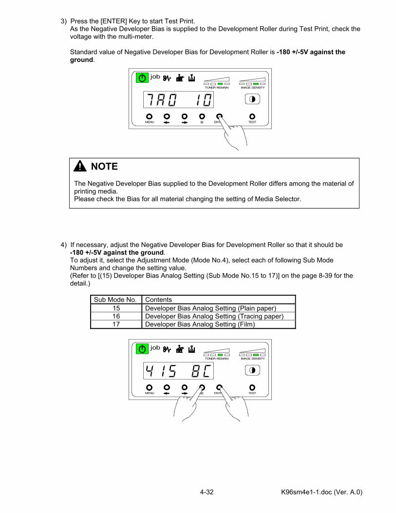
K96sm4e1-1.doc (Ver. A.0) 4-32
3) Press the [ENTER] Key to start Test Print. As the Negative Developer Bias is supplied to the Development Roller during Test Print, check the voltage with the multi-meter. Standard value of Negative Developer Bias for Development Roller is -180 +/-5V against the ground. 4) If necessary, adjust the Negative Developer Bias for Development Roller so that it should be -180 +/-5V against the ground. To adjust it, select the Adjustment Mode (Mode No.4), select each of following Sub Mode Numbers and change the setting value. (Refer to [(15) Developer Bias Analog Setting (Sub Mode No.15 to 17)] on the page 8-39 for the detail.)
Sub Mode No. Contents 15 Developer Bias Analog Setting (Plain paper) 16 Developer Bias Analog Setting (Tracing paper) 17 Developer Bias Analog Setting (Film)
MENU ENTER TEST
TONER REMAIN IMAGE DENSITY
job
*
MENU ENTER TEST
TONER REMAIN IMAGE DENSITY
job
*
NOTE The Negative Developer Bias supplied to the Development Roller differs among the material of printing media. Please check the Bias for all material changing the setting of Media Selector.
K96sm4e1-1.doc (Ver. A.0) 4-33
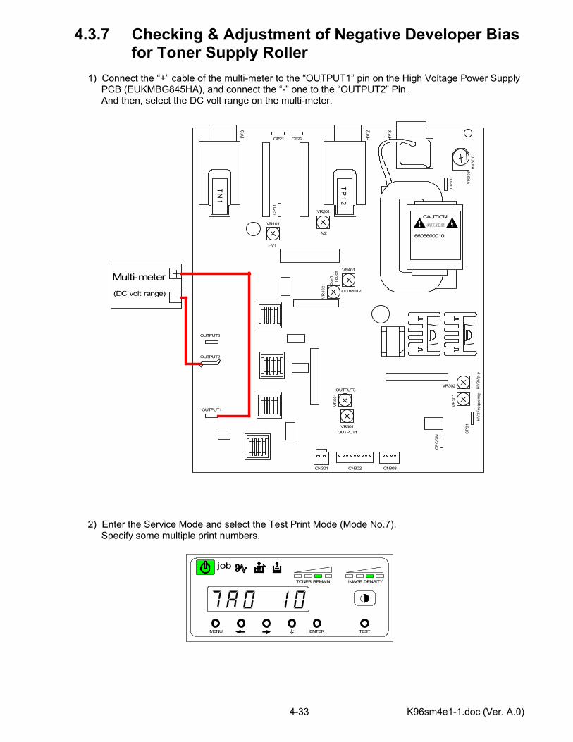
4.3.7 Checking & Adjustment of Negative Developer Bias for Toner Supply Roller 1) Connect the “+” cable of the multi-meter to the “OUTPUT1” pin on the High Voltage Power Supply PCB (EUKMBG845HA), and connect the “-” one to the “OUTPUT2” Pin. And then, select the DC volt range on the multi-meter. 2) Enter the Service Mode and select the Test Print Mode (Mode No.7). Specify some multiple print numbers.
CAUTION!高圧注意
6606600010T
P1
2
TN
1
OUTPUT1
OUTPUT2
OUTPUT3
HV1
VR101
HV2
VR201
OUTPUT2
VR401
Don
'tTo
uch
VR
402
OUTPUT3
VR
501
OUTPUT1VR601
HV
3Vp-
p
VR302
VR
301
HV
3Fre
quen
cy
HV
3
HV
2
HV
3
HV
3DC
CN301 CN302 CN303C
P31
CP
CO
M
CP
33 VR
303
CP21 CP22
Multi-meterC
P11
(DC volt range)
MENU ENTER TEST
TONER REMAIN IMAGE DENSITY
job
*
K96sm4e1-1.doc (Ver. A.0) 4-34
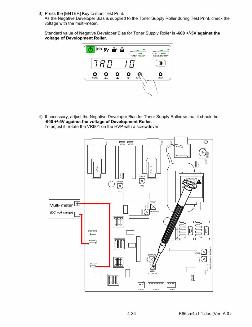
3) Press the [ENTER] Key to start Test Print. As the Negative Developer Bias is supplied to the Toner Supply Roller during Test Print, check the voltage with the multi-meter. Standard value of Negative Developer Bias for Toner Supply Roller is -600 +/-5V against the voltage of Development Roller. 4) If necessary, adjust the Negative Developer Bias for Toner Supply Roller so that it should be -600 +/-5V against the voltage of Development Roller. To adjust it, rotate the VR601 on the HVP with a screwdriver.
CAUTION!高圧注意
6606600010
TP
12
TN
1
OUTPUT1
OUTPUT2
OUTPUT3
HV1
VR101
HV2
VR201
OUTPUT2
VR401
Don
'tTo
uch
VR
402
OUTPUT3
VR
501
OUTPUT1VR601
HV
3Vp-
p
VR302
VR
301
HV
3Fre
quen
cy
HV
3
HV
2
HV
3
HV
3DC
CN301 CN302 CN303
CP
31
CP
CO
M
CP
33 VR
303
CP21 CP22
Multi-meter
CP
11
(DC volt range)
MENU ENTER TEST
TONER REMAIN IMAGE DENSITY
job
*
K96sm4e1-1.doc (Ver. A.0) 4-35
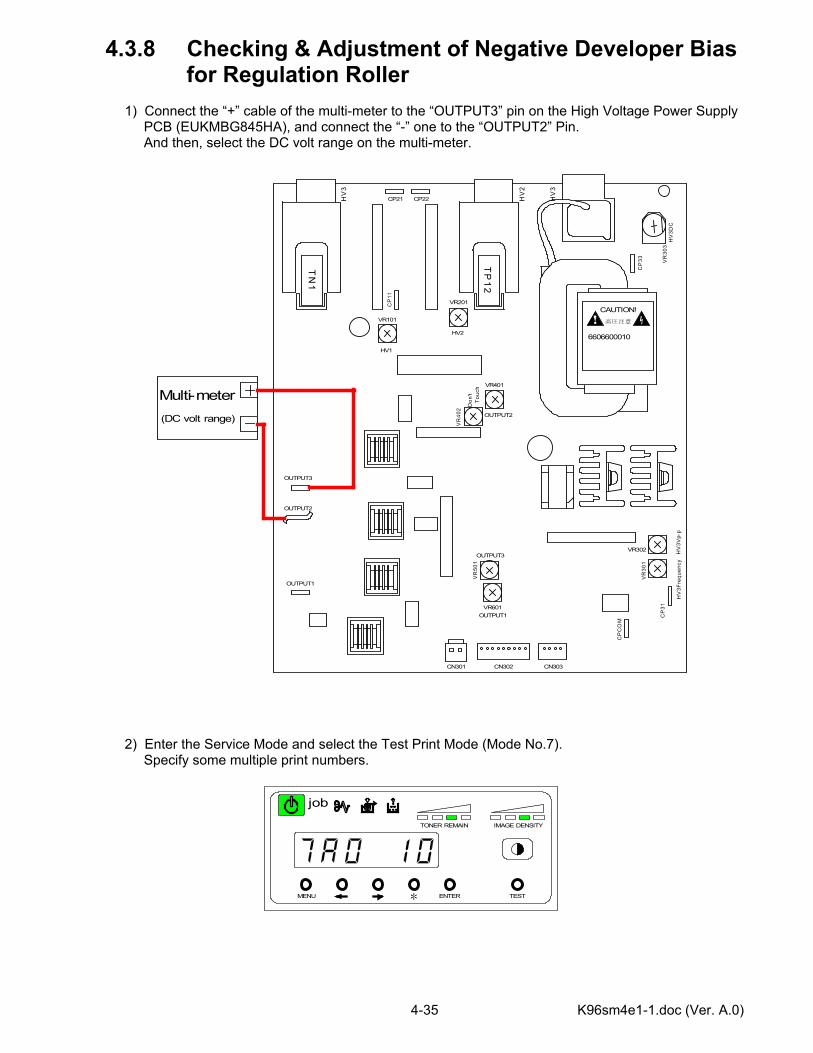
4.3.8 Checking & Adjustment of Negative Developer Bias for Regulation Roller 1) Connect the “+” cable of the multi-meter to the “OUTPUT3” pin on the High Voltage Power Supply PCB (EUKMBG845HA), and connect the “-” one to the “OUTPUT2” Pin. And then, select the DC volt range on the multi-meter. 2) Enter the Service Mode and select the Test Print Mode (Mode No.7). Specify some multiple print numbers.
CAUTION!高圧注意
6606600010T
P1
2
TN
1
OUTPUT1
OUTPUT2
OUTPUT3
HV1
VR101
HV2
VR201
OUTPUT2
VR401
Don
'tTo
uch
VR
402
OUTPUT3
VR
501
OUTPUT1VR601
HV
3Vp-
p
VR302
VR
301
HV
3Fre
quen
cy
HV
3
HV
2
HV
3
HV
3DC
CN301 CN302 CN303C
P31
CP
CO
M
CP
33 VR
303
CP21 CP22
Multi-meterC
P11
(DC volt range)
MENU ENTER TEST
TONER REMAIN IMAGE DENSITY
job
*
K96sm4e1-1.doc (Ver. A.0) 4-36
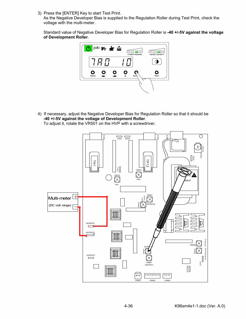
3) Press the [ENTER] Key to start Test Print. As the Negative Developer Bias is supplied to the Regulation Roller during Test Print, check the voltage with the multi-meter. Standard value of Negative Developer Bias for Regulation Roller is -40 +/-5V against the voltage of Development Roller. 4) If necessary, adjust the Negative Developer Bias for Regulation Roller so that it should be -40 +/-5V against the voltage of Development Roller. To adjust it, rotate the VR501 on the HVP with a screwdriver.
CAUTION!高圧注意
6606600010
TP
12
TN
1
OUTPUT1
OUTPUT2
OUTPUT3
HV1
VR101
HV2
VR201
OUTPUT2
VR401
Don
'tTo
uch
VR
402
OUTPUT3
VR
501
OUTPUT1VR601
HV
3Vp-
p
VR302
VR
301
HV
3Fre
quen
cy
HV
3
HV
2
HV
3
HV
3DC
CN301 CN302 CN303
CP
31
CP
CO
M
CP
33 VR
303
CP21 CP22
Multi-meter
CP
11
(DC volt range)
MENU ENTER TEST
TONER REMAIN IMAGE DENSITY
job
*

K96sm4e1-1.doc (Ver. A.0) 4-37
4.3.9 Checking & Adjustment of Positive Developer Bias for Development Roller 1) Connect the “+” cable of the multi-meter to the “OUTPUT2” pin on the High Voltage Power Supply PCB (EUKMBG845HA), and connect the “-” one to the ground. And then, select the DC volt range on the multi-meter. 2) Enter the Service Mode and select the Test Print Mode (Mode No.7). Specify “1 sheet” as the print number.
CAUTION!高圧注意
6606600010T
P1
2
TN
1
OUTPUT1
OUTPUT2
OUTPUT3
HV1
VR101
HV2
VR201
OUTPUT2
VR401
Don
'tTo
uch
VR
402
OUTPUT3
VR
501
OUTPUT1VR601
HV
3Vp-
p
VR302
VR
301
HV
3Fre
quen
cy
HV
3
HV
2
HV
3
HV
3DC
CN301 CN302 CN303C
P31
CP
CO
M
CP
33 VR
303
CP21 CP22
Multi-meterC
P11
(DC volt range)
Ground
MENU ENTER TEST
TONER REMAIN IMAGE DENSITY
job
*

K96sm4e1-1.doc (Ver. A.0) 4-38
3) Press the [ENTER] Key to start Test Print, and then wait until it is finished. As the Positive Developer Bias is supplied to the Regulation Roller when the printer is going to stop, check the voltage with the multi-meter. Standard value of Positive Developer Bias for Development Roller is +350 +/-5V against the ground. 4) If necessary, adjust the Positive Developer Bias for Development Roller so that it should be +350 +/-5V against the ground. To adjust it, rotate the VR401 on the HVP with a screwdriver.
CAUTION!高圧注意
6606600010
TP
12
TN
1
OUTPUT1
OUTPUT2
OUTPUT3
HV1
VR101
HV2
VR201
OUTPUT2
VR401
Don
'tTo
uch
VR
402
OUTPUT3
VR
501
OUTPUT1VR601
HV
3Vp-
p
VR302
VR
301
HV
3Fre
quen
cy
HV
3
HV
2
HV
3
HV
3DC
CN301 CN302 CN303
CP
31
CP
CO
M
CP
33 VR
303
CP21 CP22
Multi-meter
CP
11
(DC volt range)
Ground
MENU ENTER TEST
TONER REMAIN IMAGE DENSITY
job
*
K96sm4e1-1.doc (Ver. A.0) 4-39
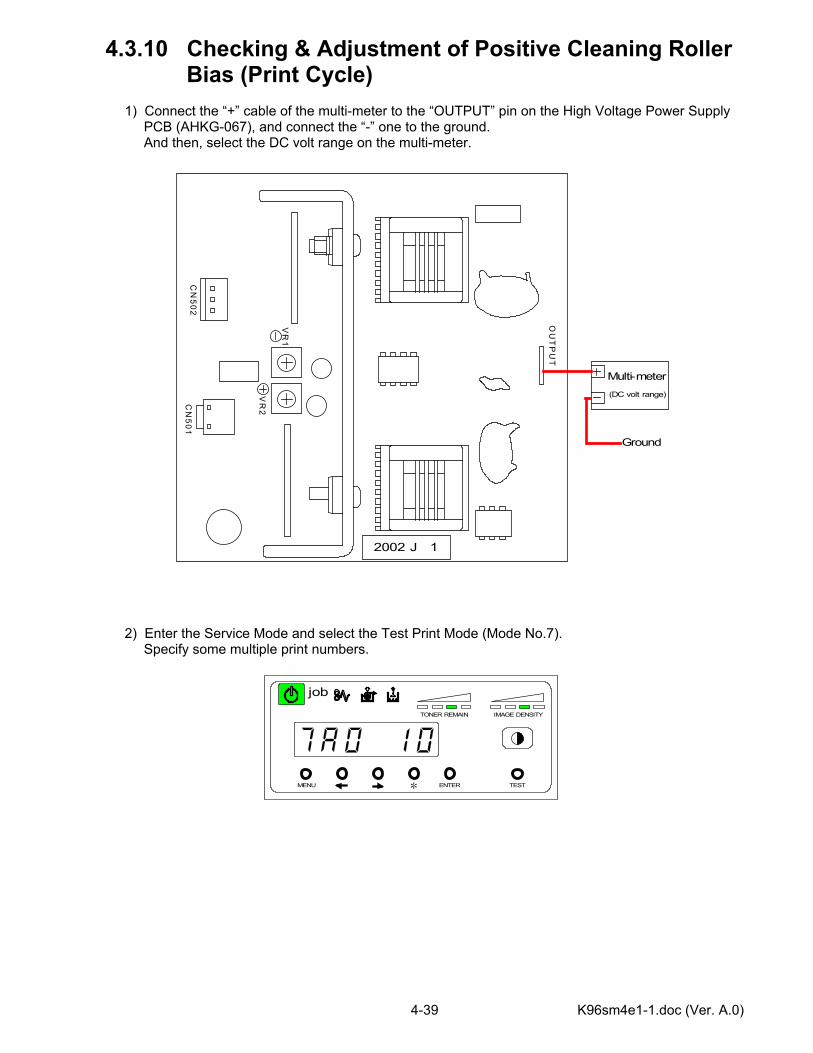
4.3.10 Checking & Adjustment of Positive Cleaning Roller Bias (Print Cycle) 1) Connect the “+” cable of the multi-meter to the “OUTPUT” pin on the High Voltage Power Supply PCB (AHKG-067), and connect the “-” one to the ground. And then, select the DC volt range on the multi-meter. 2) Enter the Service Mode and select the Test Print Mode (Mode No.7). Specify some multiple print numbers.
2002 J 1
OU
TP
UT
CN
501C
N502
Multi-meter(DC volt range)
Ground
VR
1
VR
2
MENU ENTER TEST
TONER REMAIN IMAGE DENSITY
job
*
K96sm4e1-1.doc (Ver. A.0) 4-40
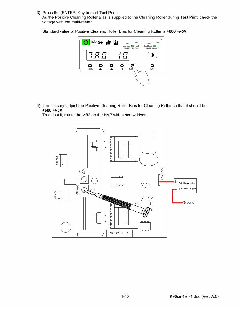
3) Press the [ENTER] Key to start Test Print. As the Positive Cleaning Roller Bias is supplied to the Cleaning Roller during Test Print, check the voltage with the multi-meter. Standard value of Positive Cleaning Roller Bias for Cleaning Roller is +600 +/-5V. 4) If necessary, adjust the Positive Cleaning Roller Bias for Cleaning Roller so that it should be +600 +/-5V. To adjust it, rotate the VR2 on the HVP with a screwdriver.
2002 J 1
OU
TP
UT
CN
501C
N502
Multi-meter(DC volt range)
Ground
VR
1
VR
2
MENU ENTER TEST
TONER REMAIN IMAGE DENSITY
job
*
K96sm4e1-1.doc (Ver. A.0) 4-41
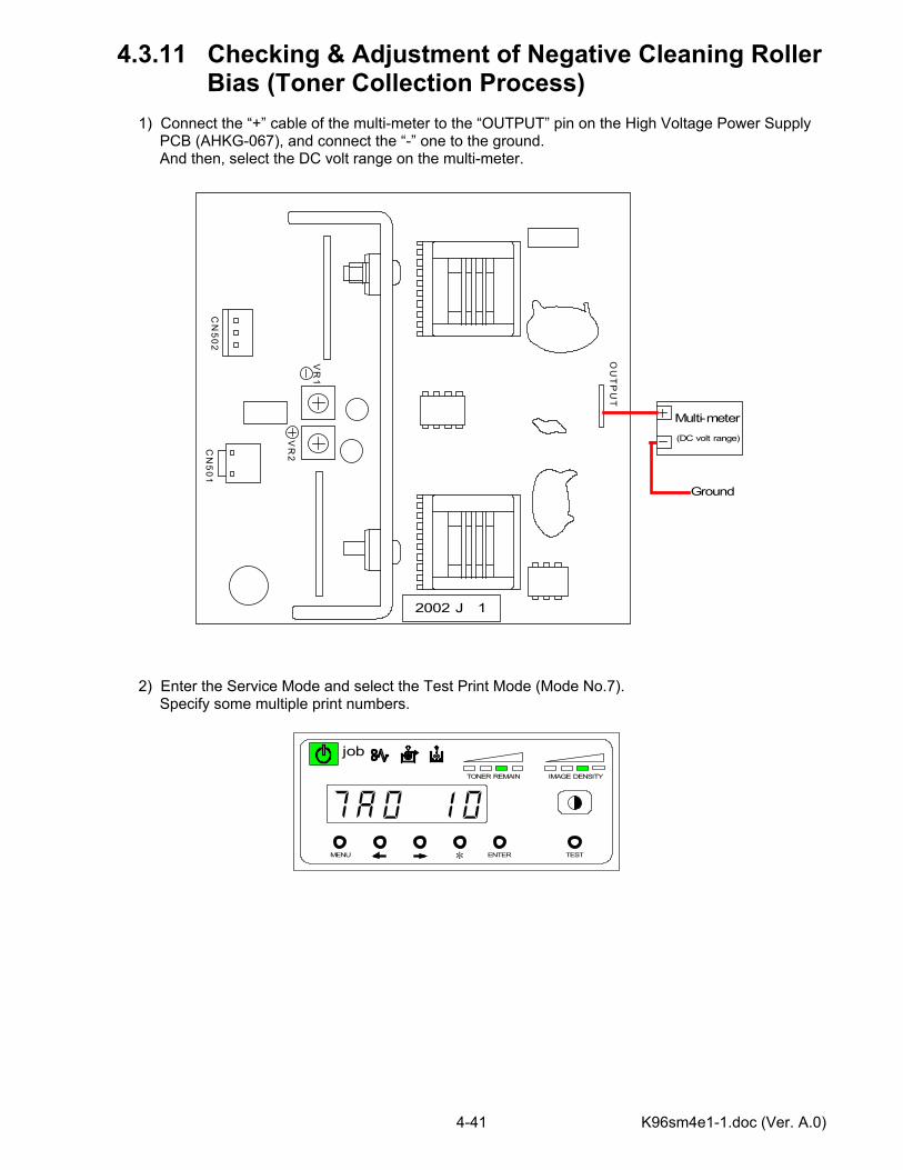
4.3.11 Checking & Adjustment of Negative Cleaning Roller Bias (Toner Collection Process) 1) Connect the “+” cable of the multi-meter to the “OUTPUT” pin on the High Voltage Power Supply PCB (AHKG-067), and connect the “-” one to the ground. And then, select the DC volt range on the multi-meter. 2) Enter the Service Mode and select the Test Print Mode (Mode No.7). Specify some multiple print numbers.
2002 J 1
OU
TP
UT
CN
501C
N502
Multi-meter(DC volt range)
Ground
VR
1
VR
2
MENU ENTER TEST
TONER REMAIN IMAGE DENSITY
job
*
K96sm4e1-1.doc (Ver. A.0) 4-42
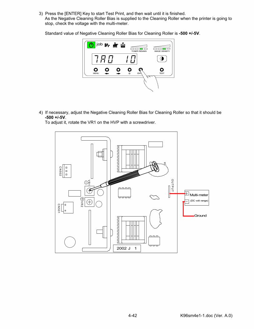
3) Press the [ENTER] Key to start Test Print, and then wait until it is finished. As the Negative Cleaning Roller Bias is supplied to the Cleaning Roller when the printer is going to stop, check the voltage with the multi-meter. Standard value of Negative Cleaning Roller Bias for Cleaning Roller is -500 +/-5V. 4) If necessary, adjust the Negative Cleaning Roller Bias for Cleaning Roller so that it should be -500 +/-5V. To adjust it, rotate the VR1 on the HVP with a screwdriver.
2002 J 1
OU
TP
UT
CN
501C
N502
Multi-meter(DC volt range)
Ground
VR
1
VR
2
MENU ENTER TEST
TONER REMAIN IMAGE DENSITY
job
*
K96sm5e1.doc (Ver. A.0) (1)
Chapter 5
Mechanical Systems Page 5.1 External covers 5- 2 5.1.1 Toner Cover 5- 3 5.1.2 Top Cover 5- 5 5.1.3 Right/Left Covers 5- 7 5.1.4 Right/Left Front Covers 5- 8 5.1.5 Right/Left Rear Covers 5-10 5.1.6 Exit Cover 5-11 5.1.7 Rear Cover 5-11 5.2 Process Unit 5-12 5.2.1 Opening of Movable Unit 5-12 5.2.2 Disassembling Process Unit 5-14 5.2.3 Photoconductive drum 5-15 5.2.4 LED Head 5-17 5.2.5 Eraser Lamp 5-18 5.2.6 LED Head Cooling Fans (Fan3A, Fan3B) 5-19 5.2.7 Pre-Transfer LED 5-19 5.2.8 Main motor (M1) 5-20 5.2.9 Timing belts (two) 5-21 A. Timing belt for main motor 5-21 B. Timing belt for Pulley/P161 5-21 5.3 Main frame 5-22 5.3.1 Paper gate clutch (MC3) 5-22 5.3.2 Timing belt 5-23 A. Timing belt for Inside feed assembly 5-23 5.3.3 Ozone filters 5-24 5.3.4 Fans 5-25 A. Fuser Cooling Fan Left/Right (Fan 1A, Fan 1B) 5-25 5.3.5 Counter (CNT1) 5-26 5.3.6 Main switch (S1) 5-26 5.3.7 Cutter Assembly 5-27 A. Paper sensor below Cutter (PH3) 5-29 5.4 Primary Charger Assembly 5-30 5.4.1 Primary Charger Assembly 5-30 5.4.2 Corona Charging Wire 5-31 5.4.3 Height adjustment of corona charging wire 5-32 5.4.4 Grid plate 5-32 5.4.5 Wire cleaning motor (M4) 5-33 5.4.6 Wire cleaning pad 5-34
K96sm5e1.doc (Ver. A.0) (2)
5.5 Transfer/Separation charger assembly 5-35 5.5.1 Transfer/Separation charger assembly 5-35 5.5.2 Transfer/Separation corona charging wire 5-36 5.5.3 Corona Guard 5-36 5.5.4 Height adjustment of corona charging wire 5-37 5.6 Fuser Unit 5-38 5.6.1 Disassembling Fuser Unit 5-38 5.6.2 Fuser Lamp 5-39 5.6.3 Thermistors (TH1, TH2) 5-40 5.6.4 Thermostats (TS1A, TS1B) 5-40 5.6.5 Fuser Roller 5-41 5.6.6 Pressure Roller 5-44 5.6.7 Paper Exit Sensor (PH8) 5-45 5.6.8 Thermistor (TH3) 5-45 5.6.9 Exit Roller 5-46 5.7 Development Unit 5-47 5.7.1 Removing Toner Hopper 5-47 5.7.2 Development Roller 5-49 5.7.3 Regulation Roller 5-52 5.7.4 Supply Roller and Side Seals 5-54 5.7.5 Sender Screw 5-56 5.7.6 Scraper 5-57 5.7.7 Toner Motor (M6) 5-59 5.7.8 Toner Sensors (TLS1, TLS2) 5-59 5.7.9 Spacing Roller 5-60 A. Left side 5-60 B. Right side 5-60 5.7.10 Gears 5-61 5.8 Internal Feeder Unit 5-62 5.8.1 Disassembling Internal Feeder Unit 5-62 5.8.2 Paper separation sensor (PH7) 5-64 5.8.3 Feed belt 5-65 5.8.4 Feed roller 5-65 5.8.5 Separation fan (Fan 2) 5-66 5.9 Paper feeder assembly 5-67 5.9.1 Roll decks 5-68 5.9.2 Roll feed motor (M2) 5-69 5.9.3 Roll Feed Clutches (MC1, MC1B, MC1C, MC1D) 5-70 5.9.4 Pick up Roller (Roll 1, Roll 3) 5-71 5.9.5 Pick up Roller (Roll 2, Roll 4) 5-72 5.9.6 Sensors 5-74 A. Paper end clock sensors (PH2A, PH2B, PH2C, PH2D) 5-74 B. Paper set sensors (PH1A, PH1B, PH1C, PH1D) 5-75 5.9.6 Size switch 5-73 5.9.7 Fitting Paper feeder assembly (Option) 5-74 5.10 Cassette Assembly (Option) 5-78 5.10.1 Removing Bottom Deck 5-79 5.10.2 Install the Cassette Case 5-80 5.10.3 Install the Cassette 5-82 5.10.4 Service Mode Setting 5-83
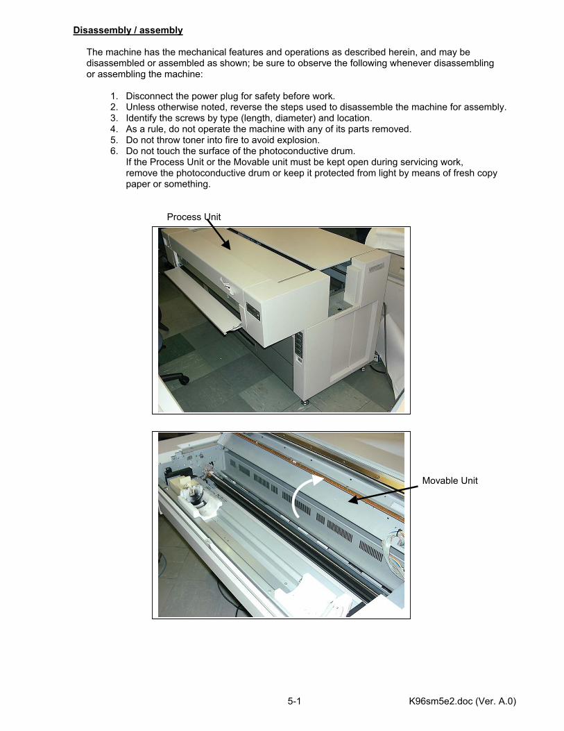
K96sm5e2.doc (Ver. A.0) 5-1
Disassembly / assembly The machine has the mechanical features and operations as described herein, and may be disassembled or assembled as shown; be sure to observe the following whenever disassembling or assembling the machine:
1. Disconnect the power plug for safety before work. 2. Unless otherwise noted, reverse the steps used to disassemble the machine for assembly. 3. Identify the screws by type (length, diameter) and location. 4. As a rule, do not operate the machine with any of its parts removed. 5. Do not throw toner into fire to avoid explosion. 6. Do not touch the surface of the photoconductive drum.
If the Process Unit or the Movable unit must be kept open during servicing work, remove the photoconductive drum or keep it protected from light by means of fresh copy paper or something.
Process Unit Movable Unit
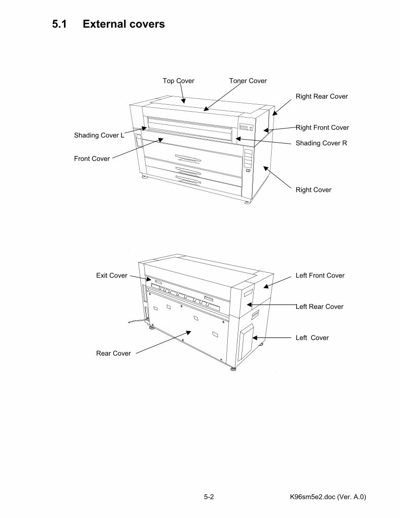
K96sm5e2.doc (Ver. A.0) 5-2
5.1 External covers Top Cover Toner Cover Right Rear Cover Right Front Cover Shading Cover L Shading Cover R Front Cover Right Cover Exit Cover Left Front Cover
Left Rear Cover Left Cover Rear Cover

K96sm5e2.doc (Ver. A.0) 5-3
5.1.1 Toner Cover 1) Open the Manual Table. 2) Open the Toner Cover. 3) Loosen screws (A), and then move Shaft Brackets on both sides toward the arrow direction. Also, loosen 2 screws (B) on either side (ex. Left).
A
B
A
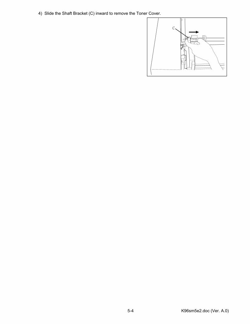
K96sm5e2.doc (Ver. A.0) 5-4
4) Slide the Shaft Bracket (C) inward to remove the Toner Cover.
C
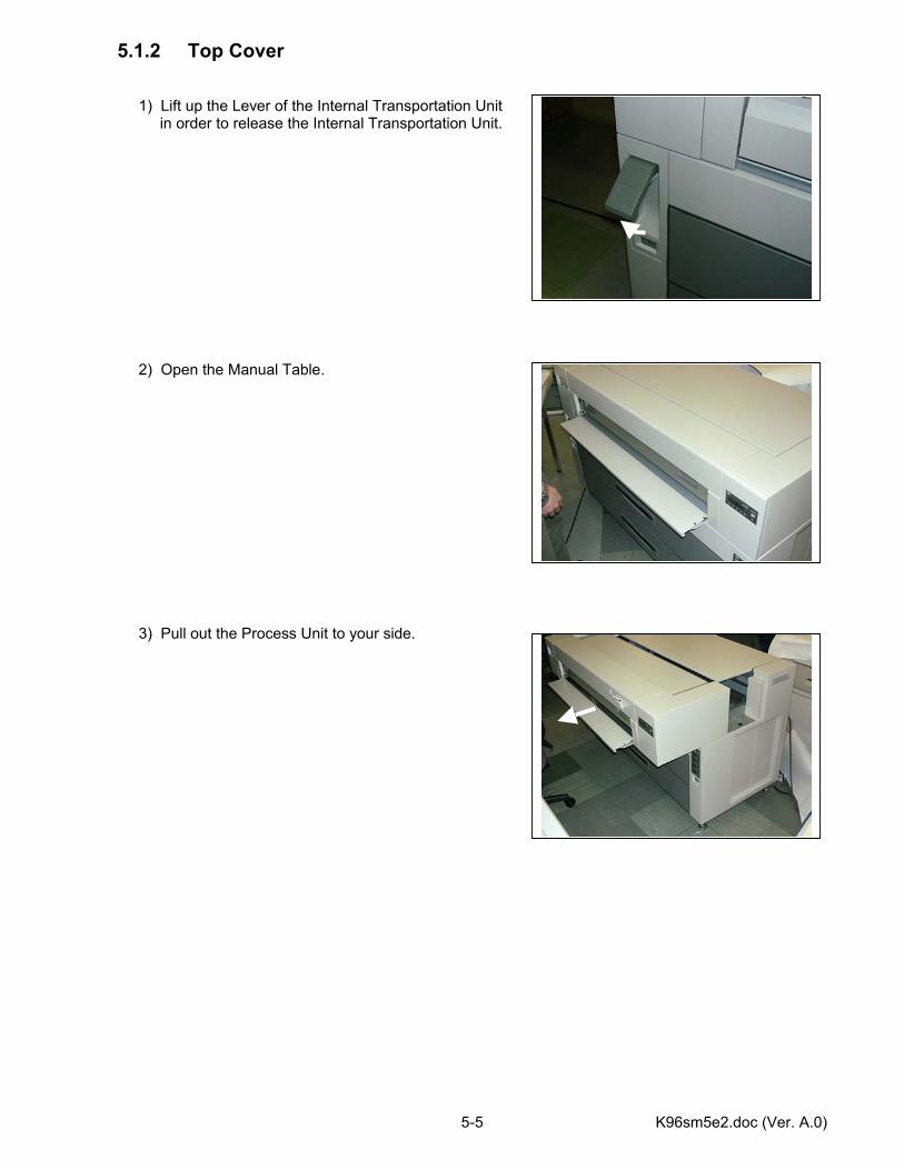
K96sm5e2.doc (Ver. A.0) 5-5
5.1.2 Top Cover 1) Lift up the Lever of the Internal Transportation Unit in order to release the Internal Transportation Unit. 2) Open the Manual Table. 3) Pull out the Process Unit to your side.
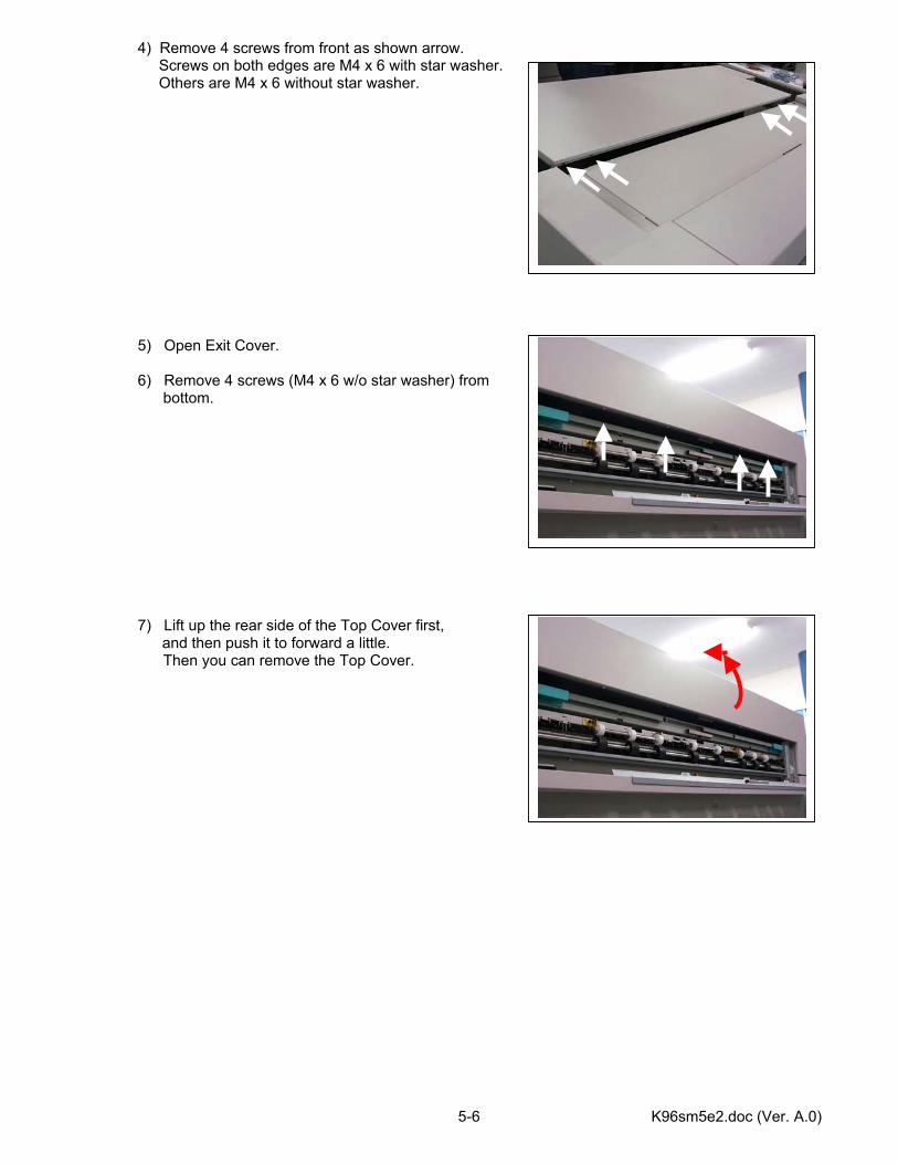
K96sm5e2.doc (Ver. A.0) 5-6
4) Remove 4 screws from front as shown arrow. Screws on both edges are M4 x 6 with star washer. Others are M4 x 6 without star washer. 5) Open Exit Cover. 6) Remove 4 screws (M4 x 6 w/o star washer) from bottom. 7) Lift up the rear side of the Top Cover first,
and then push it to forward a little. Then you can remove the Top Cover.
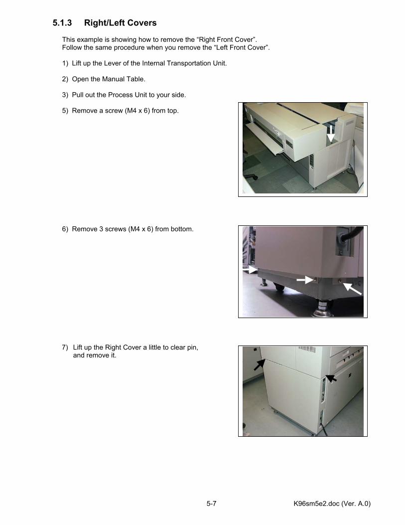
K96sm5e2.doc (Ver. A.0) 5-7
5.1.3 Right/Left Covers This example is showing how to remove the “Right Front Cover”. Follow the same procedure when you remove the “Left Front Cover”. 1) Lift up the Lever of the Internal Transportation Unit. 2) Open the Manual Table. 3) Pull out the Process Unit to your side. 5) Remove a screw (M4 x 6) from top. 6) Remove 3 screws (M4 x 6) from bottom.
7) Lift up the Right Cover a little to clear pin, and remove it.
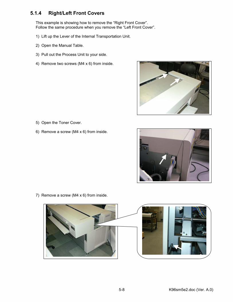
K96sm5e2.doc (Ver. A.0) 5-8
5.1.4 Right/Left Front Covers This example is showing how to remove the “Right Front Cover”. Follow the same procedure when you remove the “Left Front Cover”. 1) Lift up the Lever of the Internal Transportation Unit. 2) Open the Manual Table. 3) Pull out the Process Unit to your side. 4) Remove two screws (M4 x 6) from inside. 5) Open the Toner Cover. 6) Remove a screw (M4 x 6) from inside. 7) Remove a screw (M4 x 6) from inside.
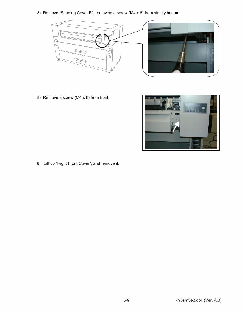
K96sm5e2.doc (Ver. A.0) 5-9
8) Remove “Shading Cover R”, removing a screw (M4 x 6) from slantly bottom. 8) Remove a screw (M4 x 6) from front.
8) Lift up “Right Front Cover”, and remove it.
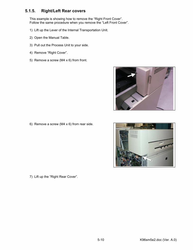
K96sm5e2.doc (Ver. A.0) 5-10
5.1.5. Right/Left Rear covers This example is showing how to remove the “Right Front Cover”. Follow the same procedure when you remove the “Left Front Cover”. 1) Lift up the Lever of the Internal Transportation Unit. 2) Open the Manual Table. 3) Pull out the Process Unit to your side. 4) Remove “Right Cover”. 5) Remove a screw (M4 x 6) from front. 6) Remove a screw (M4 x 6) from rear side. 7) Lift up the “Right Rear Cover”.
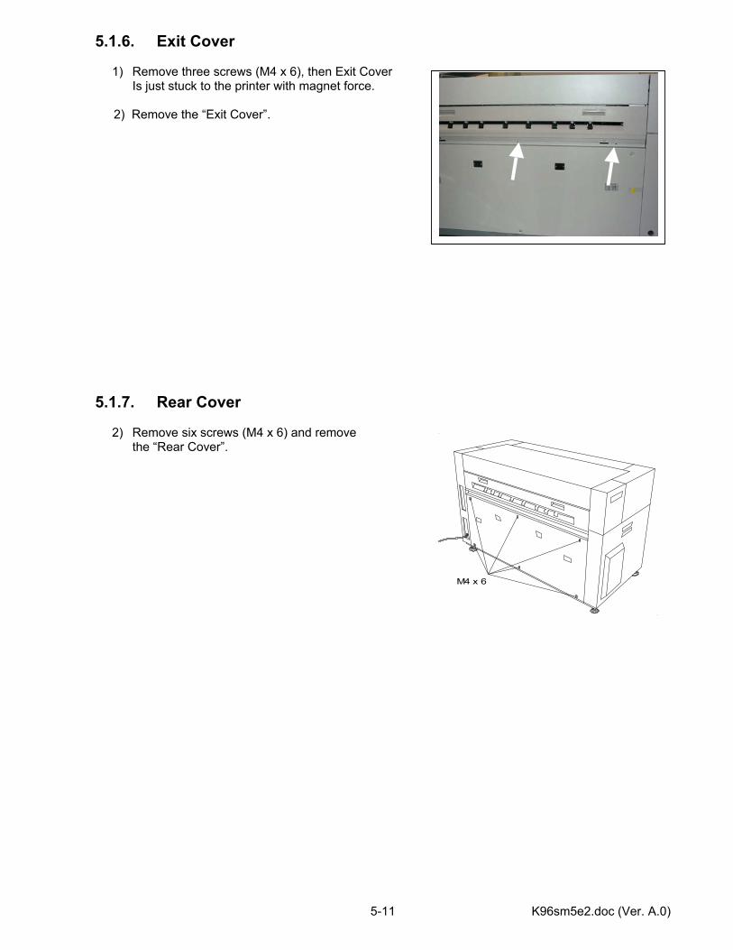
K96sm5e2.doc (Ver. A.0) 5-11
5.1.6. Exit Cover
1) Remove three screws (M4 x 6), then Exit Cover Is just stuck to the printer with magnet force.
2) Remove the “Exit Cover”.
5.1.7. Rear Cover
2) Remove six screws (M4 x 6) and remove the “Rear Cover”.
M4 x 6
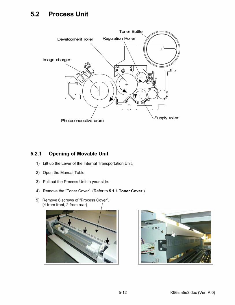
K96sm5e3.doc (Ver. A.0) 5-12
5.2 Process Unit 5.2.1 Opening of Movable Unit 1) Lift up the Lever of the Internal Transportation Unit. 2) Open the Manual Table. 3) Pull out the Process Unit to your side. 4) Remove the “Toner Cover”. (Refer to 5.1.1 Toner Cover.)
5) Remove 6 screws of “Process Cover”. (4 from front, 2 from rear)
Supply rollerPhotoconductive drum
Development roller
Image charger
Regulation Roller
Toner Bottle
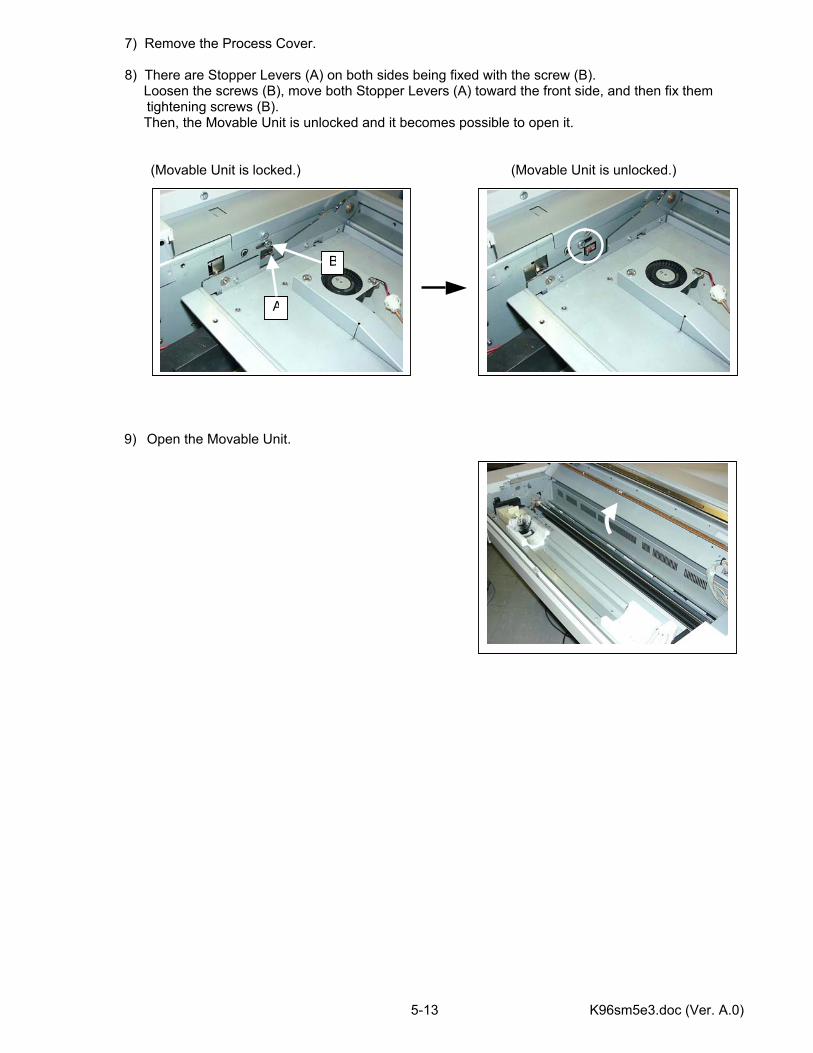
K96sm5e3.doc (Ver. A.0) 5-13
7) Remove the Process Cover. 8) There are Stopper Levers (A) on both sides being fixed with the screw (B). Loosen the screws (B), move both Stopper Levers (A) toward the front side, and then fix them
tightening screws (B). Then, the Movable Unit is unlocked and it becomes possible to open it. (Movable Unit is locked.) (Movable Unit is unlocked.)
9) Open the Movable Unit.
A
B
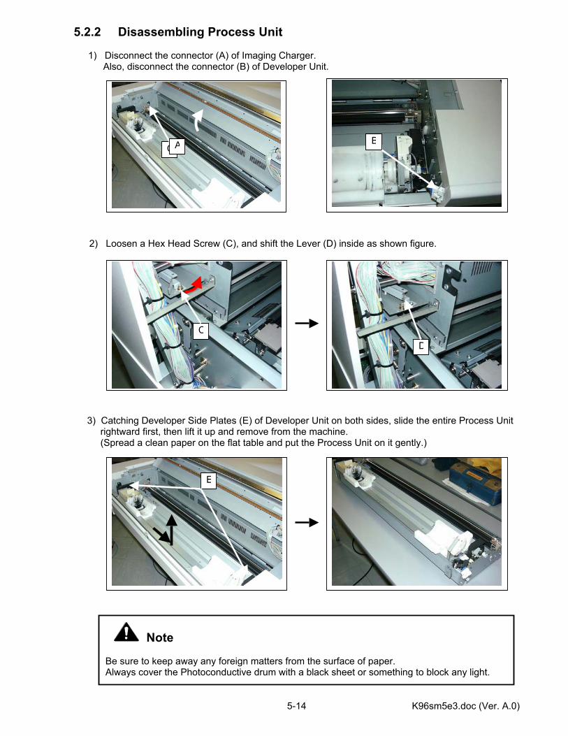
K96sm5e3.doc (Ver. A.0) 5-14
5.2.2 Disassembling Process Unit
1) Disconnect the connector (A) of Imaging Charger. Also, disconnect the connector (B) of Developer Unit. 2) Loosen a Hex Head Screw (C), and shift the Lever (D) inside as shown figure.
3) Catching Developer Side Plates (E) of Developer Unit on both sides, slide the entire Process Unit
rightward first, then lift it up and remove from the machine. (Spread a clean paper on the flat table and put the Process Unit on it gently.)
Note Be sure to keep away any foreign matters from the surface of paper. Always cover the Photoconductive drum with a black sheet or something to block any light.
CB
D
E
C
A

K96sm5e3.doc (Ver. A.0) 5-15
5.2.3 Photoconductive Drum 1) Take out the Process Unit following the “5.2.1 Opening of Movable Unit” and “5.2.2
Disassembling Process Unit”. 2) Take out the Primary charger assembly (1). See “5.6.1 Primary charger assembly”. 3) Remove the Pole holder (2) from the left side plate. (three screws, lower one is a flat head type) 4) Pull up the rear side of Development Unit a little
and take out the Front stay (3) from the side plate of the Process unit. (two screws (4) on each side) 5) Take out two springs from both ends of the Development assembly (7). 6) Slide the Development assembly (7) backward and then lift up to take out the Development unit from the Process unit.
Note Two springs are different. Left : black-colored spring (5), Right : silver-colored spring (6)
1
23
4
4
3
7
5
6
Note Spread a clean paper on the flat working base. And take out the Process
Unit from the machine and put it on.
Be sure to keep away any foreign matters from the surface of paper. Always cover the Photoconductive drum with a black sheet or something to block any light.
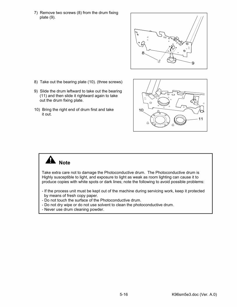
K96sm5e3.doc (Ver. A.0) 5-16
7) Remove two screws (8) from the drum fixing plate (9). 8) Take out the bearing plate (10). (three screws) 9) Slide the drum leftward to take out the bearing (11) and then slide it rightward again to take out the drum fixing plate. 10) Bring the right end of drum first and take it out.
Note Take extra care not to damage the Photoconductive drum. The Photoconductive drum is Highly susceptible to light, and exposure to light as weak as room lighting can cause it to produce copies with white spots or dark lines; note the following to avoid possible problems: - If the process unit must be kept out of the machine during servicing work, keep it protected by means of fresh copy paper. - Do not touch the surface of the Photoconductive drum. - Do not dry wipe or do not use solvent to clean the photoconductive drum. - Never use drum cleaning powder.
9
8
11
10
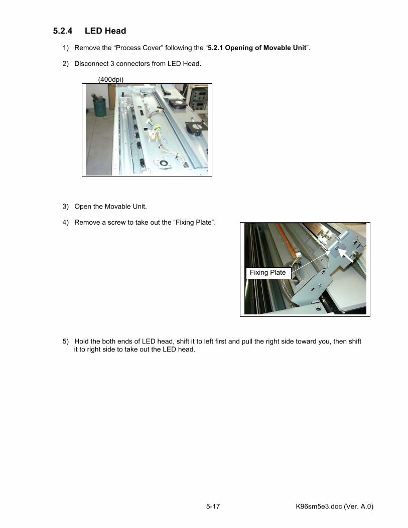
K96sm5e3.doc (Ver. A.0) 5-17
5.2.4 LED Head 1) Remove the “Process Cover” following the “5.2.1 Opening of Movable Unit”. 2) Disconnect 3 connectors from LED Head. (400dpi) 3) Open the Movable Unit. 4) Remove a screw to take out the “Fixing Plate”. 5) Hold the both ends of LED head, shift it to left first and pull the right side toward you, then shift it to right side to take out the LED head.
Fixing Plate
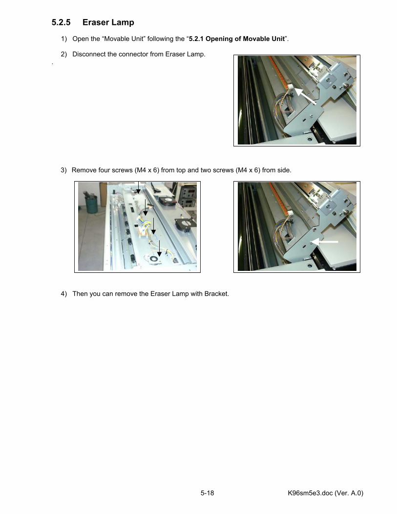
K96sm5e3.doc (Ver. A.0) 5-18
5.2.5 Eraser Lamp 1) Open the “Movable Unit” following the “5.2.1 Opening of Movable Unit”. 2) Disconnect the connector from Eraser Lamp. .
3) Remove four screws (M4 x 6) from top and two screws (M4 x 6) from side. 4) Then you can remove the Eraser Lamp with Bracket.
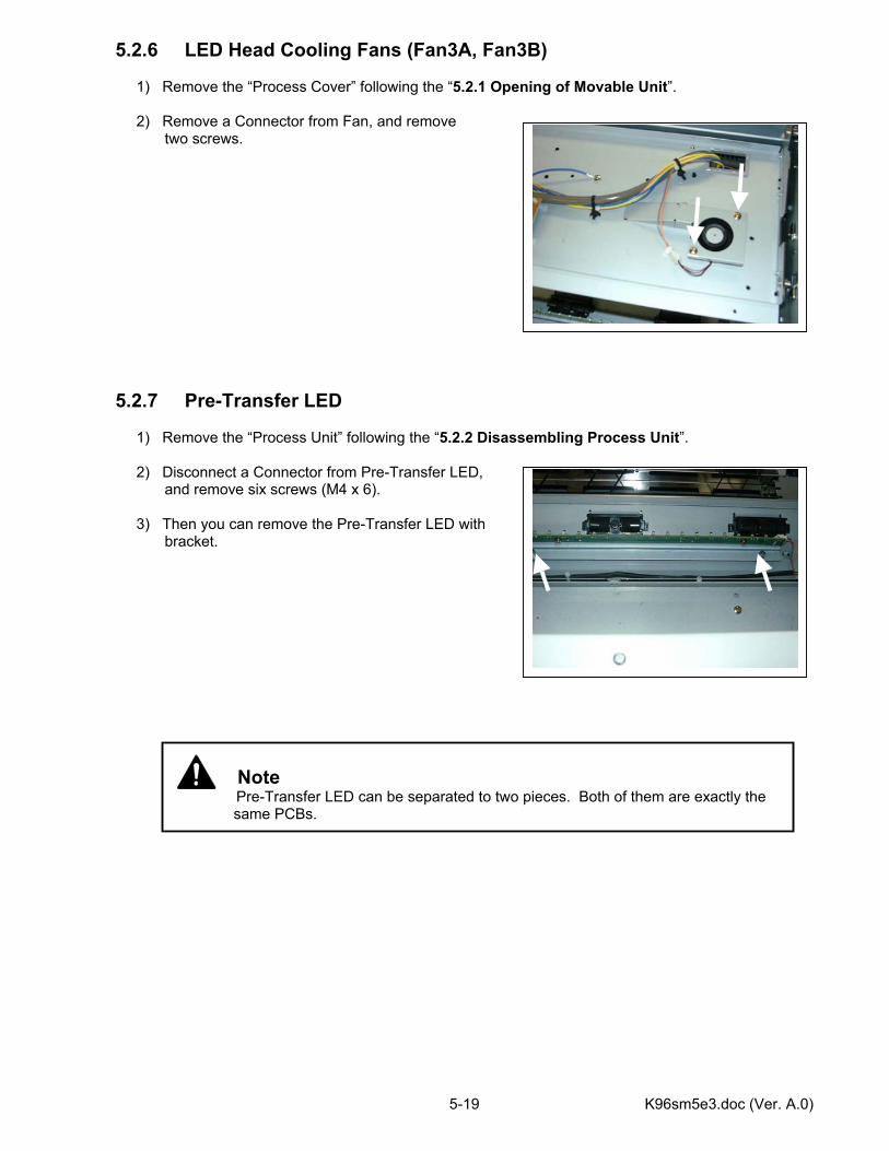
K96sm5e3.doc (Ver. A.0) 5-19
5.2.6 LED Head Cooling Fans (Fan3A, Fan3B) 1) Remove the “Process Cover” following the “5.2.1 Opening of Movable Unit”. 2) Remove a Connector from Fan, and remove two screws. 5.2.7 Pre-Transfer LED 1) Remove the “Process Unit” following the “5.2.2 Disassembling Process Unit”. 2) Disconnect a Connector from Pre-Transfer LED, and remove six screws (M4 x 6). 3) Then you can remove the Pre-Transfer LED with bracket.
Note Pre-Transfer LED can be separated to two pieces. Both of them are exactly the
same PCBs.
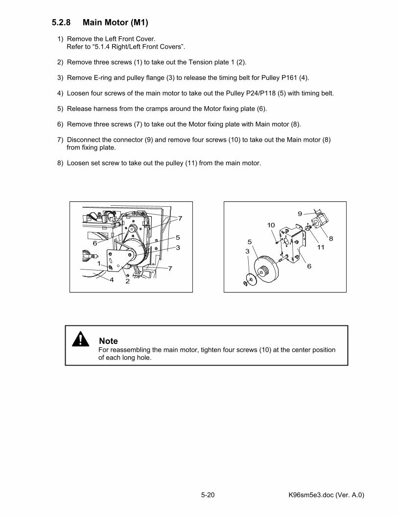
K96sm5e3.doc (Ver. A.0) 5-20
5.2.8 Main Motor (M1) 1) Remove the Left Front Cover. Refer to “5.1.4 Right/Left Front Covers”. 2) Remove three screws (1) to take out the Tension plate 1 (2). 3) Remove E-ring and pulley flange (3) to release the timing belt for Pulley P161 (4). 4) Loosen four screws of the main motor to take out the Pulley P24/P118 (5) with timing belt. 5) Release harness from the cramps around the Motor fixing plate (6). 6) Remove three screws (7) to take out the Motor fixing plate with Main motor (8). 7) Disconnect the connector (9) and remove four screws (10) to take out the Main motor (8) from fixing plate. 8) Loosen set screw to take out the pulley (11) from the main motor.
Note For reassembling the main motor, tighten four screws (10) at the center position of each long hole.
1
2
3
4
56
7
7
35
6
9
10
118
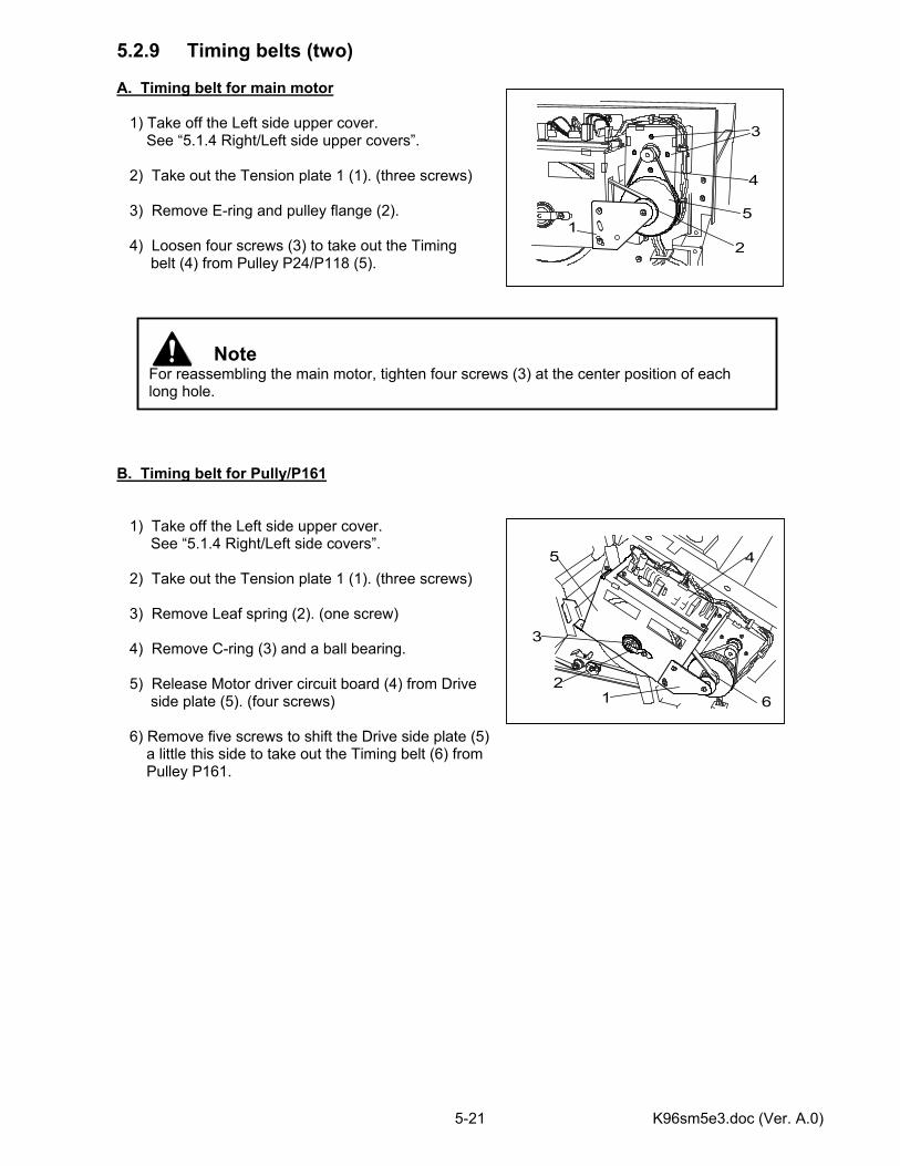
K96sm5e3.doc (Ver. A.0) 5-21
5.2.9 Timing belts (two) A. Timing belt for main motor 1) Take off the Left side upper cover. See “5.1.4 Right/Left side upper covers”. 2) Take out the Tension plate 1 (1). (three screws) 3) Remove E-ring and pulley flange (2). 4) Loosen four screws (3) to take out the Timing belt (4) from Pulley P24/P118 (5). B. Timing belt for Pully/P161 1) Take off the Left side upper cover. See “5.1.4 Right/Left side covers”. 2) Take out the Tension plate 1 (1). (three screws) 3) Remove Leaf spring (2). (one screw) 4) Remove C-ring (3) and a ball bearing. 5) Release Motor driver circuit board (4) from Drive side plate (5). (four screws) 6) Remove five screws to shift the Drive side plate (5) a little this side to take out the Timing belt (6) from Pulley P161.
Note For reassembling the main motor, tighten four screws (3) at the center position of each long hole.
12
3
4
5
12
3
45
6
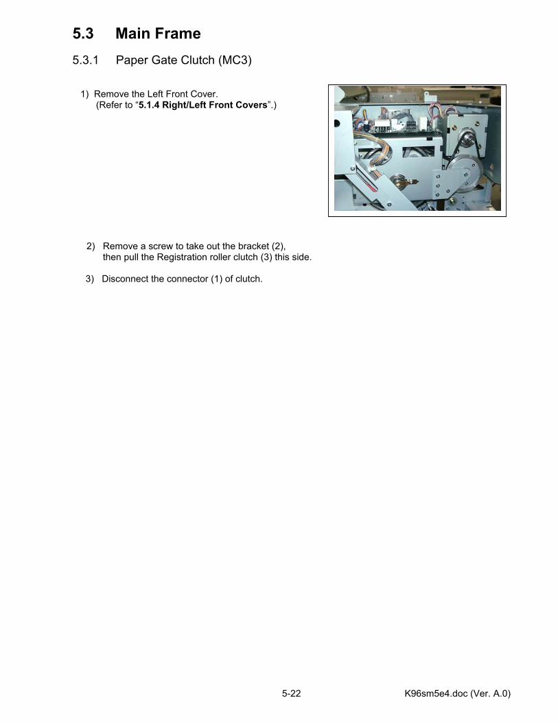
K96sm5e4.doc (Ver. A.0) 5-22
5.3 Main Frame 5.3.1 Paper Gate Clutch (MC3) 1) Remove the Left Front Cover.
(Refer to “5.1.4 Right/Left Front Covers”.)
2) Remove a screw to take out the bracket (2),
then pull the Registration roller clutch (3) this side. 3) Disconnect the connector (1) of clutch.
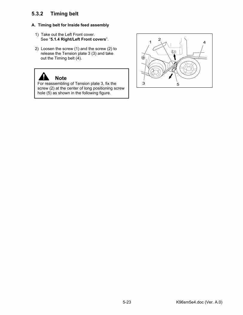
K96sm5e4.doc (Ver. A.0) 5-23
5.3.2 Timing belt A. Timing belt for Inside feed assembly 1) Take out the Left Front cover. See “5.1.4 Right/Left Front covers”. 2) Loosen the screw (1) and the screw (2) to release the Tension plate 3 (3) and take out the Timing belt (4).
Note For reassembling of Tension plate 3, fix the screw (2) at the center of long positioning screw hole (5) as shown in the following figure.
1 2
3
4
5
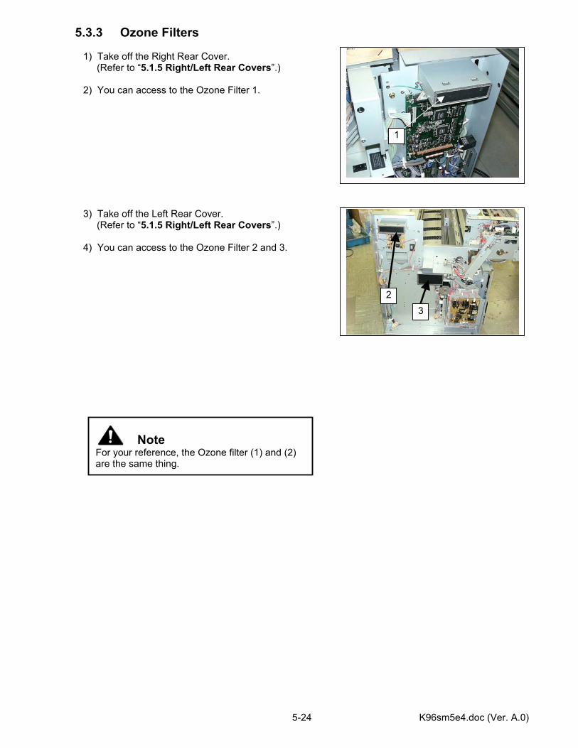
K96sm5e4.doc (Ver. A.0) 5-24
5.3.3 Ozone Filters 1) Take off the Right Rear Cover. (Refer to “5.1.5 Right/Left Rear Covers”.) 2) You can access to the Ozone Filter 1.
3) Take off the Left Rear Cover. (Refer to “5.1.5 Right/Left Rear Covers”.) 4) You can access to the Ozone Filter 2 and 3.
Note For your reference, the Ozone filter (1) and (2) are the same thing.
1
23
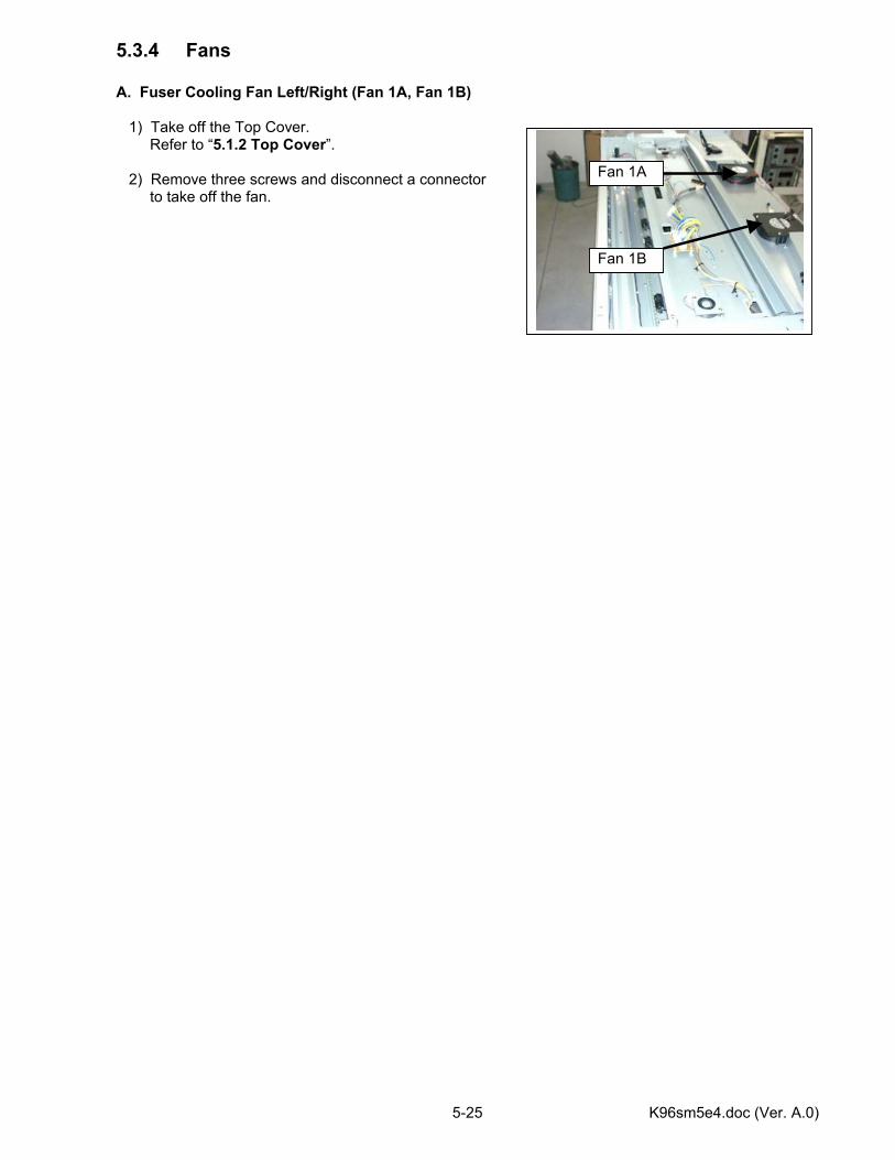
K96sm5e4.doc (Ver. A.0) 5-25
5.3.4 Fans A. Fuser Cooling Fan Left/Right (Fan 1A, Fan 1B) 1) Take off the Top Cover. Refer to “5.1.2 Top Cover”. 2) Remove three screws and disconnect a connector to take off the fan.
Fan 1A
Fan 1B
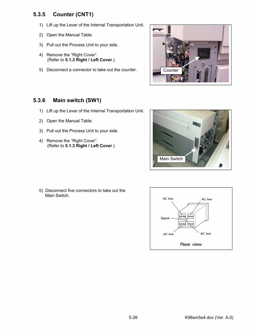
K96sm5e4.doc (Ver. A.0) 5-26
5.3.5 Counter (CNT1) 1) Lift up the Lever of the Internal Transportation Unit. 2) Open the Manual Table. 3) Pull out the Process Unit to your side. 4) Remove the “Right Cover”.
(Refer to 5.1.3 Right / Left Cover.) 5) Disconnect a connector to take out the counter. 5.3.6 Main switch (SW1) 1) Lift up the Lever of the Internal Transportation Unit. 2) Open the Manual Table. 3) Pull out the Process Unit to your side. 4) Remove the “Right Cover”.
(Refer to 5.1.3 Right / Left Cover.) 5) Disconnect five connectors to take out the Main Switch.
Rear view
blue
blue
white
white
AC line
Signal
AC line
AC line AC line
Counter
Main Switch
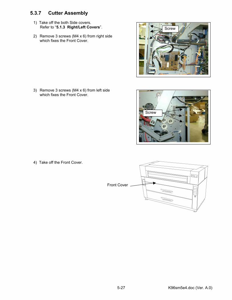
K96sm5e4.doc (Ver. A.0) 5-27
5.3.7 Cutter Assembly 1) Take off the both Side covers.
Refer to “5.1.3 Right/Left Covers”.
2) Remove 3 screws (M4 x 6) from right side which fixes the Front Cover.
3) Remove 3 screws (M4 x 6) from left side which fixes the Front Cover.
4) Take off the Front Cover. Front Cover
Screw
Screw
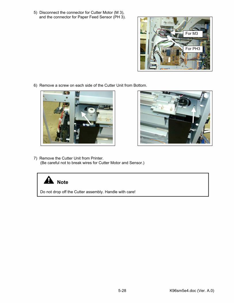
K96sm5e4.doc (Ver. A.0) 5-28
5) Disconnect the connector for Cutter Motor (M 3), and the connector for Paper Feed Sensor (PH 3).
6) Remove a screw on each side of the Cutter Unit from Bottom. 7) Remove the Cutter Unit from Printer. (Be careful not to break wires for Cutter Motor and Sensor.)
Note Do not drop off the Cutter assembly. Handle with care!
For M3
For PH3
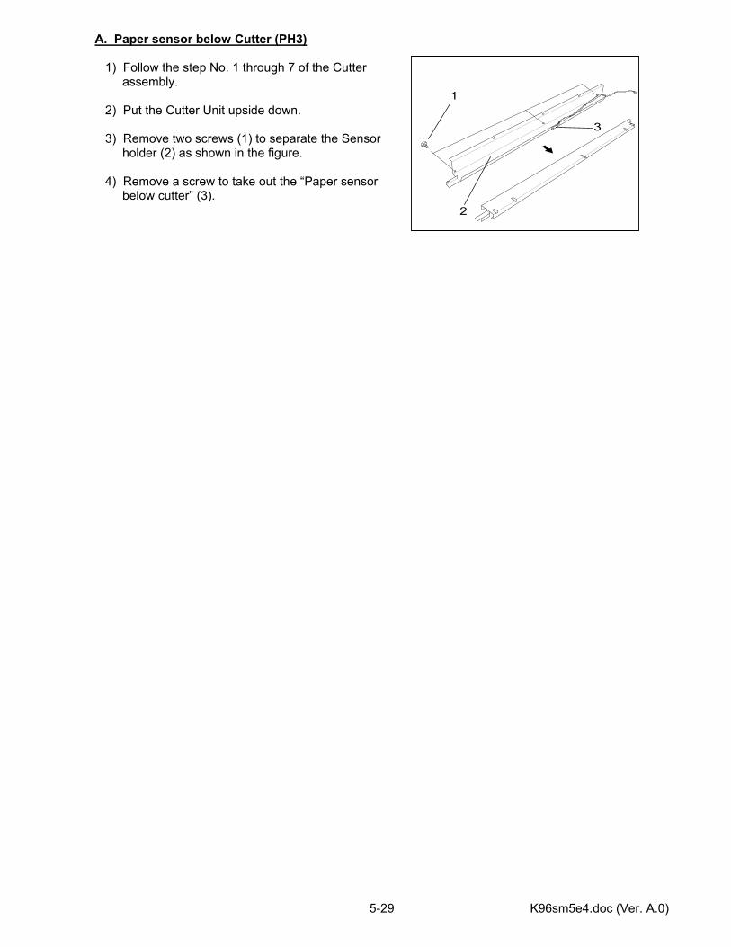
K96sm5e4.doc (Ver. A.0) 5-29
A. Paper sensor below Cutter (PH3) 1) Follow the step No. 1 through 7 of the Cutter assembly. 2) Put the Cutter Unit upside down. 3) Remove two screws (1) to separate the Sensor holder (2) as shown in the figure. 4) Remove a screw to take out the “Paper sensor below cutter” (3).
2
1
3
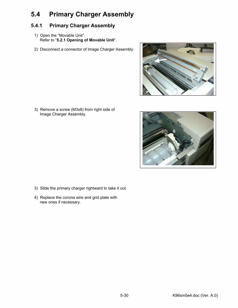
K96sm5e4.doc (Ver. A.0) 5-30
5.4 Primary Charger Assembly 5.4.1 Primary Charger Assembly 1) Open the “Movable Unit”. Refer to “5.2.1 Opening of Movable Unit”. 2) Disconnect a connector of Image Charger Assembly. 3) Remove a screw (M3x8) from right side of Image Charger Assembly. 3) Slide the primary charger rightward to take it out. 4) Replace the corona wire and grid plate with new ones if necessary.
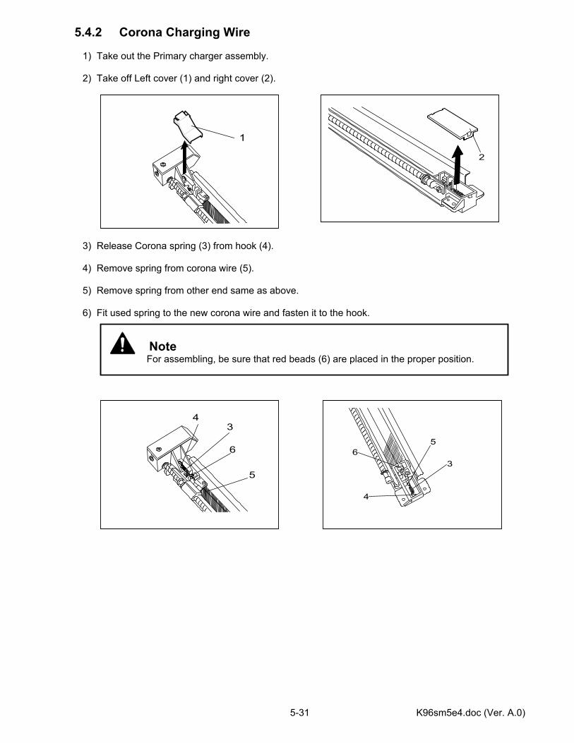
K96sm5e4.doc (Ver. A.0) 5-31
5.4.2 Corona Charging Wire 1) Take out the Primary charger assembly. 2) Take off Left cover (1) and right cover (2). 3) Release Corona spring (3) from hook (4). 4) Remove spring from corona wire (5). 5) Remove spring from other end same as above. 6) Fit used spring to the new corona wire and fasten it to the hook.
Note
For assembling, be sure that red beads (6) are placed in the proper position.
1
4
3
6
5
2
3
4
56
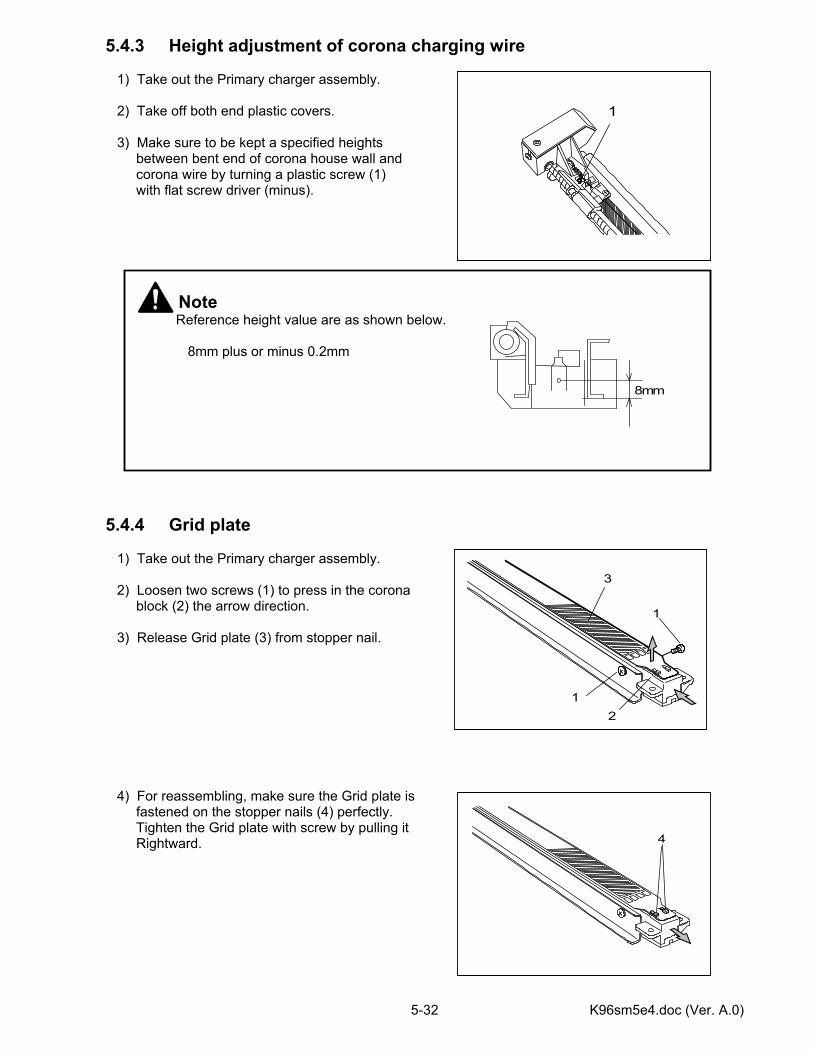
K96sm5e4.doc (Ver. A.0) 5-32
5.4.3 Height adjustment of corona charging wire 1) Take out the Primary charger assembly. 2) Take off both end plastic covers. 3) Make sure to be kept a specified heights between bent end of corona house wall and corona wire by turning a plastic screw (1) with flat screw driver (minus). 5.4.4 Grid plate 1) Take out the Primary charger assembly. 2) Loosen two screws (1) to press in the corona block (2) the arrow direction. 3) Release Grid plate (3) from stopper nail. 4) For reassembling, make sure the Grid plate is fastened on the stopper nails (4) perfectly. Tighten the Grid plate with screw by pulling it Rightward.
Note
Reference height value are as shown below.
8mm plus or minus 0.2mm
8mm
1
3
1
21
4
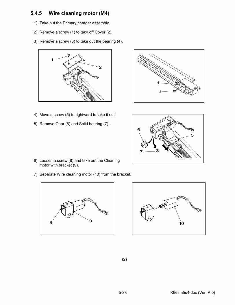
K96sm5e4.doc (Ver. A.0) 5-33
5.4.5 Wire cleaning motor (M4) 1) Take out the Primary charger assembly. 2) Remove a screw (1) to take off Cover (2). 3) Remove a screw (3) to take out the bearing (4). 4) Move a screw (5) to rightward to take it out. 5) Remove Gear (6) and Solid bearing (7). 6) Loosen a screw (8) and take out the Cleaning motor with bracket (9). 7) Separate Wire cleaning motor (10) from the bracket.
(2)
1
2
8 9
10
3
4
56
7
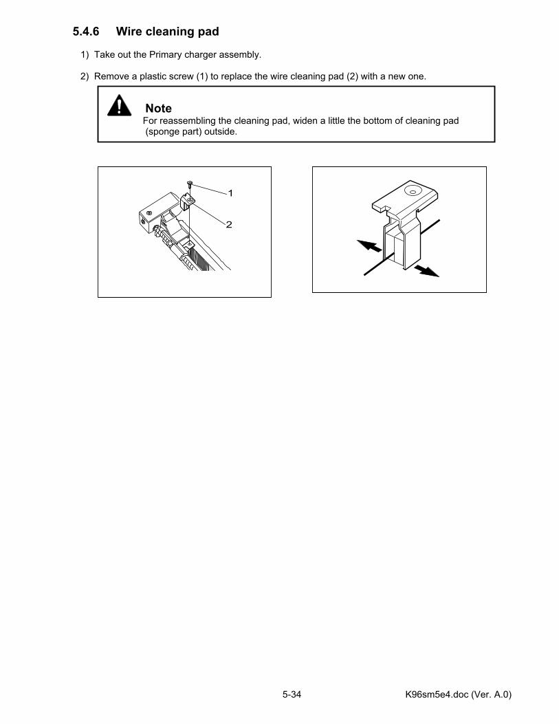
K96sm5e4.doc (Ver. A.0) 5-34
5.4.6 Wire cleaning pad 1) Take out the Primary charger assembly. 2) Remove a plastic screw (1) to replace the wire cleaning pad (2) with a new one.
Note
For reassembling the cleaning pad, widen a little the bottom of cleaning pad (sponge part) outside.
1
2
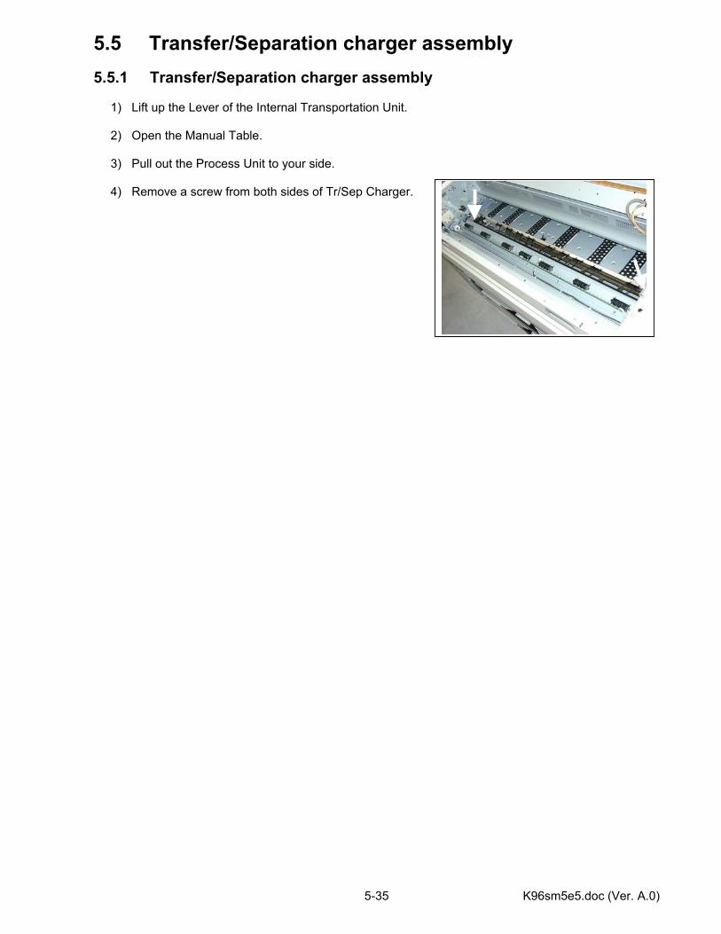
K96sm5e5.doc (Ver. A.0) 5-35
5.5 Transfer/Separation charger assembly 5.5.1 Transfer/Separation charger assembly 1) Lift up the Lever of the Internal Transportation Unit. 2) Open the Manual Table. 3) Pull out the Process Unit to your side. 4) Remove a screw from both sides of Tr/Sep Charger.
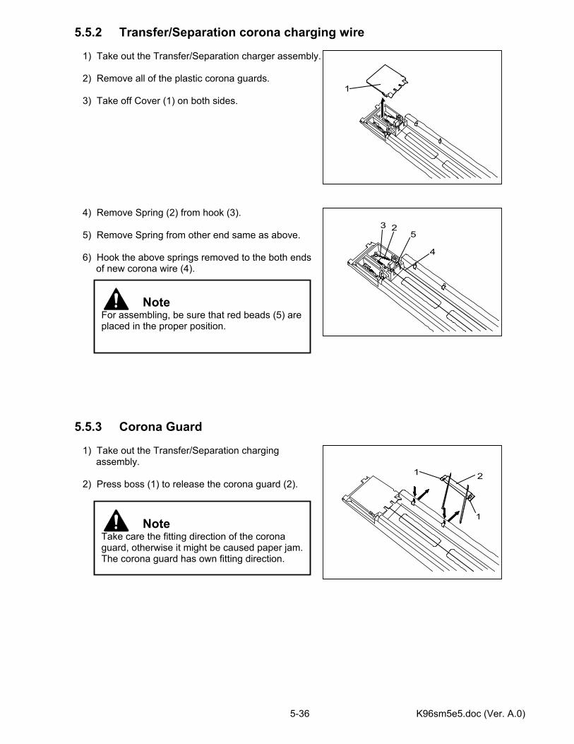
K96sm5e5.doc (Ver. A.0) 5-36
5.5.2 Transfer/Separation corona charging wire 1) Take out the Transfer/Separation charger assembly. 2) Remove all of the plastic corona guards. 3) Take off Cover (1) on both sides. 4) Remove Spring (2) from hook (3). 5) Remove Spring from other end same as above. 6) Hook the above springs removed to the both ends of new corona wire (4). 5.5.3 Corona Guard 1) Take out the Transfer/Separation charging assembly. 2) Press boss (1) to release the corona guard (2).
Note Take care the fitting direction of the corona guard, otherwise it might be caused paper jam.The corona guard has own fitting direction.
Note For assembling, be sure that red beads (5) areplaced in the proper position.
1
23
4
5
1
21
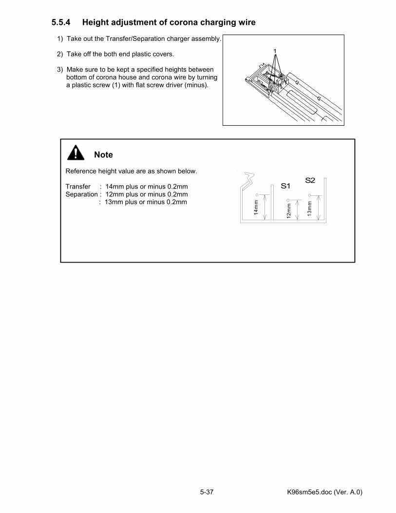
K96sm5e5.doc (Ver. A.0) 5-37
5.5.4 Height adjustment of corona charging wire 1) Take out the Transfer/Separation charger assembly. 2) Take off the both end plastic covers. 3) Make sure to be kept a specified heights between bottom of corona house and corona wire by turning a plastic screw (1) with flat screw driver (minus).
Note Reference height value are as shown below. Transfer : 14mm plus or minus 0.2mm Separation : 12mm plus or minus 0.2mm
: 13mm plus or minus 0.2mm
1
14m
m
12m
m
13m
m
S1S2
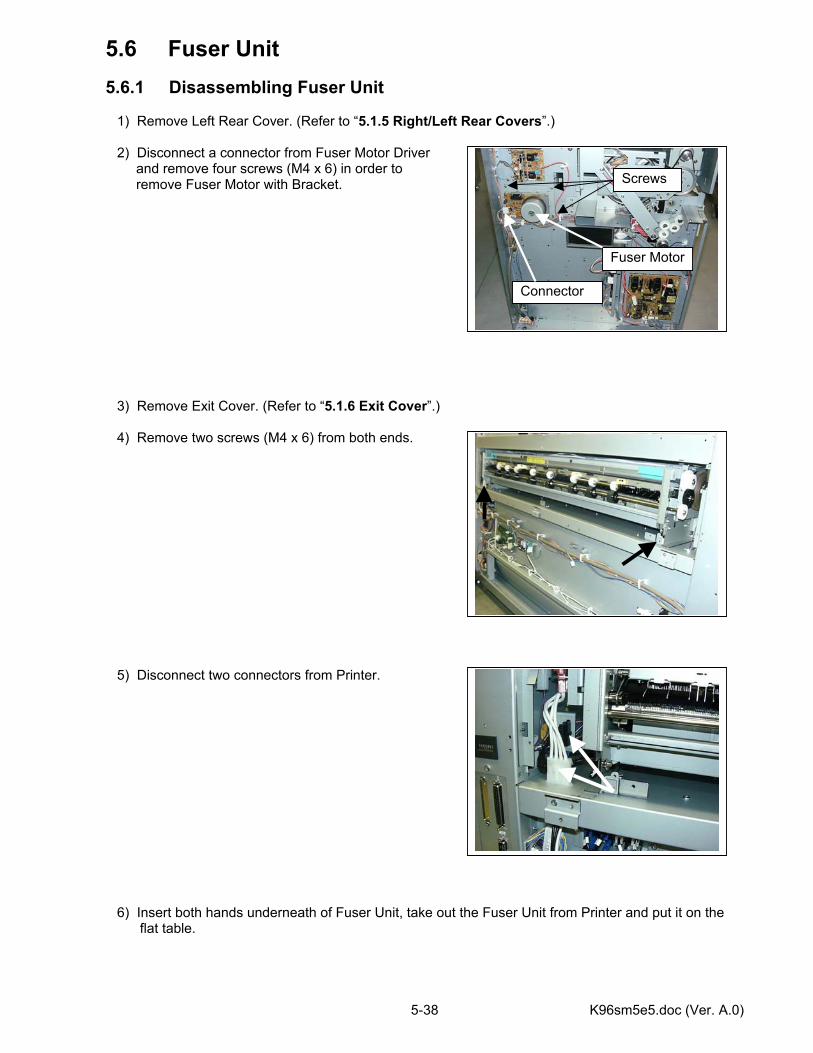
K96sm5e5.doc (Ver. A.0) 5-38
5.6 Fuser Unit 5.6.1 Disassembling Fuser Unit 1) Remove Left Rear Cover. (Refer to “5.1.5 Right/Left Rear Covers”.) 2) Disconnect a connector from Fuser Motor Driver and remove four screws (M4 x 6) in order to remove Fuser Motor with Bracket. 3) Remove Exit Cover. (Refer to “5.1.6 Exit Cover”.) 4) Remove two screws (M4 x 6) from both ends. 5) Disconnect two connectors from Printer. 6) Insert both hands underneath of Fuser Unit, take out the Fuser Unit from Printer and put it on the
flat table.
Fuser Motor
Connector
Screws
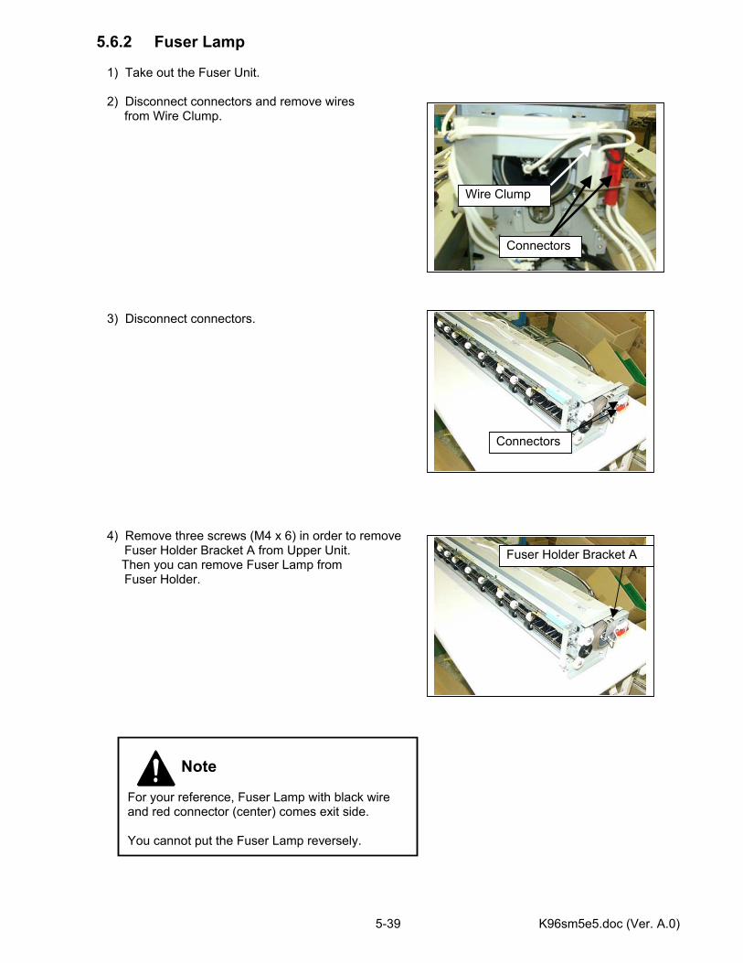
K96sm5e5.doc (Ver. A.0) 5-39
5.6.2 Fuser Lamp 1) Take out the Fuser Unit. 2) Disconnect connectors and remove wires from Wire Clump. 3) Disconnect connectors. 4) Remove three screws (M4 x 6) in order to remove Fuser Holder Bracket A from Upper Unit.
Then you can remove Fuser Lamp from Fuser Holder.
Connectors
Wire Clump
Connectors
Note For your reference, Fuser Lamp with black wire and red connector (center) comes exit side. You cannot put the Fuser Lamp reversely.
Fuser Holder Bracket A
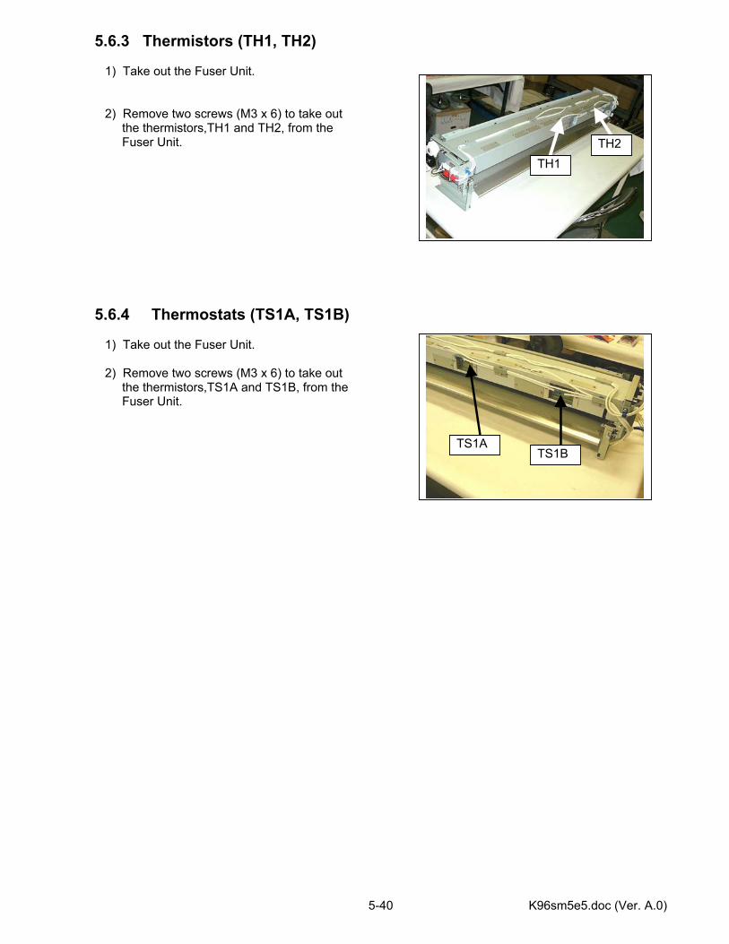
K96sm5e5.doc (Ver. A.0) 5-40
5.6.3 Thermistors (TH1, TH2) 1) Take out the Fuser Unit. 2) Remove two screws (M3 x 6) to take out the thermistors,TH1 and TH2, from the Fuser Unit. 5.6.4 Thermostats (TS1A, TS1B) 1) Take out the Fuser Unit. 2) Remove two screws (M3 x 6) to take out the thermistors,TS1A and TS1B, from the Fuser Unit.
TH1 TH2
TS1ATS1B
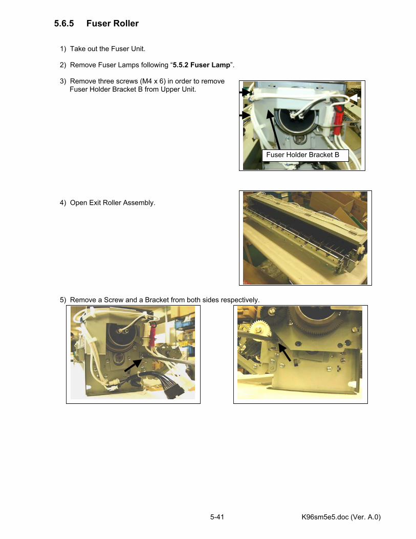
K96sm5e5.doc (Ver. A.0) 5-41
5.6.5 Fuser Roller 1) Take out the Fuser Unit. 2) Remove Fuser Lamps following “5.5.2 Fuser Lamp”. 3) Remove three screws (M4 x 6) in order to remove Fuser Holder Bracket B from Upper Unit. 4) Open Exit Roller Assembly. 5) Remove a Screw and a Bracket from both sides respectively.
Fuser Holder Bracket B
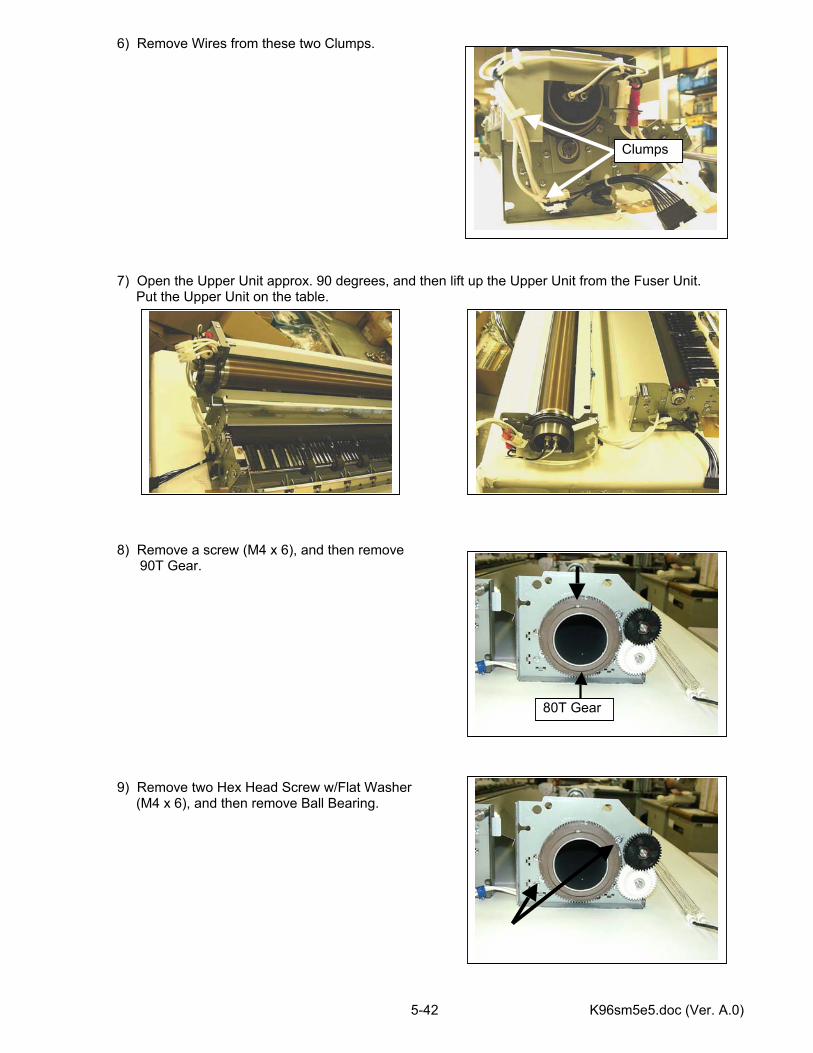
K96sm5e5.doc (Ver. A.0) 5-42
6) Remove Wires from these two Clumps. 7) Open the Upper Unit approx. 90 degrees, and then lift up the Upper Unit from the Fuser Unit. Put the Upper Unit on the table. 8) Remove a screw (M4 x 6), and then remove
90T Gear. 9) Remove two Hex Head Screw w/Flat Washer (M4 x 6), and then remove Ball Bearing.
Clumps
80T Gear
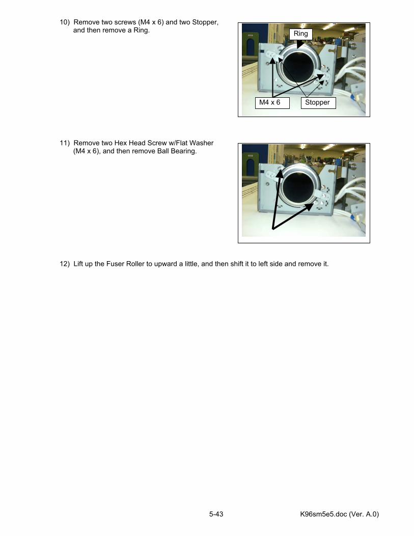
K96sm5e5.doc (Ver. A.0) 5-43
10) Remove two screws (M4 x 6) and two Stopper, and then remove a Ring. 11) Remove two Hex Head Screw w/Flat Washer (M4 x 6), and then remove Ball Bearing. 12) Lift up the Fuser Roller to upward a little, and then shift it to left side and remove it.
M4 x 6
Ring
Stopper
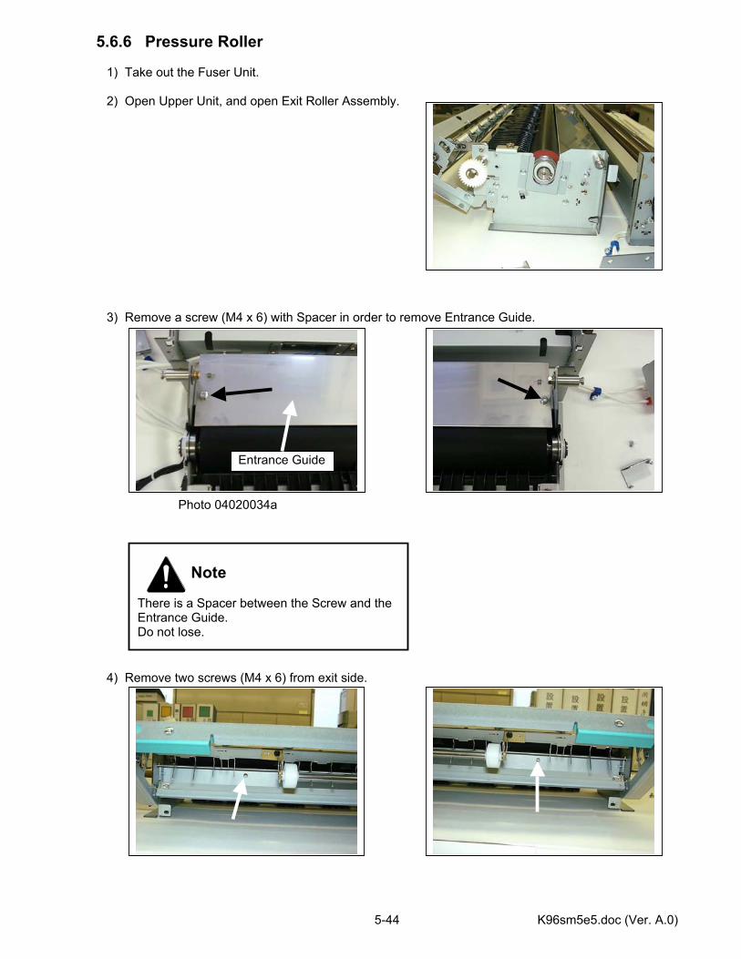
K96sm5e5.doc (Ver. A.0) 5-44
5.6.6 Pressure Roller 1) Take out the Fuser Unit. 2) Open Upper Unit, and open Exit Roller Assembly. 3) Remove a screw (M4 x 6) with Spacer in order to remove Entrance Guide. Photo 04020034a 4) Remove two screws (M4 x 6) from exit side.
Entrance Guide
Note There is a Spacer between the Screw and the Entrance Guide. Do not lose.
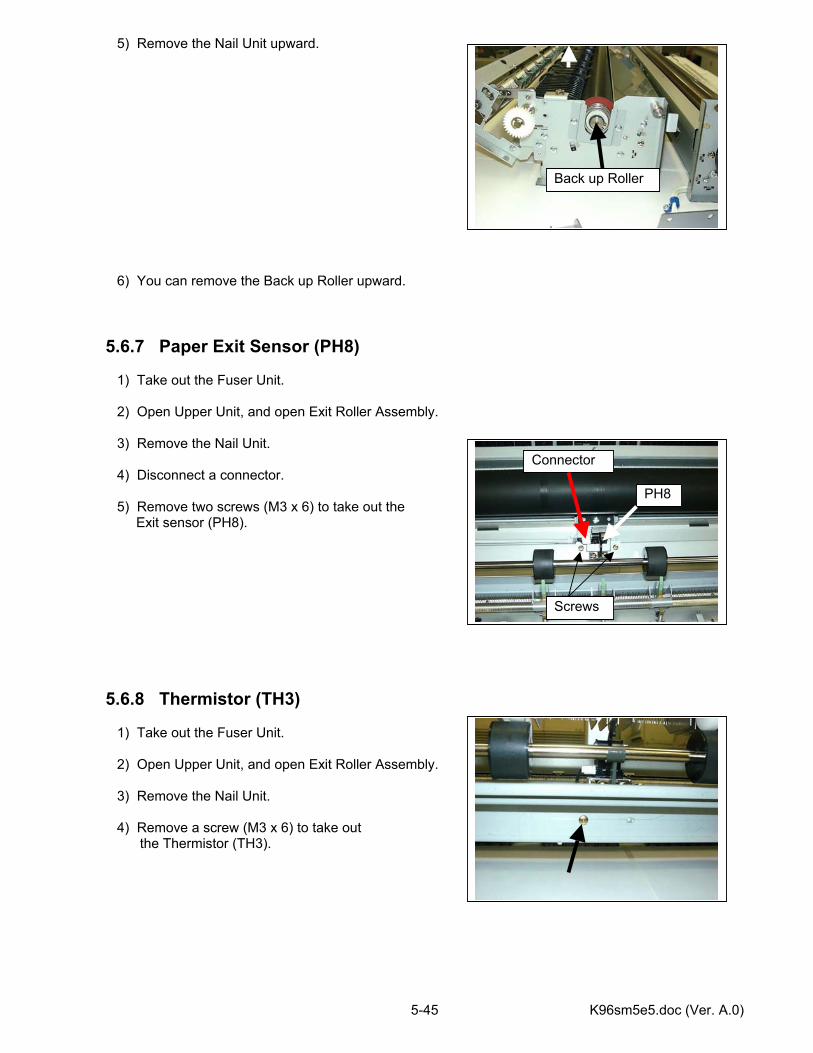
K96sm5e5.doc (Ver. A.0) 5-45
5) Remove the Nail Unit upward. 6) You can remove the Back up Roller upward. 5.6.7 Paper Exit Sensor (PH8) 1) Take out the Fuser Unit. 2) Open Upper Unit, and open Exit Roller Assembly. 3) Remove the Nail Unit. 4) Disconnect a connector. 5) Remove two screws (M3 x 6) to take out the Exit sensor (PH8). 5.6.8 Thermistor (TH3) 1) Take out the Fuser Unit. 2) Open Upper Unit, and open Exit Roller Assembly. 3) Remove the Nail Unit. 4) Remove a screw (M3 x 6) to take out
the Thermistor (TH3).
Back up Roller
Connector
Screws
PH8
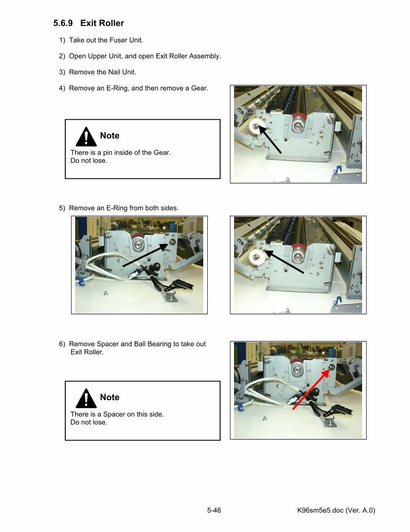
K96sm5e5.doc (Ver. A.0) 5-46
5.6.9 Exit Roller 1) Take out the Fuser Unit. 2) Open Upper Unit, and open Exit Roller Assembly. 3) Remove the Nail Unit. 4) Remove an E-Ring, and then remove a Gear. 5) Remove an E-Ring from both sides. 6) Remove Spacer and Ball Bearing to take out
Exit Roller.
Note There is a pin inside of the Gear. Do not lose.
Note There is a Spacer on this side. Do not lose.
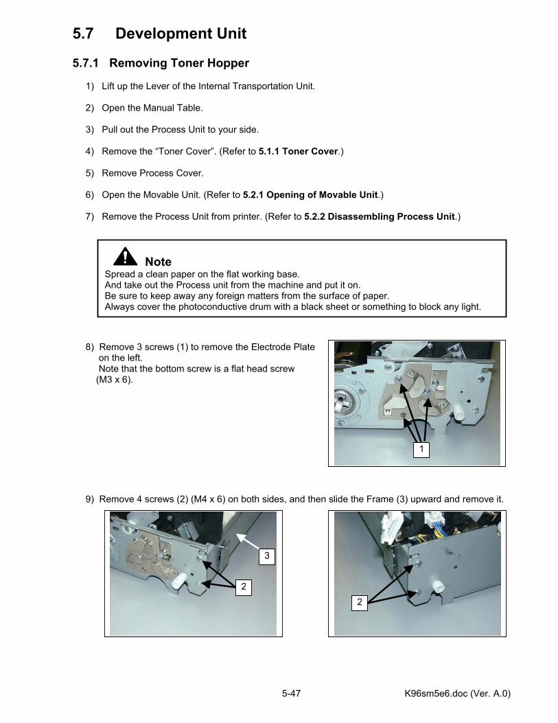
K96sm5e6.doc (Ver. A.0) 5-47
5.7 Development Unit 5.7.1 Removing Toner Hopper 1) Lift up the Lever of the Internal Transportation Unit. 2) Open the Manual Table. 3) Pull out the Process Unit to your side. 4) Remove the “Toner Cover”. (Refer to 5.1.1 Toner Cover.) 5) Remove Process Cover. 6) Open the Movable Unit. (Refer to 5.2.1 Opening of Movable Unit.) 7) Remove the Process Unit from printer. (Refer to 5.2.2 Disassembling Process Unit.) 8) Remove 3 screws (1) to remove the Electrode Plate on the left. Note that the bottom screw is a flat head screw
(M3 x 6). 9) Remove 4 screws (2) (M4 x 6) on both sides, and then slide the Frame (3) upward and remove it.
Note Spread a clean paper on the flat working base. And take out the Process unit from the machine and put it on. Be sure to keep away any foreign matters from the surface of paper. Always cover the photoconductive drum with a black sheet or something to block any light.
1
2
3
2
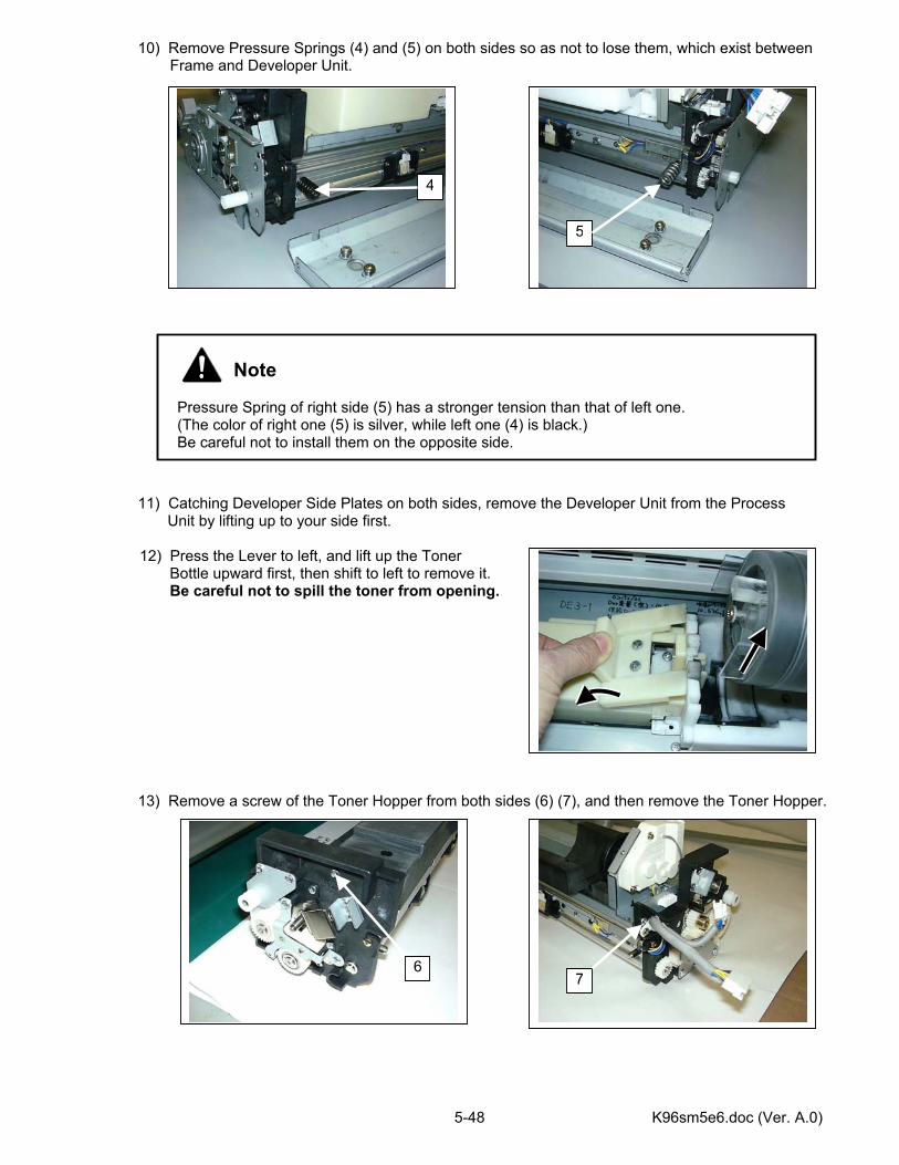
K96sm5e6.doc (Ver. A.0) 5-48
10) Remove Pressure Springs (4) and (5) on both sides so as not to lose them, which exist between Frame and Developer Unit.
11) Catching Developer Side Plates on both sides, remove the Developer Unit from the Process Unit by lifting up to your side first.
12) Press the Lever to left, and lift up the Toner Bottle upward first, then shift to left to remove it. Be careful not to spill the toner from opening.
13) Remove a screw of the Toner Hopper from both sides (6) (7), and then remove the Toner Hopper.
Note Pressure Spring of right side (5) has a stronger tension than that of left one. (The color of right one (5) is silver, while left one (4) is black.) Be careful not to install them on the opposite side.
4
5
67
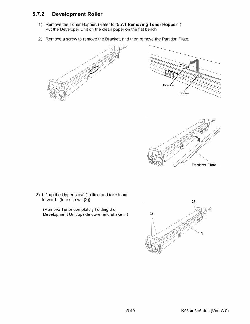
K96sm5e6.doc (Ver. A.0) 5-49
5.7.2 Development Roller 1) Remove the Toner Hopper. (Refer to “5.7.1 Removing Toner Hopper”.) Put the Developer Unit on the clean paper on the flat bench. 2) Remove a screw to remove the Bracket, and then remove the Partition Plate. 3) Lift up the Upper stay(1) a little and take it out forward. (four screws (2))
(Remove Toner completely holding the Development Unit upside down and shake it.)
Screw
Bracket
Partition Plate
1
2
2
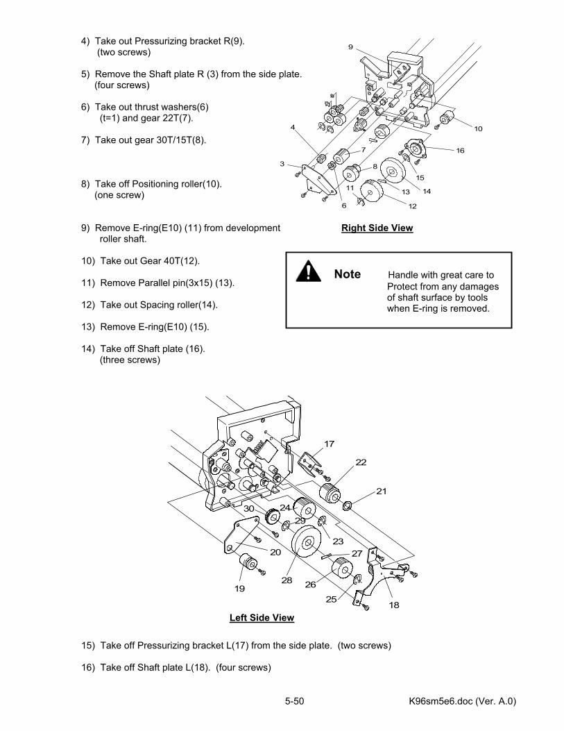
K96sm5e6.doc (Ver. A.0) 5-50
3
4
6
7
8
9
10
11
12
13 14
15
16
4) Take out Pressurizing bracket R(9). (two screws) 5) Remove the Shaft plate R (3) from the side plate. (four screws) 6) Take out thrust washers(6) (t=1) and gear 22T(7). 7) Take out gear 30T/15T(8). 8) Take off Positioning roller(10). (one screw) 9) Remove E-ring(E10) (11) from development Right Side View roller shaft. 10) Take out Gear 40T(12). 11) Remove Parallel pin(3x15) (13). 12) Take out Spacing roller(14). 13) Remove E-ring(E10) (15). 14) Take off Shaft plate (16). (three screws) 15) Take off Pressurizing bracket L(17) from the side plate. (two screws) 16) Take off Shaft plate L(18). (four screws)
Left Side View
17
18
19
2023
21
22
24
25
26
27
28
2930
Note Handle with great care to Protect from any damages
of shaft surface by tools when E-ring is removed.
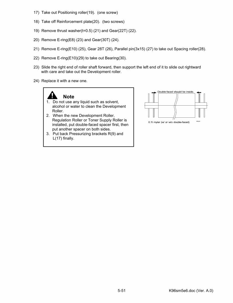
K96sm5e6.doc (Ver. A.0) 5-51
17) Take out Positioning roller(19). (one screw) 18) Take off Reinforcement plate(20). (two screws) 19) Remove thrust washer(t=0.5) (21) and Gear(22T) (22). 20) Remove E-ring(E8) (23) and Gear(30T) (24). 21) Remove E-ring(E10) (25), Gear 28T (26), Parallel pin(3x15) (27) to take out Spacing roller(28). 22) Remove E-ring(E10)(29) to take out Bearing(30). 23) Slide the right end of roller shaft forward, then support the left end of it to slide out rightward with care and take out the Development roller. 24) Replace it with a new one.
Note 1. Do not use any liquid such as solvent,
alcohol or water to clean the Development Roller.
2. When the new Development Roller, Regulation Roller or Toner Supply Roller is installed, put double-faced spacer first, then put another spacer on both sides.
3. Put back Pressurizing brackets R(9) and L(17) finally.
565.jtd
Double-faced should be inside.
0.1t mylar (w/ or w/o double-faced)
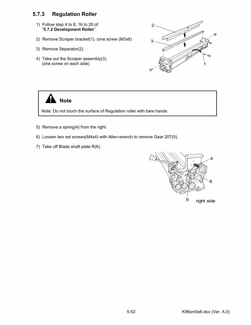
K96sm5e6.doc (Ver. A.0) 5-52
5.7.3 Regulation Roller 1) Follow step 4 to 8, 16 to 20 of “5.7.2 Development Roller”. 2) Remove Scraper bracket(1). (one screw (M3x6) 3) Remove Separator(2). 4) Take out the Scraper assembly(3). (one screw on each side) 5) Remove a spring(4) from the right. 6) Loosen two set screws(M4x4) with Allen-wrench to remove Gear 20T(5). 7) Take off Blade shaft plate R(6).
Note Note: Do not touch the surface of Regulation roller with bare hands.
1
2
3
4
5
6
right side
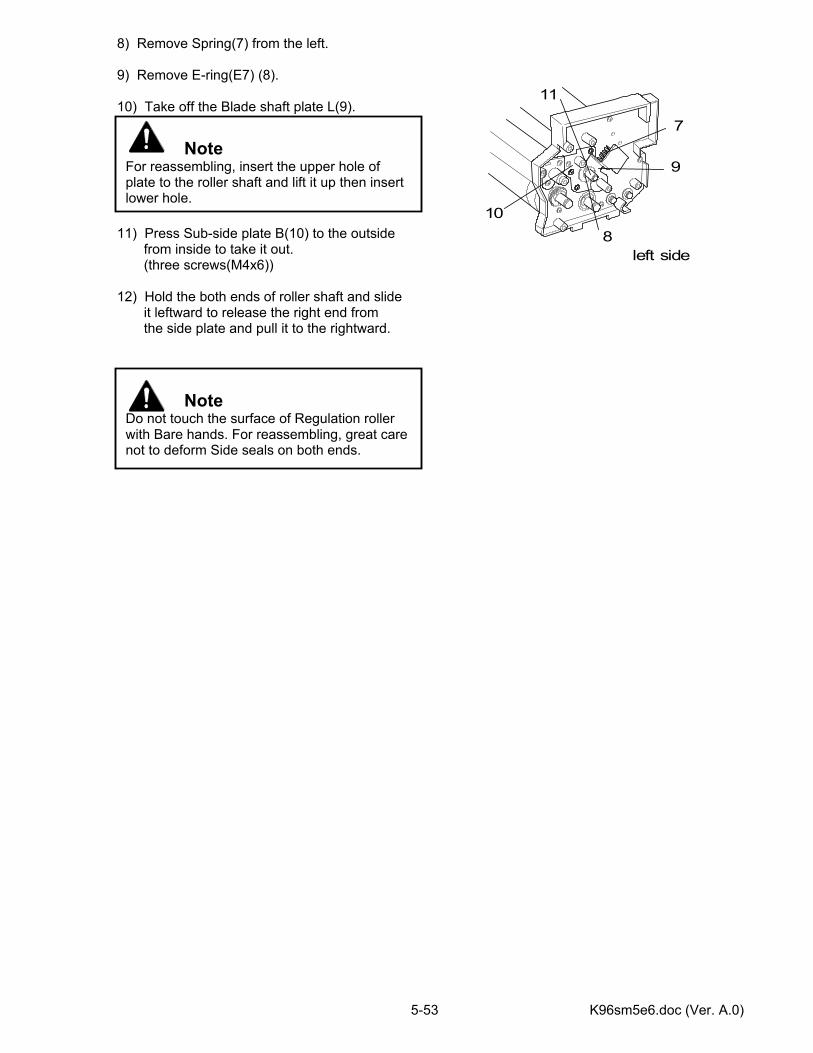
K96sm5e6.doc (Ver. A.0) 5-53
8) Remove Spring(7) from the left. 9) Remove E-ring(E7) (8). 10) Take off the Blade shaft plate L(9). 11) Press Sub-side plate B(10) to the outside from inside to take it out. (three screws(M4x6)) 12) Hold the both ends of roller shaft and slide it leftward to release the right end from the side plate and pull it to the rightward.
Note Do not touch the surface of Regulation roller with Bare hands. For reassembling, great care not to deform Side seals on both ends.
Note For reassembling, insert the upper hole of plate to the roller shaft and lift it up then insert lower hole.
7
8
9
10
11
left side
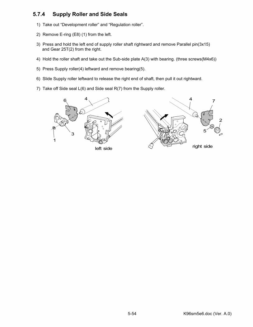
K96sm5e6.doc (Ver. A.0) 5-54
5.7.4 Supply Roller and Side Seals 1) Take out “Development roller” and “Regulation roller”. 2) Remove E-ring (E8) (1) from the left. 3) Press and hold the left end of supply roller shaft rightward and remove Parallel pin(3x15)
and Gear 25T(2) from the right. 4) Hold the roller shaft and take out the Sub-side plate A(3) with bearing. (three screws(M4x6)) 5) Press Supply roller(4) leftward and remove bearing(5). 6) Slide Supply roller leftward to release the right end of shaft, then pull it out rightward. 7) Take off Side seal L(6) and Side seal R(7) from the Supply roller.
46
31
left side
right side
2
7
5
4

K96sm5e6.doc (Ver. A.0) 5-55
[Points of note for assembling supply roller and Side seals] 1) Put back both Side seal L(1) and Side seal R(2) to the shaft before assembling. 2) Insert the left end of roller shaft to the left side plate from inside, and once run through the Side seal L to the outside. 3) Slide back the roller shaft leftward to mount the Side seal L inside. 4) Put back Sub-side plate A(4) without bearing. 5) Move the left end of roller shaft up and down and insert the bearing(5). 6) Put back the bearing(7) to the right side of roller shaft. 7) Rotate the roller shaft to seat the hole for parallel pin at level. And put back the Gear 25T(9). 8) Press and hold the roller shaft rightward, and then put the parallel pin into the groove. 9) Fix the E-ring(E8) to secure the roller shaft.
Note Be sure Side seal L/R are properly seated to the positioning boss(6mm diameter) (6),(8).
Note Be sure the groove of Gear 25T for parallel pin is also seated at level.
Note Be sure Front seal (3), Side seal L and Side seal R are not turned over and mounted correctly.
3
16
8
2
3
4
5
1
left side
right side
2
7
9

K96sm5e6.doc (Ver. A.0) 5-56
5.7.5 Sender Screw 1) Take out the Development assembly from the Process unit. 2) Take out the Toner hopper assembly. 3) Remove the Separator. 4) Remove four screws (1) to take out the Shaft plate R (2). 5) Remove one screw (4) on each side to take out the Scraper assembly (5). 6) Remove three screws (6) to take out the Agitating sheet (7). 7) Remove E-ring (8) to take out the Bush S (9). 8) Remove the screw (10) to take out the Shaft plate S (11). 9) Pull out the Agitating shaft S (12). 10) Remove E-ring (13) and the gear 20T (14). 11) Remove the bearing inside. 12) Remove E-ring (15). 13) Shift the Sender screw assembly (16) rightward. 14) Pull up from the left first, then take it out.
4
right side
14
13
12
1
2
5
6
710
16
89
415
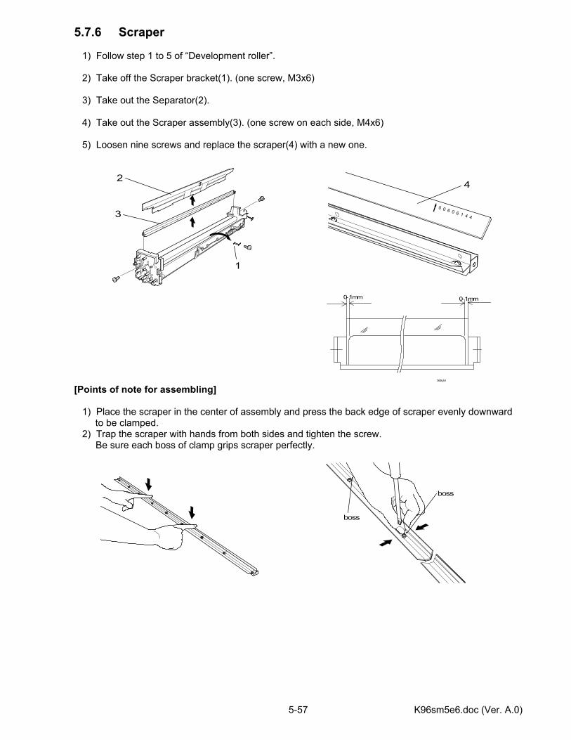
K96sm5e6.doc (Ver. A.0) 5-57
5.7.6 Scraper 1) Follow step 1 to 5 of “Development roller”. 2) Take off the Scraper bracket(1). (one screw, M3x6) 3) Take out the Separator(2). 4) Take out the Scraper assembly(3). (one screw on each side, M4x6) 5) Loosen nine screws and replace the scraper(4) with a new one. [Points of note for assembling] 1) Place the scraper in the center of assembly and press the back edge of scraper evenly downward
to be clamped. 2) Trap the scraper with hands from both sides and tighten the screw. Be sure each boss of clamp grips scraper perfectly.
boss
boss
565.jtd
0-1mm 0-1mm
0 0 6 0 6 1 4 4
4
1
2
3
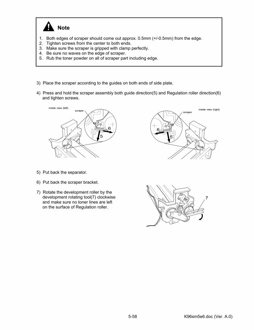
K96sm5e6.doc (Ver. A.0) 5-58
3) Place the scraper according to the guides on both ends of side plate. 4) Press and hold the scraper assembly both guide direction(5) and Regulation roller direction(6)
and tighten screws. 5) Put back the separator. 6) Put back the scraper bracket. 7) Rotate the development roller by the development rotating tool(7) clockwise and make sure no toner lines are left on the surface of Regulation roller.
Note 1. Both edges of scraper should come out approx. 0.5mm (+/-0.5mm) from the edge. 2. Tighten screws from the center to both ends. 3. Make sure the scraper is gripped with clamp perfectly. 4. Be sure no waves on the edge of scraper. 5. Rub the toner powder on all of scraper part including edge.
6
5
scraperinside view (left)
6
5
scraperinside view (right)
7
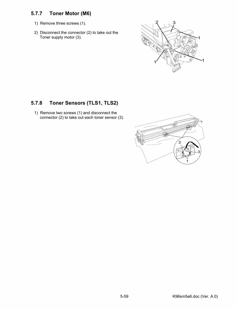
K96sm5e6.doc (Ver. A.0) 5-59
5.7.7 Toner Motor (M6) 1) Remove three screws (1). 2) Disconnect the connector (2) to take out the Toner supply motor (3). 5.7.8 Toner Sensors (TLS1, TLS2) 1) Remove two screws (1) and disconnect the connector (2) to take out each toner sensor (3).
1
2
3
32
1
11
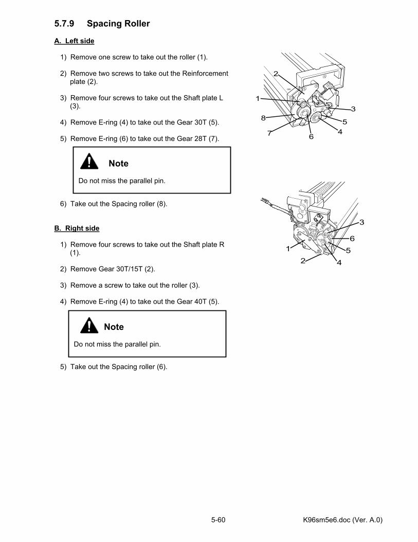
K96sm5e6.doc (Ver. A.0) 5-60
5.7.9 Spacing Roller A. Left side 1) Remove one screw to take out the roller (1). 2) Remove two screws to take out the Reinforcement plate (2). 3) Remove four screws to take out the Shaft plate L (3). 4) Remove E-ring (4) to take out the Gear 30T (5). 5) Remove E-ring (6) to take out the Gear 28T (7). 6) Take out the Spacing roller (8). B. Right side 1) Remove four screws to take out the Shaft plate R (1). 2) Remove Gear 30T/15T (2). 3) Remove a screw to take out the roller (3). 4) Remove E-ring (4) to take out the Gear 40T (5). 5) Take out the Spacing roller (6).
Note Do not miss the parallel pin.
Note Do not miss the parallel pin.
1
45
67
2
83
6
4
3
21 5
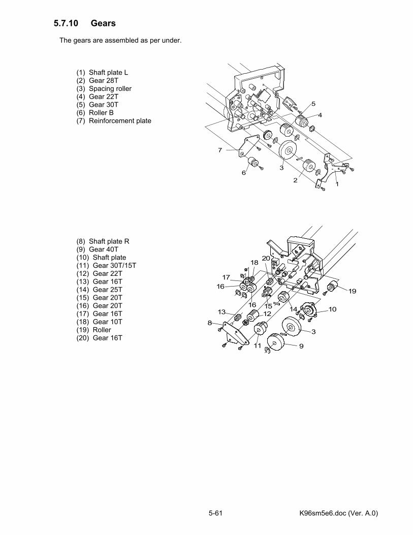
K96sm5e6.doc (Ver. A.0) 5-61
5.7.10 Gears The gears are assembled as per under. (1) Shaft plate L (2) Gear 28T (3) Spacing roller (4) Gear 22T (5) Gear 30T (6) Roller B (7) Reinforcement plate (8) Shaft plate R (9) Gear 40T (10) Shaft plate (11) Gear 30T/15T (12) Gear 22T (13) Gear 16T (14) Gear 25T (15) Gear 20T (16) Gear 20T (17) Gear 16T (18) Gear 10T (19) Roller (20) Gear 16T
12
3
4
5
6
7
16
17
15
19
14
9
13 12
11
10
18
3
16
8
20
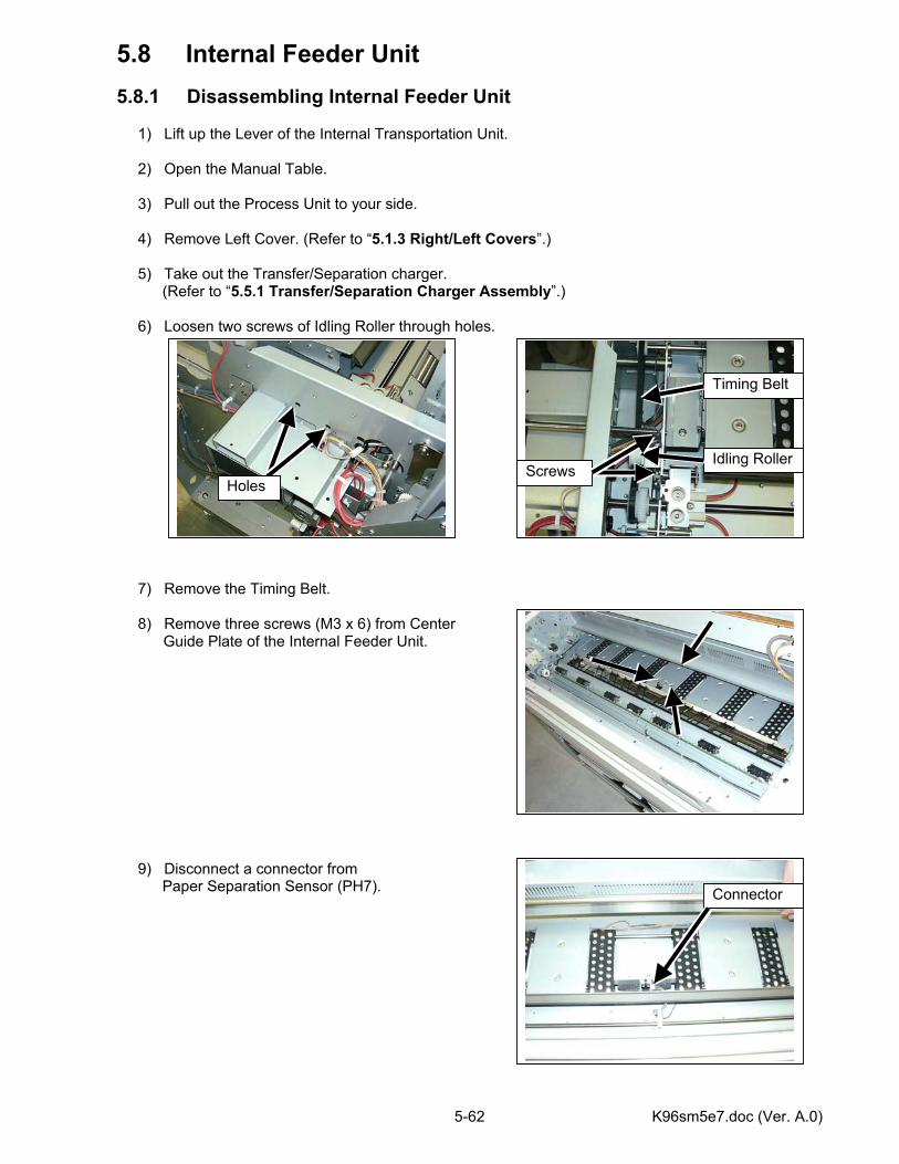
K96sm5e7.doc (Ver. A.0) 5-62
5.8 Internal Feeder Unit 5.8.1 Disassembling Internal Feeder Unit 1) Lift up the Lever of the Internal Transportation Unit. 2) Open the Manual Table. 3) Pull out the Process Unit to your side. 4) Remove Left Cover. (Refer to “5.1.3 Right/Left Covers”.) 5) Take out the Transfer/Separation charger.
(Refer to “5.5.1 Transfer/Separation Charger Assembly”.)
6) Loosen two screws of Idling Roller through holes. 7) Remove the Timing Belt. 8) Remove three screws (M3 x 6) from Center Guide Plate of the Internal Feeder Unit. 9) Disconnect a connector from
Paper Separation Sensor (PH7).
Idling Roller
Holes Screws
Timing Belt
Connector
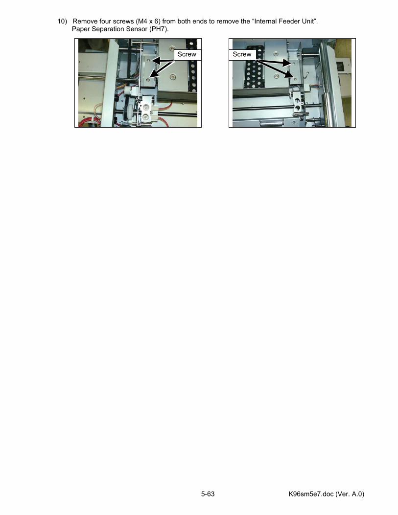
K96sm5e7.doc (Ver. A.0) 5-63
10) Remove four screws (M4 x 6) from both ends to remove the “Internal Feeder Unit”. Paper Separation Sensor (PH7).
Screw Screw
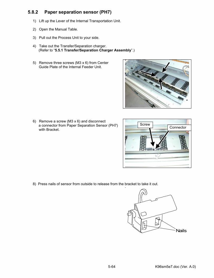
K96sm5e7.doc (Ver. A.0) 5-64
5.8.2 Paper separation sensor (PH7) 1) Lift up the Lever of the Internal Transportation Unit. 2) Open the Manual Table. 3) Pull out the Process Unit to your side. 4) Take out the Transfer/Separation charger.
(Refer to “5.5.1 Transfer/Separation Charger Assembly”.) 5) Remove three screws (M3 x 6) from Center Guide Plate of the Internal Feeder Unit. 6) Remove a screw (M3 x 6) and disconnect
a connector from Paper Separation Sensor (PH7) with Bracket. 8) Press nails of sensor from outside to release from the bracket to take it out.
Connector Screw
Nails

K96sm5e7.doc (Ver. A.0) 5-65
5.8.3 Feed belt 1) Take out the Internal Feeder Unit. (Refer to “5.8.1 Disassembling Internal Feeder Unit”.) 2) Take out the Guide plate (1). 3) Take off the feed belt (2) in the arrow direction. 5.8.4 Feed roller 1) Remove seven Guide plates (1). 2) Remove six belts (2). 3) Remove E-ring (3) and Oilless bearing (4). 4) Shift the Feed roller (5) rightward in the arrow direction to take it out.
Note Handle with care not to drop the counter roller (3) when inside feed belt is taken out further more.
1
2
3
1
2
1
2
3
4
5
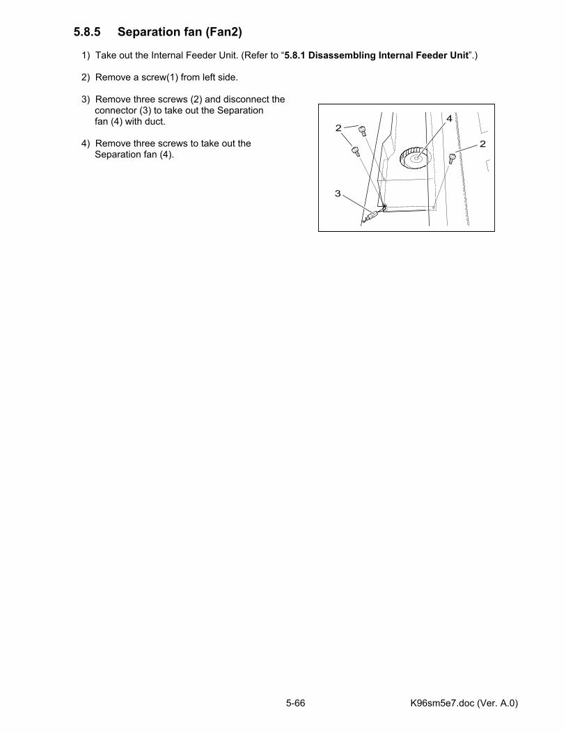
K96sm5e7.doc (Ver. A.0) 5-66
5.8.5 Separation fan (Fan2) 1) Take out the Internal Feeder Unit. (Refer to “5.8.1 Disassembling Internal Feeder Unit”.) 2) Remove a screw(1) from left side. 3) Remove three screws (2) and disconnect the connector (3) to take out the Separation fan (4) with duct. 4) Remove three screws to take out the Separation fan (4).
2
2
3
4
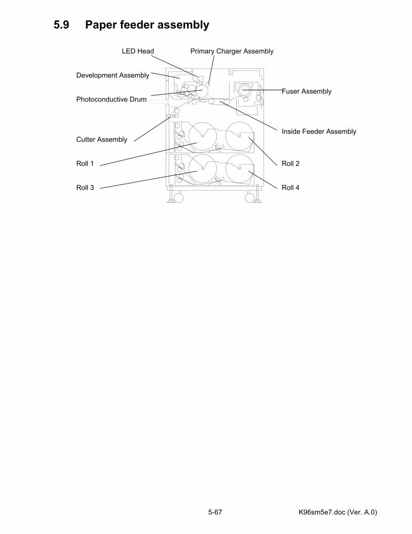
K96sm5e7.doc (Ver. A.0) 5-67
5.9 Paper feeder assembly LED Head Primary Charger Assembly
Development Assembly
Fuser Assembly Photoconductive Drum
Inside Feeder Assembly Cutter Assembly
Roll 1 Roll 2 Roll 3 Roll 4
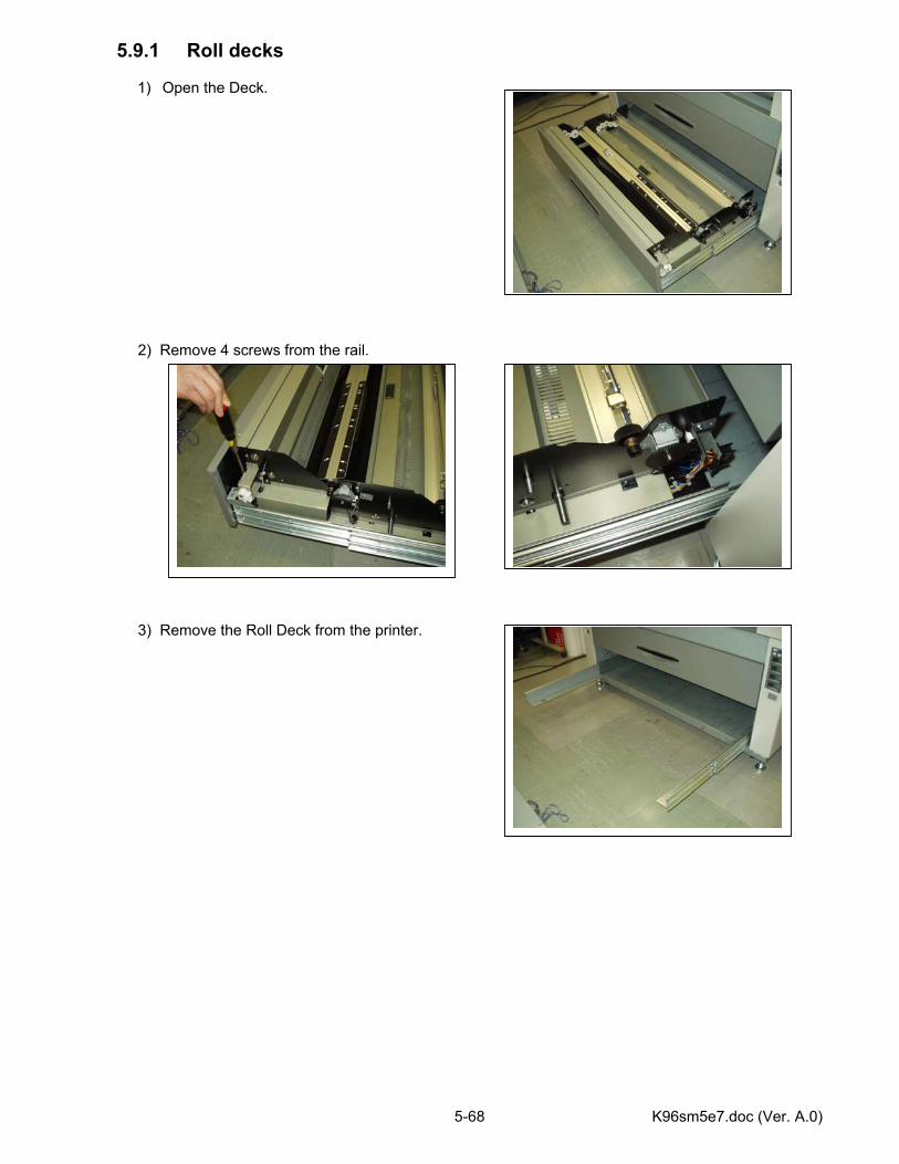
K96sm5e7.doc (Ver. A.0) 5-68
5.9.1 Roll decks
1) Open the Deck. 2) Remove 4 screws from the rail. 3) Remove the Roll Deck from the printer.
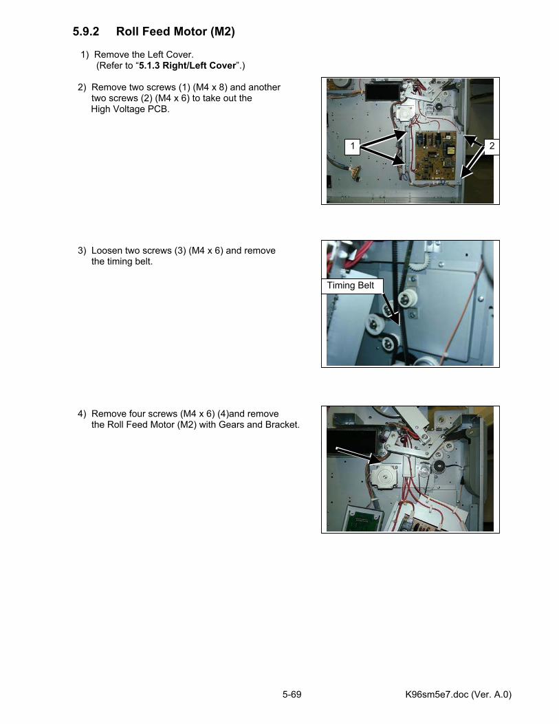
K96sm5e7.doc (Ver. A.0) 5-69
5.9.2 Roll Feed Motor (M2) 1) Remove the Left Cover. (Refer to “5.1.3 Right/Left Cover”.) 2) Remove two screws (1) (M4 x 8) and another
two screws (2) (M4 x 6) to take out the High Voltage PCB. 3) Loosen two screws (3) (M4 x 6) and remove
the timing belt.
4) Remove four screws (M4 x 6) (4)and remove
the Roll Feed Motor (M2) with Gears and Bracket.
1 2
3
Timing Belt
4
4
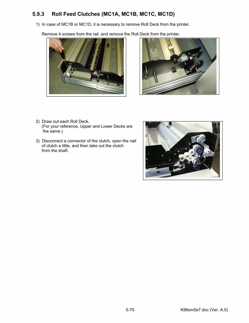
K96sm5e7.doc (Ver. A.0) 5-70
5.9.3 Roll Feed Clutches (MC1A, MC1B, MC1C, MC1D) 1) In case of MC1B or MC1D, it is necessary to remove Roll Deck from the printer. Remove 4 screws from the rail, and remove the Roll Deck from the printer. 2) Draw out each Roll Deck. (For your reference, Upper and Lower Decks are the same.) 3) Disconnect a connector of the clutch, open the nail of clutch a little, and then take out the clutch from the shaft.
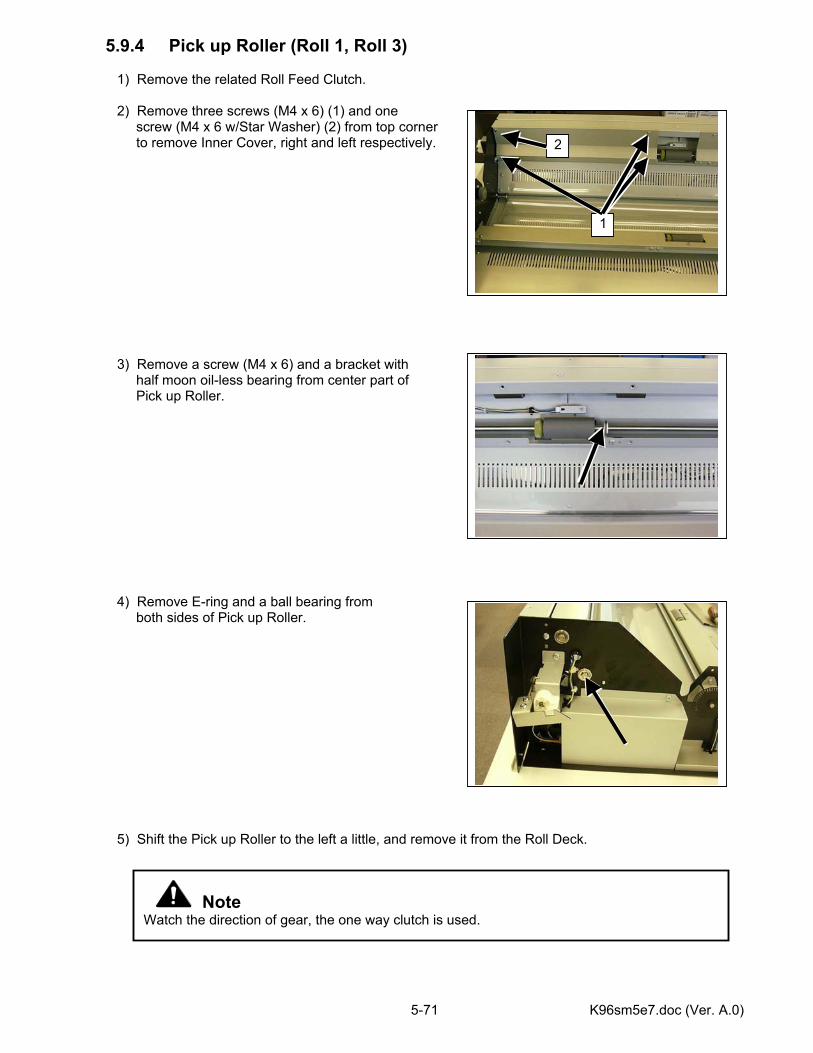
K96sm5e7.doc (Ver. A.0) 5-71
5.9.4 Pick up Roller (Roll 1, Roll 3) 1) Remove the related Roll Feed Clutch. 2) Remove three screws (M4 x 6) (1) and one screw (M4 x 6 w/Star Washer) (2) from top corner to remove Inner Cover, right and left respectively.
3) Remove a screw (M4 x 6) and a bracket with half moon oil-less bearing from center part of Pick up Roller.
4) Remove E-ring and a ball bearing from both sides of Pick up Roller.
5) Shift the Pick up Roller to the left a little, and remove it from the Roll Deck.
Note Watch the direction of gear, the one way clutch is used.
1
2
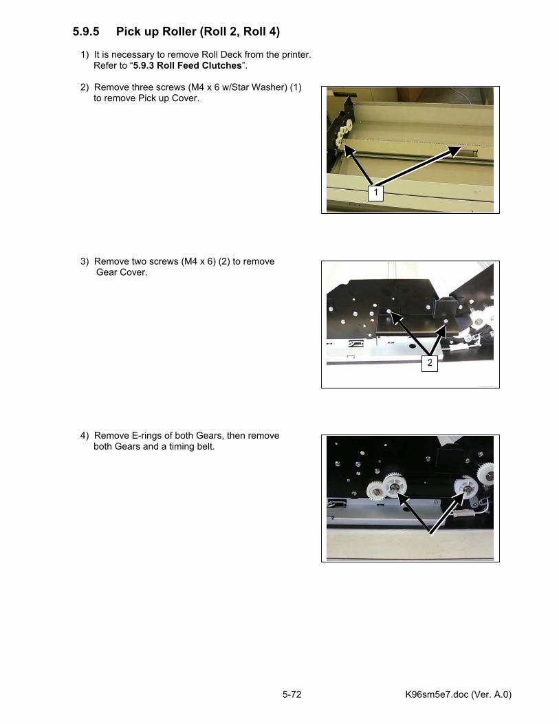
K96sm5e7.doc (Ver. A.0) 5-72
5.9.5 Pick up Roller (Roll 2, Roll 4) 1) It is necessary to remove Roll Deck from the printer. Refer to “5.9.3 Roll Feed Clutches”. 2) Remove three screws (M4 x 6 w/Star Washer) (1) to remove Pick up Cover.
3) Remove two screws (M4 x 6) (2) to remove
Gear Cover.
4) Remove E-rings of both Gears, then remove both Gears and a timing belt.
1
2
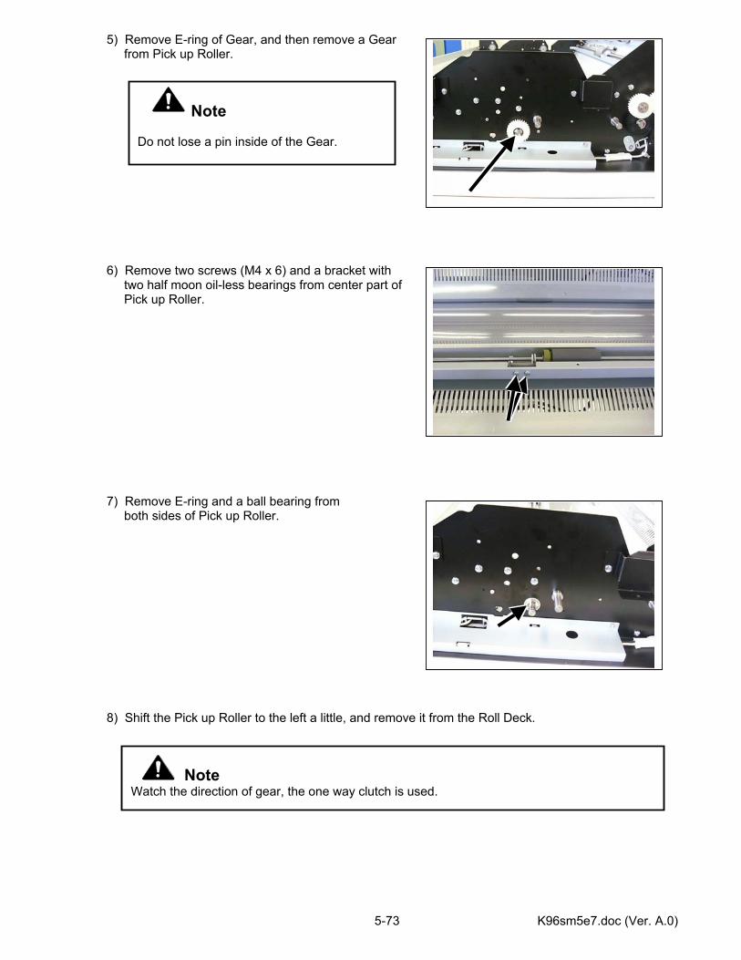
K96sm5e7.doc (Ver. A.0) 5-73
5) Remove E-ring of Gear, and then remove a Gear from Pick up Roller.
6) Remove two screws (M4 x 6) and a bracket with two half moon oil-less bearings from center part of Pick up Roller.
7) Remove E-ring and a ball bearing from both sides of Pick up Roller.
8) Shift the Pick up Roller to the left a little, and remove it from the Roll Deck.
Note Watch the direction of gear, the one way clutch is used.
Note Do not lose a pin inside of the Gear.
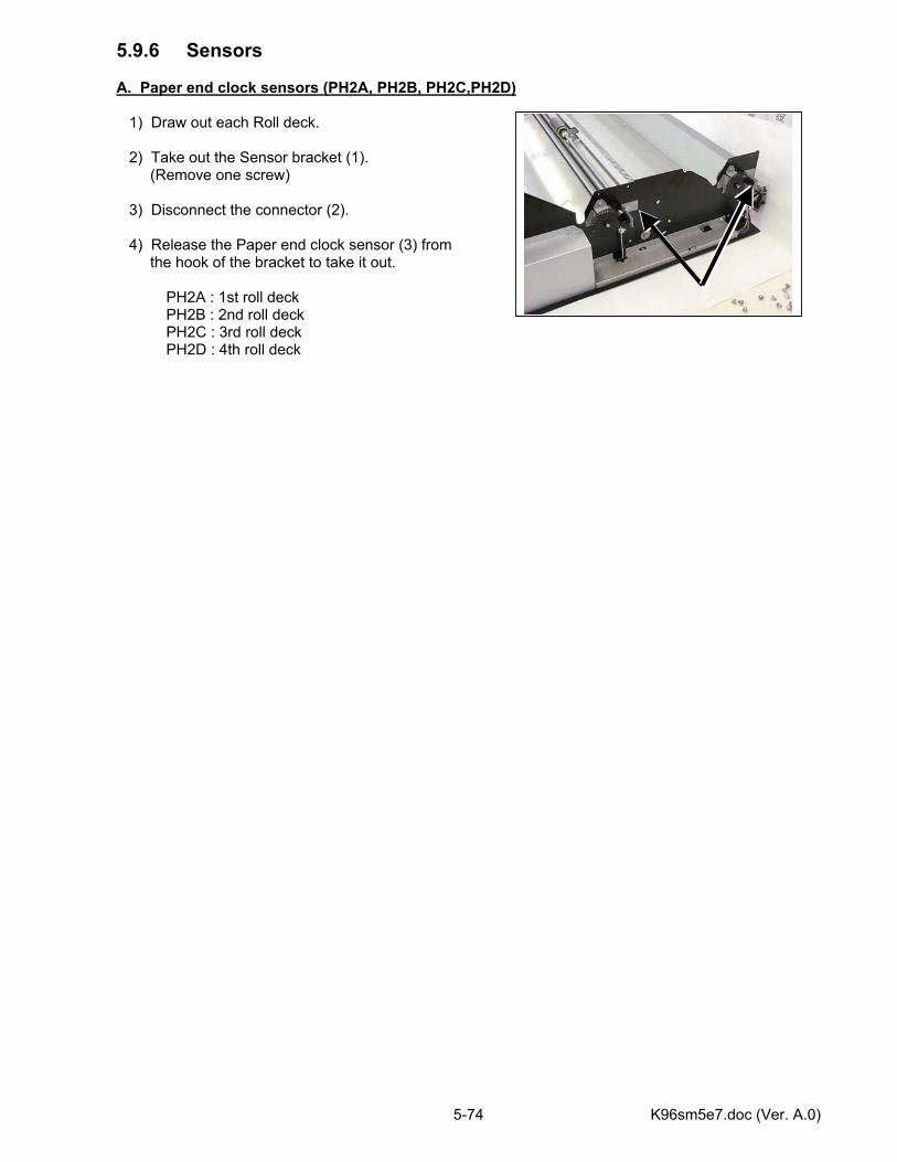
K96sm5e7.doc (Ver. A.0) 5-74
5.9.6 Sensors A. Paper end clock sensors (PH2A, PH2B, PH2C,PH2D) 1) Draw out each Roll deck. 2) Take out the Sensor bracket (1). (Remove one screw) 3) Disconnect the connector (2). 4) Release the Paper end clock sensor (3) from the hook of the bracket to take it out. PH2A : 1st roll deck PH2B : 2nd roll deck PH2C : 3rd roll deck PH2D : 4th roll deck
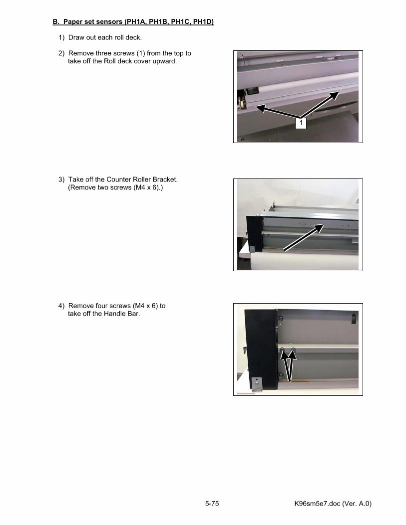
K96sm5e7.doc (Ver. A.0) 5-75
B. Paper set sensors (PH1A, PH1B, PH1C, PH1D) 1) Draw out each roll deck. 2) Remove three screws (1) from the top to take off the Roll deck cover upward. 3) Take off the Counter Roller Bracket. (Remove two screws (M4 x 6).) 4) Remove four screws (M4 x 6) to take off the Handle Bar.
1
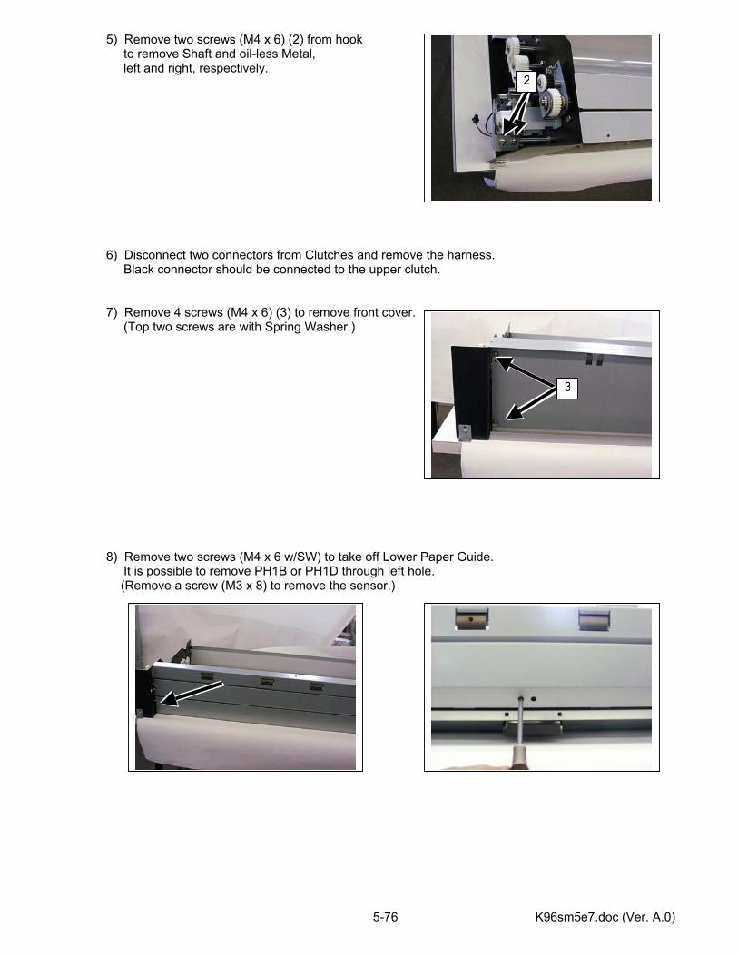
K96sm5e7.doc (Ver. A.0) 5-76
5) Remove two screws (M4 x 6) (2) from hook to remove Shaft and oil-less Metal, left and right, respectively. 6) Disconnect two connectors from Clutches and remove the harness. Black connector should be connected to the upper clutch. 7) Remove 4 screws (M4 x 6) (3) to remove front cover. (Top two screws are with Spring Washer.) 8) Remove two screws (M4 x 6 w/SW) to take off Lower Paper Guide. It is possible to remove PH1B or PH1D through left hole.
(Remove a screw (M3 x 8) to remove the sensor.)
2
3
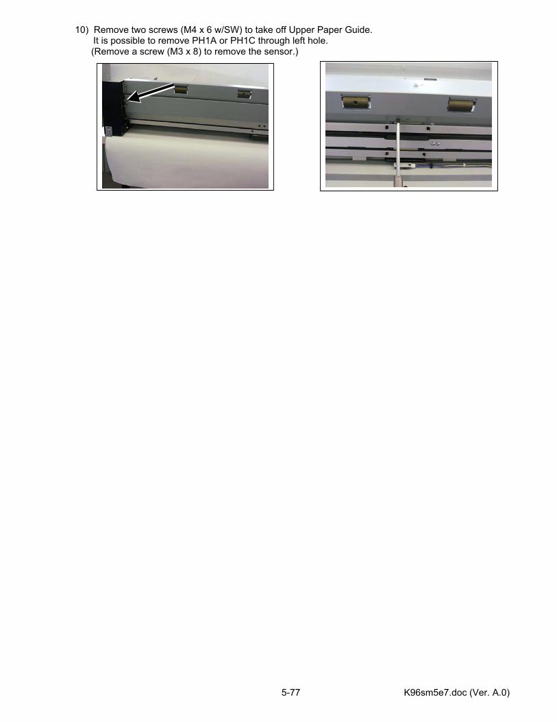
K96sm5e7.doc (Ver. A.0) 5-77
10) Remove two screws (M4 x 6 w/SW) to take off Upper Paper Guide. It is possible to remove PH1A or PH1C through left hole.
(Remove a screw (M3 x 8) to remove the sensor.)
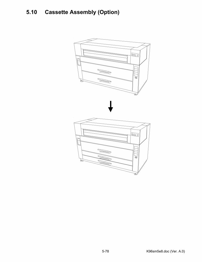
K96sm5e8.doc (Ver. A.0) 5-78
5.10 Cassette Assembly (Option)
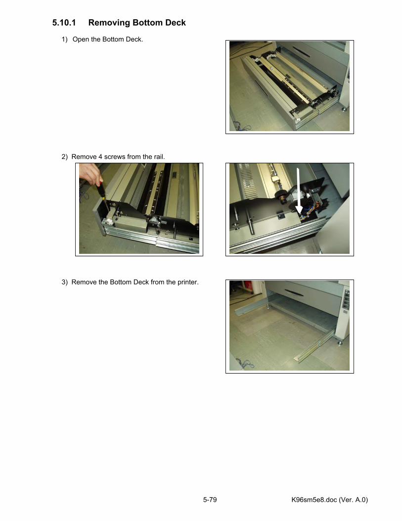
K96sm5e8.doc (Ver. A.0) 5-79
5.10.1 Removing Bottom Deck
1) Open the Bottom Deck. 2) Remove 4 screws from the rail. 3) Remove the Bottom Deck from the printer.
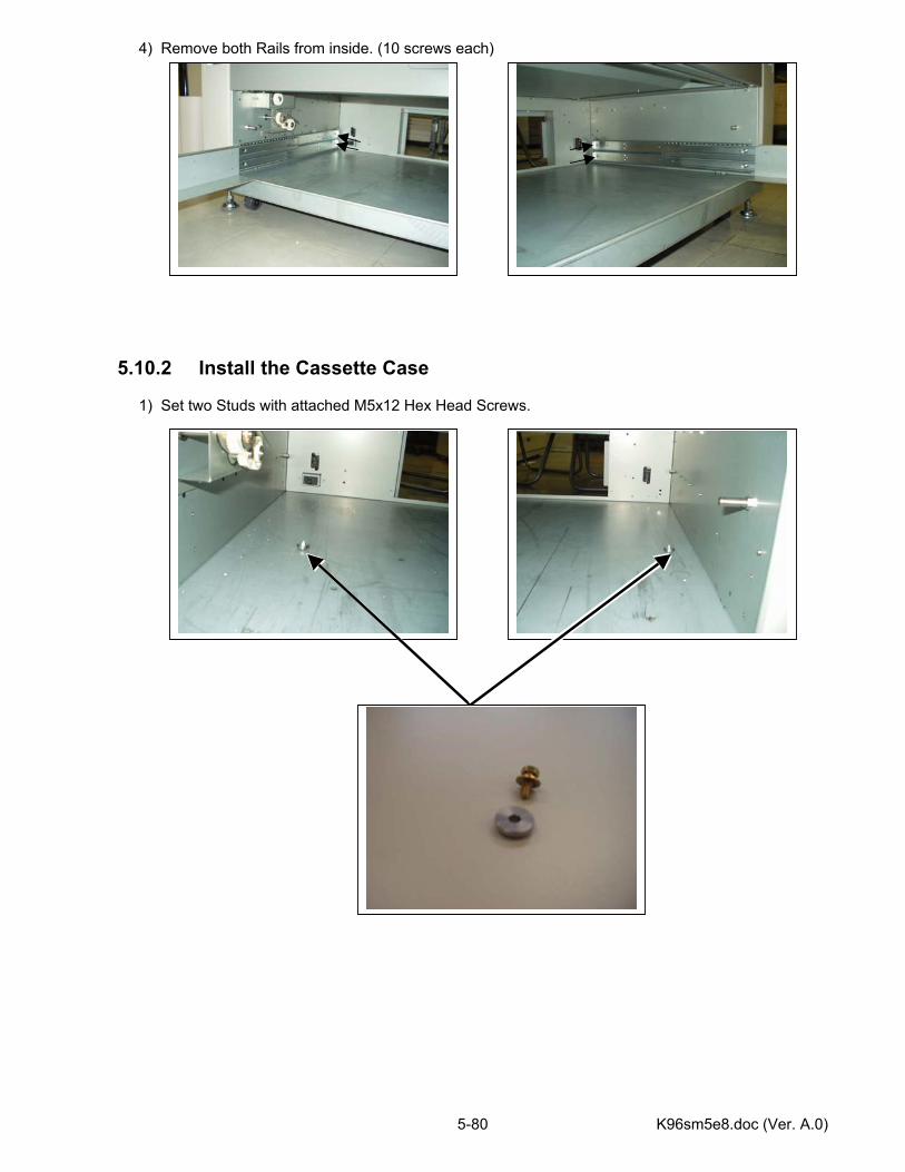
K96sm5e8.doc (Ver. A.0) 5-80
4) Remove both Rails from inside. (10 screws each) 5.10.2 Install the Cassette Case 1) Set two Studs with attached M5x12 Hex Head Screws.
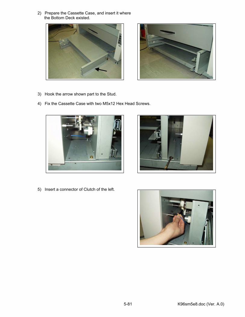
K96sm5e8.doc (Ver. A.0) 5-81
2) Prepare the Cassette Case, and insert it where the Bottom Deck existed.
3) Hook the arrow shown part to the Stud. 4) Fix the Cassette Case with two M5x12 Hex Head Screws. 5) Insert a connector of Clutch of the left.

K96sm5e8.doc (Ver. A.0) 5-82
6) Remove the Rear Cover from the Printer. 7) Connect a connector and fix the lead wire with two Wire Clumps. 5.10.3 Install the Cassette 1) Pull the Rails of the Cassette, and put the Lower Cassette. 2) Fix the Cassette with four screws. 3) Put the Upper Cassette with the same manner. 4) Put back the Rear Cover with 6 screws.
Rear Cover
Wire Clump Connector
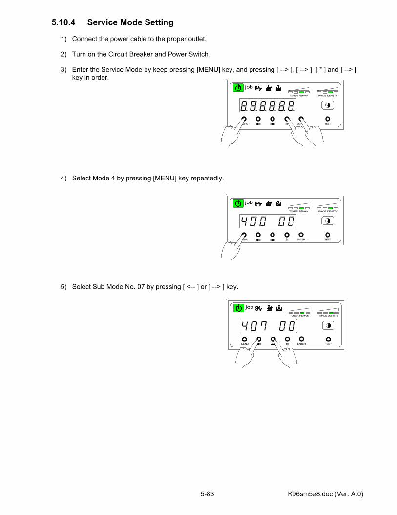
K96sm5e8.doc (Ver. A.0) 5-83
5.10.4 Service Mode Setting
1) Connect the power cable to the proper outlet. 2) Turn on the Circuit Breaker and Power Switch.
3) Enter the Service Mode by keep pressing [MENU] key, and pressing [ --> ], [ --> ], [ * ] and [ --> ]
key in order.
4) Select Mode 4 by pressing [MENU] key repeatedly.
5) Select Sub Mode No. 07 by pressing [ <-- ] or [ --> ] key.
MENU ENTER TEST
TONER REMAIN IMAGE DENSITY
job
*
MENU ENTER TEST
TONER REMAIN IMAGE DENSITY
job
*
MENU ENTER TEST
TONER REMAIN IMAGE DENSITY
job
*
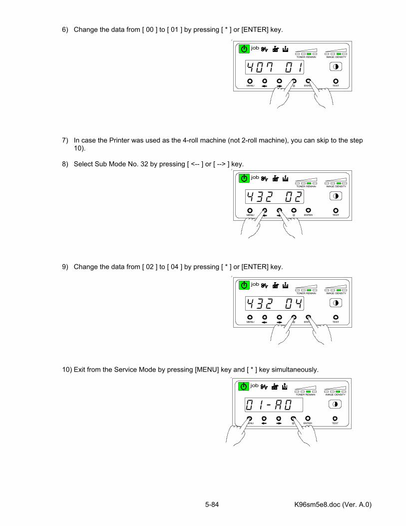
K96sm5e8.doc (Ver. A.0) 5-84
6) Change the data from [ 00 ] to [ 01 ] by pressing [ * ] or [ENTER] key.
7) In case the Printer was used as the 4-roll machine (not 2-roll machine), you can skip to the step 10).
8) Select Sub Mode No. 32 by pressing [ <-- ] or [ --> ] key.
9) Change the data from [ 02 ] to [ 04 ] by pressing [ * ] or [ENTER] key.
10) Exit from the Service Mode by pressing [MENU] key and [ * ] key simultaneously.
MENU ENTER TEST
TONER REMAIN IMAGE DENSITY
job
*
MENU ENTER TEST
TONER REMAIN IMAGE DENSITY
job
*
MENU ENTER TEST
TONER REMAIN IMAGE DENSITY
job
*
MENU ENTER TEST
TONER REMAIN IMAGE DENSITY
job
*
K96sm6e1-1.doc (Ver. A.0)
Chapter 6
Maintenance Page 6.1 Maintenance 6- 1 6.2 Fuse Replacement 6- 3
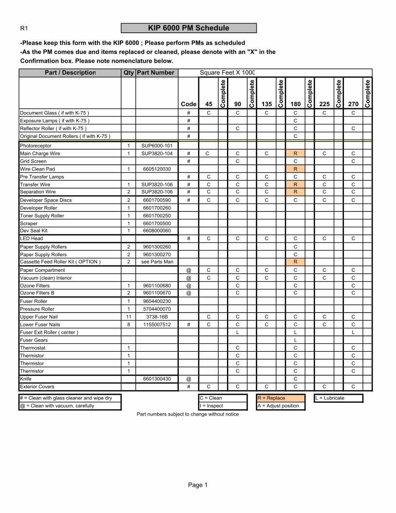
R1 KIP 6000 PM Schedule
-Please keep this form with the KIP 6000 ; Please perform PMs as scheduled-As the PM comes due and items replaced or cleaned, please denote with an "X" in the Confirmation box. Please note nomenclature below.
Part / Description Qty Part Number Square Feet X 1000
Code 45 Com
plet
e
90 Com
plet
e
135 Com
plet
e
180 Com
plet
e
225 Com
plet
e
270 Com
plet
e
Document Glass ( if with K-75 ) # C C C C C CExposure Lamps ( if with K-75 ) # CReflector Roller ( if with K-75 ) # C C COriginal Document Rollers ( if with K-75 ) # C
Photoreceptor 1 SUP6000-101 Main Charge Wire 1 SUP3820-104 # C C C R C CGrid Screen # C C CWire Clean Pad 1 6605120030 RPre Transfer Lamps # C C C C C CTransfer Wire 1 SUP3820-106 # C C C R C CSeparation Wire 2 SUP3820-106 # C C C R C CDeveloper Space Discs 2 6601700590 # C C C C C CDeveloper Roller 1 6601700260Toner Supply Roller 1 6601700250Scraper 1 6601700500Dev Seal Kit 1 6608000060LED Head # C C C C C CPaper Supply Rollers 2 9601300260 CPaper Supply Rollers 2 9601300270 CCassette Feed Roller Kit ( OPTION ) 2 see Parts Man RPaper Compartment @ C C C C C CVacuum (clean) Interior @ C C C C C COzone Filters 1 9601100680 @ C C COzone Filters B 2 9601100670 @ C C CFuser Roller 1 9604400230Pressure Roller 1 5704400070Upper Fuser Nail 11 3738-16B C C C C C CLower Fuser Nails 8 1155007512 # C C C C C CFuser Exit Roller ( center ) L L LFuser Gears LThermostat 1 C C CThermistor 1 C C CThermistor 1 C C CThermistor 1 C C CKnife 6601300430 @ CExterior Covers # C C C C C C
# = Clean with glass cleaner and wipe dry C = Clean R = Replace L = Lubricate @ = Clean with vacuum, carefully I = Inspect A = Adjust position
Part numbers subject to change without notice
Page 1
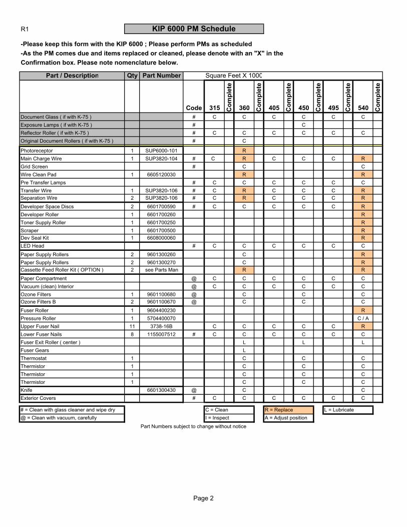
R1 KIP 6000 PM Schedule
-Please keep this form with the KIP 6000 ; Please perform PMs as scheduled-As the PM comes due and items replaced or cleaned, please denote with an "X" in the Confirmation box. Please note nomenclature below.
Part / Description Qty Part Number Square Feet X 1000
Code 315 Com
plet
e
360 Com
plet
e
405 Com
plet
e
450 Com
plet
e
495 Com
plet
e
540 Com
plet
e
Document Glass ( if with K-75 ) # C C C C C CExposure Lamps ( if with K-75 ) # CReflector Roller ( if with K-75 ) # C C C C C COriginal Document Rollers ( if with K-75 ) # C
Photoreceptor 1 SUP6000-101 R Main Charge Wire 1 SUP3820-104 # C R C C C RGrid Screen # C CWire Clean Pad 1 6605120030 R RPre Transfer Lamps # C C C C C CTransfer Wire 1 SUP3820-106 # C R C C C RSeparation Wire 2 SUP3820-106 # C R C C C RDeveloper Space Discs 2 6601700590 # C C C C C RDeveloper Roller 1 6601700260 RToner Supply Roller 1 6601700250 RScraper 1 6601700500 RDev Seal Kit 1 6608000060 RLED Head # C C C C C CPaper Supply Rollers 2 9601300260 C RPaper Supply Rollers 2 9601300270 C RCassette Feed Roller Kit ( OPTION ) 2 see Parts Man R RPaper Compartment @ C C C C C CVacuum (clean) Interior @ C C C C C COzone Filters 1 9601100680 @ C C COzone Filters B 2 9601100670 @ C C CFuser Roller 1 9604400230 RPressure Roller 1 5704400070 C / AUpper Fuser Nail 11 3738-16B C C C C C RLower Fuser Nails 8 1155007512 # C C C C C CFuser Exit Roller ( center ) L L LFuser Gears L Thermostat 1 C C CThermistor 1 C C CThermistor 1 C C CThermistor 1 C C CKnife 6601300430 @ C CExterior Covers # C C C C C C
# = Clean with glass cleaner and wipe dry C = Clean R = Replace L = Lubricate @ = Clean with vacuum, carefully I = Inspect A = Adjust position
Part Numbers subject to change without notice
Page 2
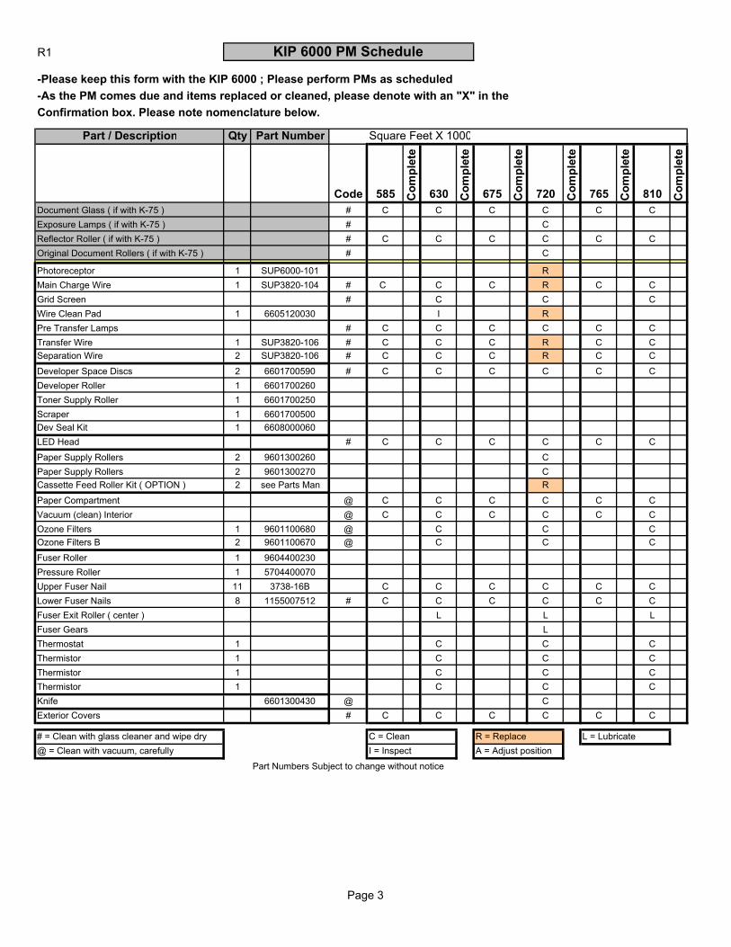
R1 KIP 6000 PM Schedule
-Please keep this form with the KIP 6000 ; Please perform PMs as scheduled-As the PM comes due and items replaced or cleaned, please denote with an "X" in the Confirmation box. Please note nomenclature below.
Part / Description Qty Part Number Square Feet X 1000
Code 585 Com
plet
e
630 Com
plet
e
675 Com
plet
e
720 Com
plet
e
765 Com
plet
e
810 Com
plet
e
Document Glass ( if with K-75 ) # C C C C C CExposure Lamps ( if with K-75 ) # CReflector Roller ( if with K-75 ) # C C C C C COriginal Document Rollers ( if with K-75 ) # C
Photoreceptor 1 SUP6000-101 RMain Charge Wire 1 SUP3820-104 # C C C R C CGrid Screen # C C CWire Clean Pad 1 6605120030 I RPre Transfer Lamps # C C C C C CTransfer Wire 1 SUP3820-106 # C C C R C CSeparation Wire 2 SUP3820-106 # C C C R C CDeveloper Space Discs 2 6601700590 # C C C C C CDeveloper Roller 1 6601700260Toner Supply Roller 1 6601700250Scraper 1 6601700500Dev Seal Kit 1 6608000060LED Head # C C C C C CPaper Supply Rollers 2 9601300260 CPaper Supply Rollers 2 9601300270 CCassette Feed Roller Kit ( OPTION ) 2 see Parts Man RPaper Compartment @ C C C C C CVacuum (clean) Interior @ C C C C C COzone Filters 1 9601100680 @ C C COzone Filters B 2 9601100670 @ C C CFuser Roller 1 9604400230Pressure Roller 1 5704400070Upper Fuser Nail 11 3738-16B C C C C C CLower Fuser Nails 8 1155007512 # C C C C C CFuser Exit Roller ( center ) L L LFuser Gears LThermostat 1 C C CThermistor 1 C C CThermistor 1 C C CThermistor 1 C C CKnife 6601300430 @ CExterior Covers # C C C C C C
# = Clean with glass cleaner and wipe dry C = Clean R = Replace L = Lubricate @ = Clean with vacuum, carefully I = Inspect A = Adjust position
Part Numbers Subject to change without notice
Page 3
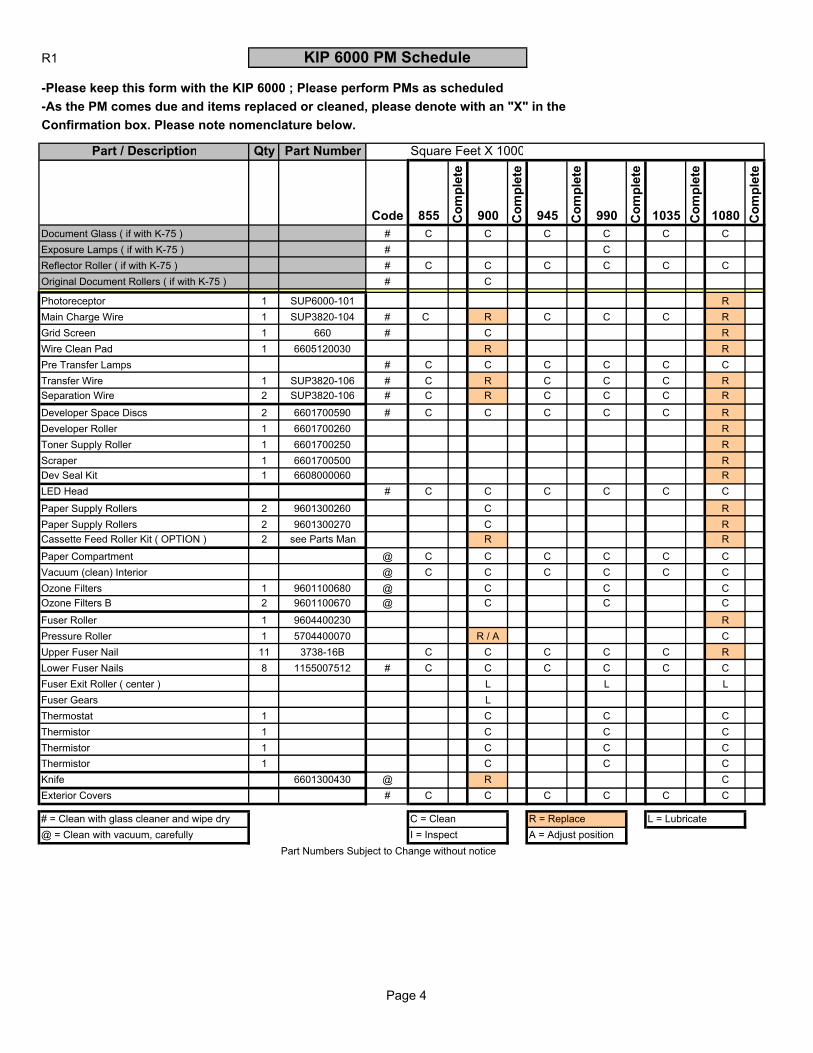
R1 KIP 6000 PM Schedule
-Please keep this form with the KIP 6000 ; Please perform PMs as scheduled-As the PM comes due and items replaced or cleaned, please denote with an "X" in the Confirmation box. Please note nomenclature below.
Part / Description Qty Part Number Square Feet X 1000
Code 855 Com
plet
e
900 Com
plet
e
945 Com
plet
e
990 Com
plet
e
1035 Com
plet
e
1080 Com
plet
e
Document Glass ( if with K-75 ) # C C C C C CExposure Lamps ( if with K-75 ) # CReflector Roller ( if with K-75 ) # C C C C C COriginal Document Rollers ( if with K-75 ) # C
Photoreceptor 1 SUP6000-101 RMain Charge Wire 1 SUP3820-104 # C R C C C RGrid Screen 1 660 # C RWire Clean Pad 1 6605120030 R RPre Transfer Lamps # C C C C C CTransfer Wire 1 SUP3820-106 # C R C C C RSeparation Wire 2 SUP3820-106 # C R C C C RDeveloper Space Discs 2 6601700590 # C C C C C RDeveloper Roller 1 6601700260 RToner Supply Roller 1 6601700250 RScraper 1 6601700500 RDev Seal Kit 1 6608000060 RLED Head # C C C C C CPaper Supply Rollers 2 9601300260 C RPaper Supply Rollers 2 9601300270 C RCassette Feed Roller Kit ( OPTION ) 2 see Parts Man R RPaper Compartment @ C C C C C CVacuum (clean) Interior @ C C C C C COzone Filters 1 9601100680 @ C C COzone Filters B 2 9601100670 @ C C CFuser Roller 1 9604400230 RPressure Roller 1 5704400070 R / A CUpper Fuser Nail 11 3738-16B C C C C C RLower Fuser Nails 8 1155007512 # C C C C C CFuser Exit Roller ( center ) L L LFuser Gears L Thermostat 1 C C CThermistor 1 C C CThermistor 1 C C CThermistor 1 C C CKnife 6601300430 @ R CExterior Covers # C C C C C C
# = Clean with glass cleaner and wipe dry C = Clean R = Replace L = Lubricate @ = Clean with vacuum, carefully I = Inspect A = Adjust position
Part Numbers Subject to Change without notice
Page 4
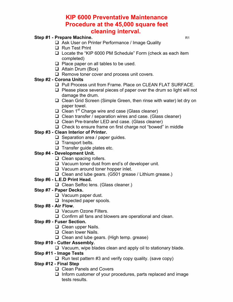
KIP 6000 Preventative Maintenance Procedure at the 45,000 square feet
cleaning interval. Step #1 - Prepare Machine. R1
Ask User on Printer Performance / Image Quality Run Test Print Locate the “KIP 6000 PM Schedule” Form (check as each item
completed) Place paper on all tables to be used. Attain Drum (Box) Remove toner cover and process unit covers.
Step #2 - Corona Units Pull Process unit from Frame. Place on CLEAN FLAT SURFACE. Please place several pieces of paper over the drum so light will not
damage the drum. Clean Grid Screen (Simple Green, then rinse with water) let dry on
paper towel. Clean 1st Charge wire and case (Glass cleaner) Clean transfer / separation wires and case. (Glass cleaner) Clean Pre-transfer LED and case. (Glass cleaner) Check to ensure frame on first charge not “bowed” in middle
Step #3 - Clean Interior of Printer. Separation area / paper guides. Transport belts. Transfer guide plates etc.
Step #4 - Development Unit. Clean spacing rollers. Vacuum toner dust from end’s of developer unit. Vacuum around toner hopper inlet. Clean and lube gears. (G501 grease / Lithium grease.)
Step #6 - L.E.D Print Head. Clean Selfoc lens. (Glass cleaner.)
Step #7 - Paper Decks. Vacuum paper dust. Inspected paper spools.
Step #8 - Air Flow. Vacuum Ozone Filters. Confirm all fans and blowers are operational and clean.
Step #9 - Fuser Section. Clean upper Nails. Clean lower Nails. Clean and lube gears. (High temp. grease)
Step #10 - Cutter Assembly. Vacuum, wipe blades clean and apply oil to stationary blade.
Step #11 - Image Tests Run test pattern #3 and verify copy quality. (save copy)
Step #12 - Final Step Clean Panels and Covers Inform customer of your procedures, parts replaced and image
tests results.
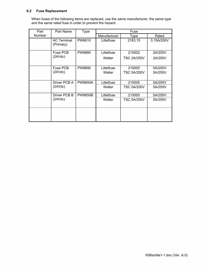
K96sm6e1-1.doc (Ver. A.0)
6.2 Fuse Replacement When fuses of the following items are replaced, use the same manufacturer, the same type and the same rated fuse in order to prevent fire hazard.
Fuse Part Number
Part Name Type Manufacturer Type Rated
AC Terminal (Primary)
PW6610 Littelfuse 2183.15 3.15A/250V
Littelfuse 215002 2A/250V Fuse PCB (24Vdc)
PW9680 Walter TSC 2A/250V 2A/250V
Littelfuse 215005 5A/250V Fuse PCB (24Vdc)
PW9690 Walter TSC 5A/250V 5A/250V
Littelfuse 215005 5A/250V Driver PCB A (24Vdc)
PW9650A Walter TSC 5A/250V 5A/250V
Littelfuse 215005 5A/250V Driver PCB B (24Vdc)
PW9650B Walter TSC 5A/250V 5A/250V
K96sm7e1.doc (Ver. A.0)
Chapter 7
Troubleshooting Page 7.1 Error Code List 7- 1 7.1.1 Operator Call Errors 7- 1 7.1.2 Service Call Errors 7- 3 7.1.3 Optional Instrument Errors 7- 3 7.2 Troubleshooting against Errors 7- 4 7.2.1 Countermeasures against Operator Call Errors 7- 4 (1) “J-01” 1st Roll Jam 7- 4 (2) “J-02” 2nd Roll Jam 7- 5 (3) “J-03” 3rd Roll Jam 7- 6 (4) “J-04” 4th Roll Jam 7- 7 (5) “J-05” Bypass Jam 7- 8 (6) “J-10” Flapper Area Jam 7- 9 (7) “J-11” Inner Transport Area Jam 7-10 (8) “J-12” Separation Area Jam 7-11 (9) “J-13” Exit Area Jam (Delay) 7-12 (10) “J-14” Exit Area Jam (Stay) 7-13 (11) “U-01” Upper Roll Deck Open Error 7-14 (12) “U-02” Lower Roll Deck Open Error 7-15 (13) “U-02” Upper Cassette Deck Open Error (Option) 7-16 (14) “U-03” Lower Cassette Deck Open Error (Option) 7-17 (15) “U-05” Process Unit / Toner Cover Open Error 7-18 (16) “U-06” Heater Door Open Error 7-18 (17) Toner Low 7-19 (18) Roll Empty 7-20 7.2.2 Countermeasures against Service Call Errors 7-21 (1) “E-01” Fuser Temperature Rising Error 7-21 (2) “E-02” Fuser Over Temperature Error 7-23 (3) “E-04” Developer Error 7-25 (4) “E-06” Counter Error 7-25 (5) “E-07” Cutter Error 7-26 (6) “E-14” Fuser Motor Error 7-27 (7) “E-16” Wire Cleaning Error 7-28 (8) “E-21” Fuser Thermostat Error 7-29 (9) “E-50” Cassette Error (Option) 7-30 7.2.3 Countermeasures against Optional Instrument Errors 7-31 (1) “J-21” Optional Instrument Jam (Delay) 7-31 (2) “J-22” Optional Instrument Jam (Stay) 7-31 (3) “E-40” Folder Error (Option) 7-32 (4) “E-41” Key Card Error (Option) 7-32
K96sm7e1.doc (Ver. A.0)
7.3 Troubleshooting against Image Quality Defect 7-33 7.3.1 Basic Image Adjustment 7-33 7.3.2 Troubles 7-34 (1) Too light image (Only the halftone image) 7-34
(2) Too light image (Halftone and solid black) 7-35 (3) Extremely light image (The whole image) 7-36 (4) Different copy density 7-37 (5) Totally appeared foggy image 7-38 (6) Vertically blurred or foggy black wide line 7-38 (7) Vertical Clear Black Narrow Line 7-39 (8) Vertical White Line 7-39 (9) Void of image 7-40 (10) Dirt on the back of the copy 7-40 (11) Defective fusing 7-41 (12) Incorrect Image Placement, No Leading Edge 7-41 (13) Jitter 7-42 (14) Less sharpened image 7-42 (15) Uneven image vertically 7-42 (16) Totally white (No image) 7-43 (17) Totally black 7-43

K96sm7e2.doc (Ver. A.0) 7-1
7.1 Error Code List 7.1.1 Operator Call Errors Following errors are Operator Call Errors which can be fixed by an operator.
Error Code Name of the error Error condition J - 01 1st Roll Jam 1. The Roll Paper Set Sensor Signal (RPSET1) does not
change from H to L within a specified time since the machine has started feeding. 2. The Roll Paper Set Sensor Signal (RPSET1) does not change from L to H within a specified time since the machine has started rewinding.
J - 02 2nd Roll Jam 1. The Roll Paper Set Sensor Signal (RPSET2) does not change from H to L within a specified time since the machine has started feeding. 2. The Roll Paper Set Sensor Signal (RPSET2) does not change from L to H within a specified time since the machine has started rewinding.
J - 03 3rd Roll Jam 1. The Roll Paper Set Sensor Signal (RPSET3) does not change from H to L within a specified time since the machine has started feeding. 2. The Roll Paper Set Sensor Signal (RPSET3) does not change from L to H within a specified time since the machine has started rewinding. 3. When Cassette is used, Cassette Paper Feeding
Check Signal (CS1_CHK1, CS1_CHK2) do not change from H to L within a specified time.
J - 04 4th Roll Jam 1. The Roll Paper Set Sensor Signal (RPSET4) does not change from H to L within a specified time since the machine has started feeding. 2. The Roll Paper Set Sensor Signal (RPSET4) does not change from L to H within a specified time since the machine has started rewinding. 3. When Cassette is used, Cassette Paper Feeding
Check Signal (CS2_CHK1, CS2_CHK2) do not change from H to L within a specified time.
J - 05 Bypass Jam 1. The Paper Gate Sensor Signal (P_GATE) does not change from H to L within a specified time since the paper has started from the specified position. 2. The Paper Gate Sensor Signal (P_GATE) changes from L to H within a specified time since the paper has
started, because the cut sheet paper was shorter than specified.
J - 10 Flapper Area Jam 1. Either Flapper Sensor Signal (P_FLAP) or Paper Reset Signal (RPSET) does not change from H
to L within a specified time since the machine has started to feed the roll paper from the specified position.
2. Either Flapper Sensor Signal (P_FLAP) or Paper Reset Signal (RPSET) does not change from L
to H within a specified time since the machine has started to rewind the roll paper.
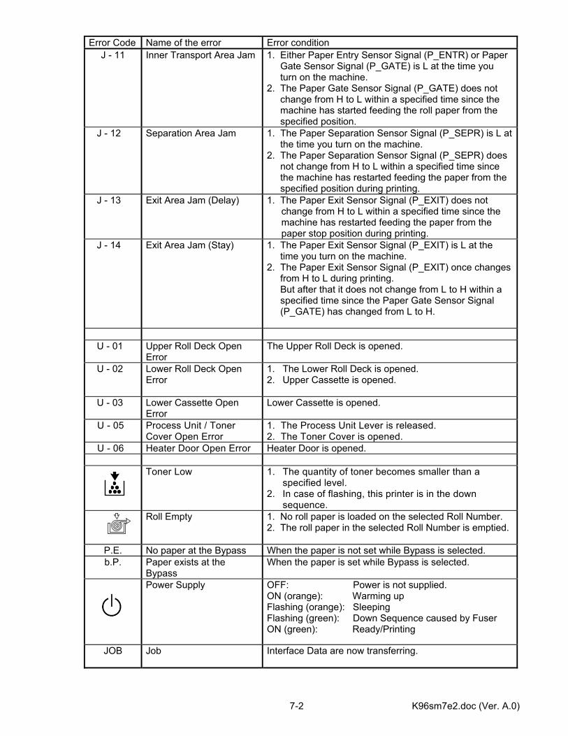
K96sm7e2.doc (Ver. A.0) 7-2
Error Code Name of the error Error condition
J - 11 Inner Transport Area Jam 1. Either Paper Entry Sensor Signal (P_ENTR) or Paper Gate Sensor Signal (P_GATE) is L at the time you turn on the machine. 2. The Paper Gate Sensor Signal (P_GATE) does not change from H to L within a specified time since the machine has started feeding the roll paper from the specified position.
J - 12
Separation Area Jam 1. The Paper Separation Sensor Signal (P_SEPR) is L at the time you turn on the machine. 2. The Paper Separation Sensor Signal (P_SEPR) does not change from H to L within a specified time since the machine has restarted feeding the paper from the specified position during printing.
J - 13
Exit Area Jam (Delay) 1. The Paper Exit Sensor Signal (P_EXIT) does not change from H to L within a specified time since the machine has restarted feeding the paper from the paper stop position during printing.
J - 14
Exit Area Jam (Stay) 1. The Paper Exit Sensor Signal (P_EXIT) is L at the time you turn on the machine. 2. The Paper Exit Sensor Signal (P_EXIT) once changes from H to L during printing. But after that it does not change from L to H within a specified time since the Paper Gate Sensor Signal (P_GATE) has changed from L to H.
U - 01 Upper Roll Deck Open
Error The Upper Roll Deck is opened.
U - 02 Lower Roll Deck Open Error
1. The Lower Roll Deck is opened. 2. Upper Cassette is opened.
U - 03 Lower Cassette Open Error
Lower Cassette is opened.
U - 05 Process Unit / Toner Cover Open Error
1. The Process Unit Lever is released. 2. The Toner Cover is opened.
U - 06 Heater Door Open Error Heater Door is opened.
Toner Low 1. The quantity of toner becomes smaller than a specified level.
2. In case of flashing, this printer is in the down sequence.
Roll Empty 1. No roll paper is loaded on the selected Roll Number. 2. The roll paper in the selected Roll Number is emptied.
P.E. No paper at the Bypass When the paper is not set while Bypass is selected. b.P. Paper exists at the
Bypass When the paper is set while Bypass is selected.
Power Supply OFF: Power is not supplied. ON (orange): Warming up Flashing (orange): Sleeping Flashing (green): Down Sequence caused by Fuser ON (green): Ready/Printing
JOB
Job Interface Data are now transferring.
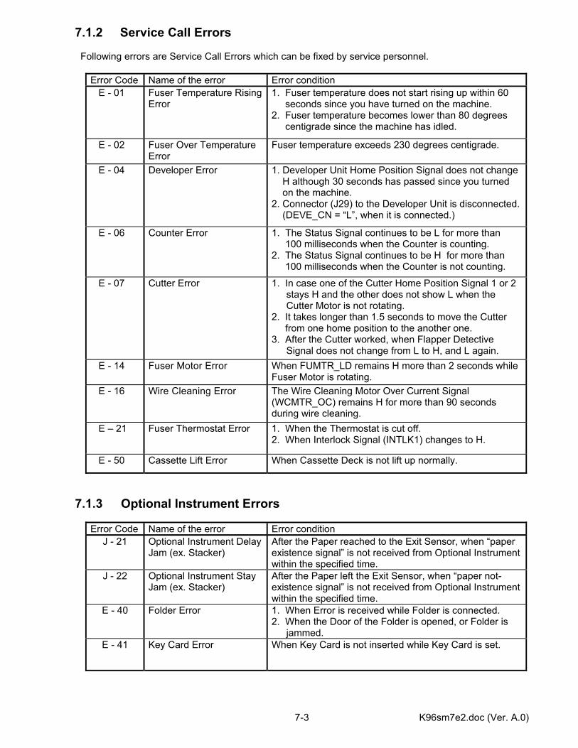
K96sm7e2.doc (Ver. A.0) 7-3
7.1.2 Service Call Errors Following errors are Service Call Errors which can be fixed by service personnel.
Error Code Name of the error Error condition E - 01 Fuser Temperature Rising
Error 1. Fuser temperature does not start rising up within 60 seconds since you have turned on the machine. 2. Fuser temperature becomes lower than 80 degrees centigrade since the machine has idled.
E - 02 Fuser Over Temperature Error
Fuser temperature exceeds 230 degrees centigrade.
E - 04 Developer Error 1. Developer Unit Home Position Signal does not change H although 30 seconds has passed since you turned on the machine. 2. Connector (J29) to the Developer Unit is disconnected. (DEVE_CN = “L”, when it is connected.)
E - 06 Counter Error 1. The Status Signal continues to be L for more than 100 milliseconds when the Counter is counting. 2. The Status Signal continues to be H for more than 100 milliseconds when the Counter is not counting.
E - 07 Cutter Error 1. In case one of the Cutter Home Position Signal 1 or 2 stays H and the other does not show L when the Cutter Motor is not rotating.
2. It takes longer than 1.5 seconds to move the Cutter from one home position to the another one. 3. After the Cutter worked, when Flapper Detective
Signal does not change from L to H, and L again. E - 14 Fuser Motor Error When FUMTR_LD remains H more than 2 seconds while
Fuser Motor is rotating. E - 16 Wire Cleaning Error The Wire Cleaning Motor Over Current Signal
(WCMTR_OC) remains H for more than 90 seconds during wire cleaning.
E – 21 Fuser Thermostat Error 1. When the Thermostat is cut off. 2. When Interlock Signal (INTLK1) changes to H.
E - 50 Cassette Lift Error When Cassette Deck is not lift up normally.
7.1.3 Optional Instrument Errors
Error Code Name of the error Error condition J - 21 Optional Instrument Delay
Jam (ex. Stacker) After the Paper reached to the Exit Sensor, when “paper existence signal” is not received from Optional Instrument within the specified time.
J - 22 Optional Instrument Stay Jam (ex. Stacker)
After the Paper left the Exit Sensor, when “paper not-existence signal” is not received from Optional Instrument within the specified time.
E - 40 Folder Error 1. When Error is received while Folder is connected. 2. When the Door of the Folder is opened, or Folder is
jammed. E - 41 Key Card Error When Key Card is not inserted while Key Card is set.
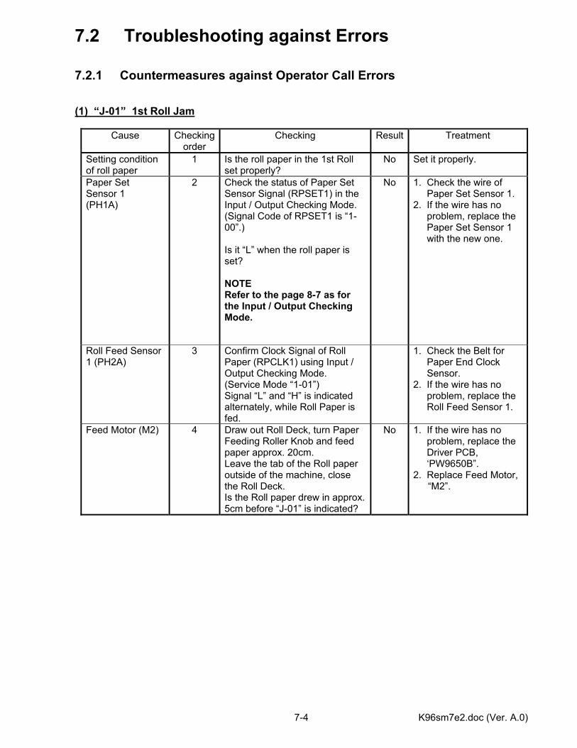
K96sm7e2.doc (Ver. A.0) 7-4
7.2 Troubleshooting against Errors 7.2.1 Countermeasures against Operator Call Errors (1) “J-01” 1st Roll Jam
Cause Checking order
Checking Result Treatment
Setting condition of roll paper
1 Is the roll paper in the 1st Roll set properly?
No Set it properly.
Paper Set Sensor 1 (PH1A)
2 Check the status of Paper Set Sensor Signal (RPSET1) in the Input / Output Checking Mode. (Signal Code of RPSET1 is “1-00”.) Is it “L” when the roll paper is set? NOTE Refer to the page 8-7 as for the Input / Output Checking Mode.
No 1. Check the wire of Paper Set Sensor 1. 2. If the wire has no problem, replace the Paper Set Sensor 1 with the new one.
Roll Feed Sensor 1 (PH2A)
3 Confirm Clock Signal of Roll Paper (RPCLK1) using Input / Output Checking Mode. (Service Mode “1-01”) Signal “L” and “H” is indicated alternately, while Roll Paper is fed.
1. Check the Belt for Paper End Clock Sensor. 2. If the wire has no problem, replace the Roll Feed Sensor 1.
Feed Motor (M2) 4 Draw out Roll Deck, turn Paper Feeding Roller Knob and feed paper approx. 20cm. Leave the tab of the Roll paper outside of the machine, close the Roll Deck. Is the Roll paper drew in approx. 5cm before “J-01” is indicated?
No 1. If the wire has no problem, replace the Driver PCB, ‘PW9650B”. 2. Replace Feed Motor,
“M2”.
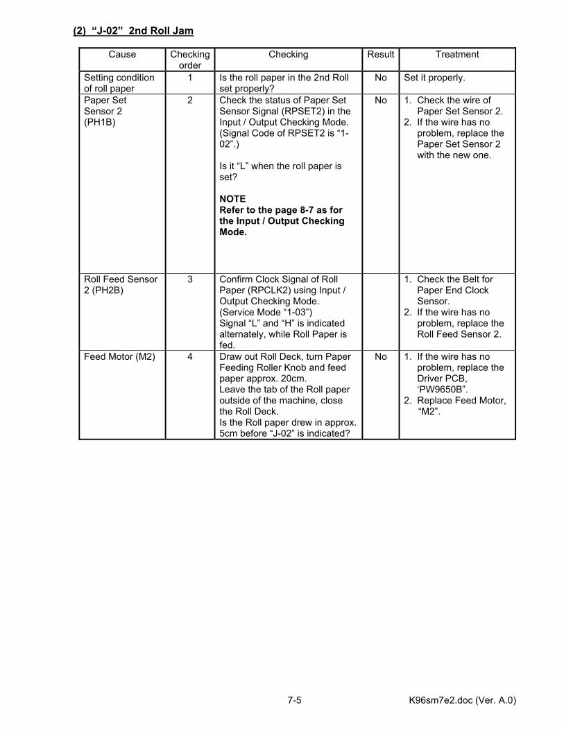
K96sm7e2.doc (Ver. A.0) 7-5
(2) “J-02” 2nd Roll Jam
Cause Checking order
Checking Result Treatment
Setting condition of roll paper
1 Is the roll paper in the 2nd Roll set properly?
No Set it properly.
Paper Set Sensor 2 (PH1B)
2 Check the status of Paper Set Sensor Signal (RPSET2) in the Input / Output Checking Mode. (Signal Code of RPSET2 is “1-02”.) Is it “L” when the roll paper is set? NOTE Refer to the page 8-7 as for the Input / Output Checking Mode.
No 1. Check the wire of Paper Set Sensor 2. 2. If the wire has no problem, replace the Paper Set Sensor 2 with the new one.
Roll Feed Sensor 2 (PH2B)
3 Confirm Clock Signal of Roll Paper (RPCLK2) using Input / Output Checking Mode. (Service Mode “1-03”) Signal “L” and “H” is indicated alternately, while Roll Paper is fed.
1. Check the Belt for Paper End Clock Sensor. 2. If the wire has no problem, replace the Roll Feed Sensor 2.
Feed Motor (M2) 4 Draw out Roll Deck, turn Paper Feeding Roller Knob and feed paper approx. 20cm. Leave the tab of the Roll paper outside of the machine, close the Roll Deck. Is the Roll paper drew in approx. 5cm before “J-02” is indicated?
No 1. If the wire has no problem, replace the Driver PCB, ‘PW9650B”. 2. Replace Feed Motor,
“M2”.

K96sm7e2.doc (Ver. A.0) 7-6
(3) “J-03” 3rd Roll Jam
Cause Checking order
Checking Result Treatment
Setting condition of roll paper
1 Is the roll paper in the 3rd Roll set properly?
No Set it properly.
Paper Set Sensor 3 (PH1C)
2 Check the status of Paper Set Sensor Signal (RPSET3) in the Input / Output Checking Mode. (Signal Code of RPSET3 is “1-04”.) Is it “L” when the roll paper is set? NOTE Refer to the page 8-7 as for the Input / Output Checking Mode.
No 1. Check the wire of Paper Set Sensor 3. 2. If the wire has no problem, replace the Paper Set Sensor 3 with the new one.
Roll Feed Sensor 3 (PH2C)
3 Confirm Clock Signal of Roll Paper (RPCLK3) using Input / Output Checking Mode. (Service Mode “1-05”) Signal “L” and “H” is indicated alternately, while Roll Paper is fed.
1. Check the Belt for Paper End Clock Sensor. 2. If the wire has no problem, replace the Roll Feed Sensor 3.
Feed Motor (M2) 4 Draw out Roll Deck, turn Paper Feeding Roller Knob and feed paper approx. 20cm. Leave the tab of the Roll paper outside of the machine, close the Roll Deck. Is the Roll paper drew in approx. 5cm before “J-03” is indicated?
No 1. If the wire has no problem, replace the Driver PCB, ‘PW9650B”. 2. Replace Feed Motor,
“M2”.
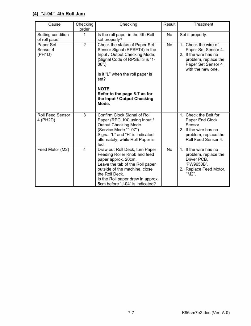
K96sm7e2.doc (Ver. A.0) 7-7
(4) “J-04” 4th Roll Jam
Cause Checking order
Checking Result Treatment
Setting condition of roll paper
1 Is the roll paper in the 4th Roll set properly?
No Set it properly.
Paper Set Sensor 4 (PH1D)
2 Check the status of Paper Set Sensor Signal (RPSET4) in the Input / Output Checking Mode. (Signal Code of RPSET3 is “1-06”.) Is it “L” when the roll paper is set? NOTE Refer to the page 8-7 as for the Input / Output Checking Mode.
No 1. Check the wire of Paper Set Sensor 4. 2. If the wire has no problem, replace the Paper Set Sensor 4 with the new one.
Roll Feed Sensor 4 (PH2D)
3 Confirm Clock Signal of Roll Paper (RPCLK4) using Input / Output Checking Mode. (Service Mode “1-07”) Signal “L” and “H” is indicated alternately, while Roll Paper is fed.
1. Check the Belt for Paper End Clock Sensor. 2. If the wire has no problem, replace the Roll Feed Sensor 4.
Feed Motor (M2) 4 Draw out Roll Deck, turn Paper Feeding Roller Knob and feed paper approx. 20cm. Leave the tab of the Roll paper outside of the machine, close the Roll Deck. Is the Roll paper drew in approx. 5cm before “J-04” is indicated?
No 1. If the wire has no problem, replace the Driver PCB, ‘PW9650B”. 2. Replace Feed Motor,
“M2”.
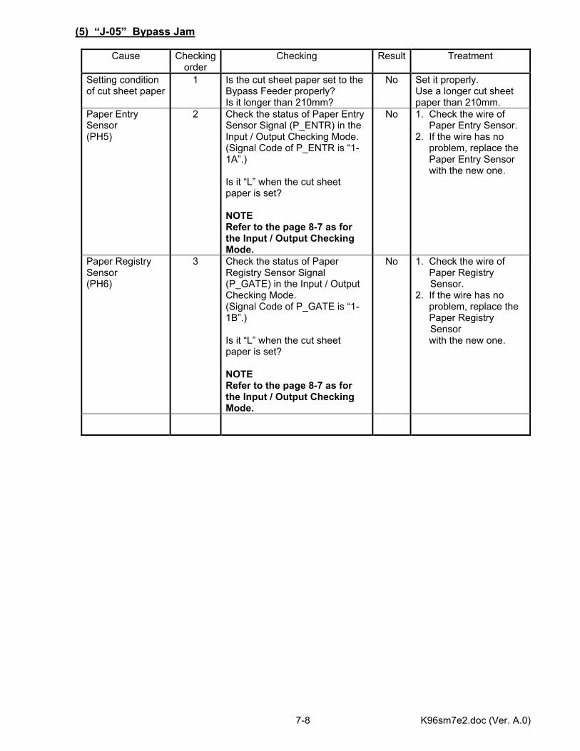
K96sm7e2.doc (Ver. A.0) 7-8
(5) “J-05” Bypass Jam
Cause Checking order
Checking Result Treatment
Setting condition of cut sheet paper
1 Is the cut sheet paper set to the Bypass Feeder properly? Is it longer than 210mm?
No Set it properly. Use a longer cut sheet paper than 210mm.
Paper Entry Sensor (PH5)
2 Check the status of Paper Entry Sensor Signal (P_ENTR) in the Input / Output Checking Mode. (Signal Code of P_ENTR is “1-1A”.) Is it “L” when the cut sheet paper is set? NOTE Refer to the page 8-7 as for the Input / Output Checking Mode.
No 1. Check the wire of Paper Entry Sensor. 2. If the wire has no problem, replace the Paper Entry Sensor with the new one.
Paper Registry Sensor (PH6)
3 Check the status of Paper Registry Sensor Signal (P_GATE) in the Input / Output Checking Mode. (Signal Code of P_GATE is “1-1B”.) Is it “L” when the cut sheet paper is set? NOTE Refer to the page 8-7 as for the Input / Output Checking Mode.
No 1. Check the wire of Paper Registry
Sensor. 2. If the wire has no problem, replace the Paper Registry
Sensor with the new one.
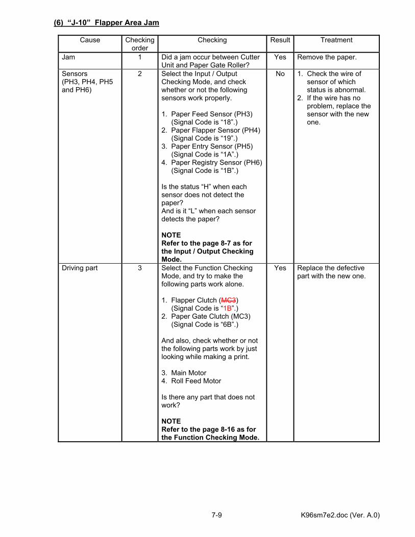
K96sm7e2.doc (Ver. A.0) 7-9
(6) “J-10” Flapper Area Jam
Cause Checking order
Checking Result Treatment
Jam 1 Did a jam occur between Cutter Unit and Paper Gate Roller?
Yes Remove the paper.
Sensors (PH3, PH4, PH5 and PH6)
2 Select the Input / Output Checking Mode, and check whether or not the following sensors work properly. 1. Paper Feed Sensor (PH3) (Signal Code is “18”.) 2. Paper Flapper Sensor (PH4) (Signal Code is “19”.) 3. Paper Entry Sensor (PH5) (Signal Code is “1A”.) 4. Paper Registry Sensor (PH6) (Signal Code is “1B”.) Is the status “H” when each sensor does not detect the paper? And is it “L” when each sensor detects the paper? NOTE Refer to the page 8-7 as for the Input / Output Checking Mode.
No 1. Check the wire of sensor of which status is abnormal. 2. If the wire has no problem, replace the sensor with the new one.
Driving part 3 Select the Function Checking Mode, and try to make the following parts work alone. 1. Flapper Clutch (MC3) (Signal Code is “1B”.) 2. Paper Gate Clutch (MC3) (Signal Code is “6B”.) And also, check whether or not the following parts work by just looking while making a print. 3. Main Motor 4. Roll Feed Motor Is there any part that does not work? NOTE Refer to the page 8-16 as for the Function Checking Mode.
Yes Replace the defective part with the new one.
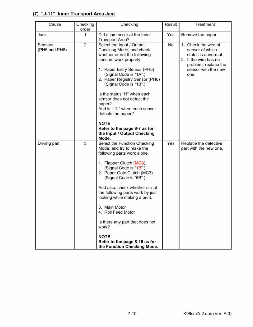
K96sm7e2.doc (Ver. A.0) 7-10
(7) “J-11” Inner Transport Area Jam
Cause Checking order
Checking Result Treatment
Jam 1 Did a jam occur at the Inner Transport Area?
Yes Remove the paper.
Sensors (PH5 and PH6)
2 Select the Input / Output Checking Mode, and check whether or not the following sensors work properly. 1. Paper Entry Sensor (PH5) (Signal Code is “1A”.) 2. Paper Registry Sensor (PH6) (Signal Code is “1B”.) Is the status “H” when each sensor does not detect the paper? And is it “L” when each sensor detects the paper? NOTE Refer to the page 8-7 as for the Input / Output Checking Mode.
No 1. Check the wire of sensor of which status is abnormal. 2. If the wire has no problem, replace the sensor with the new one.
Driving part 3 Select the Function Checking Mode, and try to make the following parts work alone. 1. Flapper Clutch (MC3) (Signal Code is “1B”.) 2. Paper Gate Clutch (MC3) (Signal Code is “6B”.) And also, check whether or not the following parts work by just looking while making a print. 3. Main Motor 4. Roll Feed Motor Is there any part that does not work? NOTE Refer to the page 8-16 as for the Function Checking Mode.
Yes Replace the defective part with the new one.
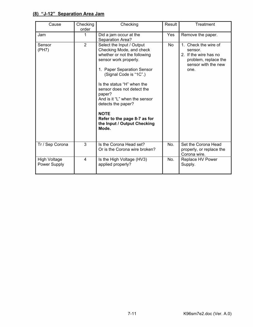
K96sm7e2.doc (Ver. A.0) 7-11
(8) “J-12” Separation Area Jam
Cause Checking order
Checking Result Treatment
Jam 1 Did a jam occur at the Separation Area?
Yes Remove the paper.
Sensor (PH7)
2 Select the Input / Output Checking Mode, and check whether or not the following sensor work properly. 1. Paper Separation Sensor (Signal Code is “1C”.) Is the status “H” when the sensor does not detect the paper? And is it “L” when the sensor detects the paper? NOTE Refer to the page 8-7 as for the Input / Output Checking Mode.
No 1. Check the wire of sensor. 2. If the wire has no problem, replace the sensor with the new one.
Tr / Sep Corona 3 Is the Corona Head set? Or is the Corona wire broken?
No. Set the Corona Head properly, or replace the Corona wire.
High Voltage Power Supply
4 Is the High Voltage (HV3) applied properly?
No. Replace HV Power Supply.
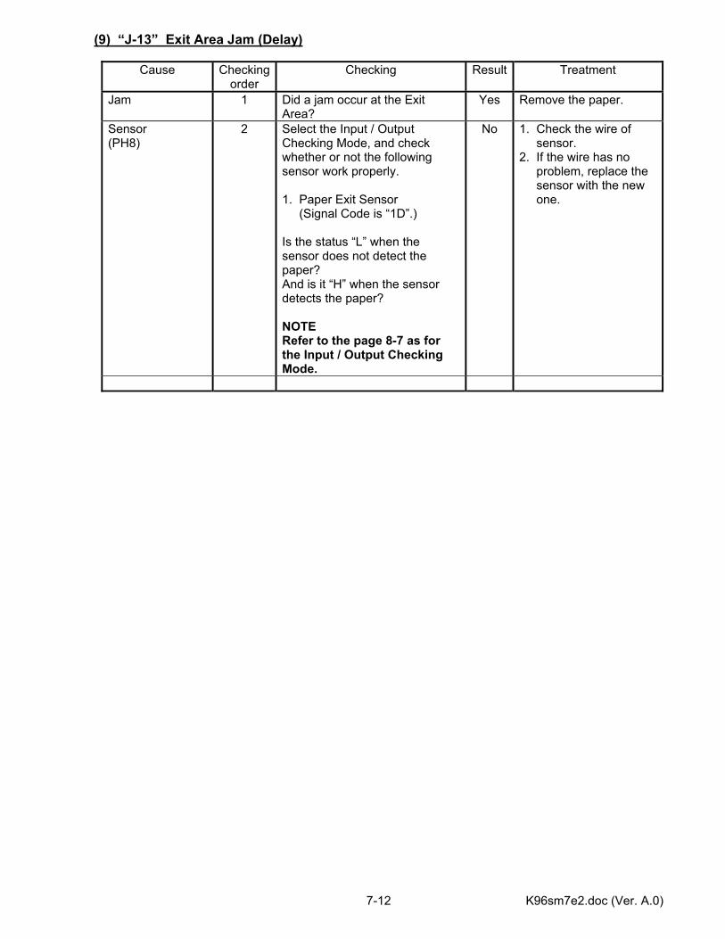
K96sm7e2.doc (Ver. A.0) 7-12
(9) “J-13” Exit Area Jam (Delay)
Cause Checking order
Checking Result Treatment
Jam 1 Did a jam occur at the Exit Area?
Yes Remove the paper.
Sensor (PH8)
2 Select the Input / Output Checking Mode, and check whether or not the following sensor work properly. 1. Paper Exit Sensor (Signal Code is “1D”.) Is the status “L” when the sensor does not detect the paper? And is it “H” when the sensor detects the paper? NOTE Refer to the page 8-7 as for the Input / Output Checking Mode.
No 1. Check the wire of sensor. 2. If the wire has no problem, replace the sensor with the new one.

K96sm7e2.doc (Ver. A.0) 7-13
(10) “J-14” Exit Area Jam (Stay)
Cause Checking order
Checking Result Treatment
Jam 1 Did a jam occur between Separation Area and Exit Area?
Yes Remove the paper.
Sensor (PH8)
2 Select the Input / Output Checking Mode, and check whether or not the following sensor work properly. 1. Paper Exit Sensor (Signal Code is “1D”.) Is the status “L” when the sensor does not detect the paper? And is it “H” when the sensor detects the paper? NOTE Refer to the page 8-7 as for the Input / Output Checking Mode.
No 1. Check the wire of sensor. 2. If the wire has no problem, replace the sensor with the new one.

K96sm7e2.doc (Ver. A.0) 7-14
(11) “U-01” Upper Roll Deck Open Error
Cause Checking order
Checking Result Treatment
Upper Roll Deck 1 Is the Upper Roll Deck opened? Yes Close it. Micro Switch (MS5A)
2 Select the Input / Output Checking Mode, and check the function of next item. 1. Deck Switch 1 (Signal Code is “23”.) Is the status “L” when the Upper Roll Deck is closed? And is it “H” when the Upper Roll Deck is opened? NOTE Refer to the page 8-7 as for the Input / Output Checking Mode.
No 1. Check the wire of Micro Switch. 2. If the wire has no problem, replace the Micro Switch with the
new one.
No Replace the Fuse 902 (5A).
Fuse PCB (PW9690)
3 Check the voltage at J902B-3 on the Fuse PCB with a multi-meter. Is it 24V?
Yes Install the Upper Roll Deck and Lower Roll Deck to the machine properly.
No Check whether or not any wire is broken between Fuse PCB and Driver PCB.
Driver PCB (PW9650B)
4 Check the voltage at J521B-1 on the Driver PCB with a multi-meter. Is it 24V when the Upper Roll Deck and the Lower Roll Deck are closed? Yes Replace the Driver PCB
with the new one.
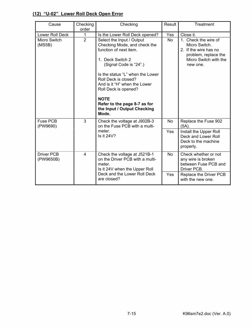
K96sm7e2.doc (Ver. A.0) 7-15
(12) “U-02” Lower Roll Deck Open Error
Cause Checking order
Checking Result Treatment
Lower Roll Deck 1 Is the Lower Roll Deck opened? Yes Close it. Micro Switch (MS5B)
2
Select the Input / Output Checking Mode, and check the function of next item. 1. Deck Switch 2 (Signal Code is “24”.) Is the status “L” when the Lower Roll Deck is closed? And is it “H” when the Lower Roll Deck is opened? NOTE Refer to the page 8-7 as for the Input / Output Checking Mode.
No 1. Check the wire of Micro Switch. 2. If the wire has no problem, replace the Micro Switch with the
new one.
No Replace the Fuse 902 (5A).
Fuse PCB (PW9690)
3 Check the voltage at J902B-3 on the Fuse PCB with a multi-meter. Is it 24V?
Yes Install the Upper Roll Deck and Lower Roll Deck to the machine properly.
No Check whether or not any wire is broken between Fuse PCB and Driver PCB.
Driver PCB (PW9650B)
4 Check the voltage at J521B-1 on the Driver PCB with a multi-meter. Is it 24V when the Upper Roll Deck and the Lower Roll Deck are closed?
Yes Replace the Driver PCB with the new one.

K96sm7e2.doc (Ver. A.0) 7-16
(13) “U-02” Upper Cassette Deck Open Error (Option)
Cause Checking order
Checking Result Treatment
Upper Cassette Deck
1 Is the Upper Cassette Deck opened?
Yes Close it.
Micro Switch (MS6A)
2
Select the Input / Output Checking Mode, and check the function of next item. 1. Upper Cassette Deck Switch (Signal Code is “4F”.) Is the status “L” when the Upper Cassette Deck is closed? And is it “H” when the Upper Cassette Deck is opened? NOTE Refer to the page 8-7 as for the Input / Output Checking Mode.
No 1. Check the wire of Micro Switch. 2. If the wire has no problem, replace the Micro Switch with the
new one.
No Replace the Fuse 902 (5A).
Fuse PCB (PW9690)
3 Check the voltage at J902B-4 on the Fuse PCB with a multi-meter. Is it 24V?
Yes Install the Upper Cassette Deck to the machine properly.
No Check whether or not any wire is broken between CN2A-3(DCP1) and Driver PCB.
Driver PCB (PW9651A)
4 Check the voltage at J501A-2 on the Driver PCB with a multi-meter. Is it 5V?
Yes Replace the Driver PCB with the new one.
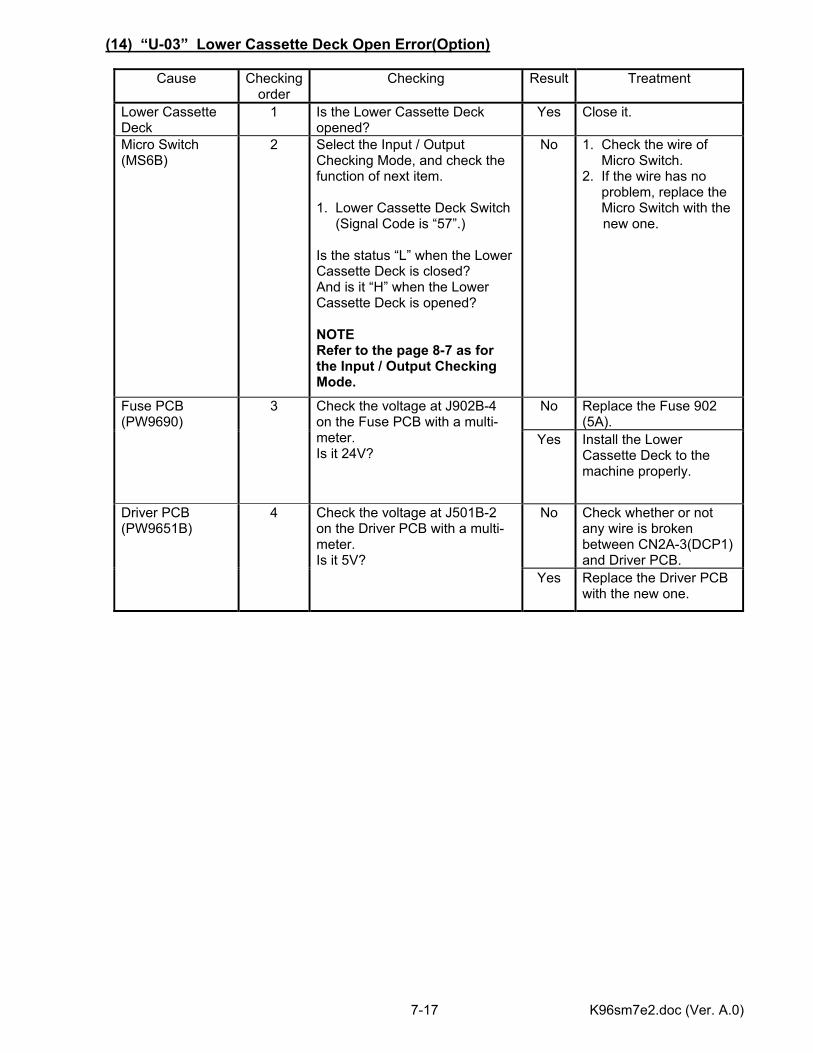
K96sm7e2.doc (Ver. A.0) 7-17
(14) “U-03” Lower Cassette Deck Open Error(Option)
Cause Checking order
Checking Result Treatment
Lower Cassette Deck
1 Is the Lower Cassette Deck opened?
Yes Close it.
Micro Switch (MS6B)
2
Select the Input / Output Checking Mode, and check the function of next item. 1. Lower Cassette Deck Switch (Signal Code is “57”.) Is the status “L” when the Lower Cassette Deck is closed? And is it “H” when the Lower Cassette Deck is opened? NOTE Refer to the page 8-7 as for the Input / Output Checking Mode.
No 1. Check the wire of Micro Switch. 2. If the wire has no problem, replace the Micro Switch with the
new one.
No Replace the Fuse 902 (5A).
Fuse PCB (PW9690)
3 Check the voltage at J902B-4 on the Fuse PCB with a multi-meter. Is it 24V?
Yes Install the Lower Cassette Deck to the machine properly.
No Check whether or not any wire is broken between CN2A-3(DCP1) and Driver PCB.
Driver PCB (PW9651B)
4 Check the voltage at J501B-2 on the Driver PCB with a multi-meter. Is it 5V?
Yes Replace the Driver PCB with the new one.
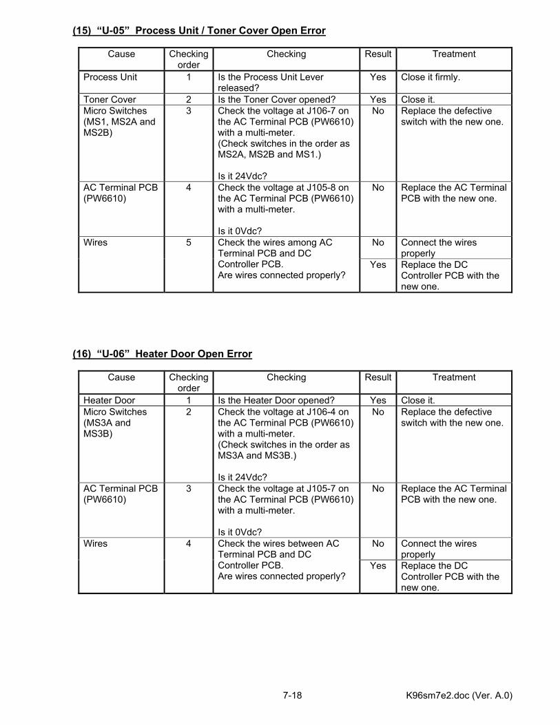
K96sm7e2.doc (Ver. A.0) 7-18
(15) “U-05” Process Unit / Toner Cover Open Error
Cause Checking order
Checking Result Treatment
Process Unit 1 Is the Process Unit Lever released?
Yes Close it firmly.
Toner Cover 2 Is the Toner Cover opened? Yes Close it. Micro Switches (MS1, MS2A and MS2B)
3 Check the voltage at J106-7 on the AC Terminal PCB (PW6610) with a multi-meter. (Check switches in the order as MS2A, MS2B and MS1.) Is it 24Vdc?
No Replace the defective switch with the new one.
AC Terminal PCB (PW6610)
4 Check the voltage at J105-8 on the AC Terminal PCB (PW6610) with a multi-meter. Is it 0Vdc?
No Replace the AC Terminal PCB with the new one.
No Connect the wires properly
Wires 5 Check the wires among AC Terminal PCB and DC Controller PCB. Are wires connected properly?
Yes Replace the DC Controller PCB with the new one.
(16) “U-06” Heater Door Open Error
Cause Checking order
Checking Result Treatment
Heater Door 1 Is the Heater Door opened? Yes Close it. Micro Switches (MS3A and MS3B)
2 Check the voltage at J106-4 on the AC Terminal PCB (PW6610) with a multi-meter. (Check switches in the order as MS3A and MS3B.) Is it 24Vdc?
No Replace the defective switch with the new one.
AC Terminal PCB (PW6610)
3 Check the voltage at J105-7 on the AC Terminal PCB (PW6610) with a multi-meter. Is it 0Vdc?
No Replace the AC Terminal PCB with the new one.
No Connect the wires properly
Wires 4 Check the wires between AC Terminal PCB and DC Controller PCB. Are wires connected properly?
Yes Replace the DC Controller PCB with the new one.
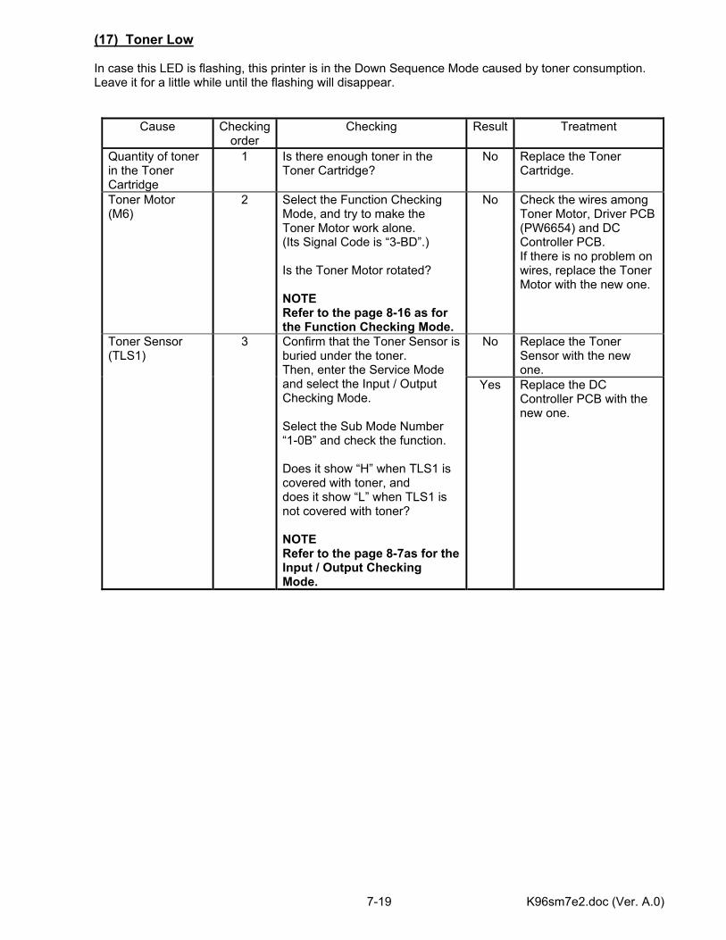
K96sm7e2.doc (Ver. A.0) 7-19
(17) Toner Low In case this LED is flashing, this printer is in the Down Sequence Mode caused by toner consumption. Leave it for a little while until the flashing will disappear.
Cause Checking order
Checking Result Treatment
Quantity of toner in the Toner Cartridge
1 Is there enough toner in the Toner Cartridge?
No Replace the Toner Cartridge.
Toner Motor (M6)
2 Select the Function Checking Mode, and try to make the Toner Motor work alone. (Its Signal Code is “3-BD”.) Is the Toner Motor rotated? NOTE Refer to the page 8-16 as for the Function Checking Mode.
No Check the wires among Toner Motor, Driver PCB (PW6654) and DC Controller PCB. If there is no problem on wires, replace the Toner Motor with the new one.
No Replace the Toner Sensor with the new one.
Toner Sensor (TLS1)
3 Confirm that the Toner Sensor is buried under the toner. Then, enter the Service Mode and select the Input / Output Checking Mode. Select the Sub Mode Number “1-0B” and check the function. Does it show “H” when TLS1 is covered with toner, and does it show “L” when TLS1 is not covered with toner? NOTE Refer to the page 8-7as for the Input / Output Checking Mode.
Yes Replace the DC Controller PCB with the new one.
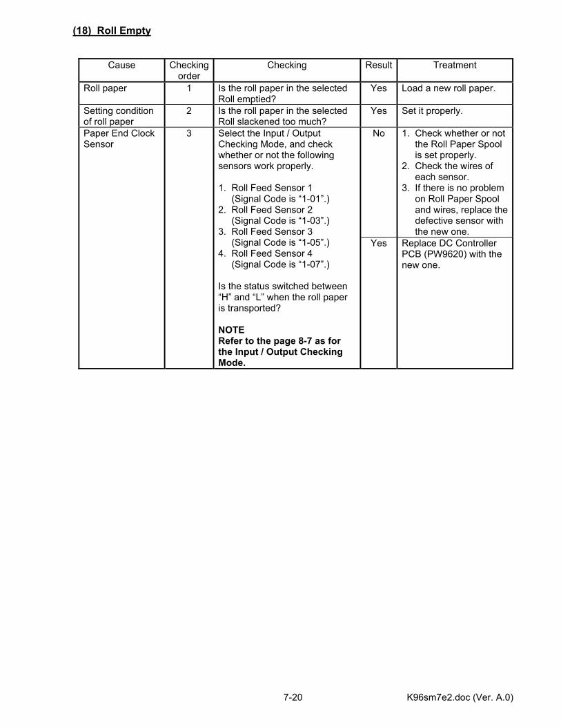
K96sm7e2.doc (Ver. A.0) 7-20
(18) Roll Empty
Cause Checking order
Checking Result Treatment
Roll paper 1 Is the roll paper in the selected Roll emptied?
Yes Load a new roll paper.
Setting condition of roll paper
2 Is the roll paper in the selected Roll slackened too much?
Yes Set it properly.
No 1. Check whether or not the Roll Paper Spool is set properly. 2. Check the wires of each sensor. 3. If there is no problem on Roll Paper Spool and wires, replace the defective sensor with the new one.
Paper End Clock Sensor
3 Select the Input / Output Checking Mode, and check whether or not the following sensors work properly. 1. Roll Feed Sensor 1 (Signal Code is “1-01”.) 2. Roll Feed Sensor 2 (Signal Code is “1-03”.) 3. Roll Feed Sensor 3 (Signal Code is “1-05”.) 4. Roll Feed Sensor 4 (Signal Code is “1-07”.) Is the status switched between “H” and “L” when the roll paper is transported? NOTE Refer to the page 8-7 as for the Input / Output Checking Mode.
Yes Replace DC Controller PCB (PW9620) with the new one.
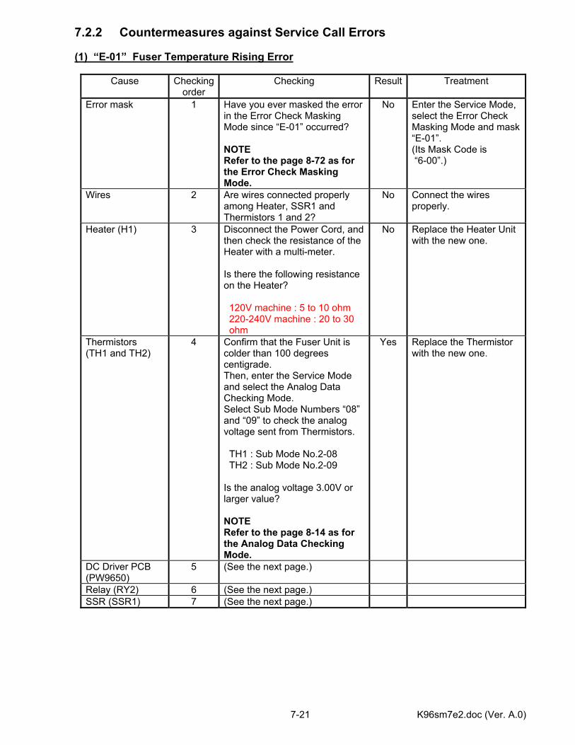
K96sm7e2.doc (Ver. A.0) 7-21
7.2.2 Countermeasures against Service Call Errors (1) “E-01” Fuser Temperature Rising Error
Cause Checking order
Checking Result Treatment
Error mask 1 Have you ever masked the error in the Error Check Masking Mode since “E-01” occurred? NOTE Refer to the page 8-72 as for the Error Check Masking Mode.
No Enter the Service Mode, select the Error Check Masking Mode and mask “E-01”. (Its Mask Code is “6-00”.)
Wires 2 Are wires connected properly among Heater, SSR1 and Thermistors 1 and 2?
No Connect the wires properly.
Heater (H1) 3 Disconnect the Power Cord, and then check the resistance of the Heater with a multi-meter. Is there the following resistance on the Heater? 120V machine : 5 to 10 ohm 220-240V machine : 20 to 30 ohm
No Replace the Heater Unit with the new one.
Thermistors (TH1 and TH2)
4 Confirm that the Fuser Unit is colder than 100 degrees centigrade. Then, enter the Service Mode and select the Analog Data Checking Mode. Select Sub Mode Numbers “08” and “09” to check the analog voltage sent from Thermistors. TH1 : Sub Mode No.2-08 TH2 : Sub Mode No.2-09 Is the analog voltage 3.00V or larger value? NOTE Refer to the page 8-14 as for the Analog Data Checking Mode.
Yes Replace the Thermistor with the new one.
DC Driver PCB (PW9650)
5 (See the next page.)
Relay (RY2) 6 (See the next page.) SSR (SSR1) 7 (See the next page.)
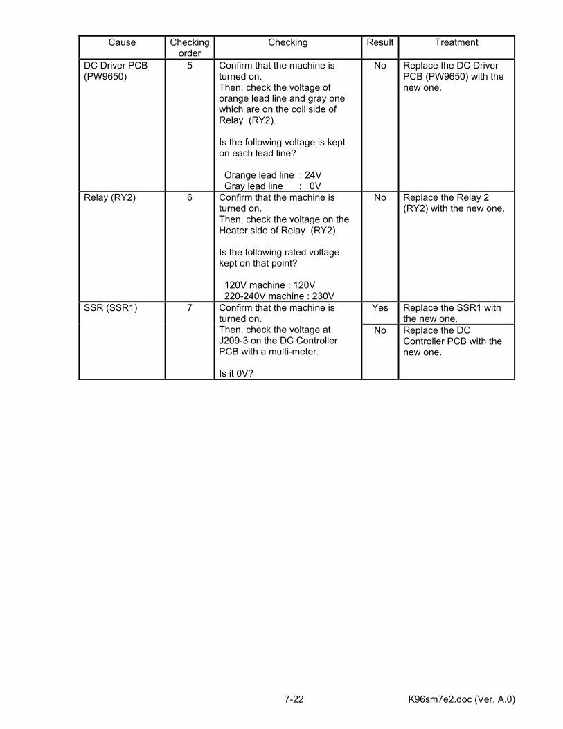
K96sm7e2.doc (Ver. A.0) 7-22
Cause Checking
order Checking Result Treatment
DC Driver PCB (PW9650)
5 Confirm that the machine is turned on. Then, check the voltage of orange lead line and gray one which are on the coil side of Relay (RY2). Is the following voltage is kept on each lead line? Orange lead line : 24V Gray lead line : 0V
No Replace the DC Driver PCB (PW9650) with the new one.
Relay (RY2) 6 Confirm that the machine is turned on. Then, check the voltage on the Heater side of Relay (RY2). Is the following rated voltage kept on that point? 120V machine : 120V 220-240V machine : 230V
No Replace the Relay 2 (RY2) with the new one.
Yes Replace the SSR1 with the new one.
SSR (SSR1) 7 Confirm that the machine is turned on. Then, check the voltage at J209-3 on the DC Controller PCB with a multi-meter. Is it 0V?
No Replace the DC Controller PCB with the new one.
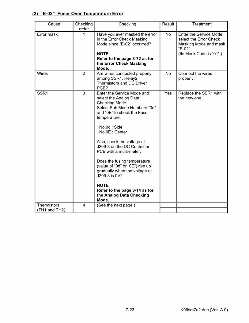
K96sm7e2.doc (Ver. A.0) 7-23
(2) “E-02” Fuser Over Temperature Error
Cause Checking order
Checking Result Treatment
Error mask 1 Have you ever masked the error in the Error Check Masking Mode since “E-02” occurred? NOTE Refer to the page 8-72 as for the Error Check Masking Mode.
No Enter the Service Mode, select the Error Check Masking Mode and mask “E-02”. (Its Mask Code is “01”.)
Wires 2 Are wires connected properly among SSR1, Relay2, Thermistors and DC Driver PCB?
No Connect the wires properly.
SSR1 3 Enter the Service Mode and select the Analog Data Checking Mode. Select Sub Mode Numbers “0d” and “0E” to check the Fuser temperature. No.0d : Side No.0E : Center Also, check the voltage at J209-3 on the DC Controller PCB with a multi-meter. Does the fusing temperature (value of “0d” or “0E”) rise up gradually when the voltage at J209-3 is 0V? NOTE Refer to the page 8-14 as for the Analog Data Checking Mode.
Yes Replace the SSR1 with the new one.
Thermistors (TH1 and TH2)
4 (See the next page.)
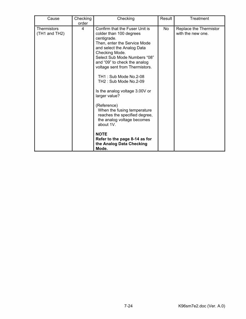
K96sm7e2.doc (Ver. A.0) 7-24
Cause Checking
order Checking Result Treatment
Thermistors (TH1 and TH2)
4 Confirm that the Fuser Unit is colder than 100 degrees centigrade. Then, enter the Service Mode and select the Analog Data Checking Mode. Select Sub Mode Numbers “08” and “09” to check the analog voltage sent from Thermistors. TH1 : Sub Mode No.2-08 TH2 : Sub Mode No.2-09 Is the analog voltage 3.00V or larger value? (Reference) When the fusing temperature reaches the specified degree, the analog voltage becomes about 1V. NOTE Refer to the page 8-14 as for the Analog Data Checking Mode.
No Replace the Thermistor with the new one.
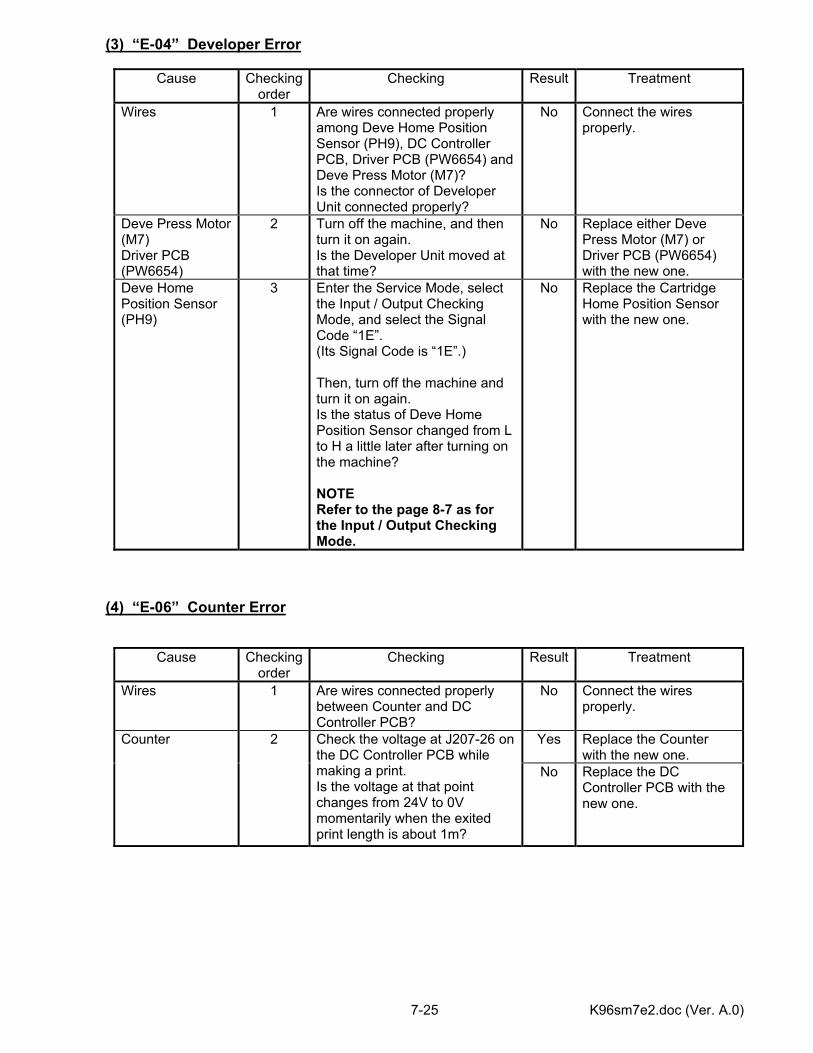
K96sm7e2.doc (Ver. A.0) 7-25
(3) “E-04” Developer Error
Cause Checking order
Checking Result Treatment
Wires 1 Are wires connected properly among Deve Home Position Sensor (PH9), DC Controller PCB, Driver PCB (PW6654) and Deve Press Motor (M7)? Is the connector of Developer Unit connected properly?
No Connect the wires properly.
Deve Press Motor (M7) Driver PCB (PW6654)
2 Turn off the machine, and then turn it on again. Is the Developer Unit moved at that time?
No Replace either Deve Press Motor (M7) or Driver PCB (PW6654) with the new one.
Deve Home Position Sensor (PH9)
3 Enter the Service Mode, select the Input / Output Checking Mode, and select the Signal Code “1E”. (Its Signal Code is “1E”.) Then, turn off the machine and turn it on again. Is the status of Deve Home Position Sensor changed from L to H a little later after turning on the machine? NOTE Refer to the page 8-7 as for the Input / Output Checking Mode.
No Replace the Cartridge Home Position Sensor with the new one.
(4) “E-06” Counter Error
Cause Checking order
Checking Result Treatment
Wires 1 Are wires connected properly between Counter and DC Controller PCB?
No Connect the wires properly.
Yes Replace the Counter with the new one.
Counter 2 Check the voltage at J207-26 on the DC Controller PCB while making a print. Is the voltage at that point changes from 24V to 0V momentarily when the exited print length is about 1m?
No Replace the DC Controller PCB with the new one.
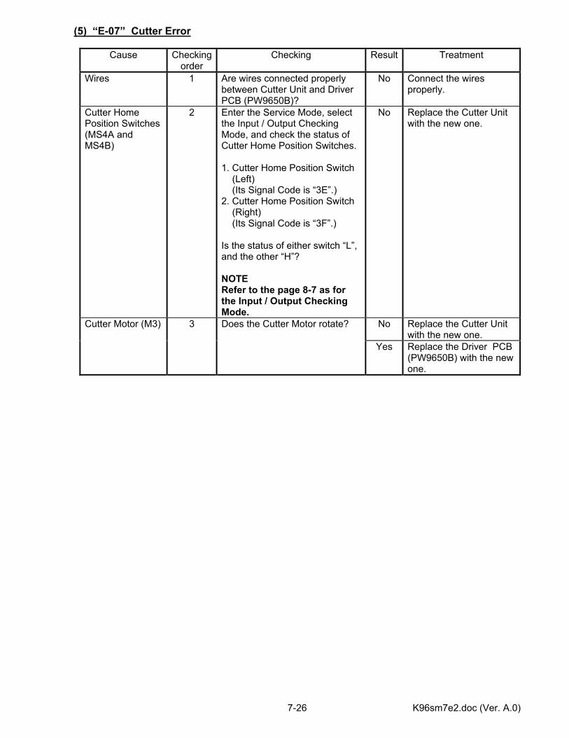
K96sm7e2.doc (Ver. A.0) 7-26
(5) “E-07” Cutter Error
Cause Checking order
Checking Result Treatment
Wires 1 Are wires connected properly between Cutter Unit and Driver PCB (PW9650B)?
No Connect the wires properly.
Cutter Home Position Switches (MS4A and MS4B)
2 Enter the Service Mode, select the Input / Output Checking Mode, and check the status of Cutter Home Position Switches. 1. Cutter Home Position Switch (Left) (Its Signal Code is “3E”.) 2. Cutter Home Position Switch (Right) (Its Signal Code is “3F”.) Is the status of either switch “L”, and the other “H”? NOTE Refer to the page 8-7 as for the Input / Output Checking Mode.
No Replace the Cutter Unit with the new one.
No Replace the Cutter Unit with the new one.
Cutter Motor (M3) 3 Does the Cutter Motor rotate?
Yes Replace the Driver PCB (PW9650B) with the new one.
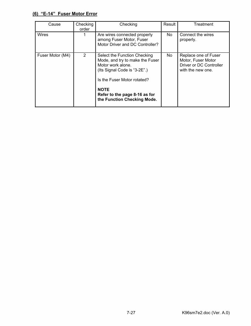
K96sm7e2.doc (Ver. A.0) 7-27
(6) “E-14” Fuser Motor Error
Cause Checking order
Checking Result Treatment
Wires 1 Are wires connected properly among Fuser Motor, Fuser Motor Driver and DC Controller?
No Connect the wires properly.
Fuser Motor (M4) 2 Select the Function Checking Mode, and try to make the Fuser Motor work alone. (Its Signal Code is “3-2E”.) Is the Fuser Motor rotated? NOTE Refer to the page 8-16 as for the Function Checking Mode.
No Replace one of Fuser Motor, Fuser Motor Driver or DC Controller with the new one.
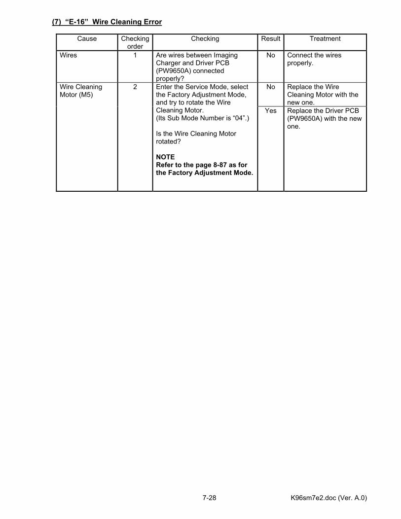
K96sm7e2.doc (Ver. A.0) 7-28
(7) “E-16” Wire Cleaning Error
Cause Checking order
Checking Result Treatment
Wires 1 Are wires between Imaging Charger and Driver PCB (PW9650A) connected properly?
No Connect the wires properly.
No Replace the Wire Cleaning Motor with the new one.
Wire Cleaning Motor (M5)
2 Enter the Service Mode, select the Factory Adjustment Mode, and try to rotate the Wire Cleaning Motor. (Its Sub Mode Number is “04”.) Is the Wire Cleaning Motor rotated? NOTE Refer to the page 8-87 as for the Factory Adjustment Mode.
Yes Replace the Driver PCB (PW9650A) with the new one.
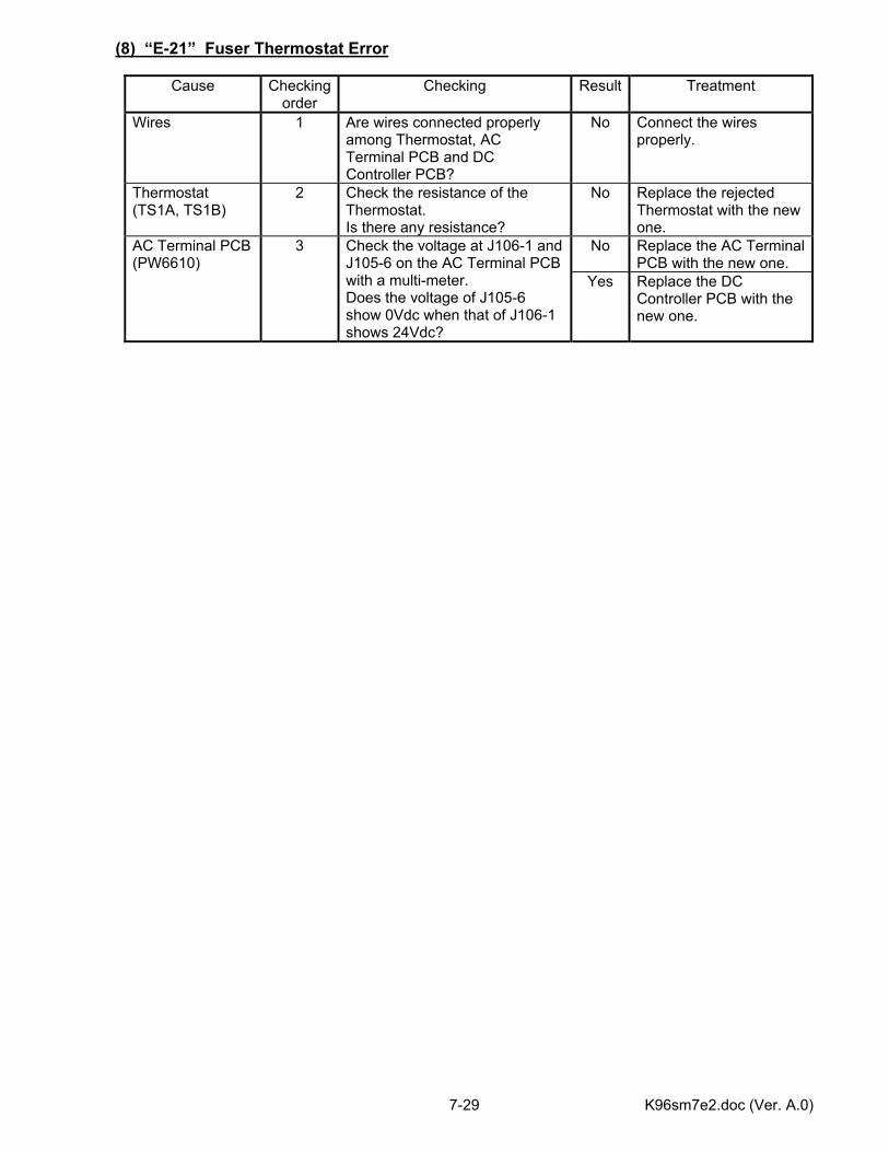
K96sm7e2.doc (Ver. A.0) 7-29
(8) “E-21” Fuser Thermostat Error
Cause Checking order
Checking Result Treatment
Wires 1 Are wires connected properly among Thermostat, AC Terminal PCB and DC Controller PCB?
No Connect the wires properly.
Thermostat (TS1A, TS1B)
2 Check the resistance of the Thermostat. Is there any resistance?
No Replace the rejected Thermostat with the new one.
No Replace the AC Terminal PCB with the new one.
AC Terminal PCB (PW6610)
3 Check the voltage at J106-1 and J105-6 on the AC Terminal PCB with a multi-meter. Does the voltage of J105-6 show 0Vdc when that of J106-1 shows 24Vdc?
Yes Replace the DC Controller PCB with the new one.
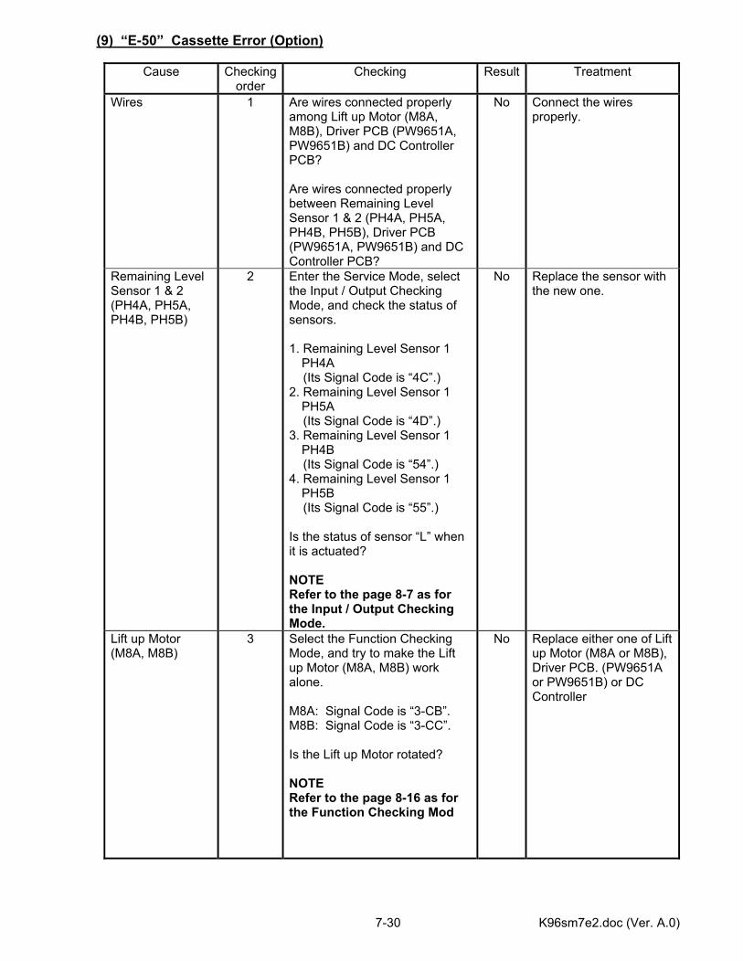
K96sm7e2.doc (Ver. A.0) 7-30
(9) “E-50” Cassette Error (Option)
Cause Checking order
Checking Result Treatment
Wires 1 Are wires connected properly among Lift up Motor (M8A, M8B), Driver PCB (PW9651A, PW9651B) and DC Controller PCB? Are wires connected properly between Remaining Level Sensor 1 & 2 (PH4A, PH5A, PH4B, PH5B), Driver PCB (PW9651A, PW9651B) and DC Controller PCB?
No Connect the wires properly.
Remaining Level Sensor 1 & 2 (PH4A, PH5A, PH4B, PH5B)
2 Enter the Service Mode, select the Input / Output Checking Mode, and check the status of sensors. 1. Remaining Level Sensor 1
PH4A (Its Signal Code is “4C”.) 2. Remaining Level Sensor 1
PH5A (Its Signal Code is “4D”.) 3. Remaining Level Sensor 1
PH4B (Its Signal Code is “54”.) 4. Remaining Level Sensor 1
PH5B (Its Signal Code is “55”.) Is the status of sensor “L” when it is actuated? NOTE Refer to the page 8-7 as for the Input / Output Checking Mode.
No Replace the sensor with the new one.
Lift up Motor (M8A, M8B)
3 Select the Function Checking Mode, and try to make the Lift up Motor (M8A, M8B) work alone. M8A: Signal Code is “3-CB”. M8B: Signal Code is “3-CC”. Is the Lift up Motor rotated? NOTE Refer to the page 8-16 as for the Function Checking Mod
No Replace either one of Lift up Motor (M8A or M8B), Driver PCB. (PW9651A or PW9651B) or DC Controller
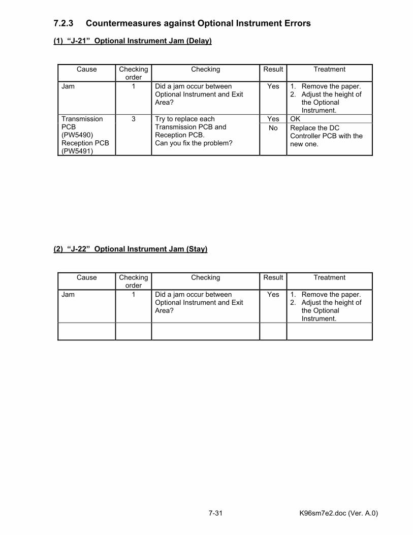
K96sm7e2.doc (Ver. A.0) 7-31
7.2.3 Countermeasures against Optional Instrument Errors (1) “J-21” Optional Instrument Jam (Delay)
(2) “J-22” Optional Instrument Jam (Stay)
Cause Checking order
Checking Result Treatment
Jam 1 Did a jam occur between Optional Instrument and Exit Area?
Yes 1. Remove the paper. 2. Adjust the height of
the Optional Instrument.
Yes OK Transmission PCB (PW5490) Reception PCB (PW5491)
3 Try to replace each Transmission PCB and Reception PCB. Can you fix the problem?
No Replace the DC Controller PCB with the new one.
Cause Checking order
Checking Result Treatment
Jam 1 Did a jam occur between Optional Instrument and Exit Area?
Yes 1. Remove the paper. 2. Adjust the height of
the Optional Instrument.
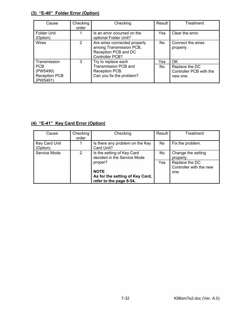
K96sm7e2.doc (Ver. A.0) 7-32
(3) “E-40” Folder Error (Option)
Cause Checking order
Checking Result Treatment
Folder Unit (Option)
1 Is an error occurred on the optional Folder Unit?
Yes Clear the error.
Wires 2 Are wires connected properly among Transmission PCB, Reception PCB and DC Controller PCB?
No Connect the wires properly.
Yes OK Transmission PCB (PW5490) Reception PCB (PW5491)
3 Try to replace each Transmission PCB and Reception PCB. Can you fix the problem?
No Replace the DC Controller PCB with the new one.
(4) “E-41” Key Card Error (Option)
Cause Checking order
Checking Result Treatment
Key Card Unit (Option)
1 Is there any problem on the Key Card Unit?
No Fix the problem.
No Change the setting properly.
Service Mode 2 Is the setting of Key Card decided in the Service Mode proper? NOTE As for the setting of Key Card, refer to the page 8-54.
Yes Replace the DC Controller with the new one.
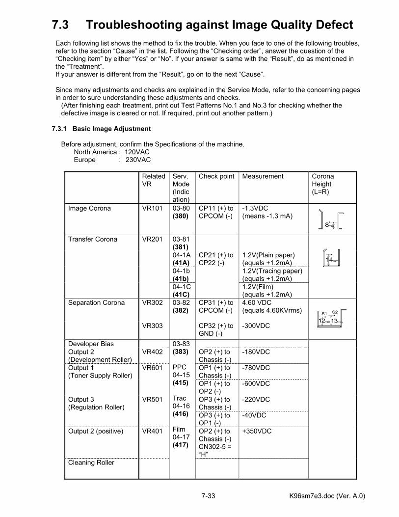
K96sm7e3.doc (Ver. A.0) 7-33
7.3 Troubleshooting against Image Quality Defect Each following list shows the method to fix the trouble. When you face to one of the following troubles, refer to the section “Cause” in the list. Following the “Checking order”, answer the question of the “Checking item” by either “Yes” or “No”. If your answer is same with the “Result”, do as mentioned in the “Treatment”. If your answer is different from the “Result”, go on to the next “Cause”. Since many adjustments and checks are explained in the Service Mode, refer to the concerning pages in order to sure understanding these adjustments and checks. (After finishing each treatment, print out Test Patterns No.1 and No.3 for checking whether the defective image is cleared or not. If required, print out another pattern.) 7.3.1 Basic Image Adjustment Before adjustment, confirm the Specifications of the machine. North America : 120VAC Europe : 230VAC
Related VR
Serv. Mode (Indication)
Check point Measurement Corona Height (L=R)
Image Corona VR101 03-80 (380)
CP11 (+) to CPCOM (-)
-1.3VDC (means -1.3 mA)
VR201 03-81 (381)
04-1A (41A)
1.2V(Plain paper) (equals +1.2mA)
04-1b (41b)
1.2V(Tracing paper) (equals +1.2mA)
Transfer Corona
04-1C (41C)
CP21 (+) to CP22 (-)
1.2V(Film) (equals +1.2mA)
VR302 CP31 (+) to CPCOM (-)
4.60 VDC (equals 4.60KVrms)
Separation Corona
VR303
03-82 (382)
CP32 (+) to GND (-)
-300VDC
Developer Bias Output 2 (Development Roller)
VR402 OP2 (+) to Chassis (-)
-180VDC
OP1 (+) to Chassis (-)
-780VDC Output 1 (Toner Supply Roller)
VR601
OP1 (+) to OP2 (-)
-600VDC
OP3 (+) to Chassis (-)
-220VDC Output 3 (Regulation Roller)
VR501
OP3 (+) to OP1 (-)
-40VDC
Output 2 (positive) VR401
03-83 (383) PPC 04-15 (415) Trac 04-16 (416) Film 04-17 (417)
OP2 (+) to Chassis (-) CN302-5 = “H”
+350VDC
Cleaning Roller
8mm
14mm
12mm13mm
S1 S2
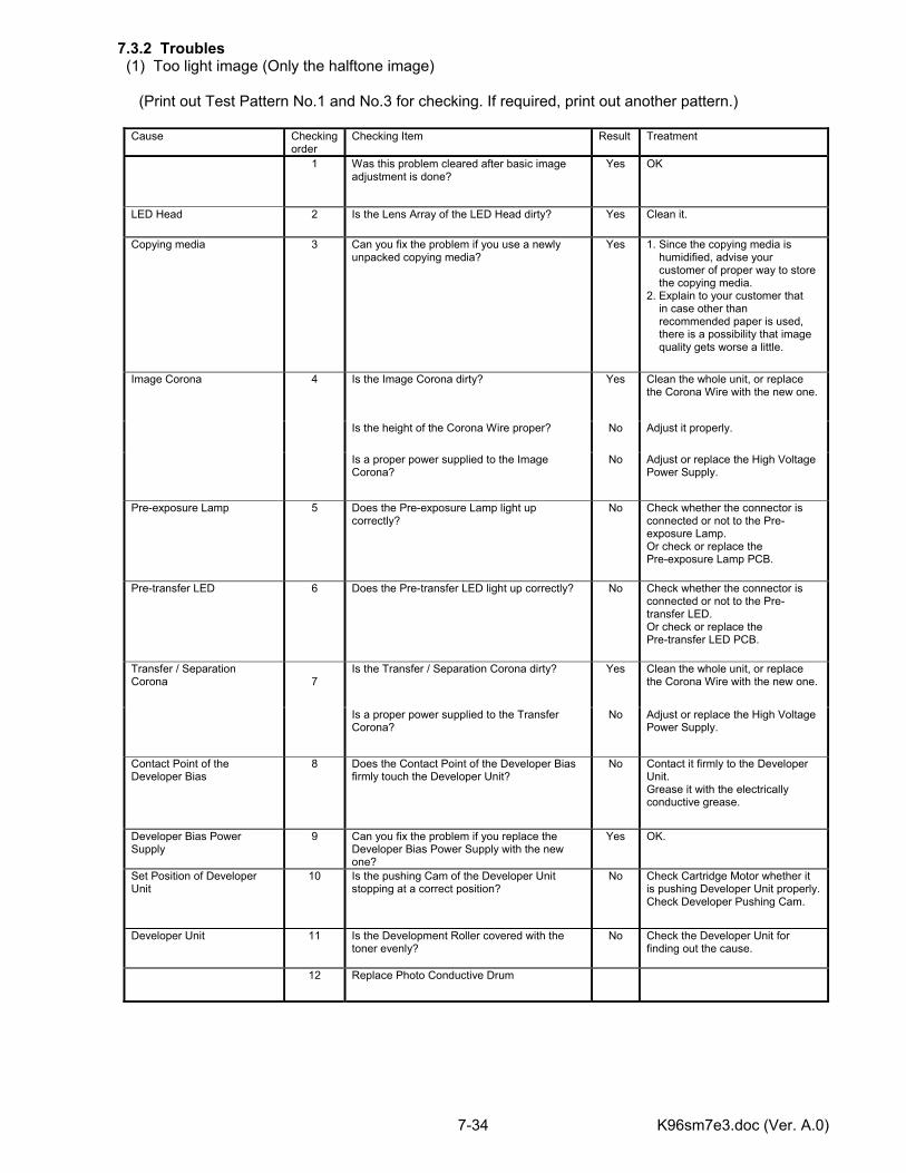
K96sm7e3.doc (Ver. A.0) 7-34
7.3.2 Troubles (1) Too light image (Only the halftone image) (Print out Test Pattern No.1 and No.3 for checking. If required, print out another pattern.)
Cause Checking order
Checking Item Result Treatment
1 Was this problem cleared after basic image adjustment is done?
Yes OK
LED Head 2 Is the Lens Array of the LED Head dirty? Yes Clean it.
Copying media 3 Can you fix the problem if you use a newly unpacked copying media?
Yes 1. Since the copying media is humidified, advise your customer of proper way to store the copying media. 2. Explain to your customer that in case other than recommended paper is used, there is a possibility that image quality gets worse a little.
Is the Image Corona dirty? Yes Clean the whole unit, or replace the Corona Wire with the new one.
Is the height of the Corona Wire proper? No Adjust it properly.
Image Corona 4
Is a proper power supplied to the Image Corona?
No Adjust or replace the High Voltage Power Supply.
Pre-exposure Lamp 5 Does the Pre-exposure Lamp light up correctly?
No Check whether the connector is connected or not to the Pre-exposure Lamp. Or check or replace the Pre-exposure Lamp PCB.
Pre-transfer LED 6 Does the Pre-transfer LED light up correctly? No Check whether the connector is connected or not to the Pre-transfer LED. Or check or replace the Pre-transfer LED PCB.
Is the Transfer / Separation Corona dirty? Yes Clean the whole unit, or replace the Corona Wire with the new one.
Transfer / Separation Corona
7
Is a proper power supplied to the Transfer Corona?
No Adjust or replace the High Voltage Power Supply.
Contact Point of the Developer Bias
8 Does the Contact Point of the Developer Bias firmly touch the Developer Unit?
No Contact it firmly to the Developer Unit. Grease it with the electrically conductive grease.
Developer Bias Power Supply
9 Can you fix the problem if you replace the Developer Bias Power Supply with the new one?
Yes OK.
Set Position of Developer Unit
10 Is the pushing Cam of the Developer Unit stopping at a correct position?
No Check Cartridge Motor whether it is pushing Developer Unit properly. Check Developer Pushing Cam.
Developer Unit 11 Is the Development Roller covered with the toner evenly?
No Check the Developer Unit for finding out the cause.
12 Replace Photo Conductive Drum
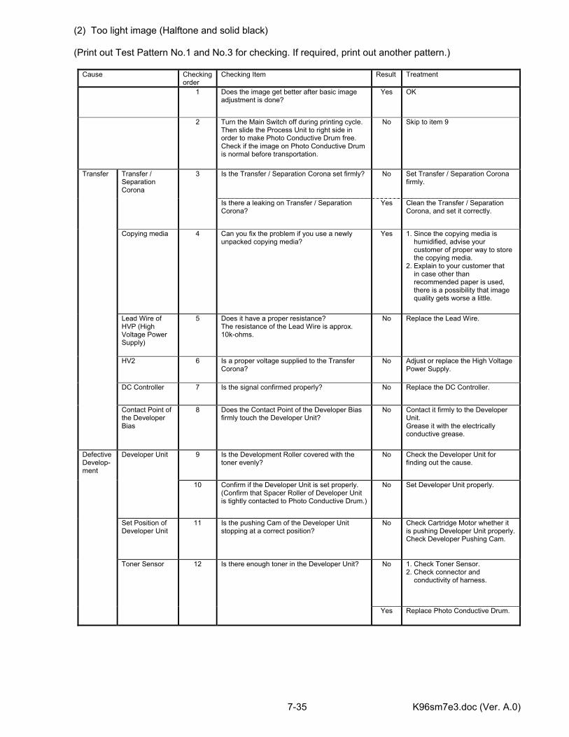
K96sm7e3.doc (Ver. A.0) 7-35
(2) Too light image (Halftone and solid black) (Print out Test Pattern No.1 and No.3 for checking. If required, print out another pattern.)
Cause Checking order
Checking Item Result Treatment
1 Does the image get better after basic image adjustment is done?
Yes OK
2 Turn the Main Switch off during printing cycle. Then slide the Process Unit to right side in order to make Photo Conductive Drum free. Check if the image on Photo Conductive Drum is normal before transportation.
No Skip to item 9
Is the Transfer / Separation Corona set firmly? No Set Transfer / Separation Corona firmly.
Transfer / Separation Corona
3
Is there a leaking on Transfer / Separation Corona?
Yes Clean the Transfer / Separation Corona, and set it correctly.
Copying media 4 Can you fix the problem if you use a newly unpacked copying media?
Yes 1. Since the copying media is humidified, advise your customer of proper way to store the copying media. 2. Explain to your customer that in case other than recommended paper is used, there is a possibility that image quality gets worse a little.
Lead Wire of HVP (High Voltage Power Supply)
5 Does it have a proper resistance? The resistance of the Lead Wire is approx. 10k-ohms.
No Replace the Lead Wire.
HV2 6 Is a proper voltage supplied to the Transfer Corona?
No Adjust or replace the High Voltage Power Supply.
DC Controller 7 Is the signal confirmed properly? No Replace the DC Controller.
Transfer
Contact Point of the Developer Bias
8 Does the Contact Point of the Developer Bias firmly touch the Developer Unit?
No Contact it firmly to the Developer Unit. Grease it with the electrically conductive grease.
9 Is the Development Roller covered with the toner evenly?
No Check the Developer Unit for finding out the cause.
Developer Unit
10 Confirm if the Developer Unit is set properly. (Confirm that Spacer Roller of Developer Unit is tightly contacted to Photo Conductive Drum.)
No Set Developer Unit properly.
Set Position of Developer Unit
11 Is the pushing Cam of the Developer Unit stopping at a correct position?
No Check Cartridge Motor whether it is pushing Developer Unit properly. Check Developer Pushing Cam.
No 1. Check Toner Sensor. 2. Check connector and conductivity of harness.
Defective Develop-ment
Toner Sensor 12 Is there enough toner in the Developer Unit?
Yes Replace Photo Conductive Drum.
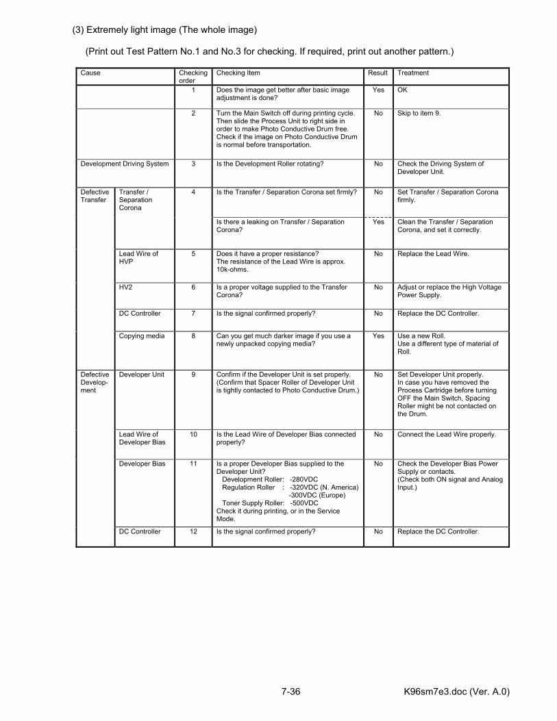
K96sm7e3.doc (Ver. A.0) 7-36
(3) Extremely light image (The whole image) (Print out Test Pattern No.1 and No.3 for checking. If required, print out another pattern.)
Cause Checking order
Checking Item Result Treatment
1 Does the image get better after basic image adjustment is done?
Yes OK
2 Turn the Main Switch off during printing cycle. Then slide the Process Unit to right side in order to make Photo Conductive Drum free. Check if the image on Photo Conductive Drum is normal before transportation.
No Skip to item 9.
Development Driving System 3 Is the Development Roller rotating? No Check the Driving System of Developer Unit.
Is the Transfer / Separation Corona set firmly? No Set Transfer / Separation Corona firmly.
Transfer / Separation Corona
4
Is there a leaking on Transfer / Separation Corona?
Yes Clean the Transfer / Separation Corona, and set it correctly.
Lead Wire of HVP
5 Does it have a proper resistance? The resistance of the Lead Wire is approx. 10k-ohms.
No Replace the Lead Wire.
HV2 6 Is a proper voltage supplied to the Transfer Corona?
No Adjust or replace the High Voltage Power Supply.
DC Controller 7 Is the signal confirmed properly? No Replace the DC Controller.
Defective Transfer
Copying media 8 Can you get much darker image if you use a newly unpacked copying media?
Yes Use a new Roll. Use a different type of material of Roll.
Developer Unit 9 Confirm if the Developer Unit is set properly. (Confirm that Spacer Roller of Developer Unit is tightly contacted to Photo Conductive Drum.)
No Set Developer Unit properly. In case you have removed the Process Cartridge before turning OFF the Main Switch, Spacing Roller might be not contacted on the Drum.
Lead Wire of Developer Bias
10 Is the Lead Wire of Developer Bias connected properly?
No Connect the Lead Wire properly.
Developer Bias 11 Is a proper Developer Bias supplied to the Developer Unit? Development Roller: -280VDC Regulation Roller : -320VDC (N. America) -300VDC (Europe) Toner Supply Roller: -500VDC Check it during printing, or in the Service Mode.
No Check the Developer Bias Power Supply or contacts. (Check both ON signal and Analog Input.)
Defective Develop-ment
DC Controller 12 Is the signal confirmed properly? No Replace the DC Controller.
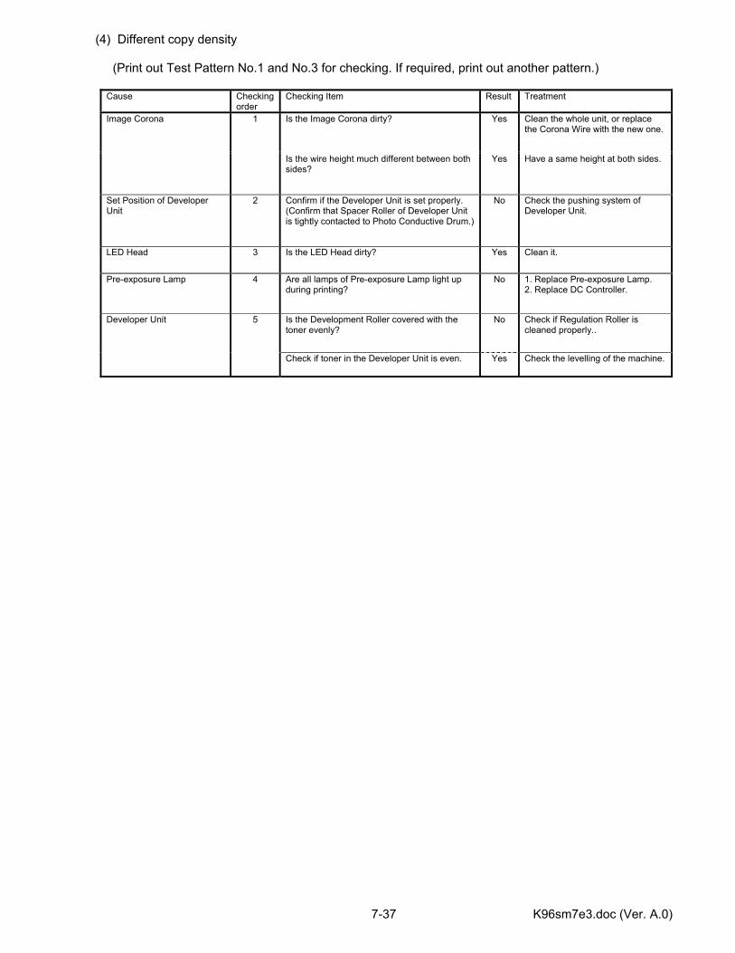
K96sm7e3.doc (Ver. A.0) 7-37
(4) Different copy density (Print out Test Pattern No.1 and No.3 for checking. If required, print out another pattern.)
Cause Checking order
Checking Item Result Treatment
Is the Image Corona dirty? Yes Clean the whole unit, or replace the Corona Wire with the new one.
Image Corona 1
Is the wire height much different between both sides?
Yes Have a same height at both sides.
Set Position of Developer Unit
2 Confirm if the Developer Unit is set properly. (Confirm that Spacer Roller of Developer Unit is tightly contacted to Photo Conductive Drum.)
No Check the pushing system of Developer Unit.
LED Head 3 Is the LED Head dirty? Yes Clean it.
Pre-exposure Lamp 4 Are all lamps of Pre-exposure Lamp light up during printing?
No 1. Replace Pre-exposure Lamp. 2. Replace DC Controller.
Is the Development Roller covered with the toner evenly?
No Check if Regulation Roller is cleaned properly..
Developer Unit 5
Check if toner in the Developer Unit is even. Yes Check the levelling of the machine.
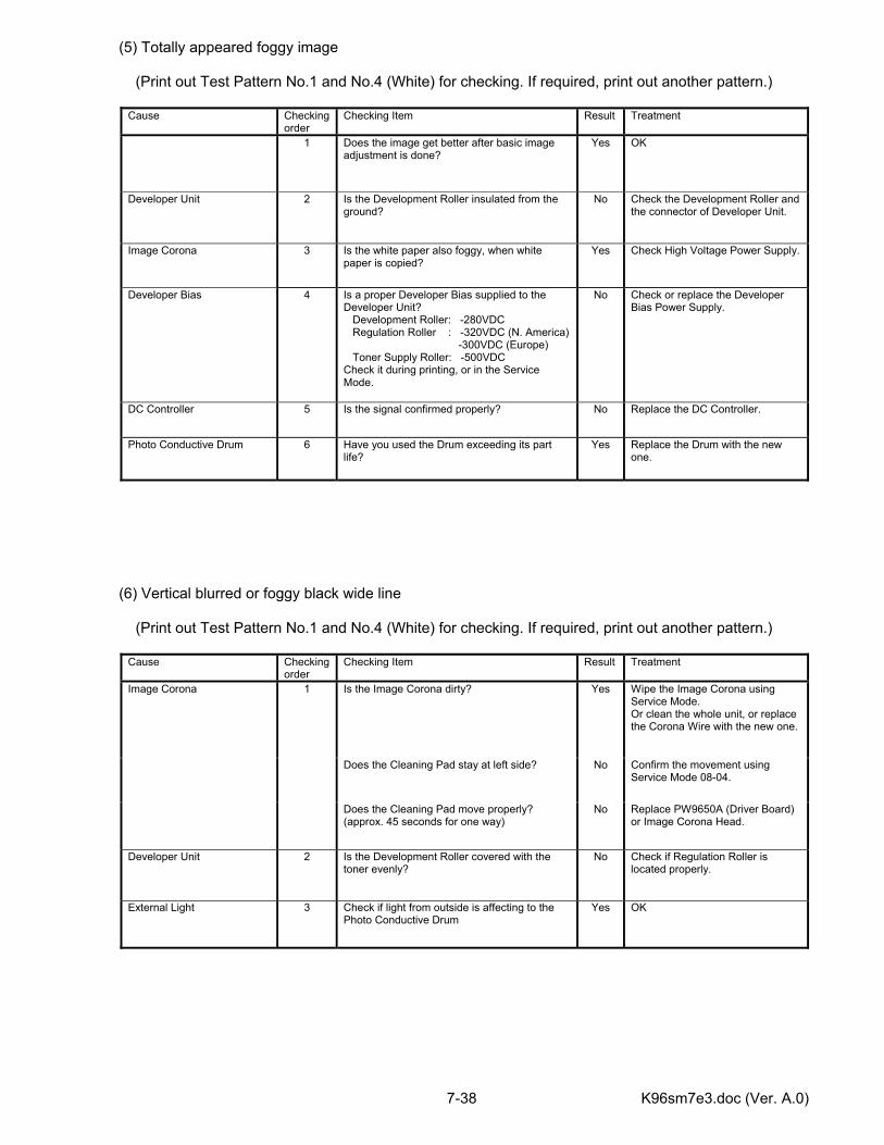
K96sm7e3.doc (Ver. A.0) 7-38
(5) Totally appeared foggy image (Print out Test Pattern No.1 and No.4 (White) for checking. If required, print out another pattern.)
Cause Checking order
Checking Item Result Treatment
1 Does the image get better after basic image adjustment is done?
Yes OK
Developer Unit 2 Is the Development Roller insulated from the ground?
No Check the Development Roller and the connector of Developer Unit.
Image Corona 3 Is the white paper also foggy, when white paper is copied?
Yes Check High Voltage Power Supply.
Developer Bias 4 Is a proper Developer Bias supplied to the Developer Unit? Development Roller: -280VDC Regulation Roller : -320VDC (N. America) -300VDC (Europe) Toner Supply Roller: -500VDC Check it during printing, or in the Service Mode.
No Check or replace the Developer Bias Power Supply.
DC Controller 5 Is the signal confirmed properly? No Replace the DC Controller.
Photo Conductive Drum 6 Have you used the Drum exceeding its part life?
Yes Replace the Drum with the new one.
(6) Vertical blurred or foggy black wide line (Print out Test Pattern No.1 and No.4 (White) for checking. If required, print out another pattern.)
Cause Checking order
Checking Item Result Treatment
Is the Image Corona dirty? Yes Wipe the Image Corona using Service Mode. Or clean the whole unit, or replace the Corona Wire with the new one.
Does the Cleaning Pad stay at left side? No Confirm the movement using Service Mode 08-04.
Image Corona 1
Does the Cleaning Pad move properly? (approx. 45 seconds for one way)
No Replace PW9650A (Driver Board) or Image Corona Head.
Developer Unit 2 Is the Development Roller covered with the toner evenly?
No Check if Regulation Roller is located properly.
External Light 3 Check if light from outside is affecting to the Photo Conductive Drum
Yes OK
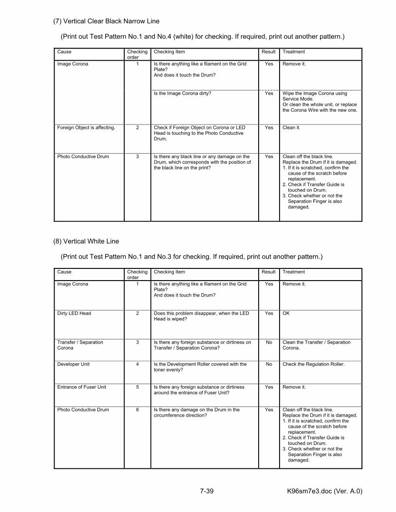
K96sm7e3.doc (Ver. A.0) 7-39
(7) Vertical Clear Black Narrow Line (Print out Test Pattern No.1 and No.4 (white) for checking. If required, print out another pattern.)
Cause Checking order
Checking Item Result Treatment
Is there anything like a filament on the Grid Plate? And does it touch the Drum?
Yes Remove it. Image Corona 1
Is the Image Corona dirty? Yes Wipe the Image Corona using Service Mode. Or clean the whole unit, or replace the Corona Wire with the new one.
Foreign Object is affecting. 2 Check if Foreign Object on Corona or LED Head is touching to the Photo Conductive Drum.
Yes Clean it.
Photo Conductive Drum 3 Is there any black line or any damage on the Drum, which corresponds with the position of the black line on the print?
Yes Clean off the black line. Replace the Drum if it is damaged. 1. If it is scratched, confirm the cause of the scratch before replacement. 2. Check if Transfer Guide is touched on Drum. 3. Check whether or not the Separation Finger is also damaged.
(8) Vertical White Line (Print out Test Pattern No.1 and No.3 for checking. If required, print out another pattern.)
Cause Checking order
Checking Item Result Treatment
Image Corona 1 Is there anything like a filament on the Grid Plate? And does it touch the Drum?
Yes Remove it.
Dirty LED Head 2 Does this problem disappear, when the LED Head is wiped?
Yes OK
Transfer / Separation Corona
3 Is there any foreign substance or dirtiness on Transfer / Separation Corona?
No Clean the Transfer / Separation Corona.
Developer Unit 4 Is the Development Roller covered with the toner evenly?
No Check the Regulation Roller.
Entrance of Fuser Unit 5 Is there any foreign substance or dirtiness around the entrance of Fuser Unit?
Yes Remove it.
Photo Conductive Drum 6 Is there any damage on the Drum in the circumference direction?
Yes Clean off the black line. Replace the Drum if it is damaged. 1. If it is scratched, confirm the cause of the scratch before replacement. 2. Check if Transfer Guide is touched on Drum. 3. Check whether or not the Separation Finger is also damaged.
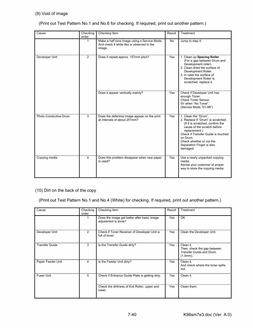
K96sm7e3.doc (Ver. A.0) 7-40
(9) Void of image (Print out Test Pattern No.1 and No.6 for checking. If required, print out another pattern.)
Cause Checking order
Checking Item Result Treatment
1 Make a half tone image using a Service Mode. And check if white like is observed in the image.
No Jump to step 4.
Does it repeat approx. 157mm pitch? Yes 1. Clean up Spacing Roller. (For a gap between Drum and Development roller) 2. Clean dried the surface of Development Roller. 3. In case the surface of Development Roller is scratched, replace it.
Developer Unit 2
Does it appear vertically mainly? Yes Check if Developer Unit has enough Toner. Check Toner Sensor. 0V when “No Toner”. (Service Mode “01-0B”)
Photo Conductive Drum
3 Does the defective image appear on the print at intervals of about 251mm?
Yes 1. Clean the “Drum”. 2. Replace if “Drum” is scratched. (If it is scratched, confirm the cause of the scratch before replacement.) Check if Transfer Guide is touched on Drum. Check whether or not the Separation Finger is also damaged.
Copying media 4 Does this problem disappear when new paper is used?
Yes Use a newly unpacked copying media. Advise your customer of proper way to store the copying media.
(10) Dirt on the back of the copy (Print out Test Pattern No.1 and No.4 (White) for checking. If required, print out another pattern.)
Cause Checking order
Checking Item Result Treatment
1 Does the image get better after basic image adjustment is done?
Yes OK
Developer Unit 2 Check if Toner Receiver of Developer Unit is full of toner.
Yes Clean the Developer Unit.
Transfer Guide 3 Is the Transfer Guide dirty? Yes Clean it. Then, check the gap between Transfer Guide and Drum. (1.0mm).
Paper Feeder Unit 4 Is the Feeder Unit dirty? Yes Clean it. And check where the toner spills out.
Check if Entrance Guide Plate is getting dirty. Yes Clean it. Fuser Unit 5
Check the dirtiness of Exit Roller, upper and lower.
Yes Clean them.
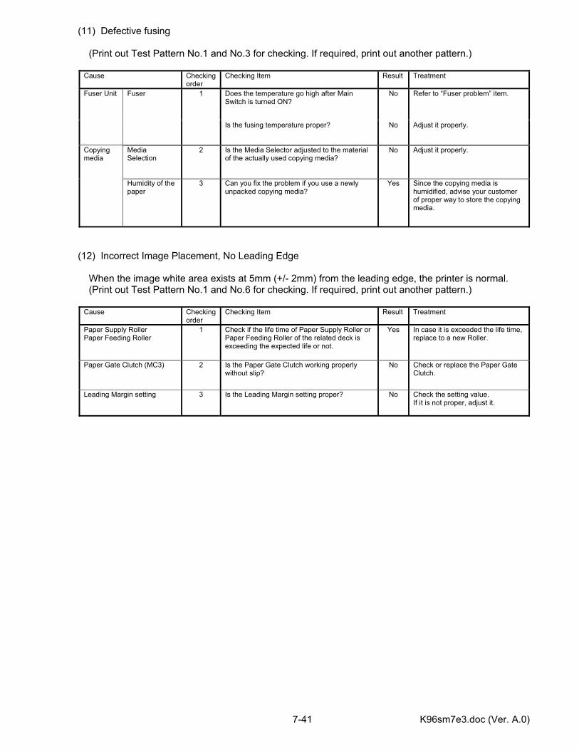
K96sm7e3.doc (Ver. A.0) 7-41
(11) Defective fusing (Print out Test Pattern No.1 and No.3 for checking. If required, print out another pattern.)
Cause Checking order
Checking Item Result Treatment
Does the temperature go high after Main Switch is turned ON?
No Refer to “Fuser problem” item. Fuser Unit Fuser 1
Is the fusing temperature proper? No Adjust it properly.
Media Selection
2 Is the Media Selector adjusted to the material of the actually used copying media?
No Adjust it properly. Copying media
Humidity of the paper
3 Can you fix the problem if you use a newly unpacked copying media?
Yes Since the copying media is humidified, advise your customer of proper way to store the copying media.
(12) Incorrect Image Placement, No Leading Edge When the image white area exists at 5mm (+/- 2mm) from the leading edge, the printer is normal. (Print out Test Pattern No.1 and No.6 for checking. If required, print out another pattern.)
Cause Checking order
Checking Item Result Treatment
Paper Supply Roller Paper Feeding Roller
1 Check if the life time of Paper Supply Roller or Paper Feeding Roller of the related deck is exceeding the expected life or not.
Yes In case it is exceeded the life time, replace to a new Roller.
Paper Gate Clutch (MC3) 2 Is the Paper Gate Clutch working properly without slip?
No Check or replace the Paper Gate Clutch.
Leading Margin setting 3 Is the Leading Margin setting proper? No Check the setting value. If it is not proper, adjust it.
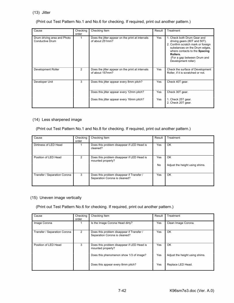
K96sm7e3.doc (Ver. A.0) 7-42
(13) Jitter (Print out Test Pattern No.1 and No.6 for checking. If required, print out another pattern.)
Cause Checking order
Checking Item Result Treatment
Drum driving area and Photo Conductive Drum
1 Does the jitter appear on the print at intervals of about 251mm?
Yes 1. Check both Drum Gear and driving gears (80T and 50T). 2. Confirm scratch mark or foreign substances on the Drum edges, where contacts to the Spacing Rollers. (For a gap between Drum and Development roller)
Development Roller 2 Does the jitter appear on the print at intervals of about 157mm?
Yes Check the surface of Development Roller, if it is scratched or not.
Does this jitter appear every 8mm pitch? Yes Check 40T gear.
Does this jitter appear every 12mm pitch? Yes Check 30T gear.
Developer Unit 3
Does this jitter appear every 16mm pitch? Yes 1. Check 25T gear. 2. Check 20T gear.
(14) Less sharpened image (Print out Test Pattern No.1 and No.8 for checking. If required, print out another pattern.)
Cause Checking order
Checking Item Result Treatment
Dirtiness of LED Head 1 Does this problem disappear if LED Head is cleaned?
Yes OK
Yes OK Position of LED Head 2 Does this problem disappear if LED Head is mounted properly?
No Adjust the height using shims.
Transfer / Separation Corona 3 Does this problem disappear if Transfer / Separation Corona is cleaned?
Yes OK
(15) Uneven image vertically (Print out Test Pattern No.6 for checking. If required, print out another pattern.)
Cause Checking order
Checking Item Result Treatment
Image Corona 1 Is the Image Corona Head dirty? Yes Clean Image Corona.
Transfer / Separation Corona 2 Does this problem disappear if Transfer / Separation Corona is cleaned?
Yes
OK
Does this problem disappear if LED Head is mounted properly?
Yes OK
Does this phenomenon show 1/3 of image? Yes Adjust the height using shims.
Position of LED Head 3
Does this appear every 8mm pitch? Yes Replace LED Head.
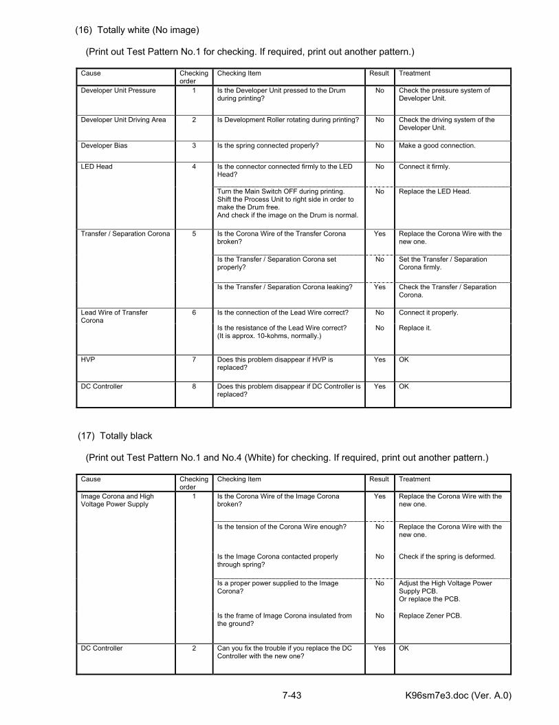
K96sm7e3.doc (Ver. A.0) 7-43
(16) Totally white (No image) (Print out Test Pattern No.1 for checking. If required, print out another pattern.)
Cause Checking order
Checking Item Result Treatment
Developer Unit Pressure 1 Is the Developer Unit pressed to the Drum during printing?
No Check the pressure system of Developer Unit.
Developer Unit Driving Area 2 Is Development Roller rotating during printing? No Check the driving system of the Developer Unit.
Developer Bias 3 Is the spring connected properly? No Make a good connection.
Is the connector connected firmly to the LED Head?
No Connect it firmly. LED Head 4
Turn the Main Switch OFF during printing. Shift the Process Unit to right side in order to make the Drum free. And check if the image on the Drum is normal.
No Replace the LED Head.
Is the Corona Wire of the Transfer Corona broken?
Yes Replace the Corona Wire with the new one.
Is the Transfer / Separation Corona set properly?
No Set the Transfer / Separation Corona firmly.
Transfer / Separation Corona 5
Is the Transfer / Separation Corona leaking? Yes Check the Transfer / Separation Corona.
Is the connection of the Lead Wire correct? No Connect it properly. Lead Wire of Transfer Corona
6
Is the resistance of the Lead Wire correct? (It is approx. 10-kohms, normally.)
No Replace it.
HVP 7 Does this problem disappear if HVP is replaced?
Yes OK
DC Controller 8 Does this problem disappear if DC Controller is replaced?
Yes OK
(17) Totally black (Print out Test Pattern No.1 and No.4 (White) for checking. If required, print out another pattern.)
Cause Checking order
Checking Item Result Treatment
Is the Corona Wire of the Image Corona broken?
Yes Replace the Corona Wire with the new one.
Is the tension of the Corona Wire enough? No Replace the Corona Wire with the new one.
Is the Image Corona contacted properly through spring?
No Check if the spring is deformed.
Is a proper power supplied to the Image Corona?
No Adjust the High Voltage Power Supply PCB. Or replace the PCB.
Image Corona and High Voltage Power Supply
1
Is the frame of Image Corona insulated from the ground?
No Replace Zener PCB.
DC Controller 2 Can you fix the trouble if you replace the DC Controller with the new one?
Yes OK
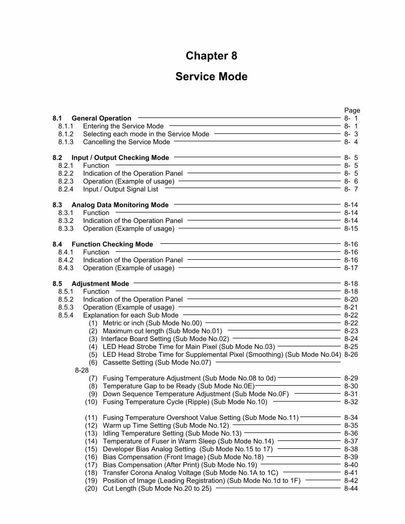
Chapter 8
Service Mode Page 8.1 General Operation 8- 1 8.1.1 Entering the Service Mode 8- 1 8.1.2 Selecting each mode in the Service Mode 8- 3 8.1.3 Cancelling the Service Mode 8- 4 8.2 Input / Output Checking Mode 8- 5 8.2.1 Function 8- 5 8.2.2 Indication of the Operation Panel 8- 5 8.2.3 Operation (Example of usage) 8- 6 8.2.4 Input / Output Signal List 8- 7 8.3 Analog Data Monitoring Mode 8-14 8.3.1 Function 8-14 8.3.2 Indication of the Operation Panel 8-14 8.3.3 Operation (Example of usage) 8-15 8.4 Function Checking Mode 8-16 8.4.1 Function 8-16 8.4.2 Indication of the Operation Panel 8-16 8.4.3 Operation (Example of usage) 8-17 8.5 Adjustment Mode 8-18 8.5.1 Function 8-18 8.5.2 Indication of the Operation Panel 8-20 8.5.3 Operation (Example of usage) 8-21 8.5.4 Explanation for each Sub Mode 8-22 (1) Metric or inch (Sub Mode No.00) 8-22 (2) Maximum cut length (Sub Mode No.01) 8-23 (3) Interface Board Setting (Sub Mode No.02) 8-24 (4) LED Head Strobe Time for Main Pixel (Sub Mode No.03) 8-25 (5) LED Head Strobe Time for Supplemental Pixel (Smoothing) (Sub Mode No.04) 8-26 (6) Cassette Setting (Sub Mode No.07) 8-28 (7) Fusing Temperature Adjustment (Sub Mode No.08 to 0d) 8-29 (8) Temperature Gap to be Ready (Sub Mode No.0E) 8-30 (9) Down Sequence Temperature Adjustment (Sub Mode No.0F) 8-31 (10) Fusing Temperature Cycle (Ripple) (Sub Mode No.10) 8-32 (11) Fusing Temperature Overshoot Value Setting (Sub Mode No.11) 8-34 (12) Warm up Time Setting (Sub Mode No.12) 8-35 (13) Idling Temperature Setting (Sub Mode No.13) 8-36 (14) Temperature of Fuser in Warm Sleep (Sub Mode No.14) 8-37 (15) Developer Bias Analog Setting (Sub Mode No.15 to 17) 8-38 (16) Bias Compensation (Front Image) (Sub Mode No.18) 8-39 (17) Bias Compensation (After Print) (Sub Mode No.19) 8-40 (18) Transfer Corona Analog Voltage (Sub Mode No.1A to 1C) 8-41 (19) Position of Image (Leading Registration) (Sub Mode No.1d to 1F) 8-42 (20) Cut Length (Sub Mode No.20 to 25) 8-44
(21) White Margin of Trailing Image (Sub Mode No.26, 27) 8-46 (22) Amount of Side Margins (Sub Mode No.28) 8-47 (23) Transfer Corona ON Timing (Sub Mode No.29) 8-48 (24) Transfer Corona OFF Timing (Sub Mode No.2A) 8-49 (25) AC Corona OFF Timing (Sub Mode No.2b to 2d) 8-50 (26) Dehumidify Heater Setting (Sub Mode No.2E) 8-51 (27) Unit of Counter (Sub Mode No.2F) 8-52 (28) Key Card Setting (Sub Mode No.30) 8-53 (29) Optional Instrument Setting (Sub Mode No.31) 8-54 (30) Number of Roll Deck (Sub Mode No.32) 8-55 (31) User Mode Function (Sub Mode No.33) 8-56 (32) Main Motor Speed (Sub Mode No.34) 8-57 (33) Paper Feeding Motor Speed (Sub Mode No.35 to 37) 8-58 (34) Fuser Motor speed (Sub Mode No.38 to 3A) 8-59 (35) Fuser Motor 2nd Speed Switching Timing (Sub Mode No.3b to 3d) 8-60 (36) Fuser Motor 2nd Speed (Sub Mode No.3E to 40) 8-61 (37) Fuser Motor 3rd Speed Switching Timing (Sub Mode No.41 to 43) 8-62 (38) Fuser Motor 3rd Speed (Sub Mode No.44 to r6) 8-63 (39) Toner Supply Volume Adjustment (Sub Mode No.47) 8-64 (40) Down Sequence Shift Time caused by Toner (Sub Mode No.48) 8-65 (41) Register Roller Adjustment Volume (Cassette) (Sub Mode No.49) 8-66 (42) Transfer Corona ON Timing (Cassette) (Sub Mode No.4A) 8-67 (43) Transfer Corona OFF Timing (Cassette) (Sub Mode No.4b) 8-68 8.6 Running Mode 8-69 8.6.1 Function 8-69 8.6.2 Indication of the Operation Panel 8-69 8.6.3 Operation 8-70 8.7 Error Check Masking Mode 8-71 8.7.1 Function 8-71 8.7.2 Indication of the Operation Panel 8-72 8.7.3 Operation (Example of usage) 8-73 8.8 Test Print Mode 8-74 8.8.1 Function 8-74 8.8.2 Indication of the Operation Panel 8-74 8.8.3 Operation 8-75 8.9 Factory Adjustment Mode 8-86 8.9.1 Function 8-86 8.9.2 Indication of the Operation Panel 8-87 8.9.3 Operation (Example of usage) 8-88 8.9.4 Internal Counter Adjustment (Sub Mode 07 & 08) 8-89 8.10 Ram Clear Mode 8-92 8.10.1 Function 8-92 8.10.2 Operation 8-92
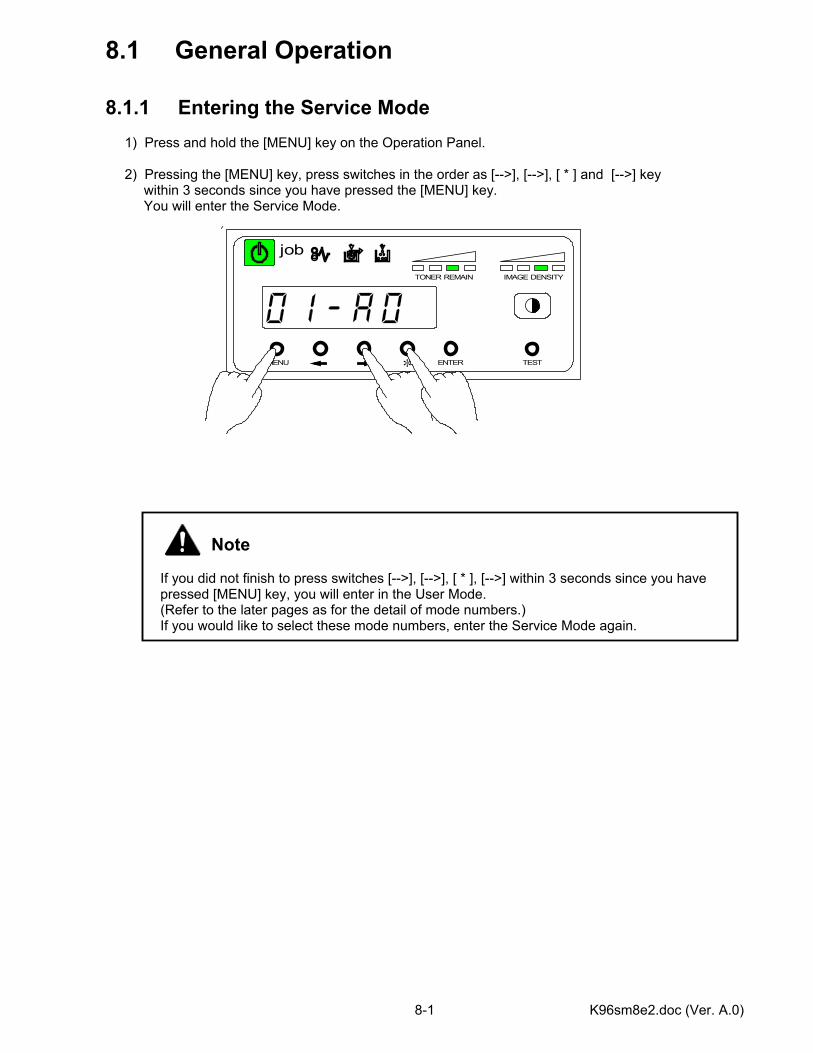
K96sm8e2.doc (Ver. A.0) 8-1
8.1 General Operation 8.1.1 Entering the Service Mode 1) Press and hold the [MENU] key on the Operation Panel. 2) Pressing the [MENU] key, press switches in the order as [-->], [-->], [ * ] and [-->] key within 3 seconds since you have pressed the [MENU] key. You will enter the Service Mode.
Note If you did not finish to press switches [-->], [-->], [ * ], [-->] within 3 seconds since you have pressed [MENU] key, you will enter in the User Mode. (Refer to the later pages as for the detail of mode numbers.) If you would like to select these mode numbers, enter the Service Mode again.
MENU ENTER TEST
TONER REMAIN IMAGE DENSITY
job
*
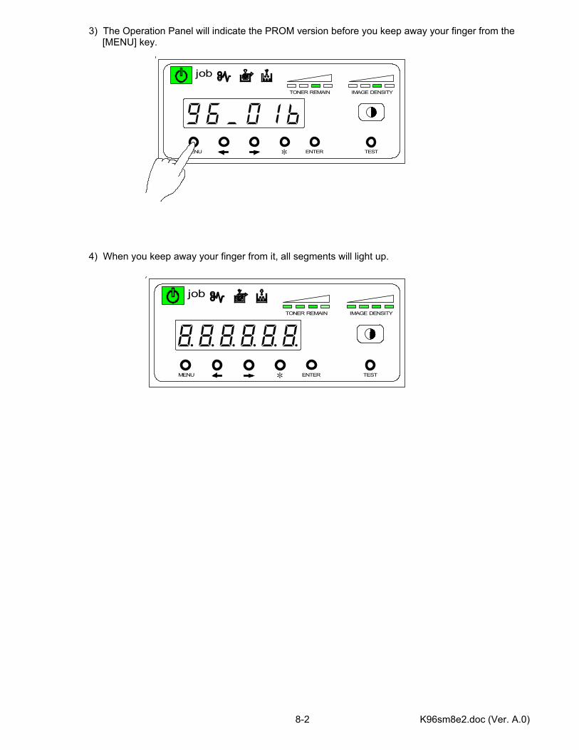
K96sm8e2.doc (Ver. A.0) 8-2
3) The Operation Panel will indicate the PROM version before you keep away your finger from the [MENU] key. 4) When you keep away your finger from it, all segments will light up.
MENU ENTER TEST
TONER REMAIN IMAGE DENSITY
job
*
MENU ENTER TEST
TONER REMAIN IMAGE DENSITY
job
*
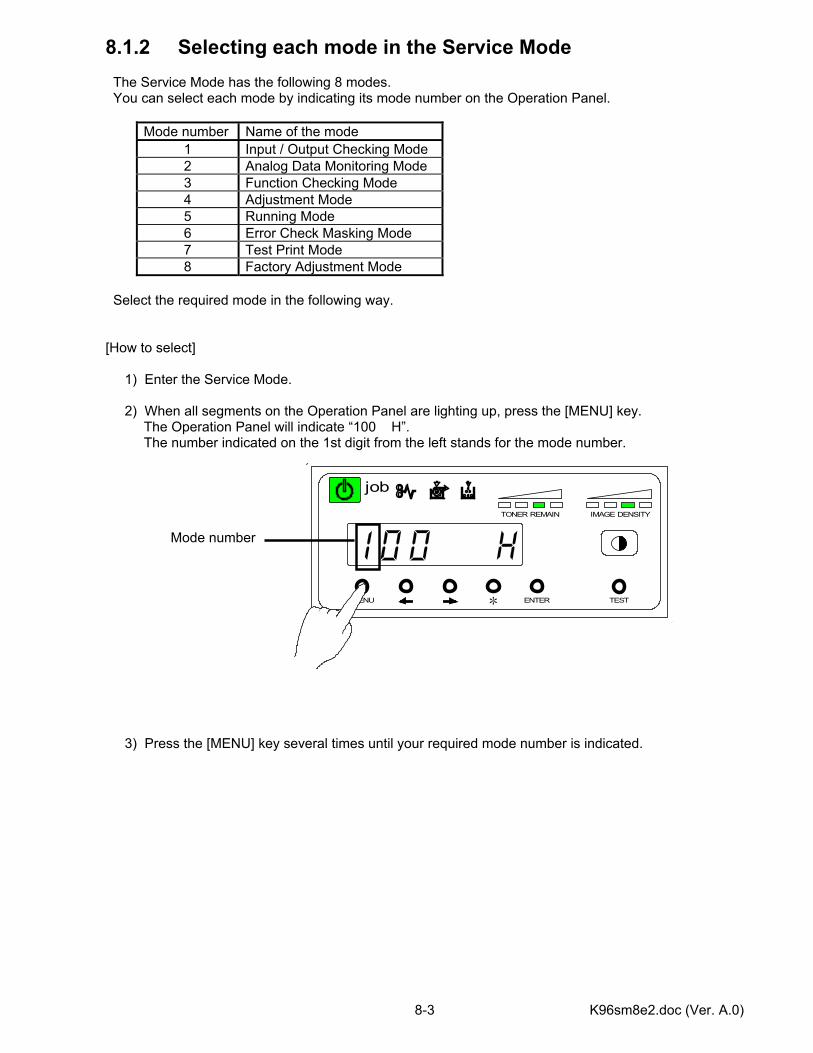
K96sm8e2.doc (Ver. A.0) 8-3
8.1.2 Selecting each mode in the Service Mode The Service Mode has the following 8 modes. You can select each mode by indicating its mode number on the Operation Panel.
Mode number Name of the mode 1 Input / Output Checking Mode 2 Analog Data Monitoring Mode 3 Function Checking Mode 4 Adjustment Mode 5 Running Mode 6 Error Check Masking Mode 7 Test Print Mode 8 Factory Adjustment Mode
Select the required mode in the following way. [How to select] 1) Enter the Service Mode. 2) When all segments on the Operation Panel are lighting up, press the [MENU] key. The Operation Panel will indicate “100 H”. The number indicated on the 1st digit from the left stands for the mode number. Mode number 3) Press the [MENU] key several times until your required mode number is indicated.
MENU ENTER TEST
TONER REMAIN IMAGE DENSITY
job
*
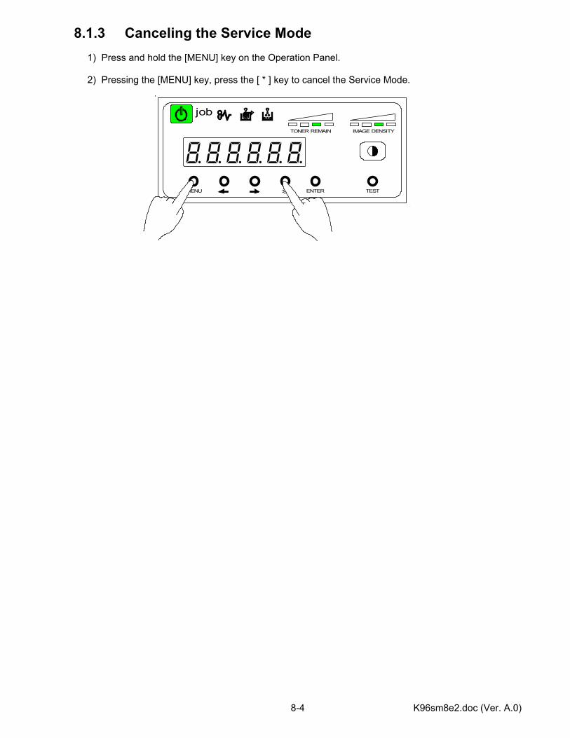
K96sm8e2.doc (Ver. A.0) 8-4
8.1.3 Canceling the Service Mode 1) Press and hold the [MENU] key on the Operation Panel. 2) Pressing the [MENU] key, press the [ * ] key to cancel the Service Mode.
MENU ENTER TEST
TONER REMAIN IMAGE DENSITY
job
*
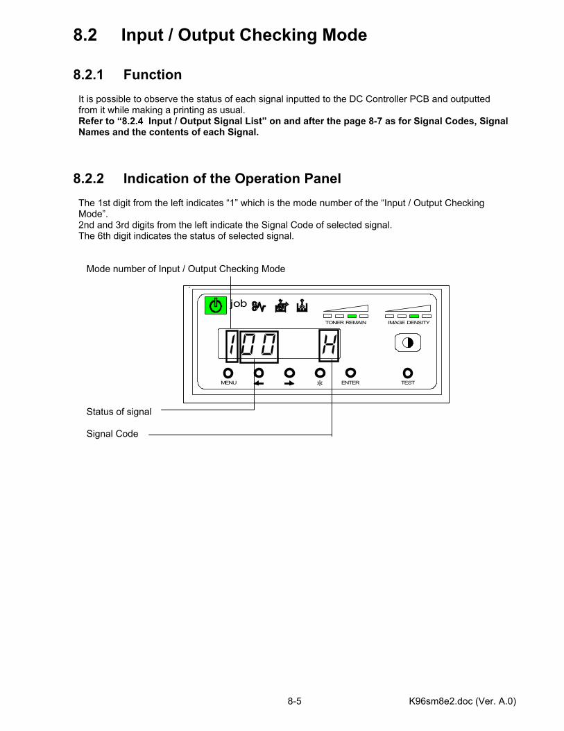
K96sm8e2.doc (Ver. A.0) 8-5
MENU ENTER TEST
TONER REMAIN IMAGE DENSITY
job
*
8.2 Input / Output Checking Mode 8.2.1 Function It is possible to observe the status of each signal inputted to the DC Controller PCB and outputted from it while making a printing as usual. Refer to “8.2.4 Input / Output Signal List” on and after the page 8-7 as for Signal Codes, Signal Names and the contents of each Signal. 8.2.2 Indication of the Operation Panel The 1st digit from the left indicates “1” which is the mode number of the “Input / Output Checking Mode”. 2nd and 3rd digits from the left indicate the Signal Code of selected signal. The 6th digit indicates the status of selected signal. Mode number of Input / Output Checking Mode Status of signal Signal Code
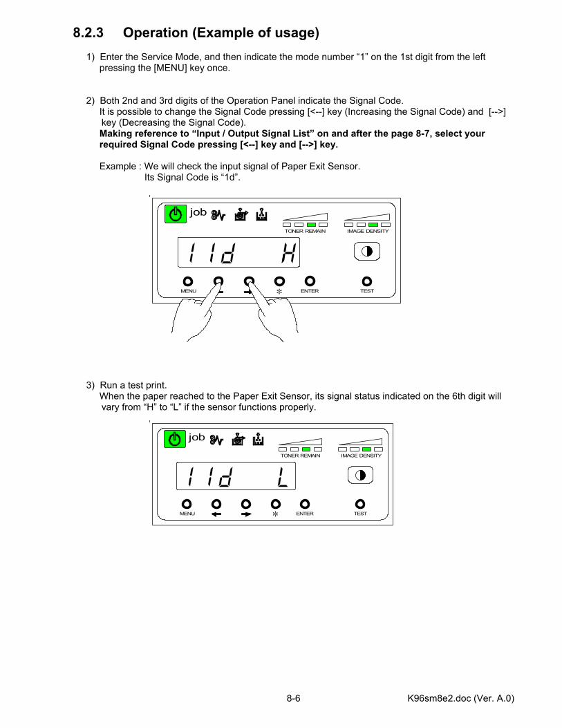
K96sm8e2.doc (Ver. A.0) 8-6
8.2.3 Operation (Example of usage) 1) Enter the Service Mode, and then indicate the mode number “1” on the 1st digit from the left pressing the [MENU] key once. 2) Both 2nd and 3rd digits of the Operation Panel indicate the Signal Code. It is possible to change the Signal Code pressing [<--] key (Increasing the Signal Code) and [-->]
key (Decreasing the Signal Code). Making reference to “Input / Output Signal List” on and after the page 8-7, select your required Signal Code pressing [<--] key and [-->] key. Example : We will check the input signal of Paper Exit Sensor. Its Signal Code is “1d”. 3) Run a test print. When the paper reached to the Paper Exit Sensor, its signal status indicated on the 6th digit will
vary from “H” to “L” if the sensor functions properly.
MENU ENTER TEST
TONER REMAIN IMAGE DENSITY
job
*
MENU ENTER TEST
TONER REMAIN IMAGE DENSITY
job
*
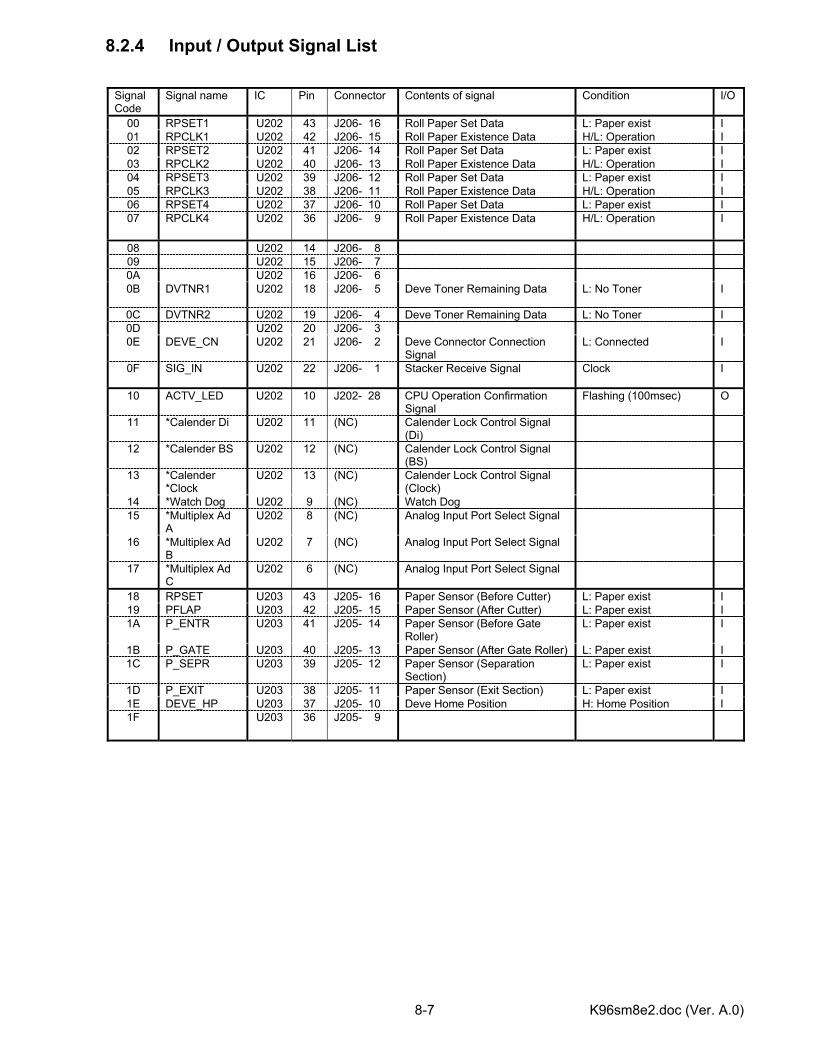
K96sm8e2.doc (Ver. A.0) 8-7
8.2.4 Input / Output Signal List
Signal Code
Signal name IC Pin Connector Contents of signal Condition I/O
00 RPSET1 U202 43 J206- 16 Roll Paper Set Data L: Paper exist I 01 RPCLK1 U202 42 J206- 15 Roll Paper Existence Data H/L: Operation I 02 RPSET2 U202 41 J206- 14 Roll Paper Set Data L: Paper exist I 03 RPCLK2 U202 40 J206- 13 Roll Paper Existence Data H/L: Operation I 04 RPSET3 U202 39 J206- 12 Roll Paper Set Data L: Paper exist I 05 RPCLK3 U202 38 J206- 11 Roll Paper Existence Data H/L: Operation I 06 RPSET4 U202 37 J206- 10 Roll Paper Set Data L: Paper exist I 07 RPCLK4 U202 36 J206- 9 Roll Paper Existence Data H/L: Operation I
08 U202 14 J206- 8 09 U202 15 J206- 7 0A U202 16 J206- 6 0B DVTNR1 U202 18 J206- 5 Deve Toner Remaining Data L: No Toner I
0C DVTNR2 U202 19 J206- 4 Deve Toner Remaining Data L: No Toner I 0D U202 20 J206- 3 0E DEVE_CN U202 21 J206- 2 Deve Connector Connection
Signal L: Connected I
0F SIG_IN U202 22 J206- 1 Stacker Receive Signal Clock I
10 ACTV_LED U202 10 J202- 28 CPU Operation Confirmation Signal
Flashing (100msec) O
11 *Calender Di U202 11 (NC) Calender Lock Control Signal (Di)
12 *Calender BS U202 12 (NC) Calender Lock Control Signal (BS)
13 *Calender *Clock
U202 13 (NC) Calender Lock Control Signal (Clock)
14 *Watch Dog U202 9 (NC) Watch Dog 15 *Multiplex Ad
A U202 8 (NC) Analog Input Port Select Signal
16 *Multiplex Ad B
U202 7 (NC) Analog Input Port Select Signal
17 *Multiplex Ad C
U202 6 (NC) Analog Input Port Select Signal
18 RPSET U203 43 J205- 16 Paper Sensor (Before Cutter) L: Paper exist I 19 PFLAP U203 42 J205- 15 Paper Sensor (After Cutter) L: Paper exist I 1A P_ENTR U203 41 J205- 14 Paper Sensor (Before Gate
Roller) L: Paper exist I
1B P_GATE U203 40 J205- 13 Paper Sensor (After Gate Roller) L: Paper exist I 1C P_SEPR U203 39 J205- 12 Paper Sensor (Separation
Section) L: Paper exist I
1D P_EXIT U203 38 J205- 11 Paper Sensor (Exit Section) L: Paper exist I 1E DEVE_HP U203 37 J205- 10 Deve Home Position H: Home Position I 1F U203 36 J205- 9
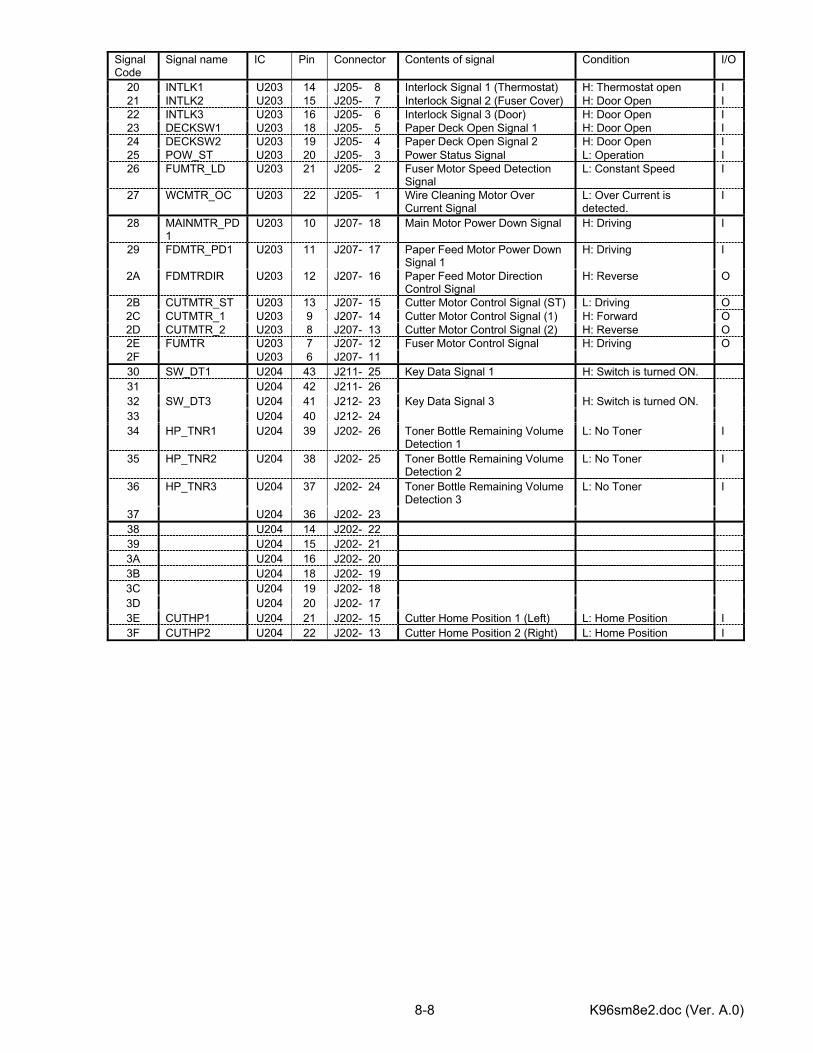
K96sm8e2.doc (Ver. A.0) 8-8
Signal Code
Signal name IC Pin Connector Contents of signal Condition I/O
20 INTLK1 U203 14 J205- 8 Interlock Signal 1 (Thermostat) H: Thermostat open I 21 INTLK2 U203 15 J205- 7 Interlock Signal 2 (Fuser Cover) H: Door Open I 22 INTLK3 U203 16 J205- 6 Interlock Signal 3 (Door) H: Door Open I 23 DECKSW1 U203 18 J205- 5 Paper Deck Open Signal 1 H: Door Open I 24 DECKSW2 U203 19 J205- 4 Paper Deck Open Signal 2 H: Door Open I 25 POW_ST U203 20 J205- 3 Power Status Signal L: Operation I 26 FUMTR_LD U203 21 J205- 2 Fuser Motor Speed Detection
Signal L: Constant Speed I
27 WCMTR_OC U203 22 J205- 1 Wire Cleaning Motor Over Current Signal
L: Over Current is detected.
I
28 MAINMTR_PD1
U203 10 J207- 18 Main Motor Power Down Signal H: Driving I
29 FDMTR_PD1 U203 11 J207- 17 Paper Feed Motor Power Down Signal 1
H: Driving I
2A FDMTRDIR U203 12 J207- 16 Paper Feed Motor Direction Control Signal
H: Reverse O
2B CUTMTR_ST U203 13 J207- 15 Cutter Motor Control Signal (ST) L: Driving O 2C CUTMTR_1 U203 9 J207- 14 Cutter Motor Control Signal (1) H: Forward O 2D CUTMTR_2 U203 8 J207- 13 Cutter Motor Control Signal (2) H: Reverse O 2E FUMTR U203 7 J207- 12 Fuser Motor Control Signal H: Driving O 2F U203 6 J207- 11 30 SW_DT1 U204 43 J211- 25 Key Data Signal 1 H: Switch is turned ON. 31 U204 42 J211- 26 32 SW_DT3 U204 41 J212- 23 Key Data Signal 3 H: Switch is turned ON. 33 U204 40 J212- 24 34 HP_TNR1 U204 39 J202- 26 Toner Bottle Remaining Volume
Detection 1 L: No Toner I
35 HP_TNR2 U204 38 J202- 25 Toner Bottle Remaining Volume Detection 2
L: No Toner I
36 HP_TNR3 U204 37 J202- 24 Toner Bottle Remaining Volume Detection 3
L: No Toner I
37 U204 36 J202- 23 38 U204 14 J202- 22 39 U204 15 J202- 21 3A U204 16 J202- 20 3B U204 18 J202- 19 3C U204 19 J202- 18 3D U204 20 J202- 17 3E CUTHP1 U204 21 J202- 15 Cutter Home Position 1 (Left) L: Home Position I 3F CUTHP2 U204 22 J202- 13 Cutter Home Position 2 (Right) L: Home Position I
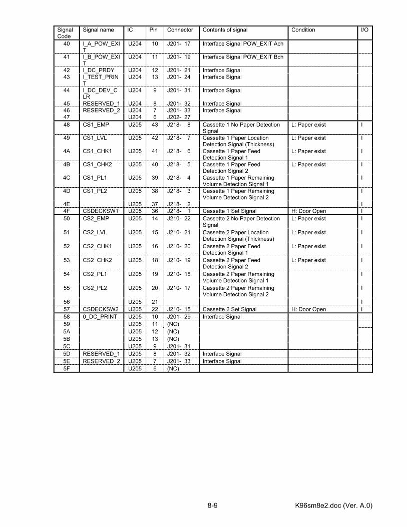
K96sm8e2.doc (Ver. A.0) 8-9
Signal Code
Signal name IC Pin Connector Contents of signal Condition I/O
40 I_A_POW_EXIT
U204 10 J201- 17 Interface Signal POW_EXIT Ach
41 I_B_POW_EXIT
U204 11 J201- 19 Interface Signal POW_EXIT Bch
42 I_DC_PRDY U204 12 J201- 21 Interface Signal 43 I_TEST_PRIN
T U204 13 J201- 24 Interface Signal
44 I_DC_DEV_CLR
U204 9 J201- 31 Interface Signal
45 RESERVED_1 U204 8 J201- 32 Interface Signal 46 RESERVED_2 U204 7 J201- 33 Interface Signal 47 U204 6 J202- 27 48 CS1_EMP U205 43 J218- 8 Cassette 1 No Paper Detection
Signal L: Paper exist I
49 CS1_LVL U205 42 J218- 7 Cassette 1 Paper Location Detection Signal (Thickness)
L: Paper exist I
4A CS1_CHK1 U205 41 J218- 6 Cassette 1 Paper Feed Detection Signal 1
L: Paper exist I
4B CS1_CHK2 U205 40 J218- 5 Cassette 1 Paper Feed Detection Signal 2
L: Paper exist I
4C CS1_PL1 U205 39 J218- 4 Cassette 1 Paper Remaining Volume Detection Signal 1
I
4D CS1_PL2 U205 38 J218- 3 Cassette 1 Paper Remaining Volume Detection Signal 2
I
4E U205 37 J218- 2 I 4F CSDECKSW1 U205 36 J218- 1 Cassette 1 Set Signal H: Door Open I 50 CS2_EMP U205 14 J210- 22 Cassette 2 No Paper Detection
Signal L: Paper exist I
51 CS2_LVL U205 15 J210- 21 Cassette 2 Paper Location Detection Signal (Thickness)
L: Paper exist I
52 CS2_CHK1 U205 16 J210- 20 Cassette 2 Paper Feed Detection Signal 1
L: Paper exist I
53 CS2_CHK2 U205 18 J210- 19 Cassette 2 Paper Feed Detection Signal 2
L: Paper exist I
54 CS2_PL1 U205 19 J210- 18 Cassette 2 Paper Remaining Volume Detection Signal 1
I
55 CS2_PL2 U205 20 J210- 17 Cassette 2 Paper Remaining Volume Detection Signal 2
I
56 U205 21 I 57 CSDECKSW2 U205 22 J210- 15 Cassette 2 Set Signal H: Door Open I 58 0_DC_PRINT U205 10 J201- 29 Interface Signal 59 U205 11 (NC) 5A U205 12 (NC) 5B U205 13 (NC) 5C U205 9 J201- 31 5D RESERVED_1 U205 8 J201- 32 Interface Signal 5E RESERVED_2 U205 7 J201- 33 Interface Signal 5F U205 6 (NC)
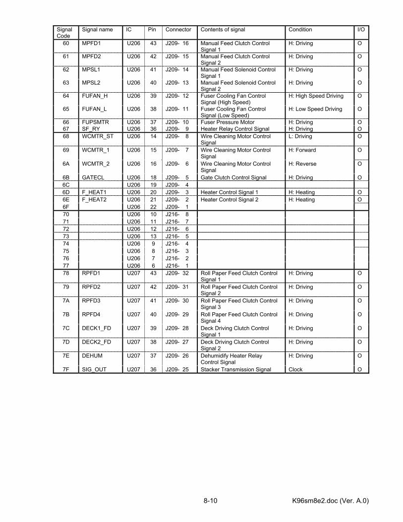
K96sm8e2.doc (Ver. A.0) 8-10
Signal Code
Signal name IC Pin Connector Contents of signal Condition I/O
60 MPFD1 U206 43 J209- 16 Manual Feed Clutch Control Signal 1
H: Driving O
61 MPFD2 U206 42 J209- 15 Manual Feed Clutch Control Signal 2
H: Driving O
62 MPSL1 U206 41 J209- 14 Manual Feed Solenoid Control Signal 1
H: Driving O
63 MPSL2 U206 40 J209- 13 Manual Feed Solenoid Control Signal 2
H: Driving O
64 FUFAN_H U206 39 J209- 12 Fuser Cooling Fan Control Signal (High Speed)
H: High Speed Driving O
65 FUFAN_L U206 38 J209- 11 Fuser Cooling Fan Control Signal (Low Speed)
H: Low Speed Driving O
66 FUPSMTR U206 37 J209- 10 Fuser Pressure Motor H: Driving O 67 SF_RY U206 36 J209- 9 Heater Relay Control Signal H: Driving O 68 WCMTR_ST U206 14 J209- 8 Wire Cleaning Motor Control
Signal L: Driving O
69 WCMTR_1 U206 15 J209- 7 Wire Cleaning Motor Control Signal
H: Forward O
6A WCMTR_2 U206 16 J209- 6 Wire Cleaning Motor Control Signal
H: Reverse O
6B GATECL U206 18 J209- 5 Gate Clutch Control Signal H: Driving O 6C U206 19 J209- 4 6D F_HEAT1 U206 20 J209- 3 Heater Control Signal 1 H: Heating O 6E F_HEAT2 U206 21 J209- 2 Heater Control Signal 2 H: Heating O 6F U206 22 J209- 1 70 U206 10 J216- 8 71 U206 11 J216- 7 72 U206 12 J216- 6 73 U206 13 J216- 5 74 U206 9 J216- 4 75 U206 8 J216- 3 76 U206 7 J216- 2 77 U206 6 J216- 1 78 RPFD1 U207 43 J209- 32 Roll Paper Feed Clutch Control
Signal 1 H: Driving O
79 RPFD2 U207 42 J209- 31 Roll Paper Feed Clutch Control Signal 2
H: Driving O
7A RPFD3 U207 41 J209- 30 Roll Paper Feed Clutch Control Signal 3
H: Driving O
7B RPFD4 U207 40 J209- 29 Roll Paper Feed Clutch Control Signal 4
H: Driving O
7C DECK1_FD U207 39 J209- 28 Deck Driving Clutch Control Signal 1
H: Driving O
7D DECK2_FD U207 38 J209- 27 Deck Driving Clutch Control Signal 2
H: Driving O
7E DEHUM U207 37 J209- 26 Dehumidify Heater Relay Control Signal
H: Driving O
7F SIG_OUT U207 36 J209- 25 Stacker Transmission Signal Clock O
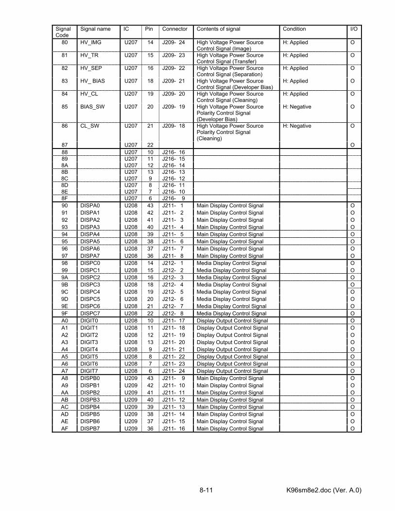
K96sm8e2.doc (Ver. A.0) 8-11
Signal Code
Signal name IC Pin Connector Contents of signal Condition I/O
80 HV_IMG U207 14 J209- 24 High Voltage Power Source Control Signal (Image)
H: Applied O
81 HV_TR U207 15 J209- 23 High Voltage Power Source Control Signal (Transfer)
H: Applied O
82 HV_SEP U207 16 J209- 22 High Voltage Power Source Control Signal (Separation)
H: Applied O
83 HV_ BIAS U207 18 J209- 21 High Voltage Power Source Control Signal (Developer Bias)
H: Applied O
84 HV_CL U207 19 J209- 20 High Voltage Power Source Control Signal (Cleaning)
H: Applied O
85 BIAS_SW U207 20 J209- 19 High Voltage Power Source Polarity Control Signal (Developer Bias)
H: Negative O
86 CL_SW U207 21 J209- 18 High Voltage Power Source Polarity Control Signal (Cleaning)
H: Negative O
87 U207 22 O 88 U207 10 J216- 16 89 U207 11 J216- 15 8A U207 12 J216- 14 8B U207 13 J216- 13 8C U207 9 J216- 12 8D U207 8 J216- 11 8E U207 7 J216- 10 8F U207 6 J216- 9 90 DISPA0 U208 43 J211- 1 Main Display Control Signal O 91 DISPA1 U208 42 J211- 2 Main Display Control Signal O 92 DISPA2 U208 41 J211- 3 Main Display Control Signal O 93 DISPA3 U208 40 J211- 4 Main Display Control Signal O 94 DISPA4 U208 39 J211- 5 Main Display Control Signal O 95 DISPA5 U208 38 J211- 6 Main Display Control Signal O 96 DISPA6 U208 37 J211- 7 Main Display Control Signal O 97 DISPA7 U208 36 J211- 8 Main Display Control Signal O 98 DISPC0 U208 14 J212- 1 Media Display Control Signal O 99 DISPC1 U208 15 J212- 2 Media Display Control Signal O 9A DISPC2 U208 16 J212- 3 Media Display Control Signal O 9B DISPC3 U208 18 J212- 4 Media Display Control Signal O 9C DISPC4 U208 19 J212- 5 Media Display Control Signal O 9D DISPC5 U208 20 J212- 6 Media Display Control Signal O 9E DISPC6 U208 21 J212- 7 Media Display Control Signal O 9F DISPC7 U208 22 J212- 8 Media Display Control Signal O A0 DIGIT0 U208 10 J211- 17 Display Output Control Signal O A1 DIGIT1 U208 11 J211- 18 Display Output Control Signal O A2 DIGIT2 U208 12 J211- 19 Display Output Control Signal O A3 DIGIT3 U208 13 J211- 20 Display Output Control Signal O A4 DIGIT4 U208 9 J211- 21 Display Output Control Signal O A5 DIGIT5 U208 8 J211- 22 Display Output Control Signal O A6 DIGIT6 U208 7 J211- 23 Display Output Control Signal O A7 DIGIT7 U208 6 J211- 24 Display Output Control Signal O A8 DISPB0 U209 43 J211- 9 Main Display Control Signal O A9 DISPB1 U209 42 J211- 10 Main Display Control Signal O AA DISPB2 U209 41 J211- 11 Main Display Control Signal O AB DISPB3 U209 40 J211- 12 Main Display Control Signal O AC DISPB4 U209 39 J211- 13 Main Display Control Signal O AD DISPB5 U209 38 J211- 14 Main Display Control Signal O AE DISPB6 U209 37 J211- 15 Main Display Control Signal O AF DISPB7 U209 36 J211- 16 Main Display Control Signal O
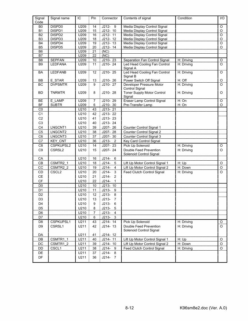
K96sm8e2.doc (Ver. A.0) 8-12
Signal Code
Signal name IC Pin Connector Contents of signal Condition I/O
B0 DISPD0 U209 14 J212- 9 Media Display Control Signal O B1 DISPD1 U209 15 J212- 10 Media Display Control Signal O B2 DISPD2 U209 16 J212- 11 Media Display Control Signal O B3 DISPD3 U209 18 J212- 12 Media Display Control Signal O B4 DISPD4 U209 19 J212- 13 Media Display Control Signal O B5 DISPD5 U209 20 J212- 14 Media Display Control Signal O B6 U209 21 (NC) B7 U209 22 (NC) B8 SEPFAN U209 10 J210- 23 Separation Fan Control Signal H: Driving O B9 LEDFANA U209 11 J210- 24 Led Head Cooling Fan Control
Signal A H: Driving O
BA LEDFANB U209 12 J210- 25 Led Head Cooling Fan Control Signal B
H: Driving O
BB E_STAR U209 13 J210- 26 Power Switch Off Signal H: Off O BC DVPSMTR U209 9 J210- 27 Developer Pressure Motor
Control Signal H: Driving O
BD TNRMTR U209 8 J210- 28 Toner Supply Motor Control Signal
H: Driving O
BE E_LAMP U209 7 J210- 29 Eraser Lamp Control Signal H: On O BF SUBTR U209 6 J210- 30 Pre-Transfer Lamp H: On O C0 U210 43 J213- 21 C1 U210 42 J213- 22 C2 U210 41 J213- 23 C3 U210 40 J213- 24 C4 LNGCNT1 U210 39 J207- 26 Counter Control Signal 1 C5 LNGCNT2 U210 38 J207- 28 Counter Control Signal 2 C6 LNGCNT3 U210 37 J207- 30 Counter Control Signal 3 C7 KEY_CNT U210 36 J213- 2 Key Card Control Signal C8 CSPKUPSL2 U210 14 J207- 23 Pick Up Solenoid H: Driving O C9 CSRSL2 U210 15 J207- 24 Double Feed Prevention
Solenoid Control Signal H: Driving O
CA U210 16 J214- 6 CB CSMTR2_1 U210 18 J214- 5 Lift Up Motor Control Signal 1 H: Up O CC CSMTR2_2 U210 19 J214- 4 Lift Up Motor Control Signal 2 H: Down O CD CSCL2 U210 20 J214- 3 Feed Clutch Control Signal H: Driving O CE U210 21 J214- 2 CF U210 22 J214- 1 D0 U210 10 J213- 10 D1 U210 11 J213- 9 D2 U210 12 J213- 8 D3 U210 13 J213- 7 D4 U210 9 J213- 6 D5 U210 8 J213- 5 D6 U210 7 J213- 4 D7 U210 6 J213- 3 D8 CSPKUPSL1 U211 43 J214- 14 Pick Up Solenoid H: Driving O D9 CSRSL1 U211 42 J214- 13 Double Feed Prevention
Solenoid Control Signal H: Driving O
DA U211 41 J214- 12 DB CSMTR1_1 U211 40 J214- 11 Lift Up Motor Control Signal 1 H: Up O DC CSMTR1_2 U211 39 J214- 10 Lift Up Motor Control Signal 2 H: Down O DD CSCL1 U211 38 J214- 9 Feed Clutch Control Signal H: Driving O DE U211 37 J214- 8 DF U211 36 J214- 7
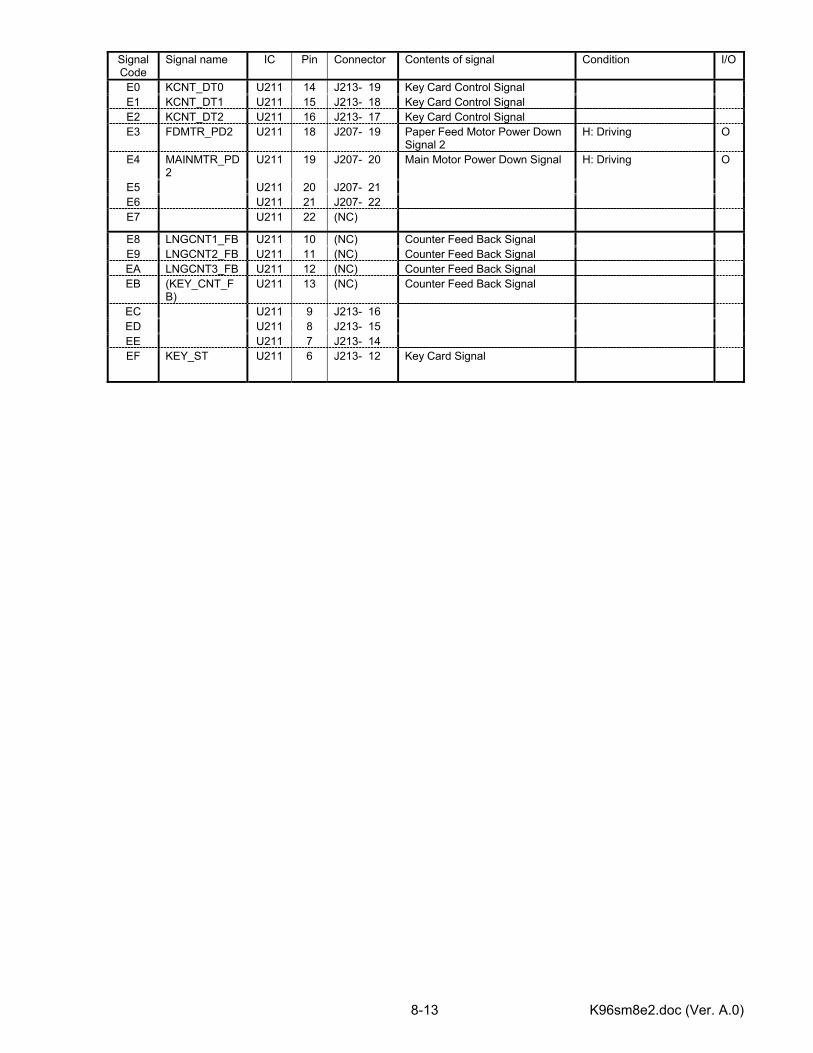
K96sm8e2.doc (Ver. A.0) 8-13
Signal Code
Signal name IC Pin Connector Contents of signal Condition I/O
E0 KCNT_DT0 U211 14 J213- 19 Key Card Control Signal E1 KCNT_DT1 U211 15 J213- 18 Key Card Control Signal E2 KCNT_DT2 U211 16 J213- 17 Key Card Control Signal E3 FDMTR_PD2 U211 18 J207- 19 Paper Feed Motor Power Down
Signal 2 H: Driving O
E4 MAINMTR_PD2
U211 19 J207- 20 Main Motor Power Down Signal H: Driving O
E5 U211 20 J207- 21 E6 U211 21 J207- 22 E7 U211 22 (NC)
E8 LNGCNT1_FB U211 10 (NC) Counter Feed Back Signal E9 LNGCNT2_FB U211 11 (NC) Counter Feed Back Signal EA LNGCNT3_FB U211 12 (NC) Counter Feed Back Signal EB (KEY_CNT_F
B) U211 13 (NC) Counter Feed Back Signal
EC U211 9 J213- 16 ED U211 8 J213- 15 EE U211 7 J213- 14 EF KEY_ST U211 6 J213- 12 Key Card Signal
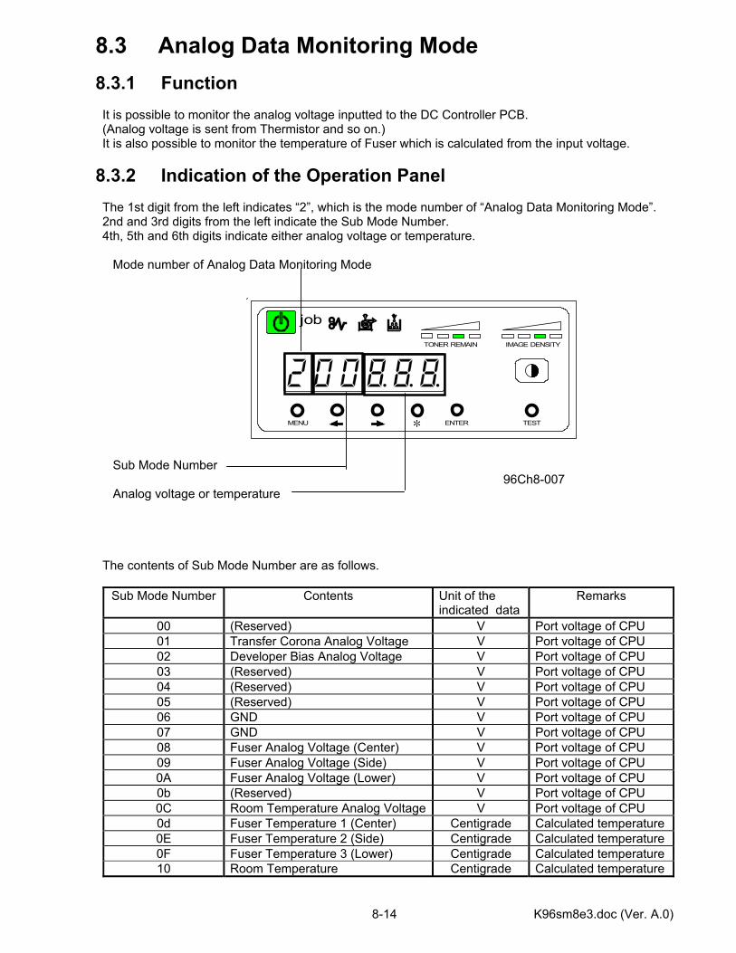
K96sm8e3.doc (Ver. A.0) 8-14
MENU ENTER TEST
TONER REMAIN IMAGE DENSITY
job
*
8.3 Analog Data Monitoring Mode 8.3.1 Function It is possible to monitor the analog voltage inputted to the DC Controller PCB. (Analog voltage is sent from Thermistor and so on.) It is also possible to monitor the temperature of Fuser which is calculated from the input voltage. 8.3.2 Indication of the Operation Panel The 1st digit from the left indicates “2”, which is the mode number of “Analog Data Monitoring Mode”. 2nd and 3rd digits from the left indicate the Sub Mode Number. 4th, 5th and 6th digits indicate either analog voltage or temperature. Mode number of Analog Data Monitoring Mode Sub Mode Number
96Ch8-007 Analog voltage or temperature The contents of Sub Mode Number are as follows.
Sub Mode Number Contents Unit of the indicated data
Remarks
00 (Reserved) V Port voltage of CPU 01 Transfer Corona Analog Voltage V Port voltage of CPU 02 Developer Bias Analog Voltage V Port voltage of CPU 03 (Reserved) V Port voltage of CPU 04 (Reserved) V Port voltage of CPU 05 (Reserved) V Port voltage of CPU 06 GND V Port voltage of CPU 07 GND V Port voltage of CPU 08 Fuser Analog Voltage (Center) V Port voltage of CPU 09 Fuser Analog Voltage (Side) V Port voltage of CPU 0A Fuser Analog Voltage (Lower) V Port voltage of CPU 0b (Reserved) V Port voltage of CPU 0C Room Temperature Analog Voltage V Port voltage of CPU 0d Fuser Temperature 1 (Center) Centigrade Calculated temperature 0E Fuser Temperature 2 (Side) Centigrade Calculated temperature 0F Fuser Temperature 3 (Lower) Centigrade Calculated temperature 10 Room Temperature Centigrade Calculated temperature
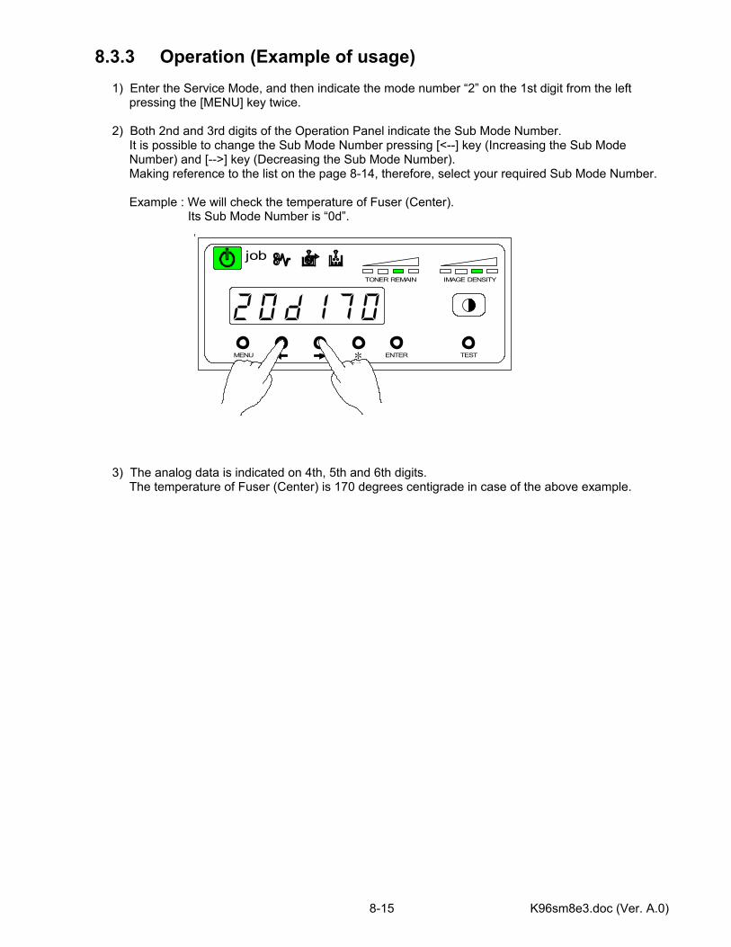
K96sm8e3.doc (Ver. A.0) 8-15
8.3.3 Operation (Example of usage) 1) Enter the Service Mode, and then indicate the mode number “2” on the 1st digit from the left pressing the [MENU] key twice. 2) Both 2nd and 3rd digits of the Operation Panel indicate the Sub Mode Number. It is possible to change the Sub Mode Number pressing [<--] key (Increasing the Sub Mode Number) and [-->] key (Decreasing the Sub Mode Number). Making reference to the list on the page 8-14, therefore, select your required Sub Mode Number. Example : We will check the temperature of Fuser (Center). Its Sub Mode Number is “0d”. 3) The analog data is indicated on 4th, 5th and 6th digits. The temperature of Fuser (Center) is 170 degrees centigrade in case of the above example.
MENU ENTER TEST
TONER REMAIN IMAGE DENSITY
job
*
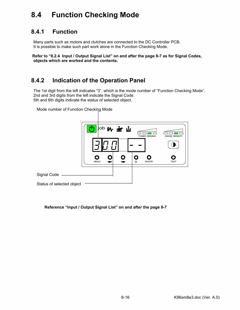
K96sm8e3.doc (Ver. A.0) 8-16
MENU ENTER TEST
TONER REMAIN IMAGE DENSITY
job
*
8.4 Function Checking Mode 8.4.1 Function Many parts such as motors and clutches are connected to the DC Controller PCB. It is possible to make such part work alone in the Function Checking Mode. Refer to “8.2.4 Input / Output Signal List” on and after the page 8-7 as for Signal Codes, objects which are worked and the contents. 8.4.2 Indication of the Operation Panel The 1st digit from the left indicates “3”, which is the mode number of “Function Checking Mode”. 2nd and 3rd digits from the left indicate the Signal Code. 5th and 6th digits indicate the status of selected object. Mode number of Function Checking Mode
Signal Code
Status of selected object
Reference “Input / Output Signal List” on and after the page 8-7
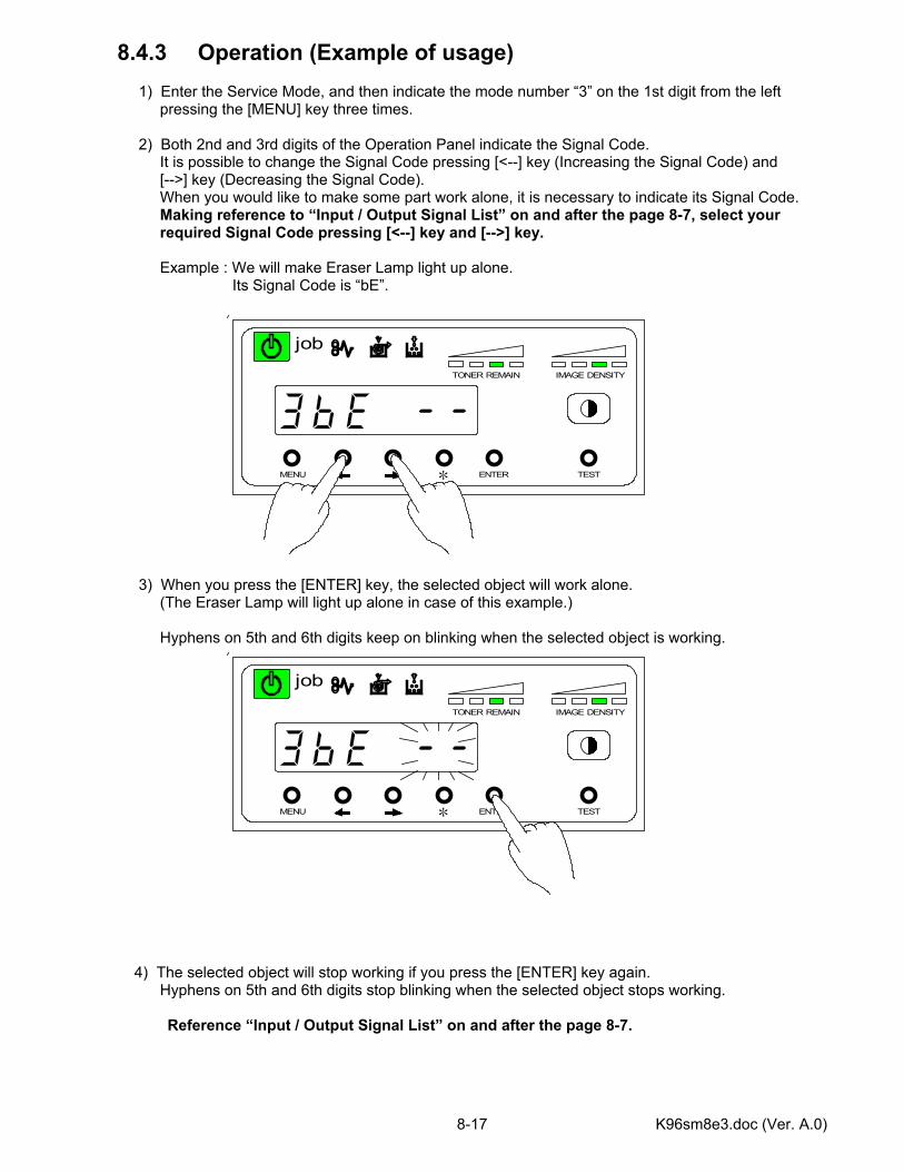
K96sm8e3.doc (Ver. A.0) 8-17
MENU ENTER TEST
TONER REMAIN IMAGE DENSITY
job
*
MENU ENTER TEST
TONER REMAIN IMAGE DENSITY
job
*
8.4.3 Operation (Example of usage) 1) Enter the Service Mode, and then indicate the mode number “3” on the 1st digit from the left pressing the [MENU] key three times. 2) Both 2nd and 3rd digits of the Operation Panel indicate the Signal Code. It is possible to change the Signal Code pressing [<--] key (Increasing the Signal Code) and [-->] key (Decreasing the Signal Code). When you would like to make some part work alone, it is necessary to indicate its Signal Code. Making reference to “Input / Output Signal List” on and after the page 8-7, select your required Signal Code pressing [<--] key and [-->] key. Example : We will make Eraser Lamp light up alone. Its Signal Code is “bE”. 3) When you press the [ENTER] key, the selected object will work alone. (The Eraser Lamp will light up alone in case of this example.) Hyphens on 5th and 6th digits keep on blinking when the selected object is working. 4) The selected object will stop working if you press the [ENTER] key again. Hyphens on 5th and 6th digits stop blinking when the selected object stops working.
Reference “Input / Output Signal List” on and after the page 8-7.
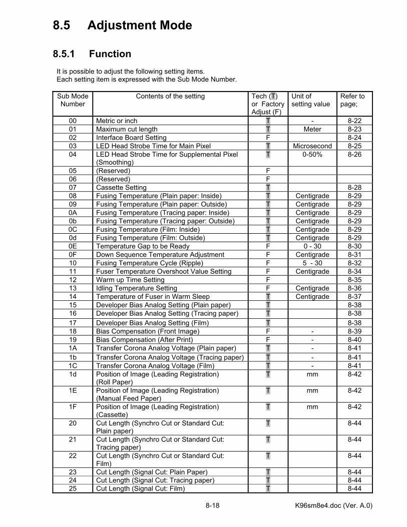
K96sm8e4.doc (Ver. A.0) 8-18
8.5 Adjustment Mode 8.5.1 Function It is possible to adjust the following setting items. Each setting item is expressed with the Sub Mode Number.
Sub Mode Number
Contents of the setting Tech (T) or Factory Adjust (F)
Unit of setting value
Refer to page;
00 Metric or inch T - 8-22 01 Maximum cut length T Meter 8-23 02 Interface Board Setting F 8-24 03 LED Head Strobe Time for Main Pixel T Microsecond 8-25 04 LED Head Strobe Time for Supplemental Pixel
(Smoothing) T 0-50% 8-26
05 (Reserved) F 06 (Reserved) F 07 Cassette Setting T 8-28 08 Fusing Temperature (Plain paper: Inside) T Centigrade 8-29 09 Fusing Temperature (Plain paper: Outside) T Centigrade 8-29 0A Fusing Temperature (Tracing paper: Inside) T Centigrade 8-29 0b Fusing Temperature (Tracing paper: Outside) T Centigrade 8-29 0C Fusing Temperature (Film: Inside) T Centigrade 8-29 0d Fusing Temperature (Film: Outside) T Centigrade 8-29 0E Temperature Gap to be Ready F 0 - 30 8-30 0F Down Sequence Temperature Adjustment F Centigrade 8-31 10 Fusing Temperature Cycle (Ripple) F 5 - 30 8-32 11 Fuser Temperature Overshoot Value Setting F Centigrade 8-34 12 Warm up Time Setting F 8-35 13 Idling Temperature Setting F Centigrade 8-36 14 Temperature of Fuser in Warm Sleep T Centigrade 8-37 15 Developer Bias Analog Setting (Plain paper) T 8-38 16 Developer Bias Analog Setting (Tracing paper) T 8-38 17 Developer Bias Analog Setting (Film) T 8-38 18 Bias Compensation (Front Image) F - 8-39 19 Bias Compensation (After Print) F - 8-40 1A Transfer Corona Analog Voltage (Plain paper) T - 8-41 1b Transfer Corona Analog Voltage (Tracing paper) T - 8-41 1C Transfer Corona Analog Voltage (Film) T - 8-41 1d Position of Image (Leading Registration)
(Roll Paper) T mm 8-42
1E Position of Image (Leading Registration) (Manual Feed Paper)
T mm 8-42
1F Position of Image (Leading Registration) (Cassette)
T mm 8-42
20 Cut Length (Synchro Cut or Standard Cut: Plain paper)
T 8-44
21 Cut Length (Synchro Cut or Standard Cut: Tracing paper)
T 8-44
22 Cut Length (Synchro Cut or Standard Cut: Film)
T 8-44
23 Cut Length (Signal Cut: Plain Paper) T 8-44 24 Cut Length (Signal Cut: Tracing paper) T 8-44 25 Cut Length (Signal Cut: Film) T 8-44
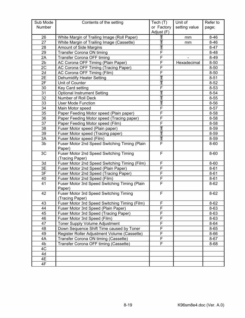
K96sm8e4.doc (Ver. A.0) 8-19
Sub Mode Number
Contents of the setting Tech (T) or Factory Adjust (F)
Unit of setting value
Refer to page;
26 White Margin of Trailing Image (Roll Paper) T mm 8-46 27 White Margin of Trailing Image (Cassette) T mm 8-46 28 Amount of Side Margins T 8-47 29 Transfer Corona ON timing F 8-48 2A Transfer Corona OFF timing F - 8-49 2b AC Corona OFF Timing (Plain Paper) F Hexadecimal 8-50 2C AC Corona OFF Timing (Tracing Paper) F 8-50 2d AC Corona OFF Timing (Film) F 8-50 2E Dehumidify Heater Setting T 8-51 2F Unit of Counter T 8-52 30 Key Card setting F 8-53 31 Optional Instrument Setting T 8-54 32 Number of Roll Deck T 8-55 33 User Mode Function T 8-56 34 Main Motor speed F 8-57 35 Paper Feeding Motor speed (Plain paper) F 8-58 36 Paper Feeding Motor speed (Tracing paper) F 8-58 37 Paper Feeding Motor speed (Film) F 8-58 38 Fuser Motor speed (Plain paper) T 8-59 39 Fuser Motor speed (Tracing paper) T 8-59 3A Fuser Motor speed (Film) T 8-59 3b Fuser Motor 2nd Speed Switching Timing (Plain
Paper) F 8-60
3C Fuser Motor 2nd Speed Switching Timing (Tracing Paper)
F 8-60
3d Fuser Motor 2nd Speed Switching Timing (Film) F 8-60 3E Fuser Motor 2nd Speed (Plain Paper) F 8-61 3F Fuser Motor 2nd Speed (Tracing Paper) F 8-61 40 Fuser Motor 2nd Speed (Film) F 8-61 41 Fuser Motor 3rd Speed Switching Timing (Plain
Paper) F 8-62
42 Fuser Motor 3rd Speed Switching Timing (Tracing Paper)
F 8-62
43 Fuser Motor 3rd Speed Switching Timing (Film) F 8-62 44 Fuser Motor 3rd Speed (Plain Paper) F 8-63 45 Fuser Motor 3rd Speed (Tracing Paper) F 8-63 46 Fuser Motor 3rd Speed (Film) F 8-63 47 Toner Supply Volume Adjustment F 8-64 48 Down Sequence Shift Time caused by Toner F 8-65 49 Register Roller Adjustment Volume (Cassette) F 8-66 4A Transfer Corona ON timing (Cassette) F 8-67 4b Transfer Corona OFF timing (Cassette) F 8-68 4C 4d 4E 4F
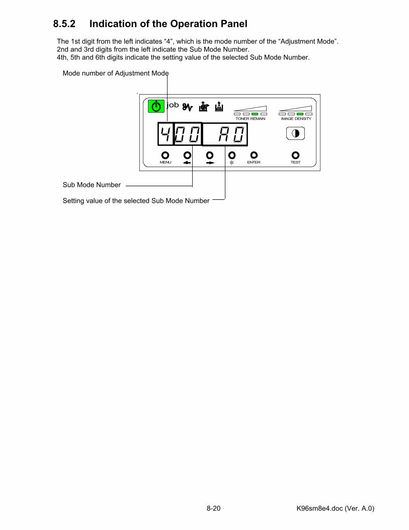
K96sm8e4.doc (Ver. A.0) 8-20
8.5.2 Indication of the Operation Panel The 1st digit from the left indicates “4”, which is the mode number of the “Adjustment Mode”. 2nd and 3rd digits from the left indicate the Sub Mode Number. 4th, 5th and 6th digits indicate the setting value of the selected Sub Mode Number. Mode number of Adjustment Mode Sub Mode Number
Setting value of the selected Sub Mode Number
MENU ENTER TEST
TONER REMAIN IMAGE DENSITY
job
*
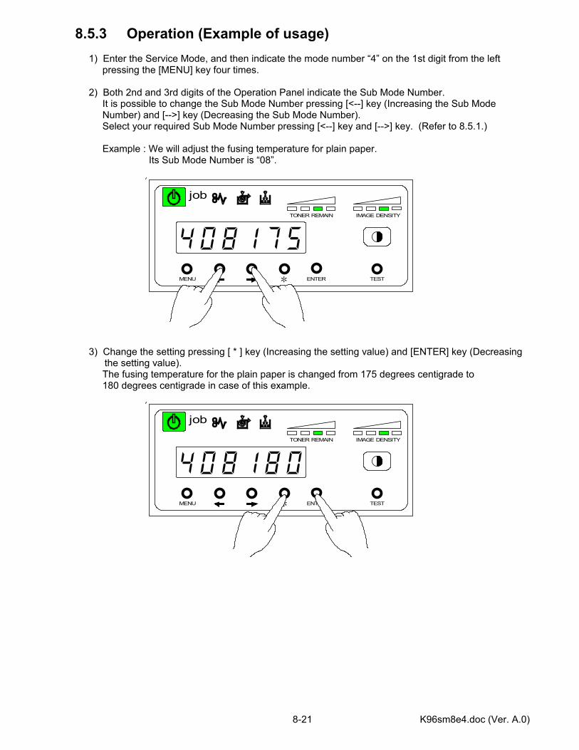
K96sm8e4.doc (Ver. A.0) 8-21
MENU ENTER TEST
TONER REMAIN IMAGE DENSITY
job
*
8.5.3 Operation (Example of usage) 1) Enter the Service Mode, and then indicate the mode number “4” on the 1st digit from the left pressing the [MENU] key four times. 2) Both 2nd and 3rd digits of the Operation Panel indicate the Sub Mode Number. It is possible to change the Sub Mode Number pressing [<--] key (Increasing the Sub Mode Number) and [-->] key (Decreasing the Sub Mode Number). Select your required Sub Mode Number pressing [<--] key and [-->] key. (Refer to 8.5.1.) Example : We will adjust the fusing temperature for plain paper. Its Sub Mode Number is “08”. 3) Change the setting pressing [ * ] key (Increasing the setting value) and [ENTER] key (Decreasing
the setting value). The fusing temperature for the plain paper is changed from 175 degrees centigrade to 180 degrees centigrade in case of this example.
MENU ENTER TEST
TONER REMAIN IMAGE DENSITY
job
*
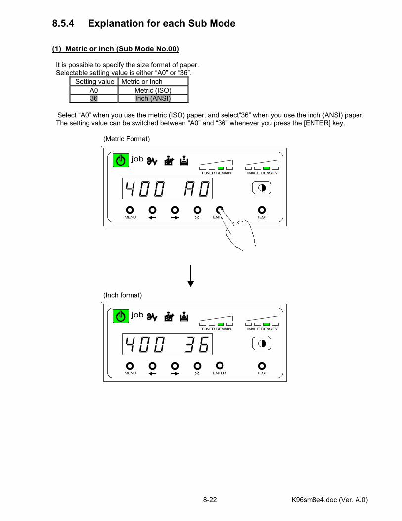
K96sm8e4.doc (Ver. A.0) 8-22
MENU ENTER TEST
TONER REMAIN IMAGE DENSITY
job
*
8.5.4 Explanation for each Sub Mode (1) Metric or inch (Sub Mode No.00) It is possible to specify the size format of paper. Selectable setting value is either “A0” or “36”.
Setting value Metric or Inch A0 Metric (ISO) 36 Inch (ANSI)
Select “A0” when you use the metric (ISO) paper, and select“36” when you use the inch (ANSI) paper.
The setting value can be switched between “A0” and “36” whenever you press the [ENTER] key. (Metric Format) (Inch format)
MENU ENTER TEST
TONER REMAIN IMAGE DENSITY
job
*
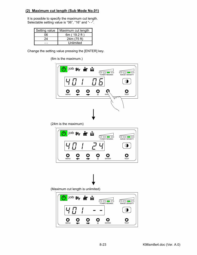
K96sm8e4.doc (Ver. A.0) 8-23
MENU ENTER TEST
TONER REMAIN IMAGE DENSITY
job
*
(2) Maximum cut length (Sub Mode No.01) It is possible to specify the maximum cut length. Selectable setting value is “06”, “16” and “- -”.
Setting value Maximum cut length 06 6m ( 19.2 ft ) 24 24m (75 ft) - - Unlimited
Change the setting value pressing the [ENTER] key. (6m is the maximum.) (24m is the maximum) (Maximum cut length is unlimited)
MENU ENTER TEST
TONER REMAIN IMAGE DENSITY
job
*
MENU ENTER TEST
TONER REMAIN IMAGE DENSITY
job
*
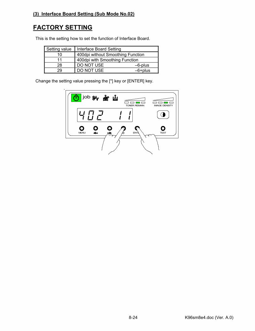
K96sm8e4.doc (Ver. A.0) 8-24
MENU ENTER TEST
TONER REMAIN IMAGE DENSITY
job
*
(3) Interface Board Setting (Sub Mode No.02) FACTORY SETTING This is the setting how to set the function of Interface Board.
Setting value Interface Board Setting 10 400dpi without Smoothing Function 11 400dpi with Smoothing Function 28 DO NOT USE –6-plus 29 DO NOT USE –6+plus
Change the setting value pressing the [*] key or [ENTER] key.
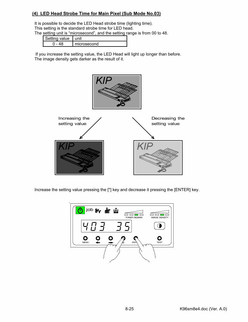
K96sm8e4.doc (Ver. A.0) 8-25
MENU ENTER TEST
TONER REMAIN IMAGE DENSITY
job
*
(4) LED Head Strobe Time for Main Pixel (Sub Mode No.03) It is possible to decide the LED Head strobe time (lighting time). This setting is the standard strobe time for LED head. The setting unit is “microsecond”, and the setting range is from 00 to 48.
Setting value unit 0 - 48 microsecond
If you increase the setting value, the LED Head will light up longer than before.
The image density gets darker as the result of it. Increase the setting value pressing the [*] key and decrease it pressing the [ENTER] key.
Increasing thesetting value
Decreasing thesetting value
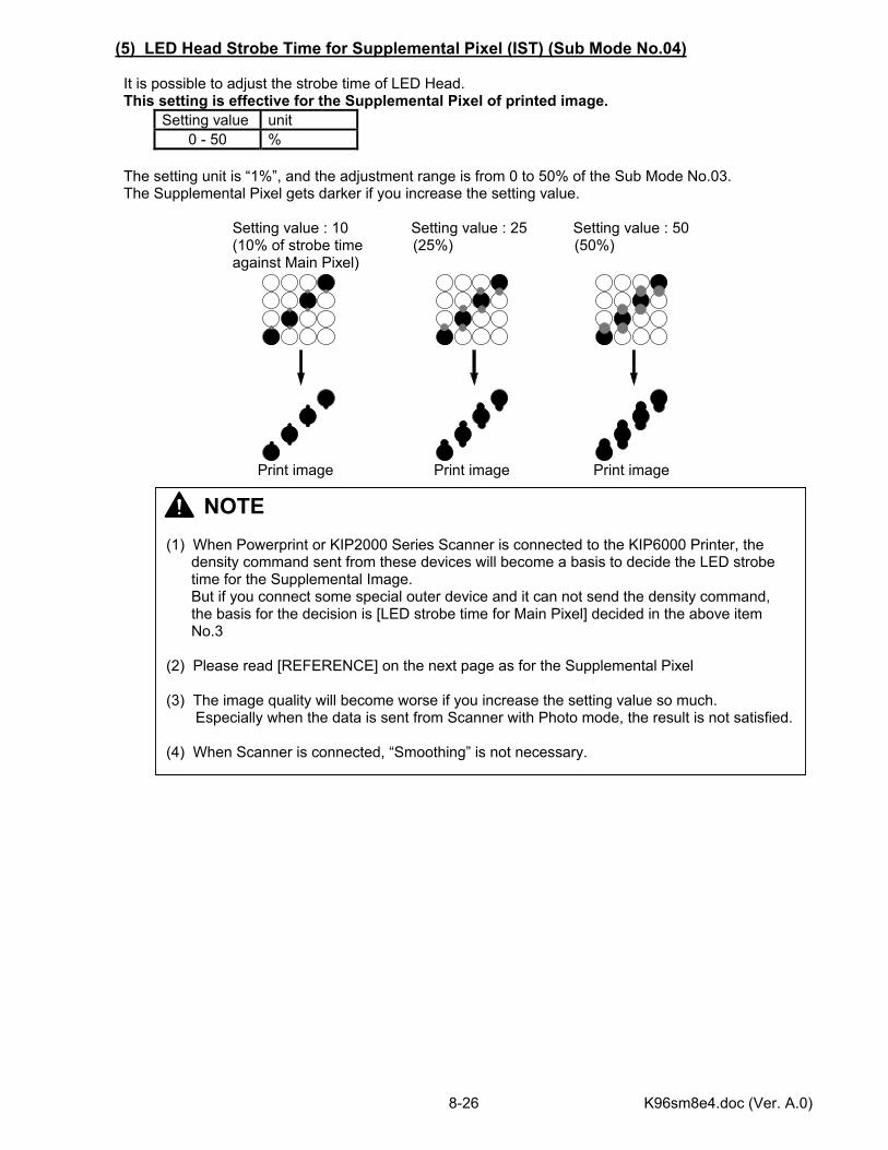
K96sm8e4.doc (Ver. A.0) 8-26
(5) LED Head Strobe Time for Supplemental Pixel (IST) (Sub Mode No.04) It is possible to adjust the strobe time of LED Head. This setting is effective for the Supplemental Pixel of printed image.
Setting value unit 0 - 50 %
The setting unit is “1%”, and the adjustment range is from 0 to 50% of the Sub Mode No.03. The Supplemental Pixel gets darker if you increase the setting value. Setting value : 10 Setting value : 25 Setting value : 50 (10% of strobe time (25%) (50%) against Main Pixel) Print image Print image Print image
NOTE (1) When Powerprint or KIP2000 Series Scanner is connected to the KIP6000 Printer, the density command sent from these devices will become a basis to decide the LED strobe time for the Supplemental Image. But if you connect some special outer device and it can not send the density command, the basis for the decision is [LED strobe time for Main Pixel] decided in the above item No.3 (2) Please read [REFERENCE] on the next page as for the Supplemental Pixel (3) The image quality will become worse if you increase the setting value so much. Especially when the data is sent from Scanner with Photo mode, the result is not satisfied. (4) When Scanner is connected, “Smoothing” is not necessary.
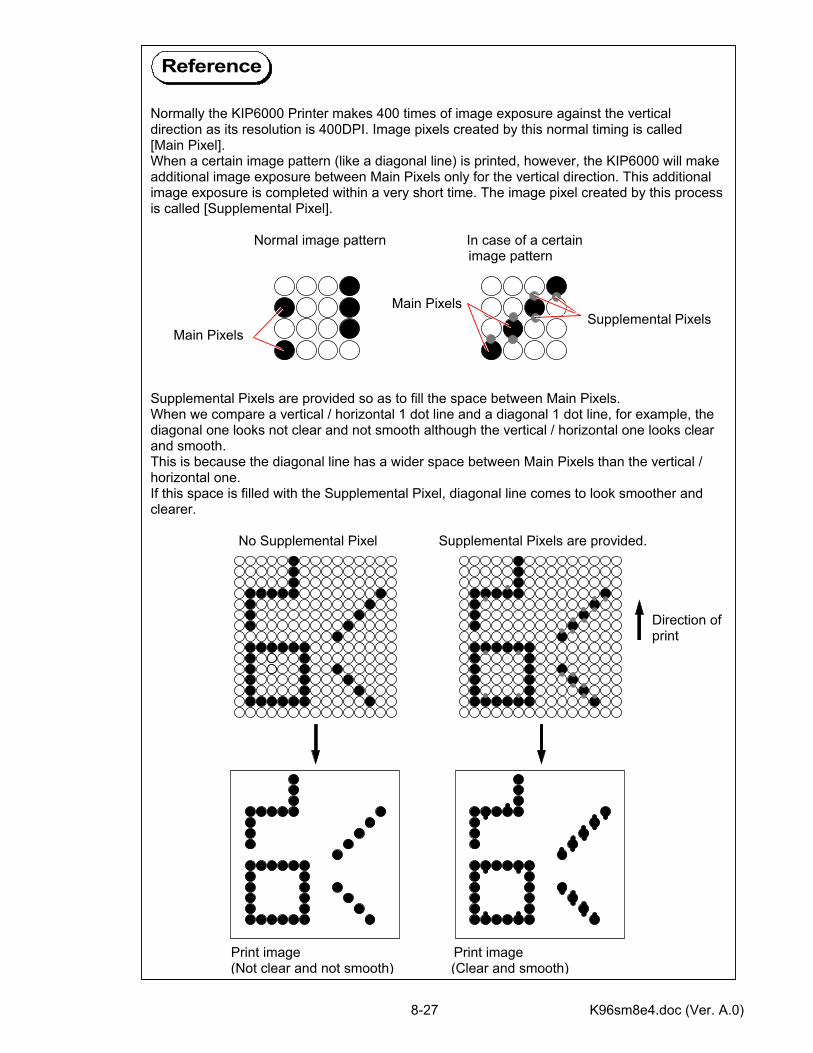
K96sm8e4.doc (Ver. A.0) 8-27
Normally the KIP6000 Printer makes 400 times of image exposure against the vertical direction as its resolution is 400DPI. Image pixels created by this normal timing is called [Main Pixel]. When a certain image pattern (like a diagonal line) is printed, however, the KIP6000 will make additional image exposure between Main Pixels only for the vertical direction. This additional image exposure is completed within a very short time. The image pixel created by this process is called [Supplemental Pixel]. Normal image pattern In case of a certain image pattern Main Pixels Supplemental Pixels Main Pixels Supplemental Pixels are provided so as to fill the space between Main Pixels. When we compare a vertical / horizontal 1 dot line and a diagonal 1 dot line, for example, the diagonal one looks not clear and not smooth although the vertical / horizontal one looks clear and smooth. This is because the diagonal line has a wider space between Main Pixels than the vertical / horizontal one. If this space is filled with the Supplemental Pixel, diagonal line comes to look smoother and clearer. No Supplemental Pixel Supplemental Pixels are provided. Direction of print Print image Print image (Not clear and not smooth) (Clear and smooth)
Reference
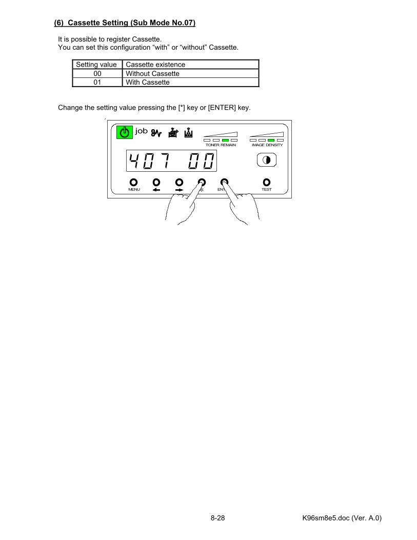
K96sm8e5.doc (Ver. A.0) 8-28
MENU ENTER TEST
TONER REMAIN IMAGE DENSITY
job
*
(6) Cassette Setting (Sub Mode No.07) It is possible to register Cassette. You can set this configuration “with” or “without” Cassette.
Setting value Cassette existence 00 Without Cassette 01 With Cassette
Change the setting value pressing the [*] key or [ENTER] key.
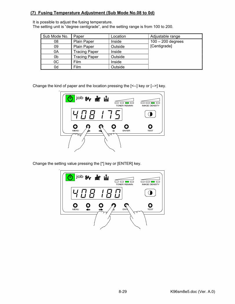
K96sm8e5.doc (Ver. A.0) 8-29
MENU ENTER TEST
TONER REMAIN IMAGE DENSITY
job
*
MENU ENTER TEST
TONER REMAIN IMAGE DENSITY
job
*
(7) Fusing Temperature Adjustment (Sub Mode No.08 to 0d) It is possible to adjust the fusing temperature. The setting unit is “degree centigrade”, and the setting range is from 100 to 200.
Sub Mode No. Paper Location Adjustable range 08 Plain Paper Inside 09 Plain Paper Outside 0A Tracing Paper Inside 0b Tracing Paper Outside 0C Film Inside 0d Film Outside
100 – 200 degrees [Centigrade]
Change the kind of paper and the location pressing the [<--] key or [-->] key. Change the setting value pressing the [*] key or [ENTER] key.
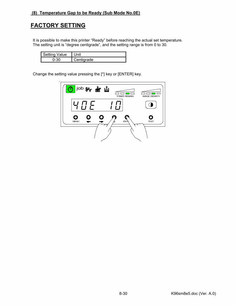
K96sm8e5.doc (Ver. A.0) 8-30
MENU ENTER TEST
TONER REMAIN IMAGE DENSITY
job
*
(8) Temperature Gap to be Ready (Sub Mode No.0E) FACTORY SETTING It is possible to make this printer “Ready” before reaching the actual set temperature. The setting unit is “degree centigrade”, and the setting range is from 0 to 30.
Setting Value Unit 0-30 Centigrade
Change the setting value pressing the [*] key or [ENTER] key.
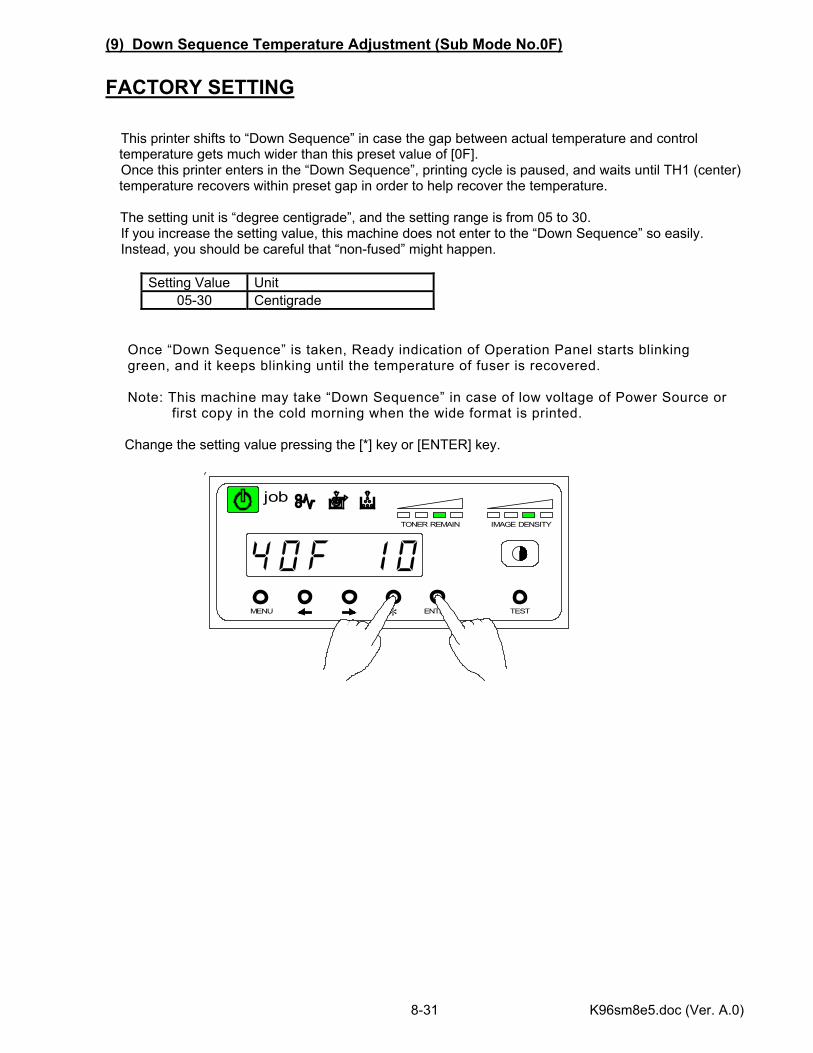
K96sm8e5.doc (Ver. A.0) 8-31
MENU ENTER TEST
TONER REMAIN IMAGE DENSITY
job
*
(9) Down Sequence Temperature Adjustment (Sub Mode No.0F) FACTORY SETTING This printer shifts to “Down Sequence” in case the gap between actual temperature and control
temperature gets much wider than this preset value of [0F]. Once this printer enters in the “Down Sequence”, printing cycle is paused, and waits until TH1 (center)
temperature recovers within preset gap in order to help recover the temperature. The setting unit is “degree centigrade”, and the setting range is from 05 to 30.
If you increase the setting value, this machine does not enter to the “Down Sequence” so easily. Instead, you should be careful that “non-fused” might happen.
Setting Value Unit 05-30 Centigrade
Once “Down Sequence” is taken, Ready indication of Operation Panel starts blinking green, and it keeps blinking until the temperature of fuser is recovered. Note: This machine may take “Down Sequence” in case of low voltage of Power Source or first copy in the cold morning when the wide format is printed. Change the setting value pressing the [*] key or [ENTER] key.
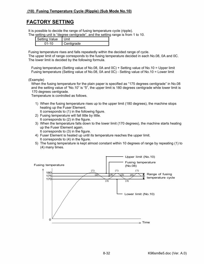
K96sm8e5.doc (Ver. A.0) 8-32
(10) Fusing Temperature Cycle (Ripple) (Sub Mode No.10) FACTORY SETTING It is possible to decide the range of fusing temperature cycle (ripple). The setting unit is “degree centigrade”, and the setting range is from 1 to 10.
Setting Value Unit 01-10 Centigrade
Fusing temperature rises and falls repeatedly within the decided range of cycle. The upper limit of range corresponds to the fusing temperature decided in each No.08, 0A and 0C. The lower limit is decided by the following formula. Fusing temperature (Setting value of No.08, 0A and 0C) + Setting value of No.10 = Upper limit Fusing temperature (Setting value of No.08, 0A and 0C) - Setting value of No.10 = Lower limit (Example) When the fusing temperature for the plain paper is specified as “175 degrees centigrade” in No.08 and the setting value of “No.10” is “5”, the upper limit is 180 degrees centigrade while lower limit is
170 degrees centigrade. Temperature is controlled as follows. 1) When the fusing temperature rises up to the upper limit (180 degrees), the machine stops heating up the Fuser Element. It corresponds to (1) in the following figure. 2) Fusing temperature will fall little by little. It corresponds to (2) in the figure. 3) When the temperature falls down to the lower limit (170 degrees), the machine starts heating up the Fuser Element again. It corresponds to (3) in the figure. 4) Fuser Element is heated up until its temperature reaches the upper limit. It corresponds to (4) in the figure. 5) The fusing temperature is kept almost constant within 10 degrees of range by repeating (1) to
(4) many times.
Fusing temperature
Time0
(1)
(2)
(3)
Fusing temperature(No.08)
Lower limit (No.10)
180175 Range of fusing
temperature cycle
(1)
(3)
(4) (2) (4)
(1)
170
Upper limit (No.10)

K96sm8e5.doc (Ver. A.0) 8-33
MENU ENTER TEST
TONER REMAIN IMAGE DENSITY
job
*
Change the setting value pressing the [*] key or [ENTER] key.
Note If the range of temperature cycle is too small because you select a smaller setting value in the No.10, the Fuser Element will be heated up many times in a short period. It will cause to shorten the life of such part as SSR.
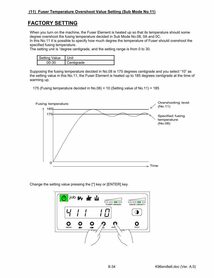
K96sm8e6.doc (Ver. A.0) 8-34
MENU ENTER TEST
TONER REMAIN IMAGE DENSITY
job
*
(11) Fuser Temperature Overshoot Value Setting (Sub Mode No.11) FACTORY SETTING When you turn on the machine, the Fuser Element is heated up so that its temperature should some degree overshoot the fusing temperature decided in Sub Mode No.08, 0A and 0C. In this No.11 it is possible to specify how much degree the temperature of Fuser should overshoot the specified fusing temperature. The setting unit is “degree centigrade, and the setting range is from 0 to 30.
Setting Value Unit 00-30 Centigrade
Supposing the fusing temperature decided in No.08 is 175 degrees centigrade and you select “10” as the setting value in this No.11, the Fuser Element is heated up to 185 degrees centigrade at the time of warming up. 175 (Fusing temperature decided in No.08) + 10 (Setting value of No.11) = 185 Change the setting value pressing the [*] key or [ENTER] key.
Fusing temperature
Time0
175
185
Specified fusingtemperature(No.08)
Overshooting level(No.11)
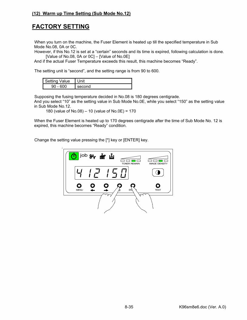
K96sm8e6.doc (Ver. A.0) 8-35
MENU ENTER TEST
TONER REMAIN IMAGE DENSITY
job
*
(12) Warm up Time Setting (Sub Mode No.12) FACTORY SETTING When you turn on the machine, the Fuser Element is heated up till the specified temperature in Sub Mode No.08, 0A or 0C.
However, if this No.12 is set at a “certain” seconds and its time is expired, following calculation is done. [Value of No.08, 0A or 0C] – [Value of No.0E] And if the actual Fuser Temperature exceeds this result, this machine becomes “Ready”.
The setting unit is “second”, and the setting range is from 90 to 600.
Setting Value Unit 90 - 600 second
Supposing the fusing temperature decided in No.08 is 180 degrees centigrade. And you select “10” as the setting value in Sub Mode No.0E, while you select “150” as the setting value in Sub Mode No.12. 180 (value of No.08) – 10 (value of No.0E) = 170 When the Fuser Element is heated up to 170 degrees centigrade after the time of Sub Mode No. 12 is expired, this machine becomes “Ready” condition.
Change the setting value pressing the [*] key or [ENTER] key.
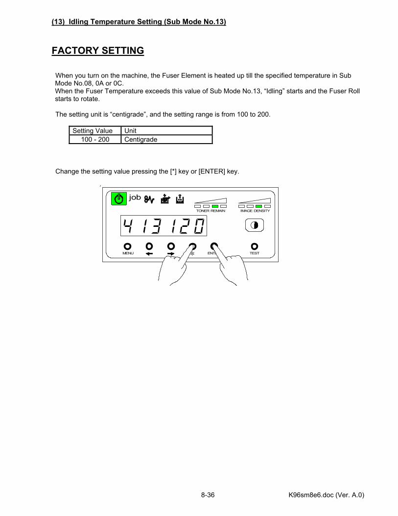
K96sm8e6.doc (Ver. A.0) 8-36
MENU ENTER TEST
TONER REMAIN IMAGE DENSITY
job
*
(13) Idling Temperature Setting (Sub Mode No.13) FACTORY SETTING When you turn on the machine, the Fuser Element is heated up till the specified temperature in Sub Mode No.08, 0A or 0C. When the Fuser Temperature exceeds this value of Sub Mode No.13, “Idling” starts and the Fuser Roll starts to rotate.
The setting unit is “centigrade”, and the setting range is from 100 to 200.
Setting Value Unit 100 - 200 Centigrade
Change the setting value pressing the [*] key or [ENTER] key.
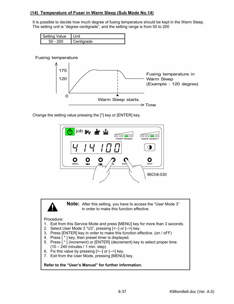
K96sm8e6.doc (Ver. A.0) 8-37
MENU ENTER TEST
TONER REMAIN IMAGE DENSITY
job
*
(14) Temperature of Fuser in Warm Sleep (Sub Mode No.14) It is possible to decide how much degree of fusing temperature should be kept in the Warm Sleep. The setting unit is “degree centigrade”, and the setting range is from 50 to 200
Setting Value Unit 50 - 200 Centigrade
Change the setting value pressing the [*] key or [ENTER] key. 96Ch8-030
Fusing temperature
Time
0Warm Sleep starts.
175
120Fusing temperature inWarm Sleep(Example : 120 degree)
Note: After this setting, you have to access the “User Mode 3” in order to make this function effective.
Procedure: 1. Exit from this Service Mode and press [MENU] key for more than 3 seconds. 2. Select User Mode 3 “U3”, pressing [<--] or [-->] key. 3. Press [ENTER] key in order to make this function effective. (on / oFF) 4. Press [ * ] key, then preset timer is displayed. 5. Press [ * ] (increment) or [ENTER] (decrement) key to select proper time.
(10 – 240 minutes / 1 min. step) 6. Fix this value by pressing [<--] or [-->] key. 7. Exit from the User Mode, pressing [MENU] key. Refer to the “User’s Manual” for further information.
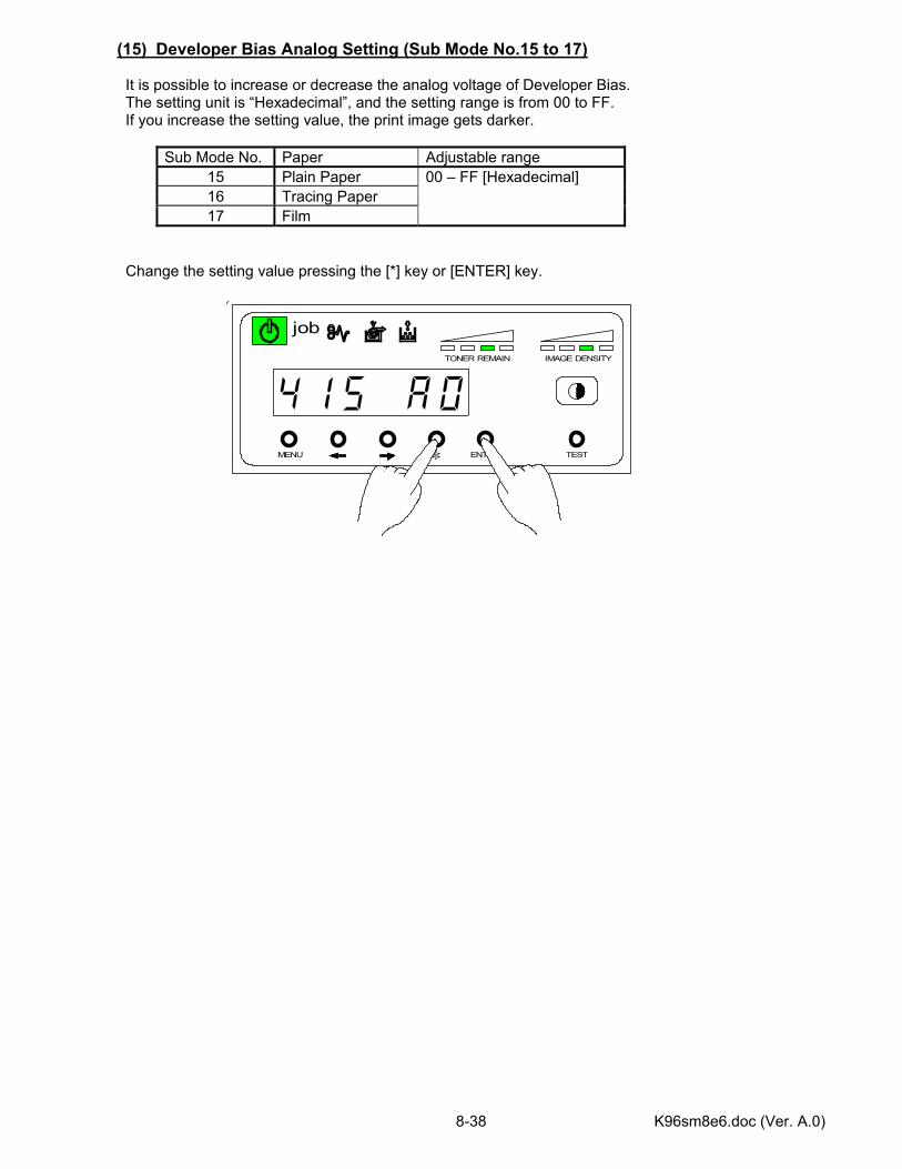
K96sm8e6.doc (Ver. A.0) 8-38
MENU ENTER TEST
TONER REMAIN IMAGE DENSITY
job
*
(15) Developer Bias Analog Setting (Sub Mode No.15 to 17) It is possible to increase or decrease the analog voltage of Developer Bias. The setting unit is “Hexadecimal”, and the setting range is from 00 to FF. If you increase the setting value, the print image gets darker.
Sub Mode No. Paper Adjustable range 15 Plain Paper 16 Tracing Paper 17 Film
00 – FF [Hexadecimal]
Change the setting value pressing the [*] key or [ENTER] key.
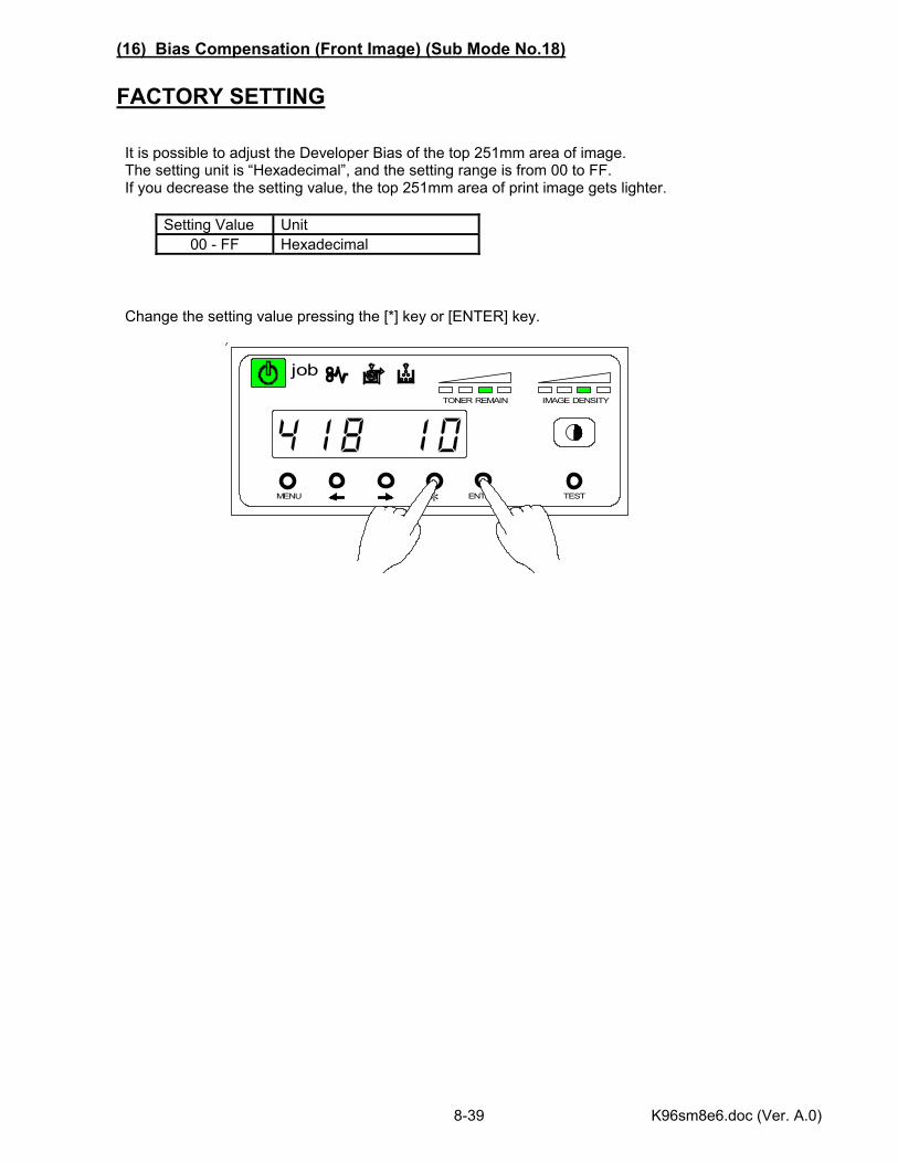
K96sm8e6.doc (Ver. A.0) 8-39
MENU ENTER TEST
TONER REMAIN IMAGE DENSITY
job
*
(16) Bias Compensation (Front Image) (Sub Mode No.18) FACTORY SETTING It is possible to adjust the Developer Bias of the top 251mm area of image. The setting unit is “Hexadecimal”, and the setting range is from 00 to FF. If you decrease the setting value, the top 251mm area of print image gets lighter.
Setting Value Unit 00 - FF Hexadecimal
Change the setting value pressing the [*] key or [ENTER] key.
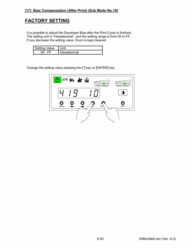
K96sm8e6.doc (Ver. A.0) 8-40
MENU ENTER TEST
TONER REMAIN IMAGE DENSITY
job
*
(17) Bias Compensation (After Print) (Sub Mode No.19) FACTORY SETTING It is possible to adjust the Developer Bias after the Print Cycle is finished. The setting unit is “Hexadecimal”, and the setting range is from 00 to FF. If you decrease the setting value, Drum is kept cleaned.
Setting Value Unit 00 - FF Hexadecimal
Change the setting value pressing the [*] key or [ENTER] key.
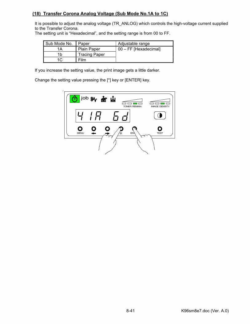
K96sm8e7.doc (Ver. A.0) 8-41
MENU ENTER TEST
TONER REMAIN IMAGE DENSITY
job
*
(18) Transfer Corona Analog Voltage (Sub Mode No.1A to 1C) It is possible to adjust the analog voltage (TR_ANLOG) which controls the high-voltage current supplied to the Transfer Corona. The setting unit is “Hexadecimal”, and the setting range is from 00 to FF.
Sub Mode No. Paper Adjustable range 1A Plain Paper 1b Tracing Paper 1C Film
00 – FF [Hexadecimal]
If you increase the setting value, the print image gets a little darker. Change the setting value pressing the [*] key or [ENTER] key.
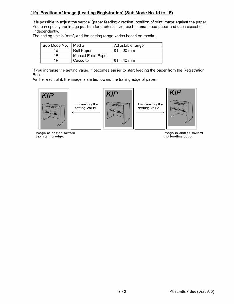
K96sm8e7.doc (Ver. A.0) 8-42
(19) Position of Image (Leading Registration) (Sub Mode No.1d to 1F) It is possible to adjust the vertical (paper feeding direction) position of print image against the paper. You can specify the image position for each roll size, each manual feed paper and each cassette independently.
The setting unit is “mm”, and the setting range varies based on media.
Sub Mode No. Media Adjustable range 1d Roll Paper 1E Manual Feed Paper
01 – 20 mm
1F Cassette 01 – 40 mm If you increase the setting value, it becomes earlier to start feeding the paper from the Registration Roller. As the result of it, the image is shifted toward the trailing edge of paper.
Decreasing thesetting value
Increasing thesetting value
Image is shifted towardthe trailing edge.
Image is shifted towardthe leading edge.
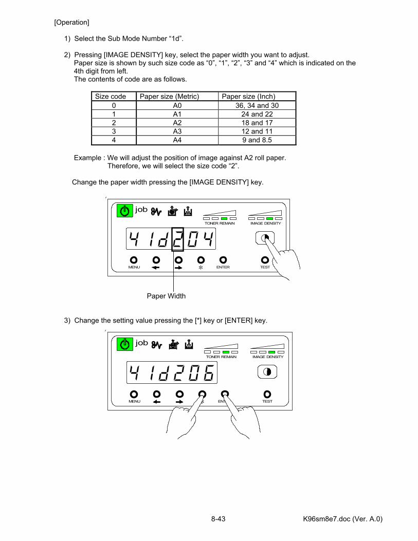
K96sm8e7.doc (Ver. A.0) 8-43
MENU ENTER TEST
TONER REMAIN IMAGE DENSITY
job
*
MENU ENTER TEST
TONER REMAIN IMAGE DENSITY
job
*
[Operation] 1) Select the Sub Mode Number “1d”. 2) Pressing [IMAGE DENSITY] key, select the paper width you want to adjust. Paper size is shown by such size code as “0”, “1”, “2”, “3” and “4” which is indicated on the 4th digit from left. The contents of code are as follows.
Size code Paper size (Metric) Paper size (Inch) 0 A0 36, 34 and 30 1 A1 24 and 22 2 A2 18 and 17 3 A3 12 and 11 4 A4 9 and 8.5
Example : We will adjust the position of image against A2 roll paper. Therefore, we will select the size code “2”. Change the paper width pressing the [IMAGE DENSITY] key. Paper Width 3) Change the setting value pressing the [*] key or [ENTER] key.
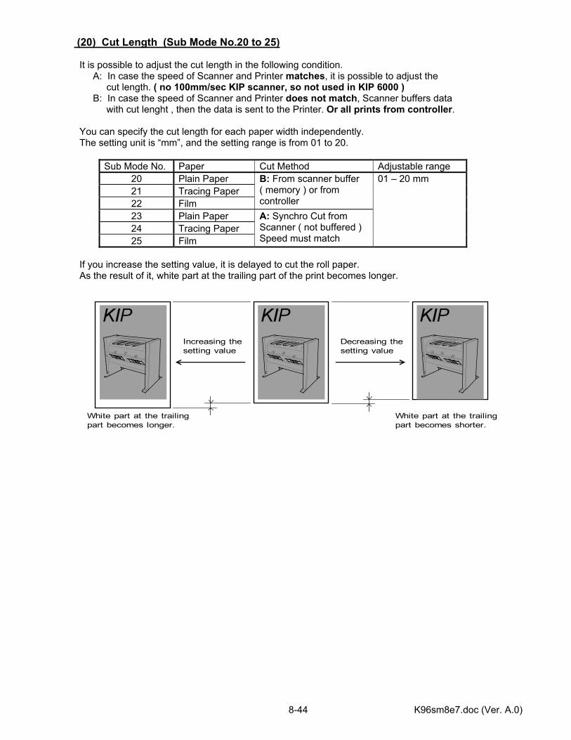
K96sm8e7.doc (Ver. A.0) 8-44
(20) Cut Length (Sub Mode No.20 to 25) It is possible to adjust the cut length in the following condition. A: In case the speed of Scanner and Printer matches, it is possible to adjust the cut length. ( no 100mm/sec KIP scanner, so not used in KIP 6000 ) B: In case the speed of Scanner and Printer does not match, Scanner buffers data with cut lenght , then the data is sent to the Printer. Or all prints from controller. You can specify the cut length for each paper width independently. The setting unit is “mm”, and the setting range is from 01 to 20.
Sub Mode No. Paper Cut Method Adjustable range 20 Plain Paper 21 Tracing Paper 22 Film
B: From scanner buffer ( memory ) or from controller
23 Plain Paper 24 Tracing Paper 25 Film
A: Synchro Cut from Scanner ( not buffered ) Speed must match
01 – 20 mm
If you increase the setting value, it is delayed to cut the roll paper. As the result of it, white part at the trailing part of the print becomes longer.
Decreasing thesetting value
Increasing thesetting value
White part at the trailingpart becomes longer.
White part at the trailingpart becomes shorter.
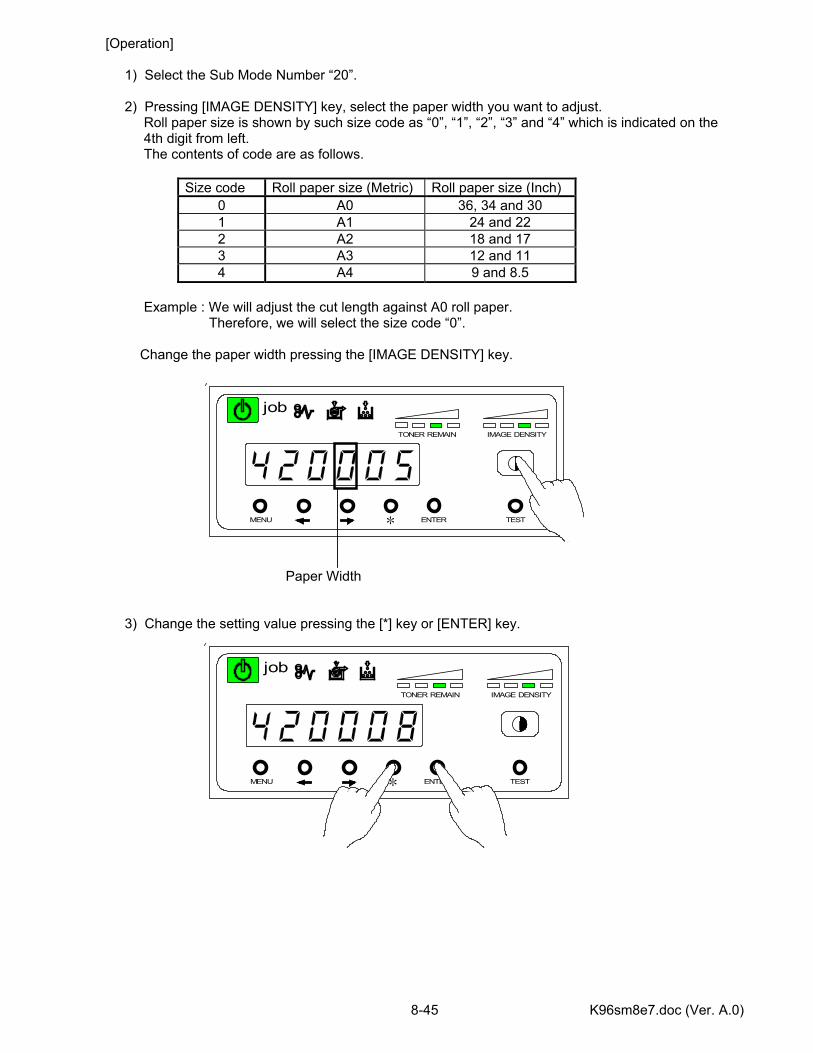
K96sm8e7.doc (Ver. A.0) 8-45
MENU ENTER TEST
TONER REMAIN IMAGE DENSITY
job
*
MENU ENTER TEST
TONER REMAIN IMAGE DENSITY
job
*
[Operation] 1) Select the Sub Mode Number “20”. 2) Pressing [IMAGE DENSITY] key, select the paper width you want to adjust. Roll paper size is shown by such size code as “0”, “1”, “2”, “3” and “4” which is indicated on the 4th digit from left. The contents of code are as follows.
Size code Roll paper size (Metric) Roll paper size (Inch) 0 A0 36, 34 and 30 1 A1 24 and 22 2 A2 18 and 17 3 A3 12 and 11 4 A4 9 and 8.5
Example : We will adjust the cut length against A0 roll paper. Therefore, we will select the size code “0”. Change the paper width pressing the [IMAGE DENSITY] key. Paper Width 3) Change the setting value pressing the [*] key or [ENTER] key.
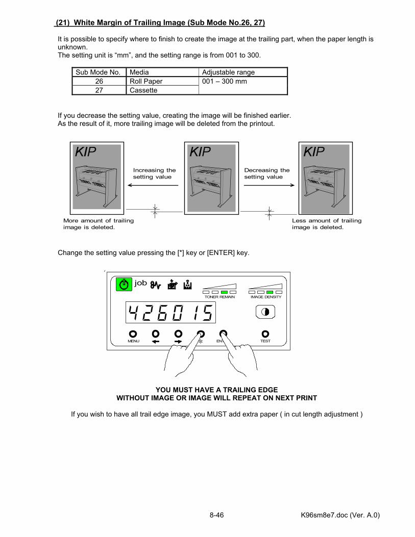
K96sm8e7.doc (Ver. A.0) 8-46
MENU ENTER TEST
TONER REMAIN IMAGE DENSITY
job
*
(21) White Margin of Trailing Image (Sub Mode No.26, 27) It is possible to specify where to finish to create the image at the trailing part, when the paper length is unknown. The setting unit is “mm”, and the setting range is from 001 to 300.
Sub Mode No. Media Adjustable range 26 Roll Paper 27 Cassette
001 – 300 mm
If you decrease the setting value, creating the image will be finished earlier. As the result of it, more trailing image will be deleted from the printout. Change the setting value pressing the [*] key or [ENTER] key.
YOU MUST HAVE A TRAILING EDGE WITHOUT IMAGE OR IMAGE WILL REPEAT ON NEXT PRINT
If you wish to have all trail edge image, you MUST add extra paper ( in cut length adjustment )
Increasing thesetting value
More amount of trailingimage is deleted.
Less amount of trailingimage is deleted.
Decreasing thesetting value
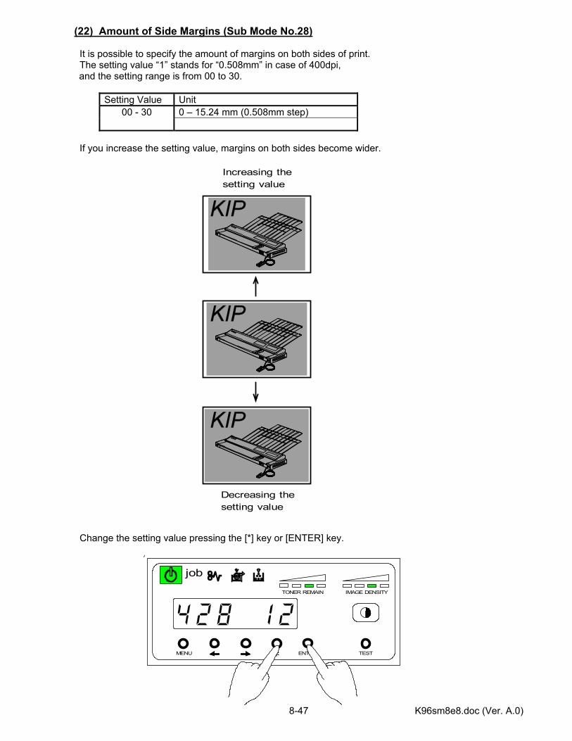
K96sm8e8.doc (Ver. A.0) 8-47
MENU ENTER TEST
TONER REMAIN IMAGE DENSITY
job
*
(22) Amount of Side Margins (Sub Mode No.28) It is possible to specify the amount of margins on both sides of print. The setting value “1” stands for “0.508mm” in case of 400dpi, and the setting range is from 00 to 30.
Setting Value Unit
0 – 15.24 mm (0.508mm step) 00 - 30
If you increase the setting value, margins on both sides become wider. Change the setting value pressing the [*] key or [ENTER] key.
Increasing thesetting value
Decreasing thesetting value

K96sm8e8.doc (Ver. A.0) 8-48
MENU ENTER TEST
TONER REMAIN IMAGE DENSITY
job
*
(23) Transfer Corona ON Timing (Sub Mode No.29)
FACTORY ADJUSTMENT It is possible to adjust the timing to make the Transfer Corona start discharging. The setting unit is “mm”, and the setting range is from 001 to 100.
Setting Value Unit 001 - 100 mm
If you increase the setting value, the timing that the Transfer Corona starts discharging is delayed. It means more amount of leading image (toner image) is not transferred to the paper but remains on the Drum. As the result of it, the printout has a longer white margin on its leading part. (Increasing the setting value by “1”, white part on the print gets 1mm longer.) Change the setting value pressing the [*] key or [ENTER] key.
Increasing thesetting value
Transfer Charger starts chargingat this point.
This part of toner image is not transferedfrom the Drum to the paper.
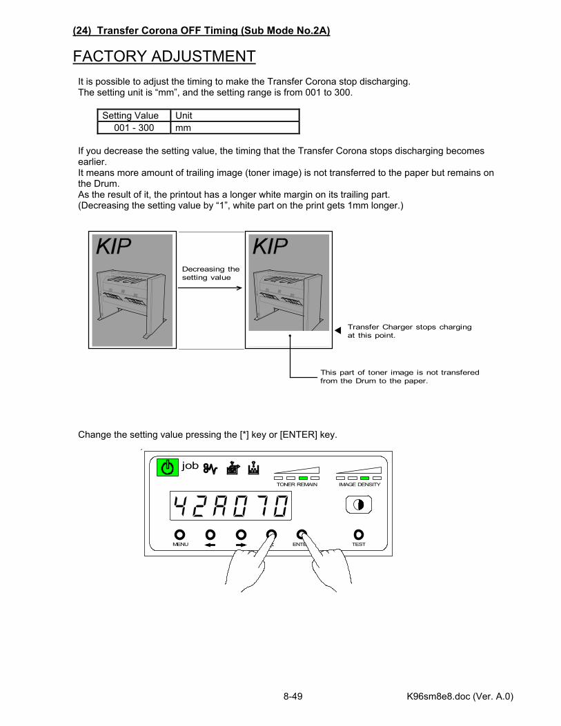
K96sm8e8.doc (Ver. A.0) 8-49
MENU ENTER TEST
TONER REMAIN IMAGE DENSITY
job
*
(24) Transfer Corona OFF Timing (Sub Mode No.2A)
FACTORY ADJUSTMENT It is possible to adjust the timing to make the Transfer Corona stop discharging. The setting unit is “mm”, and the setting range is from 001 to 300.
Setting Value Unit 001 - 300 mm
If you decrease the setting value, the timing that the Transfer Corona stops discharging becomes earlier. It means more amount of trailing image (toner image) is not transferred to the paper but remains on the Drum. As the result of it, the printout has a longer white margin on its trailing part. (Decreasing the setting value by “1”, white part on the print gets 1mm longer.) Change the setting value pressing the [*] key or [ENTER] key.
Decreasing thesetting value
Transfer Charger stops chargingat this point.
This part of toner image is not transferedfrom the Drum to the paper.
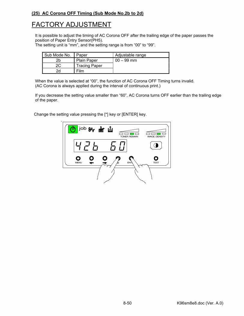
K96sm8e8.doc (Ver. A.0) 8-50
MENU ENTER TEST
TONER REMAIN IMAGE DENSITY
job
*
(25) AC Corona OFF Timing (Sub Mode No.2b to 2d)
FACTORY ADJUSTMENT It is possible to adjust the timing of AC Corona OFF after the trailing edge of the paper passes the position of Paper Entry Sensor(PH5). The setting unit is “mm”, and the setting range is from “00” to “99”.
Sub Mode No. Paper Adjustable range 2b Plain Paper 2C Tracing Paper 2d Film
00 – 99 mm
When the value is selected at “00”, the function of AC Corona OFF Timing turns invalid. (AC Corona is always applied during the interval of continuous print.) If you decrease the setting value smaller than “60”, AC Corona turns OFF earlier than the trailing edge of the paper. Change the setting value pressing the [*] key or [ENTER] key.
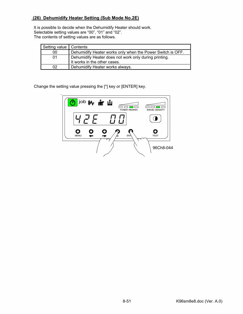
K96sm8e8.doc (Ver. A.0) 8-51
MENU ENTER TEST
TONER REMAIN IMAGE DENSITY
job
*
(26) Dehumidify Heater Setting (Sub Mode No.2E) It is possible to decide when the Dehumidify Heater should work. Selectable setting values are “00”, “01” and “02”. The contents of setting values are as follows.
Setting value Contents 00 Dehumidify Heater works only when the Power Switch is OFF. 01 Dehumidify Heater does not work only during printing.
It works in the other cases. 02 Dehumidify Heater works always.
Change the setting value pressing the [*] key or [ENTER] key. 96Ch8-044
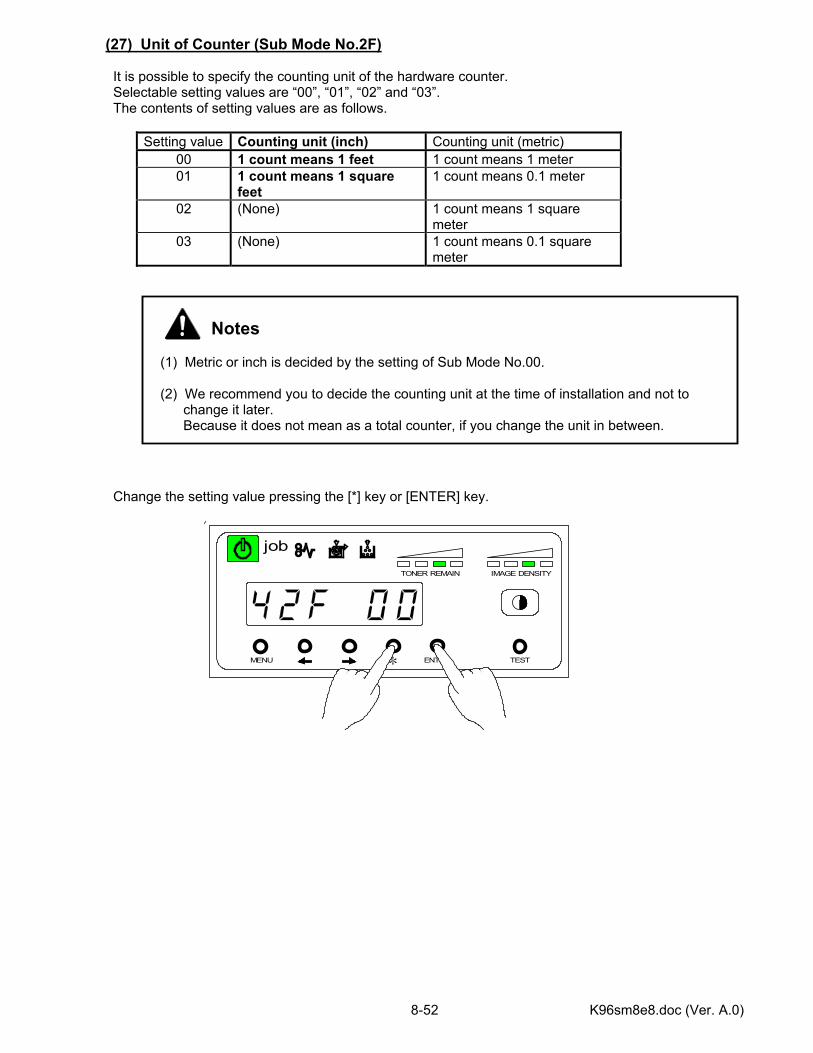
K96sm8e8.doc (Ver. A.0) 8-52
MENU ENTER TEST
TONER REMAIN IMAGE DENSITY
job
*
(27) Unit of Counter (Sub Mode No.2F) It is possible to specify the counting unit of the hardware counter. Selectable setting values are “00”, “01”, “02” and “03”. The contents of setting values are as follows.
Setting value Counting unit (inch) Counting unit (metric) 00 1 count means 1 feet 1 count means 1 meter 01 1 count means 1 square
feet 1 count means 0.1 meter
02 (None) 1 count means 1 square meter
03 (None) 1 count means 0.1 square meter
Change the setting value pressing the [*] key or [ENTER] key.
Notes (1) Metric or inch is decided by the setting of Sub Mode No.00. (2) We recommend you to decide the counting unit at the time of installation and not to change it later. Because it does not mean as a total counter, if you change the unit in between.
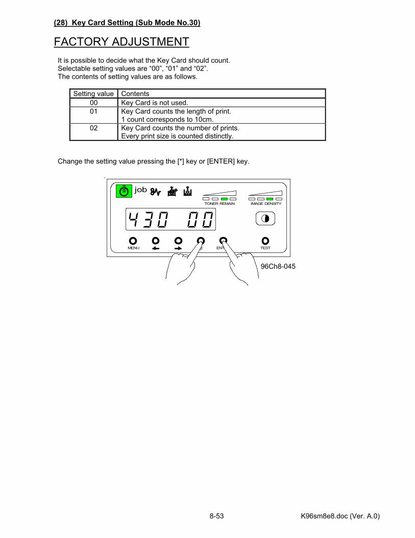
K96sm8e8.doc (Ver. A.0) 8-53
MENU ENTER TEST
TONER REMAIN IMAGE DENSITY
job
*
(28) Key Card Setting (Sub Mode No.30)
FACTORY ADJUSTMENT It is possible to decide what the Key Card should count. Selectable setting values are “00”, “01” and “02”. The contents of setting values are as follows.
Setting value Contents 00 Key Card is not used. 01 Key Card counts the length of print.
1 count corresponds to 10cm. 02 Key Card counts the number of prints.
Every print size is counted distinctly. Change the setting value pressing the [*] key or [ENTER] key. 96Ch8-045
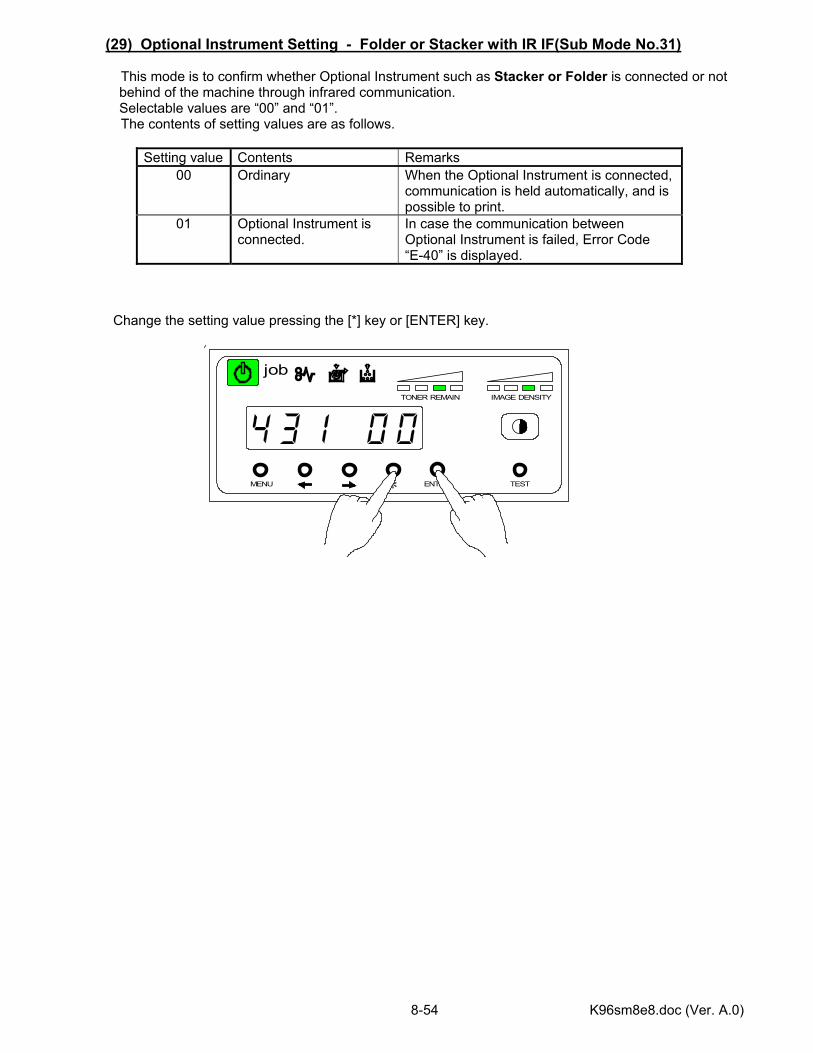
K96sm8e8.doc (Ver. A.0) 8-54
MENU ENTER TEST
TONER REMAIN IMAGE DENSITY
job
*
(29) Optional Instrument Setting - Folder or Stacker with IR IF(Sub Mode No.31) This mode is to confirm whether Optional Instrument such as Stacker or Folder is connected or not
behind of the machine through infrared communication. Selectable values are “00” and “01”.
The contents of setting values are as follows.
Setting value Contents Remarks 00 Ordinary When the Optional Instrument is connected,
communication is held automatically, and is possible to print.
01 Optional Instrument is connected.
In case the communication between Optional Instrument is failed, Error Code “E-40” is displayed.
Change the setting value pressing the [*] key or [ENTER] key.
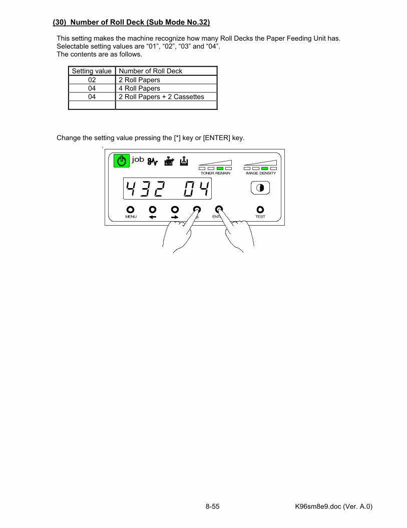
K96sm8e9.doc (Ver. A.0) 8-55
MENU ENTER TEST
TONER REMAIN IMAGE DENSITY
job
*
(30) Number of Roll Deck (Sub Mode No.32) This setting makes the machine recognize how many Roll Decks the Paper Feeding Unit has. Selectable setting values are “01”, “02”, “03” and “04”. The contents are as follows.
Setting value Number of Roll Deck 02 2 Roll Papers 04 4 Roll Papers 04 2 Roll Papers + 2 Cassettes
Change the setting value pressing the [*] key or [ENTER] key.
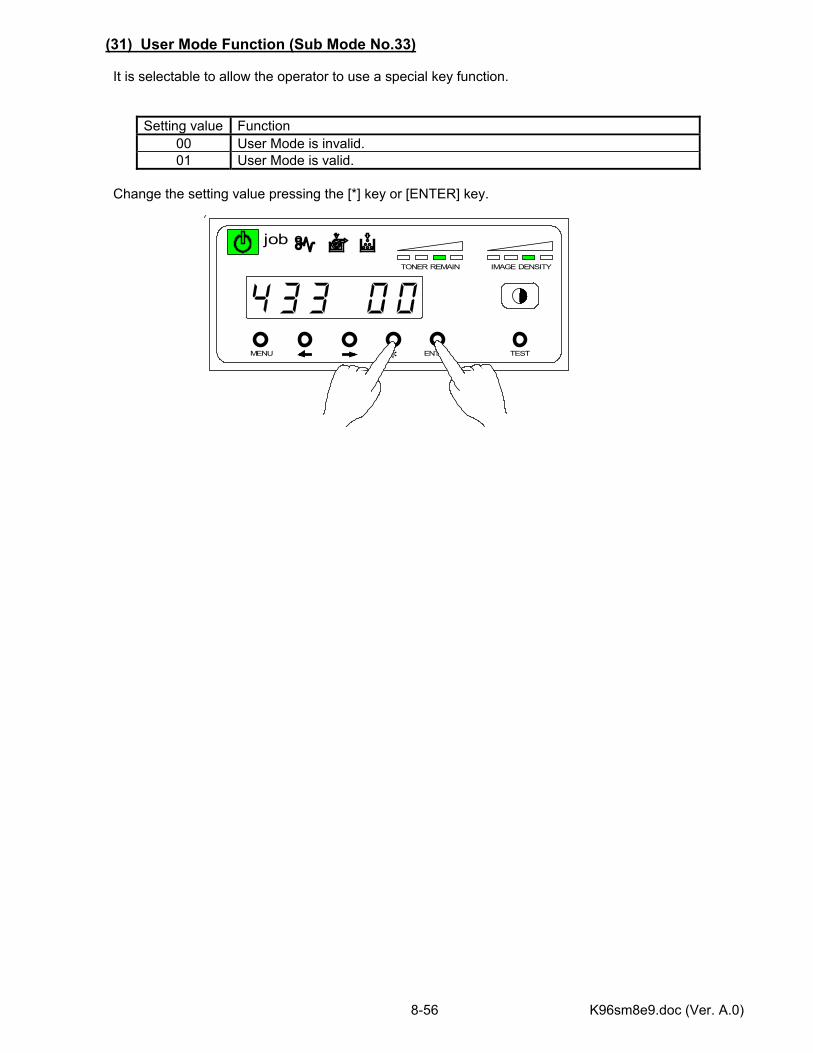
K96sm8e9.doc (Ver. A.0) 8-56
MENU ENTER TEST
TONER REMAIN IMAGE DENSITY
job
*
(31) User Mode Function (Sub Mode No.33) It is selectable to allow the operator to use a special key function.
Setting value Function 00 User Mode is invalid. 01 User Mode is valid.
Change the setting value pressing the [*] key or [ENTER] key.
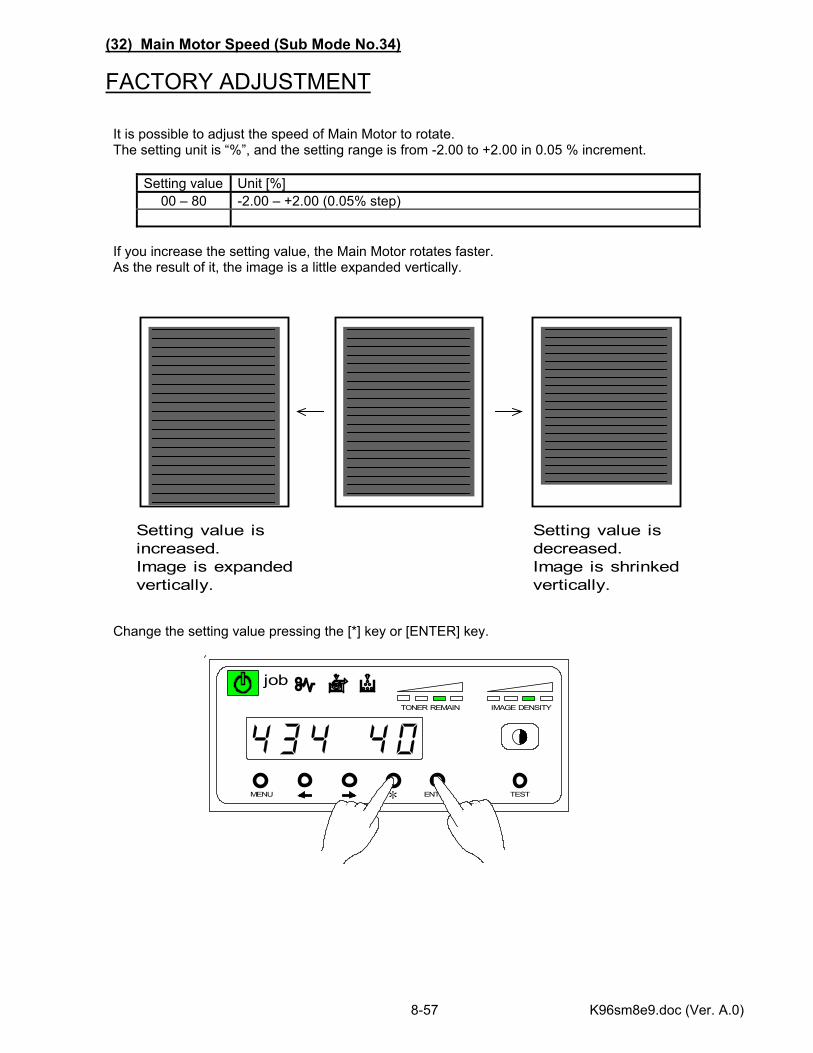
K96sm8e9.doc (Ver. A.0) 8-57
MENU ENTER TEST
TONER REMAIN IMAGE DENSITY
job
*
(32) Main Motor Speed (Sub Mode No.34)
FACTORY ADJUSTMENT It is possible to adjust the speed of Main Motor to rotate. The setting unit is “%”, and the setting range is from -2.00 to +2.00 in 0.05 % increment.
Setting value Unit [%] 00 – 80 -2.00 – +2.00 (0.05% step)
If you increase the setting value, the Main Motor rotates faster. As the result of it, the image is a little expanded vertically. Change the setting value pressing the [*] key or [ENTER] key.
Setting value isincreased.Image is expandedvertically.
Setting value isdecreased.Image is shrinkedvertically.
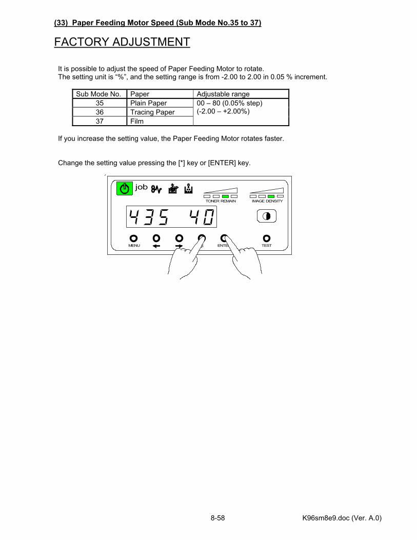
K96sm8e9.doc (Ver. A.0) 8-58
MENU ENTER TEST
TONER REMAIN IMAGE DENSITY
job
*
(33) Paper Feeding Motor Speed (Sub Mode No.35 to 37)
FACTORY ADJUSTMENT It is possible to adjust the speed of Paper Feeding Motor to rotate. The setting unit is “%”, and the setting range is from -2.00 to 2.00 in 0.05 % increment.
Sub Mode No. Paper Adjustable range 35 Plain Paper 36 Tracing Paper 37 Film
00 – 80 (0.05% step) (-2.00 – +2.00%)
If you increase the setting value, the Paper Feeding Motor rotates faster. Change the setting value pressing the [*] key or [ENTER] key.
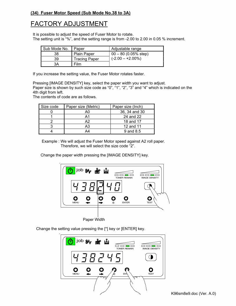
K96sm8e9.doc (Ver. A.0) 8-59
MENU ENTER TEST
TONER REMAIN IMAGE DENSITY
job
*
MENU ENTER TEST
TONER REMAIN IMAGE DENSITY
job
*
(34) Fuser Motor Speed (Sub Mode No.38 to 3A)
FACTORY ADJUSTMENT It is possible to adjust the speed of Fuser Motor to rotate. The setting unit is “%”, and the setting range is from -2.00 to 2.00 in 0.05 % increment.
Sub Mode No. Paper Adjustable range 38 Plain Paper 39 Tracing Paper 3A Film
00 – 80 (0.05% step) (-2.00 – +2.00%)
If you increase the setting value, the Fuser Motor rotates faster. Pressing [IMAGE DENSITY] key, select the paper width you want to adjust. Paper size is shown by such size code as “0”, “1”, “2”, “3” and “4” which is indicated on the 4th digit from left. The contents of code are as follows.
Size code Paper size (Metric) Paper size (Inch) 0 A0 36, 34 and 30 1 A1 24 and 22 2 A2 18 and 17 3 A3 12 and 11 4 A4 9 and 8.5
Example : We will adjust the Fuser Motor speed against A2 roll paper. Therefore, we will select the size code “2”. Change the paper width pressing the [IMAGE DENSITY] key. Paper Width Change the setting value pressing the [*] key or [ENTER] key.
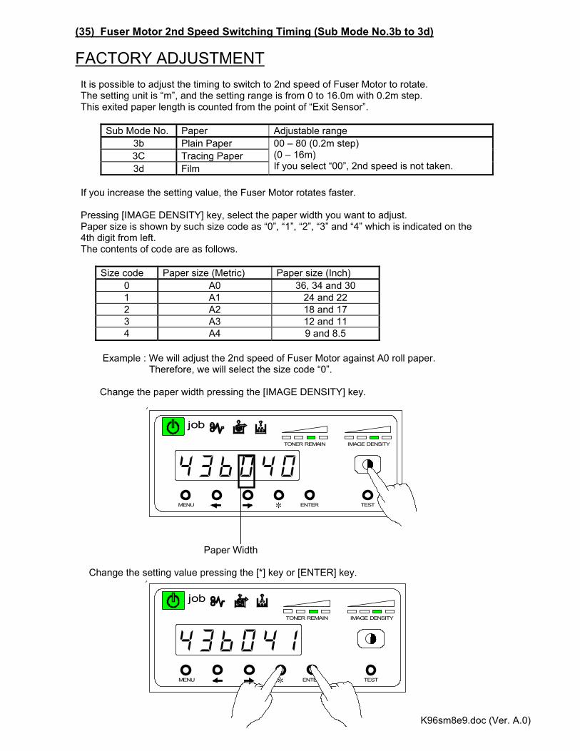
K96sm8e9.doc (Ver. A.0) 8-60
MENU ENTER TEST
TONER REMAIN IMAGE DENSITY
job
*
MENU ENTER TEST
TONER REMAIN IMAGE DENSITY
job
*
(35) Fuser Motor 2nd Speed Switching Timing (Sub Mode No.3b to 3d)
FACTORY ADJUSTMENT It is possible to adjust the timing to switch to 2nd speed of Fuser Motor to rotate. The setting unit is “m”, and the setting range is from 0 to 16.0m with 0.2m step. This exited paper length is counted from the point of “Exit Sensor”.
Sub Mode No. Paper Adjustable range 3b Plain Paper 3C Tracing Paper 3d Film
00 – 80 (0.2m step) (0 – 16m) If you select “00”, 2nd speed is not taken.
If you increase the setting value, the Fuser Motor rotates faster. Pressing [IMAGE DENSITY] key, select the paper width you want to adjust. Paper size is shown by such size code as “0”, “1”, “2”, “3” and “4” which is indicated on the 4th digit from left. The contents of code are as follows.
Size code Paper size (Metric) Paper size (Inch) 0 A0 36, 34 and 30 1 A1 24 and 22 2 A2 18 and 17 3 A3 12 and 11 4 A4 9 and 8.5
Example : We will adjust the 2nd speed of Fuser Motor against A0 roll paper. Therefore, we will select the size code “0”. Change the paper width pressing the [IMAGE DENSITY] key. Paper Width Change the setting value pressing the [*] key or [ENTER] key.
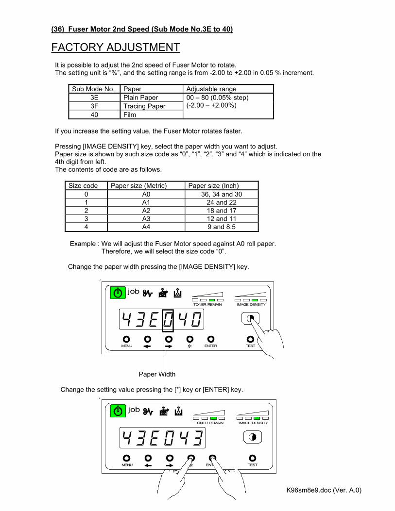
K96sm8e9.doc (Ver. A.0) 8-61
MENU ENTER TEST
TONER REMAIN IMAGE DENSITY
job
*
MENU ENTER TEST
TONER REMAIN IMAGE DENSITY
job
*
(36) Fuser Motor 2nd Speed (Sub Mode No.3E to 40)
FACTORY ADJUSTMENT It is possible to adjust the 2nd speed of Fuser Motor to rotate. The setting unit is “%”, and the setting range is from -2.00 to +2.00 in 0.05 % increment.
Sub Mode No. Paper Adjustable range 3E Plain Paper 3F Tracing Paper 40 Film
00 – 80 (0.05% step) (-2.00 – +2.00%)
If you increase the setting value, the Fuser Motor rotates faster. Pressing [IMAGE DENSITY] key, select the paper width you want to adjust. Paper size is shown by such size code as “0”, “1”, “2”, “3” and “4” which is indicated on the 4th digit from left. The contents of code are as follows.
Size code Paper size (Metric) Paper size (Inch) 0 A0 36, 34 and 30 1 A1 24 and 22 2 A2 18 and 17 3 A3 12 and 11 4 A4 9 and 8.5
Example : We will adjust the Fuser Motor speed against A0 roll paper. Therefore, we will select the size code “0”. Change the paper width pressing the [IMAGE DENSITY] key. Paper Width Change the setting value pressing the [*] key or [ENTER] key.
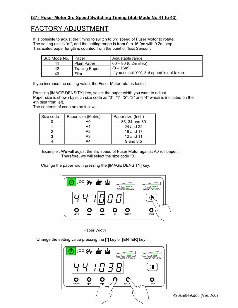
K96sm8e9.doc (Ver. A.0) 8-62
MENU ENTER TEST
TONER REMAIN IMAGE DENSITY
job
*
MENU ENTER TEST
TONER REMAIN IMAGE DENSITY
job
*
(37) Fuser Motor 3rd Speed Switching Timing (Sub Mode No.41 to 43)
FACTORY ADJUSTMENT It is possible to adjust the timing to switch to 3rd speed of Fuser Motor to rotate. The setting unit is “m”, and the setting range is from 0 to 16.0m with 0.2m step. This exited paper length is counted from the point of “Exit Sensor”.
Sub Mode No. Paper Adjustable range 41 Plain Paper 42 Tracing Paper 43 Film
00 – 80 (0.2m step) (0 – 16m) If you select “00”, 3rd speed is not taken.
If you increase the setting value, the Fuser Motor rotates faster. Pressing [IMAGE DENSITY] key, select the paper width you want to adjust. Paper size is shown by such size code as “0”, “1”, “2”, “3” and “4” which is indicated on the 4th digit from left. The contents of code are as follows.
Size code Paper size (Metric) Paper size (Inch) 0 A0 36, 34 and 30 1 A1 24 and 22 2 A2 18 and 17 3 A3 12 and 11 4 A4 9 and 8.5
Example : We will adjust the 3rd speed of Fuser Motor against A0 roll paper. Therefore, we will select the size code “0”. Change the paper width pressing the [IMAGE DENSITY] key. Paper Width Change the setting value pressing the [*] key or [ENTER] key.
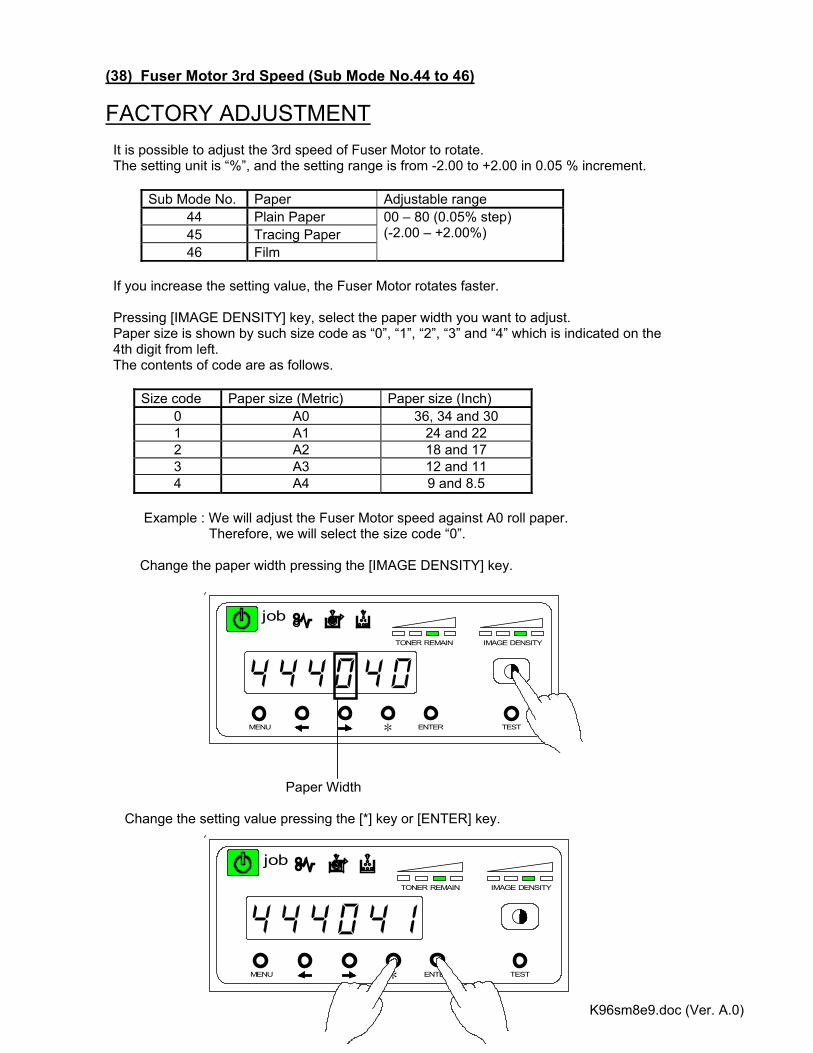
K96sm8e9.doc (Ver. A.0) 8-63
MENU ENTER TEST
TONER REMAIN IMAGE DENSITY
job
*
MENU ENTER TEST
TONER REMAIN IMAGE DENSITY
job
*
(38) Fuser Motor 3rd Speed (Sub Mode No.44 to 46)
FACTORY ADJUSTMENT It is possible to adjust the 3rd speed of Fuser Motor to rotate. The setting unit is “%”, and the setting range is from -2.00 to +2.00 in 0.05 % increment.
Sub Mode No. Paper Adjustable range 44 Plain Paper 45 Tracing Paper 46 Film
00 – 80 (0.05% step) (-2.00 – +2.00%)
If you increase the setting value, the Fuser Motor rotates faster. Pressing [IMAGE DENSITY] key, select the paper width you want to adjust. Paper size is shown by such size code as “0”, “1”, “2”, “3” and “4” which is indicated on the 4th digit from left. The contents of code are as follows.
Size code Paper size (Metric) Paper size (Inch) 0 A0 36, 34 and 30 1 A1 24 and 22 2 A2 18 and 17 3 A3 12 and 11 4 A4 9 and 8.5
Example : We will adjust the Fuser Motor speed against A0 roll paper. Therefore, we will select the size code “0”. Change the paper width pressing the [IMAGE DENSITY] key. Paper Width Change the setting value pressing the [*] key or [ENTER] key.
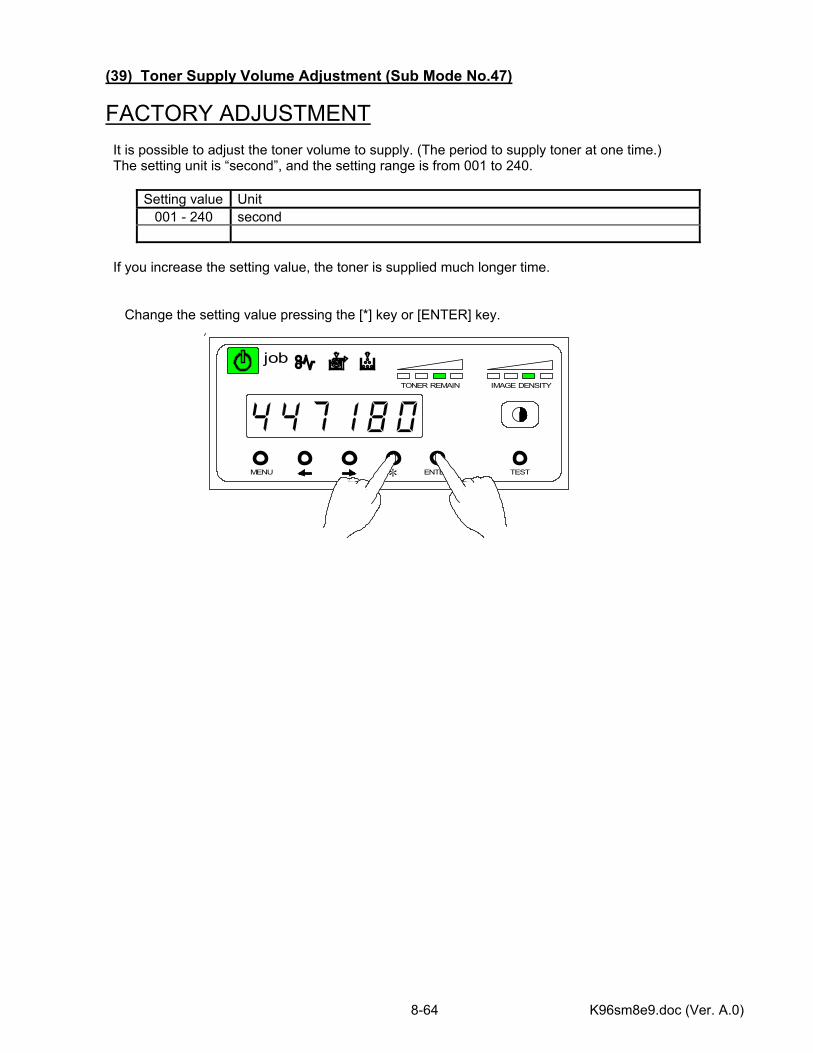
K96sm8e9.doc (Ver. A.0) 8-64
MENU ENTER TEST
TONER REMAIN IMAGE DENSITY
job
*
(39) Toner Supply Volume Adjustment (Sub Mode No.47)
FACTORY ADJUSTMENT It is possible to adjust the toner volume to supply. (The period to supply toner at one time.) The setting unit is “second”, and the setting range is from 001 to 240.
Setting value Unit 001 - 240 second
If you increase the setting value, the toner is supplied much longer time. Change the setting value pressing the [*] key or [ENTER] key.
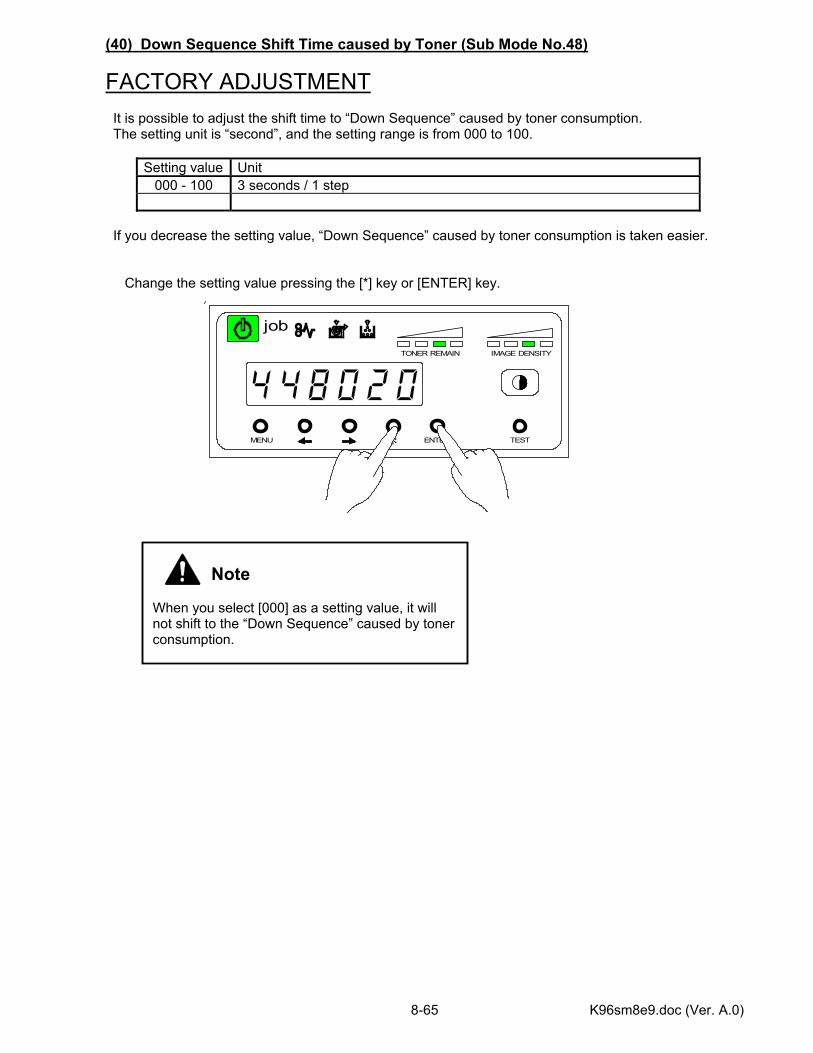
K96sm8e9.doc (Ver. A.0) 8-65
MENU ENTER TEST
TONER REMAIN IMAGE DENSITY
job
*
(40) Down Sequence Shift Time caused by Toner (Sub Mode No.48)
FACTORY ADJUSTMENT It is possible to adjust the shift time to “Down Sequence” caused by toner consumption. The setting unit is “second”, and the setting range is from 000 to 100.
Setting value Unit 000 - 100 3 seconds / 1 step
If you decrease the setting value, “Down Sequence” caused by toner consumption is taken easier. Change the setting value pressing the [*] key or [ENTER] key.
Note When you select [000] as a setting value, it will not shift to the “Down Sequence” caused by toner consumption.
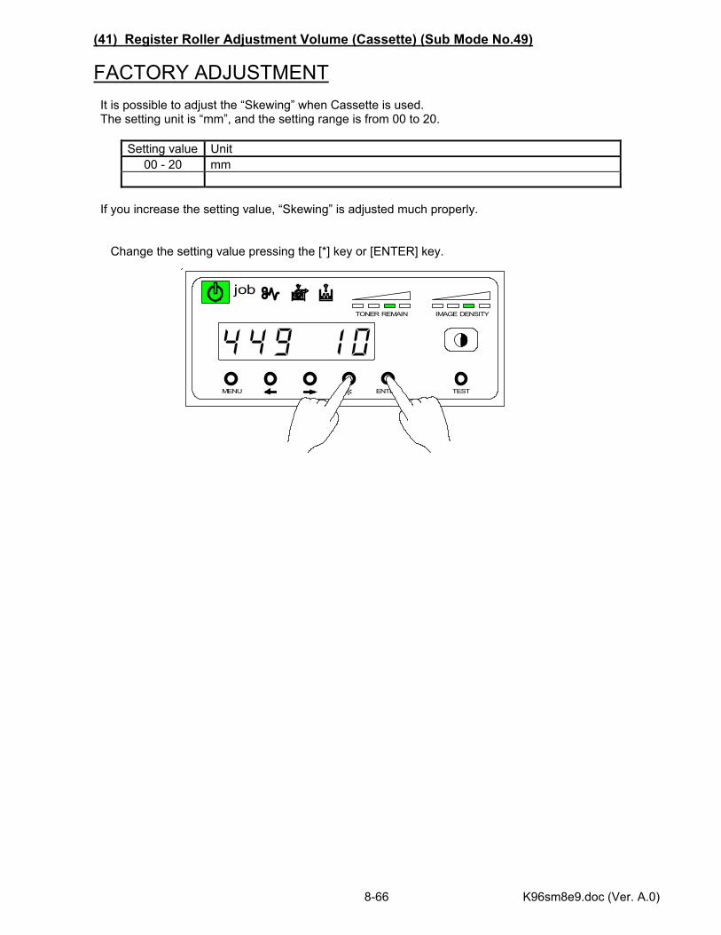
K96sm8e9.doc (Ver. A.0) 8-66
MENU ENTER TEST
TONER REMAIN IMAGE DENSITY
job
*
(41) Register Roller Adjustment Volume (Cassette) (Sub Mode No.49)
FACTORY ADJUSTMENT It is possible to adjust the “Skewing” when Cassette is used. The setting unit is “mm”, and the setting range is from 00 to 20.
Setting value Unit 00 - 20 mm
If you increase the setting value, “Skewing” is adjusted much properly. Change the setting value pressing the [*] key or [ENTER] key.
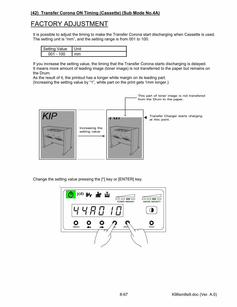
K96sm8e9.doc (Ver. A.0) 8-67
MENU ENTER TEST
TONER REMAIN IMAGE DENSITY
job
*
(42) Transfer Corona ON Timing (Cassette) (Sub Mode No.4A)
FACTORY ADJUSTMENT It is possible to adjust the timing to make the Transfer Corona start discharging when Cassette is used. The setting unit is “mm”, and the setting range is from 001 to 100.
Setting Value Unit 001 - 100 mm
If you increase the setting value, the timing that the Transfer Corona starts discharging is delayed. It means more amount of leading image (toner image) is not transferred to the paper but remains on the Drum. As the result of it, the printout has a longer white margin on its leading part. (Increasing the setting value by “1”, white part on the print gets 1mm longer.) Change the setting value pressing the [*] key or [ENTER] key.
Increasing thesetting value
Transfer Charger starts chargingat this point.
This part of toner image is not transferedfrom the Drum to the paper.

K96sm8e9.doc (Ver. A.0) 8-68
MENU ENTER TEST
TONER REMAIN IMAGE DENSITY
job
*
(43) Transfer Corona OFF Timing (Cassette) (Sub Mode No.4b)
FACTORY ADJUSTMENT It is possible to adjust the timing to make the Transfer Corona stop discharging when Cassette is used. The setting unit is “mm”, and the setting range is from 001 to 300.
Setting Value Unit 001 - 300 mm
If you decrease the setting value, the timing that the Transfer Corona stops discharging becomes earlier. It means more amount of trailing image (toner image) is not transferred to the paper but remains on the Drum. As the result of it, the printout has a longer white margin on its trailing part. (Decreasing the setting value by “1”, white part on the print gets 1mm longer.) Change the setting value pressing the [*] key or [ENTER] key.
Decreasing thesetting value
Transfer Charger stops chargingat this point.
This part of toner image is not transferedfrom the Drum to the paper.
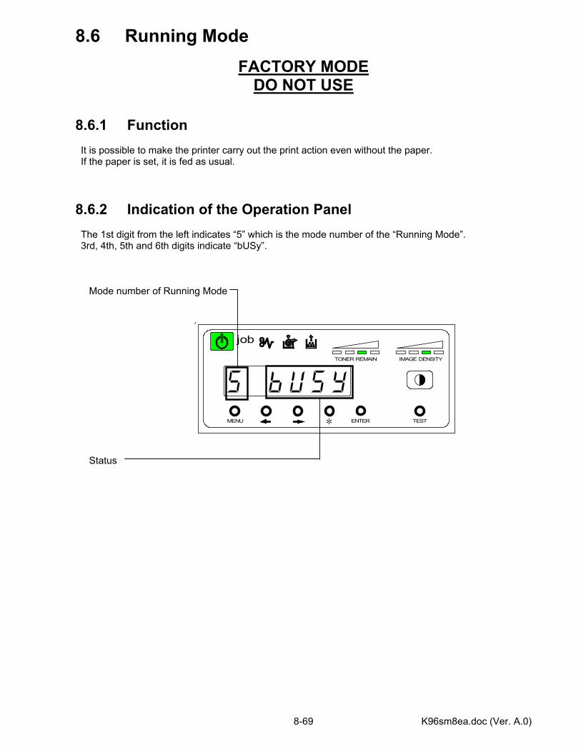
K96sm8ea.doc (Ver. A.0) 8-69
MENU ENTER TEST
TONER REMAIN IMAGE DENSITY
job
*
8.6 Running Mode
FACTORY MODE DO NOT USE
8.6.1 Function It is possible to make the printer carry out the print action even without the paper. If the paper is set, it is fed as usual. 8.6.2 Indication of the Operation Panel The 1st digit from the left indicates “5” which is the mode number of the “Running Mode”. 3rd, 4th, 5th and 6th digits indicate “bUSy”. Mode number of Running Mode
Status
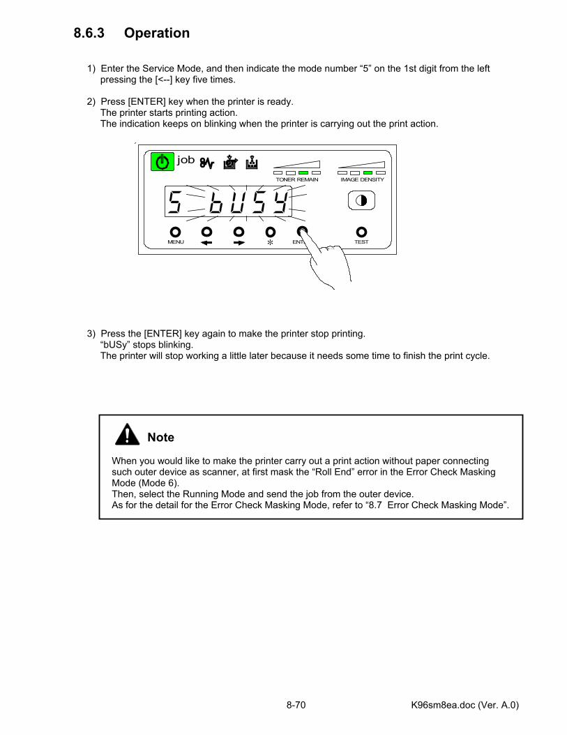
K96sm8ea.doc (Ver. A.0) 8-70
MENU ENTER TEST
TONER REMAIN IMAGE DENSITY
job
*
8.6.3 Operation 1) Enter the Service Mode, and then indicate the mode number “5” on the 1st digit from the left pressing the [<--] key five times. 2) Press [ENTER] key when the printer is ready. The printer starts printing action. The indication keeps on blinking when the printer is carrying out the print action. 3) Press the [ENTER] key again to make the printer stop printing. “bUSy” stops blinking. The printer will stop working a little later because it needs some time to finish the print cycle.
Note When you would like to make the printer carry out a print action without paper connecting such outer device as scanner, at first mask the “Roll End” error in the Error Check Masking Mode (Mode 6). Then, select the Running Mode and send the job from the outer device. As for the detail for the Error Check Masking Mode, refer to “8.7 Error Check Masking Mode”.
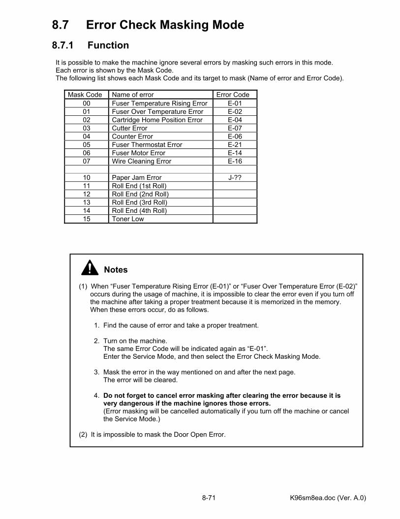
K96sm8ea.doc (Ver. A.0) 8-71
8.7 Error Check Masking Mode 8.7.1 Function It is possible to make the machine ignore several errors by masking such errors in this mode. Each error is shown by the Mask Code. The following list shows each Mask Code and its target to mask (Name of error and Error Code).
Mask Code Name of error Error Code 00 Fuser Temperature Rising Error E-01 01 Fuser Over Temperature Error E-02 02 Cartridge Home Position Error E-04 03 Cutter Error E-07 04 Counter Error E-06 05 Fuser Thermostat Error E-21 06 Fuser Motor Error E-14 07 Wire Cleaning Error E-16
10 Paper Jam Error J-?? 11 Roll End (1st Roll) 12 Roll End (2nd Roll) 13 Roll End (3rd Roll) 14 Roll End (4th Roll) 15 Toner Low
Notes (1) When “Fuser Temperature Rising Error (E-01)” or “Fuser Over Temperature Error (E-02)” occurs during the usage of machine, it is impossible to clear the error even if you turn off the machine after taking a proper treatment because it is memorized in the memory. When these errors occur, do as follows. 1. Find the cause of error and take a proper treatment. 2. Turn on the machine. The same Error Code will be indicated again as “E-01”. Enter the Service Mode, and then select the Error Check Masking Mode. 3. Mask the error in the way mentioned on and after the next page. The error will be cleared. 4. Do not forget to cancel error masking after clearing the error because it is very dangerous if the machine ignores those errors. (Error masking will be cancelled automatically if you turn off the machine or cancel the Service Mode.) (2) It is impossible to mask the Door Open Error.
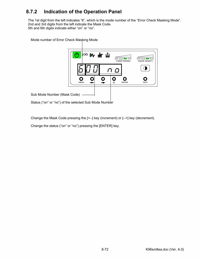
K96sm8ea.doc (Ver. A.0) 8-72
MENU ENTER TEST
TONER REMAIN IMAGE DENSITY
job
*
8.7.2 Indication of the Operation Panel The 1st digit from the left indicates “6”, which is the mode number of the “Error Check Masking Mode”. 2nd and 3rd digits from the left indicate the Mask Code. 5th and 6th digits indicate either “on” or “no”. Mode number of Error Check Masking Mode Sub Mode Number (Mask Code)
Status (“on” or “no”) of the selected Sub Mode Number Change the Mask Code pressing the [<--] key (increment) or [-->] key (decrement). Change the status (“on” or “no”) pressing the [ENTER] key.
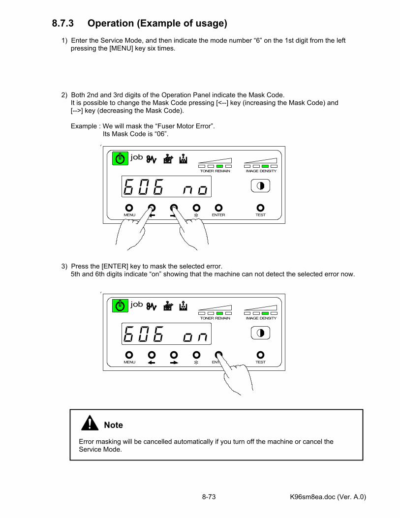
K96sm8ea.doc (Ver. A.0) 8-73
MENU ENTER TEST
TONER REMAIN IMAGE DENSITY
job
*
MENU ENTER TEST
TONER REMAIN IMAGE DENSITY
job
*
8.7.3 Operation (Example of usage) 1) Enter the Service Mode, and then indicate the mode number “6” on the 1st digit from the left pressing the [MENU] key six times. 2) Both 2nd and 3rd digits of the Operation Panel indicate the Mask Code. It is possible to change the Mask Code pressing [<--] key (increasing the Mask Code) and [-->] key (decreasing the Mask Code). Example : We will mask the “Fuser Motor Error”. Its Mask Code is “06”.
3) Press the [ENTER] key to mask the selected error. 5th and 6th digits indicate “on” showing that the machine can not detect the selected error now.
Note Error masking will be cancelled automatically if you turn off the machine or cancel the Service Mode.
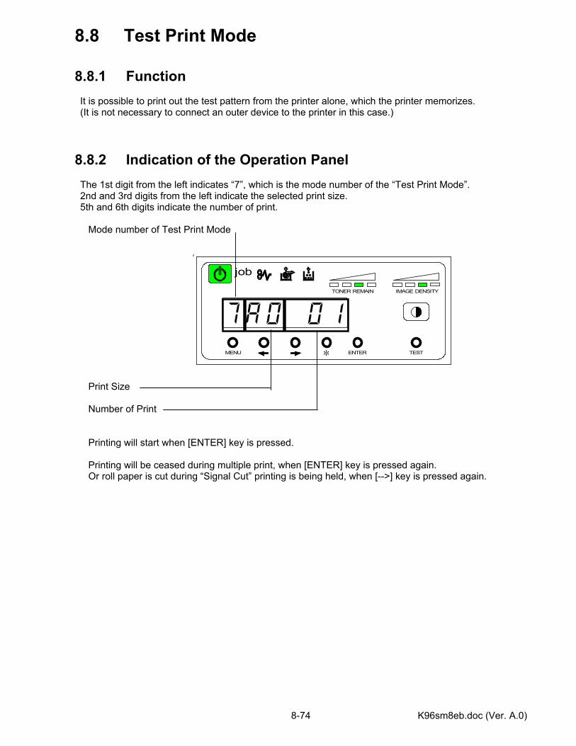
K96sm8eb.doc (Ver. A.0) 8-74
MENU ENTER TEST
TONER REMAIN IMAGE DENSITY
job
*
8.8 Test Print Mode 8.8.1 Function It is possible to print out the test pattern from the printer alone, which the printer memorizes. (It is not necessary to connect an outer device to the printer in this case.) 8.8.2 Indication of the Operation Panel The 1st digit from the left indicates “7”, which is the mode number of the “Test Print Mode”. 2nd and 3rd digits from the left indicate the selected print size. 5th and 6th digits indicate the number of print. Mode number of Test Print Mode
Print Size Number of Print Printing will start when [ENTER] key is pressed. Printing will be ceased during multiple print, when [ENTER] key is pressed again. Or roll paper is cut during “Signal Cut” printing is being held, when [-->] key is pressed again.
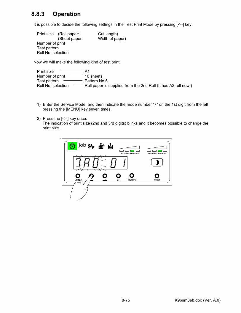
K96sm8eb.doc (Ver. A.0) 8-75
MENU ENTER TEST
TONER REMAIN IMAGE DENSITY
job
*
8.8.3 Operation It is possible to decide the following settings in the Test Print Mode by pressing [<--] key. Print size (Roll paper: Cut length) (Sheet paper: Width of paper) Number of print Test pattern Roll No. selection Now we will make the following kind of test print. Print size A1 Number of print 10 sheets Test pattern Pattern No.5 Roll No. selection Roll paper is supplied from the 2nd Roll (It has A2 roll now.) 1) Enter the Service Mode, and then indicate the mode number “7” on the 1st digit from the left pressing the [MENU] key seven times. 2) Press the [<--] key once. The indication of print size (2nd and 3rd digits) blinks and it becomes possible to change the print size.
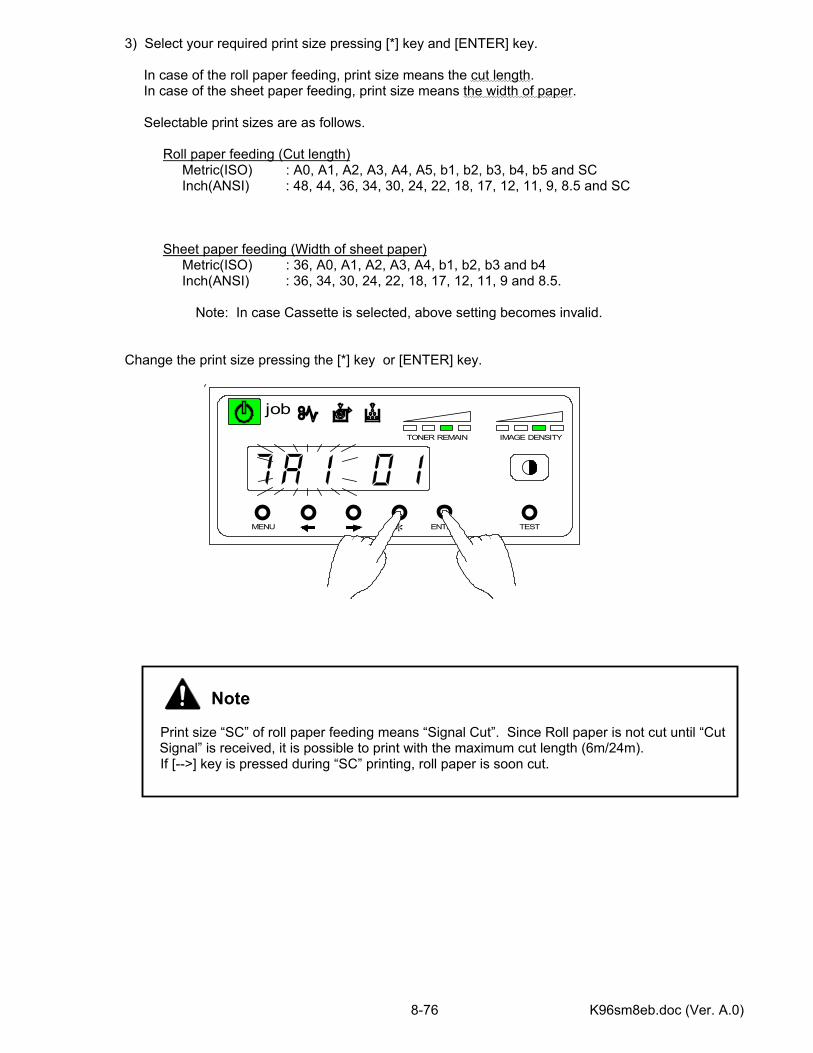
K96sm8eb.doc (Ver. A.0) 8-76
MENU ENTER TEST
TONER REMAIN IMAGE DENSITY
job
*
3) Select your required print size pressing [*] key and [ENTER] key. In case of the roll paper feeding, print size means the cut length. In case of the sheet paper feeding, print size means the width of paper. Selectable print sizes are as follows. Roll paper feeding (Cut length) Metric(ISO) : A0, A1, A2, A3, A4, A5, b1, b2, b3, b4, b5 and SC Inch(ANSI) : 48, 44, 36, 34, 30, 24, 22, 18, 17, 12, 11, 9, 8.5 and SC Sheet paper feeding (Width of sheet paper) Metric(ISO) : 36, A0, A1, A2, A3, A4, b1, b2, b3 and b4 Inch(ANSI) : 36, 34, 30, 24, 22, 18, 17, 12, 11, 9 and 8.5. Note: In case Cassette is selected, above setting becomes invalid. Change the print size pressing the [*] key or [ENTER] key.
Note Print size “SC” of roll paper feeding means “Signal Cut”. Since Roll paper is not cut until “Cut Signal” is received, it is possible to print with the maximum cut length (6m/24m).
If [-->] key is pressed during “SC” printing, roll paper is soon cut.
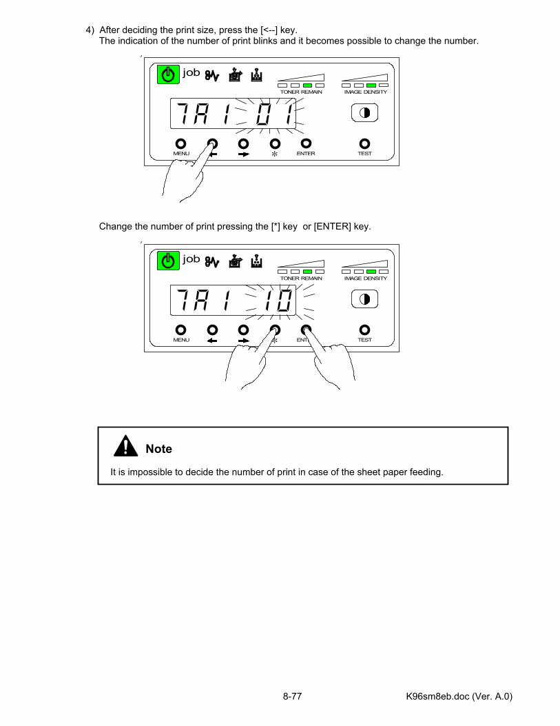
K96sm8eb.doc (Ver. A.0) 8-77
MENU ENTER TEST
TONER REMAIN IMAGE DENSITY
job
*
MENU ENTER TEST
TONER REMAIN IMAGE DENSITY
job
*
4) After deciding the print size, press the [<--] key. The indication of the number of print blinks and it becomes possible to change the number.
Change the number of print pressing the [*] key or [ENTER] key.
Note It is impossible to decide the number of print in case of the sheet paper feeding.
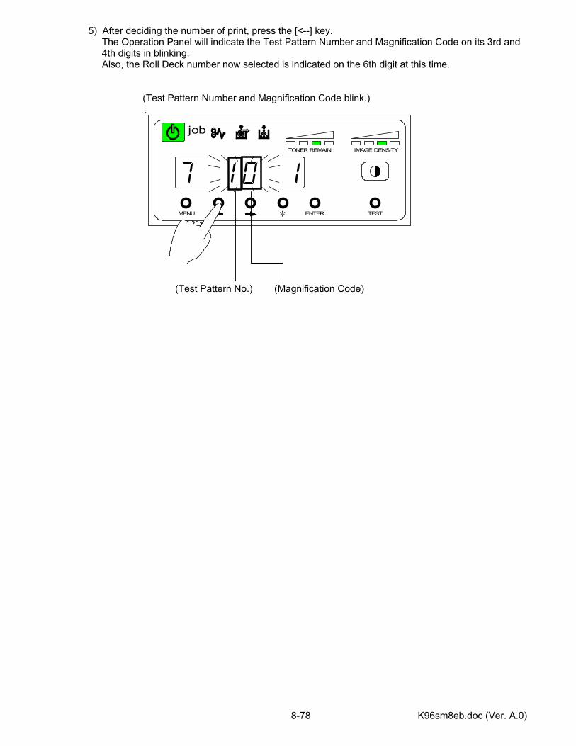
K96sm8eb.doc (Ver. A.0) 8-78
MENU ENTER TEST
TONER REMAIN IMAGE DENSITY
job
*
5) After deciding the number of print, press the [<--] key. The Operation Panel will indicate the Test Pattern Number and Magnification Code on its 3rd and 4th digits in blinking. Also, the Roll Deck number now selected is indicated on the 6th digit at this time. (Test Pattern Number and Magnification Code blink.)
(Test Pattern No.) (Magnification Code)
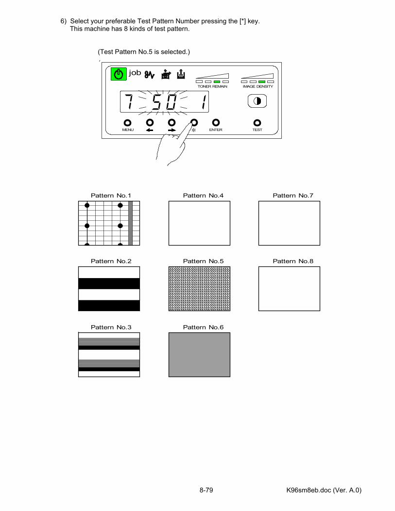
K96sm8eb.doc (Ver. A.0) 8-79
MENU ENTER TEST
TONER REMAIN IMAGE DENSITY
job
*
6) Select your preferable Test Pattern Number pressing the [*] key. This machine has 8 kinds of test pattern. (Test Pattern No.5 is selected.)
Pattern No.1
Pattern No.2
Pattern No.3
Pattern No.4
Pattern No.5
Pattern No.6
Pattern No.7
Pattern No.8
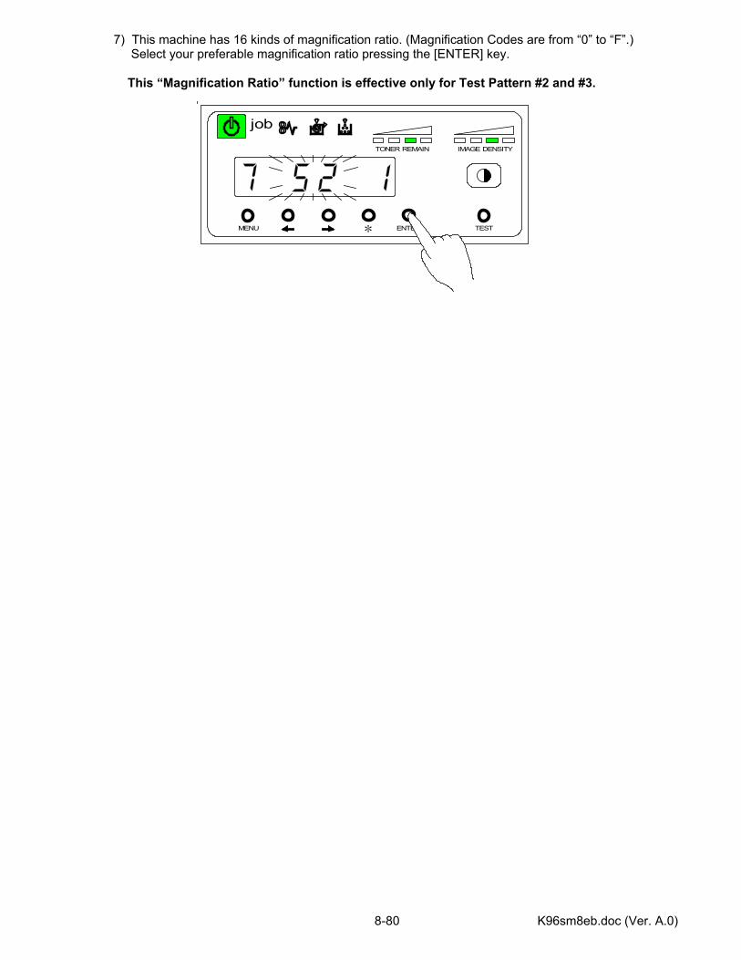
K96sm8eb.doc (Ver. A.0) 8-80
MENU ENTER TEST
TONER REMAIN IMAGE DENSITY
job
*
7) This machine has 16 kinds of magnification ratio. (Magnification Codes are from “0” to “F”.) Select your preferable magnification ratio pressing the [ENTER] key. This “Magnification Ratio” function is effective only for Test Pattern #2 and #3.
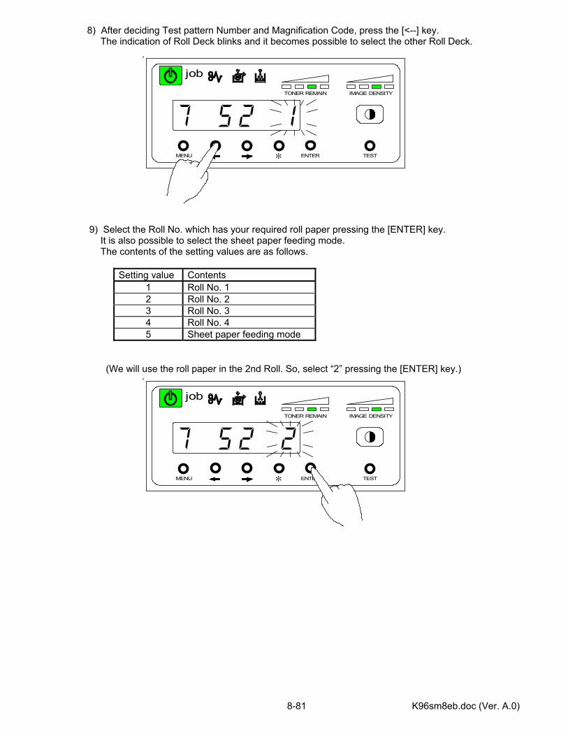
K96sm8eb.doc (Ver. A.0) 8-81
MENU ENTER TEST
TONER REMAIN IMAGE DENSITY
job
*
MENU ENTER TEST
TONER REMAIN IMAGE DENSITY
job
*
8) After deciding Test pattern Number and Magnification Code, press the [<--] key. The indication of Roll Deck blinks and it becomes possible to select the other Roll Deck.
9) Select the Roll No. which has your required roll paper pressing the [ENTER] key.
It is also possible to select the sheet paper feeding mode. The contents of the setting values are as follows.
Setting value Contents 1 Roll No. 1 2 Roll No. 2 3 Roll No. 3 4 Roll No. 4 5 Sheet paper feeding mode
(We will use the roll paper in the 2nd Roll. So, select “2” pressing the [ENTER] key.)
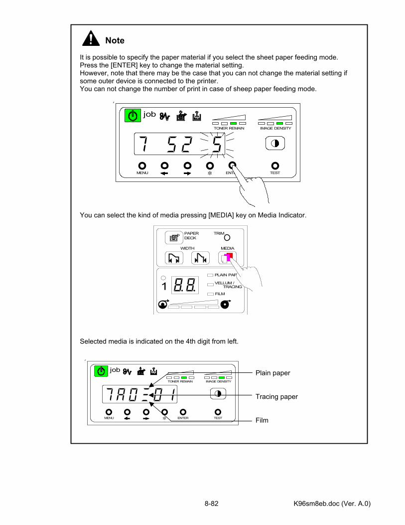
K96sm8eb.doc (Ver. A.0) 8-82
Note It is possible to specify the paper material if you select the sheet paper feeding mode. Press the [ENTER] key to change the material setting. However, note that there may be the case that you can not change the material setting if some outer device is connected to the printer. You can not change the number of print in case of sheep paper feeding mode. You can select the kind of media pressing [MEDIA] key on Media Indicator. Selected media is indicated on the 4th digit from left. Plain paper Tracing paper Film
MENU ENTER TEST
TONER REMAIN IMAGE DENSITY
job
*
PAPER TRIMDECK
WIDTH MEDIA
PLAIN PAPAR
VELLUM /TRACING
FILM1
MENU ENTER TEST
TONER REMAIN IMAGE DENSITY
job
*
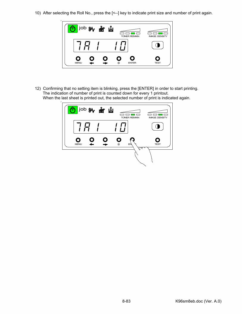
K96sm8eb.doc (Ver. A.0) 8-83
MENU ENTER TEST
TONER REMAIN IMAGE DENSITY
job
*
10) After selecting the Roll No., press the [<--] key to indicate print size and number of print again. 12) Confirming that no setting item is blinking, press the [ENTER] in order to start printing. The indication of number of print is counted down for every 1 printout. When the last sheet is printed out, the selected number of print is indicated again.
MENU ENTER TEST
TONER REMAIN IMAGE DENSITY
job
*
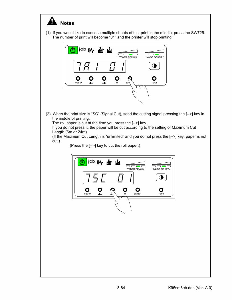
K96sm8eb.doc (Ver. A.0) 8-84
Notes (1) If you would like to cancel a multiple sheets of test print in the middle, press the SW725. The number of print will become “01” and the printer will stop printing. (2) When the print size is “SC” (Signal Cut), send the cutting signal pressing the [-->] key in the middle of printing. The roll paper is cut at the time you press the [-->] key. If you do not press it, the paper will be cut according to the setting of Maximum Cut Length (6m or 24m). (If the Maximum Cut Length is “unlimited” and you do not press the [-->] key, paper is not cut.) (Press the [-->] key to cut the roll paper.)
MENU ENTER TEST
TONER REMAIN IMAGE DENSITY
job
*
MENU ENTER TEST
TONER REMAIN IMAGE DENSITY
job
*
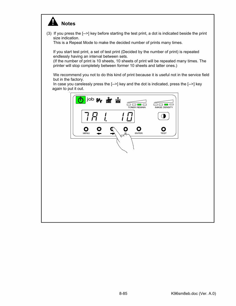
K96sm8eb.doc (Ver. A.0) 8-85
Notes (3) If you press the [-->] key before starting the test print, a dot is indicated beside the print size indication. This is a Repeat Mode to make the decided number of prints many times. If you start test print, a set of test print (Decided by the number of print) is repeated endlessly having an interval between sets. (If the number of print is 10 sheets, 10 sheets of print will be repeated many times. The printer will stop completely between former 10 sheets and latter ones.) We recommend you not to do this kind of print because it is useful not in the service field but in the factory. In case you carelessly press the [-->] key and the dot is indicated, press the [-->] key
again to put it out.
MENU ENTER TEST
TONER REMAIN IMAGE DENSITY
job
*
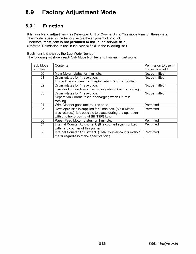
K96sm8ec(Ver.A.0) 8-86
8.9 Factory Adjustment Mode 8.9.1 Function It is possible to adjust items as Developer Unit or Corona Units. This mode turns on these units. This mode is used in the factory before the shipment of product. Therefore, most item is not permitted to use in the service field. (Refer to “Permission to use in the service field” in the following list.) Each item is shown by the Sub Mode Number. The following list shows each Sub Mode Number and how each part works.
Sub Mode Number
Contents Permission to use in the service field
00 Main Motor rotates for 1 minute. Not permitted 01 Drum rotates for 1 revolution.
Image Corona takes discharging when Drum is rotating. Not permitted
02 Drum rotates for 1 revolution. Transfer Corona takes discharging when Drum is rotating.
Not permitted
03 Drum rotates for 1 revolution. Separation Corona takes discharging when Drum is rotating.
Not permitted
04 Wire Cleaner goes and returns once. Permitted 05 Developer Bias is supplied for 3 minutes. (Main Motor
also rotates.) It is possible to cease during the operation with another pressing of [ENTER] key.
Permitted
06 Paper Feed Motor rotates for 1 minute. Permitted 07 Internal Counter Adjustment. (It is counted synchronized
with hard counter of this printer.) Permitted
08 Internal Counter Adjustment. (Total counter counts every 1 meter regardless of the specification.)
Permitted
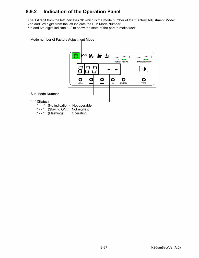
K96sm8ec(Ver.A.0) 8-87
MENU ENTER TEST
TONER REMAIN IMAGE DENSITY
job
*
8.9.2 Indication of the Operation Panel The 1st digit from the left indicates “8” which is the mode number of the “Factory Adjustment Mode”. 2nd and 3rd digits from the left indicate the Sub Mode Number. 5th and 6th digits indicate “- -” to show the state of the part to make work. Mode number of Factory Adjustment Mode
Sub Mode Number “- -“ (Status) “ “ (No indication): Not operable “ - - “ (Staying ON): Not working “ - - “ (Flashing): Operating
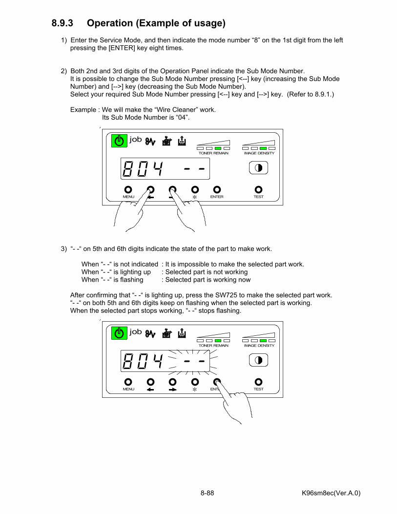
K96sm8ec(Ver.A.0) 8-88
MENU ENTER TEST
TONER REMAIN IMAGE DENSITY
job
*
MENU ENTER TEST
TONER REMAIN IMAGE DENSITY
job
*
8.9.3 Operation (Example of usage) 1) Enter the Service Mode, and then indicate the mode number “8” on the 1st digit from the left pressing the [ENTER] key eight times. 2) Both 2nd and 3rd digits of the Operation Panel indicate the Sub Mode Number. It is possible to change the Sub Mode Number pressing [<--] key (increasing the Sub Mode Number) and [-->] key (decreasing the Sub Mode Number). Select your required Sub Mode Number pressing [<--] key and [-->] key. (Refer to 8.9.1.) Example : We will make the “Wire Cleaner” work. Its Sub Mode Number is “04”.
3) “- -“ on 5th and 6th digits indicate the state of the part to make work. When “- -“ is not indicated : It is impossible to make the selected part work. When “- -“ is lighting up : Selected part is not working When “- -“ is flashing : Selected part is working now After confirming that “- -“ is lighting up, press the SW725 to make the selected part work. “- -“ on both 5th and 6th digits keep on flashing when the selected part is working. When the selected part stops working, “- -“ stops flashing.

K96sm8ec(Ver.A.0) 8-89
MENU ENTER TEST
TONER REMAIN IMAGE DENSITY
job
*
MENU ENTER TEST
TONER REMAIN IMAGE DENSITY
job
*
8.9.4 Internal Counter Adjustment (Sub Mode 07 & 08) 1) Enter the Service Mode, and then indicate the mode number “8” on the 1st digit from the left pressing the [MENU] key eight times. 2) Select your required Sub Mode Number pressing [<--] key and [-->] key. 3) “- -“ on 5th and 6th digits indicate the state of the part to make work.
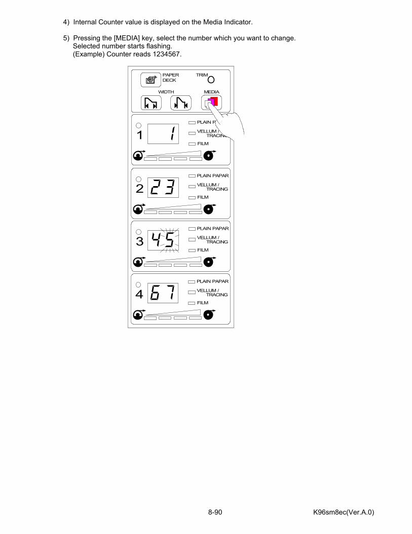
K96sm8ec(Ver.A.0) 8-90
4) Internal Counter value is displayed on the Media Indicator. 5) Pressing the [MEDIA] key, select the number which you want to change. Selected number starts flashing. (Example) Counter reads 1234567.
PAPER TRIMDECK
WIDTH MEDIA
PLAIN PAPAR
VELLUM /TRACING
FILM1
PLAIN PAPAR
VELLUM /TRACING
FILM2
PLAIN PAPAR
VELLUM /TRACING
FILM3
PLAIN PAPAR
VELLUM /TRACING
FILM4
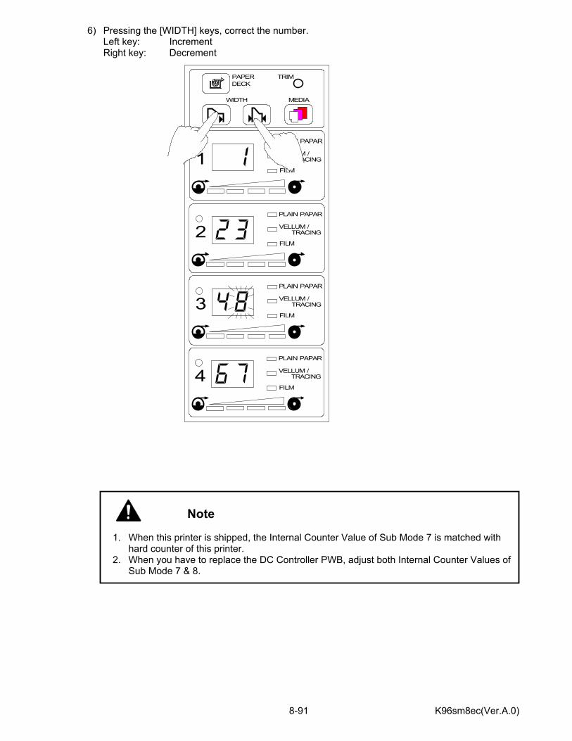
K96sm8ec(Ver.A.0) 8-91
6) Pressing the [WIDTH] keys, correct the number. Left key: Increment Right key: Decrement
Note
1. When this printer is shipped, the Internal Counter Value of Sub Mode 7 is matched with
hard counter of this printer. 2. When you have to replace the DC Controller PWB, adjust both Internal Counter Values of
Sub Mode 7 & 8.
PAPER TRIMDECK
WIDTH MEDIA
PLAIN PAPAR
VELLUM /TRACING
FILM1
PLAIN PAPAR
VELLUM /TRACING
FILM2
PLAIN PAPAR
VELLUM /TRACING
FILM3
PLAIN PAPAR
VELLUM /TRACING
FILM4
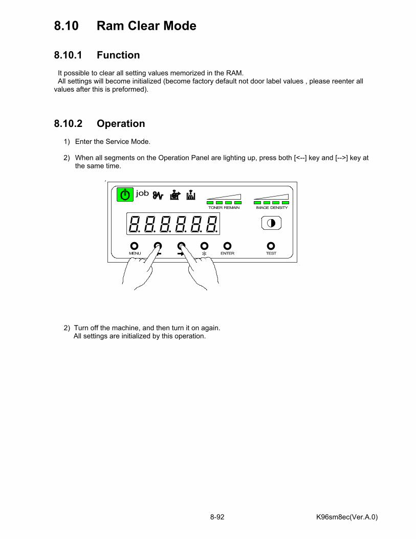
K96sm8ec(Ver.A.0) 8-92
8.10 Ram Clear Mode 8.10.1 Function It possible to clear all setting values memorized in the RAM. All settings will become initialized (become factory default not door label values , please reenter all values after this is preformed). 8.10.2 Operation
1) Enter the Service Mode. 2) When all segments on the Operation Panel are lighting up, press both [<--] key and [-->] key at
the same time. 2) Turn off the machine, and then turn it on again. All settings are initialized by this operation.
MENU ENTER TEST
TONER REMAIN IMAGE DENSITY
job
*