Kingsbury Equalizing Bearings, Three Shoe and Six … · Equalizing Bearings Three-Shoe and...
42
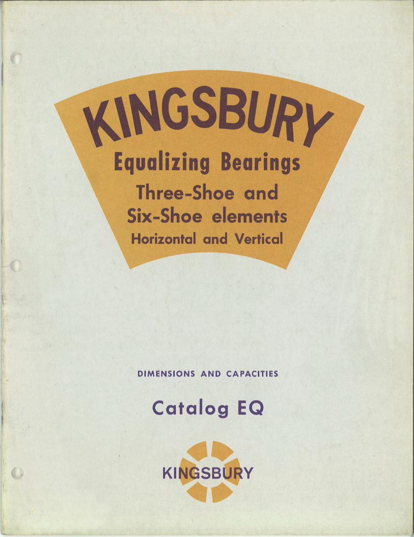
f Equalizing Bearings Three-Shoe and Six-Shoe elements Horizontal and Vertical DIMENSIONS AND CAPACITIES Catalog EQ
Transcript of Kingsbury Equalizing Bearings, Three Shoe and Six … · Equalizing Bearings Three-Shoe and...
f
Equalizing Bearings Three-Shoe and
Six-Shoe elements Horizontal and Vertical
DIMENSIONS AND CAPACITIES
Catalog EQ
I y
E UALIZI G BEAR! GS
Three--Shoe and Six--Shoe elements
Horizontal and Vertical
DIMENSIONS
and
CAPACITIES
CATALOG EQ
KINGSBURY MACHINE WORKS, INC.
PRINTED IN U.S.A.
1986-3M
10385 DRUMMOND ROAD
PHILADELPHIA, PENNA. 19154
CONTENTS PAGE
Foreword.. . . . . . . . . . . . . . . . . . . . . . . . . . . . . . . . . . . . . . . . . . . . . . .. 5
Typical Uses of Equalizing Bearings. . . . . . . . . . . . . . . . . . . . . . . .. 6 Special Uses ... Basic Elemen ts. . . . . . . . . . . . . . . . . . . . . . . . . . .. 7
Standard Three-shoe and Six-shoe Bearing Parts. . . . . . . . . . . . .. 8 Standard Assem blies: Three-shoe and Six-shoe. . . . . . . . . . . . . . .. 9 Symbols for Standard Assemblies ............................ 12 High Speed Bearings for Turbines and Blowers ................ 13
Lubrication, Cooling and Housing Design ..................... 14 Thrust Capacity Tables .................................... 16 Maximum Speeds for Air-Cooled Operation (Table)........... 17 Friction Losses and Oil Requirements (Chart) ................. 18 Choosing the Style and Size. . . . . . . . . . . . . . . . . . . . . . . . . . . . . . .. 19 Standard Dimension Lists ................................ 20-29
JH and JHJ, page 20 J and JJ, page 21 BH and BHB, page 22 Band BB, page 23 NH and NHN, page 24 Nand NN, page 25 JHN, page 26 KV and JV, page 27 LV and NV, page 28 KBV and BV, page 29
Standard Oil Control Ring Bearings (Dimensions) ........... " 30 Special Horizon tal Bearings, selected (Dimensions) . . . . . . . . . . .. 31 Shaft Sizes for Standard Horizon tal Bearings. . . . . . . . . . . . . . . .. 32 Shaft and Oil Retainer Sizes for Vertical Bearings. . . . . . . . . . . .. 33 Special Two-Diameter Thrust Bearings (Dimensions) .......... 34 End Play (Chart and Text) ................................. 35 Typical Moun tings and Some Specials. . . . . . . . . . . . . . . . . . . . . .. 36 Spare Parts. . . . . . . . . . . . . . . . . . . . . . . . . . . . . . . . . . . . . . . . . . . . . .. 41 Data Needed for Ordering .................................. 41 Standard Guaran tee ....................................... 41
4
FOREWORD
Kingsbury "Equalizing" Thrust Bearings are self-adjusting so that the thrust load is equally divided among all the shoes on either side of the thrust collar. They are to be distinguished from Kingsbury "Adjustable" Thrust Bearings, in which each shoe is backed by its own "jack screw," which must be separately adjusted. Since the oil films may be no more than one or two thousandths of an inch thick, automatic equalization of load and film thickness is a useful assurance that the bearing can be loaded to its theoretical capacity.
These "equalizing" bearings also compensate for slight misalignmen t or deflection of housings.
This Catalog covers only the standard sizes of three-shoe and six-shoe internal parts, which are by far most used. Those parts are intended to be incorporated by the machinery builder into housings of his own manufacture. They are applicable to both horizontal and vertical shafts, under a great variety of speed and load conditions, with proper provision for oil circulation and for cooling.
In certain small sizes, both three- and six-shoe bearings have been standardized with 'the addition of an "Oil Control Ring" for high-speed application to steam turbines and blowers. This feature controls the oil flow in such a way as to minimize power loss due to churning of the oil at turbine speeds.
Some more common applications of Kingsbury Thrust Bearings are mentioned on page 6: others are suggested. With the growing use of higher speeds and loads, Kingsburys offer performance scarcely attainable with other types of thrust bearings.
Because of the possibility of minor changes, or of changes to meet special conditions, the figures in the various Dimension Lists should be confirmed by us before starting actual construction.
Explanation of the basic Kingsbury principle of wedge-shaped oil films, automatically self-renewed and preventing metallic contact and wear, will be found in other booklets.
5
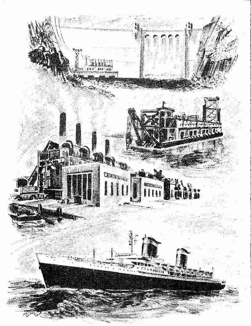
Typical Uses of Kingsbury Equalizing Thrust Bearings
Kingsbury Thrust Bearings are most used where loads are heavy and speeds are high, and where indefinitely long life is desired with minimum attention and freedom from repairs. Those characteristics follow naturally from the Kingsbury principle of "floating" the load on moving films of oil, by which the working surfaces are completely separated while running.
The following classes of service exemplify the above requirements. In each group, reference is made to the pages and tables wherein the particular "styles" of Kingsbury Bearings mentioned are shown.
Horizontal Shafts
Ship Propulsion
Most reduction-geared drives employ standard six-shoe bearings built into the forward end of the gear housing, as in Figures 23 and 24. See Style BHB, page 29; also, for smaller vessels, Style JHJ in sizes up to 17 inches diameter of thrust collar,* page 28. Occasionally the thrust bearing parts are located in the after end of the gear housing, or sometimes separately, in a specially-built housing on the line shaft. In these latter cases, the shaft size often requires using eight large-bore shoes instead of six standard shoes. Eight-shoe bearings are special, and are not listed here. We should be consulted.
The two-shoe "adjustable" bearings often used in smaller vessels are not included here: they are to be found in other literature.
Horizontal Centrifugal Pumps and Water Turbines
For boiler feed and similar pumps we usually supply complete self-lubricating bearings, including housings, for attachment to the customer's pump body. These are described in other literature.
However, we can furnish standard internal parts with six or three shoes to be built into the customer's housings and lubricated from an outside source. See Styles JHJ, JHN, and NHN, pages 9 and 11.
Horizontal Steam Turbines, Gas Turbines, Compressors and Blowers
Equalizing three- and six-shoe bearings for these high-speed applications are equipped with Oil Con trol Rings to minimize the power loss from oil churning at high rotative speeds. See page 13.
Vertical Shafts
Vertical Electric Motors
These include motors for deep-well pumps, drydock unwatering pumps, hot-well pumps, and miscellaneous pumps for water works and sewerage; also electrical condensers. The standard three- and six-shoe equalizing elements, in sizes 5 inches to 17 inches for vertical loads from 1000 to about 70,000 lbs., are suitable for most pump drives. See Styles NV, LV, JV and KV, pages 10 and 27 to 28. Style KV, page 10, is most often used. Hydroelectric machinery and large pump motors often use the larger six-shoe bearings, Style KBV. See page 29.
Vertical Hydroelectric Generators
Equalizing six-shoe bearings, Styles KBV and BV (page 29) are standardized up to 45 inches size. Larger sizes are often used: we shall be glad to make suitable recommendations.
Vertical Steam Turbines and Blowers
These use Style NV or JV internal parts (pages 9 and 10) in connection with special grooving in the housing to perform the function of an Oil Control Ring. The housing designs are special: we should be consulted.
Other Uses
In addition to the "typical" uses named above, Kingsbury equalizing bearings are employed in a great variety of miscellaneous and special uses, some of which are named on page 7. We are always glad to discuss new and unusual applications, including non-standard details if needed.
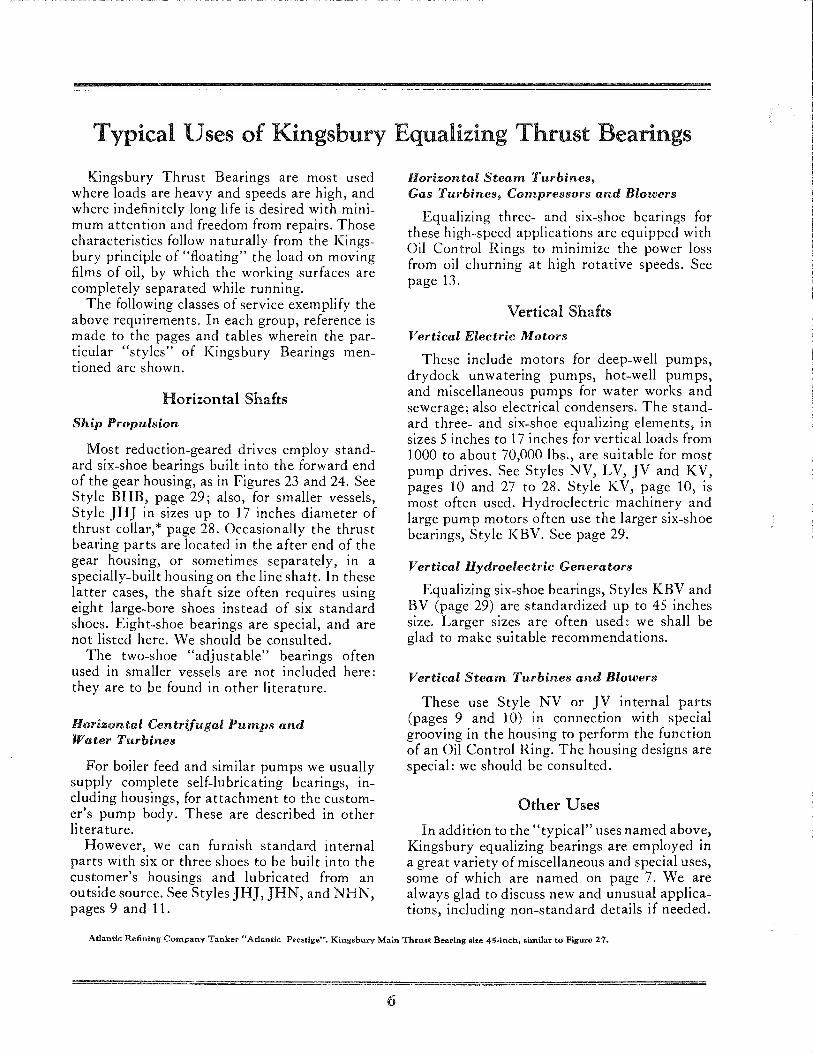
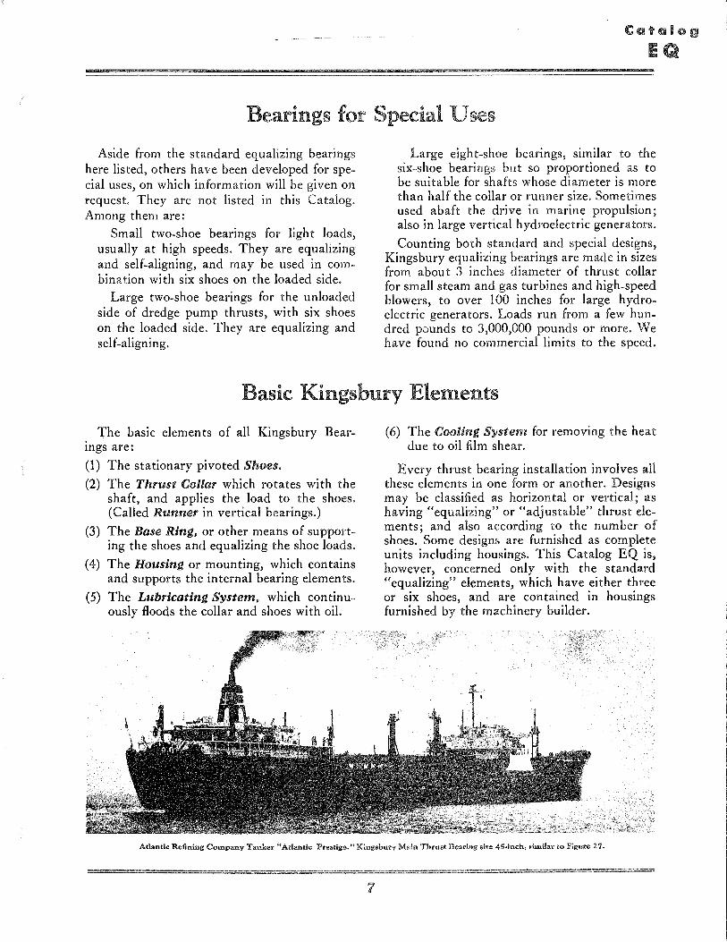
Atlantic Refining Company Tanker HAtlantic Prestige". Kingsbury Main Thrust Bearing size 45 .. inch, similar to Figure 27.
6
Bearings for Special Uses
Aside from the standard equalizing bearings here listed, others have been developed for special uses, on which information will be given on request. They are not listed in this Catalog. Among them are:
Small two-shoe bearings for light loads, usually at high speeds. They are equalizing and self-aligning, and may be used in combination with six shoes on the loaded side.
Large two-shoe bearings for the unloaded side of dredge pump thrusts, with six shoes on the loaded side. They are equalizing and self-aligning.
Large eight-shoe bearings, similar to the six-shoe bearings bu t so proportioned as to be suitable for shafts whose diameter is more than half the collar or runner size. Sometimes used abaft the drive in marine propulsion; also in large vertical hydroelectric generators.
Counting both standard and special designs, Kingsbury equalizing bearings are made in sizes from about 3 inches diameter of thrust collar for small steam and gas turbines and high-speed blowers, to over 100 inches for large hydroelectric generators. Loads run from a few hundred pounds to 3,000,000 pounds or more. We have found no commercial limits to the speed.
Basic Kingsbury Elements
The basic elements of all Kingsbury Bearmgs are:
(1) The stationary pivoted Shoes.
(2) The Thrust Gollar which rotates with the shaft, and applies the load to the shoes. (Called Runner in vertical bearings.)
(3) The Base Ring, or other means of supporting the shoes and equalizing the shoe loads.
(4) The Housing or mounting, which contains and supports the internal bearing elements.
(5) The Lubricating System, which continuously floods the collar and shoes with oil.
(6) The Gooling System for removing the heat due to oil film shear.
Every thrust bearing installation involves all these elements in one form or another. Designs may be classified as horizontal or vertical; as having "equalizing" or "adjustable" thrust elements; and also according to the number of shoes. Some designs are furnished as complete units including housings. This Catalog EQ is, however, concerned only with the standard "equalizing" elements, which have either three or six shoes, and are contained in housings furnished by the machinery builder.
Atlantic Refining Company Tanker uAtlantic Preatige."Kingsbur'Y Main Thrust Bearing size 45.-i'nch, similar to Figure 27.
7
Standard Threeo;oshoe and Sixo;oshoe Bearing Parts
3-5HOE ELEMENT
LEVeLING Pl.AT£
Figure 1 BAS. RING Three pivoted ohoes (a fourth i. inverted to show the hardened steel
"shoe support" set into its base).
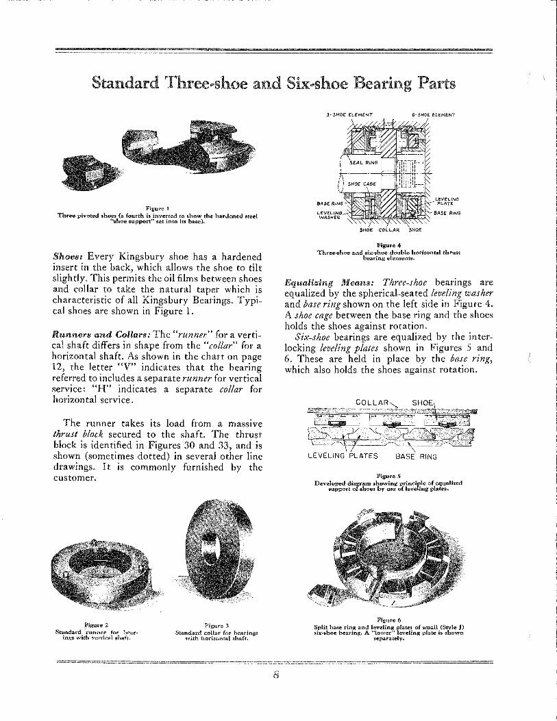
Shoes: Every Kingsbury shoe has a hardened insert in the back, which allows the shoe to tilt slightly. This permits the oil films between shoes and collar to take the natural taper which is characteristic of all Kingsbury Bearings. Typical shoes are shown in Figure 1.
Runners and Collars: The "runner" for a vertical shaft differs in shape from the "collar" for a horizontal shaft. As shown in the chart on page 12, the letter "V" indicates that the bearing referred to includes a separate runner for vertical service: "H" indicates a separate collar for horizontal service.
The runner takes its load from a massive thrust block secured to the shaft. The thrust block is identified in Figures 30 and 33, and is shown (sometimes dotted) in several other line drawings. It is commonly furnished by the customer.
Figure 2 Standard lrunner for bear
inga with verdcal 6haft.
-----------
Figure 3 Standard collar for bearings
with horizontal shaft.
8
SHOE COLLAR SHOE
Figure 4 Three-shoe and .i,,-.hoe double horizontal thrust
bearing elements.
Equalizing Means: Three-shoe bearings are equalized by the spherical-seated leveling washer and base ring shown on the left side in Figure 4. A shoe cage between the base ring and the shoes holds the shoes against rotation.
Six-shoe bearings are equalized by the interlocking leveling plates shown in Figures 5 and 6. These are held in place by the base ring, which also holds the shoes against rotation.
Figure 5 Developed diagram .howing principle of equalized
support of shoes by use of leveling plateth
Figure 6 Split base ring and leveling plate. of small (Style J) Six~8hoe bearing. A "lower" leveling plate is shown
separately~
Standard Assemblies: Three .. shoe and Six .. shoe
Figure 7 Three~8hoe bearing, Style N. For vertical or horizontal shaft.
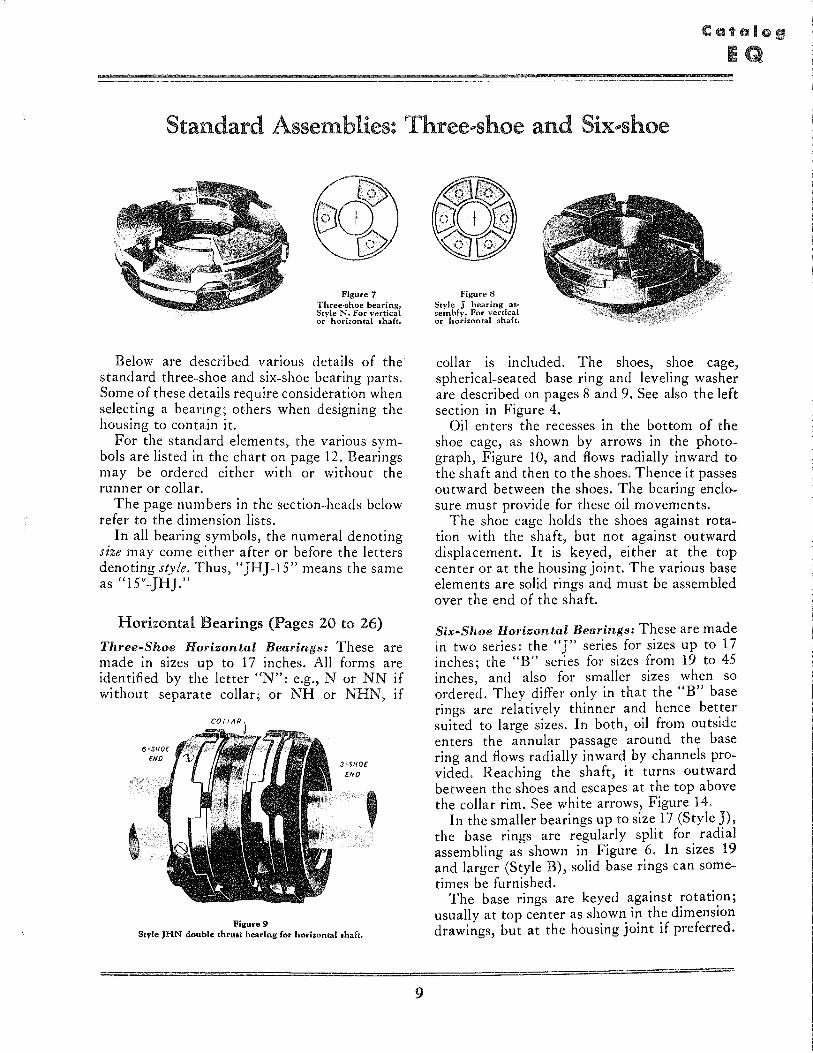
Below are described various details of the standard three-shoe and six-shoe bearing parts. Some of these details require consideration when selecting a bearing; others when designing the housing to con tain it.
For the standard elements, the various symbols are listed in the chart on page 12. Bearings may be ordered either with or without the runner or collar.
The page numbers in the section-heads below refer to the dimension lists.
In all bearing symbols, the numeral denoting size may come either after or before the letters denoting style. Thus, "JHJ-15" means the same as "15"-JHJ."
Horizontal Bearings (Pages 20 to 26)
Three-Shoe Horizontal Bearings: These are made in sizes up to 17 inches. All forms are identified by the letter "N": e.g., N or NN if without separate collar; or NH or NHN, if
Figure 9
3-SHOE
END , Style JHN double thrult bearing for horizontal aha ft.
9
Figure 8 Stvle J bearing as· sembly. For vertical or horizontal shaft.
collar is included. The shoes, shoe cage, spherical-seated base ring and leveling washer are described on pages 8 and 9. See also the left section in Figure 4.
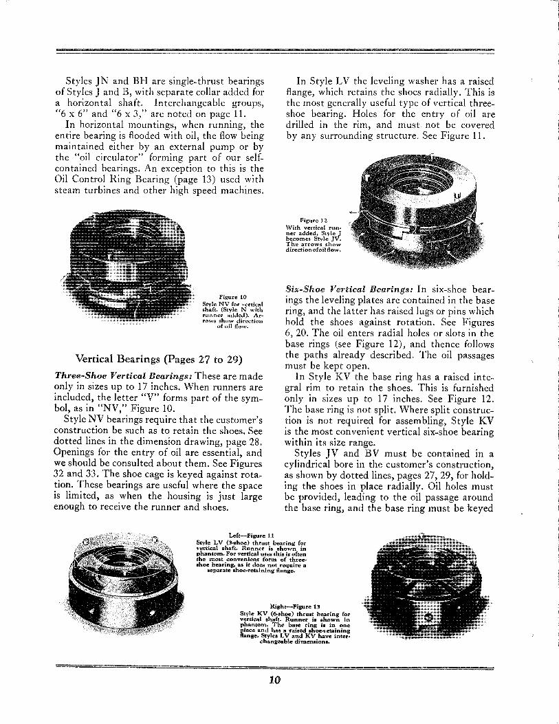
Oil enters the recesses in the bottom of the shoe cage, as shown by arrows in the photograph, Figure 10, and flows radially inward to the shaft and then to the shoes. Thence it passes outward between the shoes. The bearing enclosure must provide for these oil movements.
The shoe cage holds the shoes against rotation with the shaft, but not against outward displacement. It is keyed, either at the top center or at the housing joint. The various base elements are solid rings and must be assembled over the end of the shaft.
Six-Shoe Horizontal Bearings: These are made in two series: the "J" series for sizes up to 17 inches; the "B" series for sizes from 19 to 45 inches, and also for smaller sizes when so ordered. They differ only in that the "B" base rings are relatively thinner and hence better suited to large sizes. In both, oil from outside enters the annular passage around the base ring and flows radially inward by channels provided. Reaching the shaft, it turns outward between the shoes and escapes at the top above the collar rim. See white arrows, Figure 14.
In the smaller bearings up to size 17 (Style J), the base rings are regularly split for radial assembling as shown in Figure 6. In sizes 19 and larger (Style B), solid base rings can sometimes be furnished.
The base rings are keyed against rotation; usually at top center as shown in the dimension drawings, but at the housing joint if preferred.
;;;
Styles IN and BH are single-thrust bearings of Styles J and B, with separate collar added for a horizontal shaft. Interchangeable groups, "6 x 6" and "6 x 3," are noted on page li.
In horizontal mountings, when running, the entire bearing is flooded with oil, the flow being maintained either by an external pump or by the "oil circulator" forming part of our selfcontained bearings. An exception to this is the Oil Control Ring Bearing (page 13) used with steam turbines and other high speed machines.
Figure 10 Style NV for vertical shaft. (Style N with runner added). Arrows show direction
of oil flow.
Vertical Bearings (Pages 27 to 29)
Three-Shoe Vertical Bearings: These are made only in sizes up to 17 inches. When runners are included, the letter "V" forms part of the symbol, as in "NV," Figure 10.
Style NV bearings require that the customer's construction be such as to retain the shoes. See dotted lines in the dimension drawing, page 28. Openings for the entry of oil are essential, and we should be consulted about them. See Figures 32 and 33. The shoe cage is keyed against rotation. These bearings are useful where the space is limited, as when the housing is just large enough to receive the runner and shoes.
In Style LV the leveling washer has a raised flange, which retains the shoes radially. This is the most generally useful type of vertical threeshoe bearing. Holes for the entry of oil are drilled in the rim, and must not be covered by any surrounding structure. See Figure 11.
Figure 12 With vertical run .. ner added, Style J becomes Style JV. The arrows show direction ofoB flow",
Six-Shoe Vertical Bearings: In six-shoe bearings the leveling plates are contained in the base ring, and the latter has raised lugs or pins which hold the shoes against rotation. See Figures 6, 20. The oil enters radial holes or slots in the base rings (see Figure 12), and thence follows the paths already described. The oil passages must be kept open.
In Style KV the base ring has a raised integral rim to retain the shoes. This is furnished only in sizes up to 17 inches. See Figure 12. The base ring is not split. Where split construction is not required for assembling, Style KV is the most convenient vertical six-shoe bearing within its size range.
Styles JV and BV must be contained in a cylindrical bore in the customer's construction, as shown by dotted lines, pages 27,29, for holding the shoes in place radially. Oil holes must be provided, leading to the oil passage around the base ring, and the base ring must be keyed
Left-Figure 11 Style LV (3 .. hoe) thrust bearing for vertical shaft. Runner is shown in ph.antom. For vertical uses this is often the moat convenient form of three-shoe bearing, as it does not require a
separate ahoe .. retaining flange.
Right-Figure 13 Style KV (6-shoe) thrust bearing for vertical ahaft. Runner is shown in phantom. The base ring i. in one piece and hag a rai.ed ohoe.retaining flange. Styles LV and KV have inter.
changeable dimension ••
10
against rotation. Styles JV and BV are regularly split, but Style BV can sometimes be furnished solid.
Style JV is made in sizes up to 17 inches. From 19 inches upward Style BV replaces it. The two are similar except that, since the base ring in Style B is more shallow, the oil passages in it must be supplemented by matching oil slots in the customer's construction. See dotted lines marked Oil Slots, in the dimension drawings for Styles KBV and BV, page 29.
Style KBV is roughly equivalent to KV in sizes 19 inch and larger. It has a split shoeretaining band clamped around the upper part of the base ring; hence the base ring requires locating by dowels. The base ring is made in halves, with bolted joints.
Other Details
End Play: End play in horizon tal bearings is always fixed by filler pieces or shims at one or both ends of the bearing cavity behind the base rings or kveling washers. Since the working surfaces do not wear in normal service, the end play rarely needs to be taken up.
Bearings Without Collars: Without "runner or "collar," the three-shoe bearing is designated simply N, and the six-shoe bearing simply J or B. They are employed with integral thrust collars, and may be mounted either vertically or horizontally. Double bearings, for use with an integral collar, are designated Style NN, 11 or BB. In all cases our recommendations regarding oil passages, keying, and so on, must be carefully followed.
Interchangeability: In sizes 5 to 17, the sixshoe (but not Style B) and three-shoe groups of elements are interchangeable. Thus, Styles J and N are interchangeable; likewise JV and NV; 11 and NN; also JHJ, NHN and JHN.
Fits: There are no press or shrink fits on any dimensions listed. Collars on shafts, and keys in same, should be easy sliding fi ts, with the collar held square by the shaft shoulder and a large nut driven very tight. Thrust blocks must be a free fit in bore B of the vertical runner. Six-shoe and three-shoe base rings, and threeshoe leveling washers, are loose fits in the casing bore.
11
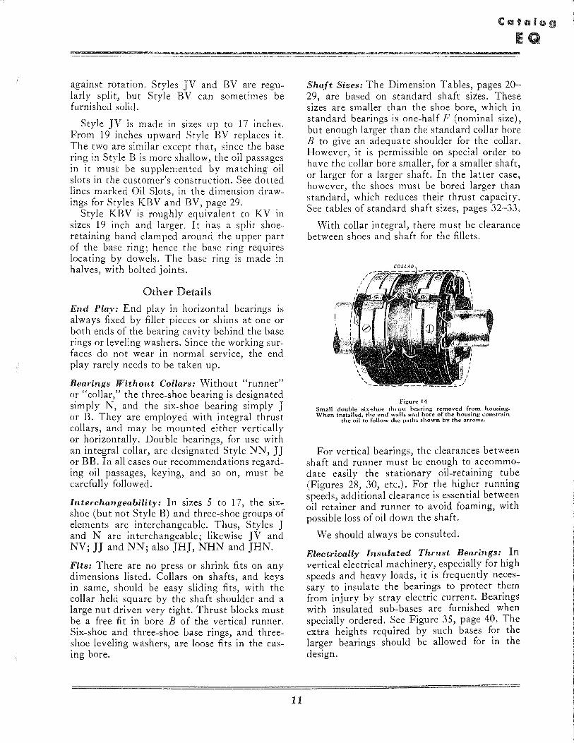
Shaft Sizes: The Dimension Tables, pages 20-29, are based on standard shaft sites. These sizes are smaller than the shoe bore, which in standard bearings is one-half F (nominal size), but enough larger than the standard collar bore B to give an adequate shoulder for the collar. However, it is permissible on special order to have the collar bore smaller, for a smaller shaft, or larger for a larger shaft. In the latter case, however, the shoes must be bored larger than standard, which reduces their thrust capacity. See tables of standard shaft sizes, pages 32-33.
With collar integral, there must be clearance between shoes and shaft for the fillets.
Figure 14 Small double six,shoe thrust bearing removed from housing. When installed, the end walls and bore of the housing constrain
the oil to follow the paths shown by the arrows.
For vertical bearings, the clearances between shaft and runner must be enough to accommodate easily the stationary oil-retaining tube (Figures 28, 30, etc.). For the higher running speeds, additional clearance is essential between oil retainer and runner to avoid foaming, with possible loss of oil down the shaft.
We should always be consulted.
Electrically Insulated Thrust Bearings: In vertical electrical machinery, especially for high speeds and heavy loads, it is frequently necessary to insulate the bearings to protect them from injury by stray electric current. Bearings with insulated sub-bases are furnished when specially ordered. See Figure 35, page 40. The extra heights required by such bases for the larger bearings should be allowed for in the design.
Bearing Symbol
(See Note)
JHJ
JH
JJ J
BHB BH BB B
NHN NH NN N
JHN IN
BHN BN
KV
JV
LV
NV
BV
KBV
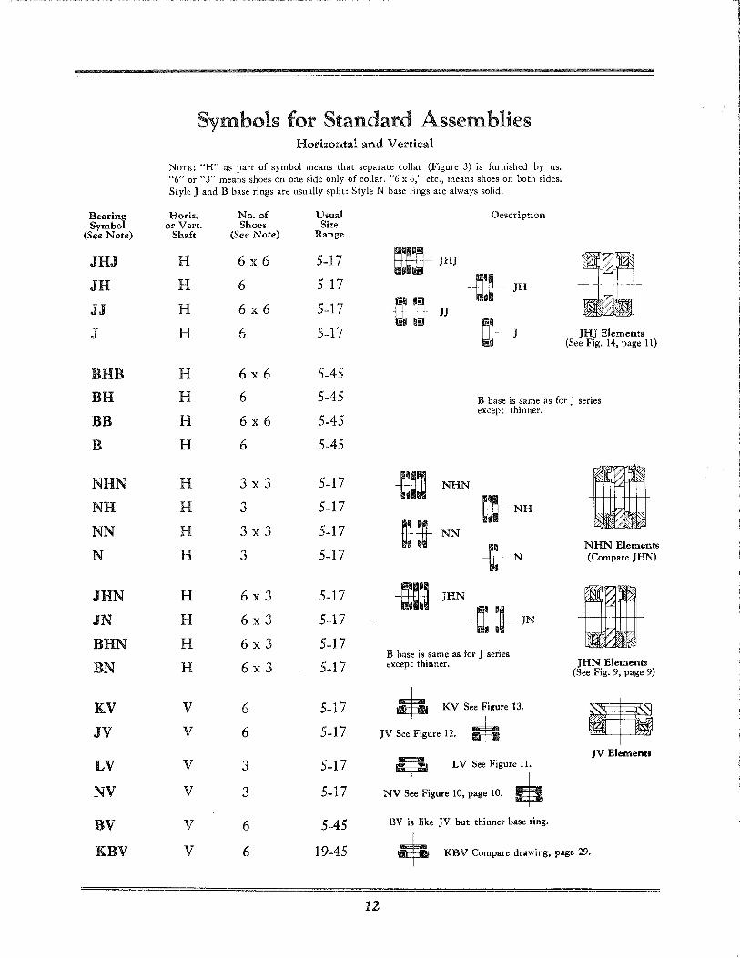
Symbols for Standard Assemblies Horizontal and Vertical
NOTE: "H" as part of symbol means that separate collar (Figure 3) is furnished by us. "6" or "3" means shoes on one side only of collar. "6 x 6," etc., means shoes on both sides. Style J and B base rings are usually split: Style N base rings are always solid.
Horiz. or Vert.
Shaft
H
H
H
H
No. of Shoes
(See Note)
6x6
6
6x6
6
Usual Size
Range
5-17
5-17
5-17
5-17
Description
1!fD- JHJ
JHJ Elements (See Fig. 14, page 11)
H
H
H
H
6x6
6
6x6
6
5-45 5-45
5-45
5-45
B base is same as for J series except thinner.
H
H
H
H
H
H
H
H
v V
V
V
V
V
3x3
3
3x3
3
6x3
6x3
6x3
6x3
6
6
3
3
6
6
5-17
5-17
5-17
5-17
5-17
5-17
5-17
5-17
5-17
5-17
5-17
5-17
5-45
19-45
12
.NHN
~~ NN -&:!- NH
-oc- N
-m~JHN~ t IN
B base is same as for J series except thinner.
• KV See Figure 13.
JV See Figure 12. •
• LV See Figure 11.
NV See Figure 10, page 10. •
BV is like JV but thinner base ring.
NHN Elements (Compare JHN)
JHN Elements (See Fig. 9, page 9)
JV Elements
+ KBV Compare drawing, page 29.
High Speed Bearings for Turbines and Blowers Horizontal and Vertical
I .
c.-------~
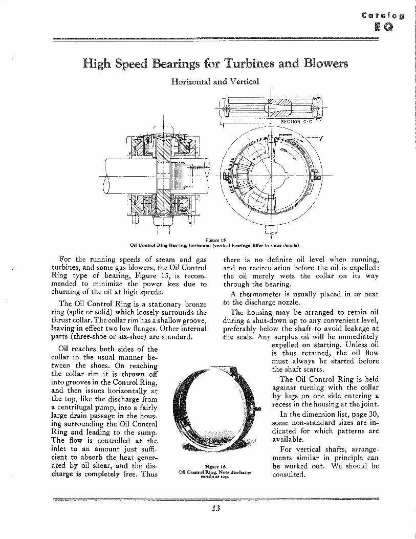
Figure 1S Oil Control Ring Bearing, horizontal (vertical bearing. differ in 80me detail.).
For the running speeds of steam and gas turbines, and some gas blowers, the Oil Control Ring type of bearing, Figure 15, is recommended to minimize the power loss due to churning of the oil at high speeds.
The Oil Control Ring is a stationary bronze ring (split or solid) which loosely surrounds the thrust collar. The collar rim has a shallow groove, leaving in effect two low flanges. Other internal parts (three-shoe or six-shoe) are standard.
Oil reaches both sides of the collar in the usual manner be-
there is no definite oil level when running, and no recirculation before the oil is expelled: the oil merely wets the collar on its way through the bearing.
A thermometer is usually placed in or next to the discharge nozzle.
The housing may be arranged to retain oil during a shut-down up to any convenient level, preferably below the shaft to avoid leakage at the seals. Any surplus oil will be immediately
expelled on starting. Unless oil is thus retained, the oil flow must always be started before the shaft starts.
The Oil Control Ring is held against turning with the collar by lugs on one side entering a recess in the housing at the joint.
In the dimension list, page 30, some non-standard sizes are indicated for which patterns are available.
tween the shoes. On reaching the collar rim it is thrown off into grooves in the Control Ring, and then issues horizontally at the top, like the discharge from a centrifugal pump, into a fairly large drain passage in the housing surrounding the Oil Control Ring and leading to the sump. The flow is controlled at the inlet to an amount just sufficient to absorb the heat generated by oil shear, and the discharge is completely free. Thus
Figure 16
For vertical shafts, arrangements similar in principle can be worked out. We should be consulted. Oil Control Ring. Note diocharge
n .... leat top.
13
Lubrication, Cooling and Housing Design
Although the Kingsbury principle involves continual self-renewal of the oil films between shoes and collar, the thickness of those films (and hence the safety of the bearing) depends on the operating conditions. These conditions include load per square inch of shoe area (which can be greater wi th large shoes than wi th small ones), and viscosity of the oil at running temperature. Temperature depends on speed and on the cooling means. At high speeds (turbines and blowers) there is also the possibility of power loss due to churning. This is minimized by using the Oil Control Ring, page 13.
Though the heating due to oil shear is small, it is a definite quantity which may be calculated. The cooling agent may be an attached external cooler. Or the bearing may be tied into a general lubricating system with central cooling. For low speeds, air radiation may be sufficient: see last paragraphs below. Wi th vertical bearings, there may be a copper coil in the oil bath, through which cooling water flows.
The "in ternal" resistance to flow of oil through the bearing assembly itself is slight. The piping and the oil passages in the bearing should be designed to carry the required flow easily. If the oil pump develops high pressure, it may be necessary to restrict the flow to avert needless loss of power. Three to five pounds per square inch at the inlet is usually sufficient.
With oil cooling, the flow must be sufficient to carry off the heat generated by oil shear between shoes and collar. The operating instructions usually specify the viscosity and oil flow recommended. When the correct pressure and restrictions have been established, it is best to have the restrictions take the form of suitable drilled plugs in the oil line at inlet or outlet or both, so that they cannot be inadvertently changed. (See, however, the reference to Oil Control Ring bearings, below.)
For large vertical bearings, a thermometer or temperature indicator is frequently installed, usually in the shoes of the loaded side.
Horizontal Bearings
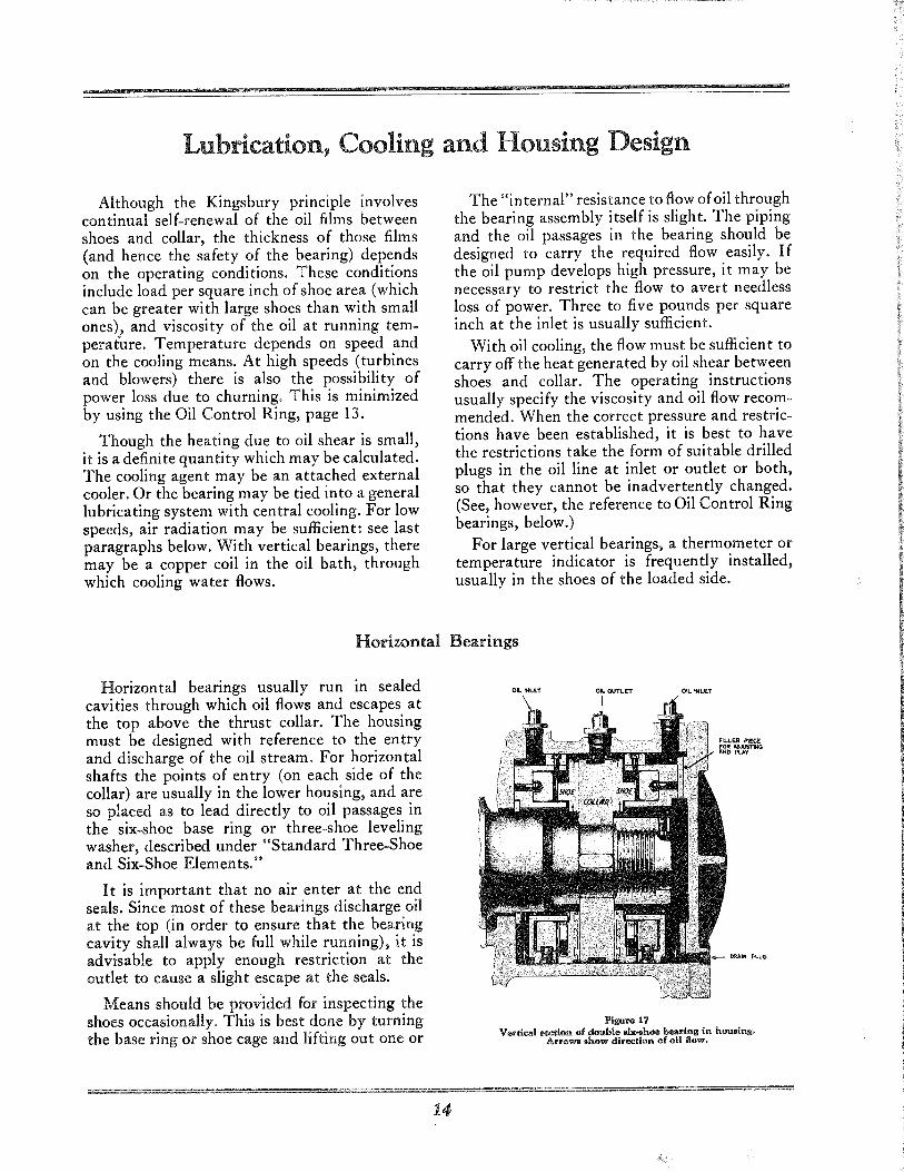
Horizontal bearings usually run in sealed cavities through which oil flows and escapes at the top above the thrust collar. The housing must be designed with reference to the entry and discharge of the oil stream. For horizontal shafts the points of entry (on each side of the collar) are usually in the lower housing, and are so placed as to lead directly to oil passages in the six-shoe base ring or three-shoe leveling washer, described under "Standard Three-Shoe and Six-Shoe Elemen ts."
It is important that no air enter at the end seals. Since most of these bearings discharge oil at the top (in order to ensure that the bearing cavity shall always be full while running), it is advisable to apply enough restriction at the outlet to cause a slight escape at the seals.
Means should be provided for inspecting the shoes occasionally. This is best done by turning the base ring or shoe cage and lifting out one or
14
OK.. INU.T OIL OUTLtT
Figure 17
FILLER PiI!.C.E FOR ,6.O.,IO&TlNG INO puy
Vertical oectlon of double .I" .. h"" bearing in hou.lnl!. Arrows .h" ... direction of 011 flow.
more shoes. For large bearings, an access cover is desirable for that purpose.
Sometimes the bearing cavity is so designed that no oil is retained when not running. Thus, there may be an oilleakoff at the bottom, aimed to prevent trapping sediment, or to minimize corrosion during a long shutdown. Or the oil may be introduced at such a point or in such a manner that it can drain back through the inlet
upon stopping. For such conditions, oil circulation must always be started before the shaft starts to turn.
When an Oil Control Ring is used, only the inlet is restricted, the outlet being left wholly free. The top discharge is then tangential, like that from a centrifugal pump, into a large drain passage. See "High Speed Bearings for Turbines and Blowers," page 13.
Vertical Bearings
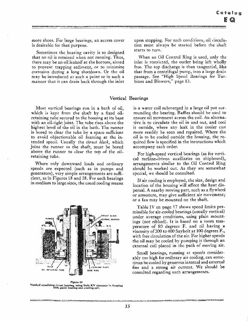
Most vertical bearings run in a bath of oil, which is kept from the shaft by a fixed oilretaining tube secured to the housing at its base with an oil-tight joint. The tube rises above the highest level of the oil in the bath. The runner is bored to clear the tube by a space sufficient to avoid objectionable oil foaming at the intended speed. Usually the thrust block, which joins the runner to the shaft, must be bored above the runner to clear the top of the oilretaining tube.
Where only downward loads and ordinary speeds are expected (such as in pumps and generators), very simple arrangements are sufficient, as in Figures 18 and 28. For such bearings in medium to large sizes, the usual cooling means
Figure 18 Veri/cal equalizing Ihm.! bearing. "olng Style KV elements in housing
with guide bearing and cooling coli.
15
is a water coil submerged in a large oil pot surrounding the bearing. Baffles should be used to ensure oil movement across the coil. An alternative is to circulate the oil in and out, and cool it outside, where any leak in the cooler can more readily be seen and repaired. Where the oil is to be cooled outside the housing, the required flow is specified in the instructions which accompany each order.
For high-speed vertical bearings (as for vertical turbine-driven auxiliaries on shipboard), arrangements similar to the Oil Control Ring should be worked out. As they are somewhat special, we should be consulted.
If air cooling is employed, the size, design and location of the housing will affect the heat dispersal. A nearby moving part, such as a flywheel or armature, may give sufficient air movement; or a fan may be mounted on the shaft.
Table IV on page 17 shows speed limits permissible for air-cooled bearings (usually vertical) under average conditions, using plain mount-ings (not ribbed). It is based on a room temperature of 80 degrees F. and oil having a viscosity of300 to 400 Saybolt at 100 degrees F., with free circulation of the air. For higher speeds the oil may be cooled by pumping it through an external coil placed in the path of moving air.
Small bearings, running at speeds considerably too high for ordinary air cooling, can sometimes be cooled by generous internal and external fins and a strong air current. We should be consulted regarding such arrangements.
=
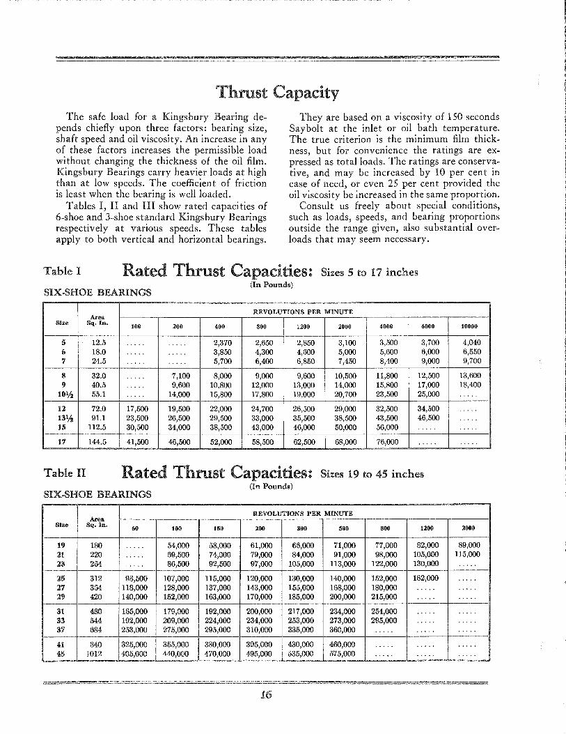
Thrust Capacity The safe load for a Kingsbury Bearing de
pends chiefly upon three factors: bearing size, shaft speed and oil viscosity. An increase in any of these factors increases the permissible load without changing the thickness of the oil film. Kingsbury Bearings carry heavier loads at high than at low speeds. The coefficient of friction is least when the bearing is well loaded.
Tables I, II and III show rated capacities of 6-shoe and 3-shoe standard Kingsbury Bearings respectively at various speeds. These tables apply to both vertical and horizontal bearings.
They are based on a viscosity of 150 seconds Saybolt at the inlet or oil bath temperature. The true criterion is the minimum film thickness, but for convenience the ratings are expressed as total loads. The ratings are conservative, and may be increased by 10 per cent in case of need, or even 25 per cen t provided the oil viscosi ty be increased in the same proportion.
Consult us freely about special conditions, such as loads, speeds, and bearing proportions outside the range given, also substantial overloads that may seem necessary.
Table I Rated Thrust Capacities: Sizes 5 to 17 inches
SIX.SHOE BEARINGS (In Pounds)
REVOLUTIONS PER MINUTE Area
Size Sq. In. 100 200 400 800 1200 2000 4000 6000 10000
5 12.5 ..... . .... 2,370 2,650 2,850 3,100 3,500 3,700 4,040 6 18.0 .... . ..... 3,850 4,300 4,600 5,000 5,600 6,000 6,550 7 24.5 ..... . .... 5,700 6,400 6,850 7,450 8,400 9,000 9,700
8 32.0 ..... 7,100 8,000 9,000 9,600 10,500 11,800 12,500 13,600 I) 40.5 ..... 9,600 10,800 12,000 13,000 14,000 15,800 17,000 18,400
101/2 55.1 .... . 14,000 15,800 17,800 19,000 20,700 23,500 25,000 . . . . . 12 72.0 17,500 19,500 22,000 24,700 26,500 29,000 32,500 34,500 ..... 13% 91.1 23,500 26,500 29,500 33,000 35,500 38,500 43,500 46,500 . , ...
15 1l2.5 30,500 34,000 38,500 43,000 46,000 50,000 56,000 .... . .....
17 144.5 41,500 46,500 52,000 58,500 62,500 68,000 76,000 .... . .....
Table n Rated Thrust Capacities: Sizes 19 to 45 inches (In Pounds)
SIX.SHOE BEARINGS
REVOLUTIONS PER MINUTE Area
Size Sq. In. 60 100 150 200 300 500 800 1200 2000
19 180 ..... 54,000 58,000 61,000 66,000 71,000 77,000 82,000 89,000 21 220 ..... 69,500 74,000 79,000 84,000 91,000 98,000 105,000 115,000 23 264 .... . 86,500 92,500 97,000 105,000 113,000 122,000 130,000 .....
25 312 98,500 107,000 115,000 120,000 130,000 140,000 152,000 162,000 ..... 27 364 118,000 128,000 137,000 143,000 155,000 168,000 180,000 .... . ..... 29 420 140,000 152,000 163,000 170,000 185,000 200,000 215,000 .... . .....
---31 480 165,000 179,000 192,000 200,000 217,000 234,000 254,000 .... . ..... 33 544 192,000 209,000 224,000 234,000 253,000 273,000 295,000 .... . ..... 37 684 253,000 275,000 295,000 310,000 335,000 360,000 .... . .... . .....
41 840 325,000 355,000 380,000 395,000 430,000 460,000 .... . .... . ..... 45 1012 405,000 440,000 470,000 495,000 535,000 575,000 .... . ..... . ....
16
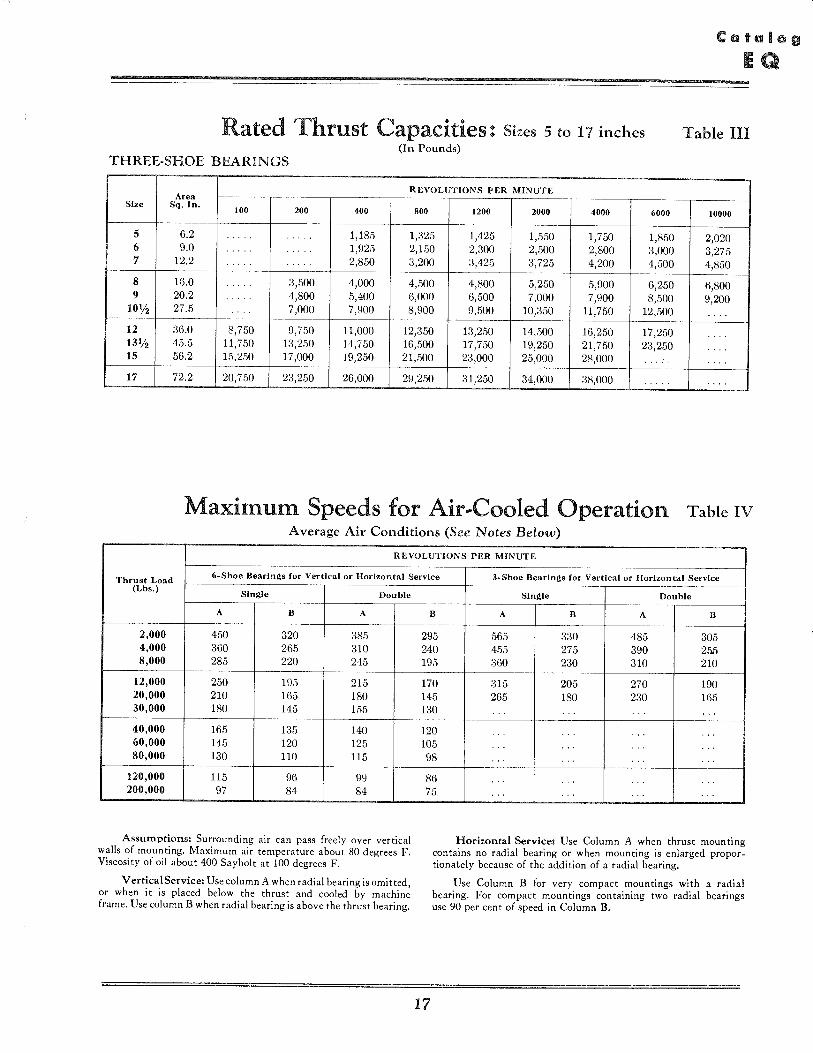
Rated Thrust Capacities: Sizes 5 to 17 inches Table HI (In Pounds)
THREE-SHOE BEARINGS
REVOLUTIONS PER MINUTE Area
Size Sq. In. 100 200 400 800 1200 2000 4000 6000 10000
5 6.2 .... . .. 1,185 1,325 1,425 1,550 1,750 1,850 2,020 6 9.0 . . . . . ... . . 1,925 2,150 2,300 2,500 2,800 3,000 3,275 7 12.2 . . . . . . ... 2,850 3,200 3,425 3,725 4,200 4,500 4,850
--
8 16.0 ... 3,500 4,000 4,500 4,800 5,250 5,900 6,250 6,800 9 20.2 ..... 4,800 .5,400 6,000 6,500 7,000 7,900 8,500 9,200
10% 27.5 .. ' . 7,000 7,900 8,900 9,500 10,350 11,750 12,500 . ...
12 36.0 8,750 9,750 11,000 12,350 13,250 14,500 16,2.50 17,250 .... 13% 45.5 11,750 1:3,250 14,750 16,500 17,750 19,250 21,750 23,250 .... 15 56.2 15,250 17,000 19,250 21,500 23,000 25,000 28,000 ... : . ...
17 72.2 20,750 23,250 26,000 29,2.50 31,250 34,000 38,000 . . ' .. . ...
Maximum Speeds for Air .. Cooled Operation Table IV Average Air Conditions (See Notes Below)
REVOLUTIONS PER MINUTE
Thrust Load 6- Shoe Bearln~s for Vertical or Horizon tal Service 3-Shoe Bearln~s for Vertical or Horizontal Service
(Lbs.) Sln~le Double
A B A
2,000 450 320 385 4,000 360 265 310 8,000 285 220 245
12,000 250 195 215 20,000 210 165 180 30,000 180 145 155
40,000 165 135 140 60,000 145 120 125 80,000 130 110 115
120,000 115 96 99 200,000 97 84 84
Assumptions: Surrounding air can pass freely over vertical walls of mounting. Maximum air temperature about 80 degrees F. Viscosity of oil about 400 Saybolt at 100 degrees F.
Vertical Service: Use column A when radial bearing is omitted, or when it is placed below· the thrust and cooled by machine frame. Use column B when radial bearing is above the thrust bearing.
Sln~le Double
B A B A B
295 565 330 485 305 240 455 275 390 25.5 195 360 230 310 210
170 315 205 270 190 145 265 180 230 165 130 .. . .. . .. . ., .
120 .. . .. . .. . ., . 105 .. . .. . .. . .' . 98 .. . .. . . .. ., . 86 .. . .. . . .. ., . 75 .. . .. . . .. ., .
Horizontal Service: Use Column A when thrust mounting contains no radial bearing or when mounting is enlarged proportionately because of the addition of a radial bearing.
17
Use Column B for very compact mountings with a radial bearing. For compact mountings containing two radial bearings use 90 per cent of speed in Column B.
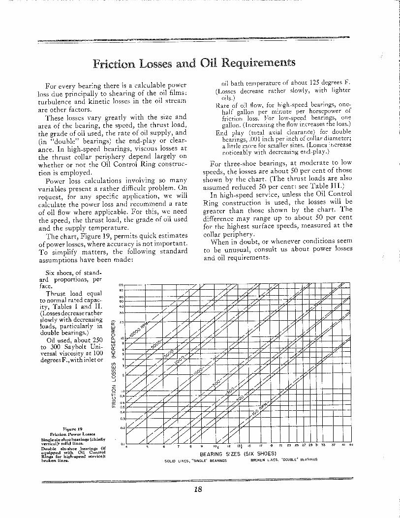
Friction Losses and Oil Requirements
For every bearing there is a calculable power loss due principally to shearing of the oil films: turbulence and kinetic losses in the oil stream are other factors.
These losses vary greatly with the size and area of the bearing, the speed, the thrust load, the grade of oil used, the rate of oil supply, and (in "double" bearings) the end-play or clearance. In high-speed bearings, viscous losses at the thrust collar periphery depend largely on whether or not the Oil Control Ring construction is employed.
Power loss calculations involving so many variables present a rather difficult problem. On request, for any specific application, we will calculate the power loss and recommend a rate of oil flow where applicable. For this, we need the speed, the thrust load, the grade of oil used and the supply temperature.
The chart, Figure 19, permits quick estimates of power losses, where accuracy is not importan t. To simplify matters, the following standard assumptions have been made:
Six shoes, of stand-ard proportions, per face.
Thrust load equal to normal rated capacity, Tables I and II. (Losses decrease ra ther slowly with decreasing loads, particularly in double bearings.)
Oil used, about 250 to 300 Saybolt Universal viscosity at 100 degrees F., wi th inlet or
100
so
60 50
40
'0
a:: 20
W ~ o a.. 10 w (j)
a:: 6
~ 5
z o 1.0 t5 0,8
cr: 0.6 LL 0,5
0.4
/ o~~V
,0°° ./ v
° V ':J0ov L
./ V .// ,v
/' ./
vZ / ./v
V/ /
vv ./ V
//
./ / /./ /
/~ V L L'
v/ 0°
~o/ 0/ /. 'l-o~ .'i
~ / ./
/
/' /
oil bath temperature of about 125 degrees F. (Losses decrease rather slowly, with lighter
oils.) Rate of oil flow, for high-speed bearings, one
half gallon per minute per horsepower of friction loss. For low-speed bearings, one gallon. (Increasing the flow increases the loss.)
End play (total axial clearance) for double bearings, .001 inch per inch of collar diameter; a little more for smaller sizes. (Losses increase noticeably with decreasing end-play.)
For three-shoe bearings, at moderate to low speeds, the losses are about 50 per cent of those shown by the chart. (The thrust loads are also assumed reduced 50 per cent: see Table III.)
In high-speed service, unless the Oil Control Ring construction is used, the losses will be greater than those shown by the chart. The difference may range up to about 50 per cent for the highest surface speeds, measured at the collar periphery.
When in doubt, or whenever conditions seem to be unusual, consult us about power losses and oil requirements.
/v /./ /~ ,'/ ,:, / / /. V // // i;?'
v "/ '/ /. vv ./; /./ v ..0 17'"
// /:/ .--: V '/ /./ 1/
/' v'?' .// V
~ V . .r; V ~/ V V ~
/ V V V f ~ V /L L' ~ V ~ / // '/ '/ '/ 'L .0
/ V IV/ /'/ 1;-- //" ~ V ./ / /v W
1// V/ /..: /' // /. /. ~ / /k/' ~ V
,i{/ // / .~ ;/' ~ /' ~
:/ ~/ f /' ~ / f'/
/':J0 /:;: l'/ 0/
V./ ~o./ / '/ ./ /. /'/ Q,0o/ Vv / / ~
V / ~L' /' / i//, /'~
Figure 19 // // /L .V; ./ V;/
0.3
0.2
Friction Power Losses Single six-shoe bearings (chiefly vertical): solid lines. Doubl!> six •• hoe bearing. (if equipped with Oil Control Rings for high·.peed .ervice): broken lines.
0, I
/ ~ /' 4
/'~ / :/ V /~
;/ ./
loi 12 13i 15 17 19 21 23 25 27 29 31 33 37 41 45
BEARING SIZES (SIX SHOES) SOLID LINES, "SINGLE" BEARINGS BROKEN LINES, "DOUBLE" BEARINGS
18
Choosing the Style and Size
The standard three- and six-shoe Thrust Bearings here listed are suitable for a great variety of uses, afloat and ashore and from small to large. Thus, a towboat with turbine or electric drive would be likely to use a 6 x 6 JHJ main thrust; a tanker, cargo ship or liner a 6 x 6 BHB; the two styles differing only in size and in relative thickness of the base rings. A medium-size hydroelectric generator or large vertical pump might use a six-shoe KBV, a smaller pump a JV or KV. Both would have shoes and base rings like the BHB and JHJ respectively, but a "runner" instead of a "collar."
For ordinary uses, therefore, once the load, speed, shaft size and shaft posi tion (horizon tal or vertical) are known, the normal choice can readily be made by referring to the Dimension and Capacity Tables. Other matters, such as space available, accessi bili ty and cooling arrangement, will still need to be considered. See page 41 for information which should accompany the inquiry or order for new applications. See pages 36 to 40 for examples of good mounting practice.
At steam and gas turbine speeds, avoidance of needless churning becomes important. For such cases, with horizontal shafts, the Oil Control Ring, page 13, is recommended. This calls for radically different treatment of oil flow. Figure 15 is typical, but details may be modi:; fied. For vertical shafts, similar but less standardized arrangements are available. We should always be consulted regarding new applications.
19
Selecting the Bearing
In choosing the thrust bearing for a given use, one starts with the shaft position (horizontal or vertical) and size. Six shoes carry maximum loads: three shoes carry half the load, but with smaller power loss. See the Tables of Dimensions and Capacity. Oil Control Rings are best for turbine speeds.
The size chosen must carry the load at the designed speed and with oil of appropriate viscosity. For ordinary commercial speeds (not turbine speeds) a safe preliminary assumption is that the oil should have a viscosity of 150 Saybolt seconds at the actual inlet or oil bath temperature. For heavy loads and slower speed, the viscosity may be higher.
For light loads, the smallest available bearing is likely to be determined by the shaft size, as the shoes must always clear the shaft by a substantial margin. Sometimes the shoes can be bored slightly oversize. A light oil is indicated.
For very light loads where the shaft dictates the bearing size, two-shoe equalizing bearings can be furnished. They are not, however, standard.
Where it is feasible to do so, we recommend the same oil as used elsewhere in the machine.
The chart on page 18 shows the friction loss for various loads and speeds, also oil flow where applicable. For special conditions, particularly high speed, we should always be consulted.
Air cooling is permissible with low speeds. The speeds shown in Table IV may be somewhat increased by use of internal and external fins. However, we should be consulted in all such cases, since cooling requirements rise rapidly with speed.
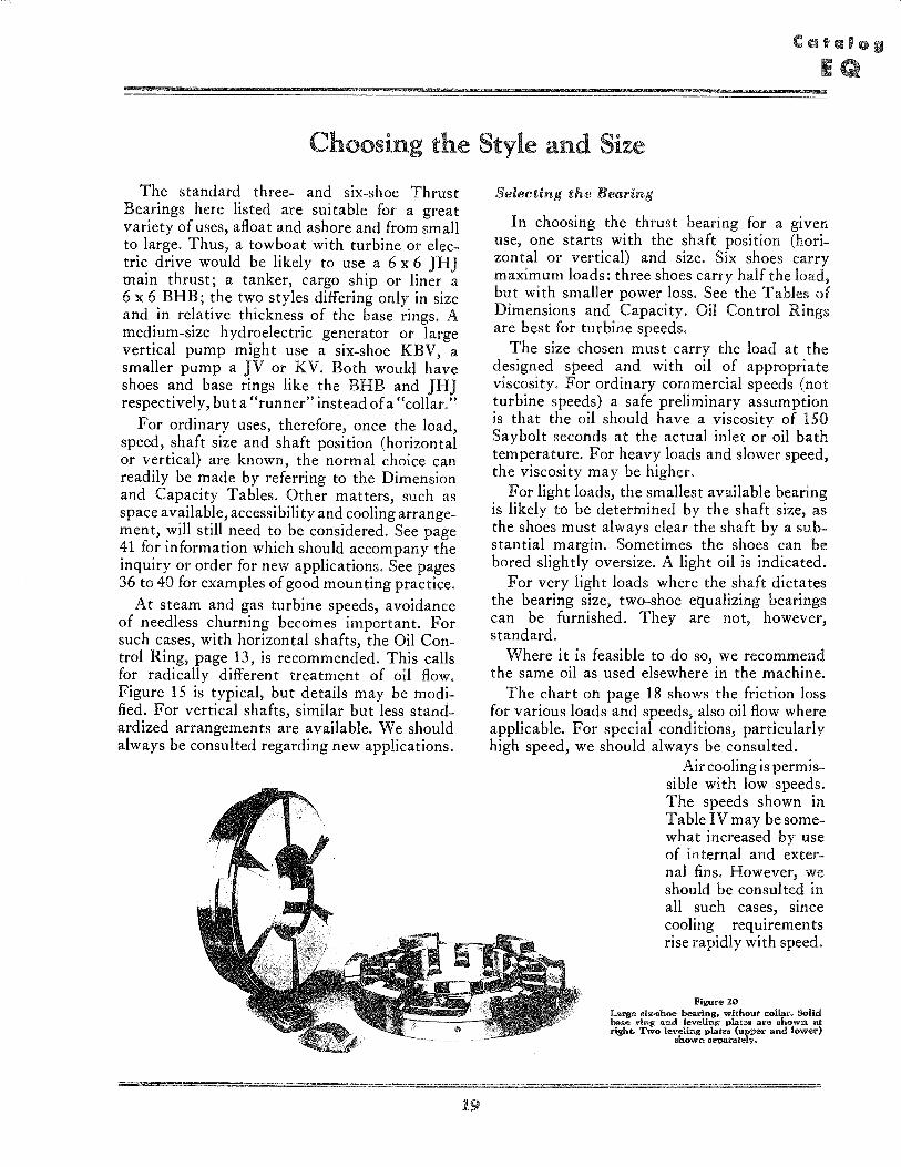
Figure 20 La'lli" .", .. hoe bearing, without collar. Solid baa .. ring and leveling piat"" are .how", .. t right. Two leveling plat"" (upper and lower)
m'hown separate1vo
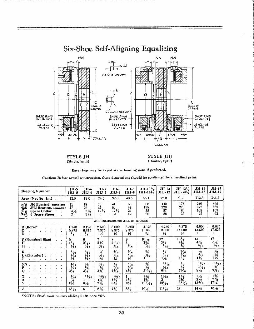
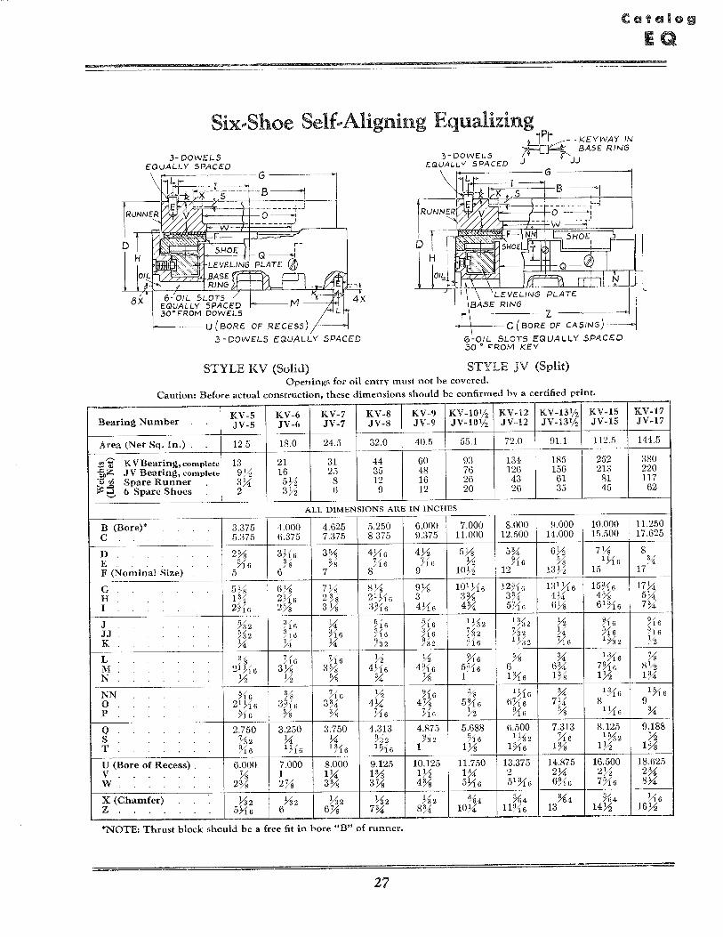
Six .. Shoe Self .. Aligning Equalizing
Z
BASE RING IN HALVES
LEVELING PI-ATE
STYLE JH (Single, Split)
.jf=, r.J.J
BASE: RING KEY
~K COLLAR KEYWA
BASE: RJNG IN HALVES
LE:VE:L1NG PLATE
Z
COLLAR
STYLE JHJ (Double, Split)
Base rings may be keyed at the housing joint if preferred.
C BORE OF CASING
BASE: RING IN HALVES
LEVE:LlNG PLATE
Caution: Before actual construction, these dimensions should be confirmed by a certified print.
Bearing Number JH-5 JH-6 JH-7 JH-8 JH-9 JH-I0ljz JH-12 JH.13% JH-15 JH-17 JHJ-5 JHJ-6 JHJ-7 JHJ-8 JHJ-9 JHJ-I0ljz JHJ-12 JHJ-13% JHJ-15 JHJ-17
Area (Net Sq. In.) 12.5 18.0 24.5 32.0 40.5 55.1 72.0 91.1 112.5 144.5
:3-=- JH Bearing, complete 11 18 30 41 56 88 140 175 240 366 fe~ JHJ Bearing, complete 17 29 47 64 88 138 223 270 372 569 'ii,B Spare Collar . . 472 772 1272 1772 24 38 57 80 108 163 ~...:I 6 Spare Shoes . 2 372 6 9 12 20 26 35 45 62
'-'
ALL DIMENSIONS ARE IN INCHES
B (Bore)* 1.750 2.125 2.500 3.000 3.500 4.125 4.750 5.375 6.000 6.625 C 5.375 6.375 7.375 8.375 9.375 11.000 12.500 14.000 15.500 17.625 E % % 72 % % % % :u 1 1
F (Nominal Size) 5 6 7 8 9 1072 12 13Y2 15 17 H 1% 2716 2% 21 716 3 3% 3% 4U 4% 5U JJ %2 %6 %6 %6 %6 %2 %2 U ~6 ~6
K %6 %6 U ~6 ~6 % % Y16 72 72 L (Chamfer) 716 716 716 716 716 %2 %2 %2 %2 ~ N 72 ~6 % % :u 1 1~ lU 1% 172
NN . ~6 % Y16 72 ~6 % 1716 % 1%6 1~6 P %6 % % Y16 Y16 72 ~6 % 1716 % Q 2% 3U 3% 4%6 4:U 51 716 672 7%6 8~ 9%6
T ~6 1716 1%6 1%6 1 1~ 1%6 1% 172 1% X % 1 lU 1% 172 1% 2 2U 272 2:U Y 5~ 6~ 7~ 8~ 9~ 101 716 12%6 131716 15%6 17U
Z 5716 6 6:U 7% 8% IOU 11~6 13 1472 1672
*NOTE: Shaft must be easy sliding fit in bore "B".
20
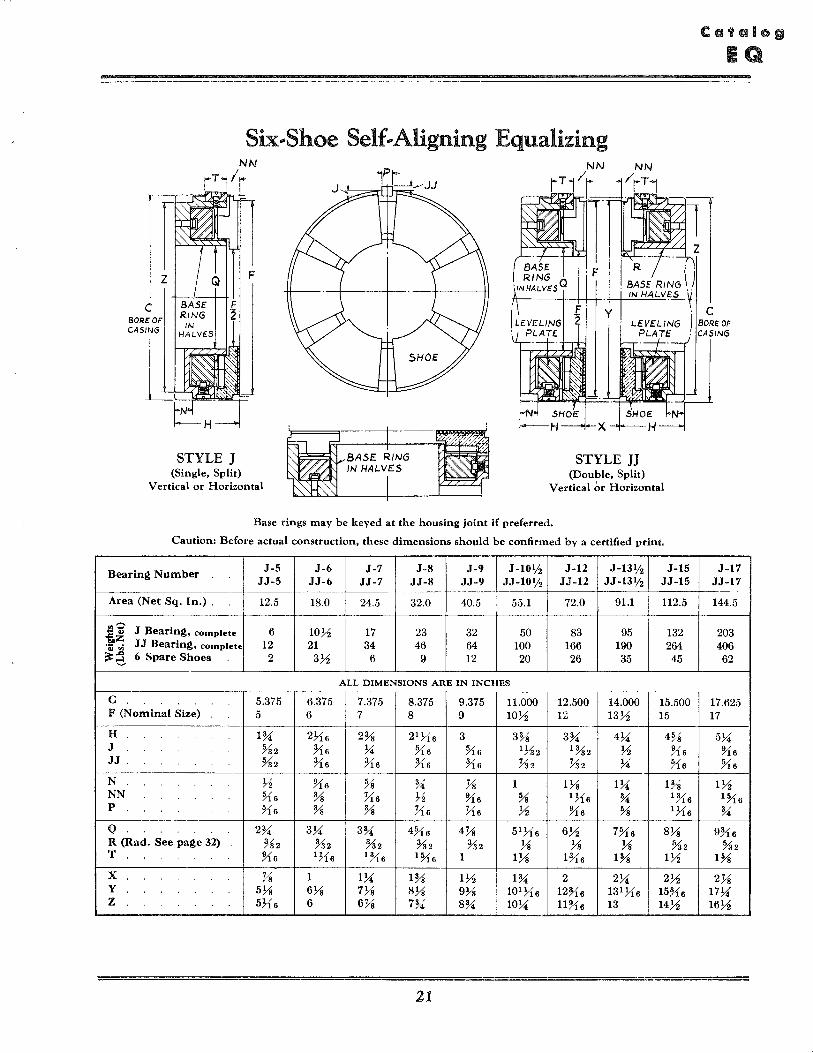
Six .. Shoe Self .. Aligning Equalizing
STYLE J (Single, Split)
Vertical or Horizontal
STYLE JJ (Double, Split)
Vertical ~r Horizontal
Base rings may be keyed at the housing joint if preferred.
Caution: Before actual construction, these dimensions should be confirmed by a certified print.
Bearing Number J-5 J-6 J-7 J-8 J-9 J -10% J-12 J-13% J-15 JJ-5 JJ-6 JJ-7 JJ-8 JJ-9 JJ -HI% JJ-12 JJ-13% JJ-15
Area (Net Sq. In.) . 12.5 18.0 24.5 32.0 40.5 55.1 72.0 91.1 112.5
"'? J Bearing, complete 6 1031 17 23 32 50 83 95 132 ... .., ij,z JJ Bearing, complete 12 21 34 46 64 100 166 190 264 "Q.i fIi ~~ 6 Spare Shoes 2 331 6 9 12 20 26 35 45
'-'
ALL DIMENSIONS ARE IN INCHES
C 5.375 6.375 7.375 8.375 9.375 11.000 12.500 14.000 15.500 F (Nominal Size) 5 6 7 8 9 1031 12 1331 15
~~ '0·
H 1~ 2716 2% 21 716 3 3% 3~ , 4>i 4% J %2 %6 >i Yi6 Yi6 lYs2 1%2 H %6 JJ %2 %6 %6 %6 %6 Y32 Y32 1 <' 74 ~6
N 31 J1G % ~ Ys 1 lYs l>i 1% NN Yi6 % Yi6 31 %6 % 1716 ~ 1%6 P Yi6 % % Yi6 Yi6 31 %6 % 1716
Q 2~ 3>i 3~ 4Yi6 4Ys 51 716 631 7Yi6 8Ys R (Rad. See page 32) %2 %2 %2 %2 %2 Ys Ys Ys %2 T Yi6 1716 1%6 lYi 6 1 lYs H16 1% 131
X Ys 1 l>i 1% 131 l~ 2 2>i 231 Y 5Ys 6Ys 7Ys 8Ys 9Ys 101 716 12%6 131 716 15%6 Z 5716 6 6Ys 7~ 8~ 10>i 11%6 13 1431
21
J-17 JJ-17 --144.5
203 406 62
17.625 17
5>i %6 Yi6
131 lYi6 ~
9%6 %2
1%
2Ys 17>i 1631
GI
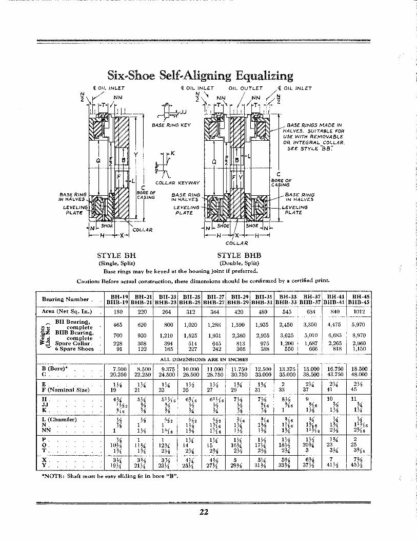
Six .. Shoe Self .. Aligning Equalizing
J,kJJ BASE RING KEY
y
COLLAR KEYWAY C
BASE RINGS MADE: IN HALVES. SUITABLE FOR USE WITH REMOVABLE OR INTEGRAL COLLAR.
SEE STYLE: 'B8:'
C BORE OF CASING
BASE RING ~-kd!~~~ IN HALVES
BORE: OF
if BASE RING -b-,;¢~jf' IN HALVES
BASE RING IN HALVES
LEVELING PL.ATE:
COLLAR
STYLE BH (Single, Split)
LEVELING PLATE
1"!:'IlH--J...LEVELING
COLLAR
STYLE BHB (Double, Split)
PLATE.
Base rings may be keyed at the housing joint if preferred.
Caution: Before actual construction, these dimensions should be confirmed by a certified print.
Bearin~ Number. BH-19 BH-21 BH-23 BH-25 BH-27 BH-29 BH-31 BH-33 BH-37 BH-41 BHB-19 BHB-21 BHB-23 BHB-25 BHB-27 BHB-29 BHB-31 BHB-33 BHB-37 BHB-41
Area (Net Sq. In.) 180 220 264 312 364 420 480 545 634 840
""' BH Bearin~, 465 620 800 1,020 1,288 1,590 1,935 2,450 3,350 4,475
ll- complete ..cO> BHB Bearin~, bIlZ 700 930 1,210 1,525 1,931 2,360 2,905 3,625 5,010 6,685 °41 tIS complete ~~ Spare Collar. 228 308 394 514 645 813 975 1,200 1,687 2,265
'-' 6 Spare Shoes 91 122 165 227 242 305 388 550 666 818
ALL DIMENSIONS ARE IN INCHES
B (Bore)* 7.500 8.500 9.375 10.000 11.000 11.750 12.500 13.375 15.000 16.750 C. 20.250 22.250 24.500 26.500 28.750 30.750 33.000 35.000 38.500 43.750
E. lYs 1;.i 1}4 1Yz lYz 1~ 1~ 2 2;.i 2;.i F (No'mi~al' Si~e) 19 21 23 25 27 29 31 33 37 41
H. 4~ 5;.i 51 YJ G 6~16 61 ~16 7% 7% 8% 9 10 JJ 1 ~~2 % % Yz Yz Yz ~16 %6 %6 % K. %6 % % ~ ~ % % 1 1% 1%
L (Chamfer) % Ys %2 %2 %2 ~16 H6 H6 ;.i ;.i N. % 1 1 1% 016 1;.i 1% 1:.16 1%6 1~ NN 1 1% 1?16 1% 1:.16 lYz 1% 1~ 11%6 2%
P. % 1 1 1;.i 1;.i 1;.i 1Yz lYz 1Yz 1~ Q. 10% 11~ 12~ 14 15 16;.i 17;.i 18Yz 20~ 23 T. 1~ 1~ 2% 2;.i 2% 2Yz 2% 2~ 3 3;.i
X. 3;.i 3% 3% 4;.i 4% 5 5;.i 5% 6% 7 Y. 19;.i 21;.i 23;.i 25;.i 27;.i 29% 31% 33% 37Yz 41Yz
*NOTE: Shaft must be easy sliding fit in bore "B".
22
BH-45 BHB-45
1012
5,970
8,970 2,960 1,150
18.500 48.000
2Yz 45
11 ~
1;.i
;.i 11%6 2%6
2 25
3%6
7% 45Yz
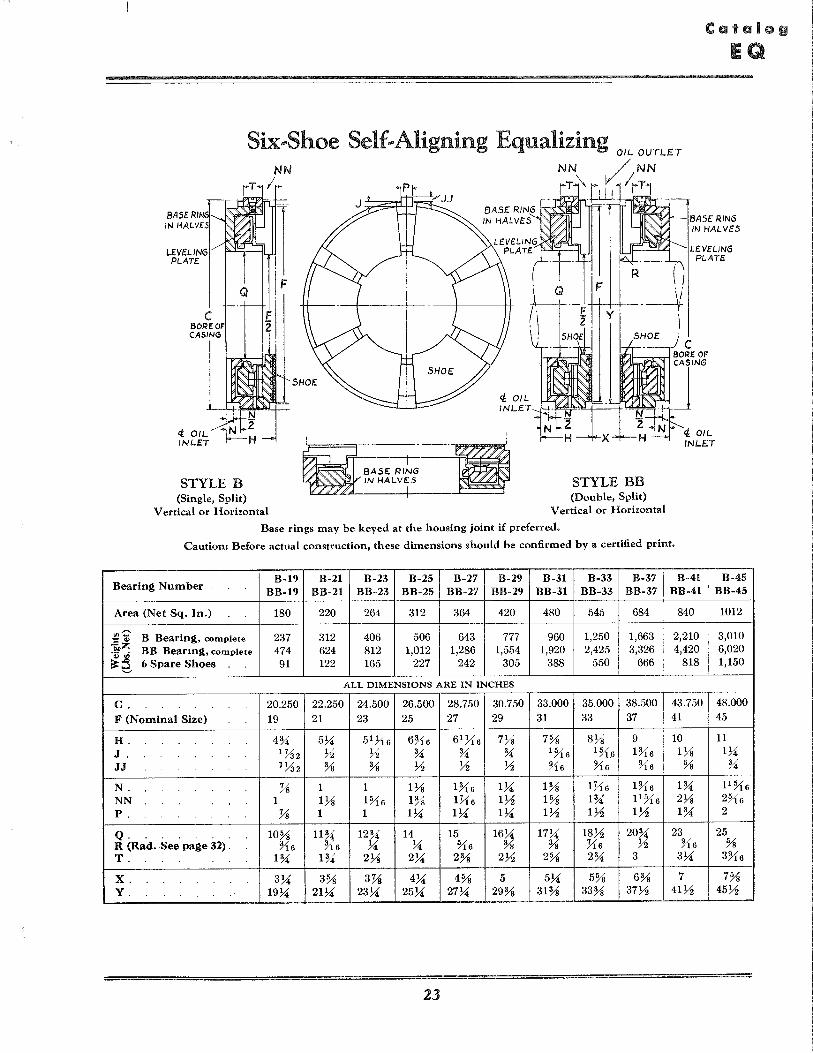
Six .. Shoe Self .. Aligning Equalizing OIL OUTLET
LEVELING PLATE:
C BORE OF CASING
<i OIL. INL.ET
Q
STYLE B (Single, Split)
Vertical or Horizontal
NN / NN
rT:\rJ( liT1
1 .
STYLE BB (Double, Split)
Vertical or Horizontal
\
BASE RING IN HALVES
LEVELING PLATE
Base rings may be keyed at the housing joint if preferred.
Caution: Before actual construction, these dimensions should be confirmed by a certified print.
Bearing Number B-19 B-21 B-23 B-25 B-27 B-29 B-31 B-33 B-37 B-41 B-45
BB-19 BB-21 BB-23 BB-25 BB-27 BB-29 BB-31 BB-33 BB-37 BB-41 BB-45
Area (Net Sq. In.) 180 220 264 312 364 420 480 545 684 840 1012
.,-:;-B Bearing, complete 237 312 406 506 643 777 960 1,250 1,663 2,210 3,010 -.,
f"z BB Bearing, complete 474 624 812 1,012 1,286 1,554 1,920 2,425 3,326 4,420 6,020 .~ uS
~~ 6 Spare Shoes 91 122 165 227 242 305 388 550 666 818 1,150
ALL DIMENSIONS ARE IN INCHES
C. 20.250 22.250 24.500 26.500 28.750 30.750 33.000 35.000 38.500 43.750 48.000 F (Nominal Size) 19 21 23 25 27 29 31 33 37 41 45
H. 4% 57.1 517{6 6~i6 61 7{6 7Ys 7% 8Ys 9 10 11 J. 1 %2 Yz Yz % % % 1YI6 1YI.6 His lYs 17.1 JJ 1732 % % Yz Yz Yz ~is YI6 YI6 % %
N. Ys 1 1 lYs lYi6 17.1 1% lYl6 lYIs 1% IlYI6 NN 1 lYs His 1% lYl6 lYz 1% 1% 1l~i6 2Ys 2YI6 P. Ys 1 1 17.1 17.1 17.1 lYz lYz lYz 1% 2
Q. 10% 11% 12% 14 15 167.1 177.1 18Yz 20% 23 25 R (Rad.See page 32) . Yi6 Yi6 7.1 7.1 YI6 % % Yl6 Yz YIs % T. 1% 1% 2Ys 274' 2% 2Yz 2% 2% 3 37.1 3YI6 x. 37.1 3% 3Ys 474' 4% 5 57.1 5% 6% 7 7% Y. 1974' 217.1 237.1 257.1 2774' 29% 31% 33% 37Yz 41Yz 45Yz
23
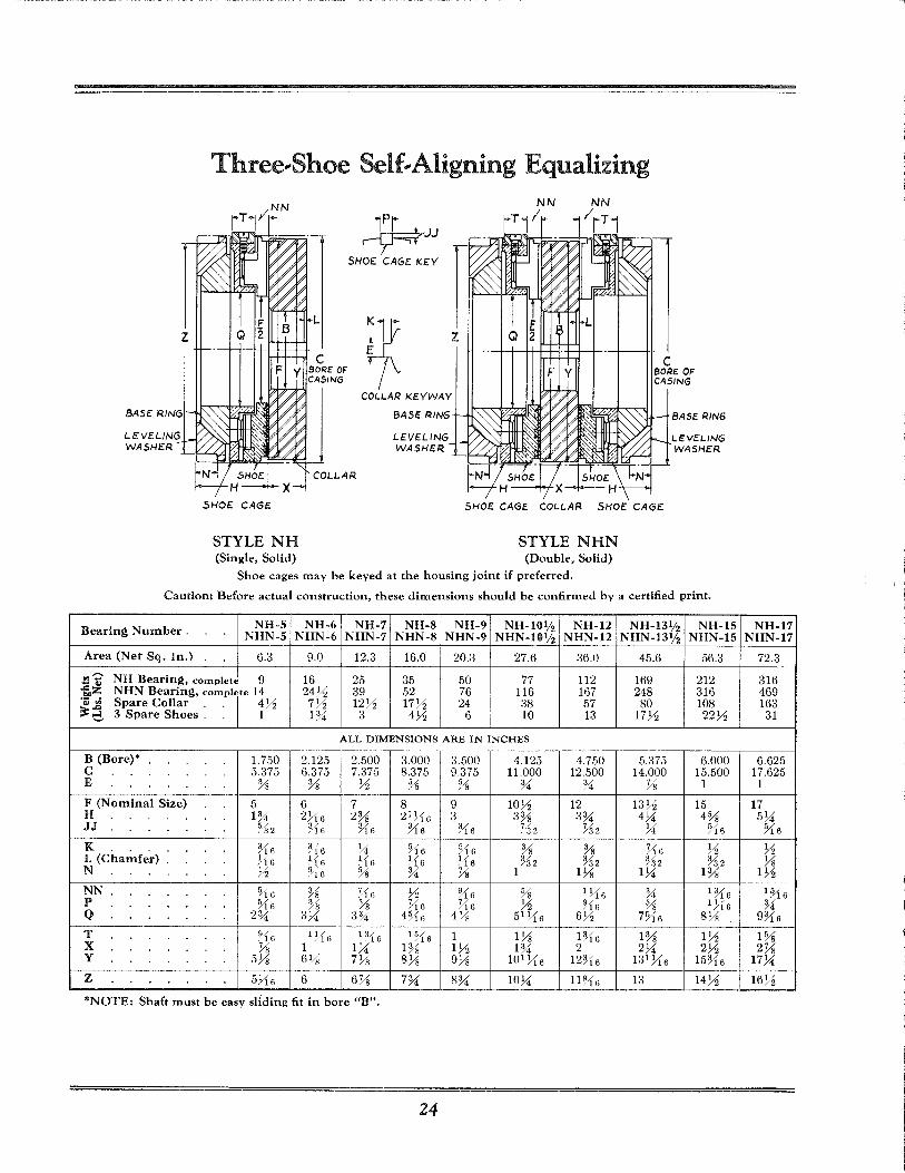
Three .. Shoe Self .. Aligning Equalizing
z
BASE RING
LEVELING WASHER
SHOE:. CAGE
STYLE NH (Single, Solid)
~ ...,:rJJ SHOE CAGE KEY
C BORE OF CASING
BASE RING BASE RING
LEVELING LEVELING WASHE.R WASHER
SHOE:. CAGE COLLAR SHOE CAGE
STYLE NHN (Double, Solid)
Shoe cages may be keyed at the housing joint if preferred.
Caution: Before actual construction, these dimensions should be confirmed by a certified print.
Bearin~ Number. NH-5 NH-6 NH-7 NH-8 NH-9 NH-IOljz NH-12 NH-13ljz NH-15 NHN-5 NHN-6 NHN-7 NHN-8 NHN-9 NHN-I0ljz NHN-12 NHN-13ljz NHN-15
Area (Net Sq. In,) 6.3 9.0 12.3 16.0 20.3 27.6 36.0 45.6 56.3 ,....
NH Bearin~, complete 9 16 25 35 50 77 112 169 212 .,--., f.,z NHN Bearin~, comPlre 14 24Yz 39 52 76 116 167 248 316 "Q) ul Spare Collar .. 4Yz 7Yz 12Yz 17Yz 24 38 57 80 108 ~~ 3 Spare Shoes.. 1 I%' 3 4Yz 6 10 13 17Yz 22Yz
ALL DIMENSIONS ARE IN INCHES
B (Bore)* 1.750 2.125 2.500 3.000 3.500 4.125 4.750 5.375 6.000 C 5.375 6.375 7.375 8.375 9.375 11.000 12.500 14.000 15.500 E % % Yz % % %' %' % 1
F (Nominal Size) 5 6 7 8 9 lOYz 12 13Yz 15 H I%, 2>16 2% 21j,16 3 3% 3%, 4),4 4% JJ %2 ?16 YJ6 ~16 ?16 7~2 %2 ),4 Yi6
K ~16 ~16 ),4 ~f6 5/ % % ~16 Yz /16 L (Chamfer) »6 !'16 >16 »6 >16 %2 %2 %2 %2 N Yz ~"16 % %' % 1 1% 1),4 1%
NN ?i6 % 5)6 Yz ~16 % 1 >16 %' lYJ 6 P ~16 ~~ % ~16 ;16 Yz ~16 % 1>16 Q 2% 3),4 3%, 4%6 4% 51>16 6Yz 7~16 8%
T ~16 1 >16 13'16 1 ~16 1 Hi H 16 1% 1Yz X % 1 1),4 1% 1Yz I%' 2 2),4 2Yz Y 5% 6~/g 7% 8% 9% 101 >16 12~16 13 1 >16 15YJ6
Z 5>16 6 6% 7%' 8%, 10),4 11 !J16 13 14Yz
*NOTE: Shaft must be easy sliding fit in bore "B".
24
NH-17 NHN-17
72.3
316 469 163
31
6.625 17.625
1
17 5;li
Yi6
Yz %
lYz
lYi6 %'
9YJ6
1% 2%
17;li
16Yz
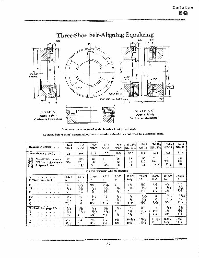
Three .. Shoe Self .. Aligning Equalizing
C eOREO CASING
z F
STYLE N (Single, Solid)
Vertical or Horizontal
NN
IrT1
STYLE NN (Double, Solid)
Vertical or Horizontal
Shoe cages may be keyed at the housing joint if preferred.
Caution: Before actual construction, these dimensions should be confirmed by a certified print.
Bearin~ Number N-5 N-6 N-7 N-S N-9 N-I0ljz N-12 N-13Yz N-15 NN-5 NN-6 NN-'1 NN-S NN-9 NN-I0Yz NN-12 NN-13ljz NN-15
Area (Net Sq. In.) . 6.3 9.0 12.3 16.0 20.3 27.6 36.0 45.6 56.3 .,c
N Bearin~, complete 4% 8Y:; 13 17 26 39 55 79 104 -.. f.,z NN Bearing, complete 9Y:; 17 26 34 52 78 110 158 208 .:V til
~~ 3 Spare Shoes 1 1% 3 4Y:; 6 10 13 17Y:; 22Y:;
ALL DIMENSIONS ARE IN INCHES
C 5.375 6.375 7.375 8.375 9.375 11.000 12.500 14.000 15.500 F (Nominal Size) 5 6 7 8 9 lOY:; 12 l3Y:; 15
H 1% 2716 2% 21 716 3 3% 3% 4U 4% JJ . %2 Yi6 ~{6 Yi6 ~{6 %2 %2 U ~6 N Y:; Us % % Ys 1 1% lU 1%
NN ~{6 % ~{6 Y:; U6 % 1716 % lYi6 P ~16 % % X6 X6 Y:; Us % 1716 Q 2% 3U 3% 4:M:s 4Ys 51716 6Y:; 7:M:6 8%
R (Rad. See page 32) %2 %2 %2 .%2 %2 % % % %2 T U6 1716 lYi6 1~6 1 1% lYio 1% lY:; X Ys 1 lU 1% lY:; 1% 2 2U 2Y:;
Y 5% 6% 7% 8% 9% 101 710 12Yi6 131>10 15Yi6 Z 5716 6 6Ys 7% 8% 1O~ nus 13 BY:;
25
N-I'1 NN-17
72.3
153 306 31
17.625 17
5U ~6
lY2 1~6
% 9%6
%2 1% 2Ys 17~ 16~
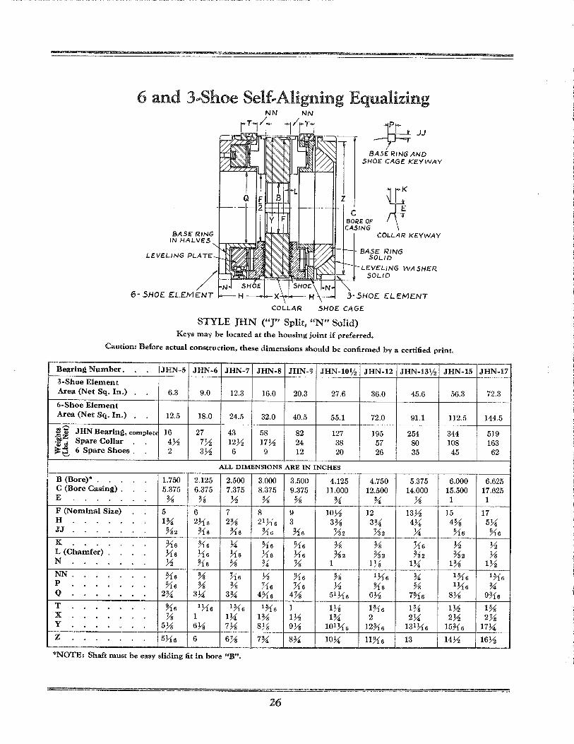
6 and 3 .. Shoe Self .. Aligning Equalizing
BASE R.ING IN HAL.VES
LEVELING PL.ATE
COL.L.AR
z
~JJ BASE RING AND
SHOE CAGE' KEYWAY
C SORE OF CASING
COLL.AR KEYWAY
BASE RING sou D
L.EVEL.iNG WASHER SOUD
3-5HO£ E:LEMENT
SHOE CAGE
STYLE JHN ("J" Split, "N" Solid) Keys may be located at the housing joint if preferred.
Caution: Before actual construction, these dimensions should be confirmed by a certified print.
Bearing Number. JHN-5 JHN-6 JHN-7 JHN-8 JHN-9 JHN-I01/2 JHN-12 JHN-13% JHN-15
3-Shoe Element Area (Net Sq. In.) 6.3 9.0 12.3 16.0 20.3 27.6 36.0 45.6 56.3
6-Shoe Element Area (Net Sq. In.) 12.5 18.0 24.5 32.0 40.5 55.1 72.0 91.1 112.5
:1'0 JHN Bearing, complet. 16 27 43 58 82 127 195 254 344 f.~ -43 wj Spare Collar 4Y2 7Y2 12Y2 17Y2 24 38 57 80 108 ~~ 6 Spare Shoes . 2 3Y2 6 9 12 20 26 35 45
ALL DIMENSIONS ARE IN INCHES
B (Bore)* 1.750 2.125 2.500 3.000 3.500 4.125 4.750 5.375 6.000 C (Bore Casing) . 5.375 6.375 7.375 8.375 9.375 11.000 12.500 14.000 15.500 E % % Y2 % % % % Ys 1
F (Nominal Size) 5 6 7 8 9 1OY2 12 13Y2 15 H 1% 2716 2% 21 716 3 3% 3% 4U 4% JJ %2 ~{6 Yl6 Yl6 Yl6 %2 %2 U ~6
K. Yls Yl6 U ~6 ~6 % % }1s Y2 L (Chamfer) . 716 716 716 716 716 %2 %2 %2 %2 N Y2 Yts % % Ys 1 1% lU 1%
NN ~6 % }1s Y2 Yt6 % 1716 % IYl6 P ~6 % % }16 }16 Y2 Yt6 % 1716 Q 2% 3U 3% 4~6 4Ys 51 716 6Y2 7~6 8%
T Yt6 1716 IYl6 1~6 1 1% IYl6 1% l~ X Ys 1 lU 1% lY2 1% 2 2U 2Y2 Y 5% 6% 7% 8% 9% 101716 12Yls 131 716 15Yl6
Z 5716 6 6Ys 7% 8% IOU llYte 13 14Y2
"'NOTE: Shaft must be easy sliding fit in bore "B".
26
JHN-17
72.3
144.5
519 163 62
6.625 17.625 1
17 5U ~6
Y2 %
lY2 1~6
% 9Yl6
1% 2Ys
17U 16Y2
Six .. Shoe Self .. Aligning Equalizing
~1PI KEYWAY IN
3-DOWELS EQUALLY SPACED
BASE RING 3-DOWELS J --.-----JJ
1-:--------G -----
6- OIL SLOTS EQUALLY SPACED 30· FROM DOWELS
8--:1
I----U (BORE OF RECESS) -j----
3-DOWELS EQUALLY SPACED
STYLE KV (Solid)
EQUALLY 5 PACED 1-:-------G
Z 1--\---C (BORE OF
!D-OIL SLOTS EQUALLY SPACED 30 0 FROM KEY
STYLE JV (Split) Openings for oil entry must not be covered.
Caution: Before actual construction, these dimensions should be confirmed by a certified print.
Bearing Number KV-5 KV-6 KV-7 KV-8 KV-9 KV-I0ljz KV-12 KV-131j2 KV-15 JV-5 JV-6 JV-7 JV-8 JV-9 JV-I0ljz JV-12 JV-13ljz JV-15
Area (Net Sq. In.) 12.5 18.0 24.5 32.0 40.5 55.1 72.0 91.1 112.5 ,--.,
K V Bearing, complete 13 21 31 44 60 93 134 185 252 "'--0> -g:.z JV Bearing, complete 9!~ 16 25 35 48 76 126 156 213 .a> tI5 Spare Runner 3:.-4 5Y2 8 12 16 26 43 61 81 :s:~ 6 Spare Shoes 2 3Y2 6 9 12 20 26 35 45
ALL DIMENSIONS ARE IN INCHES
B (Bore)* 3.375 4.000 4.625 5.250 6.000 7.000 8.000 9.000 10.000 C 5.375 6.375 7.375 8.375 9.375 11.000 12.500 14.000 15.500
D 2% 3J16 3% 4Jls 43.1 5Ys 5%, 6Y2 7Ys E Y!s % % H6 H6 Y2 Jis % lX6 F (Nominal Size) 5 6 7 8 9 1OY2 12 13Y2 15
G 5Ys 63'8 nil 8Ys 9Ys 101>ls 12~16 131~is 15Yis H 1% 2>i6 2% 21~i6 3 3% 3% 4:.-4 4% I 2}16 2% 3Ys 3%6 4>ls 4%, 5:1. 6 6Ys 61}1.s
J %2 ~16 :.-4 ~'16 ~i6 1 ~'32 1%2 Y2 ~i6 JJ 5/ }16 ~i6 ?16 ~16 :~2 ~32 :.-4 5/ /32 /16 K :.-4 ~:! :.-4 %2 %2 ~16 1>'32 }l6 1%2
L 3/ )16 H6 Y2 Y2 %6 % %' 1Yi6 /8 M 21h6 3Ys 3% 4J16 4916 5y!s 6 6%, 7%6 N Y2 Y2 % % Ys 1 Hi6 1% lY2
NN ~is % Yis Y2 %s % 1 ~i6 %' 1Yi6 0 21 >ls 3~i s 3% 4:.-4 4Ys 5~is 6Hs 7:.-4 8 P y!s % % Yis ~iG Y2 Jis % 1X6
Q 2.750 3.250 3.750 4.313 4.875 5.688 6.500 7.313 8.125 S ~'32 :.-4 :.-4 %2 %2 ~lS 1 ~'32 ~is 1%2 T ~i 6 1 ~{s 1~i6 l~is 1 1Ys lYis 1% 1Y2
U (Bore of Recess) . 6.000 7.000 8.000 9.125 10.125 11.750 13.375 14.875 16.500 V Ys 1 1:.-4 1% 1Yz I%, 2 2:.-4 2Y2 w 2% 2Ys 3% 3Ys 4% 5Xs 51Yis 6%s 7Y!6
X (Chamfer) Ys2 Ys2 Ys2 Ys2 %2 %4 %4 %4 %4 Z 571s 6 6Ys 7% 8% 10:.-4 l1%s 13 14Yz
*NOTE: Thrust block should be a free fit in bore "B" of runner.
27
KV-17 JV-17
144.5
380 220 117
62
11.250 17.625
8 %
17
17)4 5:.-4 7%
~i6 ~'i 6 1-2 Ys
8Y2 1%
1y!S 9
%
9.188 Yz
1%
18.625 2% 8~
71s 16Yz
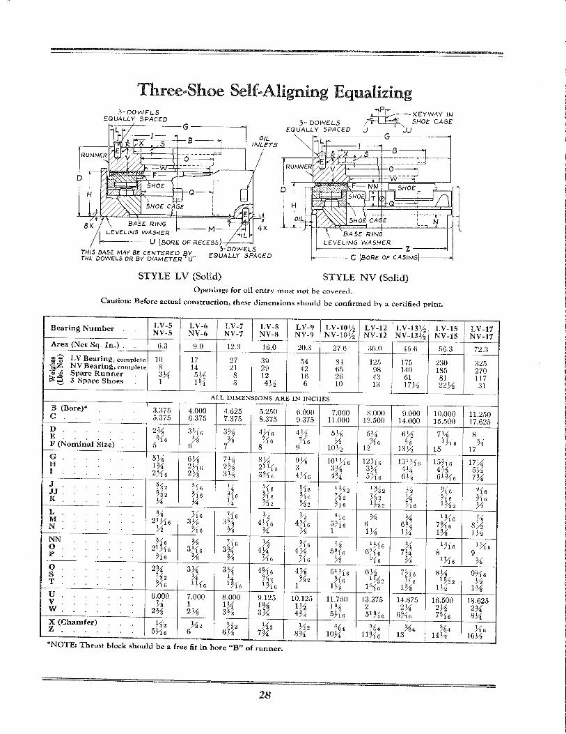
Three .. Shoe Self .. AHgning Equalizing 3-DOWELS
EQUALLY SPACED
1----- M --ri"i LEVELING WASHER L
f------ U (BORE OF RECESS) -;'----<>l 3-DOVIIELS
THIS BASE MAY BE CENTERED BY.. EQUALLY SPACED THE Downs OR BY DIAMETER "U
3- DOWELS EGlUALLY SPACED
.Lrr..---:---- K EYWA YIN ~~ SHOE CAGE J JJ
STYLE LV (Solid) STYLE NV (Solid) Openings for oil entry must not be covered.
Caution: Before actual construction, these dimensions should be confirmed by a certified print.
Bearing Number LV-S LV-o LV-7 LV-8 LV-9 LV -10% LV-12 LV-13 1/ Z LV-IS NV-S NV-6 NV-7 NV-8 NV-9 NV -10% NV-12 NV -131J2 NV-IS
Area (Net Sq. In.) . 6.3 9.0 12.3 16.0 20.3 27.6 36.0 4.5.6 .56.3
'" LV Bearing, complete 10 17 27 39 M 84 125 17.5 230 co .... .... ., il,Z NV Bearing, complete 8 14 21 29 42 6.5 98 140 185 eQj ~ Spare Runner 3).4 .5Y:; 8 12 16 26 43 61 81 ~:6 3 Spare Shoes 1 1~ 3 4Y:; 6 10 13 17Y:; 22Y:;
ALL DIMENSIONS ARE IN INCHES
B (Bore)* 3.37.5 4.000 4.625 .5.250 6.000 7.000 8.000 9.000 10.000 C .5.37.5 6.37.5 7.37.5 8.37.5 9.37.5 11.000 12.500 14.000 1.5 . .500
D 2% 3!"16 3 5/0 H16 4Y:; 5Y8 .5~ 6Y:; Hi /8 E ~16 % 3/ X6 X6 Y:; YI6 % 1 ;'16 . . . . . /8 F (Nominal Size) 5 6 7 8 9 lOY:; 12 13 Y:; 1.5
G 5% 6% 7% 8% 9% 101 ;16 12~16 131;'16 1.5~16 H 1% 2;'16 2% 21HG 3 3% 3~ 4).i 4% I 2%6 2% 3% 3~16 4;'16 4% .5H6 6% 61~16
J %2 ~16 ).4 ?16 ?lG 1%2 1%2 ;1 YIG JJ %2 ~16 ~lG ~16 ~lG ~32 ~32 ).4 ~'16 K ).4 ).4 )..4' ~:32 %2 ~16 1 }.32 ~16 1%2
L % ~16 ~16 Y:; ~ ?lG % ~ IJ16 M 21 VI6 3% 3% 4}.16 4;16 5~16 6 6~ 7YI6 N Y2 ~16 % % Ys 1 1% 1).i 1%
NN ~16 % ~{ 6 Y2 %6 % 1 ;'16 3/ 1716 /·1 0 21 VI6 3J16 3% 4).i 4% .5~16 6;{ 6 7).4 8 P ~{6 % % X6 :-1 G Y2 ~16 % 1 Yr6
Q 2% 3).4 3% 4%6 4Ys 51H6 6Y:; 7%6 8% s %2 ).4 )..4' %2 %2 ~16 1;'32 ~16 1%2 T ~16 IH6 1~{6 1%6 1 1% F{G 1% 1Y:;
U 6.000 7.000 8.000 9.125 10.125 11.7.50 13.375 14.875 16.500 V % 1 1).4 1% 1Y:; 1% 2 2)..4' 2Y:; w 2% 2% 3% 3% 4% 5}.{6 51%6 6YI6 7%6
X (Chamfer) %'2 732 ;'32 %2 %2 %4 %4 %4 %4 Z 5VI6 6 6% 7% 8% 10).4 llYI6 13 14Y:;
*NOTE: Thrust block should be a free fit in bore "B" of runner.
28
LV-17 NV-I7
72.3
32.5 270 117 31
11.250 17.62.5
8 %
17
17 )..4' .5)..4' 7~
%6 ~16 ~
% 8)/;i 1~
1~{6 9
%
9U6 Y2
1%
18.625 2% 8).4
}.{6 16Y:;
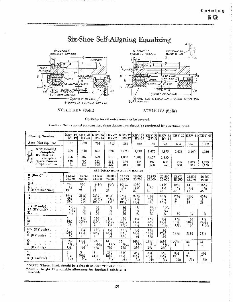
Six-,Shoe Self .. Aligning Equalizing
KeYWAY IN J1 ~ 6-DOWHS EGlUALLY SPACeD
€i-DOWE.LS EQUALLY SPACED 8ASE: R.ING
~~~~~_: l JJ
6-01L SLOTS .......t:4 .. L E EQUALLY SPACED I ... 30· FROM DOWc.LS.
F----- C(SORE OF RECESS)-/----<>I
6-DOWELS EQUALLY SPACE.D
6-01L SLOTS EQUALLY SPACED STARTING 30" FROM KEY
STYLE KBV (Split) STYLE BV (Split)
Openings for oil entry must not be covered.
Caution: Before actual construction, these dimensions should be confirmed by a certified print.
Bearing Number . KBV-19 KBV-21 KBV-23 KBV-25 KBV-27 KBV-29 BV-19 BV-21 BV-23 BV-25 BV-27 BV-29
Area (Net Sq. In.) 180 220 264 312 364 420
tl'Z' KBV Bearing, 399 512 635 826 1,020 1,218 complete
f.,~ BV Bearing, 396 507 629 818 1,007 1,203
~~ complete Spare Runner 159 195 223 312 364 426 6 Spare Shoes 91 122 165 227 242 305
ALL DIMENSIONS ARE IN INCHES
B (Bore)* 12.625 13.750 14.625 16.000 17.125 C. 20.250 22.250 24.500 26.500 28.750
D** 7% 8>4 81 716 9?l6 10716 E. . . . . % 1 1 1 1>4 F (Nominal Size) 19 21 23 25 27
G. 19J.i' 21>4 23>4 25>4 27>4 H. 4% 5>4 51 716 6~16 61 716 I . 8% 9Yz 10Yz 11Yz 12>4
J (BVonly) 1%2 Yz Yz % % JJ (BVonly) 1 ~~2 % % Yz Yz K. ~16 % % % %
L. 1 IVs IVs 1Vs 1% M. 9>4 10%6 11)16 12Yt6 13Yt6 N. Ys 1 1 IVs U16
NN (BV only) . 1 IVs 1~16 1% U16 o. lOVs 11Ys 12Ys 13>4 14>4 P (BVonly) Ys 1 1 1>4 1>4
Q. 10% 11% 12% 14 15 S. 1%2 1716 1716 1 ~16 1%6 T (BVonly) 1% 1% 2Ys 2>4 2%
V. 3 3 3 3% 3% w. 9J.i' 10J.i' llJ.i' 12J.i' 13>4 X (Cl~a~fe~) ~16 716 716 716 716
*NOTE: Thrust block should be a free fit in bore "B" of runnel'. ** Add to height D a suitable allowance for insulated sub·base if
needed.
29
18.000 30.750
lOYz 1>4
29
29% 7Ys
13>4
% Yz %
1% 14Ys
1>4
lYz 15Ys
1>4
16>4 IH6
2Yz
3% 14Ys
716
KBV-31 KBV-33 KBV-37 KBV-41 BV-31 BV-33
480 545 684 840
1,475 1,875 2,478 3,260
1,457 1,850
497 600 795 1,027 388 550 666 818
18.875 20.500 22.375 24.500 33.000 35.000 38.500 43.750
11 11% 12% 14 IJ.i' 1>4 IYz lYz
31 33 37 41
31% 33% 37Yz 41Yz 7% 8Ys 9 10
14>4 15>4 17 19
1~16 1~16 ~16 ~16 % % Ys Ys
1% 1% 1% 1% 15Ys 16Ys 18>4 20Ys 1% U16 1?l6 1%
1% 1% 16Ys 17>4 19Ys 21Ys lYz lYz
17J.i' 18Yz 20% 23 1~16 1~16 1 1
2% 2%
3% 3% 3% 4 15Ys 16Ys 18 20
716 %2 %2 %2
KBV-45
1012
4,310
1,275 1,150
26.750 48.000
15Vs lYz
45
45Yz 11 21
Ys 1%
22716 11%6
23Ys
25 1
4Vs 22
%2
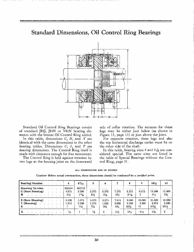
Standard Dimensions, Oil Control Ring Bearings
Standard Oil Control Ring Bearings consist of standard JBJ, JBN or NBN bearing elements with the bronze Oil Control Ring added.
In this table, dimensions C, H, and X are iden tical wi th the same dimensions in the other bearing tables. Dimensions C, S, and Tare housing dimensions. The Control Ring itself is made with clearance enough for free movement.
The Control Ring is held against rotation by two lugs at the housing joint on the downward
side of collar rotation. The recesses for these lugs may be either just below (as shown in Figure 15, page 13) or just above the joint.
For opposite rotation, these lugs and also the top horizontal discharge outlet must be on the other side of the shaft.
In this table, bearing sizes 4 and 4is are considered special. The same sizes are listed in the table of Special Bearings without the Control Ring, page 31.
ALL DIMENSIONS ARE IN INCHES
Caution: Before actual construction, these dimensions should be confirmed by a certified print.
Bearing Number . 4 4 7/16 5 (, '/ 8 9 101/2 12
Drawing Number 263554 462175 .... . .... . .... . . .... . . . . . . .... .... . C (Bore Housing) 4.875 5.500 5.375 6.375 7.375 8.375 9.375 11.000 12.500 H 1% 11% I%; 2Y!6 2% 21Y!6 3 3% 3%;
S (Bore Housing) 5.250 5.875 5.875 6.875 7.875 9.000 10.000 11.625 13.250 T (Housing) 1.375 2.250 1.375 1.625 2.000 2.250 2.500 2.875 3.250 U 7 774 7%; 8%; 9%; 1O%; 12 13%; 15~
X Ys 1 Ys 1 174 1% 1~ 1%; 2
30
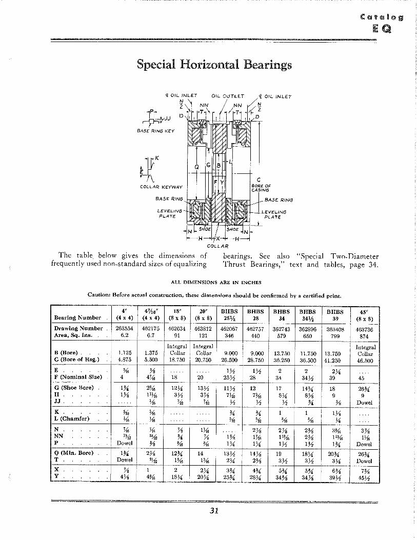
Special Horizontal Bearings
~JJ D
BASE RING KEY
COLLAR KEYWAY
BASE RING
LEVELING PLATE
COLLAR
C BORE Of: CASING
BASE: RING
LEVeLING PLATE
The table. below gives the dimensions of frequently used non-standard sizes of equalizing
bearings. See also "Special Two-Diameter Thrust Bearings," text and tables, page 34.
ALL DIMENSIONS ARE IN INCHES
Caution: Before actual construction, these dimensions should be confirmed by a certified print.
4" 47;16" 18" 20" BHBS BHBS BHBS BHBS BHBS 45" Bearing Number (4 x 4) (4 x 4) (8 x 8) (8 x 8) 25% 28 34 34% 39 (8 x 8)
Drawing Number 263554 462175 462634 463812 462067 462757 362743 362896 363408 463736 Area, Sq. Ins. 6.2 6.7 91 121 346 440 579 650 799 874
Integral Integral Integral B (Bore) . 1.125 1.375 Collar Collar 9.000 9.000 13.750 11.750 13.750 Collar C (Bore of Hsg.) 4.875 5.500 18.750 20.750 26.500 28.750 36.250 36.500 41.250 46.500
E % % .... . ..... lk; 171 2 2 234 ." . F (Nominal Size) 4 4U6 18 20 25k; 28 34 34k; 39 45
G (Shoe Bore) 1% 2% 1234 13 71 11k; 12 17 14% 18 26% H. 1% 11% 3k; 3Ys 7~ 7% 8 X;; 8% 9 9 JJ . ..... % ~ ~2 71 71 k; % % Dowel
K. ~ % .... . . . . . . % % 1 1 lYs ., .. L (Chamfer) ~6 l16 .... . . . . . . %1 ~ % :U6 34 ., .. N 'K6 'K6 Ys 1~6 ..... 2Ys 2Ys 2% 3% 3Ys NN 1%2 2~2 % Ys 1% 1'K6 11% 2% 11% 1116 P Dowel % % % IX;; IX;; lk; lk; 1% Dowel
Q (Min. Bore) 1% 2Ys 12% 14 13k; 14Ys 19 18 X;; 20% 26% T Dowel 2~ 1% 1% 234 2% 3k; 3k; 334 Dowel
X Ys 1 2 234 3% 4% 5% 5% 6% 7% Y 4Ys 4% 18 X;; 20 X;; 25% 2834 34% 34Ys 39k; 45k;
31
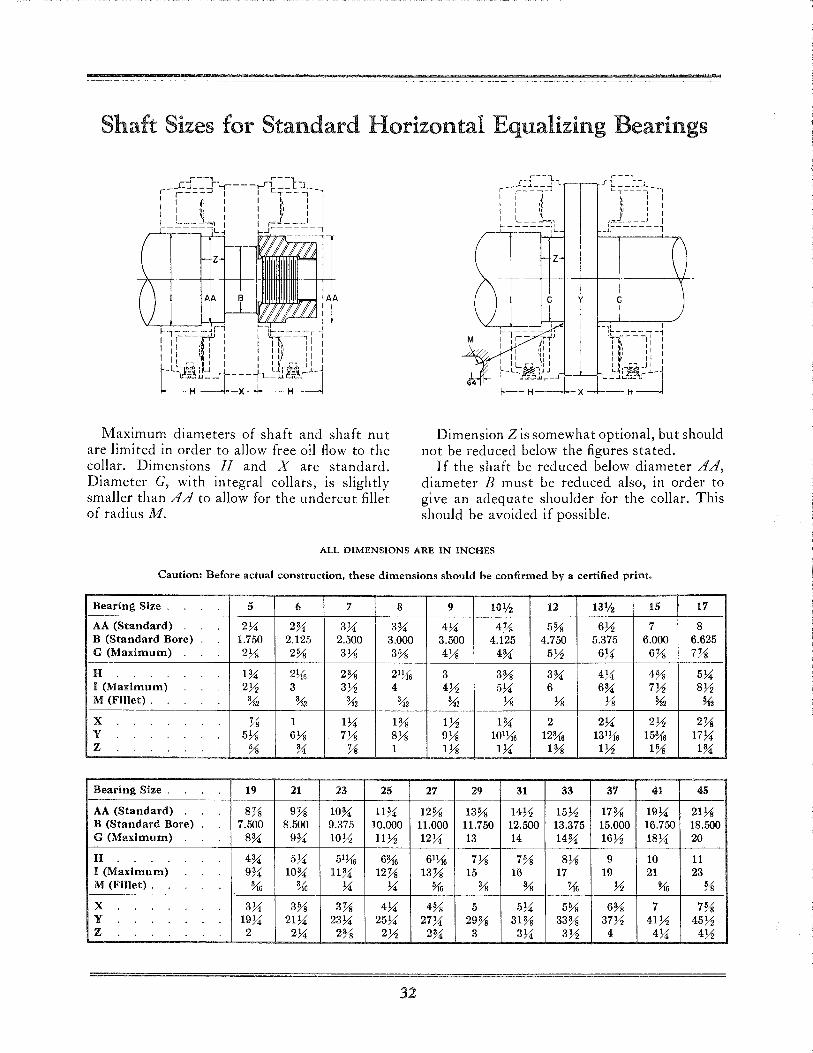
Shaft Sizes for Standard Horizontal Equalizing Bearings
Maximum diameters of shaft and shaft nut are limited in order to allow free oil flow to the collar. Dimensions H and X are standard. Diameter G, with integral collars, is slightly smaller than AA to allow for the undercut fillet of radius M.
z
M
l Dimension Z is somewhat optional, but should
not be reduced below the figures stated. If the shaft be reduced below diameter AA,
diameter B must be reduced also, in order to give an adequate shoulder for the collar. This should be avoided if possible.
ALL DIMENSIONS ARE IN INCHES
Caution: Before actual construction, these dimensions should be confirmed by a certified print.
Bearing Size . 5 (, 7 8 9 10% 12 13% 15 1'7
AA (Standard) 274 2~ 374 3~ 474 4Ys 5% 671 7 8 B (Standard Bore) 1.750 2.125 2.500 3.000 3.500 4.125 4.750 5.375 6.000 6.625 G (Maximum) 2Ys 2% 3Ys 3% 4Ys 4~ 571 674 6Ys 7Ys
H 1~ 2){6 2% 21){6 3 3% 3~ 474 4% 574 I (Maximum) 271 3 371 4 471 574 6 6~ 771 871 M (Fillet). :j,{2 %2 %2 %2 :j,{2 Ys Ys Ys ~ ~
X Ys 1 174 1% 171 1~ 2 274 271 2Ys Y 5Ys 6Ys 7Ys 8Ys 9Ys 101){6 12% 131Yt1; 15% 1774 z % ~ Ys 1 1Ys 174 1% 171 1% 1~
Bearing Size . 19 21 23 25 27 29 31 33 3'7 41 45
AA (Standard) 8Ys 9Ys 10~ 11~ 12% 13% 1471 1571 17% 1974 21Ys B (Standard Bore) 7.500 8.500 9.375 10.000 11.000 11.750 12.500 13.375 15.000 16.750 18.500 G (Maximum) 8~ 9~ 1071 1171 1274 13 14 14~ 1671 1874 20
H 4~ 574 51){6 6% 61){6 7Ys 7% 8Ys 9 10 11 I (Maximum) 9~ 1O~ 1l~ 12Ys 13Ys 15 16 17 19 21 23 M (Fillet). % % 74 74 91'6 % % ~ 71 % %
X 374 3% 3Ys 474 4% 5 574 5% 6% 7 7% Y 1974 2174 23 74 2574 2774 29% 31% 33% 3771 41 71 4571 z 2 274 2% 271 2~ 3 374 371 4 474 471
32
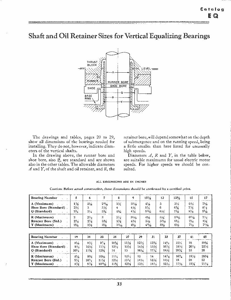
Shaft and Oil Retainer Sizes for Vertical Equalizing Bearings
RUNNER BORE SHOE BORE
I-fi+-------l-Q -
R--+---+i
f>!+---+-'y
The drawings and tables, pages 20 to 29, show all dimensions of the bearings needed for installing. They do not, however, indicate diameters of the vertical shafts.
In the drawing above, the runner bore and shoe bore, also IQ, are standard and are shown also in the other tables. The allowable diameters A and Y, of the shaft and oil retainer, and R, the
retainer bore, will depend somewhat on the depth of submergence and on the running speed, being a little smallel than here listed for unusually high speeds.
Diameters A, Rand Y, in the table below, are suitable maximums for usual electric motor speeds. For higher speeds we should be consulted.
ALL DIMENSIONS ARE IN INCHES
Caution: Before actual construction, these dimensions should be confirmed by a certified print.
Bearing Number 5 6 7 8 9 10% 12 131/ 2 15 17
A (Maximum) 1Ys 2§{6 21% 3y'! 31l{6 4§{6 5 5% 6% 7% Shoe Bore (Standard) . 2Yz 3 3Yz 4 4Yz 5y'! 6 6% 7Yz 8Yz Q (Standard) 2% 3y'! 3% 4%, 4Ys 51l{6 6Yz 7§{6 8Ys 9~6
R (Maximum) 2 2Yz 3 3~2 31§{6 4% 5y'! 51§{6 61l{6 7Yz Runner Bore (Std.) 2% 2Ys 3% 3Ys 4% 5l{6 51% 6% 7§{6 8y'! Y (Maximum) 2% 2% 3% 31l{6 4% 41% 5% 6§{6 7){6 71§{6
Bearing Number 19 21 23 25 27 29 31 33 37 41 45
A (Maximum) 8l{6 8Yz 9Ys 10% 11% 12Yz 13% 14% 167';; 18 19% Shoe Bore (Standard) . 9Yz lOYz llYz 12Yz 13Yz 14Yz 15Yz 16Yz 18~2 20Yz 22Yz Q (Standard) 10% 11% 12% 14 15 16y'! 17Y.! 18Yz 20% 23 25
R (Maximum) 8Yt6 9% 1O§{6 llY.! 12Ys 13 14 14Ys 16% 18Yz 20% Runner Bore (Std.) 9y'! lOy'! 11y'! 12Y.! 13y'! 147';; 157';; 16Ys 18 20 22 Y (Maximum) 8Ys 9Ys 101% 11% 12% 13% 14Yz 15Yz 17Ys 19y'! 21Ys
33
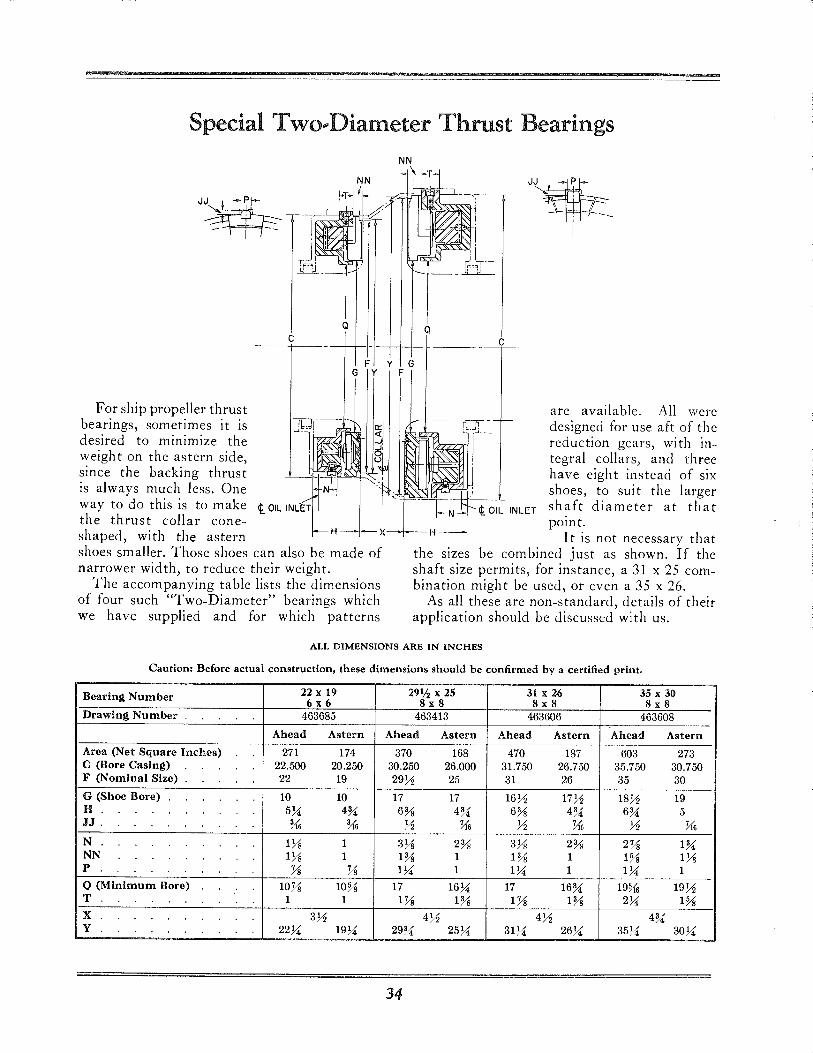
Special Two .. Diameter Thrust Bearings
For ship propeller thrust bearings, sometimes it is desired to minimize the weight on the astern side,
c
is always much less. One N
way to do this is to make t OIL INLET
the thrust collar cone-
Q
F G Y
since the backing thrust tl -
shaped, with the astern H x shoes smaller. Those shoes can also be made of narrower width, to reduce their weight.
The accompanying table lists the dimensions of four such "Two-Diameter" bearings which we have supplied and for which patterns
y G F
Q
c
JJ. ~" ' } -\--- -r--
i -
are available. All were designed for use aft of the reduction gears, with integral collars, and three have eight instead of six shoes, to suit the larger shaft diameter at that point.
I t is not necessary that sizes combined just as shown. If the
shaft size permi ts, for instance, a 31 x 25 combination might be used, or even a 35 x 26.
As all these are non-standard, details of their application should be discuss(;d with us.
ALL DIMENSIONS ARE IN INCHES
Caution: Before actual construction, these dimensions should be confirmed by a certified print.
Bearing Number 22 x 19 29% x 25 31 x 26 35 x 30 6x6 8x8 8x8 8x8
Drawing Number 463685 463413 463606 463608
Ahead Astern Ahead Astern Ahead Astern Ahead Astern
Area (Net Square Inches) 271 174 370 168 470 187 603 273 C (Bore Casing) 22.500 20.250 30.250 26.000 31.750 26.750 35.750 30.750 F (Nominal Size) 22 19 29Yz 25 31 26 35 30
G (Shoe Bore) 10 10 17 17 16Yz 17Yz 18Yz 19 H. 5%: 4U 6% 4U 6% 4U 6U 5 JJ . % % Yz ~6 Yz ~6 Yz Us N 1% 1 3% 2% 3% 2% 2Ys lU NN 1% 1 1% 1 1% 1 1% 1% p Ys Ys I%: 1 I%: 1 I%: 1
Q (Minimum Bore) IOYs 10% 17 16%: 17 16U 19Vt6 19Yz T 1 1 lYs 1% lYs 1% 2%: 1% X 3Yz 4Yz 4Yz 4U Y 22%: 19%: 29U 25%: 31%: 26%: 35%: 30%:
34
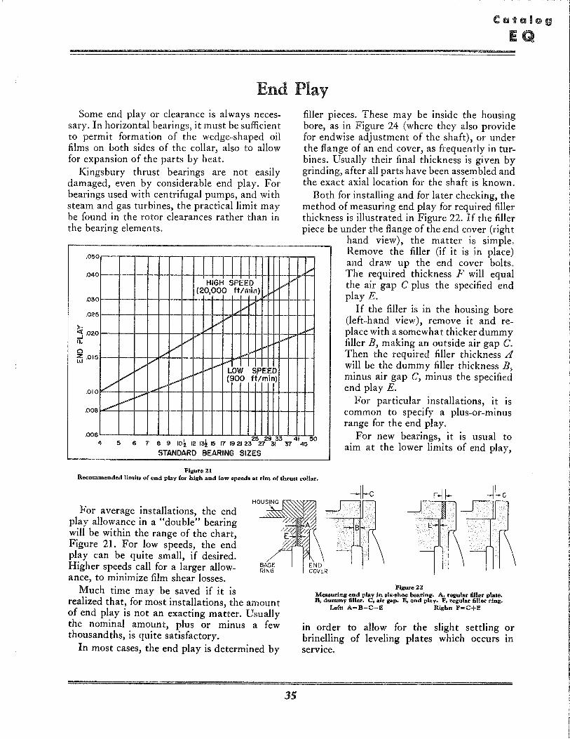
End Play Some end play or clearance is always neces
sary. In horizontal bearings, it must be sufficient to permit formation of the wedge-shaped oil films on both sides of the collar, also to allow for expansion of the parts by heat.
Kingsbury thrust bearings are not easily damaged, even by considerable end play. For bearings used with centrifugal pumps, and with steam and gas turbines, the practical limit may be found in the rotor clearances rather than in the bearing elements.
.050
.040
. 030
.025
~ .020 a.. o r.5 .015
.010
.008
/' .,/
V /'
/'
,/'" V
V ./ "..". V
V /
HIGH SPEED !-'V (20,000 ftlmin) I-"
./ vI-"
,./ V V
I-"i-"i-" f"'~
""'" ~ i--'" .... LOW S,PEED V (900 ftlmin)
V
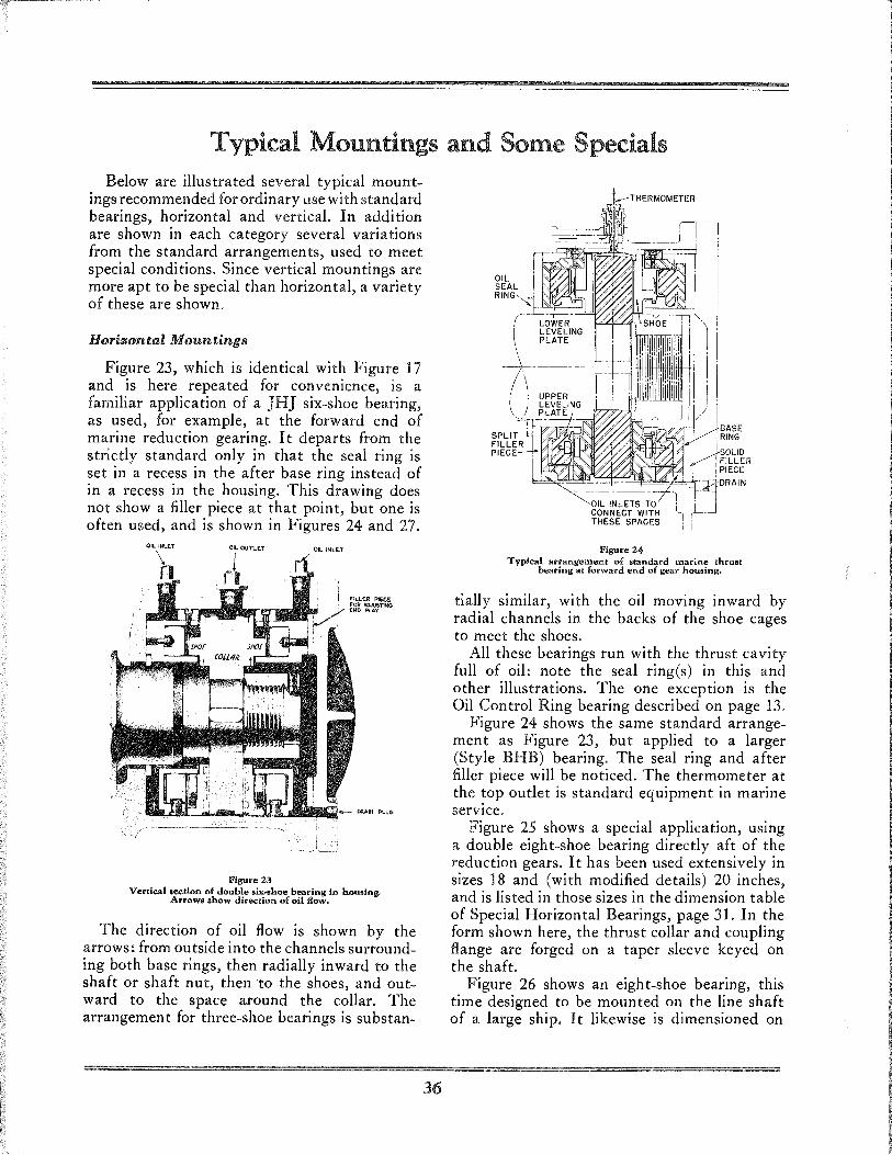
filler pieces. These may be inside the housing bore, as in Figure 24 (where they also provide for endwise adjustment of the shaft), or under the flange of an end cover, as frequently in turbines. Usually their final thickness is given by grinding, after all parts have been assembled and the exact axial location for the shaft is known.
Both for installing and for later checking, the method of measuring end play for required filler thickness is illustrated in Figure 22. If the filler piece be under the flange of the end cover (righ t
,/
~
hand view), the matter is simple. Remove the filler (if it is in place) and draw up the end cover bolts. The required thickness F will equal the air gap C plus the specified end play E .
If the filler is in the housing bore (left-hand view), remove it and replace with a somewhat thicker dummy filler B, making an outside air gap C. Then the required filler thickness A will be the dummy filler thickness B, minus air gap C, minus the specified end play E.
For particular installations, it is common to specify a plus-or-minus range for the end play.
.006 4
25 29 33 41 50 8 9 10k 12 13115 17 19 21 23 27 31 '57 45
For new bearings, it is usual to aim at the lower limits of end play, 5 6 7
STANDARD BEARING SIZES
Figure 21 Recommended limits of end play (or high and low speed. at rim of thrust collar.
For average installations, the end play allowance in a "double" bearing will be within the range of the chart, Figure 21. For low speeds, the end play can be quite small, if desired. Higher speeds call for a larger allowance, to minimize film shear losses.
Much time may be saved if it is realized that, for most installations, the amount of end play is not an exacting matter. Usually the nominal amount, plus or minus a few thousandths, is quite satisfactory.
In most cases, the end play is determined by
35
Figure 22 Measuring end play in .ix .. hoe bearing. A, regular filler plate. B, dummy filler. C, air gap. E, end plav. F, regular filler ring.
Left! A-B-C-E Right! F-C+E
in order to allow for the sligh t settling or brin~lling of leveling plates which occurs in
service.
Typical Mountings and Some Specials Below are illustrated several typical mount
ings recommended for ordinary use wi th standard bearings, horizontal and vertical. In addition are shown in each category several variations from the standard arrangements, used to meet special conditions. Since vertical mountings are more apt to be special than horizontal, a variety of these are shown.
Horizontal Mountings
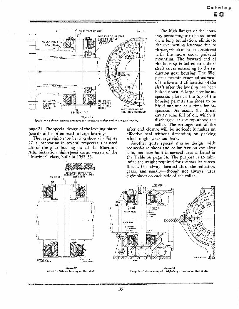
Figure 23, which is identical with Figure 17 and is here repeated for convenience, is a familiar application of a JHJ six-shoe bearing, as used, for example, at the forward end of marine reduction gearing. It departs from the strictly standard only in that the seal ring is set in a recess in the after base ring instead of in a recess in the housing. This drawing does not show a filler piece at that point, but one is often used, and is shown in Figures 24 and 27.
OIL. INLET OIL OU11.ET
Figure 23
OIL INLE.T
FIL.LER PiECE FOR AOJ05T1NG END PlA.Y
Vertical section of double .ix .. hoe bearing in housing. Arrow8 ahow direction of oil flow.
The direction of oil flow is shown by the arrows: from outside into the channels surrounding both base rings, then radially inward to the shaft or shaft nut, then -to the shoes, and outward to the space around the collar. The arrangement for three-shoe bearings is substan-
36
Figure 24 Tvpical arrangement of standard marine thrust
bearing at forward end of gear housing.
tially similar, with the oil moving inward by radial channels in the backs of the shoe cages to meet the shoes.
All these bearings run with the thrust cavity full of oil: note the seal ring(s) in this and other illustrations. The one exception is the Oil Control Ring bearing described on page 13.
Figure 24- shows the same standard arrangement as Figure 23, but applied to a larger (Style BHB) bearing. The seal ring and after filler piece will be noticed. The thermometer at the top outlet is standard equipment in marine service.
Figure 25 shows a special application, using a double eight-shoe bearing directly aft of the reduction gears. I t has been used extensively in sizes 18 and (with modified details) 20 inches, and is listed in those sizes in the dimension table of Special Horizontal Bearings, page 31. In the form shown here, the thrust collar and coupling flange are forged on a taper sleeve keyed on the shaft.
Figure 26 shows an eight-shoe bearing, this time designed to be moun ted on the line shaft of a large ship. It likewise is dimensioned on
FILLER I
I' r~~-=: ",." "-C--
~ -~~-,~~,-------t-, I
! F== --K-EY-'J(~r ___ --=-~-_-+-r--- --'~,-, ,r-,-1~'
/ ' '1 1=1-- OIL INLET ~, , t' -1' CONNECTS
WITH THIS , SPACE
Figure 25
OIL INLET CONNECTS WITH THIS SPACE
PART SECTION, BB ONE SHOE REMOVED
Special 8 x 8 thrust bearing, arranged for mounting at after end of the gear housingo
The high flanges of the housing, permitting it to be mounted on a long foundation, eliminate the overturning leverage due to thrust, which must be considered wi th the more usual pedestal mounting. The forward end of the housing is bolted to a short shaft cover extending to the reduction gear housing. The filler pieces permit exact adjustment of the fore-and-aft location of the shaft after the housing has been bolted down. A large circular inspection plate in the top of the housing permits the shoes to be lifted out one at a time for inspection. As usual, the thrust cavity runs full of oil, which is discharged at the top above the collar. The arrangement of the
page 31. The special design of the leveling plates (see detail) is often used in large bearings.
The large eight-shoe bearing shown in Figure 27 is interesting in several respects: it is used aft of the gear housing on all the Maritime Administration high-speed cargo vessels of the "Mariner" class, built in 1952-53.
DEVELOPED SECTION THRU CENTER OF LEVELING PLATES
AND SHOES
Figure 26 Large 8 '" 8 th.".! bearing 0" Ii"" .haft.
37
after end closure will be noticed: it makes an effective seal without depending on packing which might wear and leak.
Another quite special marine design, with reduced-size shoes and collar face on the after side, has been built in several sizes as listed in the Table on page 34. The purpose is to minimize the weight required for the smaller astern thrust. It is always located aft of the reduction gears, and usually-though not always-uses eight shoes on each side of the collar.
Figure 27 Larg" 8 " 8 thrUS! unit, with high.fI""g" ho,,';ng 0", Ii .. " .halt.
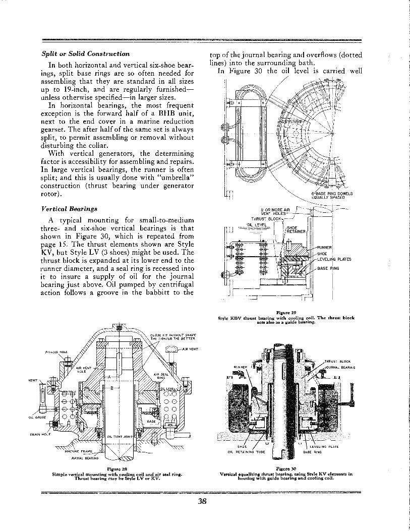
Split or Solid Construction
In both horizontal and vertical six-shoe bearings, split base rings are so often needed for assembling that they are standard in all sizes up to 19-inch, and are regularly furnishedunless otherwise specified-in larger sizes.
In horizontal bearings, the most frequent exception is the forward half of a BHB unit, next to the end cover in a marine reduction gearset. The after half of the same set is always split, to permit assembling or removal without disturbing the collar.
With vertical generators, the determining factor is accessibility for assembling and repairs. In large vertical bearings, the runner is often split; and this is usually done with "umbrella" construction (thrust bearing under generator rotor).
Vertical Bearings
A typical mounting for small-to-medium three- and six-shoe vertical bearings is that shown in Figure 30, which is repeated from page 15. The thrust elements shown are Style KV, but Style LV (3 shoes) might be used. The thrust block is expanded at its lower end to the runner diameter, and a seal ring is recessed into it to insure a supply of oil for the journal bearing just above. Oil pumped by centrifugal action follows a groove in the babbitt to the
Figure 28 Simple vertical mounting with cooling coil and air oeal ring.
Thrust bearing may be Style LV or KV.
38
top of the journal bearing and overflows (dotted lines) into the surrounding bath.
In Figure 30 the oil level is carried well
//
'~ 6-BASE RING DOWELS ~ EQUALLY ~PACED
2 OR MORE AIR r-'~f:l-----'~ ..------.. THRU~~N;L~~~t:ESj rnt:" -~--
-OIL LEVEL ! I' 'III ____ - , SHOE /"
--~~J, ': RETAINER Iii ' . ' . ,--1- ,j::, RUNNER I
~~~~U1G PLATES
BASE ~ING
Figure 29 Style KBV thrust bearing with cooling coil. The thruat block
act. allo al a guide bearing.
Figure 30 Vertical equalizing thruat bearing, using Style KV elements in
houling with guide bearing and cooling coil.
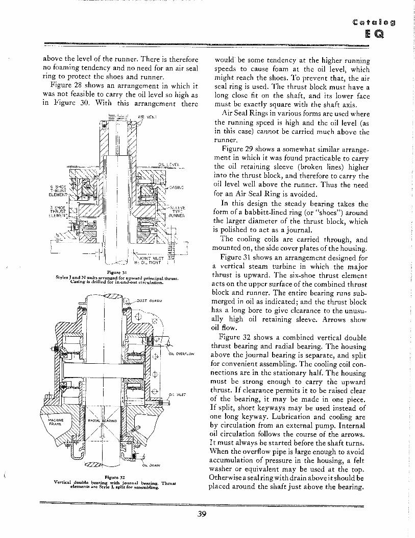
above the level of the runner. There is therefore no foaming tendency and no need for an air seal ring to protect the shoes and runner.
Figure 28 shows an arrangement in which it was not feasible to carry the oil level so high as in Figure 30. With this arrangement there
Figure 31 Styles J and N units arranged for upward principal thrust.
Casing is drilled for in-and~ut circulation.
Figure 32 Vertical double bearing with journal bearing. Thru8t
element. are Style J. spHt for assembling.
39
would be some tendency at the higher running speeds to cause foam at the oil level, which might reach the shoes. To prevent that, the air seal ring is used. The thrust block must have a long close fi t on the shaft, and its lower face must be exactly square with the shaft axis.
Air Seal Rings in various forms are used where the running speed is high and the oil level (as in this case) cannot be carried much above the runner.
Figure 29 shows a somewhat similar arrangement in which it was found practicable to carry the oil retaining sleeve (broken lines) higher into the thrust block, and therefore to carry the oillevel well above the runner. Thus the need for an Air Seal Ring is avoided.
In this design the steady bearing takes the form of a babbitt-lined ring (or "shoes") around the larger diameter of the thrust block, which is polished to act as a journal.
The cooling coils are carried through, and mounted on, the side cover plates of the housing.
Figure 31 shows an arrangement designed for a vertical steam turbine in which the major thrust is upward. The six-shoe thrust element acts on the upper surface of the combined thrust block and runner. The entire bearing runs submerged in oil as indicated; and the thrust block has a long bore to give clearance to the unusually high oil retaining sleeve. Arrows show oil flow.
Figure 32 shows a combined vertical double thrust bearing and radial bearing. The housing above the journal bearing is separate, and split for convenient assembling. The cooling coil connections are in the stationary half. The housing must be strong enough to carry the upward thrust, If clearance permits it to be raised clear of the bearing, it may be made in one piece, If split, short keyways may be used instead of one long keyway, Lubrication and cooling are by circulation from an external pump, Internal oil circulation follows the course of the arrows, It must always be started before the shaft turns, When the overflow pipe is large enough to avoid accumulation of pressure in the housing, a felt washer or equivalent may be used at the top, Otherwise a seal ring wi th drain above it should be placed around the shaft just above the bearing,
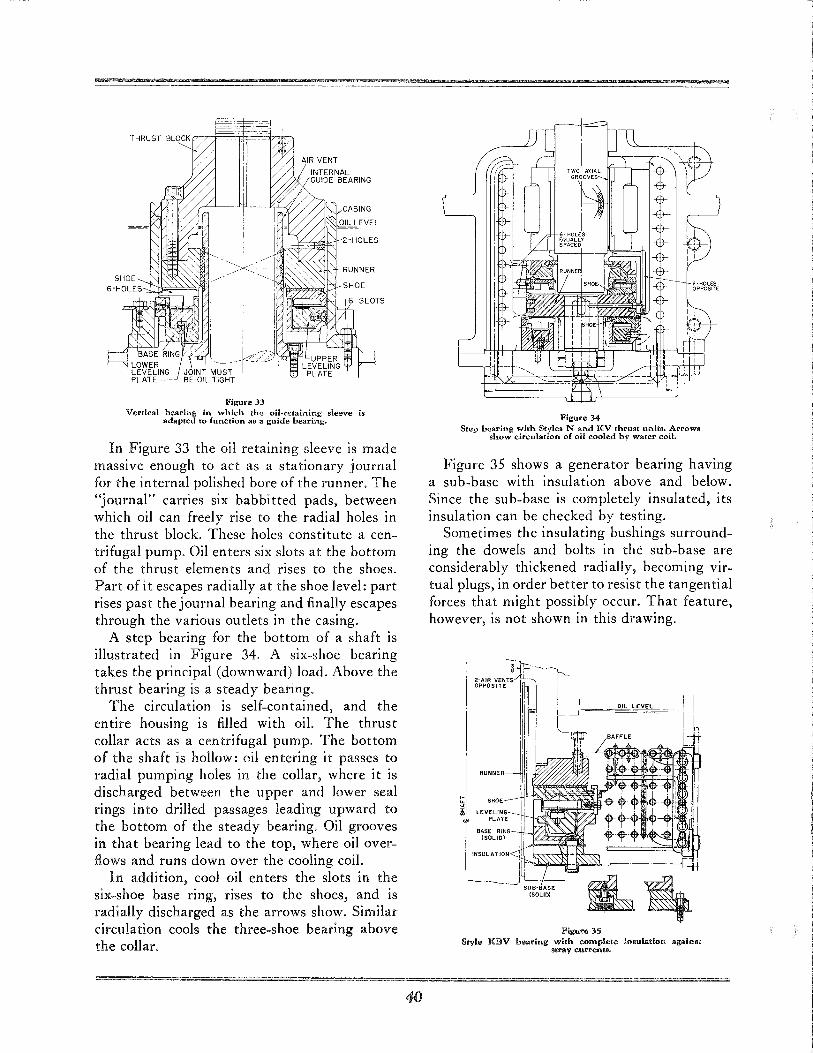
Figure 33 Vertical bearing in which the oil .. retaining sleeve is
adapted to funetion as a guide bearing.
In Figure 33 the oil retaining sleeve is made massive enough to act as a stationary journal for the internal polished bore of the runner. The "journal" carries six babbitted pads, between which oil can freely rise to the radial holes in the thrust block. These holes constitute a centri fugal pump. Oil en ters six slots at the bottom of the thrust elements and rises to the shoes. Part of it escapes radially at the shoe level: part rises past the journal bearing and finally escapes through the various outlets in the casing.
A step bearing for the bottom of a shaft is illustrated in Figure 34. A six-shoe bearing takes the principal (downward) load. Above the thrust bearing is a steady bearing.
The circulation is self-contained, and the entire housing is filled with oil. The thrust collar acts as a centrifugal pump. The bottom of the shaft is hollow: oil entering it passes to radial pumping holes in the collar, where it is discharged between the upper and lower seal rings into drilled passages leading upward to the bottom of the steady bearing. Oil grooves in that bearing lead to the top, where oil overflows and runs down over the cooling coil.
In addition, cool oil enters the slots in the six-shoe base ring, rises to the shoes, and is radially discharged as the arrows show. Similar circulation cools the three-shoe bearing above the collar.
40
Figure 34 Step bearing with Styles Nand KV thrust unit •• Arrows
show circulation of oil cooled by water coil.
Figure 35 shows a generator bearing having a sub-base with insulation above and below. Since the sub-base is completely insulated, its insulation can be checked by testing.
Sometimes the insulating bushings surrounding the dowels and bolts in the sub-base are considerably thickened radially, becoming virtual plugs, in order better to resist the tangential forces that might possibly occur. That feature, however, is not shown in this drawing.
Figure 35 Style KBV bearing with complete i" ... lation again.t
strav currents ..
Spare Parts
A Kingsbury Bearing correctly chosen, properly aligned and supplied with clean oil, is practically indestructi ble for the life of the ship. However, spare parts are customarily provided as a matter of insurance.
For marine machinery, American Bureau of Shipping rules will usually determine what spare parts are required. These regularly include thrust
shoes, occasionally thrust collars, also journal bearing shells and cooler parts where fi tted.
For other applications, it is usually sufficient to stock thrust shoes, and thrust collars or runners.
The other parts of the bearing practically never need replacement. Therefore, there is no need to carry complete bearings as spares.
Data Needed for Ordering
To make specific recommendations, we should have the fullest possible information on conditions to be met, as follows:
(A) Thrust load, maximum.
(B) Revolutions per minute, maximum.
(C) Shaft diameter (see pages 32 - 33).
(D) Will thrust collar be integral with shaft?
(E) Solid or split base rings? (Six-shoe only).
(F) Is cooling water available?
(G) Is external lubricating system available?
(H) Give space limitations, where applicable.
If, for any kind of application, the thrust load is not known, some sort of estimate must be made.
For propeller thrusts, we can make a sufficiently close estimate if given the following particulars:
Single, twin or multiple screws?
Maximum s.h. p. per shaft, and corresponding vessel speed, running free (not towing).
Propeller diameter, pitch and number of blades.
For dredge pump thrusts we should have also the impeller diameter, and the diameter of the suction opening 01' "eye" in the impeller.
Standard Guarantee
Any bearing or part furnished by us, which shall prove defective in design, material or workmanship, within one year after installation and test, will be replaced without charge f.o.b. Philadelphia, if returned to our factory. No allowance will be made for labor or other
41
expense in connection therewith unless authorized in writing by an officer of the Company.
For oil coolers and cooling coils, in accordance with usual trade practice, there is no specific guarantee period.