Kinetix 300 EtherNet/IP Indexing Servo Drives User … Downloads/2097-um001_-en-p.pdf · Kinetix...
192
Kinetix 300 EtherNet/IP Indexing Servo Drives Catalog Numbers 2097-V31PR0, 2097-V31PR2, 2097-V32PR0, 2097-V32PR2, 2097-V32PR4, 2097-V33PR1, 2097-V33PR3, 2097-V33PR5, 2097-V33PR6, 2097-V34PR3, 2097-V34PR5, 2097-V34PR6 User Manual
Transcript of Kinetix 300 EtherNet/IP Indexing Servo Drives User … Downloads/2097-um001_-en-p.pdf · Kinetix...

Kinetix 300 EtherNet/IP Indexing Servo Drives
Catalog Numbers 2097-V31PR0, 2097-V31PR2, 2097-V32PR0, 2097-V32PR2, 2097-V32PR4, 2097-V33PR1, 2097-V33PR3, 2097-V33PR5, 2097-V33PR6, 2097-V34PR3, 2097-V34PR5, 2097-V34PR6
User Manual

Important User InformationSolid state equipment has operational characteristics differing from those of electromechanical equipment. Safety Guidelines for the Application, Installation and Maintenance of Solid State Controls (publication SGI-1.1 available from your local Rockwell Automation sales office or online at http://www.rockwellautomation.com/literature/) describes some important differences between solid state equipment and hard-wired electromechanical devices. Because of this difference, and also because of the wide variety of uses for solid state equipment, all persons responsible for applying this equipment must satisfy themselves that each intended application of this equipment is acceptable.
In no event will Rockwell Automation, Inc. be responsible or liable for indirect or consequential damages resulting from the use or application of this equipment.
The examples and diagrams in this manual are included solely for illustrative purposes. Because of the many variables and requirements associated with any particular installation, Rockwell Automation, Inc. cannot assume responsibility or liability for actual use based on the examples and diagrams.
No patent liability is assumed by Rockwell Automation, Inc. with respect to use of information, circuits, equipment, or software described in this manual.
Reproduction of the contents of this manual, in whole or in part, without written permission of Rockwell Automation, Inc., is prohibited.
Throughout this manual, when necessary, we use notes to make you aware of safety considerations.
Allen-Bradley, CompactLogix, ControlFLASH, ControlLogix, Kinetix, MP-Series, TL-Series, RSLogix 5000, SoftLogix, Rockwell Automation, Rockwell Software, Stratix 6000, MicroLogix, Logix5000 and TechConnect are trademarks of Rockwell Automation, Inc.
Trademarks not belonging to Rockwell Automation are property of their respective companies.
WARNINGIdentifies information about practices or circumstances that can cause an explosion in a hazardous environment, which may lead to personal injury or death, property damage, or economic loss.
IMPORTANT Identifies information that is critical for successful application and understanding of the product.
ATTENTIONIdentifies information about practices or circumstances that can lead to personal injury or death, property damage, or economic loss. Attentions help you identify a hazard, avoid a hazard, and recognize the consequence
SHOCK HAZARDLabels may be on or inside the equipment, for example, a drive or motor, to alert people that dangerous voltage may be present.
BURN HAZARDLabels may be on or inside the equipment, for example, a drive or motor, to alert people that surfaces may reach dangerous temperatures.

Table of Contents
PrefaceAbout This Publication . . . . . . . . . . . . . . . . . . . . . . . . . . . . . 9Who Should Use This Manual . . . . . . . . . . . . . . . . . . . . . . . . 9Conventions Used in This Manual . . . . . . . . . . . . . . . . . . . . . 9Additional Resources. . . . . . . . . . . . . . . . . . . . . . . . . . . . . . 10
Chapter 1Start Introduction . . . . . . . . . . . . . . . . . . . . . . . . . . . . . . . . . . . . 11
About the Kinetix 300 Drive System. . . . . . . . . . . . . . . . . . . 12Catalog Number Explanation . . . . . . . . . . . . . . . . . . . . . . . . 14Agency Compliance . . . . . . . . . . . . . . . . . . . . . . . . . . . . . . 15
CE Requirements . . . . . . . . . . . . . . . . . . . . . . . . . . . . . . 15
Chapter 2Installing the Kinetix 300 Drive System
Introduction . . . . . . . . . . . . . . . . . . . . . . . . . . . . . . . . . . . . 17System Design Guidelines . . . . . . . . . . . . . . . . . . . . . . . . . . 18
System Mounting Requirements . . . . . . . . . . . . . . . . . . . 18Transformer Selection . . . . . . . . . . . . . . . . . . . . . . . . . . 19Circuit Breaker/Fuse Selection . . . . . . . . . . . . . . . . . . . . 19Sizing the Enclosure. . . . . . . . . . . . . . . . . . . . . . . . . . . . 20Minimum Clearance Requirements . . . . . . . . . . . . . . . . . 21
Minimizing Electrical Noise . . . . . . . . . . . . . . . . . . . . . . . . . 22Bonding Drives . . . . . . . . . . . . . . . . . . . . . . . . . . . . . . . 22Bonding Multiple Subpanels. . . . . . . . . . . . . . . . . . . . . . 24Establishing Noise Zones . . . . . . . . . . . . . . . . . . . . . . . . 25Cable Categories for Kinetix 300 Drive Components . . . . 27Noise Reduction Guidelines for Drive Accessories . . . . . . 27
Mounting Your Kinetix 300 Drive . . . . . . . . . . . . . . . . . . . . 30
Chapter 3Kinetix 300 Drive Connector Data Introduction . . . . . . . . . . . . . . . . . . . . . . . . . . . . . . . . . . . . 31
Kinetix 300 Drive Connectors and Indicators . . . . . . . . . . . . 32Safe Torque-off Pinout . . . . . . . . . . . . . . . . . . . . . . . . . . 34I/O (IOD) Connector Pinout. . . . . . . . . . . . . . . . . . . . . . 35Back-up Power Pinout . . . . . . . . . . . . . . . . . . . . . . . . . . 37Shunt Resistor and DC Bus Pinout . . . . . . . . . . . . . . . . . 37Motor Power Pinout. . . . . . . . . . . . . . . . . . . . . . . . . . . . 37
Understanding Motor Feedback Specifications . . . . . . . . . . . 38Motor Feedback Specifications . . . . . . . . . . . . . . . . . . . . 39Feedback Power Supply. . . . . . . . . . . . . . . . . . . . . . . . . 43
Understanding Control Signal Specifications . . . . . . . . . . . . . 44Digital Inputs. . . . . . . . . . . . . . . . . . . . . . . . . . . . . . . . . 44Digital Outputs . . . . . . . . . . . . . . . . . . . . . . . . . . . . . . . 48Analog Reference Input . . . . . . . . . . . . . . . . . . . . . . . . . 49
3Publication 2097-UM001A-EN-P - February 2010 3

Table of Contents
Analog Output. . . . . . . . . . . . . . . . . . . . . . . . . . . . . . . . 49Ethernet Connection . . . . . . . . . . . . . . . . . . . . . . . . . . . 5024V DC Back-Up Power. . . . . . . . . . . . . . . . . . . . . . . . . 51
Chapter 4Connecting the Kinetix 300 Drive System
Introduction . . . . . . . . . . . . . . . . . . . . . . . . . . . . . . . . . . . . 53Understanding Basic Wiring Requirements . . . . . . . . . . . . . . 53
Building Your Own Cables. . . . . . . . . . . . . . . . . . . . . . . 54Routing Power and Signal Wiring . . . . . . . . . . . . . . . . . . 54Determining Your Type of Input Power . . . . . . . . . . . . . 55Three-phase Power Wired to Three-phase Drives . . . . . . 55Single-phase Power Wired to Single-phase Drives . . . . . . 57Isolation Transformer in Grounded Power Configurations 58Three-phase Power Wired to Single-phase Drives . . . . . . 58Voiding of CE Compliance . . . . . . . . . . . . . . . . . . . . . . . 60
Grounding Your Kinetix 300 Drive . . . . . . . . . . . . . . . . . . . 61Grounding Your System to the Subpanel . . . . . . . . . . . . 61
Power Wiring Requirements . . . . . . . . . . . . . . . . . . . . . . . . 63Wiring Guidelines . . . . . . . . . . . . . . . . . . . . . . . . . . . . . . . . 65Wiring the Kinetix 300 Drive Connectors . . . . . . . . . . . . . . . 66
Wiring the Safe Torque-off (STO) Connector. . . . . . . . . . 66Wiring the Back-up Power (BP) Connector . . . . . . . . . . . 66Wiring the Input Power (IPD) Connector . . . . . . . . . . . . 67Wiring the Motor Power (MP) Connector . . . . . . . . . . . . 68Wiring the Shunt Resistor . . . . . . . . . . . . . . . . . . . . . . . . 73
Apply the Motor Cable Shield Clamp . . . . . . . . . . . . . . . . . . 74Understanding Feedback and I/O Cable Connections . . . . . . 75
Flying-lead Feedback Cable Pin-outs. . . . . . . . . . . . . . . . 76Wiring I/O Connector . . . . . . . . . . . . . . . . . . . . . . . . . . 77
Wiring Feedback Connector . . . . . . . . . . . . . . . . . . . . . . . . 78Wiring Low-profile Connector Kit . . . . . . . . . . . . . . . . . . 78
Understanding Shunt Resistor Connections. . . . . . . . . . . . . . 79Connecting Your Ethernet Cables . . . . . . . . . . . . . . . . . . . . 80
Chapter 5Configure and Start Up the Kinetix 300 Drive
Introduction . . . . . . . . . . . . . . . . . . . . . . . . . . . . . . . . . . . . 81Keypad Input . . . . . . . . . . . . . . . . . . . . . . . . . . . . . . . . . . . 82
Status Indicators. . . . . . . . . . . . . . . . . . . . . . . . . . . . . . . 83Configure the Kinetix 300 Drive Ethernet IP Address . . . . . . 84
Ethernet Connection . . . . . . . . . . . . . . . . . . . . . . . . . . . 84Kinetix 300 Drive Ethernet Port Configuration . . . . . . . . . 84Obtaining the Kinetix 300 Drives’ Current Ethernet Settings . . . . . . . . . . . . . . . . . . . . . . . . . . . . . . 85Configuring the IP Address Manually (static address). . . . 85
4 Publication 2097-UM001A-EN-P - February 2010

Table of Contents
Configuring the IP Address Automatically (dynamic address) . . . . . . . . . . . . . . . . . . . . . . . . . . . . . 87
Use the Kinetix 300 MotionView OnBoard Tool . . . . . . . . . . 89Kinetix 300 MotionView OnBoard Menu . . . . . . . . . . . . . . . 90Configuring Drive Using Kinetix 300 MotionView OnBoard Software . . . . . . . . . . . . . . . . . . . . . . . . . . . . . . . . . . 91
Drive Identification . . . . . . . . . . . . . . . . . . . . . . . . . . . . 91Motor . . . . . . . . . . . . . . . . . . . . . . . . . . . . . . . . . . . . . . 91General . . . . . . . . . . . . . . . . . . . . . . . . . . . . . . . . . . . . . 92Ethernet Communication . . . . . . . . . . . . . . . . . . . . . . . . 92Digital I/O. . . . . . . . . . . . . . . . . . . . . . . . . . . . . . . . . . . 93Analog I/O . . . . . . . . . . . . . . . . . . . . . . . . . . . . . . . . . . 93Velocity Limits . . . . . . . . . . . . . . . . . . . . . . . . . . . . . . . . 94Position Limits . . . . . . . . . . . . . . . . . . . . . . . . . . . . . . . . 94Dynamics . . . . . . . . . . . . . . . . . . . . . . . . . . . . . . . . . . . 95Indexing . . . . . . . . . . . . . . . . . . . . . . . . . . . . . . . . . . . . 95Homing. . . . . . . . . . . . . . . . . . . . . . . . . . . . . . . . . . . . . 96Tools. . . . . . . . . . . . . . . . . . . . . . . . . . . . . . . . . . . . . . . 96Monitor . . . . . . . . . . . . . . . . . . . . . . . . . . . . . . . . . . . . . 96Faults . . . . . . . . . . . . . . . . . . . . . . . . . . . . . . . . . . . . . . 96
Configure the Logix EtherNet/IP Interface Module . . . . . . . . 97Configure the Logix Controller . . . . . . . . . . . . . . . . . . . . 97Configure the Logix Module . . . . . . . . . . . . . . . . . . . . . . 98Configure the Kinetix 300 Drive . . . . . . . . . . . . . . . . . . . 99Download the Program . . . . . . . . . . . . . . . . . . . . . . . . 100
Apply Power to the Kinetix 300 Drive . . . . . . . . . . . . . . . . 101Test and Tune the Axis . . . . . . . . . . . . . . . . . . . . . . . . . . . 102Tune the Axis . . . . . . . . . . . . . . . . . . . . . . . . . . . . . . . . . . 103Select Drive Operating Mode. . . . . . . . . . . . . . . . . . . . . . . 105Configure Master Gearing Mode . . . . . . . . . . . . . . . . . . . . 106Configure Drive Parameters and System Variables . . . . . . . 108
Tools for Viewing Parameters . . . . . . . . . . . . . . . . . . . . 108Tools for Changing Parameters . . . . . . . . . . . . . . . . . . . 110
Configuring Drive Mode Using Explicit Messaging . . . . . . . 111
Chapter 6Troubleshooting the Kinetix 300 Drive System
Introduction . . . . . . . . . . . . . . . . . . . . . . . . . . . . . . . . . . . 115Safety Precautions . . . . . . . . . . . . . . . . . . . . . . . . . . . . . . . 115General Troubleshooting. . . . . . . . . . . . . . . . . . . . . . . . . . 116
Display Behavior . . . . . . . . . . . . . . . . . . . . . . . . . . . . . 116Error Codes . . . . . . . . . . . . . . . . . . . . . . . . . . . . . . . . . 116
Clearing Faults . . . . . . . . . . . . . . . . . . . . . . . . . . . . . . . . . 120Clearing Faults Using Digital Inputs . . . . . . . . . . . . . . . 120Clearing Faults Using Drive Parameters . . . . . . . . . . . . . 120
Publication 2097-UM001A-EN-P - February 2010 5

Table of Contents
Appendix ASpecifications and Dimensions Introduction . . . . . . . . . . . . . . . . . . . . . . . . . . . . . . . . . . . 123
Kinetix 300 Drive Power Specifications . . . . . . . . . . . . . . . 124Circuit Breaker/Fuse Specifications . . . . . . . . . . . . . . . . . . 127
Contactor Ratings. . . . . . . . . . . . . . . . . . . . . . . . . . . . . 128Transformer Specifications for Input Power. . . . . . . . . . 128
Power Dissipation Specifications . . . . . . . . . . . . . . . . . . . . 129General Specifications . . . . . . . . . . . . . . . . . . . . . . . . . . . . 129
Maximum Feedback Cable Lengths. . . . . . . . . . . . . . . . 129Kinetix 300 Drive Weight Specifications . . . . . . . . . . . . 130Certifications . . . . . . . . . . . . . . . . . . . . . . . . . . . . . . . . 130Environmental Specifications . . . . . . . . . . . . . . . . . . . . 131
AC Line Filter Specifications. . . . . . . . . . . . . . . . . . . . . . . . 132Shunt Resistor Specifications . . . . . . . . . . . . . . . . . . . . . . . 133Product Dimensions . . . . . . . . . . . . . . . . . . . . . . . . . . . . . 134
Appendix BInterconnect Diagrams Introduction . . . . . . . . . . . . . . . . . . . . . . . . . . . . . . . . . . . 135
Wiring Examples. . . . . . . . . . . . . . . . . . . . . . . . . . . . . . . . 136Power Wiring Examples . . . . . . . . . . . . . . . . . . . . . . . . 137Shunt Resistor Wiring Example . . . . . . . . . . . . . . . . . . . 140Kinetix 300 Drive/Rotary Motor Wiring Examples . . . . . 141Kinetix 300 Drive/Actuator Wiring Examples. . . . . . . . . 143Kinetix 300 Drive/Micrologix Controller Wiring Examples . . . . . . . . . . . . . . . . . . . . . . . . . . . 146Kinetix 300 Drive Master Gearing Wiring Example . . . . 147Motor Brake Currents. . . . . . . . . . . . . . . . . . . . . . . . . . 148
Appendix CInput and Output Assembly Introduction . . . . . . . . . . . . . . . . . . . . . . . . . . . . . . . . . . . 149
About the Input and Output Assembly. . . . . . . . . . . . . . . . 149Input and Output Assembly . . . . . . . . . . . . . . . . . . . . . . . 150
Appendix DKinetix 300 Drive Safe Torque Off Introduction . . . . . . . . . . . . . . . . . . . . . . . . . . . . . . . . . . . 155
Certification . . . . . . . . . . . . . . . . . . . . . . . . . . . . . . . . . . . 155Safety Category 3 Requirements . . . . . . . . . . . . . . . . . . 157Stop Category Definition . . . . . . . . . . . . . . . . . . . . . . . 157
Understanding the Kinetix 300 Drive Safe Torque-off Feature . . . . . . . . . . . . . . . . . . . . . . . . . . . . 157Description of Operation. . . . . . . . . . . . . . . . . . . . . . . . . . 158Safe Torque Off Connector Data . . . . . . . . . . . . . . . . . . . . 159
STO Connector Pinouts . . . . . . . . . . . . . . . . . . . . . . . . 159Safe Torque Off Circuit Bypass Instructions . . . . . . . . . . . . 160Wiring Your Kinetix 300 Drive Safe Torque Off Circuit . . . . 161
6 Publication 2097-UM001A-EN-P - February 2010

Table of Contents
European Union Directives . . . . . . . . . . . . . . . . . . . . . . . . 161EMC Directive . . . . . . . . . . . . . . . . . . . . . . . . . . . . . . . 161CE Conformity . . . . . . . . . . . . . . . . . . . . . . . . . . . . . . . 161Low Voltage Directive . . . . . . . . . . . . . . . . . . . . . . . . . 162
Safe Torque Off Wiring Requirements . . . . . . . . . . . . . . . . 162Kinetix 300 Drive Safe Torque Off Wiring Diagrams . . . . . . 163Functional Proof Tests. . . . . . . . . . . . . . . . . . . . . . . . . . . . 164
Troubleshooting the Safe Torque Off Function . . . . . . . 164Safe Torque Off Signal Specifications . . . . . . . . . . . . . . . . . 165
Appendix EConfiguring Indexing Parameters Introduction . . . . . . . . . . . . . . . . . . . . . . . . . . . . . . . . . . . 167
About Kinetix 300 Drive Indexing . . . . . . . . . . . . . . . . . . . 167Indexing Parameters . . . . . . . . . . . . . . . . . . . . . . . . . . . . . 168
Registration Distance . . . . . . . . . . . . . . . . . . . . . . . . . . 169Blended . . . . . . . . . . . . . . . . . . . . . . . . . . . . . . . . . . . 169Action Parameter . . . . . . . . . . . . . . . . . . . . . . . . . . . . . 170Start Index. . . . . . . . . . . . . . . . . . . . . . . . . . . . . . . . . . 171Abort Index . . . . . . . . . . . . . . . . . . . . . . . . . . . . . . . . . 172
Explicit Messages for Indexing. . . . . . . . . . . . . . . . . . . . . . 173
Appendix FKinetix 300 Drive Tag Numbers Introduction . . . . . . . . . . . . . . . . . . . . . . . . . . . . . . . . . . . 175
Appendix GUsing MicroLogix Explicit Messages with Kinetix 300 Drives
Introduction . . . . . . . . . . . . . . . . . . . . . . . . . . . . . . . . . . . 181
Index
Publication 2097-UM001A-EN-P - February 2010 7

Table of Contents
Notes:
8 Publication 2097-UM001A-EN-P - February 2010

Preface
About This Publication This manual provides detailed installation instructions for mounting, wiring, and troubleshooting your Kinetix 300 drive, and system integration for your drive/motor combination with a Logix controller.
Who Should Use This Manual
This manual is intended for engineers or technicians directly involved in the installation and wiring of the Kinetix 300 drive and programmers directly involved in operation, field maintenance, and integration of the Kinetix 300 drive.
If you do not have a basic understanding of the Kinetix 300 drive, contact your local Rockwell Automation sales representative for information on available training courses.
Conventions Used in This Manual
The conventions starting below are used throughout this manual.
Bulleted lists such as this one provide information, not procedural steps
Numbered lists provide sequential steps or hierarchical information
Publication 2097-UM001A-EN-P - February 2010 9

Preface
Additional Resources These documents contain additional information concerning related Rockwell Automation products.
You can view or download publications athttp://www.rockwellatuomation.com/literature. To order paper copies of technical documentation, contact your local Rockwell Automation distributor or sales representative.
Resource Description
Kinetix 300 EtherNet/IP Indexing Servo Drive Installation Instruction, publication 2097-IN001 Information on installing your Kinetix 300 drive system.
Kinetix 300 Shunt Resistor Installation Instructions, publication 2097-IN002 Information on installing and wiring the Kinetix 300 shunt resistors.
Kinetix 300 AC Line Filter Installation Instructions, publication 2097-IN003 Information on installing and wiring the Kinetix 300 AC line filter.
Kinetix 300 I/O Terminal Expansion Block Installation Instructions, publication 2097-IN005
Information on installing and wiring the Kinetix 300 I/O terminal expansion block.
Kinetix 300 Memory Module Installation Instructions, publication 2097-IN007 Information on installing the Kinetix 300 memory module.
Kinetix 300 Memory Module Programmer Quick Start, publication 2097-QS001 Information on using the memory module programmer to duplicate the memory module.
1769-L32E and 1769-L35E CompactLogix Controller Installation Instructions, publication 1769-IN020
Information on how to assemble and mount the controller, how to upgrade firmware, and controller technical specifications.
1769-L32C and 1769-L35CR CompactLogix Controller Installation Instructions, publication 1769-IN070
Information on how to assemble and mount the controller, how to upgrade firmware, and controller technical specifications.
1769-L31 CompactLogix Controller Installation Instructions, publication 1769-IN069 Information on how to assemble and mount the controller, how to upgrade firmware, and controller technical specifications.
Industrial Automation Wiring and Grounding Guidelines, publication 1770-4.1 Provides general guidelines for installing a Rockwell Automation industrial system.
Product Certifications website, www.ab.com Provides declarations of conformity, certificates, and other certification details.
System Design for Control of Electrical Noise Reference Manual, publication GMC-RM001 Information, examples, and techniques designed to minimize
system failures caused by electrical noise.EMC Noise Management DVD, publication GMC-SP004
Kinetix Motion Control Selection Guide, publication GMC-SG001 Specifications, motor/servo-drive system combinations, and accessories for Kinetix motion control products.
Motion Analyzer CD, download at www.ab.com/e-tools Drive and motor sizing with application analysis software.
ControlLogix Controllers User Manual, publication 1756-UM001 Information on installing, configuring, programming, and operating a ControlLogix system.
Logix5000 Controllers Motion Instructions Reference Manual, publication 1756-RM007 The instructions needed to program a motion application.
ControlFLASH Firmware Upgrade Kit User Manual, publication 1756-QS105 For ControlFLASH information not specific to any drive family.
Rockwell Automation Configuration and Selection Tools, website www.ab.com/e-tools
Online product selection and system configuration tools, including AutoCAD (DXF) drawings.
Rockwell Automation Product Certification, website www.rockwellautomation.com/products/certification
For declarations of conformity (DoC) currently available from Rockwell Automation.
National Electrical Code, published by the National Fire Protection Association of Boston, MA
An article on wire sizes and types for grounding electrical equipment.
Rockwell Automation Industrial Automation Glossary, publication AG-7.1 A glossary of industrial automation terms and abbreviations.
10 Publication 2097-UM001A-EN-P - February 2010
http://www.literature.rockwellautomation.com/idc/groups/literature/documents/in/1769-in020_-en-p.pdf
http://www.literature.rockwellautomation.com/idc/groups/literature/documents/in/1769-in070_-en-p.pdf
http://www.literature.rockwellautomation.com/idc/groups/literature/documents/in/1769-in069_-en-p.pdf

Chapter 1
Start
Introduction Use this chapter to become familiar with the Kinetix 300 drive components. This chapter also reviews design and installation requirements for Kinetix 300 drive systems.
Topic Page
Introduction 11
About the Kinetix 300 Drive System 12
Agency Compliance 15
11Publication 2097-UM001A-EN-P - February 2010 11

Chapter 1 Start
About the Kinetix 300 Drive System
The Kinetix 300 EtherNet/IP indexing servo drive is designed to provide a solution for applications with output power requirements between 0.4…3.0 kW (2…12 A rms).
Kinetix 300 Drive System Overview
Kinetix 300 System Component Cat. No. Description
Kinetix 300 EtherNet/IP Indexing Servo Drive 2097-V3xPRx
Kinetix 300 EtherNet/IP indexing drives with safe torque-off feature are available with 120/240V or 480V AC input power.
AC Line Filters 2097-FxBulletin 2097-Fx three-phase AC line filters are required to meet CE and available for use in 230V and 460V systems. They are available in foot mount and side mount models.
Shunt Module 2097-Rx Bulletin 2097 shunt module connects to the drive and provides shunting capability in regenerative applications.
Terminal block for I/O connector 2097-TB1 50-pin terminal block. Use with the Kinetix 300 drives
(IOD connector) or for control interface connections.
Memory Module Programmer 2097-PGMR The EPM programmer is use to duplicate the memory and configuration of the Kinetix 300 drives.
Memory Modules 12 Pack 2097-MEM These removable memory modules are used by the drive to store parameters.
Logix Controller Platform
1769-L23E-xxx1769-L3xE-xxxx1768-L4x1756-L6x1766-L32xxx1763-L16xxx
EtherNet/IP interface module serves as a link between the ControlLogix/CompactLogix/MicroLogix platform and the Kinetix 300 drive system. The communication link uses EtherNet/IP protocol over a copper cable.
RSLogix 5000 Software 9324-RLD300ENERSLogix 5000 software provides support for programming, commissioning, and maintaining the Logix family of controllers.
Rotary Servo Motors MP-Series, TL-SeriesCompatible rotary motors include the MP-Series (Bulletin MPL, MPF, and MPS) 230 and 460V motors; TL-Series motors.
Linear Stages MP-Series (Ballscrew) Compatible stages include MP-Series (Bulletin MPAS) 230 and 460V Integrated Linear Stages.
Electric Cylinders MP-Series, TL-SeriesCompatible electric cylinders include MP-Series and TL- Series (Bulletin MPAR and TLAR) 230 and 460V Electric Cylinders.
CablesMotor/brake and feedback cables
Motor power/brake and feedback cables include SpeedTec and threaded connectors at the motor. Power/brake cables have flying leads on the drive end and straight connectors that connect to servo motors. Feedback cables have flying leads that wire to low-profile connector kits on the drive end and straight connectors on the motor end. Feedback cables are also available with angled (45°) premolded connectors on the drive end and straight connectors that connect to servo motors.
Communication cables 1585J-M8CBJM-x (shielded) Ethernet cable.
12 Publication 2097-UM001A-EN-P - February 2010

Start Chapter 1
Typical Kinetix 300 Drive Installation
CompactLogix L23E
00300
2097-V3xxxx Kinetix 300 Drive
2097-FxAC Line Filter (optional equipment)2097-F1 Filter Shown
1783-EMS08TStratix 6000 Switch
CompactLogix Controller Platform1769-L23E-QB1B Shown
RSLogix 5000 Software
LineDisconnectDevice
InputFusing
Three-phaseInput Power
24V DC Control BackupPower Supply
(optional equipment)
MP-Series and TL-Series Rotary Motors
(MPL-Bxxxx motors shown)
Bulletin 2090 Motor Feedback Cables
Bulletin 2090 Motor Power Cables
1585J-M8CBJM-xEthernet (shielded) Cable
2097-TB1 Terminal Expansion Block
2097-RxShunt Resistor(optional equipment)
MP-Series and TL-Series Electric Cylinders (MPAR-Bxxxx electric cylinders shown)
MP-Series Integrated Linear Stages(MPAS-B9xxx ballscrew shown)
MP-Series Heavy Duty Electric Cylinders(MPAI-Bxxxx electric cylinders shown)
2090-K2CK-D15M Low-profile Connector Kit
Publication 2097-UM001A-EN-P - February 2010 13

Chapter 1 Start
Catalog Number Explanation
Kinetix 300 drive catalog numbers and descriptions are listed in the table.
Kinetix 300 Drive Accessories Catalog Numbers
Kinetix 300 Drive Catalog Numbers
Cat. No. EtherNet/IP Indexing Servo Drive (120/240V)
2097-V31PR0 Kinetix 300,120/240V AC, 1 Ø, 2.0 A
2097-V31PR2 Kinetix 300, 120/240V AC, 1 Ø, 4.0 A
EtherNet/IP Indexing Servo Drive (240V)
2097-V32PR0 Kinetix 300, 240V AC,1 Ø, 2.0 A, with integrated filter
2097-V32PR2 Kinetix 300, 240V AC, 1 Ø, 4.0 A, with integrated filter
2097-V32PR4 Kinetix 300,240V AC, 1 Ø, 8.0 A, with integrated filter
2097-V33PR1 Kinetix 300, 240V AC, 1 Ø or 3 Ø, 2.0 A
2097-V33PR3 Kinetix 300, 240V AC, 1 Ø or 3 Ø, 4.0 A
2097-V33PR5 Kinetix 300, 240V AC, 1 Ø or 3 Ø, 8.0 A
2097-V33PR6 Kinetix 300, 240V AC, 1 Ø or 3 Ø, 12.0 A
EtherNet/IP Indexing Servo Drive (480V)
2097-V34PR3 Kinetix 300, 480V AC, 3 Ø, 2.0 A
2097-V34PR5 Kinetix 300, 480V AC, 3 Ø, 4.0 A
2097-V34PR6 Kinetix 300, 480V AC, 3 Ø, 6.0 A
Cat. No. Drive Components
2097-Fx AC Line Filters
2097-TB1 Terminal block for I/O connector
2097-Rx Shunt Resistors
2097-PGMR Memory Module Programmer
2097-MEM Memory Modules 12 Pack
14 Publication 2097-UM001A-EN-P - February 2010

Start Chapter 1
Agency Compliance If this product is installed within the European Union and has the CE mark, the following regulations apply.
For more information on electrical noise reduction, refer to the System Design for Control of Electrical Noise Reference Manual, publication GMC-RM001.
CE Requirements
To meet CE requirements, the following requirements apply.
Install an AC line filter (catalog number 2097-Fx) as close to the drive as possible.
Use 2090 series motor power cables or use connector kits and terminate the cable shields to the subpanel with clamp provided.
Use 2090 series motor feedback cables or use connector kits and properly terminate the feedback cable shield. Drive-to-motor feedback cables must not exceed 20 m (65.6 ft). Drive-to-motor power cables must not exceed 20 m (65.6.5 ft).
Install the Kinetix 300 system inside an enclosure. Run input power wiring in conduit (grounded to the enclosure) outside of the enclosure. Separate signal and power cables.
Segregate input power wiring and motor power cables from control wiring and motor feedback cables. Use shielded cable for power wiring and provide a grounded 360° clamp termination.
Refer to Appendix B on page 123 for interconnect diagrams, including input power wiring and drive/motor interconnect diagrams.
ATTENTIONMeeting CE requires a grounded system, and the method of grounding the AC line filter and drive must match. Failure to do this renders the filter ineffective and may cause damage to the filter.
For grounding examples, refer to Grounding Your Kinetix 300 Drive on page 61.
Publication 2097-UM001A-EN-P - February 2010 15

Chapter 1 Start
Notes:
16 Publication 2097-UM001A-EN-P - February 2010

Chapter 2
Installing the Kinetix 300 Drive System
Introduction This chapter describes system installation guidelines used in preparation for mounting your Kinetix 300 drive components.
Topic Page
Introduction 17
System Design Guidelines 18
Minimizing Electrical Noise 22
Mounting Your Kinetix 300 Drive 30
ATTENTION Plan the installation of your system so that you can perform all cutting, drilling, tapping, and welding with the system removed from the enclosure. Because the system is of the open type construction, be careful to keep any metal debris from falling into it. Metal debris or other foreign matter can become lodged in the circuitry, which can result in damage to components.
17Publication 2097-UM0011A-EN-P - February 2010 17

Chapter 2 Installing the Kinetix 300 Drive System
System Design Guidelines Use the information in this section when designing your enclosure and planning to mount your system components on the panel.
For on-line product selection and system configuration tools, including AutoCAD (DXF) drawings of the product, refer tohttp://www.ab.com/e-tools.
System Mounting Requirements
To comply with UL and CE requirements, the Kinetix 300 system must be enclosed in a grounded conductive enclosure offering protection as defined in standard EN 60529 (IEC 529) to IP4X such that they are not accessible to an operator or unskilled person. A NEMA 4X enclosure exceeds these requirements providing protection to IP66.
The panel you install inside the enclosure for mounting your system components must be on a flat, rigid, vertical surface that won’t be subjected to shock, vibration, moisture, oil mist, dust, or corrosive vapors.
Size the drive enclosure so as not to exceed the maximum ambient temperature rating. Consider heat dissipation specifications for all drive components.
Segregate input power wiring and motor power cables from control wiring and motor feedback cables. Use shielded cable for power wiring and provide a grounded 360º clamp termination.
Use high-frequency (HF) bonding techniques to connect the enclosure, machine frame, and motor housing, and to provide a low-impedance return path for high-frequency (HF) energy and reduce electrical noise.
Use 2090 series motor feedback cables or use connector kits and properly terminate the feedback cable shield. Drive-to-motor feedback cables must not exceed 20 m (65.6 ft). Drive-to-motor power cables must not exceed 20 m (65.6.5 ft).
Refer to the System Design for Control of Electrical Noise Reference Manual, publication GMC-RM001, to better understand the concept of electrical noise reduction.
IMPORTANT System performance was tested at these cable length specifications. These limitations are also a CE requirement.
18 Publication 2097-UM0011A-EN-P - February 2010

Installing the Kinetix 300 Drive System Chapter 2
Transformer Selection
The Kinetix 300 drive does not require an isolation transformer for three-phase input power. However, a transformer may be required to match the voltage requirements of the controller to the available service.
To size a transformer for the main AC power inputs, refer to Circuit Breaker/Fuse Specifications on page 127 and Transformer Specifications for Input Power on page 128.
Circuit Breaker/Fuse Selection
The Kinetix 300 drives use internal solid-state motor short-circuit protection and, when protected by suitable branch circuit protection, are rated for use on a circuit capable of delivering up to 100,000 A. Fuses or circuit breakers, with adequate withstand and interrupt ratings, as defined in NEC or applicable local codes, are permitted.
The Bulletin 140M and 140U products are another acceptable means of protection. As with fuses and circuit breakers, you must make sure that the selected components are properly coordinated and meet applicable codes including any requirements for branch circuit protection. When applying the 140M/140U product, evaluation of the short circuit available current is critical and must be kept below the short circuit current rating of the 140M/140U product.
IMPORTANT If using an autotransformer, make sure that the phase to neutral/ground voltages do not exceed the input voltage ratings of the drive.
IMPORTANT Use a form factor of 1.5 for single and three-phase power (where form factor is used to compensate for transformer, drive, and motor losses, and to account for utilization in the intermittent operating area of the torque speed curve).
EXAMPLE Sizing a transformer to the voltage requirements of a 2097-V34PR6 Servo Drive.
2097-V34PR6 = 3 kW continuous x 1.5 = 4.5 KVA transformer
Publication 2097-UM0011A-EN-P - February 2010 19

Chapter 2 Installing the Kinetix 300 Drive System
In most cases, class CC, J, L, and R fuses selected to match the drive input current rating will meet the NEC requirements or applicable local codes, and provide the full drive capabilities. Dual element, time delay (slow-acting) fuses should be used to avoid nuisance trips during the inrush current of power initialization.
Refer to Circuit Breaker/Fuse Specifications on page 127 for recommended circuit breakers and fuses.
Refer to Kinetix 300 Drive Power Specifications on page 124 for input current and inrush current specifications for your Kinetix 300 drive.
Sizing the Enclosure
With no active method of heat dissipation (such as fans or air conditioning) either of the following approximate equations can be used.
If the maximum ambient rating of the Kinetix 300 system is 40 °C (104 °F) and if the maximum environmental temperature is 20 °C (68 °F) then Q=416 and T=20 in the equation below.
In this example, the enclosure must have an exterior surface of
4.53 m2. If any portion of the enclosure is not able to transfer heat, it should not be included in the calculation.
Metric Standard English
Where T is temperature difference between inside air and outside ambient (°C), Q is heat generated in enclosure (Watts), and A is enclosure surface area (m2). The exterior surface of all six sides of an enclosure is calculated as
Where T is temperature difference between inside air and outside ambient (°F), Q is heat generated in enclosure (Watts), and A is enclosure surface area (ft2). The exterior surface of all six sides of an enclosure is calculated as
A = 2dw + 2dh + 2wh A = (2dw + 2dh + 2wh) /144
Where d (depth), w (width), and h (height) are in meters.
Where d (depth), w (width), and h (height) are in inches.
A 0.38Q1.8T 1.1–--------------------------= A 4.08Q
T 1.1–------------------=
A 0.38 416 1.8 20 1.1–----------------------------------- 4.53m2=
20 Publication 2097-UM0011A-EN-P - February 2010

Installing the Kinetix 300 Drive System Chapter 2
Since the minimum cabinet depth to house the 230V drive (selected for this example) is 200 mm (7.9 in.), then the cabinet needs to be approximately 2000 mm (high) x 850 mm (wide) x 200 mm (deep).
2 x (0.2 x 0.85) + 2 x (0.2 x 2.0) + 2 x (0.85 x 2.0) = 4.54m2
Because this cabinet size is considerably larger than what is necessary to house the system components, it may be more efficient to provide a means of cooling in a smaller cabinet. Contact your cabinet manufacturer for options available to cool your cabinet.
Minimum Clearance Requirements
This section provides information to assist you in sizing your cabinet and positioning your Kinetix 300 system components.
Minimum Clearance Requirements
Refer to page 129 for power dissipation specifications.
Drive Cabinet Depth, min mm (in.)
2097-V31PR0 332 (13)
2097-V31PR2
2097-V32PR0 377 (15)
2097-V32PR2
2097-V32PR4
2097-V33PR1 332 (13) (1)
(1) If using an AC line filter add 50 mm (2 in.).
2097-V33PR3
2097-V33PR5
2097-V33PR6 377 (15)
2097-V34PR3 332 (13) (1)
2097-V34PR5
2097-V34PR6 377 (15)
IMPORTANT Mount the module in an upright position as shown. Do not mount the module on its side.
IMPORTANT Although clearance left and right is 3 mm (0.12 in.) for ventilation, additional clearance is required when mounted adjacent to noise sensitive equipment or clean wireways.
25.0 mm (1.0 in.) Clearancefor airflow and Installation.
Allow 3 mm (0.12 in.)side Clearance
Allow 3 mm (0.12 in.)side Clearance
25.0 mm (1.0 in.) Clearancefor airflow and Installation.
Allow additional space for side mount or rear mount AC line filters. See the table and the Kinetix 300 AC Line Filter Installation Instructions, publication 2097-IN003.
Publication 2097-UM0011A-EN-P - February 2010 21
Chapter 2 Installing the Kinetix 300 Drive System
Minimizing Electrical Noise
This section outlines best practices which minimize the possibility of noise-related failures as they apply specifically to Kinetix 300 system installations. For more information on the concept of high-frequency (HF) bonding, the ground plane principle, and electrical noise reduction, refer to the System Design for Control of Electrical Noise Reference Manual, publication GMC-RM001.
Bonding Drives
Bonding is the practice of connecting metal chassis, assemblies, frames, shields, and enclosures to reduce the effects of electromagnetic interference (EMI).
Unless specified, most paints are not conductive and act as insulators. To achieve a good bond between drive and the subpanel, surfaces need to be paint-free or plated. Bonding metal surfaces creates a low-impedance return path for high-frequency energy.
Improper bonding of metal surfaces blocks the direct return path and allows high-frequency energy to travel elsewhere in the cabinet. Excessive high-frequency energy can effect the operation of other microprocessor controlled equipment.
IMPORTANT To improve the bond between the drive and subpanel, construct your subpanel out of zinc plated (paint-free) steel.
22 Publication 2097-UM0011A-EN-P - February 2010
Installing the Kinetix 300 Drive System Chapter 2
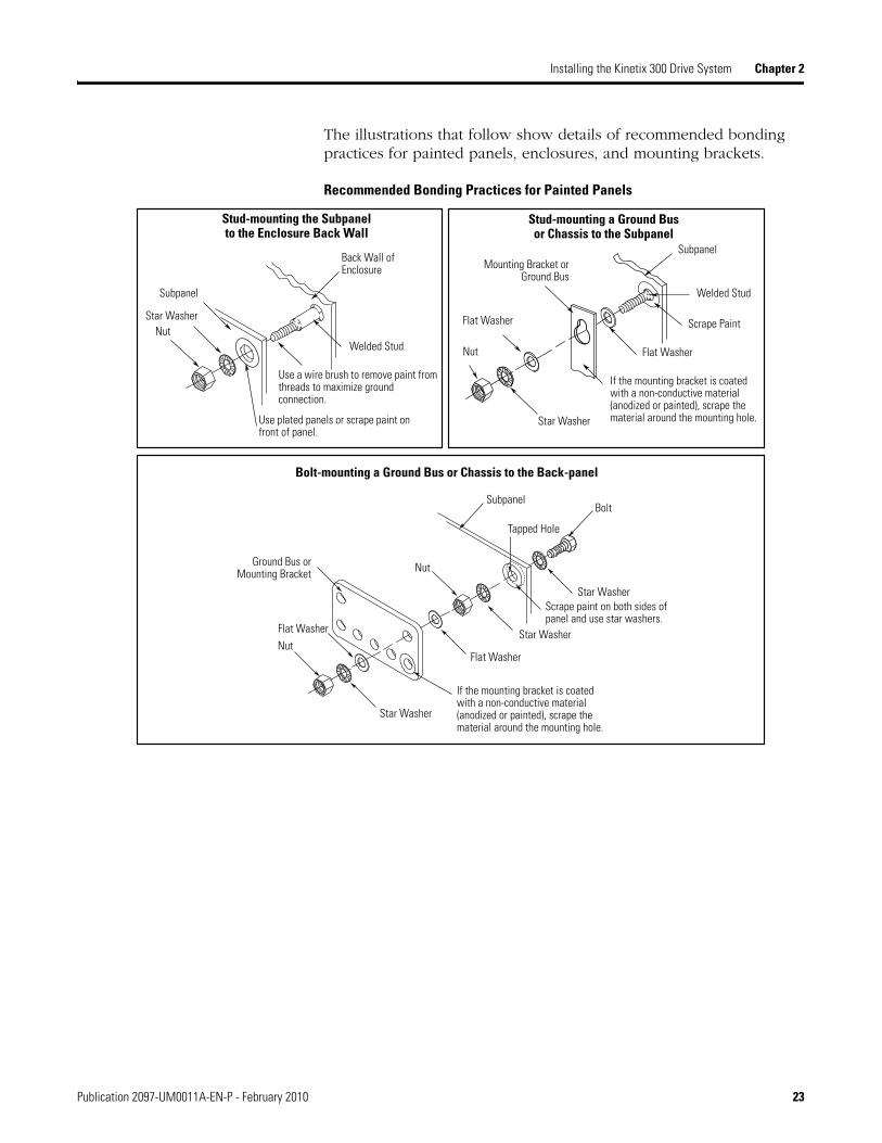
The illustrations that follow show details of recommended bonding practices for painted panels, enclosures, and mounting brackets.
Recommended Bonding Practices for Painted Panels
Stud-mounting the Subpanelto the Enclosure Back Wall
Subpanel
Star WasherNut
Back Wall of Enclosure
Welded Stud
Use a wire brush to remove paint from threads to maximize ground connection.
Use plated panels or scrape paint on front of panel.
Nut
Star Washer
Welded Stud
Flat Washer
Stud-mounting a Ground Busor Chassis to the Subpanel
Scrape Paint
Flat Washer
If the mounting bracket is coated with a non-conductive material (anodized or painted), scrape the material around the mounting hole.
Mounting Bracket orGround Bus
Subpanel
Subpanel
Nut
Nut
Star Washer
Flat Washer
Star Washer
Star WasherScrape paint on both sides of panel and use star washers.
Tapped Hole
Bolt
Flat Washer
Ground Bus or Mounting Bracket
If the mounting bracket is coated with a non-conductive material (anodized or painted), scrape the material around the mounting hole.
Bolt-mounting a Ground Bus or Chassis to the Back-panel
Publication 2097-UM0011A-EN-P - February 2010 23

Chapter 2 Installing the Kinetix 300 Drive System
Bonding Multiple Subpanels
Bonding multiple subpanels creates a common low impedance exit path for the high frequency energy inside the cabinet. Subpanels that are not bonded together may not share a common low impedance path. This difference in impedance may affect networks and other devices that span multiple panels.
Multiple Subpanels and Cabinet Recommendations
Wire Braid.25.4 mm (1.0 in.) by 6.35 mm (0.25 in.)
Remove paint from cabinet.
Ground bus bonded to the
subpanel.
Wire Braid.25.4 mm (1.0 in.) by 6.35 mm (0.25 in.)
24 Publication 2097-UM0011A-EN-P - February 2010

Installing the Kinetix 300 Drive System Chapter 2
Establishing Noise Zones
Observe these guidelines when individual input power components are used in the Kinetix 300 system:
The clean zone (C) exits left of the Kinetix 300 system and includes the I/O wiring, feedback cable, Ethernet cable, and DC filter (grey wireway).
The dirty zone (D) exits right of the Kinetix 300 system (black wireway) and includes the circuit breakers, transformer, 24V DC power supply, contactors, AC line filter, motor power, and safety cables.
The very dirty zone (VD) is limited to where the AC line (EMC) filter VAC output jumpers over to the drive. Shielded cable is required only if the very dirty cables enter a wireway.
Establishing Noise Zones for Installations With Bulletin 2090 AC Line Filter
(1) If drive system I/O cable contains (dirty) relay wires, route cable in dirty wireway.
(2) For tight spaces use a grounded steel shield. For examples, refer to the System Design for Control of Electrical Noise Reference Manual, publication GMC-RM001.
(3) This is a clean 24V DC available for any device that may require it. The 24V enters the clean wireway and exits to the left.
(4) This is a dirty 24V DC available for motor brakes and contactors. The 24V enters the dirty wireway and exits to the right.
Clean Wireway
24V MotorBrake PS
CircuitBreaker
Contactors
Kinetix 300 Drive
I/O (1) and Feedback Cables
Very Dirty ZoneSegregated (not in wireway).
Route 24V DC I/O Shielded Cable
Ethernet (shielded)
Cable
I/O (1), Motor Power, and Safety Cables
(4)
(3)
Dirty Wireway
XRFMDCFilter
OptionalAC Line Filter
2090-XXLF-TC116
Route encoder/analog/registrationshielded cables.
D D
VDVD
D
CC
No sensitive equipment within 150 mm (6.0 in.).(2)
Publication 2097-UM0011A-EN-P - February 2010 25

Chapter 2 Installing the Kinetix 300 Drive System
Establishing Noise Zones for Installations With Bulletin 2097 AC Line Filter
(1) If drive system I/O cable contains (dirty) relay wires, route cable in dirty wireway.
(2) For tight spaces use a grounded steel shield. For examples, refer to the System Design for Control of Electrical Noise Reference Manual, publication GMC-RM001.
(3) This is a clean 24V DC available for any device that may require it. The 24V enters the clean wireway and exits to the left.
(4) This is a dirty 24V DC available for motor brakes and contactors. The 24V enters the dirty wireway and exits to the right.
Clean Wireway
24V MotorBrake PS
CircuitBreaker
Contactors
Kinetix 300 Drive
I/O (1) and Feedback Cables
Very Dirty ZoneSegregated (not in wireway).
Route 24V DC I/O Shielded Cable
Ethernet (shielded)
Cable
I/O (1), Motor Power, and Safety Cables
(4)
(3)
Dirty Wireway
XRFMDCFilter
Route encoder/analog/registrationshielded cables.
D D
VD
VD
D
CC
Bulletin 2097 AC line filter mounts to side, as shown, or behind the drive.
No sensitive equipment within 150 mm (6.0 in.).(2)
26 Publication 2097-UM0011A-EN-P - February 2010

Installing the Kinetix 300 Drive System Chapter 2
Cable Categories for Kinetix 300 Drive Components
These table indicate the zoning requirements of cables connecting to the Kinetix 300 drive components.
Kinetix 300 Drive Components
Noise Reduction Guidelines for Drive Accessories
Refer to this section when mounting an AC line filter or shunt resistor module for guidelines designed to reduce system failures caused by excessive electrical noise.
AC Line Filters
Observe the following guidelines when mounting your AC line filter:
Good HF bonding to the panel is critical. For painted panels, refer to the examples on page 23.
Segregate input and output wiring as far as possible.
Wire/Cable ConnectorZone Method
Very Dirty Dirty Clean Ferrite
SleeveShielded
Cable
L1, L2, L3 (unshielded cable) IPD X
U, V, W (motor power) MP X X
B+-, B-, BR (shunt resistor) BC X
24V DC BP X
Control COM, 24V DC control, safety enable, and feedback signals for safe-off feature
STO X
Motor feedback MF X X
Registration and analog outputsIOD
X X
Others X
Ethernet Port 1 X X
Publication 2097-UM0011A-EN-P - February 2010 27

Chapter 2 Installing the Kinetix 300 Drive System
Shunt Resistors
Observe these guidelines when mounting your shunt resistor outside the enclosure:
Mount shunt resistor and wiring in the very dirty zone or in an external shielded enclosure.
Mount resistors in a shielded and ventilated enclosure outside the cabinet.
Keep unshielded wiring as short as possible. Keep shunt wiring as flat to the cabinet as possible.
Shunt Resistor Outside the Enclosure
(1) If drive system I/O cable contains (dirty) relay wires, route cable in dirty wire way.
(2) When space does not permit the 150 mm (6.0 in.) segregation, use a grounded steel shield instead. for examples, refer to the System Design for Control of Electrical Noise Reference Manual, publication GMC-RM001.
Contactor
Dirty Wireway
Customer-suppliedMetal Enclosure
150 mm (6.0 in.) clearance (min) on all four sides of the shunt module.
Very dirty connectionssegregated (not in wireway).
Shunt Wiring Methods:Twisted pair in conduit (first choice).Shielded twisted pair (second choice).Twisted pair, two twists per foot (min) (third choice).
Metal Conduit(where requiredby local code)
Ethernet (shielded)
Cable
No sensitive equipment within 150 mm (6.0 in.).(2)
Route 24V DC I/O Shielded Cable
24V Motor Brake PS
EnclosureClean Wireway
CircuitBreaker
I/O (1) and Feedback Cables
DCFilter
Kinetix 300 Drive
Route Encoder/Analog/RegistrationShielded Cables
D
VD
D
CC
I/O (1), Motor Power and Safety Cables
XFMR
D
AC Line Filter
VD
28 Publication 2097-UM0011A-EN-P - February 2010

Installing the Kinetix 300 Drive System Chapter 2
When mounting your shunt module inside the enclosure, follow these additional guidelines:
Mount the shunt resistor anywhere in the dirty zone, but as close to the Kinetix 300 drive as possible.
Shunt wires can be run with motor power cables.
Keep unshielded wiring as short as possible. Keep shunt wiring as flat to the cabinet as possible.
Separate shunt wires from other sensitive, low voltage signal cables.
Shunt Resistor Inside the Enclosure
(1) If drive system I/O cable contains (dirty) relay wires, route cable in dirty wire way.
(2) When space does not permit the 150 mm (6.0 in.) segregation, use a grounded steel shield instead. for examples, refer to the System Design for Control of Electrical Noise Reference Manual, publication GMC-RM001.
Shunt Wiring Methods:Twisted pair in conduit (first choice).Shielded twisted pair (second choice).Twisted pair, two twists per foot (min) (third choice).
Contactor
Dirty Wireway
Very dirty zonesegregated (not in wireway).
Ethernet (shielded)
Cable
No sensitive equipment within 150 mm (6.0 in.).(2)
Route 24V DC I/O Shielded Cable
24V Motor Brake PS
CircuitBreaker
I/O (1) and Feedback Cables
DCFilter
Kinetix 300 Drive
Route Encoder/Analog/RegistrationShielded Cables
D
VD
C
I/O (1), Motor Power and Safety Cables
XFMR
D D
AC Line Filter
VD
D
C
Publication 2097-UM0011A-EN-P - February 2010 29

Chapter 2 Installing the Kinetix 300 Drive System
Motor Brake
The brake is mounted inside the motor, how you connect to the axis module depends on the motor series.
Refer to Kinetix 300 Drive/Rotary Motor Wiring Examples beginning on page 141 for the interconnect diagram of your drive/motor combination.
Mounting Your Kinetix 300 Drive
The procedures in this section assume you have prepared your panel and understand how to bond your system. For installation instructions regarding other equipment and accessories, refer to the instructions that came with each of the accessories for their specific requirements.
Follow these steps to mount your Kinetix 300 drive.
1. Layout the position for the Kinetix 300 and accessories in the enclosure (refer to Establishing Noise Zones for panel layout recommendations).
Mounting hole dimensions for the Kinetix 300 are shown in Appendix A.
2. Attach the Kinetix 300 drive to the cabinet, first using the upper mounting slots of the drive and then the lower.
The recommended mounting hardware is M4 (#6-32) steel machine screw torqued to 1.1 N•m (9.8 lb•in). Observe bonding techniques as described in Bonding Drives.
3. Tighten all mounting fasteners.
ATTENTION This drive contains electrostatic discharge (ESD) sensitive parts and assemblies. You are required to follow static control precautions when you install, test, service, or repair this assembly. If you do not follow ESD control procedures, components can be damaged. If you are not familiar with static control procedures, refer to Allen-Bradley publication 8000-4.5.2, Guarding Against Electrostatic Damage or any other applicable ESD Protection Handbook.
IMPORTANT To improve the bond between the Kinetix 300 drive and subpanel, construct your subpanel out of zinc plated (paint-free) steel.
30 Publication 2097-UM0011A-EN-P - February 2010

Chapter 3
Kinetix 300 Drive Connector Data
Introduction This chapter provides power, feedback, and I/O connector locations and signal descriptions for your Kinetix 300 drive.
Topic Page
Introduction 31
Kinetix 300 Drive Connectors and Indicators 32
Understanding Motor Feedback Specifications 38
Understanding Control Signal Specifications 44
31Publication 2097-UM001A-EN-P - February 2010 31

Chapter 3 Kinetix 300 Drive Connector Data
Kinetix 300 Drive Connectors and Indicators
Although the physical size of the 460V modules is larger than the 230V modules, the location of the connectors and indicators is identical.
Kinetix 300 Drive Connector and Indicators
Item Description Item Description
1 Ground lug 9 Ethernet communication port (Port 1)
2 Status and diagnostic display 10 Memory module
3 Display control push buttons (3) 11 Top mounting flange
4 Back-up power (BP) connector 12 Mains (IPD) connector
5 Shunt resistor and DC bus (BC) connector 13 Motor power (MP) connector
6 Bottom mounting flange 14 Safe torque off (STO) connector
7 Motor feedback (MF) connector 15 Heat sink (on some models)
8 I/O (IOD) connector
11
9
8
5
2
4
7
3
12
15
13
14
16
Top View(2097-V33PR5 Kinetix 300 drive is shown)
Bottom View(2097-V33PR5 Kinetix 300 drive is shown)
Front Panel View(2097-V33PR5 Kinetix 300 drive is shown)
10
1
32 Publication 2097-UM001A-EN-P - February 2010
Kinetix 300 Drive Connector Data Chapter 3
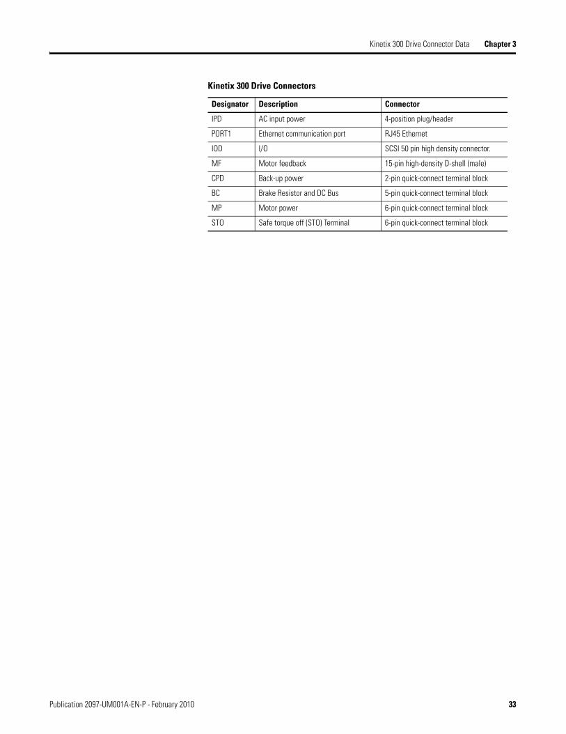
Kinetix 300 Drive Connectors
Designator Description Connector
IPD AC input power 4-position plug/header
PORT1 Ethernet communication port RJ45 Ethernet
IOD I/O SCSI 50 pin high density connector.
MF Motor feedback 15-pin high-density D-shell (male)
CPD Back-up power 2-pin quick-connect terminal block
BC Brake Resistor and DC Bus 5-pin quick-connect terminal block
MP Motor power 6-pin quick-connect terminal block
STO Safe torque off (STO) Terminal 6-pin quick-connect terminal block
Publication 2097-UM001A-EN-P - February 2010 33

Chapter 3 Kinetix 300 Drive Connector Data
Safe Torque-off Pinout
The Kinetix 300 drive ships with the (6-pin) wiring-plug header that connects to your safety circuit to the Kinetix 300 drive safe torque-off (STO) connector. If your system does not use the safe torque-off feature, follow instructions in Appendix D starting on page 155 to wire the drive with motion allow jumpers.
Safe Torque-off Connector
Kinetix 300 Drive Safe Torque-off (STO) Connector
STO Pin Description Signal
1 +24V DC output from the drive +24V DC control
2 +24V DC output common Control COM
3 Safety status Safety Status
4 Safety input 1 (+24V DC to enable) Safety Input 1
5 Safety common Safety COM
6 Safety input 2 (+24V DC to enable) Safety Input 2
IMPORTANT Pins STO-1 (+24V DC Control) and STO-2 (Control COM) are used only by the motion-allowed jumpers to defeat the safe torque-off function. When the safe torque off function is in operation, the 24V supply must come from an external source.
1 2 3 4 5 6 +24 V DC control
Control COM
Safety status
Safety input 1
Safety COM
Safety input 2
Bottom view of the Kinetix 300 drive. (2097-V33PR5 drive is shown)
Wiring Plug Header
Safe Torque-off (STO) Connector
34 Publication 2097-UM001A-EN-P - February 2010

Kinetix 300 Drive Connector Data Chapter 3
I/O (IOD) Connector Pinout
Pin Orientation for 50-pin SCSI I/O (IOD) Connector
IOD Pin Description Signal IOD Pin Description Signal
1 Master encoder A+/Step+ input MA+ 30 Digital input A4 IN_A4
2 Master encoder A-/Step- input MA- 31 Digital input group BCOM terminal IN_B_COM
3 Master encoder B+/Direction+ input MB+ 32 Digital input B1 IN_B1
4 Master encoder B-/Direction- input MB- 33 Digital input B2 IN_B2
5 Drive logic common GND 34 Digital input B3 IN_B3
6 +5V DC Output (max 100 mA) 5V DC 35 Digital input B4 IN_B4
7 Buffered encoder output: channel A+ BA+ 36 Digital input Group CCOM Terminal IN_C_COM
8 Buffered encoder output: channel A- BA- 37 Digital input C1 IN_C1
9 Buffered encoder output: channel B+ BB+ 38 Digital input C2 IN_C2
10 Buffered encoder output: channel B- BB- 39 Digital input C3 IN_C3
11 Buffered encoder output: channel Z+ BZ+ 40 Digital input C4 IN_C4
12 Buffered encoder output: channel Z- BZ- 41 Ready output collector RDY+
13…21 Reserved — 42 Ready output emitter RDY-
22 Analog common ACOM 43 Programmable output #1 collector OUT1-C
23 Analog output (max 10 mA) AO 44 Programmable output #1 emitter OUT1-E
24 Positive (+) of analog signal input AIN1+ 45 Programmable output #2 collector OUT2-C
25 Negative (-) of analog signal input AIN1- 46 Programmable output #2 emitter OUT2-E
26 Digital input group ACOM terminal IN_A_COM 47 Programmable output #3 collector OUT3-C
27 Digital input A1 IN_A1 48 Programmable output #3 emitter OUT3-E
28 Digital input A2 IN_A2 49 Programmable output #4 collector OUT4-C
29 Digital input A3 IN_A3 50 Programmable output #4 emitter OUT4-E
1
25 50
26
Publication 2097-UM001A-EN-P - February 2010 35

Chapter 3 Kinetix 300 Drive Connector Data
Motor Feedback (MF) Connector Pinout
Pin Orientation for 15-pin Motor Feedback (MF) Connector
Pin Orientation for 8-pin Ethernet Communication Port (port 1)
MF Pin Description Signal MF Pin Description Signal
1 Sine differential input+AM+ differential input+
SIN+AM+
9 Reserved —
2 Sine differential input-AM- differential input-
SIN-AM-
10 Data differential input -Index pulse-
DATA-IM-
3 Cosine differential input+BM+ differential input+
COS+BM+
11 Motor thermal switch (normally closed) (1)
TS
4 Cosine differential input-BM- differential input-
COS-BM-
12 Single-ended 5V Hall effect commutation
S1
5 Data differential input +Index pulse+
DATA+IM+
13 Single-ended 5V Hall effect commutation
S2
6 Common ECOM 14 Encoder power (+5V) EPWR_5V (2)
7 Encoder power (+9V) EPWR_9V (2) 15 Reserved —
8 Single-ended 5V Hall effect commutation
S3
(1) Not applicable unless motor has integrated thermal protection.(2) Encoder power supply uses either 5V or 9V DC based on encoder/motor used.
Ethernet Communication Port (port 1)
Port 1 Pin Signal Description
1 + TX Transmit Port (+) Data Terminal
2 - TX Transmit Port (-) Data Terminal
3 + RX Receive Port (+) Data Terminal
4 — —
5 — —
6 - RX Receive Port (-) Data Terminal
7 — —
8 — —
Pin 11Pin 6
Pin 15
Pin 1
Pin 10Pin 5
1
8
36 Publication 2097-UM001A-EN-P - February 2010

Kinetix 300 Drive Connector Data Chapter 3
AC Input Power (IPD) Connector
Back-up Power Pinout
Back-up Power (BP) Connector
Shunt Resistor and DC Bus Pinout
Shunt Resistor and DC Bus (BC) Connector
Motor Power Pinout
Motor Power (MP) Connector
IPD Pin Description Signal
1 Protective Earth (ground) PE
2 AC Power In L1
3 AC Power In L2
4 AC Power In (3 phase models) L3
BP Pin Description Signal
1 Positive 24V DC +24V DC
2 24V DC power supply return Return
BC Pin Description Signal
1…2 Positive DC bus/brake resistor B+
3 Brake Resistor BR
4…5 Negative DC bus B-
MP Pin Description Signal
1…2 Reserved —
3 Motor power out U
4 Motor power out V
5 Motor power out W
6 Protective Earth (ground) PE
Publication 2097-UM001A-EN-P - February 2010 37

Chapter 3 Kinetix 300 Drive Connector Data
Understanding Motor Feedback Specifications
The Kinetix 300 drive accepts motor feedback signals from the following types of encoders with these general specifications.
Motor Feedback General Specifications
Attribute Motor Feedback
Feedback device support Stegmann Hiperface
Generic TTL Incremental
Tamagawa 17-bit Serial
Power supply voltage (EPWR5V) 5.13…5.67V
Power supply current (EPWR5V) 400 mA, max (1) (2)
(1) 400 mA on the 5V supply with no load on the 9V supply.(2) 300 mA on the 5V supply with 150 mA on the 9V supply.
Power supply voltage (EPWR9V) 8.3…9.9V
Power supply current (EPWR9V) 275 mA, max (2)(3)
(3) 275 mA on the 9V supply with no load on the 5V supply.
Thermostat Single-ended, under 500 = no fault, over 10 k= fault
TIP Auto-configuration is possible using the Kinetix 300 drive MotionView OnBoard software for Allen-Bradley motors.
38 Publication 2097-UM001A-EN-P - February 2010

Kinetix 300 Drive Connector Data Chapter 3
Motor Feedback Specifications
The Kinetix 300 drives support multiple types of feedback devices using the 15-pin (MF) motor feedback connector and sharing connector pins in many cases.
Motor Feedback Signals by Device Type
This is the motor thermostat interface schematic. Although the thermostat signal is shown for all feedback types, some motors may not support this feature since it is not part of the feedback device.
Motor Thermostat Interface
MF Pin Stegmann Hiperface Generic TTL Incremental
Tamagawa 17-bit Serial
1 SIN+ AM+ —
2 SIN- AM- —
3 COS+ BM+ —
4 COS- BM- —
5 DATA+ IM+ DATA+
6 ECOM ECOM ECOM
7 EPWR9V — —
8 — S3 —
9 — — —
10 DATA- IM- DATA-
11 TS TS—
12 — S1 —
13 — S2 —
14 — EPWR5V EPWR5V
15 — — —
+5V
1 kΩ
6.81 kΩ
0.01 µF
MTR_TS
+5V
Kinetix 300 Drive
Motor Thermostat State
State Resistance at TS
No Fault 500
Fault 10 k
Publication 2097-UM001A-EN-P - February 2010 39
Chapter 3 Kinetix 300 Drive Connector Data
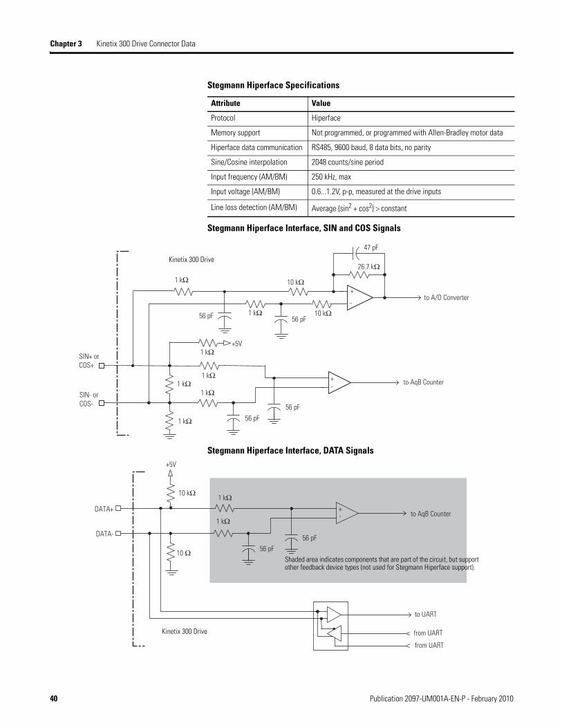
Stegmann Hiperface Specifications
Stegmann Hiperface Interface, SIN and COS Signals
Stegmann Hiperface Interface, DATA Signals
Attribute Value
Protocol Hiperface
Memory support Not programmed, or programmed with Allen-Bradley motor data
Hiperface data communication RS485, 9600 baud, 8 data bits, no parity
Sine/Cosine interpolation 2048 counts/sine period
Input frequency (AM/BM) 250 kHz, max
Input voltage (AM/BM) 0.6...1.2V, p-p, measured at the drive inputs
Line loss detection (AM/BM) Average (sin2 + cos2) > constant
56 pF
SIN+ orCOS+
SIN- orCOS-
+1 kΩ
-
to AqB Counter
1 kΩ 10 kΩ
10 kΩ1 kΩ
1 kΩ1 kΩ
56 pF
56 pF
26.7 kΩ
47 pF
to A/D Converter
56 pF
+5V
1 kΩ
+
-
1 kΩ
Kinetix 300 Drive
+
to UART
from UART
from UART
DATA+
DATA-
10 kΩ
to AqB Counter
1 kΩ
1 kΩ
10 Ω
56 pF56 pF
+5V
-
Kinetix 300 Drive
Shaded area indicates components that are part of the circuit, but support other feedback device types (not used for Stegmann Hiperface support).
40 Publication 2097-UM001A-EN-P - February 2010

Kinetix 300 Drive Connector Data Chapter 3
Generic TTL Incremental Specifications
Generic TTL Incremental, AM and BM Signals
Attribute Value
TTL incremental encoder support 5V, differential A quad B
Quadrature interpolation 4 counts/square wave period
Differential input voltage (AM, BM, and IM) 1.0…7.0V
DC current draw (AM, BM, and IM) 30 mA, max
Input signal frequency (AM, BM, and IM) 5.0 MHz, max
Edge separation (AM and BM) 42 ns min, between any two edges
Line loss detection (AM and BM) Average (AM2 + BM2) > constant
Hall inputs (S1, S2, and S3) Single-ended, TTL, open collector, or none
AM- orBM-
1 kΩ
to A/D Converter
56 pF56 pF
1 kΩ
1K Ω
AM+ orBM+
1 kΩ
10 kΩ
56 pF
47 pF
26.7 kΩ
+
+
to AqB Counter
1 kΩ
10 kΩ
56 pF
-
-
Kinetix 300 Drive
Shaded area indicates components that are part of the circuit, but support other feedback device types (not used for Generic TTL incremental support).
Publication 2097-UM001A-EN-P - February 2010 41
Chapter 3 Kinetix 300 Drive Connector Data
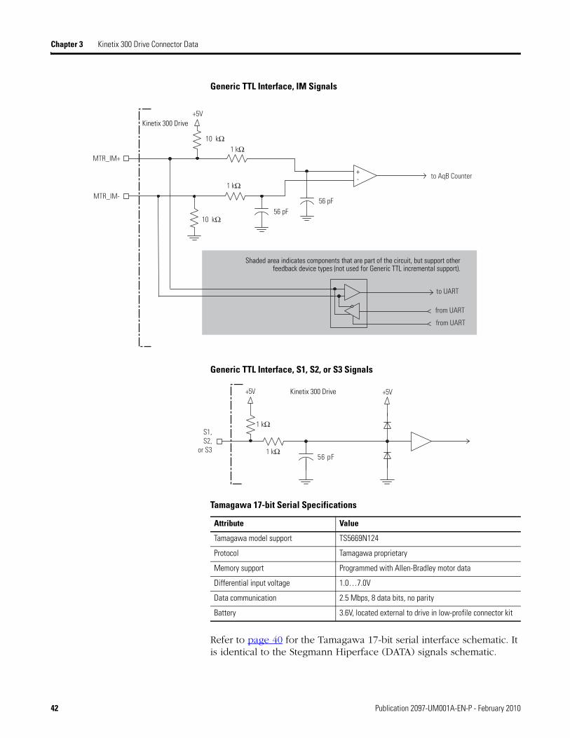
Generic TTL Interface, IM Signals
Generic TTL Interface, S1, S2, or S3 Signals
Tamagawa 17-bit Serial Specifications
Refer to page 40 for the Tamagawa 17-bit serial interface schematic. It is identical to the Stegmann Hiperface (DATA) signals schematic.
+
to UART
from UART
from UART
MTR_IM-
56 pF
MTR_IM+
10 kΩ
to AqB Counter
10 kΩ
1 kΩ
1 kΩ
56 pF
+5V
-
Kinetix 300 Drive
Shaded area indicates components that are part of the circuit, but support other feedback device types (not used for Generic TTL incremental support).
1 kΩ
S1,S2,
or S3
+5V
56 pF
1 kΩ
+5VKinetix 300 Drive
Attribute Value
Tamagawa model support TS5669N124
Protocol Tamagawa proprietary
Memory support Programmed with Allen-Bradley motor data
Differential input voltage 1.0…7.0V
Data communication 2.5 Mbps, 8 data bits, no parity
Battery 3.6V, located external to drive in low-profile connector kit
42 Publication 2097-UM001A-EN-P - February 2010

Kinetix 300 Drive Connector Data Chapter 3
Feedback Power Supply
The Kinetix 300 drive generates +5V and +9V DC for motor feedback power. Short circuit protection and separate common mode filtering for each channel is included.
Motor Feedback Power Specifications
Pin Orientation for 15-pin Motor Feedback (MF) Connector
Supply ReferenceVoltage Current mA
Min Nominal Max Min Max
+5V DC EPWR_5V 5.13 5.4 5.67 0 400
+9V DC EPWR_9V 8.3 9.1 9.9 0 275
Pin 11Pin 6
Pin 15
Pin 1
Pin 10Pin 5
Publication 2097-UM001A-EN-P - February 2010 43

Chapter 3 Kinetix 300 Drive Connector Data
Understanding Control Signal Specifications
This section provides a description of the Kinetix 300 drive I/O (IOD), communication, shunt resistor and DC bus (DC), and backup power (BP) connectors.
Digital Inputs
The Kinetix 300 drive has twelve digital inputs. They can be used for travel limit switches, proximity sensors, push buttons and hand shaking with other devices. Each input can be assigned an individual de-bounce time via MotionView or Explicit Message.
The inputs are separated into three groups: A, B, and C. Each group has four inputs and share one common: ACOM, BCOM, and CCOM respectfully. The inputs are labeled individually as IN_A1…IN_A4, IN_B1…IN_B4, and IN_C1…IN_C4.
Travel limit switches, inhibit/enable input, homing, and registration input can be used only on specific digital inputs as shown in table.
Input A3 can be used only for inhibit/enable input function.
Digital Input Assignments
Digital Input Function
Input A1 Negative travel limit switch
Input A2 Positive travel limit switch
Input A3 Inhibit/enable input
Input A4 N/A
Input B1 N/A
Input B2 N/A
Input B3 N/A
Input B4 N/A
Input C1 N/A
Input C2 N/A
Input C3 N/A
Input C3 Homing and registration input sensor
Input C4 N/A
44 Publication 2097-UM001A-EN-P - February 2010

Kinetix 300 Drive Connector Data Chapter 3
The digital inputs explicitly shown in Digital Input Assignments table are fixed functions, those inputs can be used only for those functions and those functions can be used only on those inputs. The inputs listed as N/A are configurable to be any of the following inputs:
Abort Homing
Abort Index
Start Homing
Start Index
Fault Reset
Home Sensor
Some of the digital inputs exercise control over functions also under the control of the Output Assembly. In the case of a digital input being mapped to the same function as exists in the Output Assembly the following truth tables applies.
Enable Truth Table (configured for Run)
Drive Input Value
Enable Input Off Move to On On On
Drive Enable bit in Output Assembly(1)
(1) Only applicable if EtherNet/IP External Reference mode.
– On Move to Off
Move to On
Resulting Drive State Disabled Enabled Disabled Enabled
Enable Input (configured for Inhibit)
Drive Input Value
Enable Input On On Off
Drive Enable bit in Output Assembly
Move to On
Move to Off –
Resulting Drive State Enabled Disabled Disabled
Publication 2097-UM001A-EN-P - February 2010 45

Chapter 3 Kinetix 300 Drive Connector Data
The digital inputs are optically isolated and sinks up to 24V DC. Electrical details are shown in Digital Input Signal Specifications. The inputs can be setup for PNP sourcing or NPN sinking.
Homing Truth Table
Drive Input Value
Start Homing Input — — Move to On — — —
Start Homing bit in Output Assembly — — — Move to
On — —
Abort Homing Input On — Off Off Move to On —
Abort Homing bit in Output Assembly — On Off Off — Move to
On
Previous Drive State Enabled Enabled Enabled Enabled Homing Homing
Resulting Drive State Will not home
Will not home
Starts homing
Starts homing
Aborts homing
Aborts homing
Indexing Truth Table
Drive Input Value
Start Index Input — — Move to On — — —
Start Motion bit in Output Assembly — — — Move to
On — —
Abort Index Input On — Off Off Move to On —
Abort Index bit in Output Assembly — On Off Off — Move to
On
Previous Drive State Enabled Enabled Enabled Enabled Indexing Indexing
Resulting Drive State Will not index
Will not index
Starts indexing
Starts indexing
Aborts indexing
Aborts Indexing
46 Publication 2097-UM001A-EN-P - February 2010

Kinetix 300 Drive Connector Data Chapter 3
Sourcing of Digital Inputs
Sinking of Digital Inputs
Digital Input Signal Specifications
Parameter Value
Scan time 500 µs
Current, max 9 mA, typical
Input impedance 1.2 k, typical
Voltage range 10…24V DC
GND
IN_A2
IN_A_COM
+24V
IN_A1
1.2 k
1.2 k
GND
IN_A2
IN_A_COM+24V
IN_A1
1.2 k
1.2 k
Publication 2097-UM001A-EN-P - February 2010 47
Chapter 3 Kinetix 300 Drive Connector Data
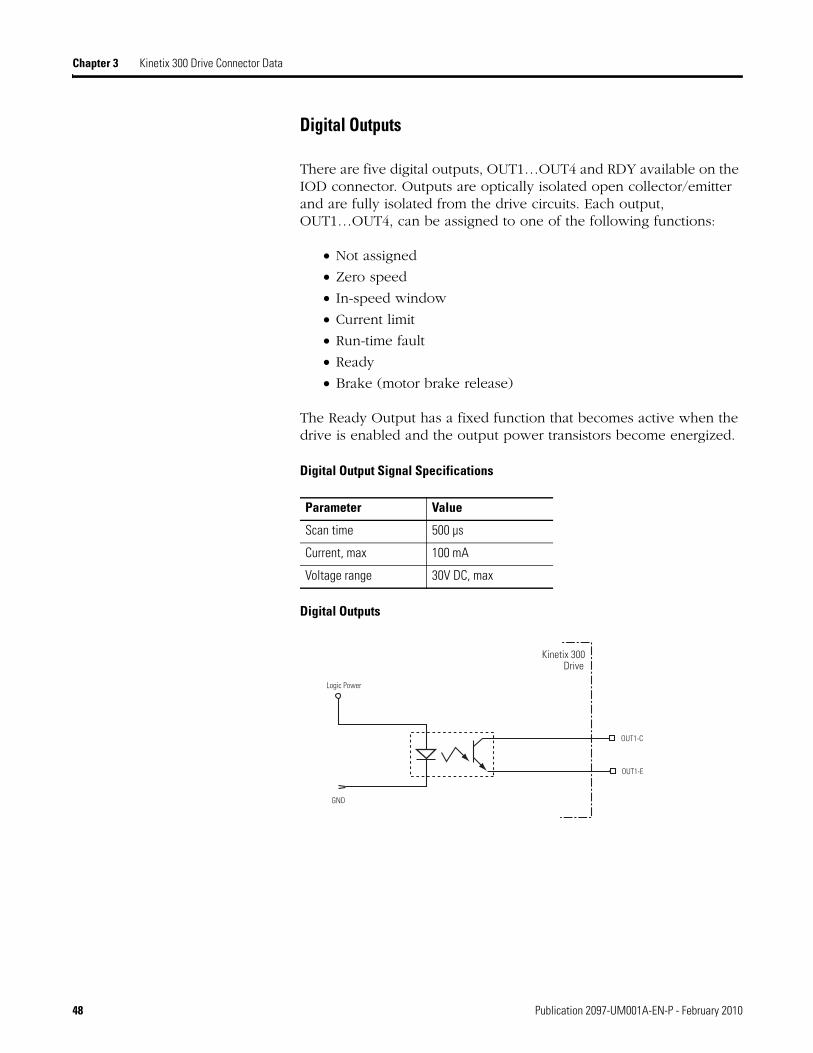
Digital Outputs
There are five digital outputs, OUT1…OUT4 and RDY available on the IOD connector. Outputs are optically isolated open collector/emitter and are fully isolated from the drive circuits. Each output, OUT1…OUT4, can be assigned to one of the following functions:
Not assigned
Zero speed
In-speed window
Current limit
Run-time fault
Ready
Brake (motor brake release)
The Ready Output has a fixed function that becomes active when the drive is enabled and the output power transistors become energized.
Digital Output Signal Specifications
Digital Outputs
Parameter Value
Scan time 500 µs
Current, max 100 mA
Voltage range 30V DC, max
OUT1-E
OUT1-C
Logic Power
GND
Kinetix 300 Drive
48 Publication 2097-UM001A-EN-P - February 2010

Kinetix 300 Drive Connector Data Chapter 3
Analog Reference Input
The analog reference input AIN1+ and AIN1- (IOD-24 and IOD-25) accepts up to a ±10V DC analog signal across AIN1+ and AIN1-, with electrical details shown Analog Signal Input Specifications table on page 49. The analog signal is converted to a digital value with 12 bit resolution (11 bit plus sign). The total reference voltage as seen by the drive is the voltage difference between AIN1+ and AIN1-. If used in Single-ended mode, one of the inputs must be connected to a voltage source while the other one must be connected to Analog Common (ACOM). If used in Differential mode, the voltage source is connected across AIN1+ and AIN1- and the driving circuit common, if available, is connected to the drive Analog Common (ACOM) terminal.
Analog Signal Input Specifications
Analog Output
The analog output (AO) on pin IOD-23 has a 10 bit resolution with electrical details shown Analog Output Specifications table on page 50. The analog output is a single-ended signal with reference to Analog Common (ACOM) which can represent the following motor data:
Not Assigned
RMS Phase Current
RMS Peak Current
Motor Velocity
Phase Current R
Phase Current S
Phase Current T
Iq Current
Id Current
Parameter Value
Scan time 0.0625 ms
Current, max Depend on load
Input impedance 47 k, typical
Voltage range -10…10V DC
IMPORTANT Output values can vary during powerup until the specified power supply voltage is reached.
Publication 2097-UM001A-EN-P - February 2010 49

Chapter 3 Kinetix 300 Drive Connector Data
Analog Output Circuit
Analog Output Specifications
For configuration/setup of the analog outputs, refer to Configure Drive Parameters and System Variables beginning on page 108.
Ethernet Connection
An RJ45 Ethernet connector (port 1) is provided on the Kinetix 300 drive.
Ethernet Communication Specifications
Parameter Value
Scan time 0.0625 ms
Current, max 10 mA
Voltage range -10…10V DC
Attribute Value
Communications 100BASE-TX, full duplex
Cyclic update period 2 ms, min
Auto MDI/MDIX crossover detection/correction Yes
Cabling CAT5E or CAT6, unshielded or shielded, 100 m (328 ft)
CH1 CH2
DAC
50 Publication 2097-UM001A-EN-P - February 2010

Kinetix 300 Drive Connector Data Chapter 3
24V DC Back-Up Power
The Kinetix 300 drive can use an external power supply to power the logic and communication circuit. During a mains input power loss, the logic and communication remains active if an independent 24V power supply is connected to the BP connector.
24V DC Back-Up Power
Attribute Value
Input voltage 20…26V DC
Current 500 mA
Inrush, max 30 A
Publication 2097-UM001A-EN-P - February 2010 51

Chapter 3 Kinetix 300 Drive Connector Data
Notes:
52 Publication 2097-UM001A-EN-P - February 2010

Chapter 4
Connecting the Kinetix 300 Drive System
Introduction This chapter provides procedures for wiring your Kinetix 300 system components and making cable connections.
Understanding Basic Wiring Requirements
This section contains basic wiring information for the Kinetix 300 drive.
Topic Page
Introduction 53
Understanding Basic Wiring Requirements 53
Grounding Your Kinetix 300 Drive 61
Power Wiring Requirements 63
Wiring Guidelines 65
Wiring the Kinetix 300 Drive Connectors 66
Apply the Motor Cable Shield Clamp 74
Understanding Feedback and I/O Cable Connections 75
Wiring I/O Connector 77
Wiring Feedback Connector 78
Understanding Shunt Resistor Connections 79
Connecting Your Ethernet Cables 80
ATTENTION Plan the installation of your system so that you can perform all cutting, drilling, tapping, and welding with the system removed from the enclosure. Because the system is of the open type construction, be careful to keep any metal debris from falling into it. Metal debris or other foreign matter can become lodged in the circuitry, which can result in damage to components.
SHOCK HAZARD To avoid hazard of electrical shock, perform all mounting and wiring of the Bulletin 2097 drive prior to applying power. Once power is applied, connector terminals may have voltage present even when not in use.
53Publication 2097-UM001A-EN-P - February 2010 53
Chapter 4 Connecting the Kinetix 300 Drive System
Building Your Own Cables
Connect the cable shield to the connector shells on both ends of the cable with a complete 360° connection.
Use twisted pair cable whenever possible. Twist differential signals with each other and twist single-ended signals with the appropriate ground return.
Refer to the Kinetix Motion Control Selection Guide, publication GMC-SG001, for low-profile connector kit, drive-end (mating) connector kit, and motor-end connector kit catalog numbers.
Routing Power and Signal Wiring
Be aware that when you route power and signal wiring on a machine or system, radiated noise from nearby relays, transformers, and other electronic drives can be induced into motor or encoder feedback signals, input/output communication, or other sensitive low voltage signals. This can cause system faults and communication anomalies.
Refer to Minimizing Electrical Noise on page 22 for examples of routing high and low voltage cables in wireways. Refer to the System Design for Control of Electrical Noise Reference Manual, publication GMC-RM001, for more information.
IMPORTANT This section contains common PWM servo system wiring configurations, size, and practices that can be used in a majority of applications. National Electrical Code, local electrical codes, special operating temperatures, duty cycles, or system configurations take precedence over the values and methods provided.
IMPORTANT Factory-made cables are designed to minimize EMI and are recommended over hand-built cables to optimize system performance.
54 Publication 2097-UM001A-EN-P - February 2010

Connecting the Kinetix 300 Drive System Chapter 4
Determining Your Type of Input Power
On the following pages are examples of typical single-phase and three-phase facility input power wired to single-phase and three-phase Kinetix 300 drives.
The grounded power configuration allows you to ground your single-phase or three-phase power at a neutral point. Match your secondary to one of the examples and be certain to include the grounded neutral connection.
Three-phase Power Wired to Three-phase Drives
The following examples illustrate grounded three-phase power wired to three-phase Kinetix 300 drives when phase-to-phase voltage is within drive specifications.
Three-phase Power Configuration (WYE Secondary)
Feeder and branch short circuit protection is not illustrated.
L1
L2
L3
IPDL1
L2
L3
E
L1
L2
L3
L1
L2
L3
Bonded Cabinet Ground Bus
Transformer (WYE) Secondary
Kinetix 300 DriveThree-phase AC InputIPD Terminals
Ground Grid orPower Distribution Ground
AC LineFilter
Bonded Cabinet Ground Bus
Ground Grid or Power Distribution Ground
Publication 2097-UM001A-EN-P - February 2010 55

Chapter 4 Connecting the Kinetix 300 Drive System
Three-phase Power Configuration (preferred Delta secondary)
Feeder and branch short circuit protection is not illustrated.
Three-phase Power Configuration (tolerated Delta secondary)
Feeder and branch short circuit protection is not illustrated.
IMPORTANT The next two configurations are for 230V AC installations only. They are not recommended for 400/480V AC installation.
L1
L2
L3
IPDL1
L2
L3
E
L1
L2
L3
L1
L2
L3
Transformer (Delta) Secondary
Ground Grid orPower Distribution Ground
Kinetix 300 DriveThree-phase AC InputIPD Terminals
Bonded Cabinet Ground Bus
AC LineFilter
L1
L2
L3
IPDL1
L2
L3
E
L1
L2
L3
L1
L2
L3
Transformer (Delta) Secondary
Ground Grid orPower Distribution Ground
Kinetix 300 DriveThree-phase AC InputIPD Terminals
Bonded Cabinet Ground Bus
AC LineFilter
56 Publication 2097-UM001A-EN-P - February 2010

Connecting the Kinetix 300 Drive System Chapter 4
Single-phase Power Wired to Single-phase Drives
The following examples illustrate grounded single-phase power wired to single-phase Kinetix 300 drives when phase-to-phase voltage is within drive specifications.
Single-phase Grounded Power Configurations
Reducing transformer output reduces motor speed. Feeder and branch short circuit protection is not illustrated.
L1
L2
L1
L2 (Neutral)
IDPL1
L2/N
L1
L2/N
L1
L2/N
E
IPDL1
L2
L1
L2
L1
L2/N
E
Transformer Secondary
Transformer Secondary
Bonded Cabinet Ground Bus
Ground Grid orPower Distribution Ground
AC LineFilter
AC LineFilter115V AC
Output
230V ACOutput
Bonded Cabinet Ground Bus
Ground Grid orPower Distribution Ground
Kinetix 300 Drive Single-phase IDP Terminals
Kinetix 300 Drive Single-phase IDP Terminals
Publication 2097-UM001A-EN-P - February 2010 57

Chapter 4 Connecting the Kinetix 300 Drive System
Isolation Transformer in Grounded Power Configurations
When using an isolation transformer, attach a chassis ground wire to the neutral connection. This accomplishes the following:
Prevents the system from floating and thereby avoids any high voltages that might otherwise occur, for example due to static electricity.
Provides a solid earth path for fault conditions.
Three-phase Power Wired to Single-phase Drives
The following example illustrate grounded three-phase power wired to single-phase Kinetix 300 drives when phase-to-phase voltage is within drive specifications.
Single-phase Amplifiers on Three-phase Power (WYE)
1 AC line filter is optional, but is required for CE compliance.
2 Contactors (MI, M2, and M3) may be optional. For more information, refer to Understanding the Machinery Directive, publication SHB-900.
Feeder short circuit protection is not illustrated.
ATTENTION If the supply transformer is an auto transformer (not recommended), a chassis earth ground should not be added.
A chassis earth ground should already be included elsewhere in the system, and adding another would create a short.
L1
L2
L3
IDPL2/N
IDPL2/N
IPDL1
L2/N
L1
L2
L3L2
L3
L1
L1
L2
L1
L2E
L1
L2
L1
L2E
L1
L2
L1
L2E
Bonded Cabinet Ground Bus
Transformer(WYE) Secondary
Input Fusing
Grounded Neutral
Kinetic 300 Drive (System A)Single-phase AC InputIDP Terminals
Input Fusing
Input FusingM1 2
M2 2
M3 2
Ground Grid orPower Distribution Ground
Bonded Cabinet Ground Bus
Ground Grid orPower Distribution Ground
AC Line Filter
Kinetic 300 Drive (System B)Single-phase AC InputIDP Terminals
Kinetic 300 Drive (System C)Single-phase AC InputIDP Terminals
AC Line Filter
AC Line Filter
58 Publication 2097-UM001A-EN-P - February 2010
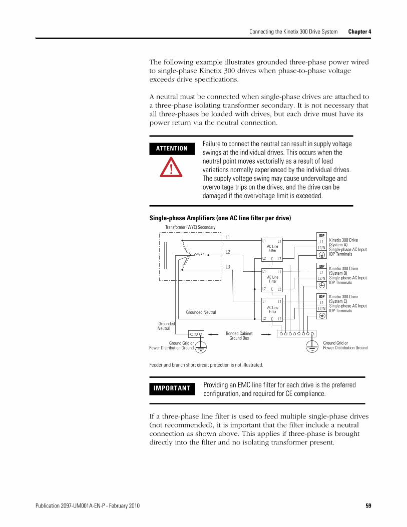
Connecting the Kinetix 300 Drive System Chapter 4
The following example illustrates grounded three-phase power wired to single-phase Kinetix 300 drives when phase-to-phase voltage exceeds drive specifications.
A neutral must be connected when single-phase drives are attached to a three-phase isolating transformer secondary. It is not necessary that all three-phases be loaded with drives, but each drive must have its power return via the neutral connection.
Single-phase Amplifiers (one AC line filter per drive)
Feeder and branch short circuit protection is not illustrated.
If a three-phase line filter is used to feed multiple single-phase drives (not recommended), it is important that the filter include a neutral connection as shown above. This applies if three-phase is brought directly into the filter and no isolating transformer present.
ATTENTIONFailure to connect the neutral can result in supply voltage swings at the individual drives. This occurs when the neutral point moves vectorially as a result of load variations normally experienced by the individual drives. The supply voltage swing may cause undervoltage and overvoltage trips on the drives, and the drive can be damaged if the overvoltage limit is exceeded.
IMPORTANT Providing an EMC line filter for each drive is the preferred configuration, and required for CE compliance.
L1
L2
L3
L1
L2
L1
L2
L1
L2
IDPL1
L2/N
IDPL1
L2/N
IDPL1
L2/N
L1
L2
L1
L2
L1
L2E
E
E
Bonded CabinetGround Bus
Transformer (WYE) Secondary
Ground Grid or Power Distribution Ground
AC LineFilter
AC LineFilter
AC LineFilter
Ground Grid orPower Distribution Ground
Kinetix 300 Drive(System A)Single-phase AC InputIDP Terminals
Grounded Neutral
Grounded Neutral
Kinetix 300 Drive(System B)Single-phase AC InputIDP Terminals
Kinetix 300 Drive(System C)Single-phase AC InputIDP Terminals
Publication 2097-UM001A-EN-P - February 2010 59

Chapter 4 Connecting the Kinetix 300 Drive System
Voiding of CE Compliance
The three-phase and neutral in-line filter applications described above may not be adequate from an EMC aspect for CE compliance. Therefore, EMC validity and CE marking by Rockwell Automation is voided when three-phase and neutral in line filters are used.
ATTENTION The three-phase isolation transformer and neutral in-line filter applications described in this document have not been tested for EMC by Rockwell Automation, and products used in such installations are not considered CE marked by Rockwell Automation.
If this three-phase isolation transformer and neutral in-line filter application is used, the responsibility for EMC validation lies with the user and CE marking of the system becomes the user's responsibility.
If CE compliance is a customer requirement, single-phase line filters which have been tested by Rockwell and specified for the product should be used. Refer to AC Line Filter Specifications on page 132 for catalog numbers.
60 Publication 2097-UM001A-EN-P - February 2010

Connecting the Kinetix 300 Drive System Chapter 4
Grounding Your Kinetix 300 Drive
All equipment and components of a machine or process system should have a common earth ground point connected to their chassis. A grounded system provides a safety ground path for short circuit protection. Grounding your modules and panels minimize shock hazard to personnel and damage to equipment caused by short circuits, transient overvoltages, and accidental connection of energized conductors to the equipment chassis. For CE grounding requirements, refer to CE Requirements in Chapter 1.
Grounding Your System to the Subpanel
If the Kinetix 300 drive is mounted on a painted subpanel, ground to a
bonded cabinet ground bus using a braided ground strap or 4.0 mm2
(12 AWG) solid copper wire 100 mm (3.9 in.) long.
Connecting the Braided Ground Strap Example
For dimensions, Product Dimensions on page 134.
IMPORTANT To improve the bond between the Kinetix 300 drive and subpanel, construct your subpanel out of zinc plated (paint-free) steel.
ATTENTION The National Electrical Code contains grounding requirements, conventions, and definitions. Follow all applicable local codes and regulations to safely ground your system. Refer to the illustration below for details on grounding your Kinetix 300 drive. Refer to Appendix B for the power wiring diagram for your Kinetix 300 drive.
Bonded CabinetGround Bus
Ground Grid or PowerDistribution Ground
Braided Ground Strap
Ground Stud
Publication 2097-UM001A-EN-P - February 2010 61

Chapter 4 Connecting the Kinetix 300 Drive System
Chassis Ground Configuration (multiple Kinetix 300 drives on one panel)
Grounding Multiple Subpanels
To ground multiple subpanels, refer to the figure below. HF bonding is not illustrated. For information, refer to Bonding Multiple Subpanels on page 24.
Subpanels Connected to a Single Ground Point
Bonded Ground Bar (optional)
Bonded Cabinet Ground Bus Ground Grid or Power
Distribution Ground
Always follow NEC andapplicable local codes.
Chassis Ground
Chassis Ground
Chassis Ground
Chassis Ground
Always follow NEC and applicable local codes.
Ground Grid or Power Distribution Ground
Bonded Ground Bus
62 Publication 2097-UM001A-EN-P - February 2010

Connecting the Kinetix 300 Drive System Chapter 4
Power Wiring Requirements
Wire should be copper with 75 C (167 F) minimum rating. Phasing of main AC power is arbitrary and earth ground connection is required for safe and proper operation.
Refer to Power Wiring Examples on page 137 for interconnect diagrams.
IMPORTANT The National Electrical Code and local electrical codes take precedence over the values and methods provided.
Kinetix 300 Drive Power Wiring Requirements
Cat. No. Description Terminals Recommended
Wire Sizemm2 (AWG)
Strip Lengthmm (in.)
Torque Value N•m (lb•in)Pin Signal
2097-V31PR02097-V32PR02097-V32PR22097-V33PR12097-V33PR32097-V34PR32097-V34PR52097-V34PR6
Mains input powerIPD-1IPD-2IPD-3IPD-4
L3L2L1PE
2.5 (14) 7 (0.28) 0.5 (4.5)
2097-V32PR42097-V33PR5 4.0 (12) 7 (0.28) 0.5 (4.5)
2097-V31PR22097-V33PR6 6.0 (10) 7 (0.28) 0.56…0.79
(5.0…7.0)
2097-V31PR02097-V32PR02097-V32PR22097-V32PR42097-V33PR12097-V33PR32097-V33PR52097-V34PR32097-V34PR52097-V34PR62097-V31PR2
Motor powerMP-1MP-2MP-3MP-4
PEWVU
2.5 (14) 7 (0.28) 0.5 (4.5)
2097-V33PR6 4.0 (12) 7 (0.28) 0.5 (4.5)
Publication 2097-UM001A-EN-P - February 2010 63

Chapter 4 Connecting the Kinetix 300 Drive System
Shunt Resistor Power Wiring Requirements
2097-V31PR02097-V32PR02097-V32PR22097-V32PR42097-V33PR12097-V33PR32097-V33PR52097-V34PR32097-V34PR52097-V34PR62097-V31PR2
Brake resistor and DC bus(1)
BC-1BC-2BC-3BC-4BC-5
B+B+BRB-B-
2.5 (14) 7 (0.28) 0.5 (4.5)
2097-V33PR6 4.0 (12) 7 (0.28) 0.5 (4.5)
2097-V3xPRx Control back-up power
BP-1BP-2
+24V DCReturn
1.5 (16) 6 (0.25) 0.5 (4.5)2097-V3xPRx Safe torque-off
STO-1 (2)STO-2 (2)STO-3STO-4STO-5STO-6
+24V DC ControlControl COMSafety StatusSafety Input 1Safety COMSafety Input 2
(1) Use for shunt resistor connection only.(2) Use for bypassing the STO circuit only.
Kinetix 300 Drive Power Wiring Requirements (continued)
Cat. No. Description Terminals Recommended
Wire Sizemm2 (AWG)
Strip Lengthmm (in.)
Torque Value N•m (lb•in)Pin Signal
ATTENTION To avoid personal injury and/or equipment damage, make sure installation complies with specifications regarding wire types, conductor sizes, branch circuit protection, and disconnect devices. The National Electrical Code (NEC) and local codes outline provisions for safely installing electrical equipment.
To avoid personal injury and/or equipment damage, make sure motor power connectors are used for connection purposes only. Do not use them to turn the unit on and off.
To avoid personal injury and/or equipment damage, make sure shielded power cables are grounded to prevent potentially high voltages on the shield.
Accessory DescriptionConnects to Terminals Recommended
Wire Sizemm2 (AWG)
Torque ValueN•m (lb•in)Pin Signal
2097-Rx Shunt ResistorBC-1 or BC-2 B+
2.5 (14) 0.5 (4.5)BC-3 BR
64 Publication 2097-UM001A-EN-P - February 2010

Connecting the Kinetix 300 Drive System Chapter 4
Wiring Guidelines Use these guidelines as a reference when wiring the connectors on your Kinetix 300 drive power modules.
Follow these steps when wiring the connectors on your Kinetix 300 drive modules.
1. Prepare the wires for attachment to each connector plug by removing insulation equal to the recommended strip length.
2. Route the cable/wires to your Kinetix 300 drive.
3. Insert wires into connector plugs.
Refer to connector pinout tables in Chapter 3 or the interconnect diagrams in Appendix B.
4. Tighten the connector screws.
5. Gently pull on each wire to make sure it does not come out of its terminal; reinsert and tighten any loose wires.
6. Insert the connector plug into the module connector.
IMPORTANT For connector locations of the Kinetix 300 drives, refer to Kinetix 300 Drive Connectors and Indicators on page 32.
When tightening screws to secure the wires, refer to the tables beginning on page 63 for torque values.
When removing insulation from wires, refer to the tables beginning on page 63 for strip lengths.
IMPORTANT To improve system performance, run wires and cables in the wireways as established in Establishing Noise Zones on page 25.
IMPORTANT Use caution not to nick, cut, or otherwise damage strands as you remove the insulation.
Publication 2097-UM001A-EN-P - February 2010 65

Chapter 4 Connecting the Kinetix 300 Drive System
Wiring the Kinetix 300 Drive Connectors
This section provides examples and wiring tables to assist you in making connections to the Kinetix 300 drive.
Wiring the Safe Torque-off (STO) Connector
To wire the safe-off connector, refer to Appendix D on page 155.
Wiring the Back-up Power (BP) Connector
Kinetix 300 Drive (BP) Connector
Back-up Power (BP) Connector
+24
-
+24V DC
RETURN
Kinetix 300 Drive, Front View
Cat. No. Terminal Recommended
Wire Sizemm2 (AWG)
Strip Lengthmm (in.)
Torque Value N•m (lb•in)Pin Signal
2097-V3xPRxBP-1 +24V DC
1.5 (16) 6 (0.25) 0.5 (4.5)BP-2 Return
66 Publication 2097-UM001A-EN-P - February 2010

Connecting the Kinetix 300 Drive System Chapter 4
Wiring the Input Power (IPD) Connector
Kinetix 300 Drive (IPD) connector
Input Power (IPD) Connector
L3
L2
L1
PE
L3
L2
L1
Kinetix 300 DriveTop View
Cat. No. Terminal Recommended
Wire Sizemm2 (AWG)
Strip Lengthmm (in.)
Torque Value N•m (lb•in)Pin Signal
2097-V31PR02097-V32PR02097-V32PR22097-V33PR12097-V33PR32097-V34PR32097-V34PR52097-V34PR6
IPD-1IPD-2IPD-3IPD-4
L3L2L1PE
2.5 (14) 7 (0.28) 0.5 (4.5)
2097-V32PR42097-V33PR5 4.0 (12) 7 (0.28) 0.5 (4.5)
2097-V31PR22097-V33PR6 6.0 (10) 7 (0.28) 0.56…0.79
(5.0…7.0)
Publication 2097-UM001A-EN-P - February 2010 67

Chapter 4 Connecting the Kinetix 300 Drive System
Wiring the Motor Power (MP) Connector
Connections to the motor power (MP) connector include rotary motors, and rotary motor driven actuators.
Kinetix 300 Drive (MP) Connector
Cable Shield Terminations
Factory-supplied motor power cables for MP-Series and TL-Series motors and actuator are shielded. The braided cable shield must terminate near the drive during installation. Remove small portion of the cable jacket to expose the shield braid and clamp the exposed shield to the panel.
ATTENTION To avoid hazard of electrical shock, ensure shielded power cables are grounded at a minimum of one point for safety.
IMPORTANT For TL-Series motors, also connect the 152 mm (6.0 in.) termination wire to the closest earth ground.
Refer to Pigtail Terminations on page 69 for more information.
W
V
U
PE
W
V
U
Kinetix 300 DriveBottom View
68 Publication 2097-UM001A-EN-P - February 2010

Connecting the Kinetix 300 Drive System Chapter 4
Pigtail Terminations
TL-Series motors have a short pigtail cable which connects to the motor, but is not shielded. The preferred method for grounding the TL-Series power cable on the motor side is to expose a section of the cable shield and clamp it directly to the machine frame. The motor power cable also has a 150 mm (6.0 in.) shield termination wire with a ring lug that connects to the closest earth ground. Use this method in addition to the cable clamp. The termination wire may be extended to the full length of the motor pigtail if necessary, but it is best to connect the supplied wire directly to ground without lengthening.
Pigtail Terminations
(1) Remove paint from machine frame to ensure proper HF-bond between machine frame and motor case, shield clamp, and ground stud.
Motor Power Cable Compatibility
(1) (1)
Pigtail Cable
TL-SeriesMotor
ConnectorsMotor Power Cable
Machine Frame150 mm (6.0) Termination
Cable Braid Clampedto Machine Frame (1)
Motor/Actuator Connector Motor/Actuator Cat. No. Motor Power Cables(with brake wires)
Motor Power Cables(without brake wires)
MP-Series (Bulletin MPL)
Circular DIN
MPL-A/B15xxx and MPL-A/B2xxx2090-XXNPMF-xxSxx (standard) or 2090-CPBM4DF-xxAFxx (continuous-flex)
2090-CPWM4DF-xxAFxx (continuous-flex)
MPL-A/B3xxx, MPL-A/B4xxx, MPL-A/B45xxx, MPL-A/B5xxx,
2090-XXNPMF-xxSxx (standard)2090-CPBM7DF-xxAFxx (1)(continuous-flex)
2090-CPWM7DF-xxAFxx (1)(continuous-flex)
MP-Series (Bulletin MPS) MPS-A/Bxxxx2090-XXNPMF-xxSxx (standard) or 2090-CPBM4DF-xxAFxx (continuous-flex)
2090-CPWM4DF-xxAFxx (continuous-flex)MP-Series (Bulletin MPAS) MPAS-A/Bxxxx
MP-Series (Bulletin MPAR) MPAR-A/B1xxx and MPAR-A/B2xxx
MP-Series (Bulletin MPM) MPM-A/Bxxxx
2090-XXNPMF-xxSxx (standard)2090-CPBM7DF-xxAFxx (1)(continuous-flex)
2090-CPWM7DF-xxAFxx (1)(continuous-flex)
MP-Series (Bulletin MPF) MPF-A/Bxxxx
MP-Series (Bulletin MPAR) MPAR-A/B3xxx
MP-Series (Bulletin MPAI) MPAI-A/Bxxxx
TL-Series (Bulletin TLY) Circular Plastic
TLY-Axxxx 2090-CPBM6DF-16AAxx (standard)
2090-CPWM6DF-16AAxx (standard) TL-Series (Bulletin TLAR) TLAR-A/Bxxxx
(1) For motors with circular DIN connectors, either 2090-CPxM7DF-xxAFxx, 2090-CPxM4DF-xxAFxx, or 2090-XXNPMF-xxSxx cables are compatible. However, you must remove the motor-side o-ring when using 2090-CPxM7DF-xxAFxx cables.
Publication 2097-UM001A-EN-P - February 2010 69

Chapter 4 Connecting the Kinetix 300 Drive System
The following diagram shows an example of three-phase power wires for motors/actuators that have no brakes. Thermal switch wires are included in the feedback cable.
Refer to Kinetix 300 Drive/Rotary Motor Wiring Examples beginning on page 141 for interconnect diagrams.
Motor Power Terminations (three-phase wires only)
The cable shield clamp shown above is mounted to the subpanel. Ground and secure the motor power cable in your system following instructions on page 74.
Motor Cable Shield Clamp
Motor Power (MP) Connector Plug
Kinetix 300 Drive
70 Publication 2097-UM001A-EN-P - February 2010

Connecting the Kinetix 300 Drive System Chapter 4
The following diagram shows an example of wiring with three-phase power wires and brake wires. The brake wires have a shield braid (shown below as gray) that folds back under the cable clamp before the conductors are attached to the motor brake circuit. Thermal switch wires are included in the feedback cable.
Refer to Kinetix 300 Drive/Rotary Motor Wiring Examples beginning on page 141 for interconnect diagrams.
Motor Power Terminations (three-phase and brake wires)
1
2
3
To Motor
6
7
5
84
Item Description Item Description
1 (1) 24V power supply 5 I/O (IOD) connector.(2)
2 (1) Relay and diode assembly.(3) 6 2097-V3xPRx Kinetix 300 drive.
3 Minimize unshielded wires in brake circuit. 7 Motor power (MP) connector.
4 MP-Series cable brake wires. 8 Cable clamp.(4)
(1) User supplied. Size as required by motor brake, See Motor Brake Currents on page 148.
(2) Configure one emitter and collector pair from the Digital Outputs, OUT-1… OUT-4, pins 43…50, as Brake+ and Brake - using MotionView software. Wire the output as sourcing and set brake engage and disengage times for motor selected. Motor brake is active on enable. For Digital Output specifications, refer to page 48
(3) Diode 1N4004 rated 1.0A @ 400V DC. See Wiring Examples beginning on page 141.
(4) Exposed shield under clamp and place within 2…3 in. (50…75 mm) of drive, see page 74 for details.
Publication 2097-UM001A-EN-P - February 2010 71
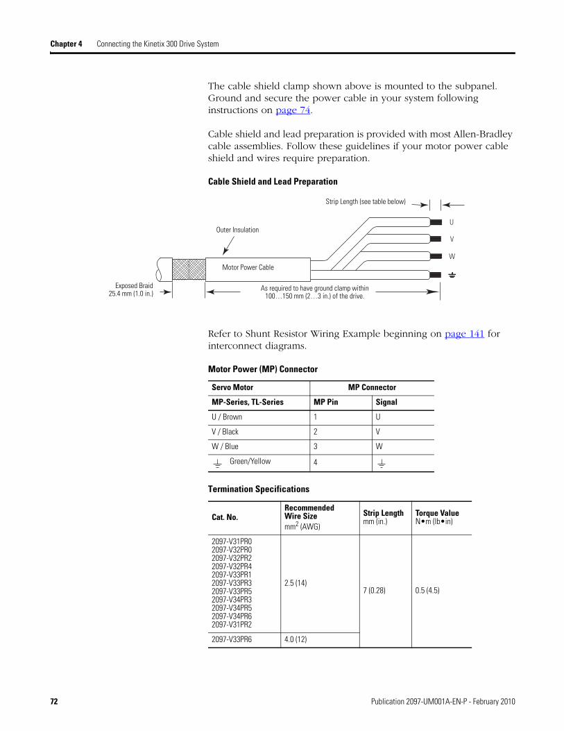
Chapter 4 Connecting the Kinetix 300 Drive System
The cable shield clamp shown above is mounted to the subpanel. Ground and secure the power cable in your system following instructions on page 74.
Cable shield and lead preparation is provided with most Allen-Bradley cable assemblies. Follow these guidelines if your motor power cable shield and wires require preparation.
Cable Shield and Lead Preparation
Refer to Shunt Resistor Wiring Example beginning on page 141 for interconnect diagrams.
Motor Power (MP) Connector
Termination Specifications
W
V
U
Motor Power Cable
Exposed Braid 25.4 mm (1.0 in.)
Outer Insulation
As required to have ground clamp within 100…150 mm (2…3 in.) of the drive.
Strip Length (see table below)
Servo Motor MP Connector
MP-Series, TL-Series MP Pin Signal
U / Brown 1 U
V / Black 2 V
W / Blue 3 W
Green/Yellow 4
Cat. No.RecommendedWire Sizemm2 (AWG)
Strip Lengthmm (in.)
Torque Value N•m (lb•in)
2097-V31PR02097-V32PR02097-V32PR22097-V32PR42097-V33PR12097-V33PR32097-V33PR52097-V34PR32097-V34PR52097-V34PR62097-V31PR2
2.5 (14) 7 (0.28) 0.5 (4.5)
2097-V33PR6 4.0 (12)
72 Publication 2097-UM001A-EN-P - February 2010

Connecting the Kinetix 300 Drive System Chapter 4
Wiring the Shunt Resistor
If you are using a shunt resistor in your system, wire it to the BC connector using instructions found in the Kinetix 300 Shunt Resistor Installation Instructions, publication 2097-IN002.
Brake/DC Bus (BC) Connector
B+B+
BR
B-B-
Kinetix 300 Drive Front view is shown.
Brake /DC Bus (BC) Connector
Publication 2097-UM001A-EN-P - February 2010 73
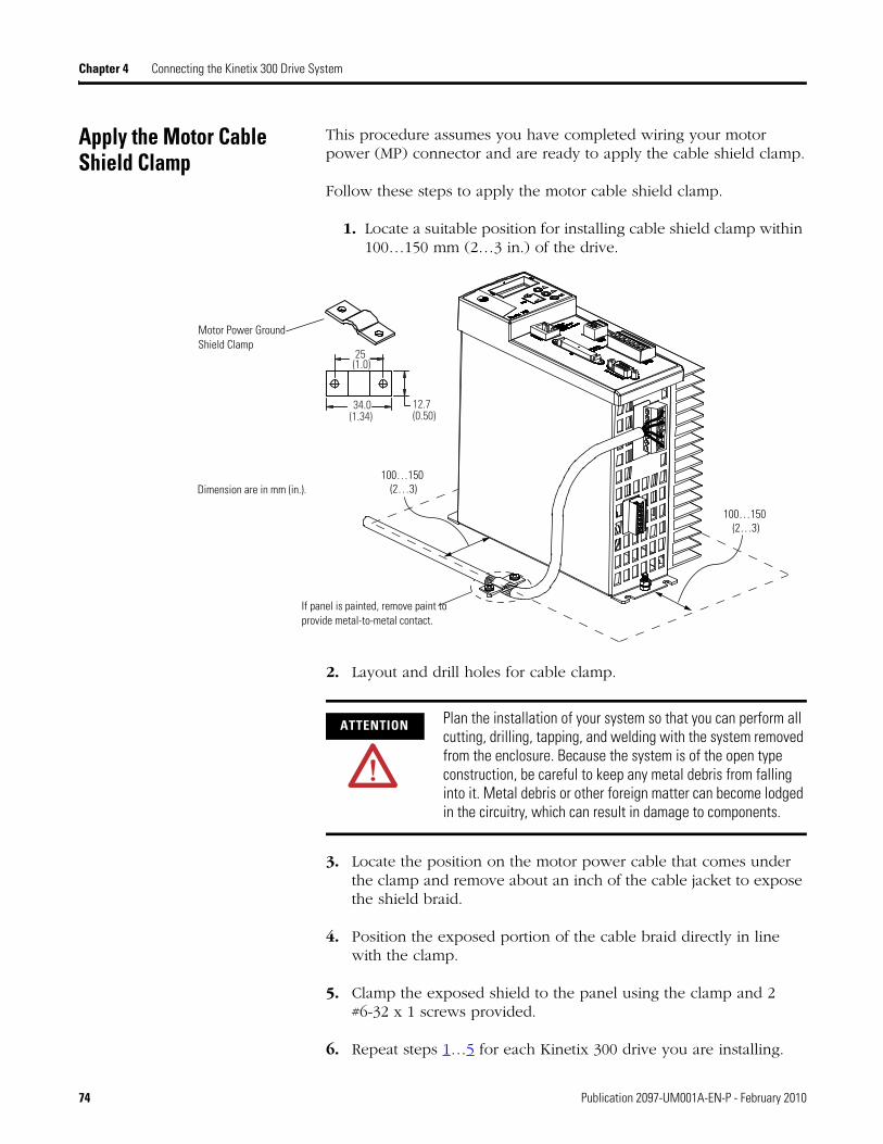
Chapter 4 Connecting the Kinetix 300 Drive System
Apply the Motor Cable Shield Clamp
This procedure assumes you have completed wiring your motor power (MP) connector and are ready to apply the cable shield clamp.
Follow these steps to apply the motor cable shield clamp.
1. Locate a suitable position for installing cable shield clamp within 100…150 mm (2…3 in.) of the drive.
2. Layout and drill holes for cable clamp.
3. Locate the position on the motor power cable that comes under the clamp and remove about an inch of the cable jacket to expose the shield braid.
4. Position the exposed portion of the cable braid directly in line with the clamp.
5. Clamp the exposed shield to the panel using the clamp and 2 #6-32 x 1 screws provided.
6. Repeat steps 1…5 for each Kinetix 300 drive you are installing.
100…150 (2…3)
100…150 (2…3)
34.0(1.34)
25 (1.0)
12.7(0.50)
If panel is painted, remove paint to provide metal-to-metal contact.
Motor Power Ground Shield Clamp
Dimension are in mm (in.).
ATTENTION Plan the installation of your system so that you can perform all cutting, drilling, tapping, and welding with the system removed from the enclosure. Because the system is of the open type construction, be careful to keep any metal debris from falling into it. Metal debris or other foreign matter can become lodged in the circuitry, which can result in damage to components.
74 Publication 2097-UM001A-EN-P - February 2010

Connecting the Kinetix 300 Drive System Chapter 4
Understanding Feedback and I/O Cable Connections
Factory made cables with premolded connectors are designed to minimize EMI and are recommended over hand-built cables to improve system performance. However, other options are available for building your own feedback and I/O cables.
Options for Connecting Motor Feedback
Motor Feedback Cables for Specific Motor/Feedback Combinations
Connection Option Cat. No. Cable Using This Type of Cable
Premolded connectors N/A Motor feedback Refer to the table below for the premolded motor feedback cable available for your motor.
Low-profile connector 2090-K2CK-D15M Motor feedback Refer to the table below for the flying-lead cable available for your motor.
I/O Terminal Block 2097-TB1 I/O interface User-supplied flying-lead cable.
Motor Cat. No. Feedback TypeFeedback Cable
PinoutPremolded Flying-lead
MPL-A/B3xxx-M/S…MPL-A/B45xxx-M/S
High-resolution encoder
N/A
2090-XXNFMF-Sxx (standard)2090-CFBM7DF-CDAFxx (continuous-flex)
page 76
MPL-A/B3xxx-H…MPL-A/B45xxx-H
MPM-A/Bxxxxx-M/S
MPF-A/Bxxxx-M/S
MPAR-A/B3xxxx
MPAI-A/Bxxxx
MPL-A/B15xxx-V/EMPL-A/B2xxx-V/E
2090-XXNFMF-Sxx (standard)2090-CFBM4DF-CDAFxx (continuous-flex)
MPS-A/Bxxxx-M/S
MPAR-A/B1xxxx and MPAR-A/B2xxxx
MPAR-A/B3xxxx
MPL-A/B15xxx-HMPL-A/B2xxx-H Incremental encoder
TLY-Axxxx-BHigh-resolution encoder 2090-CFBM6DF-CBAAxx
(standard) or page 77TLAR-Axxxxx
TLY-Axxxx-H Incremental encoder 2090-CFBM6DD-CCAAxx
Publication 2097-UM001A-EN-P - February 2010 75

Chapter 4 Connecting the Kinetix 300 Drive System
Flying-lead Feedback Cable Pin-outs
2090-XXNFMF-Sxx or 2090-CFBMxDF-CDAFxx Feedback Cable
Circular DINConnector High-resolution Feedback Incremental
Feedback Drive MFConnector PinRotary Motor
Connector Pin 9V Encoder 5V Encoder 5 V Encoder
1 Sin+ Sin+ AM+ 1
2 Sin- Sin- AM- 2
3 Cos+ Cos+ BM+ 3
4 Cos- Cos- BM- 4
5 Data+ Data+ IM+ 5
6 Data- Data- IM- 10
9 Reserved EPWR_5V EPWR_5V 14
10 Reserved ECOM ECOM 6
11 EPWR_9V Reserved Reserved 7
12 ECOM Reserved Reserved 6
13 TS+ TS+ TS+ 11
14 TS- TS- TS- –
15 Reserved Reserved S1 12
16 Reserved Reserved S2 13
17 Reserved Reserved S3 8
76 Publication 2097-UM001A-EN-P - February 2010

Connecting the Kinetix 300 Drive System Chapter 4
2090-CFBM6DF-CBAAxx Feedback Cable
Wiring I/O Connector
Connect your I/O wires to the IOD connector using a 2097-TB1 I/O Terminal Expansion Block. Wiring and installation instructions are found in the Kinetix 300 I/O Terminal Expansion Block Installation Instructions, publication 2097-IN005.
Kinetix 300 Drive (IOD connector and terminal block)
Rotary Motor Connector Pin
High Resolution Incremental Feedback Drive MFConnector PinTLY-Axxxx-B TLY-Axxxx-H
6 BAT+ Reserved BAT+
9
Reserved
AM+ 1
10 AM- 2
11 BM+ 3
12 BM- 4
13 DATA+ IM+ 5
14 DATA- IM- 10
15
Reserved
S1 12
17 S2 13
19 S3 8
22 EPWR 5V EPWR 5V 14
23 ECOM and BAT- ECOM 6
24 Shield Shield Connector housing
1
11122021
29
30
40
50GND
I/O (IOD) Connector
2097-TB1 I/O Terminal Expansion Block
Publication 2097-UM001A-EN-P - February 2010 77

Chapter 4 Connecting the Kinetix 300 Drive System
Wiring Feedback Connector
These procedures assume you have mounted your Kinetix 300 system, completed all power wiring, and are ready to connect your feedback.
Wiring Low-profile Connector Kit
The 2090-K2CK-D15M low-profile connector kit is suitable for terminating flying-lead motor feedback cables. Use it with the Kinetix 300 drive and all motors with incremental or high-resolution feedback. It has a 15-pin, male, D-sub connector and is compatible with all Bulletin 2090 feedback cables.
TLY-Axxxx-B high-resolution motors with 17-bit encoder require a 3.6V battery, purchased separately, (catalog number 2090-DA-BAT2).
Kinetix 300 Drive (MF connector)
Wiring (15-Pin) Flying-lead Feedback Cable Connections2090-K2CK-D15M Connector Kit
2090-K2CK-D15M Connector Kit with flying-lead feedback cable.
Motor Feedback (MF) Connector
Kinetix 300 Drive Front View(2097-V33PR5 drive is shown)
Kinetix 300 Drive, Side View(2097-V33PR5 drive is shown)
12
34
56
78
910
1112
1314
150
Pin 1
Pin 10Pin 5
Pin 11Pin 6
Pin 15
15-pin (male) Motor FeedbackLow-profile Connector
Refer to Chapter 3 for feedback signal descriptions.
TieWrap
Exposed Braid Under Clamp
Bulletin 2090 Feedback Cable
Clamp
Outer Insulation
Braided Shield
Foil Shield
Wire Insulation
Bare Wires
Bulletin 2090 Feedback Cable
Turn clamp over to holdsmall wires secure.
Mounting Screws
Refer to page 141 for the motor feedback interconnect drawing for your application.
3.6V battery (catalog number 2090-DA-BAT2) onlyrequired for use with TLY-Axxxx-B motors(high-resolution 17-bit encoders).Low Profile Connector Kit
(2090-K2CK-D15M)
78 Publication 2097-UM001A-EN-P - February 2010
Connecting the Kinetix 300 Drive System Chapter 4
Understanding Shunt Resistor Connections
Follow these guidelines when wiring your 2097-Rx shunt resistor.
Refer to Shunt Resistors on page 28 for noise zone considerations.
Refer to Shunt Resistor Wiring Example on page 140.
Refer to the installation instructions provided with your Bulletin 2097 shunt resistor, publication 2097-IN002.
IMPORTANT When tightening screws to secure the wires, refer to the tables beginning on page 63 for torque values.
IMPORTANT To improve system performance, run wires and cables in the wireways as established in Chapter 2.
Publication 2097-UM001A-EN-P - February 2010 79

Chapter 4 Connecting the Kinetix 300 Drive System
Connecting Your Ethernet Cables
This procedure assumes you have your Logix Ethernet/IP module and Kinetix 300 drive mounted and ready to connect the network cables.
The EtherNet/IP network is connected using the Port 1 connector. Refer to page 32 to locate the Ethernet connector on your Kinetix 300 drive. Refer to the figure below to locate the connector on your Logix communication module.
Shielded Ethernet cable is available in lengths up to 78 m (256 ft). However, the total length of Ethernet cable connecting drive-to-drive, drive-to-controller, or drive-to-switch must not exceed 100 m (328 ft).
If the entire channel is constructed of stranded cable (no fixed cable), then this is the equation for calculating maximum length:
Maximum Length = (113-2N)/y, meters where N = the number of connections in the channel and y = the loss factor compared to fixed cable (typically 1.2…1.5).
Compact Logix Ethernet Port Location
The Port 1 Ethernet connection is used for connecting to a web browser and configuring your Logix module.
Ethernet Wiring Example - External Switch
CompactLogix L23E
Ethernet Port
CompactLogix Controller Platform1769-L23E-QB1B Shown
CompactLogix L23E
0030000300
CompactLogix Controller Platform1769-L23E-QB1B Shown
Personal Computer
1783-EMS08T Stratix 6000 Switch
Kinetix 300 Drives
80 Publication 2097-UM001A-EN-P - February 2010

Chapter 5
Configure and Start Up the Kinetix 300 Drive
Introduction This chapter provides procedures for configuring your Kinetix 300 drive components.
Topic Page
Introduction 81
Keypad Input 82
Configure the Kinetix 300 Drive Ethernet IP Address 84
Use the Kinetix 300 MotionView OnBoard Tool 89
Configure the Logix EtherNet/IP Interface Module 97
Apply Power to the Kinetix 300 Drive 101
Test and Tune the Axis 102
Tune the Axis 103
Select Drive Operating Mode 105
Configure Master Gearing Mode 106
Configure Drive Parameters and System Variables 108
Configuring Drive Mode Using Explicit Messaging 111
Publication 2097-UM001A-EN-P - February 2010 81

Chapter 5 Configure and Start Up the Kinetix 300 Drive
Keypad Input The Kinetix 300 drive is equipped with a diagnostic status indicator and three push buttons that are used to select displayed information and to edit a limited set of parameter values. Parameters can be
scrolled by using . To view a value, press . To return back to
Scroll mode press .
After pressing on editable parameters, the yellow status indicator C blinks indicating that the parameter value can be changed. Use
to change the value. Press to store the new setting and return back to Scroll mode.
Status Display Information
Status Indicator Description
StAt Current drive status - run - drive running, diS - drive disabled, EXX - Drive fault. Where XX is the fault code.
Hx.xx Hardware revision. For example, H2.00.
Fx.xx Firmware revision. For example, F2.06.
FLtS Stored fault's history. You can scroll through stored faults E0XX - E7XX, where XX is the fault code.
Ht Heatsink temperature. Heatsink temperature in is shown ºC if greater than 40ºC. Otherwise ‘LO’ (low) is displayed.
EnC Encoder activity. Primary encoder counts are displayed for encoder diagnostics.
buS Displays drive DC bus voltage.
Curr Displays motor's phase current (RMS). Shows current value if drive is enabled, otherwise shows DiS.
boot 0 = autostart disabled, 1 = autostart enabled.
dHCP Ethernet DHCP Configuration: 0=’dHCP’ is disabled; 1=’dHCP’ is enabled.
IP_1 First octet of the IP address.
IP_2 Second octet of the IP address.
IP_3 Third octet of the IP address.
IP_4 Fourth octet of the IP address (changeable).
82 Publication 2097-UM001A-EN-P - February 2010

Configure and Start Up the Kinetix 300 Drive Chapter 5
Status Indicators
The Kinetix 300 drive has five status indicators located around the periphery of the front panel display as shown below. These status indicators used to monitor the system status, activity, and troubleshoot faults.
Front Panel Display
Status Indicators
Status Indicator Function Description
A Enable Orange status indicator means that the drive is enabled (running).
B Regen Yellow status indicator means the drive is in Regeneration mode.
C Data entry Yellow status indicator flashes when changing.
D Drive fault Red status indicator illuminates upon a drive fault.
E Comm activity Green status indicator flashes to indicate communication activity.
Publication 2097-UM001A-EN-P - February 2010 83

Chapter 5 Configure and Start Up the Kinetix 300 Drive
Configure the Kinetix 300 Drive Ethernet IP Address
This section offers guidance on configuring your Ethernet connection to the Kinetix 300 drive.
Ethernet Connection
Configuration, programming, and diagnostics of the Kinetix 300 drive are performed over the standard 10/100 Mbps Ethernet communication port using the ‘MotionView OnBoard’ software contained within the drive itself.
To access the MotionView OnBoard software, the Kinetix 300 drive and your personal computer must be configured to operate on the same Ethernet network. The IP addresses of the Kinetix 300 drive, the personal computer, or both drive and personal computer may require configuring to enable Ethernet communication between the two devices.
Kinetix 300 Drive Ethernet Port Configuration
The IP address of the Kinetix 300 drive is composed of four sub-octets that are separated by three dots to conform to the Class C Subnet structure. Each sub-octet can be configured with number between 1 and 254. As shipped from the factory the default IP address of a drive is 192.168.124.120.
There are two methods of changing the current IP address. An address can be assigned to the drive automatically (dynamic IP address) when the drive is connected to a DHCP (Dynamic Host Configuration Protocol) enabled server, or the drive can have an IP address assigned to it manually be the user (static IP address). Both methods of configuring the drive’s IP address are shown here.
TIP To run MotionView OnBoard on a Mac OS, run the personal computer emulation tool first.
IMPORTANT Any changes made to the Ethernet communication settings on the Kinetix 300 drive do not take effect until the drive is powered off and powered on again. Until the power is cycled the drive continues to use its previous settings.
TIP For personal computers with an Ethernet port that is used for a specific purpose, such as email or web browsing, it may be more convenient for you to add an Ethernet port to the personal computer.
Installing a USB/Ethernet dongle or a PCMCIA Ethernet card is an easy way to gain an additional port for communication to the Kinetix 300 drive.
84 Publication 2097-UM001A-EN-P - February 2010

Configure and Start Up the Kinetix 300 Drive Chapter 5
Obtaining the Kinetix 300 Drives’ Current Ethernet Settings
The current Ethernet setting and IP address of the Kinetix 300 drive
can be obtained from the drive display and keypad. Press on the
display and use to access parameters IP_1, IP_2, IP_3 and
IP_4. Each of these parameters contain one sub-octet of the full IP address, for example in the case of the drive default (factory set) address parameters:
IP_1 = 192IP_2 = 168IP_3 = 124IP_4 = 120
By accessing these four parameters the full IP address on the drive can be obtained.
If parameters IP_1, IP_2, IP_3 and IP_4 all contain ‘----‘ rather than a numerical values it means that the drive has DHCP enabled and the DHCP server is yet to assign the drive its dynamic IP address. As soon as an IP address is assigned by the server the address assigned is displayed by the drive in the above parameters. See Configuring the IP Address Automatically (dynamic address) on page 87.
Configuring the IP Address Manually (static address)
When connecting directly from the Kinetix 300 drive to the personal computer without a server or when connecting to a private network, where all devices have static IP addresses, assign the IP address of the Kinetix 300 manually.
To assign the address manually, disable the DHCP mode. Do this by using the drive keypad and following these steps.
1. Press .
2. Use to access parameter DHCP.
3. Check this parameter is set to a value of 0.
If the DHCP parameter is set to 1 then use and to set to 0.
4. Cycle power to the drive.
The change takes effect.
Publication 2097-UM001A-EN-P - February 2010 85

Chapter 5 Configure and Start Up the Kinetix 300 Drive
When DHCP is disabled and power cycled to the drive, it reverts back to its previous static IP address.
If you are connecting more than one drive to the personal computer create unique IP address for each drive. Do this by using the keypad on each drive to change the IP_4 parameter. IP_4 is the only octet that can be changed via the keypad. IP_1, IP2, and IP_3 are read-only accessed this way. The dive power must be cycled for any changes to take effect.
To configure the Kinetix 300 drive for specific subnet or change its full IP address, use the MotionView configuration tool.
1. Run a Java enabled web browser.
2. Enter the drive's current IP address into the browser.
MotionView OnBoard dialog box is displayed.
1. Click Run.
1. Click Connect
2. Enter the drive's IP address
3. Click Connect.
4. From the Drive Oganizer, choose Communications>Ethernet.
The IP address, subnet mask, and default gateway address can be edited in this screen. If the text turns red when entered the values or format used are invalid and they are not applied.
86 Publication 2097-UM001A-EN-P - February 2010
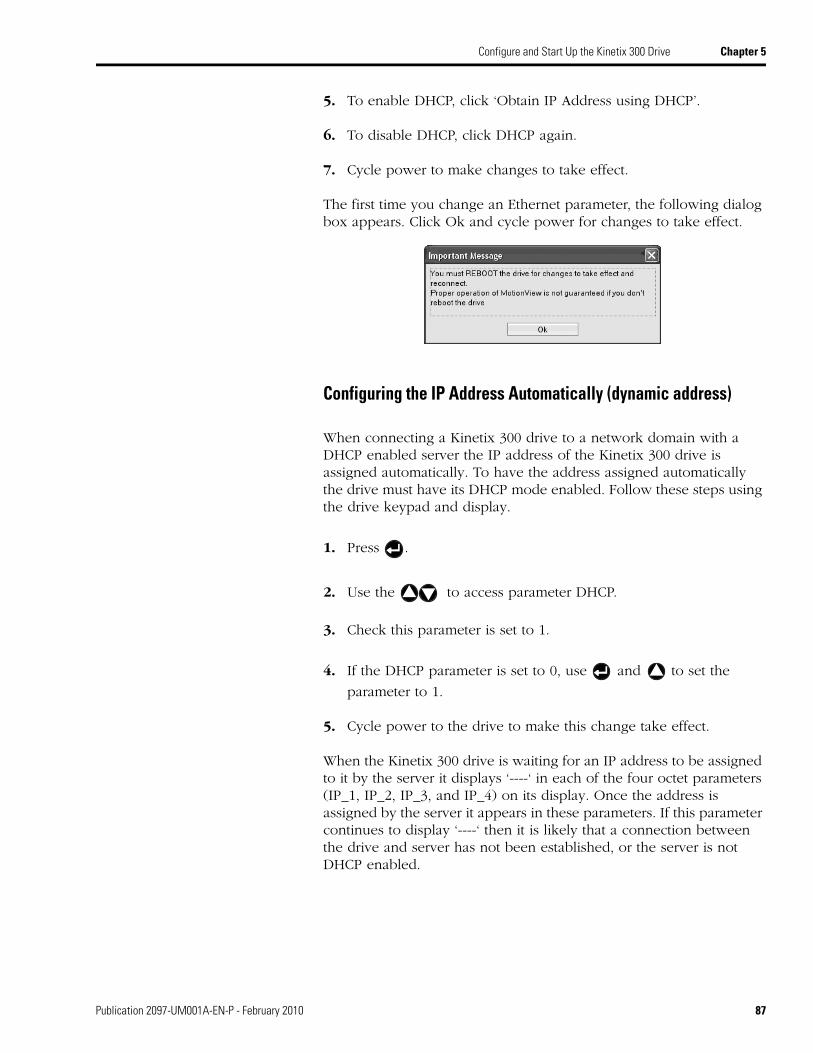
Configure and Start Up the Kinetix 300 Drive Chapter 5
5. To enable DHCP, click ‘Obtain IP Address using DHCP’.
6. To disable DHCP, click DHCP again.
7. Cycle power to make changes to take effect.
The first time you change an Ethernet parameter, the following dialog box appears. Click Ok and cycle power for changes to take effect.
Configuring the IP Address Automatically (dynamic address)
When connecting a Kinetix 300 drive to a network domain with a DHCP enabled server the IP address of the Kinetix 300 drive is assigned automatically. To have the address assigned automatically the drive must have its DHCP mode enabled. Follow these steps using the drive keypad and display.
1. Press .
2. Use the to access parameter DHCP.
3. Check this parameter is set to 1.
4. If the DHCP parameter is set to 0, use and to set the
parameter to 1.
5. Cycle power to the drive to make this change take effect.
When the Kinetix 300 drive is waiting for an IP address to be assigned to it by the server it displays ‘----‘ in each of the four octet parameters (IP_1, IP_2, IP_3, and IP_4) on its display. Once the address is assigned by the server it appears in these parameters. If this parameter continues to display ‘----‘ then it is likely that a connection between the drive and server has not been established, or the server is not DHCP enabled.
Publication 2097-UM001A-EN-P - February 2010 87

Chapter 5 Configure and Start Up the Kinetix 300 Drive
DHCP can be enabled through the MotionView software. If you choose to configure the drive using a manual (static) IP address, you can switch over to an automatic (dynamic) address once configuration is complete. See Obtaining the Kinetix 300 Drives’ Current Ethernet Settings on page 85 for information on enabling DHCP from within the MotionView software.
TIP A useful feature of the MotionView software and communication interface to the Kinetix 300 drive is the ability to assign the drive a name (text string). This name can then be used to discover the drive’s IP address and is useful when the drive has its IP address assigned automatically by the server for easy connection.
88 Publication 2097-UM001A-EN-P - February 2010

Configure and Start Up the Kinetix 300 Drive Chapter 5
Use the Kinetix 300 MotionView OnBoard Tool
The Kinetix 300 drives contains Kinetix 300 MotionView OnBoard software, in short ‘MotionView’, for configuration of the drive. Follow these steps to connect to the software.
1. Open a Java enabled web browser on the host personal computer.
2. Enter the IP address of the drive into the Address field of the browser.
A File Download dialog box will prompt you to Open or Save the MotionView.jnlp file.
3. Click Open.
If the digital signature of the file cannot be verified, Click Run to continue running the application.
The MotionView dialog box is displayed.
4. Click Connect.
The Connection dialog box is displayed.
Publication 2097-UM001A-EN-P - February 2010 89

Chapter 5 Configure and Start Up the Kinetix 300 Drive
5. Enter the IP address for the drive.
6. Click Connect.
When connected the drive will appear in the Drive Organizer on the left side of the MotionView dialog box.
Kinetix 300 MotionView OnBoard Menu
Across the top of the MotionView dialog box are control options for working with the drive. A description of their functions is shown in the following table.
MotionView Control Functions
Function Description
Connect Connect the MotionView software to one or more drives, multiple drives can be connected to a single instance of MotionView.
Disconnect Disconnect from the currently selected drive.
Save connection Save the connection information from the currently connected drives to a file. If multiple drives are connected, connection information for all drives is saved.
Load connection Load a previously saved connection, if multiple drives were saved then multiple drive connections will be opened.
Print Print the configuration of the selected drive.
Save configuration Saves the configuration of the currently selected drive to a file.
Load configuration Copies the configuration from a file into the selected drive.
Restore defaults Restore factory defaults to all drive parameters.
Upgrade Upgrade the firmware in the drive.
Stop/Reset Disables and resets faults on the currently selected drive.
90 Publication 2097-UM001A-EN-P - February 2010

Configure and Start Up the Kinetix 300 Drive Chapter 5
Configuring Drive Using Kinetix 300 MotionView OnBoard Software
On the left side of MotionView software is the Drive Organizer. The Drive Organizer shows node address for the drives that are currently connected to the software and lists the information for each drive under the drive node address. This section contains a description of the parameters displayed in windows listed in the Drive Organizer.
Drive Identification
Drive Identification is labeled with the drive name, IP address, drive name, and status, the window displays drive identification information such as catalog number and firmware revision. In this window you can assign the Drive Name and the Group ID.
Drive Identification and Organizer
Motor
Motor window displays motor information and allows you to change the motor.
Allen-Bradley motors and actuators with intelligent feedback devices will automatically be populated into the motor configuration.
For Allen-Bradley motors and actuators with incremental encoders, click Change Motor and choose the device from the provided list.
Drive Identification
Drive Organizer
Publication 2097-UM001A-EN-P - February 2010 91

Chapter 5 Configure and Start Up the Kinetix 300 Drive
General
The General window displays basic configuration of motion with modifiable parameters shown in the following table.
Ethernet Communication
The Ethernet window displays the IP address configuration. Here you can set your drive to obtain the IP address automatically using DHCP or set the values manually.
EtherNet/IP Network (CIP)
The EtherNet/IP (CIP) window displays the modifiable drive object parameters that are used in the Input and Output AssemblyEtherNet/IP data links.
General Parameters
Parameter Description
Current Limits
By default these values are set based on the configured motor, if these values are set lower than the motor capabilities the drive will report CurrentLimitStatus in the EtherNet/IP Input assembly at the new value but will not clamp the current output until it reaches the motor peak current.
Velocity Mode Acceleration These values only apply if the drive is in a velocity mode over EtherNet/IP External Reference. In Indexing the limits within the individual indexes apply, in a positioning mode over EtherNet/IP External Reference the limits in the Output Assembly apply.
Fault Reset Configuration of when the drive should clear the current fault.
Motor Temperature Sensor By default this value will be set based on the configured motor
Master Encoder Configuration of the Master Gearing functionality
EtherNet/IP (CIP) Parameters
Parameter Description
Enable Determines if the parameter should be copied into or out of the assembly, even if the data link is disabled empty data will still be transferred over EtherNet/IP network.
Parameter ID Number The drive object ID number that the data link should map to, see Appendix F for full list of drive parameters.
92 Publication 2097-UM001A-EN-P - February 2010

Configure and Start Up the Kinetix 300 Drive Chapter 5
Digital I/O
The Digital I/O window displays the configuration of the modifiable digital I/O parameters which are shown in the following table.
Analog I/O
The Analog I/O window displays the configuration of the modifiable analog I/O parameters which are shown in the following table.
IMPORTANT Drive object parameters of type DINT can only be used in the RAM integer data links, parameters of type REAL can only be used in the RAM float data links.
Digital I/O Parameters
Parameter Description
Input Function Configuration of the specific function for the individual digital inputs, pre-assigned inputs such as Enable and Registration are not configurable.
Output Function Configuration of the specific function for the individual digital outputs.
Debounce Time Debounce time in ms of the individual digital inputs.
Hard Limit Switches Action Configuration of the action to take when the limit switches are asserted.
Enable Switch Function Configuration of the enable digital input A3 as either: Run - enable drive when asserted. Inhibit - must be asserted before the drive can be enabled.
Brake Engage Delay Configuration of the engage delay of the motor holding brake.
Brake Release Delay Configuration of the release delay of the motor holding brake.
Analog I/O Parameters
Parameter Description
Analog Output Source of the analog output values
Analog Output (Current Scale) Scaling in V/A of the analog output for output values that are current based.
Analog Output (Velocity Scale) Scaling in mV/rpm of the analog output for output values that are velocity based.
Analog Input (Current Scale) Scaling in A/V of the analog input for output values that are current based.
Analog Input (Velocity Scale) Scaling in rpm/V of the analog input for output values that are velocity based.
Analog Input Dead-Band The number of mV when the input voltage is below will still be treated as 0V.
Analog Input Offset The offset from 0V for the analog input, click the << to set the offset to the current value of the analog input.
Publication 2097-UM001A-EN-P - February 2010 93

Chapter 5 Configure and Start Up the Kinetix 300 Drive
Velocity Limits
The Velocity Limits window displays the configuration of the modifiable velocity limits parameters which are shown in the following table.
Position Limits
The Position Limits window displays the configuration of the modifiable position limits parameters which are shown in the following table.
Velocity Limits Parameters
Parameter Description
Zero Speed Absolute value in User Units/s below which the drive will set the Zero Speed Digital Output, if configured, and the VelocityStandstillStatus bit in the EtherNet/IP Input Assembly.
At Speed Value in User Units/s for the target velocity for which the drive will set the In-Speed Window Digital Output, if configured, and the VelocityLockStatus bit in the EtherNet/IP Input Assembly.
Speed Window The range in User Units/s around the At Speed for setting the In-Speed Window Digital Output, if configured, and the VelocityLockStatus bit in the EtherNet/IP Input Assembly.
Position Limits Parameters
Parameter Description
Position Error The tolerance in encoder counts around the commanded position outside of which the drive will assert a Excess Position Error Fault when the Max Error Time is exceeded.
Max Error Time The amount of time in ms that the drive can be outside of the Position Error before the drive asserts a Excess Position Error Fault.
Abort Decel
The deceleration rate in User Units/s2 that the drive will use to bring the motor to a stop when either the Abort Homing or Abort Index Digital Inputs is asserted, if configured, or either the AbortIndex or AbortHoming bit is set in the EtherNet/IP Output Assembly.
Position Limit The tolerance in User Units around the commanded position inside of which the drive will set the PositionLockStatus bit in the EtherNet/IP Input Assembly.
Soft Limits Off or On depending if software travel limits should be used.
Positive Limit and Negative Limit
If Soft Limts are On, the position in User Units when reached the drive will assert a Software Overtravel fault.
94 Publication 2097-UM001A-EN-P - February 2010

Configure and Start Up the Kinetix 300 Drive Chapter 5
Dynamics
The Dynamics window displays the configuration of the modifiable dynamics parameters which are shown in the following table.
Indexing
The Indexing window displays the configuration of the modifiable indexing parameters which are shown in the following table.
Dynamics Parameters
Parameter Description
Velocity P-Gain The proportional and integral gain of the velocity loops, gains are based on counts as the fundamental units and they are not physical units.Velocity I-Gain
Position P-Gain The proportional, integral, and derivative gain of the position loops, gains are based on counts as the fundamental units and they are not physical units.Position I-Gain
Position D-Gain
Position I-Limit A clamping limit on the position loop I-gain compensator to prevent excessive torque overshooting caused by an over accumulation of the I-gain
Gain Scaling A 2n factor applied to the gains in the velocity loop useful for scaling the gains when using encoders with a high number of counts per revolution such as the MPL-Series motors
Autotuning Click this button to begin the auto tuning of the drive
Indexing Parameters
Parameter Description
Index Type Absolute registration, incremental registration or blended incremental.
Move Type Trapezoidal or s-curve.
Distance The incremental distance to move or target position, based on Index Type.
Batch Count How many times to execute index before moving on to next index.
Dwell The number ms to remain at position before moving on to next index, it is not applied between batches.
Velocity The target speed in User Units/s when moving towards new position, axis may not actually reach the target velocity if the acceleration rate is too low.
Acceleration The rate in User Units/s2 when accelerating towards velocity.
Deceleration The rate in User Units/s2 when deceleration towards zero velocity.
Next Index The next index to execute after the current index completes.
Action When Complete Stop, wait for start, or next index.
Publication 2097-UM001A-EN-P - February 2010 95

Chapter 5 Configure and Start Up the Kinetix 300 Drive
Homing
The Homing window displays the configuration of the modifiable homing parameters which are shown in the following table.
Tools
The tools screen provides access to the oscilloscope and parameter viewer drive tools.
Monitor
The monitor screen provides access to pre-configured status information for the drive. This information is displayed in a floating window that updates in real time.
Faults
The Faults window displays the configuration of the modifiable faults parameters which are shown in the following table.
Homing Parameters
Parameter Description
Home Accel/Decel The rates in User Units/s2 the drive should use in accelerating to or from the homing velocities.
Home Offset The difference between the zero position for the application and the machine home position found during homing.
Home Velocity Fast (or Slow) The velocity in User Units/s to be used in homing based on home method.
Home Switch The digital input that should be used as a home switch for appropriate homing method.
Home Method (1)
(1) Home-to-torque is not available.
A list of action combinations of switch, marker, and immediate for defining the axis home.
Faults Parameters
Parameter Description
Last Fault Code The last fault the drive reported.
Device Time The time since boot of the drive that the fault occurred.
Load Faults Recall the last 15 faults the drive reported.
Clear Fault History Clear the fault history of the drive.
Clear Faults Clear the current fault in the drive.
96 Publication 2097-UM001A-EN-P - February 2010

Configure and Start Up the Kinetix 300 Drive Chapter 5
Configure the Logix EtherNet/IP Interface Module
This procedure assumes that you have wired your Kinetix 300 drive.
For help using RSLogix 5000 software as it applies to configuring the ControlLogix, CompactLogix, or SoftLogix EtherNet/IP modules, refer to Additional Resources on page 10.
Configure the Logix Controller
Follow these steps to configure the Logix controller.
1. Apply power to your Logix chassis containing the Ethernet interface module/PCI card and open your RSLogix 5000 software.
2. From the File menu, choose New.
The New Controller dialog box opens.
3. Configure the new controller.
a. Choose controller type.
b. Choose your RSLogix 5000 software version.
c. Name the file.
d. Choose the Logix chassis size.
e. Enter the Logix processor slot.
4. Click OK.
5. From the Edit menu, choose Controller Properties.
IMPORTANT For the Kinetix 300 drive to communicate with the Ethernet interface module, your RSLogix 5000 software must be version 17.00 or later.
Publication 2097-UM001A-EN-P - February 2010 97

Chapter 5 Configure and Start Up the Kinetix 300 Drive
The Controller Properties dialog box opens.
6. Click the Date and Time tab.
7. Check the box Make this controller the Coordinated System Time master.
8. Click OK.
Configure the Logix Module
Follow these steps to configure the Logix module.
1. Right-click I/O Configuration in the Explorer dialog box and choose New Module.
The Select Module dialog box opens.
2. Expand the Motion category and select 1769-L3xE or 1756-Exx/x appropriate for your actual hardware configuration.
3. Click OK.
IMPORTANT You can assign only one ControlLogix controller as the Coordinated System Time master.
98 Publication 2097-UM001A-EN-P - February 2010

Configure and Start Up the Kinetix 300 Drive Chapter 5
The New Module dialog box opens.
4. Configure the new module.
a. Name the module.
b. Enter the IP address of the Ethernet card or Ethernet controller module, not the drive Ethernet address.
c. Enter the slot where your module resides (leftmost slot = 0).
d. Choose an Electronic Keying option (select Disable Keying if unsure).
e. Check the box Open Module Properties.
5. Click OK.
Your new module appears under the I/O Configuration folder in the Explorer dialog box and the Module Properties dialog box opens.
6. Repeat steps 1…5 for each Logix module.
Configure the Kinetix 300 Drive
Follow these steps to configure the Kinetix 300 drive.
1. Right-click the new Logix module you just created and choose New Module.
The Select Module dialog box opens.
Publication 2097-UM001A-EN-P - February 2010 99

Chapter 5 Configure and Start Up the Kinetix 300 Drive
2. Expand the Drives category and select your Bulletin 2097 drive as appropriate for your actual hardware configuration.
3. Click OK.
The New Module dialog box opens.
4. Configure the new module.
a. Name the module.
b. Set the Ethernet address.
Set the Ethernet address in the software to match the Ethernet address on the drive. Refer to Obtaining the Kinetix 300 Drives’ Current Ethernet Settings on page 85.
Download the Program
After completing the Logix configuration you must download your program to the Logix processor.
100 Publication 2097-UM001A-EN-P - February 2010

Configure and Start Up the Kinetix 300 Drive Chapter 5
Apply Power to the Kinetix 300 Drive
This procedure assumes that you have wired and configured your Kinetix 300 drive system and your Ethernet/IP interface module.
Follow these steps to apply power to the Kinetix 300 drive system.
1. Disconnect the load to the motor.
2. Determine the source of the drive logic power.
3. Apply 195…265V AC (230V) or 324…528V AC (460V) mains input power to the Kinetix 300 drive IPD connector.
4. Observe the four character status indicator.
5.
SHOCK HAZARD To avoid hazard of electrical shock, perform all mounting and wiring of the Bulletin 2097 drive prior to applying power. Once power is applied, connector terminals may have voltage present even when not in use.
ATTENTION To avoid personal injury or damage to equipment, disconnect the load to the motor. Make sure each motor is free of all linkages when initially applying power to the system.
If Your Logic Power Then
Is from (24V DC) back-up power Apply (24V DC) back-up power to the drive (BP connector).
Mains input power Apply 195…265V AC (230) or 324…528V AC mains input power to the drive (IPD connector).
If the status indicator is Then
diS Go to step 5
Blank Go back to main step 2
If Your Logic Power Then
Is from (24V DC) back-up power Apply 195…265V AC (230) or 324…528V AC mains input power to the drive (IPD connector)
Mains input power Go to step 6
Four Character Status Indicator
Comm Activity Status Indicator
Publication 2097-UM001A-EN-P - February 2010 101

Chapter 5 Configure and Start Up the Kinetix 300 Drive
6. Verify that Hardware Enable Input signal IOD connector pin 29 is at 0V.
7. Observe the status indicator on the front of the Kinetix 300 drive.
Test and Tune the Axis This procedure assumes that you have configured your Kinetix 300 drive, your Logix Ethernet interface module, and applied power to the system.
Follow these steps to test the axis. This procedure applies only to motors with incremental encoders. When using motors with absolute encoders skip to Tune the Axis.
1. Verify the load was removed from each axis.
2. Run the MotionView OnBoard software.
3. Select Motor.
4. Click Check Phasing at the top of the dialog box.
Status Indicator Condition Status Do This
Drive FaultOff Normal condition Observe the Comm Activity, status
indicator E
Steady red Drive is faulted Go to Status Indicators on page 83
Comm Activity Flashing Communication is ready Go to Test and Tune the Axis on
page 102
Off No communication Go to Status Indicators on page 83
IMPORTANT Before proceeding with testing and tuning your axis, verify that the Kinetix 300 drive status indicators are operating as described in step 7 on page 102.
102 Publication 2097-UM001A-EN-P - February 2010

Configure and Start Up the Kinetix 300 Drive Chapter 5
5. Apply Enable Input signal (IOD-29) for the axis you are testing.
6. Click Start Autophasing.
7. Determine if your test completed successfully.
Tune the Axis Follow these steps to tune the axes.
1. Verify the load is removed from the axis you want to tune.
2. Run the MotionVeiw OnBoard software.
3. Select General.
4. From the Drive Mode pull-down menu, choose Auto Tune.
5. Select Dynamics.
The current velocity and position gains, position limit and scaling are displayed.
6. Click Autotuning.
The Autotuning dialog box opens.
7. Check desired Tuning boxes (Velocity/Position or both).
ATTENTIONTo avoid personal injury or damage to equipment, apply Enable Input (IOD-29) only to the axis you are testing.
If Then
Your test completed successfully and dialog box opens that states motor is phased correctly.
1. Click Ok.
2. Remove Enable Input signal.
3. Go to Tune the Axis on page 103.
Your test did not complete successfully.
1. Click Ok.
2. Verify that the Enable Input signal is applied to the axis you are testing.
3. Verify the motor feedback is wired as required.
4. Return to main step 6 and run the test again.
ATTENTIONTo reduce the possibility of unpredictable motor response tune your motor with the load removed first, then re-attach the load and preform the tuning procedure again to provide an accurate operational response.
Publication 2097-UM001A-EN-P - February 2010 103

Chapter 5 Configure and Start Up the Kinetix 300 Drive
8. Apply Enable Input signal for the axis you are tuning.
To enable the axis set the DriveEn bit in RSLogix 5000 software for the axis being tuned.
9. Click Start.
The Tune gains dialog box opens.
10. Click Yes.
11. Determine if your test completed successfully.
12. Select General.
13. From the Drive Mode pull-down menu, choose the mode you desire.
If Then
Your test completed successfully, this dialog box opens. 1. Click Yes.
2. Remove Enable Input signal.
3. Go to step 12.
If your test did not complete successfully, this dialog box opens. 1. Click Ok.
2. Verify that the Enable Input signal is applied to the axis you are testing.
3. Verify the motor feedback is wired as required.
4. Verify the safe torque-off is wired correctly.
5. Return to main step 6 and run the test again.
104 Publication 2097-UM001A-EN-P - February 2010

Configure and Start Up the Kinetix 300 Drive Chapter 5
Select Drive Operating Mode
This procedure assumes that you have configured your Kinetix 300 drive, your Logix Ethernet interface module, and applied power to the system.
The drive operating mode determines the command source for the drive, it can be configured from the MotionView software or by Explicit Messaging, instance 266, to the drive object.
Using the MotionView software do the follow to select the operating mode for the drive.
1. Verify the load was removed from each axis.
2. Run the MotionView software.
3. From the Drive Organizer, select General.
4. Select Drive Mode.
Available Drive Modes
Mode Drive Object Value
Auto Tune 0
EtherNet/IP External Reference 1
Master Gearing 2
Step and Direction 3
Analog Velocity 4
Analog Current 5
Indexing 6
Publication 2097-UM001A-EN-P - February 2010 105

Chapter 5 Configure and Start Up the Kinetix 300 Drive
Configure Master Gearing Mode
This procedure assumes that you have configured your Kinetix 300 drive for Master Gearing mode, configured your Logix Ethernet interface module, and applied power to the system.
To configure the master gearing ratio follow these steps.
1. Verify the load was removed from each axis.
2. Run the MotionView software.
3. On the Drive Organizer, select General.
4. Determine the buffered encoder output counts per revolution from the master drive.
5. Determine the ratio of buffered encoder output counts to the number of system motor counts.
6. Enter the ratio into the Master and System ratio fields.
Use a negative value in the Master field to reverse the relative direction of the of the drive compared to the master.
Bulletin xxx Motor Encoder Type Resolution
MPL-H, incremental 2000 lines/rev
TLY
MPL -E and -V, sine/cosine 128 lines/rev
-M and -S, sine/cosine 1024 line/rev
106 Publication 2097-UM001A-EN-P - February 2010

Configure and Start Up the Kinetix 300 Drive Chapter 5
When using a Bulletin MPL absolute encoder for Master Gearing the Kinetix 300 planner treats both the 128 and the 1024 pulse encoders as having 262144 interpolated counts per revolution for the purpose of calculating the gearing ratios.
EXAMPLE A Bulletin MPL multi-turn motor is connected to the master drive and outputs 128 pulses, to achieve a motor rotation ratio of 1:1 the Master value would be 1 and the System value would be (262144/(128 * 4)) or 512.
A Bulletin MPL multi-turn motor is connected to the master drive and outputs 1024 pulses, to achieve a motor rotation ratio of 1:1 the Master value would be 1 and the System value would be (262144/(1024 * 4)) or 64.
IMPORTANT When the Kinetix 300 master drive is using a multi-turn absolute Allen Bradley TL-Series or Bulletin TLY motor the encoder outputs from the Kinetix 300 drive are not capable of generating pulses at the rated speed of the motor and these motors should not be used on the master drive
Publication 2097-UM001A-EN-P - February 2010 107

Chapter 5 Configure and Start Up the Kinetix 300 Drive
Configure Drive Parameters and System Variables
This section provides information for accessing and changing parameters not accessible through RSLogix 5000 software.
Tools for Viewing Parameters
To view parameters follow these steps.
1. From MotionView software click Tools.
2. Click Parameter>IO View.
108 Publication 2097-UM001A-EN-P - February 2010

Configure and Start Up the Kinetix 300 Drive Chapter 5
3. To add a parameter to the viewer, click Add.
4. Select a parameter from within the tree structure and click Add.
Publication 2097-UM001A-EN-P - February 2010 109

Chapter 5 Configure and Start Up the Kinetix 300 Drive
Tools for Changing Parameters
Some parameters are accessible through RSLogix 5000 software. The alternative is to use Explicit Messaging from the Ethernet module.
To change parameters using Explicit Messaging follow these steps.
1. Create a Set Attribute Single MSG instruction in the ladder logic program.
2. Use a Class value of 374 (Hex).
3. Use the ID of the parameter as listed in Appendix F as the Instance.
4. Use the Attribute value to reflect the format of the value and the nonvolatile status of the value.
Attribute Format Memory Stored In
0 32-bit integer Volatile
1 32-bit integer Nonvolatile
2 32-bit floating point Volatile
3 32-bit floating point Nonvolatile
4 String Volatile
5 String Nonvolatile
110 Publication 2097-UM001A-EN-P - February 2010

Configure and Start Up the Kinetix 300 Drive Chapter 5
Configuring Drive Mode Using Explicit Messaging
The following Kinetix 300 drive modes can be set via explicit messaging.
Master Gearing
Step and Direction
Analog Velocity
Analog Current
Indexing
Set the drive mode by entering the parameters from the appropriate table via EtherNet/IP Explicit Messaging or through the MotionView OnBoard software. For Indexing mode see page 167
Master Gearing
Parameter Name Tag Number Description
OperationMode 266 Set to Master Encoder
M2SRatioMaster 79 Master to system ratioMaster counts range: -32767…32767
M2SRatioSystem 80 Master to system ratioSystem counts range: 1…32767
EnableSwitchType 29Enable switch function
0 = Inhibit only1 = Enable as soon as asserted
Step and Direction
Parameter Name Tag Number Description
OperationMode 266 Set to Step and Direction
M2SRatioMaster 79 Master to system ratioMaster counts range: -32767…32767
EnableSwitchType 29Enable switch function
0 = Inhibit only1 = Enable as soon as asserted
Publication 2097-UM001A-EN-P - February 2010 111

Chapter 5 Configure and Start Up the Kinetix 300 Drive
Analog Velocity
Parameter Name Tag Number Description
OperationMode 266 Set to Analog Velocity
VelocityScale 36Analog input velocity reference scale Velocity = Vinput x VelocityScaleRange: -10000…10000 rpm/V
AccelLimit 76 Accel value for Velocity modeRange: 0.1…5000000 UU/s
DecelLimit 77 Decel value for Velocity modeRange: 0.1…5000000 UU/s
EnableVelAccDec 75Enable Accel/Decel function for Velocity mode
0 = Disable1 = Enable
AnalogInput1Deadband 89Analog input dead-band. Applied when used as a velocity reference.Range: 0…100 mV
AnalogInput1Offset 90Analog input offset. Applied when used as current/velocity reference.Range: -10.000…10.000
AnalogOutFunction 85
Analog output function range: 0…80 = Not assigned1 = Phase current (rms)2 = Phase current (peak value)3 = Motor velocity4 = Phase current R5 = Phase current S6 = Phase current T7 = Iq current8 = Id current
AnalogOutVelocityScale 86 Analog output scale for velocity quantitiesRange: 0…10 mV/rpm
EnableSwitchType 29Enable switch function
0 = Inhibit only1 = Enable as soon as asserted
112 Publication 2097-UM001A-EN-P - February 2010

Configure and Start Up the Kinetix 300 Drive Chapter 5
Analog Current
Parameter Name Tag Number Description
OperationMode 266 Set to Analog Current
CurrentScale 35 Range: -1.2…1.2 A/V
AnalogInput1Deadband 89Analog input dead-band. Applied when used as a velocity reference.Range: 0…100 mV
AnalogInput1Offset 90Analog input offset. Applied when used as current/velocity reference.Range: -10.000…10.000
AnalogOutFunction 85
Analog output functionRange: 0…8
0 = Not assigned1 = Phase current (rms)2 = Phase current (peak value)3 = Motor velocity4 = Phase current R5 = Phase current S6 = Phase current T7 = Iq current8 = Id current
AnalogOutCurrentScale 87Analog output scale for current related quantities. Range: 0…10V/A
EnableSwitchType 29Enable switch function
0 = Inhibit only1 = Enable as soon as asserted
Publication 2097-UM001A-EN-P - February 2010 113

Chapter 5 Configure and Start Up the Kinetix 300 Drive
Notes:
114 Publication 2097-UM001A-EN-P - February 2010

Chapter 6
Troubleshooting the Kinetix 300 Drive System
Introduction This chapter provides a description of maintenance and troubleshooting activities for the Kinetix 300 drive.
Safety Precautions Observe the following safety precautions when troubleshooting your Kinetix 300 drive.
Topic Page
Safety Precautions 115
General Troubleshooting 116
Clearing Faults 120
ATTENTION DC bus capacitors may retain hazardous voltages after input power has been removed. Before working on the drive, measure the DC bus voltage to verify it has reached a safe level or wait the full time interval listed on the drive warning label. Failure to observe this precaution could result in severe bodily injury or loss of life.
Do not attempt to defeat or override the drive fault circuits. You must determine the cause of a fault and correct it before you attempt to operate the system. If you do not correct a drive or system malfunction, it could result in personal injury and/or damage to the equipment as a result of uncontrolled machine system operation.
Test equipment (such as an oscilloscope or chart recorder) must be properly grounded. Failure to include an earth ground connection could result in a potentially fatal voltage on the oscilloscope chassis.
115Publication 2097-UM001A-EN-P - February 2010 115

Chapter 6 Troubleshooting the Kinetix 300 Drive System
General Troubleshooting Refer to the Error Codes section below to identify anomalies, potential causes, and appropriate actions to resolve the anomalies. If anomalies persist after attempting to troubleshoot the system, contact your Allen-Bradley representative for further assistance. To determine if your Kinetix 300 drive has an error, refer to the table below.
Display Behavior
By default, if there is no activity on the input keypad for 30 seconds, the Kinetix 300 drive continuously scrolls the drives' IP address.
Upon powerup, the display shows its status: diS (disabled) or run (enabled), then after 30 seconds, the drive alternately scrolls the drives' IP address along with its status.
If the Kinetix 300 drive is faulted, the drive displays the fault code (non-scrolling). Then after 30 seconds, the drive alternately scrolls the drives' IP address along with its fault code.
Error Codes
The following list is designed to help you resolve anomalies.
When a fault is detected, the status indicator displays an E and a two-digit error code until the anomaly is cleared.
Error Codes
ErrorCode Anomaly Possible Cause Action/Solution
– Status indicator not displaying any messages.
No AC power or backup power. Verify AC power or backup power is applied to the Kinetix 300 drive.
Internal power supply malfunction. Call your Allen-Bradley representative.
– Motor jumps when first enabled.Motor wiring error. Check motor wiring.
Incorrect motor chosen. Verify the proper motor is selected.
E04 Motor overtemperature.
Motor thermostat trips due to:
High motor ambient temperature.
Excessive current.
Operate within (not above) the continuous torque rating for the ambient temperature 40 °C (104 °F) maximum).
Lower ambient temperature, increase motor cooling.
Motor wiring error. Check motor wiring.
Incorrect motor selection. Verify the proper motor has been selected.
116 Publication 2097-UM001A-EN-P - February 2010
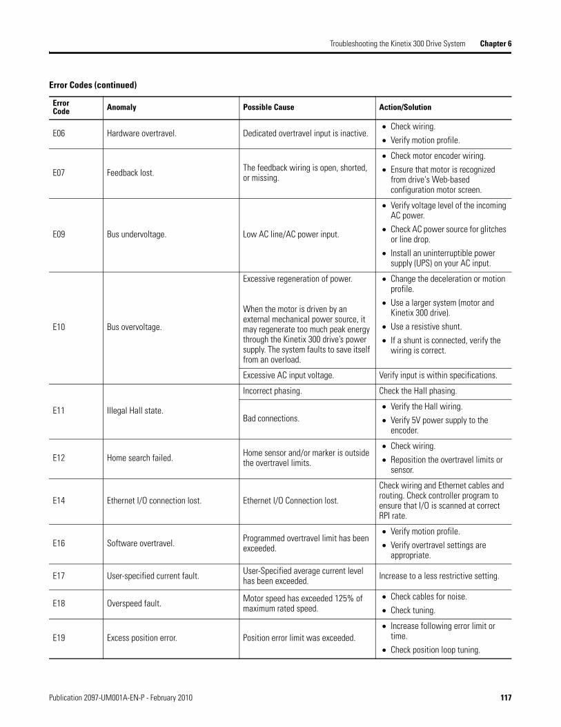
Troubleshooting the Kinetix 300 Drive System Chapter 6
E06 Hardware overtravel. Dedicated overtravel input is inactive. Check wiring.
Verify motion profile.
E07 Feedback lost. The feedback wiring is open, shorted, or missing.
Check motor encoder wiring.
Ensure that motor is recognized from drive's Web-based configuration motor screen.
E09 Bus undervoltage. Low AC line/AC power input.
Verify voltage level of the incoming AC power.
Check AC power source for glitches or line drop.
Install an uninterruptible power supply (UPS) on your AC input.
E10 Bus overvoltage.
Excessive regeneration of power.
When the motor is driven by an external mechanical power source, it may regenerate too much peak energy through the Kinetix 300 drive’s power supply. The system faults to save itself from an overload.
Change the deceleration or motion profile.
Use a larger system (motor and Kinetix 300 drive).
Use a resistive shunt.
If a shunt is connected, verify the wiring is correct.
Excessive AC input voltage. Verify input is within specifications.
E11 Illegal Hall state.
Incorrect phasing. Check the Hall phasing.
Bad connections. Verify the Hall wiring.
Verify 5V power supply to the encoder.
E12 Home search failed. Home sensor and/or marker is outside the overtravel limits.
Check wiring.
Reposition the overtravel limits or sensor.
E14 Ethernet I/O connection lost. Ethernet I/O Connection lost.
Check wiring and Ethernet cables and routing. Check controller program to ensure that I/O is scanned at correct RPI rate.
E16 Software overtravel. Programmed overtravel limit has been exceeded.
Verify motion profile.
Verify overtravel settings are appropriate.
E17 User-specified current fault. User-Specified average current level has been exceeded. Increase to a less restrictive setting.
E18 Overspeed fault. Motor speed has exceeded 125% of maximum rated speed.
Check cables for noise.
Check tuning.
E19 Excess position error. Position error limit was exceeded. Increase following error limit or
time.
Check position loop tuning.
Error Codes (continued)
ErrorCode Anomaly Possible Cause Action/Solution
Publication 2097-UM001A-EN-P - February 2010 117

Chapter 6 Troubleshooting the Kinetix 300 Drive System
E26 User-specified velocity fault. User specified velocity level was exceeded.
Increase to a less restrictive setting.
E30 Encoder communication fault. Communication was not established with an intelligent encoder.
Verify motor selection.
Verify the motor supports automatic identification.
Verify motor encoder wiring.
E31 Encoder data. Encoder data is corrupted. Replace the motor/encoder.
E37 Safe torque-off while enabled.The safety circuit was opened while drive was enabled or while attempting to enable.
Check safety circuit.
E43 Drive enable input.
An attempt was made to enable the axis through software while the Drive Enable hardware input was inactive.
Disable the Drive Enable Input fault.
The Drive Enable input transitioned from active to inactive while the axis was enabled.
Verify that Drive Enable hardware input is active whenever the drive is enabled through software.
E44 Controller changed to PROG mode. Program downloaded or turned key on logix controller to program position.
Place controller back in RUN mode, clear faults.
E67 Operating system failed. Hardware or configuration failure.
Cycle power.
Check configuration settings to ensure that drive tags setting are valid.
E70 Memory module error. Bad memory module Replace memory module
E72 Drive temperature too high.Improper airflow/environmental temperature exceeds specifications or an application anomaly.
Check for clogged vents or defective fan. Make sure cooling is not restricted by insufficient space around the unit. Check ambient temperature in enclosure. Reduce acceleration rates. Reduce duty cycle (ON/OFF) of commanded motion. Increase time permitted for motion.
Error Codes (continued)
ErrorCode Anomaly Possible Cause Action/Solution
118 Publication 2097-UM001A-EN-P - February 2010

Troubleshooting the Kinetix 300 Drive System Chapter 6
E74 Drive has exceeded peak current limit. Drive cannot regulate current properly.
Motor cables shorted. Verify continuity of motor power cables and connector.
Motor winding shorted internally.
Disconnect motor power cables form the motor. If the motor is difficult to turn by hand, it may need to be replaced.
The machine duty cycle requires an RMS current exceeding the continuous rating of the controller.
Change the command profile to reduce speed or increase time.
Operation above continuous power rating and/or product environmental rating.
Verify ambient temperature is not too high.
Operate within the continuous power rating.
Reduces acceleration rates.
The Kinetix 300 drive has a short circuit overcurrent, or failed component.
Remove all power and motor connections and preform a continuity check form the DC bus to the U, V, and W motor outputs. If a continuity exists, check for wire fibers between terminal or send drive in for repair.
E91 User watchdog has timed out. Ladder program error.
Not writing to WatchDogKick Tag frequently enough to prevent timeout.
Watchdog timout period set to too low a value. Increase timout period or change controller application to kick watchdog more frequently.
E92 Bad battery. Tamagawa absolute feedback battery voltage low or missing. Replace battery.
E93Motion setup parameters calculate an acceleration value above or below the drive capability.
Check indexing profiles or motion set up profiles.
Increase or decrease acceleration profile. Increase or decrease permitted time for motion.
E94 Motor or motor feedback cable.
Motor or feedback device malfunction. Check motor power/feedback
wiring.
Replace motor or encoder.
Recommenced grounding, per installation instructions, has not been followed.
Verify grounding.
Route feedback cables away from noise sources.
Refer to System Design for Control of Electric Noise Reference Manual, publication GMC-RM001.
Error Codes (continued)
ErrorCode Anomaly Possible Cause Action/Solution
Publication 2097-UM001A-EN-P - February 2010 119

Chapter 6 Troubleshooting the Kinetix 300 Drive System
Clearing Faults This section shows you how to clear the faults in the Kinetix 300 drive. There are a two methods to clear faults using digital input or drive parameters.
Clearing Faults Using Digital Inputs
There is a digital input, Fault Reset, on the Kinetix 300 drive that you can configure through the MotionView software. To clear faults using this input make the input active until the fault clears and then deactivate it.
Clearing Faults Using Drive Parameters
You can use the Kinetix 300 drive parameter to reset faults using Explicit Message or UserDefinedData.
Explicit Message
Send Explicit Message from within the RSLogix 5000 software to Class 374 (hex) Instance 53, Attribute 0 to set it to a 1 and then back to a 0 when the fault is cleared.
120 Publication 2097-UM001A-EN-P - February 2010

Troubleshooting the Kinetix 300 Drive System Chapter 6
UserDefinedData
Drive parameter used in the Explicit Message section can be mapped into the integer UserDefinedData by using the MotionView software. Then the parameter can be toggled by using the UserDefinedIntegerData0 or UserDefinedIntegerData1 tags within RSLogix 5000 software.
Drive Enable
The drive clears runtime faults if the drive enable command from RSLogix 5000 software is cycled and the fault reset in the MotionView software is configured for On Disable. For the drive to be enabled the DriveEn bit in the Output Assembly needs to be set to a 1. By changing that from a 1 back to a 0 the fault clears as the drive disables.
Publication 2097-UM001A-EN-P - February 2010 121

Chapter 6 Troubleshooting the Kinetix 300 Drive System
Notes:
122 Publication 2097-UM001A-EN-P - February 2010
Appendix A
Specifications and Dimensions
Introduction This appendix provides product specifications and mounting dimensions for your Kinetix 300 drive system components.
Topic Page
Introduction 123
Kinetix 300 Drive Power Specifications 124
Circuit Breaker/Fuse Specifications 127
Power Dissipation Specifications 129
General Specifications 129
AC Line Filter Specifications 132
Shunt Resistor Specifications 133
Product Dimensions 134
Publication 2097-UM001A-EN-P - February 2010 123

Appendix A Specifications and Dimensions
Kinetix 300 Drive Power Specifications
This section contains power specifications for your Kinetix 300 drive system components.
The 2097-V31PRx drives are capable of driving 240V motors at full speed.
Kinetix 300 Drive (single-phase) Power Specifications
Attribute 2097-V31PR0 2097-V31PR2 2097-V32PR0 2097-V32PR2 2097-V32PR4
AC input voltage 120/240V rms single-phase 240V rms single-phase
AC input frequency 48…62 Hz
Main AC input current (1)
Nom (rms) 120V inputMax inrush (0-pk) 120V inputNom (rms) 240V inputMax inrush (0-pk) 240V input
9.7 A2.3 A5.0 A1.1 A
16.8 A2.3A8.6 A1.1 A
5.0 A136 A
8.6 A2.3 A
15.0 A2.3 A
Integrated AC line filter No No Yes Yes Yes
Control power backup input voltage 20…26V DC
Control power backup input currentNomMax inrush (0-pk)
500 mA30 A
Continuous output current (rms) 2.0 A 4.0 A 2.0 A 4.0 A 8.0 A
Continuous output current (0-pk) 2.8 A 5.7 A 2.8 A 5.7 A 11.3 A
Peak output current (rms) (2) 6.0 A 12.0 A 6.0 A 12.0 A 24.0 A
Peak output current (0-pk) 8.5 A 17.0 A 8.5 A 17.0 A 39.9 A
Continuous power output 0.40 kW 0.80 kW 0.40 kW 0.80 kW 1.70 kW
Shunt On 390V DC 780V DC
Shunt Off 375V DC 750V DC
Overvoltage 430V DC 850V DC
Short circuit current rating 100,000 A (rms) symmetrical
(1) Kinetix 300 drive modules are limited to 1 AC mains power cycling per minute.
(2) Peak RMS current allowed for up to 2 seconds with a 50% duty cycle.
124 Publication 2097-UM001A-EN-P - February 2010

Specifications and Dimensions Appendix A
Kinetix 300 Drive (single-phase and three-phase) Power Specifications
Attribute 2097-V33PR1 2097-V33PR3 2097-V33PR5 2097-V33PR6
AC input voltage 120/240V rms single-phase or three-phase
AC input frequency 48…62 Hz
Main AC input current (1)
Nom (rms) 120V inputMax inrush (0-pk) 120V inputNom (rms) 240V inputMax inrush (0-pk) 240V input
5.0 A136 A3.0A136 A
8.6 A2.3 A5.0A2.3 A
15.0 A2.3 A8.7A2.3 A
24.0 A11.3 A13.9 A11.3 A
Integrated AC line filter No No No No
Control power backup input voltage 20…26V DC
Control power backup input currentNomMax inrush (0-pk)
500 mA30 A
Continuous output current (rms) 2.0 A 4.0 A 8.0 A 12.0 A
Continuous output current (0-pk) 2.8 A 5.7 A 11.3 A 17.0 A
Peak output current (rms) (2) 6 A 12 A 24 A 36 A
Peak output current (0-pk) 8.5 A 17.0 A 33.9 A 50.9 A
Continuous power output 0.50 kW 1.00 kW 2.00 kW 3.00 kW
Shunt On 390 V DC
Shunt Off 375V DC
Overvoltage 430V DC
Short circuit current rating 100,000 A (rms) symmetrical
(1) Kinetix 300 drive modules are limited to 1 AC mains power cycling per minute.
(2) Peak RMS current allowed for up to 2 seconds with a 50% duty cycle.
Publication 2097-UM001A-EN-P - February 2010 125

Appendix A Specifications and Dimensions
Kinetix 300 Drive (three-phase) Power Specifications
Attribute 2097-V34PR3 2097-V34PR5 2097-V34PR6
AC input voltage 480V rms three-phase
AC input frequency 48…62 Hz
Main AC input current (1)
Nom (rms)Max inrush (0-pk)
(1) Kinetix 300 drive modules are limited to 1 AC mains power cycling per minute.
2.7A4.5 A
5.5 A4.5 A
7.9 A22.6 A
Integrated AC line filter No No No
Control power backup input voltage 20…26V DC
Control power backup input currentNomMax inrush (0-pk)
500 mA30 A
Continuous output current (rms) 2.0 A 4.0 A 6.0 A
Continuous output current (0-pk) 2.8 A 5.7 A 8.5 A
Peak output current (rms) (2)
(2) Peak RMS current allowed for up to 2 seconds with a 50% duty cycle.
6 A 12 A 18 A
Peak output current (0-pk) 8.5 A 17.0 A 25.5 A
Continuous power output 1.00 kW 2.00 kW 3.00 kW
Shunt On 780V DC
Shunt Off 750V DC
Overvoltage 850V DC
Short circuit current rating 100,000 A (rms) symmetrical
126 Publication 2097-UM001A-EN-P - February 2010

Specifications and Dimensions Appendix A
Circuit Breaker/Fuse Specifications
While circuit breakers offer some convenience, there are limitations for their use. Circuit breakers do not handle high current inrush as well as fuses.
Make sure the selected components are properly coordinated and meet acceptable codes including any requirements for branch circuit protection. Evaluation of the short-circuit available current is critical and must be kept below the short-circuit current rating of the circuit breaker.
Use class CC or T fast-acting current-limiting type fuses, 200,000 AIC, preferred. Use Bussman KTK-R, JJN, JJS or equivalent. Thermal-magnetic type breakers preferred. The following fuse examples and Allen-Bradley circuit breakers are recommended for use with Kinetix 300 drives.
Fusing and Circuit Breakers
Cat. No.
Main VAC
Bussman FuseAllen-Bradley Circuit Breaker (1)
(1) When using Bulletin 1492 circuit protection devices, the maximum short circuit current
Disconnect(2)
(2) Use fully-rated short-circuit protection circuit breaker for device branch circuit protection only
Magnetic Contactor(3)
(3) Fully-rated breaker for overload current and short circuit rating.
2097-V31PR0
KTK-R-20 (20A) 1492-SP3D300 140M-F8T-C322097-V31PR2
2097-V32PR0
2097-V32PR2
2097-V32PR4 LPJ-45SP (45A) 1492-SP3D400 140M-F8E-C45
2097-V33PR1
KTK-R-20 (20A) 1492-SP3D300 140M-D8T-C202097-V33PR3
2097-V33PR5
2097-V33PR6 KTK-R-30 (30A) N/A 140U-F8T-C32
2097-V34PR3
KTK-R-20 (20A) 1492-SP3D400 140M-F8T-C322097-V34PR5
2097-V34PR6
Publication 2097-UM001A-EN-P - February 2010 127

Appendix A Specifications and Dimensions
Contactor Ratings
This table lists the recommended contactor ratings for the Kinetix 300 drive.
Contactor Rating
Transformer Specifications for Input Power
Kinetix 300 Drive (120/240V) Cat. No. Contactor
2097-V31PR0 100-C30x10 (AC coil)100-C30Zx10 (DC coil)2097-V31PR2
Kinetix 300 Drive (240V) Cat. No.
2097-V32PR0 100-C30x10 (AC coil)100-C30Zx10 (DC coil)2097-V32PR2
2097-V32PR4 100-C37x10 (AC coil)100-C23Zx10 (DC coil)
2097-V33PR1100-C23x10 (AC coil)100-C23Zx10 (DC coil)2097-V33PR3
2097-V33PR5
2097-V33PR6 100-C30x10 (AC coil)100-C30x10 (DC coil)
Kinetix 300 Drive (480V) Cat. No.
2097-V34PR3100-C37x10 (AC coil)100-C23Zx10 (DC coil)2097-V34PR5
2097-V34PR6
Attribute Value (460V system)
Input volt-amperes 750VA
Input voltage 460V AC
Output voltage 120…240V AC
128 Publication 2097-UM001A-EN-P - February 2010

Specifications and Dimensions Appendix A
Power Dissipation Specifications
Use the following table to size an enclosure and calculate required ventilation for your Kinetix 300 drive system.
General Specifications This section contains general specifications for your Kinetix 300 drive system components.
Maximum Feedback Cable Lengths
Although Bulletin 2090 motor feedback cables are available in standard lengths up to 90 m (295.3 ft), the maximum feedback cable length for connecting motors or actuators to a Kinetix 300 drive is 20 m (65.6 ft).
Cat. No. Power Dissipation, W
2097-V31PR0 28
2097-V31PR2 39
2097-V32PR0 28
2097-V32PR2 39
2097-V32PR4 67
2097-V33PR1 28
2097-V33PR3 39
2097-V33PR5 67
2097-V33PR6 117
2097-V34PR3 39
2097-V34PR5 58
2097-V34PR6 99
Publication 2097-UM001A-EN-P - February 2010 129

Appendix A Specifications and Dimensions
Kinetix 300 Drive Weight Specifications
Certifications
Kinetix 300 DriveCat. No.
Value, approx.kg (lb)
2097-V31PR0 1.3 (2.86)
2097-V31PR2 1.5 (3.31)
2097-V32PR0 1.4 (3.09)
2097-V32PR2 1.7 (3.75)
2097-V32PR4 2.2 (4.85)
2097-V33PR1 1.3 (2.86)
2097-V33PR3 1.5 (3.31)
2097-V33PR5 2.0 (4.41)
2097-V33PR6 1.9 (4.19)
2097-V34PR3 1.5 (3.31)
2097-V34PR5 2.0 (4.41)
2097-V34PR6 1.8 (3.97)
Certification (1)
(when product is marked)Standards
c-UL-us UL Listed to U.S. and Canadian safety standards (UL 508 C File E59272).
CE
European Union 2004/108/EC EMC Directive compliant with EN 61800-3:2004: Adjustable Speed Electrical Power Drive Systems - Part 3; EMC Product Standard including specific test methods.European Union 2006/95/EC Low Voltage Directive compliant with: EN 61800-5-1:2003 - Safety of Machinery - Electrical Equipment of Machines.
EN 50178:1997 - Electronic Equipment for use in Power Installations.
Functional Safety
EN 60204-1:1997 - Safety of Machinery - Electrical Equipment of Machines.
IEC 61508: Part 1-7:2000 - Functional Safety of Electrical/Electronic/Programmable Electronic Safety-related Systems.
EN954-1:1996 - Safety of machinery. Safety related parts of control systems. Part 1: General principles for design.
C-Tick
Radio communications Act: 1992
Radio communications (Electromagnetic Compatibility) Standard: 1998
Radio communications (Compliance Labelling - Incidental Emissions) Notice: 1998
AS/NZS CISPR 11: 2003 (Group 1, Class A)
(1) Refer to http://www.ab.com for Declarations of Conformity Certificates.
130 Publication 2097-UM001A-EN-P - February 2010

Specifications and Dimensions Appendix A
Environmental Specifications
Attribute Operating Range Storage Range (nonoperating)
Ambient temperature 0…40 C (32…104 F) -10…70 C (14…158F)
Relative humidity 5…95% noncondensing 5…95% noncondensing
Altitude De-rate by 1% per 300 m (1000 ft) above 1500 m (5000 ft) 3000 m (9843 ft) during transport
Vibration 5…2000 Hz @ 2.5 g peak, 0.015 mm (.0006 in.) max displacement
Shock 15 g, 11 ms half-sine pulse (3 pulses in each direction of 3 mutually perpendicular directions)
Publication 2097-UM001A-EN-P - February 2010 131

Appendix A Specifications and Dimensions
AC Line Filter Specifications
The tables below contain specifications for AC line filters available for Kinetix 300 servo drive systems.
AC Line Filter Specifications (catalog number 2097-Fx)
AC Line Filter Specifications (catalog number 2090-XXLF-TC116)
Attribute 2090-XXLF-TC116
Use with Kinetix 300 DriveCat. No.
2097-V31PR02097-V31PR2
Voltage 250V AC 50/60 Hz
Phase Single
Current A @ 50 °C (122°F) 16
Power loss W –
Leakage current mA 87
Weight, approx. kg (lb) 0.80 (1.7)
Humidity 90% relative humidity.
Vibration 10…200 Hz @ 1.8 g vibration.
Operating temperature -25…100 °C (-13…212 °F)
Attribute 2097-F1 2097-F2 2097-F4 2097-F5 2097-F6
Use with Kinetix 300 Drive Cat. No.(1) 2097-V33PR6 2097-V34PR6 2097-V33PR1 2097-V34PR3 2097-V34PR5 2097-V33PR3 2097-V33PR5
Voltage 120/240V AC50/60 Hz
480V AC50/60 Hz
120/240V AC50/60 Hz
480V AC50/60 Hz
120/240V AC50/60 Hz
Phase One or Three Three One or Three Three One or Three
Current A @ 40 °C (104 °F) 24 10 4.4 6.9 15.0
Power loss W 5.2 2.8 1.2 1.3 4.1
Leakage current mA 9 1
Weight, approx.kg (lb) 0.6 (1.3) 0.8 (1.8)
Humidity 5…95% noncondensing.
Vibration 5…2000 Hz @ 2.5 g peak, 0.015 mm (.0006 in.) maximum displacement.
Operating temperature 0…40 C (32…104 F)
(1) Kinetic 300 drives (catalog numbers 2097-V32PR0, 2097-V32PR2, and 2097-V32PR4) have integrated AC line filters.
132 Publication 2097-UM001A-EN-P - February 2010

Specifications and Dimensions Appendix A
Shunt Resistor Specifications
Bulletin 2097 passive shunt resistor wire to the Kinetix 300 drive.
Shunt Resistor Power Specifications
Attribute 2097-R2 2097-R3 2097-R4 2097-R6 2097-R7
Use with Kinetix 300 driveCat. No.
2097-V32PR42097-V33PR5 2097-V33PR6
2097-V31PR02097-V31PR22097-V32PR02097-V32PR22097-V33PR12097-V33PR3
2097-V34PR52097-V34PR6 2097-V34PR3
Resistor value 20 30 40 75 150
Peak power kW 7.6 5.1 3.8 7.9 4.0
Peak current A 19.5 13.0 9.8 10.3 5.1
Continuous power W 150 80 150 80
% RD_Application, max (1) 1.97 2.96 2.10 1.90 2.02
Weight, approx. kg (lb) 0.3 (0.7) 0.2 (0.4) 0.3 (0.7) 0.2 (0.4)
(1) RD_Application is the application duty cycle in percent. For the intermittent regeneration applications use RD_Application = t/T. Where t is the duration when regeneration is needed and T is the time interval between two regenerations. Both t and T must use the same time units such as seconds.
Publication 2097-UM001A-EN-P - February 2010 133
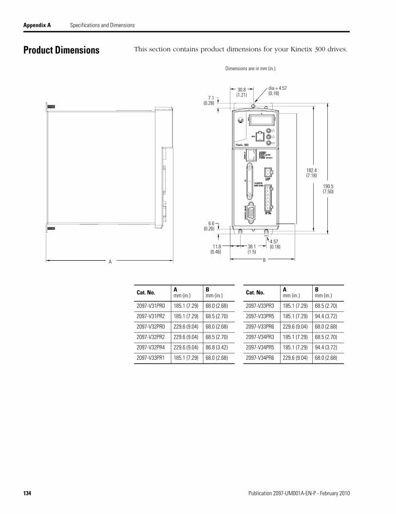
Appendix A Specifications and Dimensions
Product Dimensions This section contains product dimensions for your Kinetix 300 drives.
A
11.8(0.46)
6.6(0.26)
7.1(0.28)
B
38.1(1.5)
182.4(7.18)
190.5(7.50)
30.8(1.21)
dia = 4.57(0.18)
4.57(0.18)
Dimensions are in mm (in.).
Cat. No. Amm (in.)
Bmm (in.) Cat. No. A
mm (in.)Bmm (in.)
2097-V31PR0 185.1 (7.29) 68.0 (2.68) 2097-V33PR3 185.1 (7.29) 68.5 (2.70)
2097-V31PR2 185.1 (7.29) 68.5 (2.70) 2097-V33PR5 185.1 (7.29) 94.4 (3.72)
2097-V32PR0 229.6 (9.04) 68.0 (2.68) 2097-V33PR6 229.6 (9.04) 68.0 (2.68)
2097-V32PR2 229.6 (9.04) 68.5 (2.70) 2097-V34PR3 185.1 (7.29) 68.5 (2.70)
2097-V32PR4 229.6 (9.04) 86.8 (3.42) 2097-V34PR5 185.1 (7.29) 94.4 (3.72)
2097-V33PR1 185.1 (7.29) 68.0 (2.68) 2097-V34PR6 229.6 (9.04) 68.0 (2.68)
134 Publication 2097-UM001A-EN-P - February 2010

Appendix B
Interconnect Diagrams
Introduction This appendix provides wiring examples and system block diagrams for your Kinetix 300 drive system components.
Topic Page
Introduction 135
Wiring Examples 136
Publication 2097-UM001A-EN-P - February 2010 135
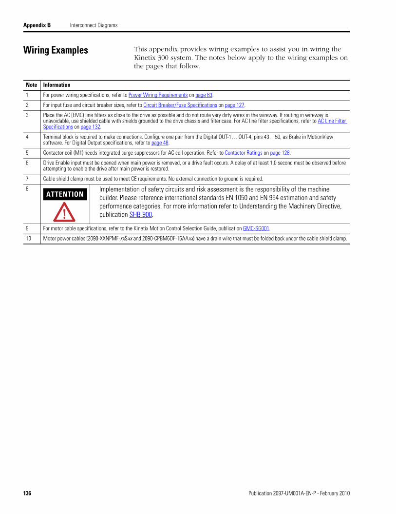
Appendix B Interconnect Diagrams
Wiring Examples This appendix provides wiring examples to assist you in wiring the Kinetix 300 system. The notes below apply to the wiring examples on the pages that follow.
Note Information
1 For power wiring specifications, refer to Power Wiring Requirements on page 63.
2 For input fuse and circuit breaker sizes, refer to Circuit Breaker/Fuse Specifications on page 127.
3 Place the AC (EMC) line filters as close to the drive as possible and do not route very dirty wires in the wireway. If routing in wireway is unavoidable, use shielded cable with shields grounded to the drive chassis and filter case. For AC line filter specifications, refer to AC Line Filter Specifications on page 132.
4 Terminal block is required to make connections. Configure one pair from the Digital OUT-1… OUT-4, pins 43…50, as Brake in MotionView software. For Digital Output specifications, refer to page 48.
5 Contactor coil (M1) needs integrated surge suppressors for AC coil operation. Refer to Contactor Ratings on page 128.
6 Drive Enable input must be opened when main power is removed, or a drive fault occurs. A delay of at least 1.0 second must be observed before attempting to enable the drive after main power is restored.
7 Cable shield clamp must be used to meet CE requirements. No external connection to ground is required.
8ATTENTION
Implementation of safety circuits and risk assessment is the responsibility of the machine builder. Please reference international standards EN 1050 and EN 954 estimation and safety performance categories. For more information refer to Understanding the Machinery Directive, publication SHB-900.
9 For motor cable specifications, refer to the Kinetix Motion Control Selection Guide, publication GMC-SG001.
10 Motor power cables (2090-XXNPMF-xxSxx and 2090-CPBM6DF-16AAxx) have a drain wire that must be folded back under the cable shield clamp.
136 Publication 2097-UM001A-EN-P - February 2010

Interconnect Diagrams Appendix B
Power Wiring Examples
You must supply input power components. The single-phase and three-phase line filters are wired downstream of fusing and the M1 contactor.
Kinetix 300 Drive Wiring Example (120V single-phase input power)
PE
L1
L2/N
+24V DC
Com
B+B+BRB-B-
EN
ACOM
RDY +
RDY -
L1
L2/N
29
26
41
42
1
3
4
U
V
W
PE
Single-phase AC Input120V rms AC, 50/60 Hz
Notes 1, 2
IsolationTransformer *
Bonded Cabinet Ground Bus *Ground Stud
MainsSingle-phaseInput (IPD)Connector
Fuse Disconnector Circuit Breakers
Input Fusing *
M1 *Notes 5, 6
Use discrete logic or PLC to control
ENABLE to drive and monitor RDY signal
back from drive.
Refer to Attention statement (Note 8).
Shunt Resistor and DC Bus (BC)
Connector
Three-phaseMotor PowerConnectionsNote 9
Motor Power (MP) Connector
Cable ShieldClampNote 7
I/O (IOD) Connector
To Shunt Resistor
Back-up Power (BP) Connector
User supplied+24V DC
ToMotor
2097-V31PRx and 2097-V33PRx
Kinetix 300 Drive
* Indicates User Supplied Component
Refer to table on page 136 for note information.
AC Line FilterCatalog Number
2090-XXLF-TC116
(Optional)
Publication 2097-UM001A-EN-P - February 2010 137

Appendix B Interconnect Diagrams
Kinetix 300 Drive Wiring Example (240V single-phase input power)
PE
L1
L2/N
+24V DC
Com
B+B+BRB-B-
EN
ACOM
RDY +
RDY -
L1
L2/N
29
26
41
42
U
V
W
PE
Single-phase AC Input240V AC RMS, 50/60 Hz
Notes 1, 2
IsolationTransformer *
Bonded Cabinet Ground Bus *Ground Stud
MainsSingle-phaseInput (IPD)Connector
Fuse Disconnector Circuit Breakers
Input Fusing *
M1 *Notes 5, 6
Use discrete logic or PLC to control
ENABLE to drive and monitor RDY signal
back from drive.
Refer to Attention statement (Note 8).
Shunt Resistor and DC Bus (BC)
Connector
Three-phaseMotor PowerConnectionsNote 9
Motor Power (MP) Connector
Cable ShieldClampNote 7
I/O (IOD) Connector
To Shunt Resistor
Back-up Power (BP) Connector
User supplied+24V DC
ToMotor
2097-V31PRx and 2097-V33PRx
Kinetix 300 Drive
* Indicates User Supplied Component
Refer to table on page 136 for note information.
Bulletin2097AC Line Filter
(Optional)
138 Publication 2097-UM001A-EN-P - February 2010

Interconnect Diagrams Appendix B
Kinetix 300 Drive Wiring Example (240/480V three-phase input power)
PE
L1
L2
L3
+24V DC
Com
B+B+BRB-B-
L1
L2
L3
M1
1
2
3
4
U
V
W
PE
PE
L1
L2
L3
EN
ACOM
RDY +
RDY -
29
26
41
42
Three-phase AC Input240/480V rms AC, 50/60 HzNotes 1, 2
IsolationTransformer *
Bonded Cabinet Ground Bus * Ground Stud
MainsSingle-phaseInput (IPD)Connector
Fuse Disconnector Circuit Breakers
Input Fusing *
M1 *Notes 5, 6
Refer to Attention statement (Note 8).
Shunt Resistor and DC Bus (BC)
Connector
Three-phaseMotor PowerConnectionsNote 9
Motor Power (MP) Connector
Cable ShieldClampNote 7
I/O (IOD)Connector
To Shunt Resistor
Back-up Power (BP) Connector
User supplied+24V DC
ToMotor
2097-V33PRx and 2097-V34PRx
Kinetix 300 Drives
* Indicates User Supplied Component
Refer to table on page 136 for note information.
AC Line Filter(optional)
Note 3
Bonded Cabinet Ground Bus
Chassis
Three Phase 230V or 460V rms AC
Neutral
Use discrete logic or PLC to control ENABLE
to drive and monitor RDY signal back from
drive.
IMPORTANT For the 480V Kinetix 300 drives to meet ISO 13849-1 Safety Category 3 Performance Level d spacing requirements, each phase voltage to ground must be less than or equal to 300V AC rms. This means that the power system must use center grounded wye secondary configuration for 400/480V AC mains.
Publication 2097-UM001A-EN-P - February 2010 139

Appendix B Interconnect Diagrams
Shunt Resistor Wiring Example
Refer to the Shunt Resistor Specifications on page 133, for the Bulletin 2097-Rx shunt resistors that are available for the Kinetix 300 drives.
Refer to the Kinetix 300 Shunt Resistor Installation Instructions, publication 2097-IN002, for additional installation information.
Shunt Resistor Wiring Example
B+B+BRB-B-
12345
2097-V3xPRxKinetix 300 Drive
2097-RxShunt
Resistor
Brake/DC Bus (BC)
Connector
140 Publication 2097-UM001A-EN-P - February 2010

Interconnect Diagrams Appendix B
Kinetix 300 Drive/Rotary Motor Wiring Examples
Kinetix 300 Drive Wiring Example with MP-Series (Bulletin MPL-A/B, MPM-A/B, MPF-A/B, and MPS-A/B) Motors
D/
C/WB/V
A/U
BR-
BR+
G/-
F/+
W
V
U
0123456789
101112131415
SIN+SIN-COS+COS-
DATA+DATA-+5VDCECOM
GREENWHT/GREEN
GRAYWHT/GRAY
BLACKWHT/BLACK
REDWHT/RED
34
56
12
910
12
34
510146
14
12
+9VDCTS+
ORANGEWHT/ORANGE
1113
711
4321
Green/Yellow
Blue
Black
Brown
GND
BR+
BR-
F
G
W
V
U
GND
Shield
WVU
D
CB
A
TS-
COM
BLUE
AM+AM-BM+BM-
IM+IM-
+5VDCECOM
BLUEWHT/BLUE
GREENWHT/GREEN
GRAYWHT/GRAY
BLACKWHT/BLACK
REDWHT/RED
12
34
510146
12TS-S1
–TS+
ORANGEWHT/ORANGE 11
S2S3
COM
YELLOWWHT/YELLOW
138
34
56
12
1415161712
1113
910
Black
White
CR1
OUT4-EOUT4-C
24V DC24V DC COM
Motor Brake
I/O (IOD) Connector
Note 4
Motor Power (MP) Connector
2097-V3xPRxKinetix 300 Drive
MPL-A/Bxxx, MPM-A/BxxxMPF-A/Bxxx, and MPS-A/Bxxx
Servo Motors withHigh Resolution Feedback
Motor Feedback(MF) Connector
Three-phaseMotor Power
Motor Feedback
Thermostat
User Supplied24V DC
Three-phaseMotor Power
Motor Feedback
Thermostat
MPL-A/B15xx and MPL-A/B2xxMPL-A3xx…MPL-A45xx
MPL-A/B15xx...MPL-A/B45xxServo Motors with
Incremental Feedback2090-K2CK-D15M
Connector Kit
2090-K2CK-D15MConnector Kit
Motor Brake
Refer to low profile connectorillustration (lower left)
for proper grounding technique.
Refer to low profile connector illustration (lower left)
for proper grounding technique.
Low Profile Connector(2090-K2CK-D15M shown)
Grounding Technique forFeedback Cable Shield
Turn clamp over to holdsmall cables secure.
Exposed shield secured under clamp.
Clamp Screws (2)
Clamp
Refer to table on page 136 for note information.
2090-XXNFMF-Sxx (standard) or2090-CFBMxDF-CDAFxx (continuous-flex)
(flying-lead) Feedback CableNote 9
2090-XXNFMF-Sxx (non-flex) or2090-CFBMxDF-CDAFxx (continuous-flex)
(flying-lead) Feedback CableNote 9
2090-XXNPMF-xxSxx (standard)or 2090-CPBMxDF-xxAFxx
(continuous-flex)Motor Power Cable
Note 9Use 2090-CPWMxDF-xxAFxx
cable for continuous flex non-brake applications.
Cable ShieldClampNote 7
Publication 2097-UM001A-EN-P - February 2010 141
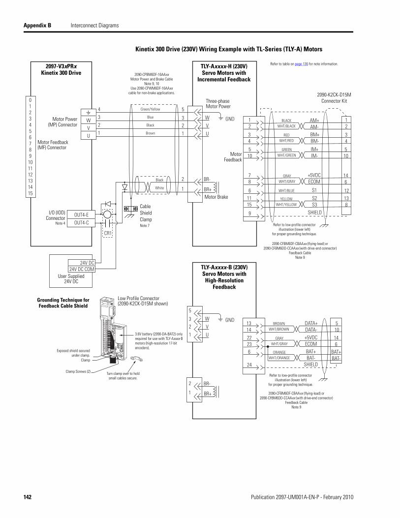
Appendix B Interconnect Diagrams
Kinetix 300 Drive (230V) Wiring Example with TL-Series (TLY-A) Motors
5
32
1
BR+
BR-
1
2
W
V
U
GND
0123456789101112131415
4321
Green/Yellow
Blue
Black
Brown
Black
White
WVU
AM+AM-BM+BM-
IM+IM-
+5VDCECOM
WHT/BLUE
GREENWHT/GREEN
GRAYWHT/GRAY
BLACKWHT/BLACK
REDWHT/RED
12
34
510
146
12S1
S2S3
YELLOWWHT/YELLOW
138
SHIELD
78
6
9
1115
12
34
510
5
32
1
BR+
BR-
1
2
W
V
U +5VDCECOM
GRAYWHT/GRAY
2223
146
24
GND
SHIELD
BAT+BAT-
ORANGEWHT/ORANGE
6 BAT+BAT-
DATA+DATA-
BROWNWHT/BROWN
1314
510
CR1
OUT4-EOUT4-C
24V DC24V DC COM
Motor Brake
Three-phaseMotor Power
Motor Feedback
TLY-Axxxx-H (230V)Servo Motors with
Incremental Feedback
2090-K2CK-D15M Connector Kit
2090-CFBM6DF-CBAAxx (flying-lead) or 2090-CFBM6DD-CCAAxx (with drive-end connector)
Feedback CableNote 9
I/O (IOD) Connector
Note 4
Motor Power (MP) Connector
2097-V3xPRxKinetix 300 Drive
Motor Feedback(MF) Connector
2090-CPBM6DF-16AAxxMotor Power and Brake Cable
Note 9, 10Use 2090-CPWM6DF-16AAxx
cable for non-brake applications.
User Supplied24V DC
Refer to low-profile connectorillustration (lower left)
for proper grounding technique.
Low Profile Connector(2090-K2CK-D15M shown)
Grounding Technique forFeedback Cable Shield
Turn clamp over to holdsmall cables secure.
Exposed shield secured under clamp.
Clamp Screws (2)
Refer to table on page 136 for note information.
TLY-Axxxx-B (230V)Servo Motors with
High-Resolution Feedback
Cable ShieldClampNote 7
3.6V battery (2090-DA-BAT2) onlyrequired for use with TLY-Axxxx-B motors (high-resolution 17-bit encoders).
Clamp
2090-CFBM6DF-CBAAxx (flying-lead) or 2090-CFBM6DD-CCAAxx (with drive-end connector)
Feedback CableNote 9
Refer to low-profile connectorillustration (lower left)
for proper grounding technique.
142 Publication 2097-UM001A-EN-P - February 2010
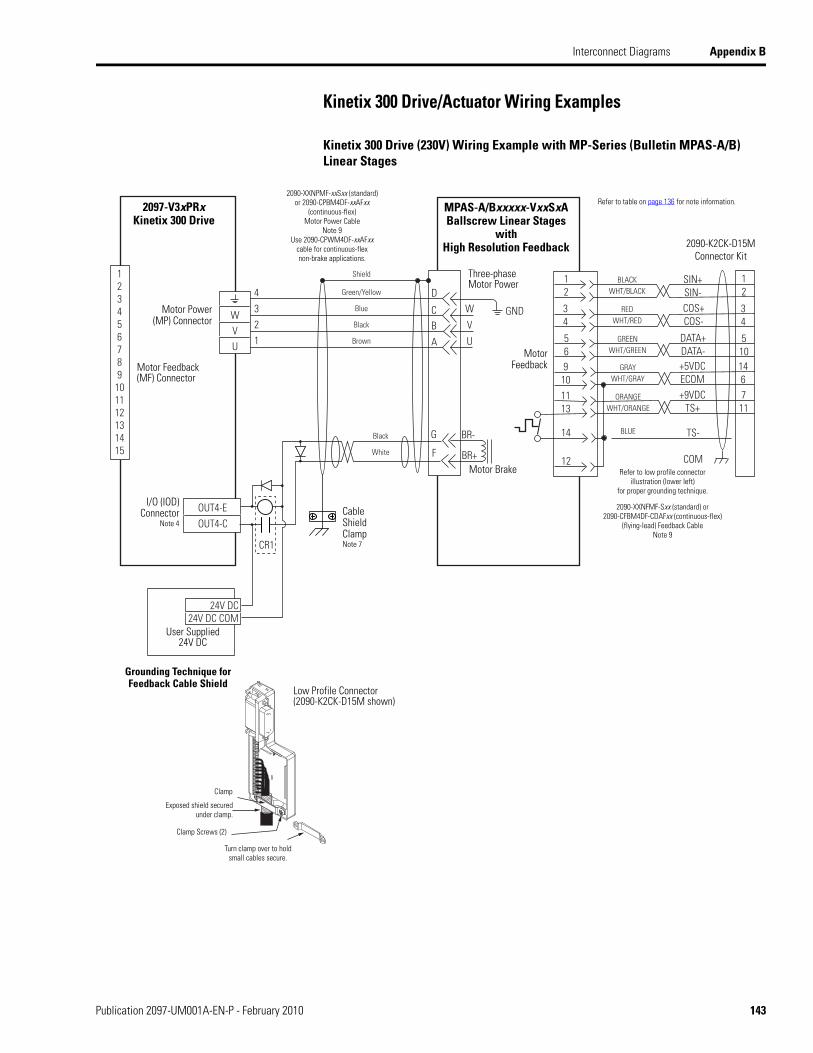
Interconnect Diagrams Appendix B
Kinetix 300 Drive/Actuator Wiring Examples
Kinetix 300 Drive (230V) Wiring Example with MP-Series (Bulletin MPAS-A/B) Linear Stages
D
CB
A
BR+
BR-
F
G
W
V
U
SIN+SIN-COS+COS-
DATA+DATA-+5VDCECOM
GREENWHT/GREEN
GRAYWHT/GRAY
BLACKWHT/BLACK
REDWHT/RED
34
56
12
910
12
34
510146
14
12
+9VDCTS+
ORANGEWHT/ORANGE
1113
711
4321
Green/Yellow
Blue
Black
Brown
Black
White
GND
Shield
WVU
TS-
COM
BLUE
123456789
101112131415
CR1
OUT4-EOUT4-C
24V DC24V DC COM
MPAS-A/Bxxxxx-VxxSxA Ballscrew Linear Stages
withHigh Resolution Feedback
Motor Brake
Three-phaseMotor Power
Motor Feedback
2090-K2CK-D15M Connector Kit
I/O (IOD) Connector
Note 4
Motor Power (MP) Connector
2097-V3xPRxKinetix 300 Drive
Motor Feedback(MF) Connector
User Supplied24V DC
Low Profile Connector(2090-K2CK-D15M shown)
Grounding Technique forFeedback Cable Shield
Turn clamp over to holdsmall cables secure.
Exposed shield secured under clamp.
Clamp Screws (2)
Clamp
Refer to table on page 136 for note information.2090-XXNPMF-xxSxx (standard)
or 2090-CPBM4DF-xxAFxx (continuous-flex)
Motor Power CableNote 9
Use 2090-CPWM4DF-xxAFxxcable for continuous-flex non-brake applications.
Refer to low profile connectorillustration (lower left)
for proper grounding technique.
2090-XXNFMF-Sxx (standard) or2090-CFBM4DF-CDAFxx (continuous-flex)
(flying-lead) Feedback CableNote 9
Cable ShieldClampNote 7
Publication 2097-UM001A-EN-P - February 2010 143

Appendix B Interconnect Diagrams
Kinetix 300 Drive Wiring Example with MP-Series Electric Cylinders
D
CB
A
BR+
BR-
F
G
W
V
U
34
56
12
910
1412
1113
GND
SIN+SIN-COS+COS-
DATA+DATA-
GREENWHT/GREEN
GRAYWHT/GRAY
BLACKWHT/BLACK
REDWHT/RED
12
34
510146
+9VDCTS+
ORANGEWHT/ORANGE
711
+5VDCECOM
TS-COM
BLUE
0123456789101112131415
4321
Green/Yellow
Blue
Black
Brown
Shield
WVU
CR1
OUT4-EOUT4-C
24V DC24V DC COM
Motor Brake
Motor Power (MP) Connector
MPAR-A/Bxxxxx-xxx and MPAI-A/Bxxx
Electric Cylinder with High Resolution Feedback
Motor Feedback(MF) Connector
Three-phaseMotor Power
Motor Feedback
Thermostat
User Supplied24V DC
2090-K2CK-D15M Connector Kit
Refer to low profile connectorillustration below
for proper grounding technique.
Low Profile Connector(2090-K2CK-D15M shown)
Grounding Technique forFeedback Cable Shield
Turn clamp over to holdsmall cables secure.
Exposed shield secured under clamp.
Clamp Screws (2)
Clamp
2097-V3xPRxKinetix 300 Drive
2090-XXNFMF-Sxx (standard) or2090-CFBMxDF-CDAFxx (continuous-flex)
(flying-lead) Feedback CableNote 9
2090-XXNPMF-16Sxx (standard)or 2090-CPBMxDF-16AFxx
(continuous-flex)Motor Power Cable
Note 9Use 2090-CPWMxDF-16AFxx
cable for continuous-flex non-brake applications.
I/O (IOD) Connector
Note 4Cable ShieldClampNote 7
MP-Series Electric Cylinder Power and Feedback Cables
MP-Series Electric CylinderCat. No. Fr
ame Power Cable
Cat. No.Feedback CableCat. No.
MPAR-A/B1xxx 322090-CPxM4DF-16AFxx
2090-XXNFMF-Sxx (standard)2090-CFxM4DF-16AFxx(continuous-flex)MPAR-A/B2xxx 40
MPAR-A/B3xxx 63
2090-CPxM7DF-16AFxx2090-XXNFMF-Sxx (standard)2090-CFxM7DF-16AFxx(continuous-flex)MPAI-A/Bxxx
83
110
144 Publication 2097-UM001A-EN-P - February 2010

Interconnect Diagrams Appendix B
Kinetix 300 Drive (230V) Wiring Example with TL-Series (TLAR) Electric Cylinders
5
32
1
BR+
BR-
1
2
W
V
U
GND
0123456789
101112131415
4321
Green/Yellow
Blue
Black
Brown
Black
White
WVU
+5VDCECOM
GRAYWHT/GRAY
2223
146
24 SHIELD
BAT+BAT-
ORANGEWHT/ORANGE
6 BAT+BAT-
DATA+DATA-
BROWNWHT/BROWN
1314
510
CR1
OUT4-EOUT4-C
24V DC24V DC COM
Motor Brake
Three-phaseMotor Power
Motor Feedback
TLAR-Axxxx (230V)Servo Motors with
High Resolution Feedback
2090-K2CK-D15M Connector Kit
2090-CFBM6DF-CBAAxx (flying-lead) or 2090-CFBM6DD-CCAAxx (with drive-end connector)
Feedback CableNote 9
I/O (IOD) Connector
Note 4
Motor Power (MP) Connector
2097-V3xPRxKinetix 300 Drive
Motor Feedback(MF) Connector
2090-CPBM6DF-16AAxxMotor Power and Brake Cable
Note 9, 10Use 2090-CPWM6DF-16AAxx
cable for non-brake applications.
User Supplied24V DC
Refer to low-profile connectorillustration (lower left)
for proper grounding technique.
Low Profile Connector(2090-K2CK-D15M shown)
Grounding Technique forFeedback Cable Shield
Turn clamp over to holdsmall cables secure.
Exposed shield secured under clamp.
Clamp Screws (2)
Clamp
Refer to table on page 136 for note information.
3.6V battery (2090-DA-BAT2) onlyrequired for use with TLY-Axxxx-B motors(high-resolution 17-bit encoders).
Cable ShieldClampNote 7
Publication 2097-UM001A-EN-P - February 2010 145

Appendix B Interconnect Diagrams
Kinetix 300 Drive/Micrologix Controller Wiring Examples
The Kinetix 300 drive accepts unipolar or bipolar inputs.
Kinetix 300 Drive Wiring Example to MicroLogix Controller Analog Velocity (or Current) Control Mode
Kinetix 300 Drive Wiring Example to MicroLogix Controller Step and Direction
4
3 O5
Chassis
COM
23
22
25
24
DIRECTION +
DIRECTION-
ACOM
AIN+
AIN+
AOUT
COM
IV1
OV1
Digital
2097-V3xPRxKinetix 300 Drive
I/O (IOD) Connector
Analog
MiroLogix 1400 Controller
1766-L32BXB1766-L32BXBA
4
3
2
1 O2
COM
O5
Chassis
Direction +
Direction -
Step -
Step +
2097-V3xPRxKinetix 300 Drive
MiroLogix 1400 Controller
1766-L32BXB1766-L32BXBA
I/O (IOD) Connector
146 Publication 2097-UM001A-EN-P - February 2010

Interconnect Diagrams Appendix B
Kinetix 300 Drive Master Gearing Wiring Example
GND
BA+BA-BB+BB-
MA+MA-MB+MB-
GND5
789
10
1234
5
2097-V3xPRxKinetix 300 Drive
(Master)
2097-V3xPRxKinetix 300 Drive
(Slave)
Motor Feedback
(MF) Connector
Master EncoderInputs
MotorFeedback(MF) Connector
Buffered Encoder Outputs
I/O (IOD) Connector
Bulletin MPL or Bulletin TLYIncremental Feedback Motor
Bulletin MPL or Bulletin TLYIncremental Feedback Motor
I/O (IOD) Connector
Publication 2097-UM001A-EN-P - February 2010 147

Appendix B Interconnect Diagrams
Motor Brake Currents
The motor brake currents are listed in the following tables. Use these values to size the 24V DC transformer required for your application.
Coil Currents Rated at < 1.0 A
Compatible Brake Motors/Actuators (1)
(1) Use of the variable x indicates this specification applies to 230V and 460V motors.
Coil Current
MPL-x1510, MPL-x1520, MPL-x1530 0.43…0.53 A
MPL-x210, MPL-x220, MPL-x230 0.46…0.56 A
MPL/MPF-x310, MPL/MPF-x320, MPL/MPF-x3300.45…0.55 A
MPS-x330
MPL-x420, MPL-x430, MPL-x4520, MPL-x4530, MPL-x4540, MPL-B4560
0.576…0.704 AMPF-x430, MPF-x4530, MPF-x4540
MPS-x4540
TLY-A110T, TLY-A120T, and TLY-A130T 0.18…0.22 A
TLY-A220T and TLY-A230T 0.333…0.407 A
TLY-A2530P, TLY-A2540P, and TLY-A310M 0.351…0.429 A
148 Publication 2097-UM001A-EN-P - February 2010

Appendix C
Input and Output Assembly
Introduction This section describes the input and output assembly used to communicate with RSlogix 5000 software.
About the Input and Output Assembly
The terms Input and Output refer to the point of view of the scanner device. Output data is produced by the scanner and consumed by the adapter. Input data is produced by the adapter and consumed by the scanner. The Kinetix 300 drive is an adapter device, the controller using RSLogix 5000 software is a scanner device.
The drive contains EtherNet/IP Assembly Object Instances that pertain to the following RSLogix 5000 connection parameters:
Input (actual values such as actual velocity, actual position)
Output (enable and reference value going to the drive)
Index Configuration (see Appendix E on page 167).
Assembly instances are accessible using Class 3 explicit messages as well as the Class 1 I/O messaging.
Topic Page
Introduction 149
About the Input and Output Assembly 149
Input and Output Assembly 150
Publication 2097-UM001A-EN-P - February 2010 149

Appendix C Input and Output Assembly
Kinetix 300 drive parameters are modifiable using Explicit Messaging. The system object to which the Explicit Messages is directed to is described in the following table.
When a Kinetix 300 drive parameter is changed using Explicit Messaging, the Set Attribute Single message instruction is directed at this class, the instance is the identifier of the actual parameter and the attribute depends upon the type of data being written.
Input and Output Assembly
Kinetix 300 Drive Object
Attribute Value Comment
Service type Get Attribute Single Service code 0x0E (hex)
Set Attribute Single Service code 0x10 (hex)
Class 374 Hex
Instance ID tag from Appendix F –
Attribute 0 DINT, RAM
1 DINT, MEM
2 REAL, RAM
3 REAL, MEM
4 String, RAM
5 String, MEM
IMPORTANT If power is removed from the drive data is stored in RAM is lost. Data stored in the memory module remains through power cycles.
IMPORTANT Memory Module writes are limited to 1,000,000 per device. Ensure that all writes targeted at the Memory Module are necessary and not done as part of a background or cyclic task.
Input Assembly
RSLogix 5000 Field Description
Fault A non-zero value in this field means the connection to the drive is not operational and no other fields in the Input Assembly should be used.
DriveEn A non-zero value in this field means the drive is currently enabled and the servo loops are closed.
PhysicalAxisFault A non-zero value in this field means the drive has faulted.
PositionLockStatus A non-zero value in this field means the drive is within the position tolerance window of the commanded position.
150 Publication 2097-UM001A-EN-P - February 2010
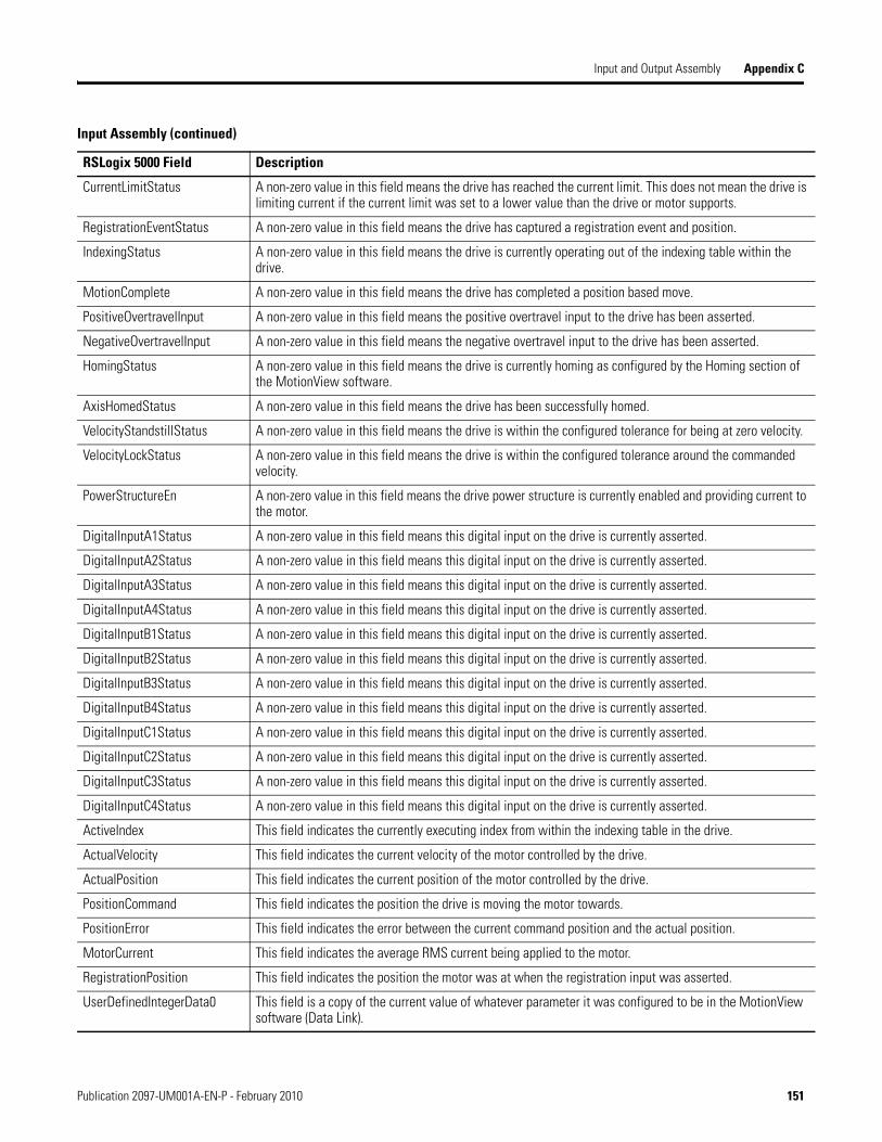
Input and Output Assembly Appendix C
CurrentLimitStatus A non-zero value in this field means the drive has reached the current limit. This does not mean the drive is limiting current if the current limit was set to a lower value than the drive or motor supports.
RegistrationEventStatus A non-zero value in this field means the drive has captured a registration event and position.
IndexingStatus A non-zero value in this field means the drive is currently operating out of the indexing table within the drive.
MotionComplete A non-zero value in this field means the drive has completed a position based move.
PositiveOvertravelInput A non-zero value in this field means the positive overtravel input to the drive has been asserted.
NegativeOvertravelInput A non-zero value in this field means the negative overtravel input to the drive has been asserted.
HomingStatus A non-zero value in this field means the drive is currently homing as configured by the Homing section of the MotionView software.
AxisHomedStatus A non-zero value in this field means the drive has been successfully homed.
VelocityStandstillStatus A non-zero value in this field means the drive is within the configured tolerance for being at zero velocity.
VelocityLockStatus A non-zero value in this field means the drive is within the configured tolerance around the commanded velocity.
PowerStructureEn A non-zero value in this field means the drive power structure is currently enabled and providing current to the motor.
DigitalInputA1Status A non-zero value in this field means this digital input on the drive is currently asserted.
DigitalInputA2Status A non-zero value in this field means this digital input on the drive is currently asserted.
DigitalInputA3Status A non-zero value in this field means this digital input on the drive is currently asserted.
DigitalInputA4Status A non-zero value in this field means this digital input on the drive is currently asserted.
DigitalInputB1Status A non-zero value in this field means this digital input on the drive is currently asserted.
DigitalInputB2Status A non-zero value in this field means this digital input on the drive is currently asserted.
DigitalInputB3Status A non-zero value in this field means this digital input on the drive is currently asserted.
DigitalInputB4Status A non-zero value in this field means this digital input on the drive is currently asserted.
DigitalInputC1Status A non-zero value in this field means this digital input on the drive is currently asserted.
DigitalInputC2Status A non-zero value in this field means this digital input on the drive is currently asserted.
DigitalInputC3Status A non-zero value in this field means this digital input on the drive is currently asserted.
DigitalInputC4Status A non-zero value in this field means this digital input on the drive is currently asserted.
ActiveIndex This field indicates the currently executing index from within the indexing table in the drive.
ActualVelocity This field indicates the current velocity of the motor controlled by the drive.
ActualPosition This field indicates the current position of the motor controlled by the drive.
PositionCommand This field indicates the position the drive is moving the motor towards.
PositionError This field indicates the error between the current command position and the actual position.
MotorCurrent This field indicates the average RMS current being applied to the motor.
RegistrationPosition This field indicates the position the motor was at when the registration input was asserted.
UserDefinedIntegerData0 This field is a copy of the current value of whatever parameter it was configured to be in the MotionView software (Data Link).
Input Assembly (continued)
RSLogix 5000 Field Description
Publication 2097-UM001A-EN-P - February 2010 151

Appendix C Input and Output Assembly
UserDefinedIntegerData1 This field is a copy of the current value of whatever parameter it was configured to be in the MotionView software (Data Link).
UserDefinedIntegerReal0 This field is a copy of the current value of whatever parameter it was configured to be in the MotionView software (Data Link).
UserDefinedIntegerReal1 This field is a copy of the current value of whatever parameter it was configured to be in the MotionView software (Data Link).
Input Assembly (continued)
RSLogix 5000 Field Description
Output Assembly
RSLogix 5000 Field Description
AbortIndex Upon transition from 0 to 1 of this field the drive aborts the current index or position based move the drive is executing and decel to zero velocity.
StartMotion Upon transition from 0 to 1 of this field the drive begins moving towards the position in the CommandPosition field below assuming the drive is enabled.
DefineHome Upon transition from 0 to 1 of this field the drive defines the current position of the motor to be home.
AbortHoming Upon transition from 0 to 1 of this field the drive aborts (decel to zero velocity) the homing operation.
StartHoming Upon transition from 0 to 1 of this field the drive begins homing as configured by the Homing section of the MotionView software assuming the drive is enabled.
DriveEn Upon transition from 0 to 1 of this field the drive enables, it turns on power structure, closes servo loops, tracks commands.
StartingIndex This field defines the first index the drive should execute if the drive is operating in Indexing mode.
ReferenceSource This field defines the type of control being exerted over EtherNet/IP network (0 = current, 1 = velocity, 2 = incremental position, 3 = absolute position, 4 = incremental registration, 5 = absolute registration).
AccelerationLimit This field defines the maximum acceleration the drive uses in accelerating towards the commanded position.
DecelerationLimit This field defines the maximum deceleration the drive uses in accelerating towards the commanded position.
CommandCurrentOrVelocity This field defines the commanded current (Amps RMS) or Velocity (User Units/s) if the ReferenceSource is 0 or 1 respectively and the drive is enabled.
VelocityLimit This field defines the maximum velocity the drive uses in the profile towards the commanded position.
CommandPosition This field defines the next position command the drive should move the motor towards, takes effect only upon 0 to 1 transition of StartMotion field above.
RegistrationOffset This field defines the offset from the registration event the drive should move to during an incremental or absolute registration based move.
UserDefinedIntegerData0 The value in this field is written to whatever parameter it was configured to be in the MotionView software (Data Link).
152 Publication 2097-UM001A-EN-P - February 2010

Input and Output Assembly Appendix C
UserDefinedIntegerData1 The value in this field is written to whatever parameter it was configured to be in the MotionView software (Data Link).
UserDefinedIntegerReal0 The value in this field is written to whatever parameter it was configured to be in the MotionView software (Data Link).
UserDefinedIntegerReal1 The value in this field is written to whatever parameter it was configured to be in the MotionView software (Data Link).
Output Assembly (continued)
RSLogix 5000 Field Description
Publication 2097-UM001A-EN-P - February 2010 153

Appendix C Input and Output Assembly
Notes:
154 Publication 2097-UM001A-EN-P - February 2010

Appendix D
Kinetix 300 Drive Safe Torque Off
Introduction This appendix introduces you to how the safe torque-off feature meets the requirements for safety category (CAT) 3 performance level d (PLd) applications.
Certification The safe torque-off circuit is type-approved and certified for use in safety applications up to and including safety category (CAT) 3, according to ISO 13849-1 Safety Category 3 Performance Level d.
Topic Page
Introduction 155
Certification 155
Understanding the Kinetix 300 Drive Safe Torque-off Feature 157
Description of Operation 158
Safe Torque Off Connector Data 159
Safe Torque Off Circuit Bypass Instructions 160
Wiring Your Kinetix 300 Drive Safe Torque Off Circuit 161
European Union Directives 161
Safe Torque Off Wiring Requirements 162
Kinetix 300 Drive Safe Torque Off Wiring Diagrams 163
Functional Proof Tests 164
Safe Torque Off Signal Specifications 165
Publication 2097-UM001A-EN-P - February 2010 155

Appendix D Kinetix 300 Drive Safe Torque Off
The TÜV Rheinland group has approved the Kinetix 300 drives for use in safety-related applications up to ISO 13849-1 Safety Category 3 Performance Level d, in which the de-energized state is considered to be the safe state. All of the examples related to I/O included in this manual are based on achieving de-energization as the safe state for typical machine safety systems.
IMPORTANT The system user is responsible for:
validation of any sensors or actuators connected to the drive system.
completing a machine-level risk assessment.
certification of the machine to the desired ISO 13849-1 Safety category.
project management and proof testing.
programming the application software and the device configurations in accordance with the information in this safety reference manual and the drive product manual.
156 Publication 2097-UM001A-EN-P - February 2010

Kinetix 300 Drive Safe Torque Off Appendix D
Safety Category 3 Requirements
Safety-related parts are designed such that:
a single fault in any of these parts does not lead to the loss of the safety function.
a single fault is detected whenever reasonably practicable.
accumulation of undetected faults can lead to the loss of the safety function.
Stop Category Definition
Stop category 0 is achieved with immediate removal of power to the actuator.
Understanding the Kinetix 300 Drive Safe Torque-off Feature
The safe torque-off circuit, when used with suitable safety components, provides protection according to ISO 13849-1 Safety Category 3. The safe torque-off option is just one safety control system. All components in the system must be chosen and applied correctly to achieve the desired level of operator safeguarding.
The safe torque-off circuit is designed to safely remove power from the gate firing circuits of the drive’s output power devices (IGBTs). This prevents them from switching in the pattern necessary to generate AC power to the motor.
You can use the safe torque-off circuit in combination with other safety devices to meet the stop and protection-against-restart requirements of ISO 13849-1.
IMPORTANT In the event of drive or control failure, the most likely stop category is category 0. When designing the machine application, timing and distance should be considered for a coast to stop. For more information regarding stop categories, refer to EN 60204-1.
ATTENTION This option is suitable for performing mechanical work on the drive system or affected area of a machine only. It does not provide electrical safety.
Publication 2097-UM001A-EN-P - February 2010 157

Appendix D Kinetix 300 Drive Safe Torque Off
Description of Operation The safe torque-off feature provides a method, with sufficiently low probability of failure on demand, to force the power-transistor control signals to a disabled state. When disabled, or any time power is removed from the safety enable inputs, all of the drive’s output-power transistors are released from the ON state, effectively removing motive power generated by the drive. This results in a condition where the motor is in a coasting condition (stop category 0). Disabling the power transistor output does not provide mechanical isolation of the electrical output, which may be required for some applications.
Under normal drive operation, the safe torque-off switches are energized. If either of the safety enable inputs are de-energized, the gate control circuit is disabled. To meet ISO 13849-1 safety category 3 both safety channels must be used and monitored.
SHOCK HAZARD To avoid an electric shock hazard, verify that the voltage on the bus capacitors has discharged before performing any work on the drive. Be sure the DC bus voltage across the B+ and B- terminals.
SHOCK HAZARD In Safe Torque-off mode, hazardous voltages may still be present at the motor. To avoid an electric shock hazard, disconnect power to the motor and verify that the voltage is zero before performing any work on the motor.
ATTENTIONPermanent magnet motors may, in the event of two simultaneous faults in the IGBT circuit, result in a rotation of up to 180 electrical degrees.
158 Publication 2097-UM001A-EN-P - February 2010

Kinetix 300 Drive Safe Torque Off Appendix D
Safe Torque Off Connector Data
This section provides safe torque-off (STO) connector and header information for the Kinetix 300 drive safe torque-off.
STO Connector Pinouts
Headers extend the STO connector signals for use in wiring or to defeat (not use) the safe torque-off function.
6-pin Safe Torque Off (STO) Connector
STO Pin Description Signal
1 +24V DC output from the drive +24V DC control
2 +24V DC output common Control COM
3 Safety status Safety Status
4 Safety input 1 (+24V DC to enable) Safety Input 1
5 Safety common Safety COM
6 Safety input 2 (+24V DC to enable) Safety Input 2
1 2 3 4 5 6STO
Safe Torque Off (STO) Connector
Kinetix 300 Drive, Bottom View(2097-V32PR4 is shown)
Publication 2097-UM001A-EN-P - February 2010 159

Appendix D Kinetix 300 Drive Safe Torque Off
Safe Torque Off Circuit Bypass Instructions
Use this section if your application does not require the use of the save torque-off function.
Follow these steps to bypass the safe torque-off circuit.
1. Prepare wires as listed.
2. Tin striped ends.
3. Wire STO terminal plug as shown.
(1) This voltage must under no circumstances be used to supply the safety circuits (terminals STO-3 …STO-6). This voltage is intended only for use in bypassing (disabling) the STO circuits should they not be required.
(2) A Separate +24V DC supply, rated to ISO 13849-1 category 3 must be supplied to STO-4…STO-6 to operate these inputs.
4. Torque all contacts to 0.2 N•m (1.8 lb•in).
5. Install STO terminal plug in STO connector.
ATTENTION The drive is supplied from the factory with the safe torque-off circuit enabled. The drive is not operational until +24V is present at terminals STO-4 and STO-6. For the proper safety connections, refer to the Single-axis Relay Configuration (Stop Category 0) diagram on page 163. Under certain applications when safety connections are not required the drive may be operated with the safety circuit disabled. The diagram below illustrates how to bypass the safety circuit.
Quantity ColorWire Sizemm2 (AWG)
Lengthmm (in.)
Strip Lengthmm (in.)
1 Black1.5 (16) 51 (2.0) 6 (0.25)
2 Red
Item Description
1 Black wire
2 Red wire
IMPORTANT Pins STO-1 (+24V DC Control) and STO-2 (Control COM) are used only by the motion-allowed jumpers to defeat the safe torque-off function. When the safe torque-off function is in operation, the 24V supply must come from an external source.
STO-1 (1)
STO-2 (1)
STO-3
STO-4 (2)
STO-5 (2)
STO-6 (2)
2
1
160 Publication 2097-UM001A-EN-P - February 2010

Kinetix 300 Drive Safe Torque Off Appendix D
Wiring Your Kinetix 300 Drive Safe Torque Off Circuit
This section provides guidelines for wiring your Kinetix 300 safe torque-off drive connections.
European Union Directives If this product is installed within the European Union or EEC regions and has the CE mark, the following regulations apply.
For more information on the concept of electrical noise reduction, refer to System Design for Control of Electrical Noise Reference Manual, publication GMC-RM001.
EMC Directive
This unit is tested to meet Council Directive 2004/108/EC Electromagnetic Compatibility (EMC) using the following standards, in whole or in part:
EN 61800-3 - Adjustable Speed Electrical Power Drive Systems, Part 3 - EMC Product Standard including specific test methods
EN 61000-6-4 EMC - Emission Standard, Part 2 - Industrial Environment
EN 61000-6-2 EMC - Immunity Standard, Part 2 - Industrial Environment
The product described in this manual is intended for use in an industrial environment.
CE Conformity
Conformity with the Low Voltage Directive and Electromagnetic Compatibility (EMC) Directive is demonstrated using harmonized European Norm (EN) standards published in the Official Journal of the European Communities. The safe torque-off circuit complies with the EN standards when installed according instructions found in this manual.
CE Declarations of Conformity are available online at:www.rockwellautomation.com/products/certification/ce.
Publication 2097-UM001A-EN-P - February 2010 161

Appendix D Kinetix 300 Drive Safe Torque Off
Low Voltage Directive
These units are tested to meet Council Directive 2006/95/EC Low Voltage Directive. The EN 60204-1 Safety of Machinery-Electrical Equipment of Machines, Part 1-Specification for General Requirements standard applies in whole or in part. Additionally, the standard EN 50178 Electronic Equipment for use in Power Installations apply in whole or in part.
Safe Torque Off Wiring Requirements
These are the safe torque-off (STO) wiring requirements. Wire should be copper with 75 C (167 F) minimum rating.
Safe Torque Off (STO) Terminal Plug
IMPORTANT The National Electrical Code and local electrical codes take precedence over the values and methods provided.
IMPORTANT Stranded wires must terminate with ferrules to prevent short circuits, per table D7 of EN 13849.
1 2 3 4 5 6
+24 V DC control
Control COM
Safety status
Safety input 1
Safety COM
Safety input 2
Safe Torque Off (STO) Terminal Plug Wiring
Safe Torque Off (STO) Connector Recommended Wire Size
Strip Lengthmm (in.)
Torque Value N•m (lb•in)Pin Signal
Stranded Wirewith Ferrulemm2 (AWG)
Solid Wiremm2 (AWG)
STO-1STO-2STO-3STO-4STO-5STO-6
+24V DC ControlControl COMSafety StatusSafety Input 1Safety COMSafety Input 2
0.75 (18) 1.5 (16) 6 (0.25) 0.2 (1.8)
162 Publication 2097-UM001A-EN-P - February 2010

Kinetix 300 Drive Safe Torque Off Appendix D
Kinetix 300 Drive Safe Torque Off Wiring Diagrams
This appendix provides typical wiring diagrams for the Kinetix 300 dive safe torque-off feature with other Allen-Bradley safety products.
For additional information regarding Allen-Bradley safety products, including safety relays, light curtain, and gate interlock applications, refer to the Safety Products Catalog, website www.ab.com/catalogs.
In the diagram below, the Kinetix 300 drive safe torque-off connector is shown wired to an Allen-Bradley safety relay.
Single-axis Relay Configuration (Stop Category 0)
IMPORTANT Pins STO-1 (+24V DC Control) and STO-2 (Control COM) are used only by the motion-allowed jumpers to defeat the safe torque-off function. When the safe torque-off function is in operation, the 24V supply must come from an external source.
IMPORTANT To be sure of system performance, run wires and cables in the wireways as established in the user manual for your drive.
+24V DCCOMStatusSafety Input 1Safety CommonSafety Input 2
NCNCNC
123456
S21 S22 S34 A2 14 24 34 42
A1 S11 S52 S12 13 23 33 41
Kinetix 300 Drive
Safe Torque Off (STO) Connector withWiring Header
External 24V COM
Safe Torque Off Demand
External +24V DC
Allen-BradleyMonitoring Safety
RelayMSR127RP
(440R-N23135)
Reset
Publication 2097-UM001A-EN-P - February 2010 163

Appendix D Kinetix 300 Drive Safe Torque Off
Functional Proof Tests ISO 13849-1 requires that functional proof tests be performed on the equipment used in the system. Proof tests are performed at user-defined intervals, not to exceed one year.
To proof test the safe torque-off function, you must interrupt power to the inputs of the safe torque-off function at pins STO-4 and STO-6 and verify that the drive is in the disabled state.
Proof Test Truth Table
Normal operation of the safe torque-off function, if monitored and verified, constitutes the proof test. A safe torque-off mismatch results in error code E67.
Troubleshooting the Safe Torque Off Function
IMPORTANT Users’ specific applications determine the time frame for the proof test interval, but it must not exceed one year due to the use of switches internal to the drive, as required by ISO 13849-1.
Safety Function State Safety Input 1(STO-4)
Safety Input 2(STO-6)
Safety Status Output (STO-3)
Drive Status Indication(1)
(1) Drive display changes to condition shown on enable of the drive (IN_ A3 Enable).
Normal operation Energized Energized Energized Run
Safe torque-off mismatchEnergized De-energized Energized E67
De-energized Energized Energized E67
Safe torque-off function engaged De-energized De-energized De-energized E67
Error Code
Fault Message RSLogix (HIM) Anomaly Potential Cause Possible Resolution
E67DriveHardFault(safe torque-off HW Flt)
Safe torque-off function mismatch. Drive will not allow motion.
Loose wiring at safe torque-off (STO) connector.
Cable/header not seated properly in safe torque-off (STO) connector.
Safe torque-off circuit missing +24V DC.
Verify wire terminations, cable/header connections, and +24V.
Reset error and run proof test.
If error persists, return the drive to Rockwell Automation.
ATTENTIONThe safe torque-off fault (E67) is detected upon demand of the safe torque-off function. After troubleshooting, a proof test must be performed to verify correct operation.
164 Publication 2097-UM001A-EN-P - February 2010

Kinetix 300 Drive Safe Torque Off Appendix D
Safe Torque Off Signal Specifications
The following tables provide specifications for the safe torque-off signals used in the Kinetix 300 drives.
Specifications for the ENABLE signals are described in this table.
Safe Torque Off Enable Signal Specifications
Attribute Value
Safety inputs
Insulated, compatible with single-ended output (+24V DC)
Enable voltage range: 20…24V DC
Disable voltage range: 0…1.0V DC
Input impedance 6.8 k
Safety status Isolated Open Collector (Emitter is grounded.)
Output load capability 100 mA
Digital outputs max voltage 30V DC
Publication 2097-UM001A-EN-P - February 2010 165

Appendix D Kinetix 300 Drive Safe Torque Off
Notes:
166 Publication 2097-UM001A-EN-P - February 2010

Appendix E
Configuring Indexing Parameters
Introduction Use this appendix when setting up the drive to run in Index mode.
About Kinetix 300 Drive Indexing
The software for the onboard indexing operation is accessed via a MotionView OnBoard program that is downloaded to any host computer that accesses the IP address of the drive. The indexing operation is also configurable over the EtherNet/IP connection using explicit message in RSLogix 5000 software.
When the Kinetix 300 drive is in Indexing mode the drive performs the required index based position move, for each index, according to the parameters shown in table on page 168. The Kinetix 300 drive supports up to 32 indexes.
The drive validates the index table before execution. During validation, if the drive encounters an error such as index entries that contain invalid values, the drive issues a fault and does not allow execution of the index table until the anomaly has been corrected.
In Indexing mode the Kinetix 300 drive begins executing indexes based on either a command received over the EtherNet/IP connection or immediately upon assertion of the hardware enable signal.
Topic Page
Introduction 167
About Kinetix 300 Drive Indexing 167
Indexing Parameters 168
Explicit Messages for Indexing 173
Publication 2097-UM001A-EN-P - February 2010 167

Appendix E Configuring Indexing Parameters
Indexing Parameters
Parameter Possible Values Units Description
Type AbsoluteIncrementalRegistration absoluteRegistration incrementalBlended
— Selects the indexing type and adjust the input parameters for that type.
Move Type S-curveTrapezoidal
— The acceleration and deceleration profile type.
Distance 1…268435.4560 User units How far to move
Register Distance 1…268435.4560 User units
Batch Count 1…2147483647 — How many times to execute index before moving on to next index
Dwell 0…65535 ms Time to remain at position before moving on to next index.
Velocity 0.0000…10,000,000.0000 User units/s
Speed when moving towards new position.
Acceleration 0.0000…10,000,000.0000 User units/s2
How quickly to accelerate towards configured velocity.
Deceleration 0.0000…10,000,000.0000 User units/s2
How quickly to decelerate towards zero velocity from configured velocity.
Next Index 0…31 — Next index to execute, if any.
Action Next indexWait for startNext index
What to do when current index is complete.
168 Publication 2097-UM001A-EN-P - February 2010

Configuring Indexing Parameters Appendix E
Registration Distance
If the indexing configuration Type is set to Registration Absolute or Registration Incremental an additional parameter of Registration Distance needs to be configured. In Registration Index mode, the drive moves the motor from its starting position the specified Distance provided that the registration sensor input is not detected. If the registration sensor input is detected, the move is adjusted so that the end position is determined by the Registration Distance setting. Registration Distance is the relative distance the motor travels beyond the position when a registration digital input is detected.
Registration Index Type
Blended
If the indexing configuration Type is set to Blended, the acceleration and deceleration parameters are not programmable, but calculated internally by the drive based upon distance and velocity between the two points of the move. The full profile is assembled by 'stitching' together a sequence of positions and velocities rather than complete move operations. The index table simply contains the position and velocities necessary to assemble the profile.
Example of Blended Indexing
Ve
loci
ty
Position
Registration
Registration Distance
Ve
loci
ty
Position
Index 1 Index 2 Index 3 Index 4
Publication 2097-UM001A-EN-P - February 2010 169

Appendix E Configuring Indexing Parameters
Action Parameter
The Action parameter can be set to be one of the following:
Stop
Wait for Start
Next Index
Stop
This action stops and holds zero velocity while remaining enabled. Upon assertion of the Start Index digital input or the Start Motion bit in the EtherNet/IP Output Assembly the Kinetix 300 drive begins executing the index in the Index system parameter.
Example of Stop and Hold Index Action
Wait for Start
This action waits for either the Start Motion bit to transition in the EtherNet/IP Output Assembly, or for the Start Index configured digital input to perform an active transition.
Example of Wait for Start Index Action
Ve
loci
ty
Position
Ve
loci
ty
Index 1 Index 2
Hold zero velocity until ‘Start Index’ command
170 Publication 2097-UM001A-EN-P - February 2010

Configuring Indexing Parameters Appendix E
Next Index
This action immediately moves to the next index as defined by the Next Index parameter.
Example of Next Index Action
Start Index
During powerup the Kinetix 300 drive is can do one of the following.
Automatically start the indexing program upon enabling of the drive.
Waiting for a digital input transition before starting the index.
Waiting for a software signal over EtherNet/IP network before starting the index.
When the drive is configured for AutoStart Index the drive begins executing the configured index immediately after the drive enables.
If the drive is not configured for AutoStart Indexing the drive does not begin executing the configured index until either the Start Motion bit transitions in the EtherNet/IP Output Assembly or the digital input configured for Start Index is transitioned to an active state.
The configuration for Start Index requires setting the following parameters either over EtherNet/IP Explicit Messaging or through the MotionView OnBoard software interface.
Ve
loc
ity
Index 1
Index 2
Dwell Time at zero velocity
Publication 2097-UM001A-EN-P - February 2010 171
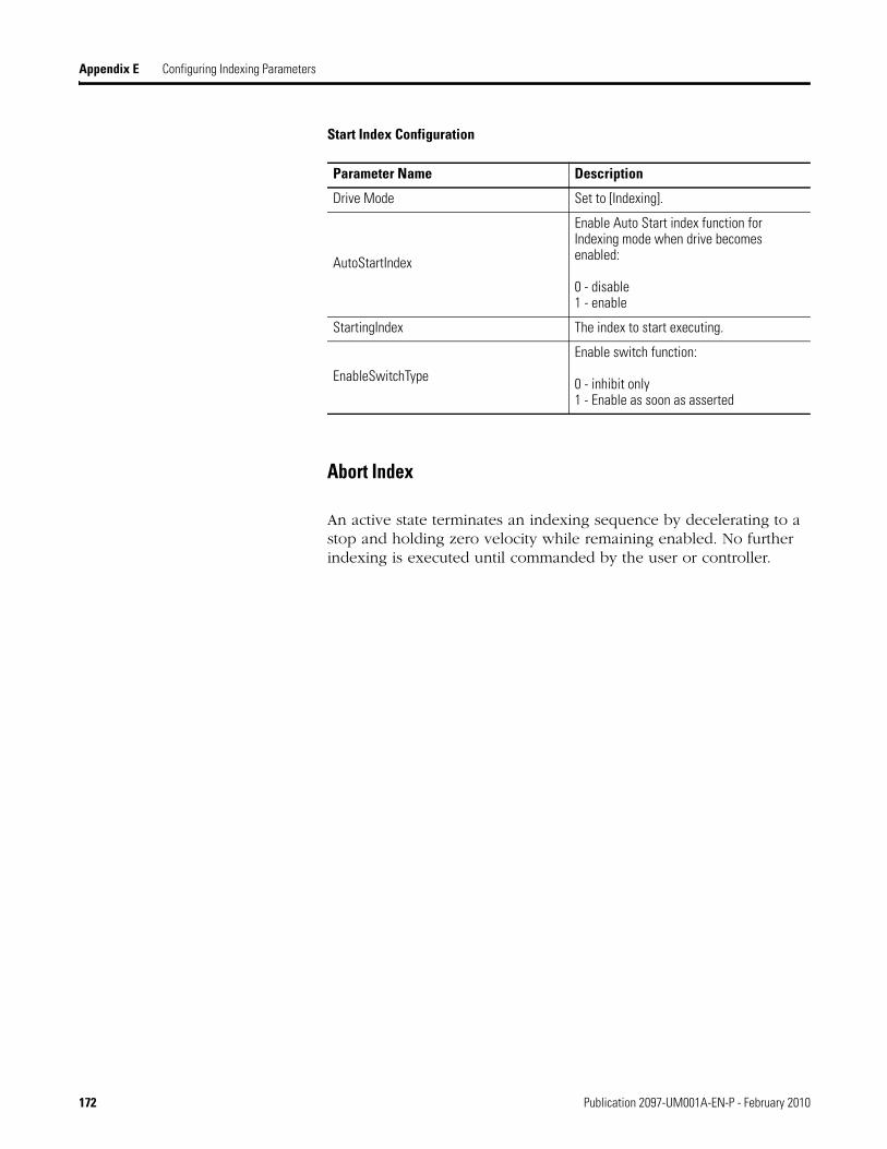
Appendix E Configuring Indexing Parameters
Start Index Configuration
Abort Index
An active state terminates an indexing sequence by decelerating to a stop and holding zero velocity while remaining enabled. No further indexing is executed until commanded by the user or controller.
Parameter Name Description
Drive Mode Set to [Indexing].
AutoStartIndex
Enable Auto Start index function for Indexing mode when drive becomes enabled:
0 - disable1 - enable
StartingIndex The index to start executing.
EnableSwitchType
Enable switch function:
0 - inhibit only1 - Enable as soon as asserted
172 Publication 2097-UM001A-EN-P - February 2010

Configuring Indexing Parameters Appendix E
Explicit Messages for Indexing
The Kinetix 300 drive provides an EtherNet/IP assembly for configuring all parameters associated with a a single index from within a single Explicit Message. To do this make a User-Defined type in the RSLogix 5000 program that follows the structure below. Send the User-Defined type in a Set Attribute Single Explicit Message to class 4, instance 115 and attribute 3.
Structure for Indexing User-Defined Type
RSLogix 5000 Field Description
Index Type This DINT contains the type of the index, absolute, incremental, registration or blended incremental.
Index Number This DINT contains the index number that is being modified.
Index Move Type This DINT contains the move type of the index S-Curve or Trapezoidal.
Index Distance This REAL contains the move distance of the index.
Index Batch Count This DINT contains the number of times the index should execute before moving to the next index.
Index Dwell This DINT contains the number of milliseconds the axis should remain at position before moving to the next index.
Index Velocity This REAL contains the velocity the axis should move at while moving the specified distance.
Index Maximum Acceleration
This REAL contains the maximum acceleration the axis should use in reaching the index velocity.
Index Maximum Deceleration
This REAL contains the maximum deceleration the axis should use in when approaching the target position.
Index Next Index This DINT contains the next index the drive should begin executing after completing this index.
Index Action This DINT contains the action the drive should take once this index is complete.
Index Registration Distance
This REAL contains the displacement from the registration position the axis should move to if a registration index is used.
Publication 2097-UM001A-EN-P - February 2010 173

Appendix E Configuring Indexing Parameters
Notes:
174 Publication 2097-UM001A-EN-P - February 2010

Appendix F
Kinetix 300 Drive Tag Numbers
Introduction This section lists the Kinetix 300 drive tag ID numbers and their description.
This section lists the Kinetix 300 drive tag ID numbers and their description.
To change these parameters using an Explicit Message configure the message to target class 374, the instance corresponds to the ID in the table below and the attribute is defined by the Kinetix 300 Drive Object attribute table on page 150.
IMPORTANT Memory module writes are limited to 1,000,000 per device. Ensure that all writes targeted at the memory module are necessary and not done as part of a background or cyclic task.
Kinetix 300 Drive Tag Numbers
ID Data Type Access Description
1 String R Drive’s identification string
2 String R/W Drive’s symbolic name
3 String R Drive’s serial number
7 REAL R Actual measured motor velocity
9 DINT R Drive Fault Register
10 String R Motor ID
11 String R Motor model
12 String R Motor vendor
14 DINT R Hallcode index
18 DINT R Motor moment of inertia, Jm
19 DINT R Motor voltage or back EMF constant, Ke
20 DINT R Motor torque or force constant, Kt
21 DINT R Motor phase-to-phase inductance, Lm
22 DINT R Motor phase-to-phase resistance, Rm
23 DINT R Motor’s max current(RMS)
Publication 2097-UM001A-EN-P - February 2010 175

Appendix F Kinetix 300 Drive Tag Numbers
24 DINT R Motor’s max velocity
25 DINT R Motor’s poles number
26 REAL R Encoder resolution
27 DINT R Nominal Motor’s terminal voltage
29 DINT R/W Enable switch function
30 REAL R/W Continuous RMS Current for motor selected.
32 REAL R/W Peak current limit for 8kHz operation (based upon motor selected)
35 REAL R/W Analog input current reference scale
36 REAL R/W Analog input velocity reference scale
39 DINT R/W Motor thermal protection function
44 DINT R/W Velocity loop Proportional gain
45 DINT R/W Velocity loop Integral gain
46 DINT R/W Position loop Proportional gain
47 DINT R/W Position loop Integral gain
48 DINT R/W Position loop Differential gain
49 DINT R/W Position loop integral gain limit
51 DINT R/W Gains scaling coefficient
53 DINT R/W Drive reset
54 DINT R Drive’s status register
57 DINT R/W Network group ID
58 REAL R/W Zero Speed window
59 REAL R/W At Speed window
60 REAL R/W Target Velocity for At Speed window
61 DINT R/W Position error
62 REAL R/W Position error time (time which position error has to remain to set-off position error fault)
65 DINT R Digital inputs states. A1 occupies Bit 0, A2-Bit 1…C4-Bit 11.
66 DINT R/W Digital outputs states.
67 DINT R/W Ethernet IP address. IP address changes at next boot up. 32 bit value
68 DINT R/W Ethernet IP NetMask. Mask changes at next boot up. 32 bit value
69 DINT R/W Ethernet Gateway IP address. Address changes at next boot up. 32 bit value
70 DINT R/W Use DHCP
71 REAL R Analog Input AIN1 current value
73 REAL R Measured Bus voltage
74 REAL R Heatsink temperature
Kinetix 300 Drive Tag Numbers (continued)
ID Data Type Access Description
176 Publication 2097-UM001A-EN-P - February 2010

Kinetix 300 Drive Tag Numbers Appendix F
75 DINT R/W Enable Accel/Decel function/limits for Velocity mode
76 REAL R/W Accel value for Velocity mode
77 REAL R/W Decel value for Velocity mode
78 DINT R/W Reset fault configuration
79 DINT R/W Master to system ratio (numerator)
80 DINT R/W Master to system ratio (denominator)
83 DINT R Extended status register
84 DINT R/W Hardware limit switches
85 DINT R/W Analog output function range: 0…8
86 REAL R/W Analog output scale for velocity quantities.
87 REAL R/W Analog output scale for current related quantities.
88 REAL W Analog output value.(Used if tag #85 is set to 0)
89 REAL R/W Analog input deadband. Applied when used as current or velocity reference.
90 REAL R/W Analog input offset. Applied when used as current/velocity reference
138 DINT W Turns on Profile Velocity for Internal Position Mode. Jogs motor in Position mode. Also set tags 176, and 177 for acceleration and deceleration and tag 180 for velocity
176 REAL R/W Accel value for position jog
177 REAL R/W Decel value for position jog
178 REAL R/W Decel value used for faults and aborts
179 DINT R/W Sets window for “In Position” Limits
180 REAL R/W Velocity reference for “Profiled” velocity
181 REAL R/W User units
182 DINT R/W A/B inputs reference counter value
183 REAL R Phase current
184 DINT R/W Target position in encoder pulses
185 DINT R/W Actual position in encoder pulses
186 DINT R Position error in encoder pulses
189 DINT R/W Input A1 de-bounce time in ms
190 DINT R/W Input A2 de-bounce time in ms
191 DINT R/W Input A3 de-bounce time in ms
192 DINT R/W Input A4 de-bounce time in ms
193 DINT R/W Input B1 de-bounce time in ms
194 DINT R/W Input B2 de-bounce time in ms
195 DINT R/W Input B3 de-bounce time in ms
196 DINT R/W Input B4 de-bounce time in ms
Kinetix 300 Drive Tag Numbers (continued)
ID Data Type Access Description
Publication 2097-UM001A-EN-P - February 2010 177

Appendix F Kinetix 300 Drive Tag Numbers
197 DINT R/W Input C1 de-bounce time in ms
198 DINT R/W Input C2 de-bounce time in ms
199 DINT R/W Input C3 de-bounce time in ms
200 DINT R/W Input C4 de-bounce time in ms
201 DINT R/W Programmable Output function
202 DINT R/W Programmable Output Function
203 DINT R/W Programmable Output Function
204 DINT R/W Programmable Output Function
205 DINT R Current hall code
206 DINT R Primary encoder current value
207 DINT R Registration position
208 REAL R Registration position
209 REAL R/W Target position
210 REAL R/W Actual position
211 REAL R Position error
216 DINT R/W Positive Software limit switch value in Encoder counts
217 DINT R/W Negative Software limit switch value in Encoder counts
218 DINT R/W Soft limit switch action code
219 REAL R/W Positive Software limit switch value in User Units
220 REAL R/W Negative Software limit switch value in User Units
227 REAL R/W Homing Mode: ACCEL rate
228 REAL R/W Homing Mode: Home Position Offset
229 DINT R/W Homing Mode: Home Position Offset in encoder counts
230 REAL R/W Homing Mode: Fast Velocity
231 REAL R/W Homing Mode: Slow Velocity
232 DINT R/W Homing Mode: Homing Method
234 DINT R/W Homing Mode: Home Switch Input Assignment to a physical input.
249 DINT R/W Datalink “A” for input assembly
250 DINT R/W Datalink “B” for input assembly
251 DINT R/W Datalink “C” for input assembly
252 DINT R/W Datalink “D” for input assembly
253 DINT R/W Datalink “A” for output assembly
254 DINT R/W Datalink “B” for output assembly
255 DINT R/W Datalink “C” for output assembly
256 DINT R/W Datalink “D” for output assembly
264 DINT R/W TCP reply delay value
Kinetix 300 Drive Tag Numbers (continued)
ID Data Type Access Description
178 Publication 2097-UM001A-EN-P - February 2010

Kinetix 300 Drive Tag Numbers Appendix F
266 DINT R/W Sets the mode of operation for the drive.
267 DINT R/W Enable Auto Start index function for Indexing mode when drive becomes enabled
268 DINT R/W Upon change from 0 to 1 the drive begins executing index
269 DINT W Value in this tag must change before time-out time is reached, otherwise the fault action is initiated.
270 DINT R/W Enable of the communication watchdog function
271 DINT R/W Time-out value in milliseconds between 10 and 1000
Indexing section
There are 11 tags per index. 32 Indexes total.
Index Base Address (B)
Index 0 272Index 1 283Index 2 294Index 3 305Index 4 316Index 5 327Index 6 338Index 7 349Index 8 360Index 9 371Index 10 382Index 11 393Index 12 404Index 13 415Index 14 426Index 15 437Index 16 448Index 17 459Index 18 470Index 19 481Index 20 492Index 21 503Index 22 514Index 23 525Index 24 536Index 25 547Index 26 558Index 27 569Index 28 580Index 29 591Index 30 602Index 31 622
B+0 DINT R/W Index move type of absolute, incremental, registration or blended incremental for index 0 - 31
B+1 DINT R/W S-Curve or Trapezoidal move for index 0 - 31
Kinetix 300 Drive Tag Numbers (continued)
ID Data Type Access Description
Publication 2097-UM001A-EN-P - February 2010 179

Appendix F Kinetix 300 Drive Tag Numbers
B+2 REAL R/W Maximum distance to move for index 0 - 31
B+3 REAL R/W Relative distance to move after registration event for registration types for index 0 - 31.
B+4 DINT R/W Number of types to repeat index before executing for index 0 - 31
B+5 DINT R/W Milliseconds to remain at current position before executing for index 0 - 31
B+6 REAL R/W Maximum velocity in UU while in motion for index 0 - 31
B+7 REAL R/W Maximum acceleration in UU while in motion for index 0 - 31
B+8 REAL R/W Maximum deceleration in UU while in motion for index 0 - 31
B+9 DINT R/W Next index to execute if action so indicates for index 0 - 31
B+10 DINT R/W Action to execute upon completing motion for index 0 - 31
624 DINT R/W Programmable input assignment
625 DINT R/W Programmable input assignment
626 DINT R/W Programmable input assignment
627 DINT R/W Programmable input assignment
628 DINT R/W Programmable input assignment
629 DINT R/W Programmable input assignment
630 DINT R/W Programmable input assignment
631 DINT R/W Programmable input assignment
632 DINT W Indexing starts from index specified
633 DINT R Aborts index in progress
634 DINT R Aborts homing in progress
637 DINT R Index currently executing
651 DINT R/W Motor Brake Release delay in ms
652 DINT R/W Motor Brake Engage delay in ms
653 DINT RO Fault E-code
654 DINT WO Reset ABS encoder error method
Kinetix 300 Drive Tag Numbers (continued)
ID Data Type Access Description
180 Publication 2097-UM001A-EN-P - February 2010

Appendix G
Using MicroLogix Explicit Messages with Kinetix 300 Drives
Introduction You can use the MicroLogix CIP Generic (MSG) instruction, also know as explicit message, capability of the MicroLogix 1100 Series B and MicroLogix 1400 controllers to read and write to the Kinetix 300 drive tags using EtherNet/IP. For a list of Kinetix 300 drive tags see Appendix F.
There are three data types for these tags: DINT, REAL and string. The MicroLogix drive uses long file elements such as L12:0 for DINTs, floating point file elements such as F13:0 for Real and string file elements such as ST14:0 for strings.
The attribute value is used to designate the data format DINT, REAL or string and memory location volatile or nonvolatile as shown in the following table.
Explicit messaging allows DINTs to be read into and written from long file elements directly and Real to be read into and written from floating point file elements directly. Strings must be read into integer file elements, such as N11:0, by the MSG instruction and then copied into a string file element. Similarly strings must be copied into integer file elements first before being written by the MSG instruction. Examples of each of these are shown in the pages that follow.
Attribute Value and Properties
Attribute Format Memory Stored In
0 DINT Volatile
1 DINT Nonvolatile
2 REAL Volatile
3 REAL Non-volatile
4 String Volatile
5 String Nonvolatile
IMPORTANT For each CIP Generic message (MSG) instruction, you must use both a unique message file element, for example MG9:0 and a unique extended routing information file element, for example RIX10:0. The routing information file element stores not only the path to the destination Kinetix 300 drive IP address, but also the specific Class/Instance/Attribute settings.
Publication 2097-UM001A-EN-P - February 2010 181

Appendix G Using MicroLogix Explicit Messages with Kinetix 300 Drives
Reading a DINT from volatile memory (example ID 73 – bus voltage)
Writing a DINT into non-volatile memory (example ID 232 – homing method)
182 Publication 2097-UM001A-EN-P - February 2010
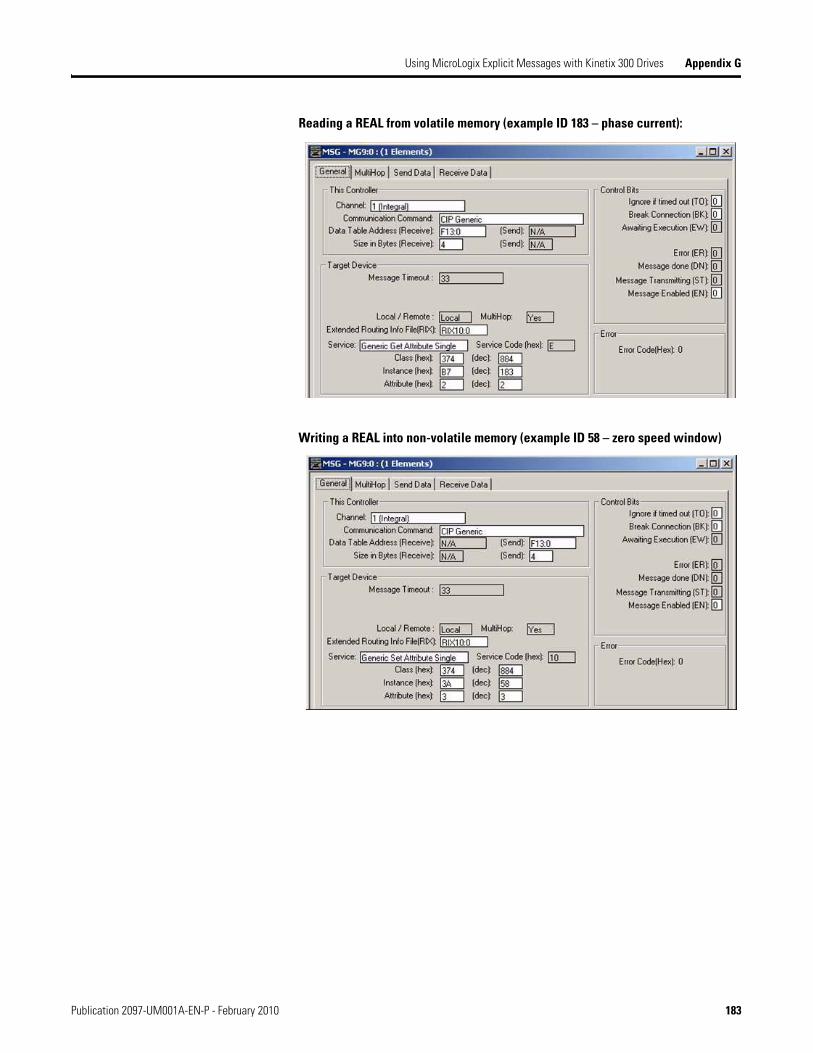
Using MicroLogix Explicit Messages with Kinetix 300 Drives Appendix G
Reading a REAL from volatile memory (example ID 183 – phase current):
Writing a REAL into non-volatile memory (example ID 58 – zero speed window)
Publication 2097-UM001A-EN-P - February 2010 183

Appendix G Using MicroLogix Explicit Messages with Kinetix 300 Drives
Reading a String from volatile memory (example ID 3 – drive’s serial number)
184 Publication 2097-UM001A-EN-P - February 2010

Using MicroLogix Explicit Messages with Kinetix 300 Drives Appendix G
Writing a String into non-volatile memory (example ID 2 – drive’s symbolic name)
Publication 2097-UM001A-EN-P - February 2010 185

Appendix G Using MicroLogix Explicit Messages with Kinetix 300 Drives
Notes:
186 Publication 2097-UM001A-EN-P - February 2010

Index
Numerics120V single-phase input power 1371756-Exx/x 971766-L32BXB 1461766-L32BXBA 1461769-L3xE 97240V single-phase input power 138
Aabout this publication 9AC line filters
specifications 132ac line filters
specifications 132additional resources 10analog current 105, 111, 113analog outputs 49analog reference 49analog velocity 105, 111, 112, 146applying power 101
Bback-up power 51bonding 23
EMI (ElectroMagnetic Interference) 22high frequency energy 24subpanels 24
brake currents 148building your own cables 54
Ccable
lengthCE 18
length, max 129cables
building your own cables 54Ethernet cable length 80maximum fdbk cable length 129shield clamp 74shield, EMC 70, 71
catalog, safety products 163category 3
requirements 157stop category definitions 157
CECE conformity 161complying with CE 161invalidating compliance 60
meeting requirements 162CE compliance 15, 60certification
specifications 130TÜV Rheinland 156user responsibilities 156
circuit breakerselection 19specifications 127
clamp 74clean zone 25clearance requirements 21configuring
Ethernet module 97connecting
external shunt resistor 79feedback 75I/O 75motor brake 73motor shield clamp 74
connector designators 33connector location 159contactor specifications 128controller properties 97conventions used in this manual 9coordinated system time master 98current mode 146
Ddate and time tab 98digital inputs 44digital outputs 48dirty zone 25download program 100drive
module properties 100wiring BP connector 66wiring IPD connector 67wiring MP connector 68wiring STO connector 66
drive propertiesdrive 100
Eelectric cylinder 144EMC
cable shield 70, 71directive 161motor ground termination 68motor ground termination at motor 68
Publication LDC-UM001A-EN-P - February 2010 187

Index
EMI (ElectroMagnetic Interference)bonding 22
enclosurerequirements 18sizing 20
environmental specifications 131error codes and messages 116Ethernet
address 100cables
RJ45 connectors 80connection 50module 97
properties 99
Ffeedback
cables and pinouts 75specifications 38
feedback power supply 43fuse 138
selection 19specifications 127
Ggeneric TTL incremental 38grounded power configuration 55grounding 61
multiple subpanels 62system to subpanel 61
HHF bonding 22high frequency energy 24
II/O
connections 75specifications 44, 48, 49
indexing 95, 105, 151, 167input power wiring
3-phase Delta 563-phase WYE 55determining input power 55grounded power configuration 55single-phase 57single-phase amplifiers on 3-phase power 58, 59
installing drive accessorieslow-profile connector kits 78
installing your drivebonding subpanels 24circuit breakers 19fuse selection 19HF bonding 22system mounting requirements 18transformer 19
inteconnect diagramthree-phase input power 139
interconnect diagram120V single-phase input power 137240V single-phase input power 138
interconnect diagrams2097 with MPL/MPF/MPS motor 141notes 136shunt resistor 140
ISO 13849-1 CAT 3requirements 157stop category definitions 157
Llinear stage 143low profile connector kits
wiring 78low voltage directive 162
Mmaintenance
troubleshooting 116master gearing 92, 105, 106, 111, 147
ratio 106maximum fdbk cable length 129
specifications 129mode
analog velocity 146current 146step and direction 146
module propertiesEthernet
module 99motors
brake wiring 73feedback pin-outs 76ground termination 68interconnect diagram
MPL/MPF/MPS 141power wiring
3-phase and brake 713-phase only 70TL-Series 69
shield clamp wiring 74
188 Publication 2097-UM001A-EN-P - February 2010

Index
testing 102thermal specifications 39tuning 102
mountingKinetix 300 drive 30torque
mountinghardware 30
MPL motor 142
Nnoise 25
Ooperation 158
understanding 157
Ppanel
requirements 18pin-outs
motor feedback connector 76power supply, feedback 43power up 101proof tests 164publications, related 10
Rrelated publications 10requirements
clearance 21RJ45
Ethernet connector 80routing power and signal wiring 54RSLogix 5000 software 97
Ssafe torque off feature
connector location 159safe torque-off
wiring 66safe-off feature
operation 158proof tests 164understanding operation 157wiring requirements 162
safety products catalog 163shield clamp 74
shunt resistor 28, 29interconnect diagram 140wiring 79wiring requirements 64
softwareRSLogix 5000 97
specification circut breaker 127specifications
AC line filters 132ac line filters 132analog outputs 49analog reference inputs 49certifications 130circuit breakers 127contactor ratings 128digital inputs 44digital outputs 48environmental 131Ethernet connection 50feedback
motor , general 38power supply 43
fuse 127maximum fdbk cable length 129motor feedback
generic TTL 41Stegmann 40Tamagawa 42
motor thermal 39transformer 128weight 130
Stegmann 38step and direction 105, 111, 146system mounting requirements 18system overview 12
TTamagawa 38training 9transformer sizing 19transformer specifications 128troubleshooting 116
error code E67 164error codes 116table 164
Vvelocity mode 146
Publication 2097-UM001A-EN-P - February 2010 189

Index
Wweight specifications 130who should use this manual 9wiring
building your own cables 54drive
BP connector 66IPD connector 67MP connector 68STO connector 66
electric cylinder 144grounded power configuration 55grounding 61I/O connections 75input power
determining type 55
linear stage 143low profile connectors 78maste gearing 147Micrologix 146motor brake 73motor cable shield clamp 74motor power 69, 70, 71MPL motor 142requirements 53
shunt resistor 64routing power and signal wiring 54safe torque-off feature 66shunt resistor 79
wiring guidelines 65wiring requirements 162
190 Publication 2097-UM001A-EN-P - February 2010


Publication 2097-UM001A-EN-P - February 2010 192Copyright © 2010 Rockwell Automation, Inc. All rights reserved. Printed in the U.S.A.
Rockwell Automation Support
Rockwell Automation provides technical information on the Web to assist you in using its products. At http://www.rockwellautomation.com/support/, you can find technical manuals, a knowledge base of FAQs, technical and application notes, sample code and links to software service packs, and a MySupport feature that you can customize to make the best use of these tools.
For an additional level of technical phone support for installation, configuration, and troubleshooting, we offer TechConnect support programs. For more information, contact your local distributor or Rockwell Automation representative, or visit http://www.rockwellautomation.com/support/.
Installation Assistance
If you experience an anomoly within the first 24 hours of installation, review the information that's contained in this manual.You can contact Customer Support for initial help in getting your product up and running.
New Product Satisfaction Return
Rockwell Automation tests all of its products to ensure that they are fully operational when shipped from the manufacturing facility. However, if your product is not functioning and needs to be returned, follow these procedures.
Documentation Feedback
Your comments will help us serve your documentation needs better. If you have any suggestions on how to improve this document, complete this form, publication RA-DU002, available at http://www.rockwellautomation.com/literature/.
United States or Canada 1.440.646.3434
Outside United States or Canada
Use the Worldwide Locator at http://www.rockwellautomation.com/support/americas/phone_en.html, or contact your local Rockwell Automation representative.
United States Contact your distributor. You must provide a Customer Support case number (call the phone number above to obtain one) to your distributor to complete the return process.
Outside United States Please contact your local Rockwell Automation representative for the return procedure.