KINEMATICS OF THE KNEE JOINT
7
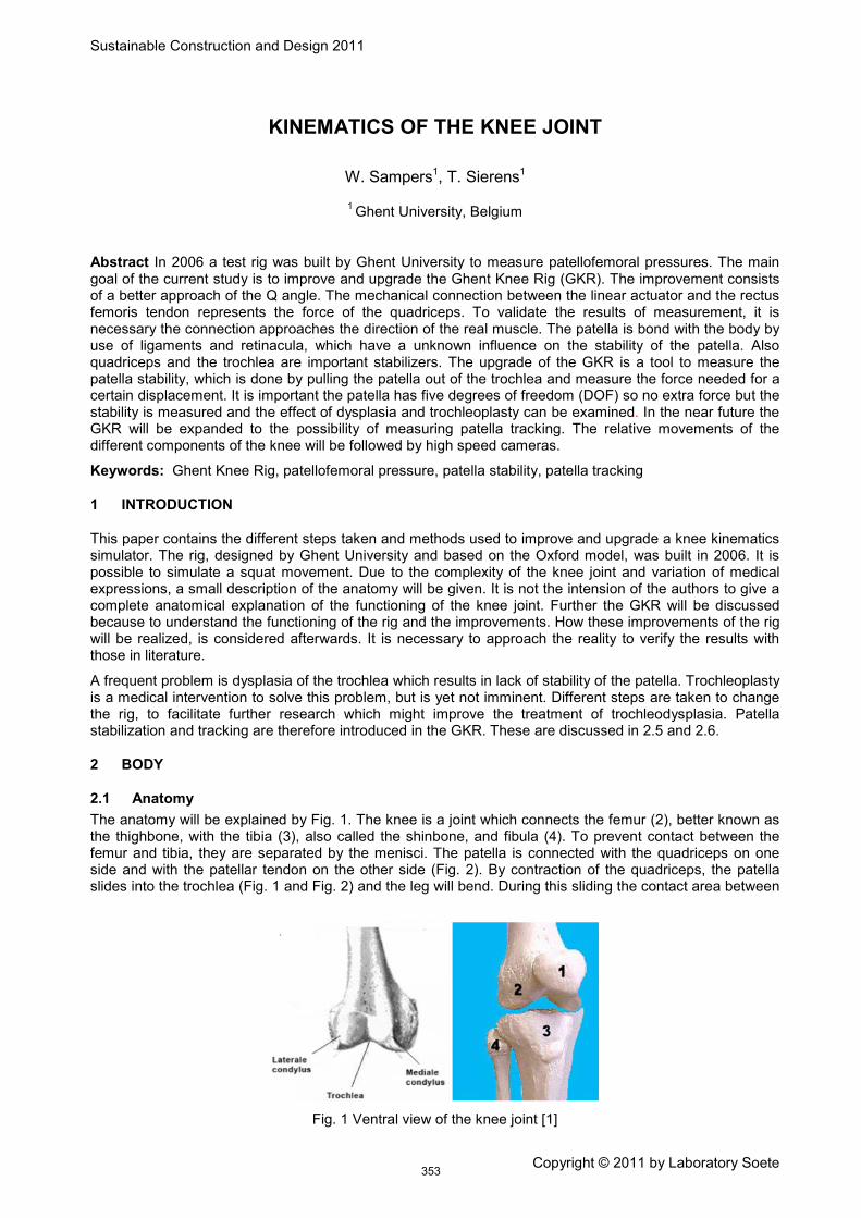
Sustainable Construction and Design 2011 Copyright © 2011 by Laboratory Soete KINEMATICS OF THE KNEE JOINT W. Sampers 1 , T. Sierens 1 1 Abstract In 2006 a test rig was built by Ghent University to measure patellofemoral pressures. The main goal of the current study is to improve and upgrade the Ghent Knee Rig (GKR). The improvement consists of a better approach of the Q angle. The mechanical connection between the linear actuator and the rectus femoris tendon represents the force of the quadriceps. To validate the results of measurement, it is necessary the connection approaches the direction of the real muscle. The patella is bond with the body by use of ligaments and retinacula, which have a unknown influence on the stability of the patella. Also quadriceps and the trochlea are important stabilizers. The upgrade of the GKR is a tool to measure the patella stability, which is done by pulling the patella out of the trochlea and measure the force needed for a certain displacement. It is important the patella has five degrees of freedom (DOF) so no extra force but the stability is measured and the effect of dysplasia and trochleoplasty can be examined. In the near future the GKR will be expanded to the possibility of measuring patella tracking. The relative movements of the different components of the knee will be followed by high speed cameras. Ghent University, Belgium Keywords: Ghent Knee Rig, patellofemoral pressure, patella stability, patella tracking 1 INTRODUCTION This paper contains the different steps taken and methods used to improve and upgrade a knee kinematics simulator. The rig, designed by Ghent University and based on the Oxford model, was built in 2006. It is possible to simulate a squat movement. Due to the complexity of the knee joint and variation of medical expressions, a small description of the anatomy will be given. It is not the intension of the authors to give a complete anatomical explanation of the functioning of the knee joint. Further the GKR will be discussed because to understand the functioning of the rig and the improvements. How these improvements of the rig will be realized, is considered afterwards. It is necessary to approach the reality to verify the results with those in literature. A frequent problem is dysplasia of the trochlea which results in lack of stability of the patella. Trochleoplasty is a medical intervention to solve this problem, but is yet not imminent. Different steps are taken to change the rig, to facilitate further research which might improve the treatment of trochleodysplasia. Patella stabilization and tracking are therefore introduced in the GKR. These are discussed in 2.5 and 2.6. 2 BODY 2.1 Anatomy The anatomy will be explained by Fig. 1. The knee is a joint which connects the femur (2), better known as the thighbone, with the tibia (3), also called the shinbone, and fibula (4). To prevent contact between the femur and tibia, they are separated by the menisci. The patella is connected with the quadriceps on one side and with the patellar tendon on the other side (Fig. 2). By contraction of the quadriceps, the patella slides into the trochlea (Fig. 1 and Fig. 2) and the leg will bend. During this sliding the contact area between Fig. 1 Ventral view of the knee joint [1] 353
Transcript of KINEMATICS OF THE KNEE JOINT
Sustainable Construction and Design 2011
Copyright © 2011 by Laboratory Soete
KINEMATICS OF THE KNEE JOINT
W. Sampers1, T. Sierens1
1
Abstract In 2006 a test rig was built by Ghent University to measure patellofemoral pressures. The main goal of the current study is to improve and upgrade the Ghent Knee Rig (GKR). The improvement consists of a better approach of the Q angle. The mechanical connection between the linear actuator and the rectus femoris tendon represents the force of the quadriceps. To validate the results of measurement, it is necessary the connection approaches the direction of the real muscle. The patella is bond with the body by use of ligaments and retinacula, which have a unknown influence on the stability of the patella. Also quadriceps and the trochlea are important stabilizers. The upgrade of the GKR is a tool to measure the patella stability, which is done by pulling the patella out of the trochlea and measure the force needed for a certain displacement. It is important the patella has five degrees of freedom (DOF) so no extra force but the stability is measured and the effect of dysplasia and trochleoplasty can be examined. In the near future the GKR will be expanded to the possibility of measuring patella tracking. The relative movements of the different components of the knee will be followed by high speed cameras.
Ghent University, Belgium
Keywords: Ghent Knee Rig, patellofemoral pressure, patella stability, patella tracking
1 INTRODUCTION
This paper contains the different steps taken and methods used to improve and upgrade a knee kinematics simulator. The rig, designed by Ghent University and based on the Oxford model, was built in 2006. It is possible to simulate a squat movement. Due to the complexity of the knee joint and variation of medical expressions, a small description of the anatomy will be given. It is not the intension of the authors to give a complete anatomical explanation of the functioning of the knee joint. Further the GKR will be discussed because to understand the functioning of the rig and the improvements. How these improvements of the rig will be realized, is considered afterwards. It is necessary to approach the reality to verify the results with those in literature.
A frequent problem is dysplasia of the trochlea which results in lack of stability of the patella. Trochleoplasty is a medical intervention to solve this problem, but is yet not imminent. Different steps are taken to change the rig, to facilitate further research which might improve the treatment of trochleodysplasia. Patella stabilization and tracking are therefore introduced in the GKR. These are discussed in 2.5 and 2.6.
2 BODY
2.1 Anatomy The anatomy will be explained by Fig. 1. The knee is a joint which connects the femur (2), better known as the thighbone, with the tibia (3), also called the shinbone, and fibula (4). To prevent contact between the femur and tibia, they are separated by the menisci. The patella is connected with the quadriceps on one side and with the patellar tendon on the other side (Fig. 2). By contraction of the quadriceps, the patella slides into the trochlea (Fig. 1 and Fig. 2) and the leg will bend. During this sliding the contact area between
Fig. 1 Ventral view of the knee joint [1]
353

Sustainable Construction and Design 2011
Copyright © 2011 by Laboratory Soete
these two will change and the patella will disappear deeper into the groove. Some knees have problems with the stability of the patella. Stabilizers of the patella are the trochlea and all ligaments, retinacula and muscles connected with the patella [1]. Every source of stabilization has a specific point of application and an own share of the force to do that. If the trochlea is not deep enough to ensure the stability of the patella, the problem is called dysplasia. It is logic that more force is needed to pull the patella out of a deeper groove, so a bigger stability is acquired. A medical operation to enlarge the trochlea, called trochleoplasty, is not yet imminent. Due to lack of information about this problem, it is very hard to recover this problem. Another problem that should be taken into account is that a small contact area between the trochlea and the patella leads to high pressure contacts and to unsatisfied patients. Due to the fact a knee has 6 DOF [3], a lot of parameters will change during this flexion-extension movement. The patellofemoral pressure and contact area, the force in the quadriceps, the stability of the patella, the relative movement of all the components, bones as well as the muscles all changes as a function of the flexion angle. To measure all these unknown parameters, it was indispensable to construct a test rig and so simulate the squat.
Fig. 2 medial view of the a) extension b) flexion position [2]
2.2 Existing test rig Since the building of the GKR in 2006 (Fig. 3), it was possible to measure the patellofemoral pressures by the use of a sensor while the knee is making a flexion-extension motion. This is a simplified movement which people use daily e.g. walking, go up-and downstairs, cycling, etc.
The fresh frozen legs are defrost and disconcerted from the skin. To connect the specimen with the GKR, tibia and femur are cemented in two cylinders. These cylinders can easily be mounted in the rig with bolts (Fig. 3). The ankle and hip joint are substituted by two mechanical joints (D and H) which take care of the desired position of the knee. The hip has 3 DOF: one vertical translation and two rotations (flexion-extension movement and internal-external rotation). The ankle has 5 DOF: two translations in the horizontal plane and 3 rotation movements. It is mathematical proven that this testing station allows 6 freedoms [4]. The horizontal translations of the ankle however are never used, but if necessary for tests, they are available. The quadriceps femoris tendon is connected to a linear actuator (C) by way of a clamp system (E) and a steel cable (F). This cable, which is the replacement of the quadriceps, is guided through a pulley (G). When the actuator comes into operation, the steel cable pulls the tendon and the flexion-extension movement of the knee will start. The actuator and hip joint are mounted in such a way they move up and down with the knee, which is loaded through this by approximate 30kg. So they are subjected to inertia forces, which implies extra vibrations and less accurate measurements. However, this has to be nuanced, the speed of the actuator is only 2,75mm/s what will result in negligible inertia forces. A loadcell, connected to the end of the motor, measures the force to stretch the leg. The mechanical hip joint, the actuator and the horizontal profile (B) will move up and down and take care of the weight, carried by the leg. The patellofemoral pressures are measure by the use of a sensor (I), which is mounted between the femur and patella in a gap of approximate 5cm on the lateral side of the knee.
a) b)
354

Sustainable Construction and Design 2011
Copyright © 2011 by Laboratory Soete
Fig. 3 a) front-view b) side-view of the specimen in the GKR [5]
2.3 Problems and solutions The main problem of the original rig is the direction of the force, acting on the patella. As already mentioned, the quadriceps is replaced by a steel cable. To have accurate results of the test, it is necessary to approach the direction of the real muscle. The pulley (G), which is leading the cable, is placed next to the hip joint (D) (Fig. 3). This is not in agreement with reality due a wrong the Q angle (a measure for the angle between quadriceps, which is more lateral situated, and the patella ligament [1]). The use of a steel cable and related tailpieces is not user-friendly and inaccurate due to strain.
To make the Q angle more realistic, some alterations on the test rig are necessary. The actuator (green) is moved to the other side of the frame (Fig. 4) so motor and specimen (orange) are oriented to the same side of the rig. Due to the incapacity of the motor to take forces other than linear, the pulley (blue) is moved in such a way the acting force of the cable is lying perfect in line with the actuator. Because the vector of the quadriceps force is oriented towards the hip, the best position of the pulley is as close as possible to the mechanical rotation point. Due to the fact all specimen are different and left as well as right knees are tested, it is necessary the pulley is adjustable stationed. This is solved by milling grooves in the pulley system for mounting it with 4 prestressed bolts in the horizontal profile, so the wanted height can be established. Before testing, an optimal position of the pulley is chosen, during the test remains the position unchanged.
The cable problem is solved by replacing the wire by a chain which has a higher stiffness and can easily be connected to the motor on one side and the clamp system on the other side. A chain however is difficult and time-consuming to vary in length. To meet this deficiency, the actuator is no longer mounted fixed with regard to the horizontal profile to which it was initial fastened (Fig. 4). The motor is placed on a rail system which is connected with the hip joint and thus is moving up and down. The same principles count as for the pulley are valid. The linear actuator is mounted to a rail plate with 4 prestressed bolts. The relative position of the motor with regard to the rail plate is chosen so that the chain is not hanging loose, in other words, the motor is placed in the highest position the chain allows.
.
a) b)
355

Sustainable Construction and Design 2011
Copyright © 2011 by Laboratory Soete
Fig. 4 Drawing changes in GKR
2.4 Protocol of the patellofemoral pressure To ensure the accuracy of the test results, it is necessary to write an unambiguous protocol so results of different specimen can be compared with each other and with literature. Specimen are numbered and all available information (age, time post mortum, temperature, transport method, etc.) is carefully hold out. An incision is made on the lateral side of the knee, to place a pressure sensor between patella and femur. The Tekscan sensor is able to measure pressures up to 13 MPa and is designed to measure contact surfaces and pressure distributions in joints [6]. It is the industry standard for applications where real-time dynamic joint simulations are required. The system exists of a sensor, an interface and an extensive software packet for the processing of the data. The sensor is 0,1mm thick and is built up by pressure sensitive pixels which are brought into matrix formation1
The positioning of the specimen in the GKR happens as described in 2.2.
. Due to the small thickness, a small layer of Teflon is added to strengthen the film so it can easily be placed. The Teflon also helps to prevent the rise of creases.
2.5 Patella stabilisation As discussed in 2.1 the stability of the patella is dependent of the trochlea, all ligaments, retinacula and muscles connected with the patella. To examine the influence of these stabilizers a new tool has to be built on the GKR. This is done by pulling the patella in the lateral and medial direction. During this procedure, the force needed to displace the patella 1cm is measured. The experiment is repeated for different flexion angles to compare. The system introduced in the GKR is based on methods used in the rig from the Departments of Mechanical Engineering and of Musculoskeletal Surgery from the Imperial College in London [7].
According to experiments in literature, the specimen is placed in horizontal plane, with the lateral side oriented upwards (Fig. 5). The knee is positioned in the desired flexion angle and femur is completely fixed to the test rig and has no degrees of freedom left. But for the flexion-extension movement, the tibia has all degrees of freedom. The quadriceps are connected with weights which have a total weight of 30N or 175N [8]. The force acting on the quadriceps is divided in different parts, to approach reality (Fig. 5). Every muscle is surrounded by linen which in turn are connected to the weights. The different parts of the quadriceps, with each its own direction and weight is summarized in Table 1. The patella is connected with a mounting device which has 3 DOF: anterior-posterior, proximal-distal and flexion-extension rotation. The crosshead itself is connected with Instron 1122 Materials. This is comparable with a tensile testing machine with a capacity of 5kN [9]. The tensile testing machine is provided with a load cell. The connection between patella and mounting device is a ball-and-socket joint which has a diameter of 10mm and is cemented into
1 The pixel is an electrical resistance, its value being dependent on pressure.
356

Sustainable Construction and Design 2011
Copyright © 2011 by Laboratory Soete
Fig. 5 Test rig patella stabilisation [10]
the patella, 10 mm deep with regard to the anterior surface (Fig. ). The ball-and-socket joint are necessary to allow the natural rotations of the patella. The connection between the tensile testing machine and the patella has 5 DOF; only the medial-lateral movement is prohibited. While this movement is enforced by the tensile testing machine by a chosen flexion angle, the required force is each millimeter measured. The speed of the displacement is 100mm/min [7].
However the patella stability tool in the GKR is based on the one discussed above, the design is certainly not the same. Because there is no space enough to place it and due to the little movement and forces needed, the tensile testing machine will be replaced by a linear actuator. The 5 DOF from the ankle will, due to the current rig, be reduced to two (ab –and adduction; internal-external rotation). The 5 DOF of the connection between the patella and the mounting device will be kept. More information cannot be given because this project is only in the initial stage.
Lateral Medial Anterior Posterior Load Load 1 Load 2
quadriceps
30N/175N
VL longus 14° 0° 33 % 9,9 N 57,75 N
VL obliquus 35° 33° 9 % 2,7 N 15,75 N
VM longus 15° 0° 14 % 4,2 N 24,5 N
VM obliquus 47° 44° 9 % 2,7 N 15,75 N
RF+VI 0° 0° 35 % 10,5 N 61,25 N
Tractus
5N/30N ITB 0° 6° 5 N 1 N
Table 1 Directions and forces on quadriceps 2
2 VL = Vastus Lateralis, VM = Vastus Medialis, RF = Rectus Femoris, VI = Vastus Intermedius, ITB = iliotibial band
[10]
357

Sustainable Construction and Design 2011
Copyright © 2011 by Laboratory Soete
Fig. 6 Ball-and-socket joint in patella [11]
2.6 Patella tracking For completion patella tracking is mentioned however less information can be given. This is a measurement of the relative movement of all components of the knee. While the specimen is making a walking motion (or a squat), the kinematics of all parts can be registered by the use of a camera system in function of the flexion angle.
3 CONCLUSIONS
The main goal of this study is to improve and to update the GKR. The results should be more accurate due to the better approach of reality by improve of the Q angle and the possibility to place the pulley closer to the hip joint. Because the use of a steel cable is replaced by a chain, the test rig should be more user-friendly. However we cannot confirm these assumptions because the completion of the construction is not ready. Plans to operate and measure the patellofemoral pressure should be possible from March 2011.
The concept and rough sketches for the patella stability tool is in the making. We expect at the latest to test early April 2011. Completing the patella tracking is the next step in this research.
4 NOMENCLATURE
P Pressure Pa
t Time s
m Mass kg
v Velocity m/s
s Distance m
F Force N
DOF Degrees of freedom
GKR Ghent Knee Rig
5 ACKNOWLEDGEMENTS
First of all we want to thank P. De Baets for his help in general. As the promotor for the project, he helped us with the planning, progress and technical support. Secondly we want to mention W. Ost for the advice
358

Sustainable Construction and Design 2011
Copyright © 2011 by Laboratory Soete
he gave us and helping to order all parts. We must not forget A. Van Haver, who is copromotor for this project. She was helpful for the medical part of this study.
6 REFERENCES
[1] Stevens and Dockers. Onderzoek naar de krachtwerking van het patellofemoraal gewricht en ontwerp en constructie van een experimenteel belastingsmodel, 2006.
[2] F.H. Netter, Atlas of human anatomy, RR Donnelley, 2007
[3] J.A. Fisk, evaluating the accuracy of knee kinematics measured in six degree freedom using surface markers, 2004
[4] A.B. Zavatsky. The importance of quadriceps and hamstring muscle loading on knee kinematics and in-situ forces in the ACL. Journal of Biomechanics, 32:395 – 400, 1999.
[5] A. Van Haver, J. Quintelier, P. Verdonck, F. Almqvist, M. De Beule and P. De Baets, Patellofemoral contact during squat simulation on cadaveric knees, Day of research 2010, 2010
[6] K-scan website: http://www.tekscan.com/medical/system_kscan.htms, 2006
[7] W. senavongse, F. Farahmand, J. Jones, H. Andersen, A.M.J. Bull, A.A. Amis, Quantitative measurement of patellofemoral joint stability: force-displacement behavior of the human patella in vitro, Journal of orthopaedic Research 21, 780-786, 2003
[8] W. senavongse, C. Oguz, A.M.J. Bull, A.A. Amis, D. Dejour, The effect of trochleoplasty on patellar stability and kinematics, the journal of bone and joint surgery, 2008
[9] Instron website: http://www.instron.com/wa/product/used-equipment.aspx, 2010
[10] A.M. Merican, E. Kondo, A.A. Amis, The effect on patellofemoral joint stability of selective cutting of lateral retinacular and capsular structures, Journal of biomechanics, 291-296, 2009
[11] J. Christoforakis, A.M.J. Bull, R.K. Strachan, R. Shymkiw, W. Senavongse, A.A. Amis, Effects of lateral retinacular release on the lateral stability of the patella, 2006
359