KINEMATICS OF AN OVERCONSTRAINED … · link spatial mechanism which does not satisfy the Kutzbach...
15
International Journal of Advanced Research in ISSN: 2278-6252 Engineering and Applied Sciences Impact Factor: 5.795 Vol. 4 | No. 12 | December 2015 www.garph.co.uk IJAREAS | 9 KINEMATICS OF AN OVERCONSTRAINED MECHANISM IN PRACTICE Vandan Kamlakar Gundale* Abstract: In 1939 Paul Schatz, a Swiss anthroposophist and geometrician had invented a mechanism which with few links generates spatial motions. Mixing machine based on this Schatz mechanism uses a highly ordered form of three dimensional motion that brings centrifugal and centripetal forces to dynamic balance. This results in ideal mixing environment. While exploring this mechanism, it was then clear that this mechanism is a six link spatial mechanism which does not satisfy the Kutzbach criterion of full cycle mobility. Such practical application of overconstrained mechanism has very interesting characteristics. Without the use of cams or gears it performs spatial motion. The work described in this paper is an attempt to describe general kinematics of this six link mechanism involving only revolutes, using matrix method. As discussed here, a spatial mechanism containing only revolutes is derived from the seven link kinematics chain. However mechanism described here has only six links including the fixed base. If the link lengths are selected arbitrary, then the mechanism will result in immobility with no degrees of freedom. Mobility of the mechanism is because of specific linear dimensions only. The mobility of the mechanism is proved with this kinematics description. Keywords: overconstrained mechanism, 3-D Mixer, D & H Matrix, kinematics, mobility criterion, spatial mechanism *Workshop Superintendent, Workshop, B. & B. Institute of Technology, Vallabh Vidyanagar, Anand, Gujarat, India
Transcript of KINEMATICS OF AN OVERCONSTRAINED … · link spatial mechanism which does not satisfy the Kutzbach...
International Journal of Advanced Research in ISSN: 2278-6252
Engineering and Applied Sciences Impact Factor: 5.795
Vol. 4 | No. 12 | December 2015 www.garph.co.uk IJAREAS | 9
KINEMATICS OF AN OVERCONSTRAINED MECHANISM IN PRACTICE
Vandan Kamlakar Gundale*
Abstract: In 1939 Paul Schatz, a Swiss anthroposophist and geometrician had invented a
mechanism which with few links generates spatial motions. Mixing machine based on this
Schatz mechanism uses a highly ordered form of three dimensional motion that brings
centrifugal and centripetal forces to dynamic balance. This results in ideal mixing
environment. While exploring this mechanism, it was then clear that this mechanism is a six
link spatial mechanism which does not satisfy the Kutzbach criterion of full cycle mobility.
Such practical application of overconstrained mechanism has very interesting
characteristics. Without the use of cams or gears it performs spatial motion. The work
described in this paper is an attempt to describe general kinematics of this six link
mechanism involving only revolutes, using matrix method. As discussed here, a spatial
mechanism containing only revolutes is derived from the seven link kinematics chain.
However mechanism described here has only six links including the fixed base. If the link
lengths are selected arbitrary, then the mechanism will result in immobility with no degrees
of freedom. Mobility of the mechanism is because of specific linear dimensions only. The
mobility of the mechanism is proved with this kinematics description.
Keywords: overconstrained mechanism, 3-D Mixer, D & H Matrix, kinematics, mobility
criterion, spatial mechanism
*Workshop Superintendent, Workshop, B. & B. Institute of Technology, Vallabh Vidyanagar,
Anand, Gujarat, India
International Journal of Advanced Research in ISSN: 2278-6252
Engineering and Applied Sciences Impact Factor: 5.795
Vol. 4 | No. 12 | December 2015 www.garph.co.uk IJAREAS | 10
OVERCONSTRAINED MECHANISM:
A mechanism is commonly identified as a set of moving or working parts in a machine or
other device essentially as a means of transmitting, controlling, or constraining relative
movement. A mechanism is often assembled from gears, cams and linkages, though it may
contain other specialized components, such as springs, ratchets, brakes, and clutches, as
well.
Reuleaux published the first book on theoretical kinematics of mechanisms in 1875 (Hunt,
1978). Later on the general mobility criterion of an assembly was established by Grübler in
1921 and Kutzbach in 1929, respectively (Phillips, 1984), based on the topology of the
assembly [1]. However, it was found that this criterion is not a necessary condition. Some
specific geometric condition in an assembly could make it a mechanism even though it does
not obey the mobility criterion. This type of mechanisms is called an over-constrained
mechanism.
The first published research on over-constrained mechanisms can be traced back to 150
years ago when Sarrus discovered a six-bar mechanism capable of rectilinear motion [1].
Gradually more over-constrained mechanisms were discovered by other researchers in the
next half a century. However, most over-constrained mechanisms have rarely been used in
industrial applications because of the development of gears, cams and other means of
transmission, except two of them: the double- Hooke’s-joint linkage, which is widely applied
as a transmission coupling, and the Schatz linkage, which is used as a 3-Dimensional Mixing
machine for mixing fluids and powders. Over the recent half century, very few Over-
constrained mechanisms have been found. Most research work on Over-constrained
mechanisms is mainly focused on their kinematic characteristics.
LINKAGES AND OVER-CONSTRAINED LINKAGES [1]
A linkage is a particular type of mechanism consisting of a number of interconnected
components, individually called links. The physical connection between two links is called a
joint. All joints of linkages are lower pairs, i.e. surface-contact pairs, which include spherical
joints, planar joints, cylindrical joints, revolute joints, prismatic joints, and screw joints. Here
we limit our attention to linkages whose links form a single loop and are connected only by
revolute joints, also called rotary hinges. These joints allow one-degree-of-freedom
movement between the two links that they connect. The kinematic variable for a revolute
joint is the angle measured around the two links that it connects.
International Journal of Advanced Research in ISSN: 2278-6252
Engineering and Applied Sciences Impact Factor: 5.795
Vol. 4 | No. 12 | December 2015 www.garph.co.uk IJAREAS | 11
From classical mobility analysis of mechanisms, it is known that the mobility m of a linkage
composed of n links that are connected with p joints can be determined by the Kutzbach (or
Grübler) mobility criterion (Hunt, 1978):
m = 6(n - p -1) + f …………………………………………... (1)
where Σ f is the sum of kinematic variables in the mechanism.
For an n--link closed loop linkage with revolute joints, p = n, and the kinematic variable Σ f =
n. Then the mobility criterion in (1) becomes;
m = n - 6 …………………………….…………………... (2)
So in general, to obtain a mobility of one, a linkage with revolute joints needs at least seven
links. It is important to note that (2) is not a necessary condition because it considers only
the topology of the assembly. There are linkages with full-range mobility even though they
do not meet the mobility criterion. These linkages are called over-constrained linkages.
Their mobility is due to the existence of special geometry conditions among the links and
joint axes that are called over-constrained conditions.
Denavit and Hartenberg (1966) set forth a standard approach to the analysis of linkages,
where the geometric conditions are taken into account. They pointed out that, for a closed
loop in a linkage, the necessary and sufficient mobility condition is that the product of the
transform matrices equals the unit matrix, i.e.
n1 34 23 12[T ] [T ][T ][T ] = I ……………………………. (3)
Where [T i(i+1)] is the transfer matrix between the system of link (i −1)i and the system of link
i(i +1).
Over-constrained mechanisms have many appealing characteristics. Most of them are
spatial mechanisms. Their spatial kinematic characteristics make them good candidates in
modern linkage designs where spatial motion is needed. Another advantage of Over-
constrained mechanisms is that they are mobile using fewer links and joints than it is
expected. For example, in normal closed loop revolute joint spatial mechanisms, the linkage
should have at least seven links to be mobile. Over-constrained mechanisms can be mobile
with four, five or six links. Fewer links and joints in a mechanism mean reduction in cost and
complexity [2].
While many over-constrained mechanisms have been discovered, only a few of them have
been used in practical applications. There are many reasons for this. Most of the engineers
International Journal of Advanced Research in ISSN: 2278-6252
Engineering and Applied Sciences Impact Factor: 5.795
Vol. 4 | No. 12 | December 2015 www.garph.co.uk IJAREAS | 12
are unaware of the existence of spatial over-constrained mechanisms and their properties.
For example, very few engineers in industry know the four-bar Bennett or the six-bar
Bricard spatial mechanisms and their properties and hence they can not consider these
mechanisms in their designs. The other reason for not using over-constrained mechanisms
in industrial applications is that most of the known over-constrained mechanisms have
complex kinematic properties. This is because these mechanisms have been found using
mobility criteria only and not other criteria as well, such as to satisfy a desired input-output
relationship.
The minimum number of links to construct a mobile loop with revolute joints is four as a
loop with three links and three revolute joints is either a rigid structure or an infinitesimal
mechanism when all three revolute axes are coplanar and intersect at a single point
(Phillips, 1990). So, 3D over-constrained linkages can have four, five or six links. When these
linkages consist of only revolute joints, they are called 4R, 5R or 6R linkages.
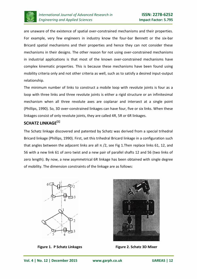
SCHATZ LINKAGE[1]
The Schatz linkage discovered and patented by Schatz was derived from a special trihedral
Bricard linkage (Phillips, 1990). First, set this trihedral Bricard linkage in a configuration such
that angles between the adjacent links are all π /2, see Fig 1.Then replace links 61, 12, and
56 with a new link 61 of zero twist and a new pair of parallel shafts 12 and 56 (two links of
zero length). By now, a new asymmetrical 6R linkage has been obtained with single degree
of mobility. The dimension constraints of the linkage are as follows:
Figure 1. P Schatz Linkages Figure 2. Schatz 3D Mixer
International Journal of Advanced Research in ISSN: 2278-6252
Engineering and Applied Sciences Impact Factor: 5.795
Vol. 4 | No. 12 | December 2015 www.garph.co.uk IJAREAS | 13
12 56 23 34 45 61a = a =0, a = a = a =a, a = 3a ……………………………………… (4)
12 23 34 45 56 = = = = = 2 ……………………………………… (5)
……………………………………. (6)
Brát (1969) studied the kinematic description of the Schatz linkage using the matrix method.
This linkage is also known by the name Turbula because it constitutes the essential
mechanism of a machine by that name, see Fig. 2. It is used for mixing fluids and powders.
Spatial mechanisms have little applications, because the complexities of kinematic relations
have prevented solutions by conventional methods. The graphical method has major
limitations in their applications to spatial problems as they depend on the choices which
require a visualization of the motion & visualization of spatial mechanism is very difficult.
A method based on the matrix algebra, initiated by J. Denavit & R. S. Hartenberg is proved
very useful till today. The procedure defines all parameters required for a kinematic analysis
and allows formulating spatial problems in terms of matrix equations
DESCRIPTION OF D & H MATRIX ALGEBRA METHOD FOR ANALYSIS OF
SPATIAL MECHANISMS [3]
xi = axis formed by common perpendicular directed from zi-1 to zi. If these axes intersect,
orientation of xi is arbitrary.
yi = axis implicitly defined to form a right handed Cartesian coordinate system, xi, yi, zi
ai = length of common perpendicular from zi to zi +1 ; always positive
αi = angle from positive zi to positive zi + 1, measured counterclockwise about positive Xi
In any simple closed chain of binary links, the Grubler criterion requires that, for
constrained motion, the sum of the degrees of freedom of the individual joints be equal to
seven. Even with the exceptions produced by redundant constraints, this implies that the
total number of links, “n” must be less than or equal to seven.
n ≤ 7
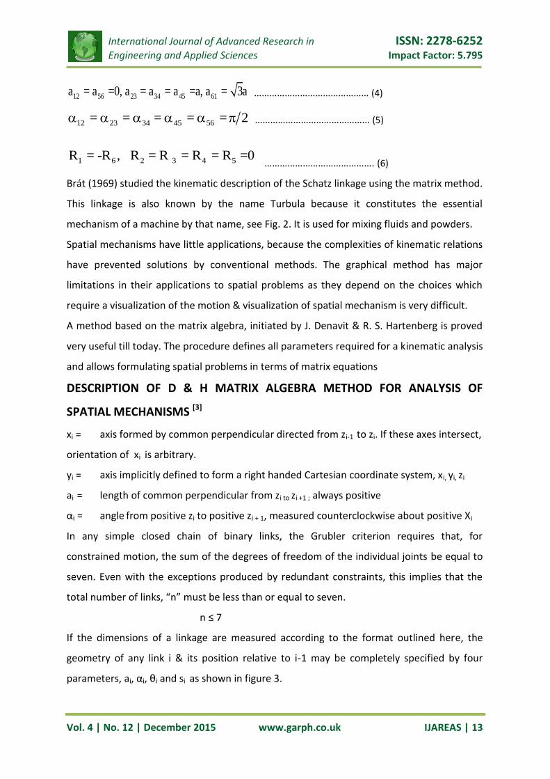
If the dimensions of a linkage are measured according to the format outlined here, the
geometry of any link i & its position relative to i-1 may be completely specified by four
parameters, ai, αi, θi and si as shown in figure 3.
1 6 2 3 4 5 R = -R , R = R = R = R =0
International Journal of Advanced Research in ISSN: 2278-6252
Engineering and Applied Sciences Impact Factor: 5.795
Vol. 4 | No. 12 | December 2015 www.garph.co.uk IJAREAS | 14
Figure 3. D & H Symbolic Notations
These four parameters should be measured for each joint or pair of the linkage according to
the following set of conventions:
i = number of particular joint or pair. Input pair will be taken as 1, and remaining joints
will be numbered consequently around closed loop.
zi = characteristic axis of rotation for pair involved. All the z – axis should be defined
clearly and arbitrary orientation indicated.
xi + 1
θi = angle from positive xi to positive xi + 1 measured counterclockwise about positive zi
si = distance along zi from xi to xi + 1. Takes sign from orientation of positive zi
Once the four parameters have been established for each pair of a linkage, the geometry of
the linkage is completely specified, and can be represented by a symbolic equation of the
form ai, αi, θi and si
2 34
6
1 2 3 4 5 6
1
61
a a0 a 0
a
02 2R R R R R R I2 2 2
02 2 s
s 0 00 0
…………… (7)
Where R1 denotes that pair 1 is a revolute joint with θ1 as variable, P2 denotes that pair 2 is a
prismatic pair with variable s2, and so on. I indicate that the chain is closed. In addition, it
will always be assumed that pair 1 is the input, so that θ1, is the input variable of the
linkage. Although equation 7 is only a symbolic equation describing the geometry of the
International Journal of Advanced Research in ISSN: 2278-6252
Engineering and Applied Sciences Impact Factor: 5.795
Vol. 4 | No. 12 | December 2015 www.garph.co.uk IJAREAS | 15
mechanism, it does lead to a convenient matrix equation. The xi, yi, zi axes define a right
handed Cartesian-coordinate system rigidly attached to link i. The four parameters, ai, αi, θi
and si, fix the position of the coordinate system of link i +1 relative to that of link i. The
relative positions of these two coordinate systems can be stated analytically in terms of a (4
X 4) transformation matrix involving only the four parameters, ai, αi, θi and si,
i i i i i i
i
i i i i i i
i i i
1 0 0 0
a cos cos sin cos sin isinA
a sin sin cos cos cos isin
s 0 sin cos
…………… (8)
Since the mechanism is simple closed loop, the n + 1 coordinate system is identical with
coordinate system 1. This may be expressed in terms of the matrices as,
1 2 n A A A = I …………………………… (9),
where n is the number of links and I is the (4 X 4) unit matrix.
This equation completely describes the geometry of the linkage, and its solutions should
yield a complete displacement analysis, i. e., the values of all pair variables of the linkage in
terms of the fixed parameters and the input variable θ1 (or s1).
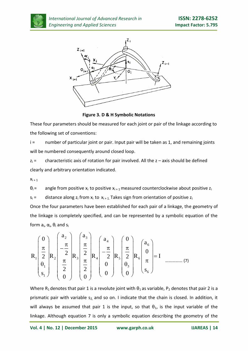
KINEMATIC DESCRIPTION OF 3-D MIXER
Figure 4. 6R 3D Mixer Linkages Showing D & H Notations
The 3-D mixing mechanism mentioned here comprises a six link spatial mechanism which
involves only revolute joints.
The kinematic schematic of this mechanism is shown in figure 4. The main member of the
mechanism is the “Drum” (3), which supports the container with material to be mixed. The
International Journal of Advanced Research in ISSN: 2278-6252
Engineering and Applied Sciences Impact Factor: 5.795
Vol. 4 | No. 12 | December 2015 www.garph.co.uk IJAREAS | 16
drum moves with general spatial motion. The driving member is “Fork” (1) which is same as
member (5). Member (2) and (4) are named as “Yoke” forms the universal joint with drum,
member (3). Member (6) is the fixed base, on which the whole assembly of drum, yokes and
forks is mounted. Attempt is made here to derive the kinematic model of this mechanism
following the Denavit & Hartenberg matrix method.
Characteristic axis of motion at the joint of member (1)-fork1 with member (6)-Fixed base
and characteristic axis of motion at the joint of member (5)-fork2 with member (6)-fixed
base are parallel, (Z1 II Z6). Characteristic axis of motion at the joint of member (1)-fork1
with member (2)-yoke1 and characteristic axis of motion at the joint of member (5)-fork2
with member (4)-yoke2, are initially at right angle and keeps on changing their position
while mechanism is in motion, (Axis Z5 and Axis Z6). Characteristic axis of motion at the joint
of member (2)-yoke1 with member (3)-Cylinder and the characteristic axis of motion at the
joint of member (4)-yoke2 and member (3)-cylinder are always at right angle, (Z3 Z4).
Ordinarily the main members of the mechanism perform only rotational and translatory
motion while the spatial character of the mechanism is caused by connecting members. This
is the case, for example in a Hooke’s joint with the crossed or skewed input and output
shafts.
The coordinate systems at the joint position of each members are assigned according to
Denavit & Hartenberg procedure and four parameters (ai, αi, θi and si,) have been assigned
for each pair of a linkage to specify the geometry of any link i and its position relative to link
i – 1 as shown in figure 4.
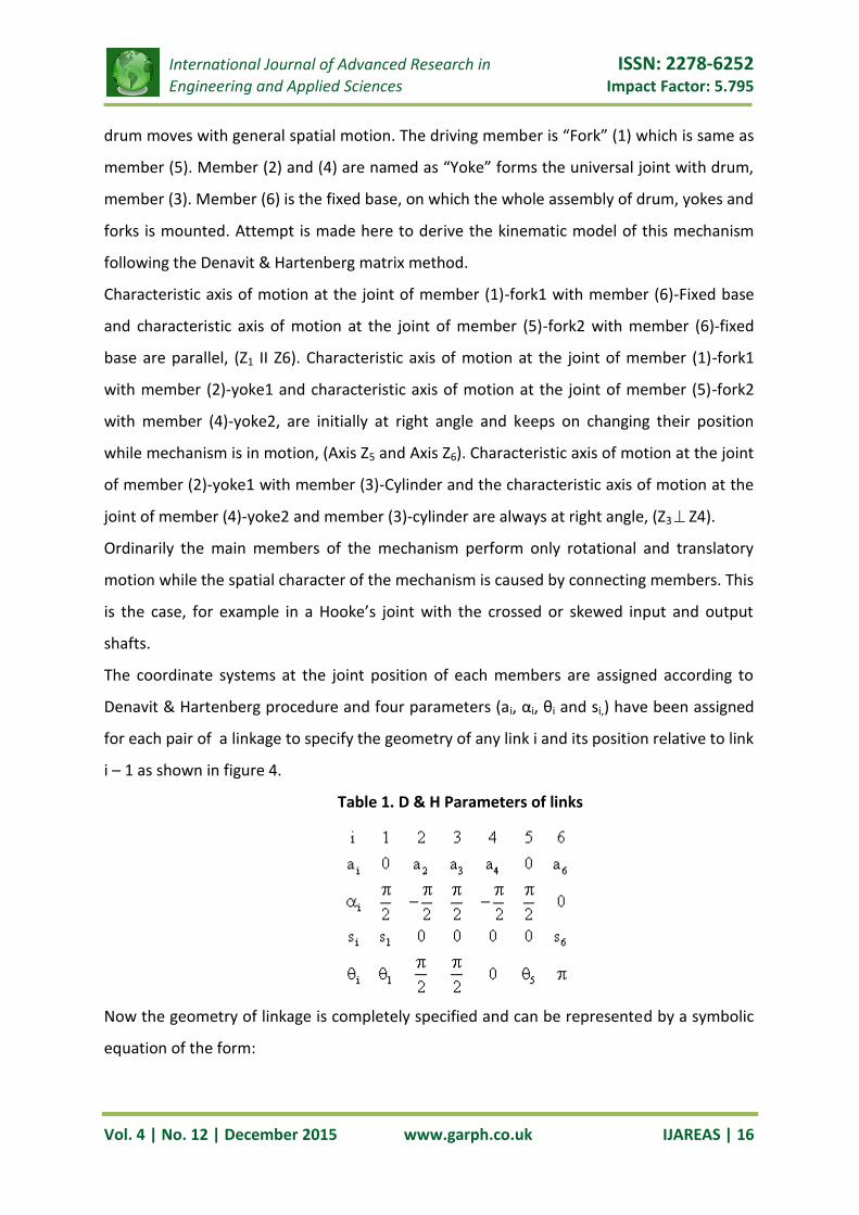
Table 1. D & H Parameters of links
Now the geometry of linkage is completely specified and can be represented by a symbolic
equation of the form:

International Journal of Advanced Research in ISSN: 2278-6252
Engineering and Applied Sciences Impact Factor: 5.795
Vol. 4 | No. 12 | December 2015 www.garph.co.uk IJAREAS | 17
……………….. (10)
Where Ri denotes that pair i is revolute pair with θi as variable. I indicate that the chain is
closed. In addition it is clear that pair 1 is the input pair, so that θ1 is the input variable of
the linkage. The homogeneous transformation matrices relating a link with the adjoining
link are as follows:
……………………………………………….. (11)
………………………………………. (12)
3 3 3 3
3
3 3 3 3
1 0 0 0
a cos cos 0 sinA
a sin sin 0 cos
0 0 1 0
…………………………………………. (13)
4 4 4 4
4
4 4 4 4
1 0 0 0
a cos cos 0 sinA
a sin sin 0 cos
0 0 1 0
………………………………………… (14)
5 5
5
5 5
1 0 0 0
0 cos 0 sinA
0 sin 0 cos
0 0 1 0
…………………………………………………... (15)
2 34
6
1 2 3 4 5 6
1
61
a a0 a 0
a
02 2R R R R R R I2 2 2
02 2 s
s 0 00 0
1 1
1
1 1
1
1 0 0 0
0 cos 0 sinA
0 sin 0 cos
s 0 1 0
2 2 2 2
2
2 2 2 2
1 0 0 0
a cos cos 0 sinA
a sin sin 0 cos
0 0 1 0
International Journal of Advanced Research in ISSN: 2278-6252
Engineering and Applied Sciences Impact Factor: 5.795
Vol. 4 | No. 12 | December 2015 www.garph.co.uk IJAREAS | 18
6 6 6 6
6
6 6 6 6
6
1 0 0 0
a cos cos sin 0A
a sin sin cos 0
d 0 0 1
………………………………………….. (16)
And,
1 2 3 4 5 6A A A A A A I …………………………………………………………… (17)
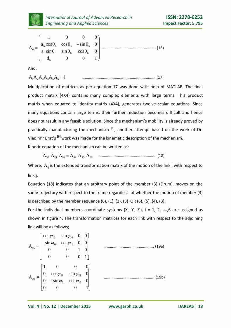
Multiplication of matrices as per equation 17 was done with help of MATLAB. The final
product matrix (4X4) contains many complex elements with large terms. This product
matrix when equated to identity matrix (4X4), generates twelve scalar equations. Since
many equations contain large terms, their further reduction becomes difficult and hence
does not result in any feasible solution. Since the mechanism’s mobility is already proved by
practically manufacturing the mechanism [6], another attempt based on the work of Dr.
Vladim’r Brat’s [5] work was made for the kinematic description of the mechanism.
Kinetic equation of the mechanism can be written as:
32 21 16 34 45 56A A A A A A ……………………………………………… (18)
Where, ijA is the extended transformation matrix of the motion of the link i with respect to
link j.
Equation (18) indicates that an arbitrary point of the member (3) (Drum), moves on the
same trajectory with respect to the frame regardless of whether the motion of member (3)
is described by the member sequence (6), (1), (2), (3) OR (6), (5), (4), (3).
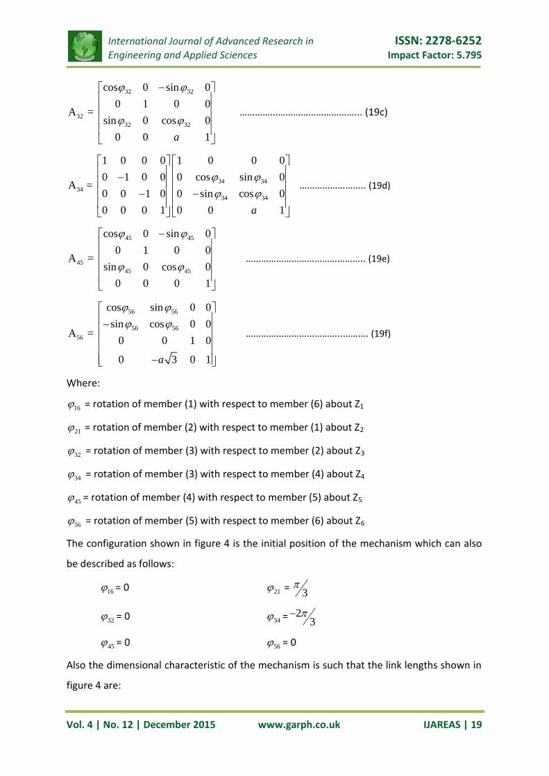
For the individual members coordinate systems (Xi, Yi, Zi), i = 1, 2, ….,6 are assigned as
shown in figure 4. The transformation matrices for each link with respect to the adjoining
link will be as follows;
16 16
16 16
16
cos sin 0 0
sin cos 0 0A
0 0 1 0
0 0 0 1
……………………………………….. (19a)
21 21
21
21 12
1 0 0 0
0 cos sin 0A =
0 sin cos 0
0 0 0 1
……………………………………….. (19b)
International Journal of Advanced Research in ISSN: 2278-6252
Engineering and Applied Sciences Impact Factor: 5.795
Vol. 4 | No. 12 | December 2015 www.garph.co.uk IJAREAS | 19
32 32
32
32 32
cos 0 sin 0
0 1 0 0A =
sin 0 cos 0
0 0 1a
………………………………………... (19c)
34 34
34
34 34
1 0 0 0 1 0 0 0
0 1 0 0 0 cos sin 0A =
0 0 1 0 0 sin cos 0
0 0 0 1 0 0 1a
…………………….. (19d)
45 45
45
45 45
cos 0 sin 0
0 1 0 0A =
sin 0 cos 0
0 0 0 1
……………………………………….. (19e)
56 56
56 56
56
cos sin 0 0
sin cos 0 0A =
0 0 1 0
0 3 0 1a
………………………………..………. (19f)
Where:
16 = rotation of member (1) with respect to member (6) about Z1
21 = rotation of member (2) with respect to member (1) about Z2
32 = rotation of member (3) with respect to member (2) about Z3
34 = rotation of member (3) with respect to member (4) about Z4
45 = rotation of member (4) with respect to member (5) about Z5
56 = rotation of member (5) with respect to member (6) about Z6
The configuration shown in figure 4 is the initial position of the mechanism which can also
be described as follows:
16 = 0 21 = 3
32 = 0 34 = 23
45 = 0 56 = 0
Also the dimensional characteristic of the mechanism is such that the link lengths shown in
figure 4 are:

International Journal of Advanced Research in ISSN: 2278-6252
Engineering and Applied Sciences Impact Factor: 5.795
Vol. 4 | No. 12 | December 2015 www.garph.co.uk IJAREAS | 20
a2 = a3 = a4 = a and a6 = 3a
Substituting the initial position values in equation (19) and substituting equation (19a) to
equation (19f) in equation (18) product matrices of the following form is obtained.
4 4 4 4X X
a b
By comparing the corresponding terms twelve scalar equations are obtained:
32 16 32 21 16 45 56cos cos sin sin sin cos cos ………………………..………….. (20)
32 16 32 21 16 45 56cos sin sin sin cos cos sin ………………………………………. (21)
32 21 45sin cos sin ………………………………………………………….……………….…. (22)
21 16 34 56 34 45 56cos sin cos sin sin sin cos ………………..………………… (23)
21 16 34 56 34 45 56cos cos cos cos sin sin sin ……………..……………………. (24)
21 34 45sin sin cos ……………………………………………………………….…………………. (25)
32 16 32 21 16 34 56 34 45 56sin cos cos sin sin sin sin cos sin cos …. (26)
32 16 32 21 16 34 56 34 45 56sin sin cos sin cos sin cos cos sin sin ……. (27)
32 21 34 45cos cos cos cos ……………………………………………………..…………..… (28)
21 16 45 56sin sin sin cos ………………………………………………………..……………….. (29)
21 16 45 56sin cos sin sin 3 ………………………………………………………………..….. (30)
21 45cos cos ……………………………………….………………………………………………….…. (31)
Equations (20) to (31) are useful to find out rotation of angles 21, 32, 34, 45, 56 and as a
function of input angle 16 . Dependence of the remaining angles upon the input angle 16 is
as follows:
21 163sin cos
2
………………………………………………………….. (32a)
2
21 161cos 4 3cos
2 …………………………………………..……..(32b)
45 2
16
1cos4 3cos
………………………………………………....... (33a)
1645 2
16
3 sinsin
4 3cos
………………………………..……….. (33b)
International Journal of Advanced Research in ISSN: 2278-6252
Engineering and Applied Sciences Impact Factor: 5.795
Vol. 4 | No. 12 | December 2015 www.garph.co.uk IJAREAS | 21
2
34 163cos 1 cos
2 …………………………………….…………. (34a)
2
34 16 163sin cos 4 3cos
2
………………………………. (34b)
2 2
32 16 16cos 3cos 2 4 3cos ……………………………… (35a)
2
32 16 16sin 2 3 sin 4 3cos ………………………………. (35b)
2
56 16 16cos cos 4 3cos …………………………………..…………. (36a)
2
56 16 16sin 2sin 4 3cos ………………………………….. (36b)
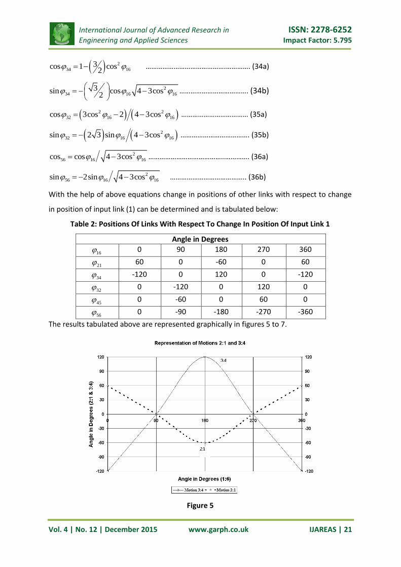
With the help of above equations change in positions of other links with respect to change
in position of input link (1) can be determined and is tabulated below:
Table 2: Positions Of Links With Respect To Change In Position Of Input Link 1
Angle in Degrees
16 0 90 180 270 360
21 60 0 -60 0 60
34 -120 0 120 0 -120
32 0 -120 0 120 0
45 0 -60 0 60 0
56 0 -90 -180 -270 -360
The results tabulated above are represented graphically in figures 5 to 7.
Figure 5

International Journal of Advanced Research in ISSN: 2278-6252
Engineering and Applied Sciences Impact Factor: 5.795
Vol. 4 | No. 12 | December 2015 www.garph.co.uk IJAREAS | 22
Figure 6
Figure 7
CONCLUSION:
A mixing machine described here employs a very interesting mechanism. Attempt is made
here to describe general kinematics of the six link mechanism involving only revolutes, using
matrix method. As discussed here that a spatial mechanism containing only revolutes is
derived from the seven link kinematics chain. However mechanism described here has only
International Journal of Advanced Research in ISSN: 2278-6252
Engineering and Applied Sciences Impact Factor: 5.795
Vol. 4 | No. 12 | December 2015 www.garph.co.uk IJAREAS | 23
six links including the fixed base. If the link lengths are selected arbitrary, then the
mechanism will result in immobility with no degrees of freedom. Mobility of the mechanism
is because of specific linear dimensions only. The mobility of the mechanism is proved with
this kinematics description. In case of immobility of the mechanism, equations (20) to (31)
would have produced contradictory results. Additionally, mobility can also be proved with
the help of CAD software & also by actually making the working model of the machine.
REFERENCES:
1. Yan CHEN, Design of Structural Mechanisms, A dissertation submitted for the
degree of Doctor of Philosophy in the Department of Engineering Science at the
University of Oxford, St Hugh’s College Trinity Term 2003
2. Constantinos Mavroidis, Assistant Professor, Michael Beddows, Research Assistant,
“A spatial over-constrained mechanism that can be used in practical applications”
3. J. J. Uicker Jr., J. Denavit, R. S.Hartenberg, Journal of Applied Mechanics, June 1964
“An Iterative Method For The Displacement Analysis Of Spatial Mechanisms”
4. Albert J. Shih & Hong-Sen Yan, Mechanism & Machine Theory 37 (2002) 61 – 73
“Synthesis of a single loop, over-constrained six revolute joint spatial mechanism for
two position cylindrical rigid body guidance”
5. Dr. Vladim’r Brǎt, CSc, Journal of Mechanism Volume 4, 1969 “A Six Link Spatial
Mechanism”
6. Vandan Kamlakar Gundale, November 15 Volume 3 Issue 11, “Development Of
Working Model of 3-D Mixer”, International Journal on Recent and Innovation
Trends in Computing and Communication (IJRITCC), ISSN: 2321-8169, PP: 6427 -
6431


![Kinematic Analysis of A 3-DOF Parallel Mechanism for ... · dance with the Kutzbach-Gruebler criterion [2], λ=6, n=8, ... Kinematic Analysis of A 3-DOF Parallel Mechanism for Milling](https://static.fdocuments.net/doc/165x107/5b1c01a67f8b9a46258f3522/kinematic-analysis-of-a-3-dof-parallel-mechanism-for-dance-with-the-kutzbach-gruebler.jpg)


![A novel six-degrees-of-freedom series-parallel … · A novel six-degrees-of-freedom series-parallel manipulator ... Kutzbach criterion [19], is capable to realize six degrees of](https://static.fdocuments.net/doc/165x107/5b79f3c77f8b9a703b8ebdd5/a-novel-six-degrees-of-freedom-series-parallel-a-novel-six-degrees-of-freedom.jpg)


