Kinematic Analysis and Experimental Verification on the ... · PDF fileKINEMATIC ANALYSIS AND...
9
1 Copyright © 2009 by ASME Proceedings of the ASME 2009 International Design Engineering Technical Conferences & Computers and Information in Engineering Conference IDETC/CIE 2009 August 30 - September 2, 2009, San Diego, California, USA DETC2009-87076 KINEMATIC ANALYSIS AND EXPERIMENTAL VERIFICATION ON THE STEERING CHARACTERISTICS OF A TWO ACTUATED SPOKE WHEEL ROBOT WITH A TAIL Ping Ren RoMeLa: Robotics & Mechanisms Laboratory Mechanical Engineering Department Virginia Tech Blacksburg, Virginia 24061 Email: [email protected] J. Blake Jeans RoMeLa:Robotics & Mechanisms Laboratory Mechanical Engineering Department Virginia Tech Blacksburg, Virginia 24061 E-mail: [email protected] Dennis Hong 1 RoMeLa: Robotics & Mechanisms Laboratory Mechanical Engineering Department Virginia Tech Blacksburg, Virginia 24061Email: [email protected] 1 Address all correspondence to this author. ABSTRACT Intelligent Mobility Platform with Active Spoke System (IMPASS) is a novel wheel-leg hybrid robot that can walk in unstructured environments by stretching in or out three independently actuated spokes of each wheel. This paper firstly introduces the latest prototype of the robot that has two actuated spoke wheels and one tail. Due to its metamorphic configurations, this robot can be considered as a mechanism with variable topologies (MVTs). The mobility analysis in previous work is briefly summarized and then the transformation relationships between different configurations are addressed. Thus, the motions of the robot on the ground, such as steering, straight-line walking and other combinations can be uniformly interpreted as series of configuration transformations. In order to maintain the coherence between the coordinate setups in different configurations, previous rigid body kinematic models are modified. Two types of turning, steady state turning and turning gait transition, are revisited with the characteristics being refined. Finally, the hardware design of the prototype is demonstrated, followed by the experimental verifications of the characteristic motions. The work presented in this paper lays the kinematics foundation for the future research on the motion planning algorithms of IMPASS. 1. INTRODUCTION Leg-wheel hybrid robots have been drawing more attention since they have the advantages of both legs and wheels. Legged locomotion is more adaptable to a wide range of unstructured grounds but the complicated mechanism of the legs is very difficult to implement. On the other hand, wheeled locomotion is fast and efficient but it tends to be limited to relatively smooth terrain. Therefore, in order to create a walking machine that combines the benefits of both locomotion schemes, spoke wheels or similar mechanisms can be good candidates. Previous mobile platforms that utilize spoke wheels mainly include RHex [1] and Whegs TM [2]. RHex is a compliant- legged hexapod with a simple clock-driven open-loop tripod gait. It is different from other robots in that each of its legs rotates in full circles acting as a single spoke wheel. The Whegs TM series of robots is another derivation of the spoke wheel concept that utilizes compliant tri-spoke configuration in each wheel. (a) (b) Figure.1 Concept design and the prototype of IMPASS Proceedings of the ASME 2009 International Design Engineering Technical Conferences & Computers and Information in Engineering Conference IDETC/CIE 2009 August 30 - September 2, 2009, San Diego, California, USA DETC2009-87076 Downloaded From: http://proceedings.asmedigitalcollection.asme.org/ on 05/02/2015 Terms of Use: http://asme.org/terms
Transcript of Kinematic Analysis and Experimental Verification on the ... · PDF fileKINEMATIC ANALYSIS AND...
1 Copyright © 2009 by ASME
Proceedings of the ASME 2009 International Design Engineering Technical Conferences & Computers and Information in Engineering Conference
IDETC/CIE 2009 August 30 - September 2, 2009, San Diego, California, USA
DETC2009-87076
KINEMATIC ANALYSIS AND EXPERIMENTAL VERIFICATION ON THE STEERING
CHARACTERISTICS OF A TWO ACTUATED SPOKE WHEEL ROBOT WITH A TAIL
Ping Ren RoMeLa: Robotics & Mechanisms
Laboratory Mechanical Engineering Department
Virginia Tech Blacksburg, Virginia 24061
Email: [email protected]
J. Blake Jeans RoMeLa:Robotics & Mechanisms
Laboratory Mechanical Engineering Department
Virginia Tech Blacksburg, Virginia 24061
E-mail: [email protected]
Dennis Hong1
RoMeLa: Robotics & Mechanisms Laboratory
Mechanical Engineering Department Virginia Tech
Blacksburg, Virginia 24061Email: [email protected]
1 Address all correspondence to this author.
ABSTRACT Intelligent Mobility Platform with Active Spoke System
(IMPASS) is a novel wheel-leg hybrid robot that can walk in unstructured environments by stretching in or out three independently actuated spokes of each wheel. This paper firstly introduces the latest prototype of the robot that has two actuated spoke wheels and one tail. Due to its metamorphic configurations, this robot can be considered as a mechanism with variable topologies (MVTs). The mobility analysis in previous work is briefly summarized and then the transformation relationships between different configurations are addressed. Thus, the motions of the robot on the ground, such as steering, straight-line walking and other combinations can be uniformly interpreted as series of configuration transformations. In order to maintain the coherence between the coordinate setups in different configurations, previous rigid body kinematic models are modified. Two types of turning, steady state turning and turning gait transition, are revisited with the characteristics being refined. Finally, the hardware design of the prototype is demonstrated, followed by the experimental verifications of the characteristic motions. The work presented in this paper lays the kinematics foundation for the future research on the motion planning algorithms of IMPASS.
1. INTRODUCTION Leg-wheel hybrid robots have been drawing more attention since they have the advantages of both legs and wheels. Legged locomotion is more adaptable to a wide range of unstructured grounds but the complicated mechanism of the legs is very difficult to implement. On the other hand, wheeled locomotion is fast and efficient but it tends to be limited to relatively smooth terrain. Therefore, in order to create a walking machine that combines the benefits of both
locomotion schemes, spoke wheels or similar mechanisms can be good candidates.
Previous mobile platforms that utilize spoke wheels mainly include RHex [1] and Whegs
TM [2]. RHex is a compliant-
legged hexapod with a simple clock-driven open-loop tripod gait. It is different from other robots in that each of its legs rotates in full circles acting as a single spoke wheel. The Whegs
TM series of robots is another derivation of the spoke
wheel concept that utilizes compliant tri-spoke configuration in each wheel.
(a)
(b)
Figure.1 Concept design and the prototype of IMPASS
Proceedings of the ASME 2009 International Design Engineering Technical Conferences & Computers and Information in Engineering Conference
IDETC/CIE 2009 August 30 - September 2, 2009, San Diego, California, USA
DETC2009-87076
Downloaded From: http://proceedings.asmedigitalcollection.asme.org/ on 05/02/2015 Terms of Use: http://asme.org/terms

2 Copyright © 2009 by ASME
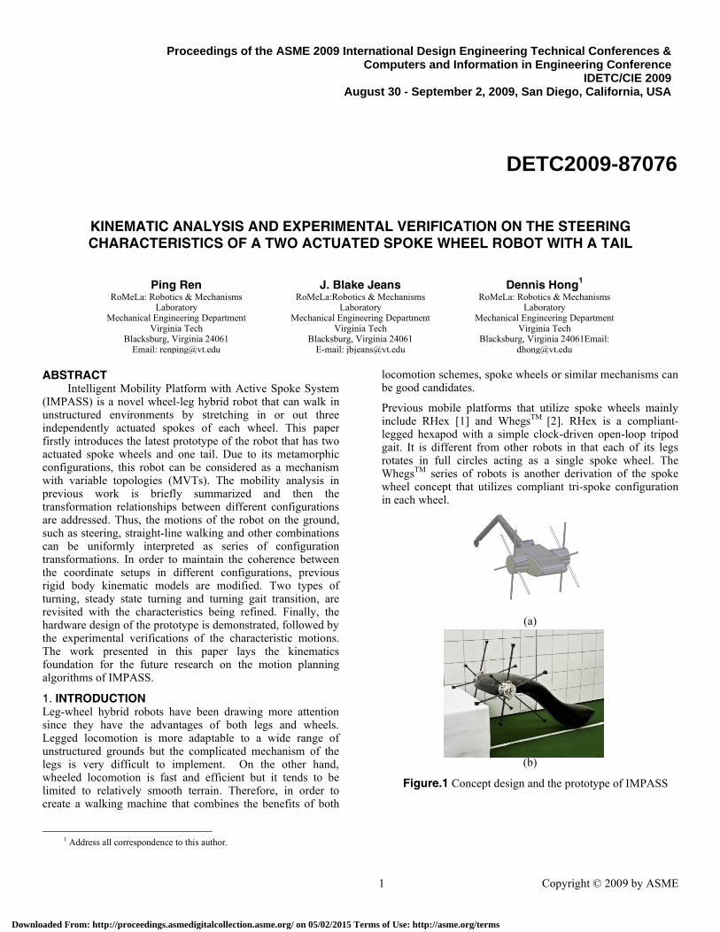
As shown in Figure 1(a), the Intelligent Mobility Platform with Active Spoke System (IMPASS) robot, currently under development in RoMeLa: Robotics and Mechanisms Laboratory at Virginia Tech, also adopts the concept of actuated spoke wheels. Compared with the spoke wheel robots that preceded IMPASS, the uniqueness of IMPASS mainly lies on the novel configuration of the spoke wheels (six spokes per wheel unit, compared to three for Whegs
TM and only one
for RHex) and its ability to stretch each spoke in or out intelligently. The prototype demonstrated in Figure 1(b) has
two actuated spoke wheels and one passive tail. The compliant spokes are made of carbon fiber and set 60 degrees from each other. It is designed to walk on various terrains, cross over obstacles, climb up steps and so on. Since the two spoke wheels are actuated by a single axle, the robot can also rotate the spoke wheels on smooth surfaces like conventional wheeled robots. Preliminary mechanical designs, kinematic analysis on the motions of straight-line walking, steady state turning and turning transition can be found in [3-5].
Figure.2 Transformation relationships between all contact modes
1 d.o.f
2-1, parallel, equal
0 d.o.f
2-1, parallel, unequal
2 d.o.f
1-1, parallel, unequal
0 d.o.f
2-2, parallel, unequal
2 d.o.f
1-1, skew
0 d.o.f
3-3, parallel equal
1 d.o.f
2-2, parallel, equal
2 d.o.f + 1 instantaneous d.o.f
1-1, parallel, equal
Downloaded From: http://proceedings.asmedigitalcollection.asme.org/ on 05/02/2015 Terms of Use: http://asme.org/terms
3 Copyright © 2009 by ASME
The content of this paper is organized as: the variable mobility of the spoke wheel robot is addressed in Section 2; followed by the modified kinematic models in Section 3. In Section 4, the characteristics of steady state turning and turning gait transition are discussed. Section 5 mainly describes the hardware design of the prototype and the experimental verifications are presented in Section 6.
2. MECHANISM WITH VARIABLE TOPOLOGIES Apparently, as IMPASS moves on smooth surfaces, its body is always connected to the ground through multiple actuated spokes. By treating the ground as the base, the actuating axle that connects the two wheels as the body, the spokes as the limbs, this particular robotic system forms a parallel mechanism with variable topologies, i.e., the robot is capable of changing its kinematic configuration by changing the scheme of the actuated spokes’ contact with the ground. As far as the prototype shown in Figure 1 is concerned, each of its configurations is characterized by the contact case of its spokes, thus is termed as a contact mode in the following discussions.
The variable mobility in all contact modes was previously investigated in [6]. A few assumptions made ahead include: all the links are rigid, the two wheels are always in the same phase, and no slip or bounce occurs at the contact points. The results are summarized in Figure 2, with the blue arrows denoting the bidirectional transformation relationships between different modes. In Figure 2, the terminology “n1-n2” is used to represent each characteristic contact mode, which indicates the number of the contact spokes in the left and right wheel without losing generality. The term “parallel, equal/unequal” in the figure indicates that the geometrically parallel contact spokes in this mode are of equal/unequal length. The term “skew” indicates that in this mode the left contact spoke is skew to the right contact spoke. Due to the existence of kinematically parallel structures, some contact modes are inherently over-constrained mechanisms. Thus, the Modified Grübler-Kutzbach criterion in [7,8] is adopted to identify the correct number of d.o.f under these contact modes. The number of d.o.f is shown above each mode in Figure 2.
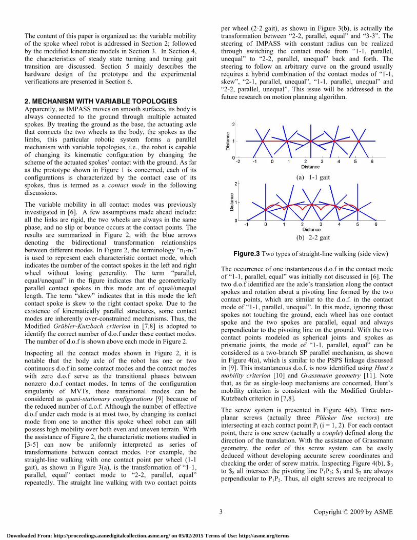
Inspecting all the contact modes shown in Figure 2, it is notable that the body axle of the robot has one or two continuous d.o.f in some contact modes and the contact modes with zero d.o.f serve as the transitional phases between nonzero d.o.f contact modes. In terms of the configuration singularity of MVTs, these transitional modes can be considered as quasi-stationary configurations [9] because of the reduced number of d.o.f. Although the number of effective d.o.f under each mode is at most two, by changing its contact mode from one to another this spoke wheel robot can still possess high mobility over both even and uneven terrain. With the assistance of Figure 2, the characteristic motions studied in [3-5] can now be uniformly interpreted as series of transformations between contact modes. For example, the straight-line walking with one contact point per wheel (1-1 gait), as shown in Figure 3(a), is the transformation of “1-1, parallel, equal” contact mode to “2-2, parallel, equal” repeatedly. The straight line walking with two contact points
per wheel (2-2 gait), as shown in Figure 3(b), is actually the transformation between “2-2, parallel, equal” and “3-3”. The steering of IMPASS with constant radius can be realized through switching the contact mode from “1-1, parallel, unequal” to “2-2, parallel, unequal” back and forth. The steering to follow an arbitrary curve on the ground usually requires a hybrid combination of the contact modes of “1-1, skew”, “2-1, parallel, unequal”, “1-1, parallel, unequal” and “2-2, parallel, unequal”. This issue will be addressed in the future research on motion planning algorithm.
(a) 1-1 gait
(b) 2-2 gait
Figure.3 Two types of straight-line walking (side view) The occurrence of one instantaneous d.o.f in the contact mode of “1-1, parallel, equal” was initially not discussed in [6]. The two d.o.f identified are the axle’s translation along the contact spokes and rotation about a pivoting line formed by the two contact points, which are similar to the d.o.f. in the contact mode of “1-1, parallel, unequal”. In this mode, ignoring those spokes not touching the ground, each wheel has one contact spoke and the two spokes are parallel, equal and always perpendicular to the pivoting line on the ground. With the two contact points modeled as spherical joints and spokes as prismatic joints, the mode of “1-1, parallel, equal” can be considered as a two-branch SP parallel mechanism, as shown in Figure 4(a), which is similar to the PSPS linkage discussed in [9]. This instantaneous d.o.f. is now identified using Hunt’s mobility criterion [10] and Grassmann geometry [11]. Note that, as far as single-loop mechanisms are concerned, Hunt’s mobility criterion is consistent with the Modified Grübler-Kutzbach criterion in [7,8].
The screw system is presented in Figure 4(b). Three non-planar screws (actually three Plücker line vectors) are intersecting at each contact point Pi (i = 1, 2). For each contact point, there is one screw (actually a couple) defined along the direction of the translation. With the assistance of Grassmann geometry, the order of this screw system can be easily deduced without developing accurate screw coordinates and checking the order of screw matrix. Inspecting Figure 4(b), $3 to $8 all intersect the pivoting line P1P2; $1 and $2 are always perpendicular to P1P2. Thus, all eight screws are reciprocal to
Downloaded From: http://proceedings.asmedigitalcollection.asme.org/ on 05/02/2015 Terms of Use: http://asme.org/terms
4 Copyright © 2009 by ASME
one straight line P1P2 and form a screw system with order 5, rather than 6. Hunt’s mobility criterion states:
g
i
ifgndM1
1 (1)
where n is the number of links, g the number of joints and fi the d.o.f of joint i, d is the order of the screw system. In this case, d is taken as 5, with n, g as 4; M is then equal to 3, which indicates that this contact mode has 3 d.o.f. Besides the two continuous d.o.f mentioned above, the additional instantaneous d.o.f is actually a rotation of the axle link about the direction perpendicular to the plane formed by the axle and the two contact spokes. The results can be verified by using the close-loop twist equations of the two-branch SP parallel mechanism. The details are omitted here.
x
yz
(a) Two-branch, single-loop, SP parallel mechanism
(b) Screw system
Figure.4 Two-branch SP parallel mechanism and its screw system
Compare the contact mode of “1-1, parallel, equal” to “1-1, parallel, unequal”, the former is actually a special case of the latter with an extra d.o.f and two equal spokes. Thus, “1-1, parallel, equal” can be considered as a quasi-uncertainty configuration with respect to “1-1, parallel, equal” [9]. This instantaneous d.o.f can be constrained as long as the two contact spokes are always equal and actuated simultaneously. If compliant spokes are used instead of perfectly rigid spokes, then by differentiating the lengths of two contact spokes, this d.o.f could become continuous with certain range without leading too much slipping between the spoke tips and the ground. This phenomenon is described in Section 6.
3. MODIFIED KINEMATIC MODELS
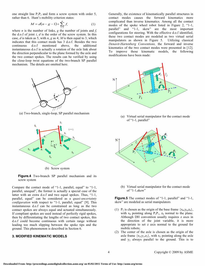
Generally, the existence of kinematically parallel structures in contact modes causes the forward kinematics more complicated than inverse kinematics. Among all the contact modes of the spoke wheel robot listed in Figure 2, “1-1, parallel” and “1-1, skew” are the most important configurations for steering. With the effective d.o.f identified, these two contact modes are modeled as two virtual serial manipulators as shown in Figure 5. Utilizing classical Denavit-Hartenberg Conventions, the forward and inverse kinematics of the two contact modes were presented in [12]. To improve those kinematic models, the following modifications have been made:
(a) Virtual serial manipulator for the contact mode of “1-1, parallel”
(b) Virtual serial manipulator for the contact mode of “1-1,skew”
Figure.5 The contact modes of “1-1, parallel” and “1-1, skew” are modeled as serial manipulators
(1) P2 is chosen as the origin of the base frame {x0,y0,z0},
with x0 pointing along P2P1, z0 normal to the plane. Although DH convention usually requires z axes in the direction of the joint variable, it is more appropriate to set z axis normal to the ground for mobile robots;
(2) The center of the axle is chosen as the origin of the axle frame {x2,y2,z2}, with x2 pointing along the axle and y2 always parallel to the ground. This is to
Downloaded From: http://proceedings.asmedigitalcollection.asme.org/ on 05/02/2015 Terms of Use: http://asme.org/terms

5 Copyright © 2009 by ASME
maintain the coherence of {x2,y2,z2} in different “1-1” contact modes.
The coordinate setups after modifications are displayed in Figure 6. The relative positions and orientations of adjacent frames are identified either using DH parameters or by geometric inspection. Virtual joint variables and necessary geometric parameters in this figure can determined through spoke lengths and wheel phase angles [12].
(a) Coordinates setup for the contact mode of “1-1, parallel”
(b) Coordinates setup for the contact mode of “1-1, skew”
Figure.6 Two virtual serial manipulators with coordinates systems
With the assistance of these frames, the forward kinematics of the two “1-1” contact modes now can be solved using homogeneous transformation matrices. Since these two modes only have two effective d.o.f, either {x, y} or {x, z} components in the origin vector of frame {x2,y2,z2} expressed in {x0,y0,z0} are sufficient to determine {θ1, d2} in “1-1, parallel” or {θ1, θ2} in “1-1, skew”. With {θ1, d2} or {θ1, θ2} obtained, the spoke lengths and wheel angles can be calculated, thus solving the inverse kinematics.
Examining the transformation relationships in Figure 2, the modes with three contact spokes (2-1, parallel, equal; 2-1,
parallel, unequal) and four contact spokes (2-2, parallel, equal; 2-2, parallel, unequal) serve as the transitional phases between
“1-1” contact modes. Since three non-collinear points are sufficient to determine a plane, the forward kinematics in these transitional contact modes can be solved with the same procedures as follows.
First, choose three non-collinear contact spokes and establish an axle frame {x’2, y’2 ,z’2} as shown in Figure 7, with the origin set at the center of the axle, x’2 axis along the direction of the axle. The direction of z’2 is taken such that the twist angle between z’2 and the three contact spokes are all 30 degrees.
Figure.7 Coordinates setup for contact modes with three or more than three contact spokes
Then, with the lengths of the three contact spokes specified, the position vectors of the contact points Pi (i = 1,2,3) in {x’2, y’2 ,z’2} can be determined. These three vectors uniquely decide on the ground plane P1P2P3 in{x’2, y’2 ,z’2}. Thus, any
reference point on this plane can be used to create a frame. As shown in Figure 7, a frame {x0, y0 ,z0} is formed with x0 along P3P2 and z0 normal to the plane. Such an arrangement of the three axes is consistent with those in Figure 6 (a) and (b). The transformation matrix from {x’2, y’2 ,z’2} to {x0, y0 ,z0} is developed with:
13P0z0y0xTbPzNyNxNT
xzy
PP/PPxz
PP/PPx
000
31300
32320
1000
44
)02'(
1000
44
2'0
1
(2)
The orientation vectors in '2
0T must be modified to maintain
consistence with the axle frames defined in “1-1” contact modes. As shown follows:
1000
44
20
100
bPzNyNxNT
yNxNzN
xNyN
xN
xN
(3)
Downloaded From: http://proceedings.asmedigitalcollection.asme.org/ on 05/02/2015 Terms of Use: http://asme.org/terms

6 Copyright © 2009 by ASME
Therefore, the forward kinematics in contact modes with three or more than three contact spokes is solved. As for inverse kinematics, if the position and orientation of the axle are given, then, similar to “1-1” contact modes, the position vector of origin in {x2,y2,z2} can be used to solve for the lengths of the contact spokes. This is because the contact mode with three or more than three contact spokes can be treated as a combination of multiple “1-1” modes.
The forward and inverse kinematics discussed above can be utilized to generate an algorithm to monitor continuously the steering behaviors of the spoke wheel robot on even ground. Although kinematic analysis is intended to model those contact modes as complete as possible, the dependence on 4 by 4 homogeneous matrices operations usually requires relatively large amount of computation. However, in actual applications, vector operations that are the most necessary can be extracted from matrices operations, thus reducing the total amount of calculation. For example, it is possible to monitor just the position of the axle or contact points instead of all information. Discrete monitoring could also be used which only calculates the position and orientation of the axle in transitional contact modes.
4. CHARACTERISTICS OF STEADY STATE TURNING
AND TURNING GAIT TRANSITION The steady state turning addressed in [5] is a discrete motion that changes the heading direction of the spoke wheel robot step by step. This type of steering is none other than the switching of the contact mode from “1-1, parallel, unequal” to “2-2, parallel, unequal” back and forth. In this turning, all the left and right contact spokes keep both constant difference and proportion coefficient. As shown in Figure 8(a), in each “2-2, parallel, unequal” mode, the line along the axle of the robot and the two pivoting lines on the ground all intersect at one point. Therefore, in steady state turning, all the contact points on the ground lie on concentric circles with the intersecting point as the center, which is indicated in Figure 8(b).
A1
A2
B1
B2
O
(a) Three lines intersect at the same point in “2-2, parallel unequal”
xN
yNO
Δφ1
Δφ2
A1A2
B2
B1
C2
C1
l
kl
g e
g
e
h
f
c
kc
(b) Top view of steady state turning
Figure.8 Discrete motion of steady state turning
In Figure 8(b), A1, A2, B1, B2, C1, C2… are the contact points on the ground, with the origin of planar reference frame {xN, yN} O set at the center of circles. Lower case letters are used to denote the lengths of the line segments. Without losing generality, assume all left spokes in this motion are of the same length l and all right spokes the same length kl, where k is a constant proportion coefficient greater than 1. Then, apparently, the robot will make a left turn as indicated in Figure 8(b). The distance of A1A2, i.e. e, and the turning radius g is determined as:
1
22
k
eg
wlkle (4)
where w is the length of the axle. Using the directions perpendicular to pivoting lines as the reference of the robot’s heading (indicated with the arrows in Figure 8b), then the change of the heading angle is derived as:
2
221
2
2cos
g
lg
(5)
The case discussed above can be extended to a more general scenario with the length of the next left contact spoke as jl and next right spoke kjl, where j is a positive proportion coefficient and cannot exceed the physical limit of the spoke length. In such a case, Eq.(4) and (5) are modified as:
1
22
k
fh
wjlkjlf (6)
and
Downloaded From: http://proceedings.asmedigitalcollection.asme.org/ on 05/02/2015 Terms of Use: http://asme.org/terms
7 Copyright © 2009 by ASME
ef
ckcfe
jlljlc
wlkle
2
)(cos
2221
222
22
(7)
Examining Eq.(4) to (7), one can find that, if j, the ratio of the next contact spoke to the current contact spoke is not equal to 1, then the turning radius and will be changed. Also, in
the “1-1, parallel, unequal” modes, the proportion coefficient k of the right spoke to the left can be changed by stretching the spokes in or out simultaneously, thus shifting the center of the circle to another location along the pivoting line.
Utilizing such characteristics of steady state turning, the mobile spoke wheel robot can travel discretely from one circle to another, with the circle centers always at the side of the shorter spokes. However, only steady state turning is not sufficient to track any paths on the ground. Therefore, a turning gait transition is required.
Turning gait transition is a series of mode transformations from “1-1, parallel, unequal/equal”, through “2-1, parallel, unequal/equal”, to “1-1, skew” [5], as shown in Figure 2. Utilizing the two d.o.f in “1-1, skew”, the robot can transfer discretely from its current path to a straight-line path or to another circular path with the center located at the other side of the robot, thus compensating for the deficiency of steady state turning.
Combining steady state turning, turning gait transition and straight-line walking, the general steering of the spoke wheel robot on even ground can be developed. Again, the planning issue will be addressed in future research.
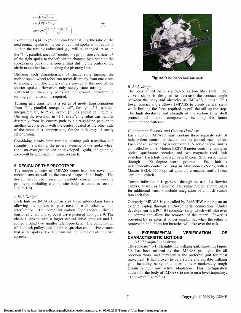
5. DESIGN OF THE PROTOTYPE The unique abilities of IMPASS come from the novel hub mechanisms as well as the curved shape of the body. The design has evolved from a hub feasibility concept to a working prototype, including a composite body structure as seen in Figure 1(b). A.Hub Design Each hub on IMPASS consists of three interlocking layers allowing the spokes to pass next to each other without interference. The compliant carbon fiber spokes utilize a tensioned chain and sprocket drive pictured in Figure 9. The chain is driven with a larger central drive sprocket and is routed around two smaller idler sprockets. The combination of the black pulleys and the three-sprocket chain drive ensures that as the spokes flex the chain will not come off of the drive sprocket.
Figure.9 IMPASS hub internals B. Body design The body of IMPASS is a curved carbon fiber shell. The curved shape is designed to decrease the contact angle between the body and obstacles as IMPASS climbs. This lower contact angle allows IMPASS to climb vertical steps while limiting the force required to pull the tail up the step. The high durability and strength of the carbon fiber shell protects all internal components, including the future computer and batteries. C. Actuators, Sensors, and Control Hardware Each hub on IMPASS must contain three separate sets of independent control hardware; one to control each spoke. Each spoke is driven by a Portescap 17N servo motor, and is controlled by an AllMotion EZSV10 motor controller using an optical quadrature encoder, and two magnetic reed limit switches. Each hub is driven by a Maxon RE30 servo motor through a 90 degree worm gearbox. Each hub is independently controlled using an AllMotion EZSV23, with a Maxon HEDL 5540 optical quadrature encoder and a linear cam limit switch.
Terrain information is gathered through the use of a firewire camera, as well as a Hokuyo laser range finder. Future plans for additional sensors include integration of a touch sensor into each foot.
Currently IMPASS is controlled by LabVIEW running on an external laptop through a RS-485 serial connection. Under development is a PC-104 computer setup which will take over all control and allow the removal of the tether. Power is provided by an external power supply, but when the tether is removed nine lithium-ion batteries will take over the task.
6. EXPERIMENTAL VERIFICATION OF
CHARACTERISTIC MOTIONS 1. “1-1” Straight-line walking The standard “1-1” straight-line walking gait, shown in Figure 10, has been utilized by the IMPASS prototype for all previous work, and currently is the preferred gait for most movement. It has proven to be a stable and capable walking gait, including being able to walk over moderately rough terrain without any active adaptation. This configuration allows for the body of IMPASS to move on a level trajectory, as shown in Figure 3(a).
Downloaded From: http://proceedings.asmedigitalcollection.asme.org/ on 05/02/2015 Terms of Use: http://asme.org/terms
8 Copyright © 2009 by ASME
Figure.10 “1-1” Straight-line walking
2. “2-2” Straight-line walking The “2-2” straight-line walking has been verified on the robot, as seen in Figure 11. This walking gait is more stable than the “1-1” walking gait, because it has 5 contact points (including the tail) with the ground, where the “1-1” walking gait only has 3. This configuring has the theoretical ability to walk IMPASS while holding the tail in the air; however, this has never been analyzed or tested. The disadvantage of this walking gait is the lack of a second d.o.f., which limits the walking motion to a series of arcs, as shown in Figure 3(b).
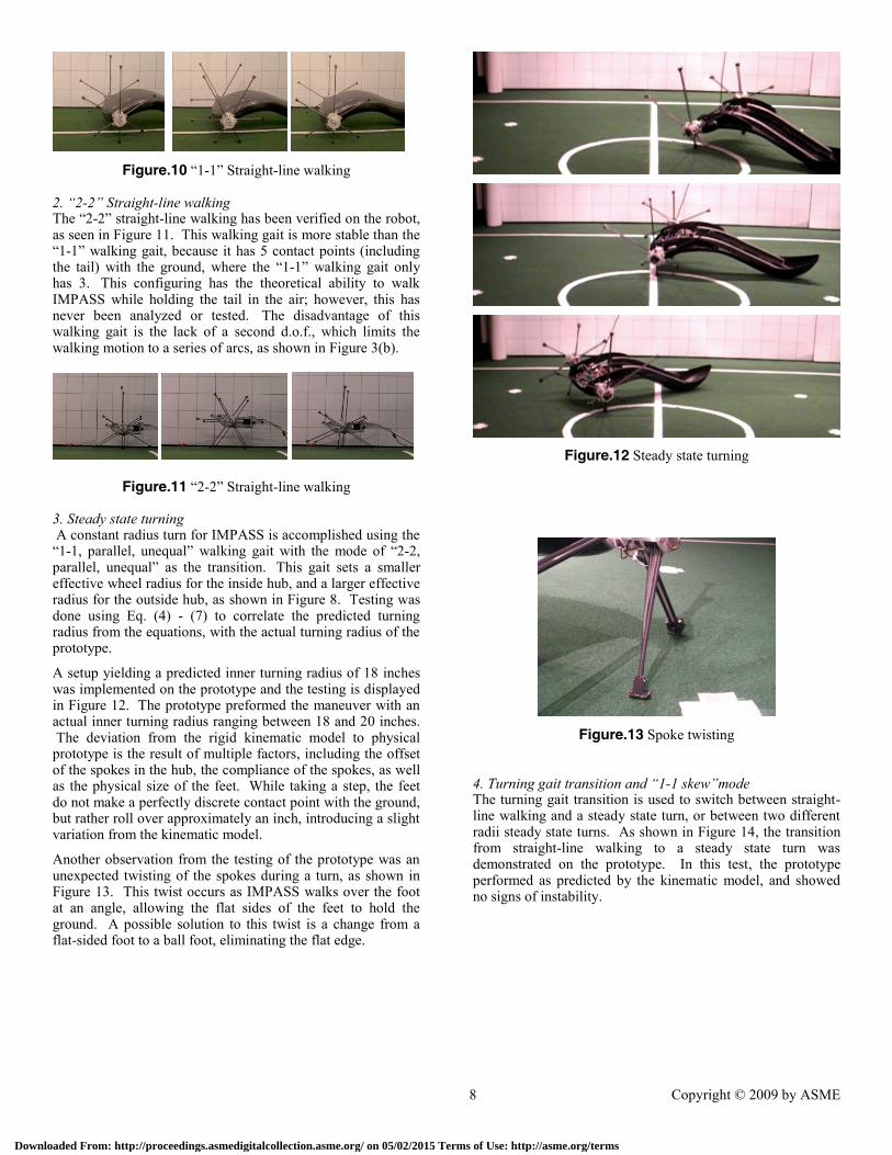
Figure.11 “2-2” Straight-line walking 3. Steady state turning A constant radius turn for IMPASS is accomplished using the “1-1, parallel, unequal” walking gait with the mode of “2-2, parallel, unequal” as the transition. This gait sets a smaller effective wheel radius for the inside hub, and a larger effective radius for the outside hub, as shown in Figure 8. Testing was done using Eq. (4) - (7) to correlate the predicted turning radius from the equations, with the actual turning radius of the prototype.
A setup yielding a predicted inner turning radius of 18 inches was implemented on the prototype and the testing is displayed in Figure 12. The prototype preformed the maneuver with an actual inner turning radius ranging between 18 and 20 inches. The deviation from the rigid kinematic model to physical prototype is the result of multiple factors, including the offset of the spokes in the hub, the compliance of the spokes, as well as the physical size of the feet. While taking a step, the feet do not make a perfectly discrete contact point with the ground, but rather roll over approximately an inch, introducing a slight variation from the kinematic model.
Another observation from the testing of the prototype was an unexpected twisting of the spokes during a turn, as shown in Figure 13. This twist occurs as IMPASS walks over the foot at an angle, allowing the flat sides of the feet to hold the ground. A possible solution to this twist is a change from a flat-sided foot to a ball foot, eliminating the flat edge.
Figure.12 Steady state turning
Figure.13 Spoke twisting
4. Turning gait transition and “1-1 skew”mode The turning gait transition is used to switch between straight-line walking and a steady state turn, or between two different radii steady state turns. As shown in Figure 14, the transition from straight-line walking to a steady state turn was demonstrated on the prototype. In this test, the prototype performed as predicted by the kinematic model, and showed no signs of instability.
Downloaded From: http://proceedings.asmedigitalcollection.asme.org/ on 05/02/2015 Terms of Use: http://asme.org/terms

9 Copyright © 2009 by ASME
Figure.14 Steady state turning
The turning gait transition takes advantage of the “1-1 skew” mode of IMPASS. The “1-1 skew” mode allows the prototype to change the roll orientation of the body. While there is slight flex in the spokes during this motion, the prototype of IMPASS remains stable and controllable over this range of motion. 5. Joystick control The IMPASS prototype is also able to be controlled through the use of a joystick connected to the laptop. This joystick allows simple commands to be input into the IMPASS software, including forward and reverse moving velocities, the desired turning radius of the robot, and the nominal walking height.
While performing tests with the joystick control, an interesting divergence from the rigid kinematic model was observed. The rigid kinematic model shows only an instantaneous d.o.f in the contact mode of "1-1, parallel, equal”, meaning that the robot cannot change the roll angle of the body without taking a step forward using the “1-1 skew” mode as the intermediate phase. However, the prototype proved that this transformation directly from one roll angle to another is possible without any other movement due to the compliance in the spokes. Without walking forward, leaning the prototype to the side causes the spokes to bend slightly, allowing this theoretically instantaneous d.o.f to be continuous in certain range on the physical prototype. Actually, the feature of compliant spokes makes the robot more flexible for steering.
7. CONCLUSION AND FUTURE WORK The spoke wheel robot presented in this paper is treated through the viewpoint of mechanisms with variable topologies, given the fact that it is able to actively change its kinematic configurations with respect to the ground. It is concluded all types of steering motions of the robot can be uniformly interpreted as series of configuration transformations. Previous kinematic models are modified in order to maintain the coherence of the body and base coordinate frames in different configurations. The design of the prototype is demonstrated. Based on this prototype, the characteristic motions of the robot are verified with experiments.
As for future work, motion planning based on configuration transformation will be intensively studied, with the objective to track any path given. The prototype development mainly includes the touch sensor at the spoke feet, the computer cart inside the body shell, software architecture and so on.
ACKNOWLEDGE The support of the National Science Foundation under Grant No. 0535012 is gratefully acknowledged. The authors would
also like to thank Shawn Kimmel and his senior design project team for their contribution in the development of IMPASS prototypes.
REFERENCE [1] Saranli, U., Buehler, M., and Koditschek, D.E. “RHex: A
Simple and Highly Mobile Hexapod Robot,” International Journal of Robotics Research 20, July 2001, pp. 616-631.
[2] Quinn, R.D., Nelson, G.M., Ritzmann, R.E., Bachmann, R.J., Kingsley, D.A., Offi, J.T. and Allen, T.J. (2003), "Parallel Strategies For Implementing Biological Principles Into Mobile Robots," International Journal of Robotics Research, Vol. 22 (3) pp. 169-186.
[3] Laney, D. and Hong, D.W.,”Kinematic Analysis of a Novel Rimless Wheel with Independently Actuated Spokes”, 29th ASME Mechanisms and Robotics Conference, Long Beach, California, September 24-28, 2005.
[4] Hong. D.W. and Laney, D., “Preliminary Design and Kinematic Analysis of a Mobility Platform with Two Actuated Spoke Wheels”, US-Korea Conference on Science, Technology and Entrepreneurship (UKC 2006), Mechanical Engineering & Robotics Symposium, Teaneck, New Jersey, August 10-13, 2006.
[5] Laney, D. and Hong, D.W., “Three-Dimensional Kinematic Analysis of the Actuated Spoke Wheel Robot”. 30th ASME Mechanisms and Robotics Conference, Philadelphia, Pennsylvania, September 10-13, 2006.
[6] Wang, Y., Ren, P., Hong, D., “Mobility and Geometrical Analysis of a Two Actuated Spoke Wheel Robot Modeled as a Mechanism with Variable Topology,” 32nd ASME Mechanisms and Robotics Conference, Brooklyn, New York, August 3-6, 2008,
[7] Huang, Z., Ge, Q.J., “A Simple Method for Mobility Analysis Using Reciprocal Screws”, 30th ASME Mechanisms and Robotics Conference, Philadelphia, Pennsylvania, September 10-13, 2006.
[8] Dai, J.S., Huang, Z., Lipkin, H., “Mobility of Overconstrained Parallel Mechanisms,” Journal of Mechanical Design, Vol.128, January 2006
[9] Kuo, C.H., Yan, H.S., “On the Mobility and Configuration Singularity of Mechanisms with Variable Topologies,” Journal of Mechanical Design, Vol. 129, June 2007
[10] J. P. Merlet, “Singular configurations of parallel manipulators and Grassmann geometry,” International Journal of Robotics Research,Vol.8,no.5,pp.45–56,1989
[11] Ren, P., Wang, Y., Hong, D., “Three-dimensional Kinematic Analysis of a Two Actuated Spoke Wheel Robot Based on its Equivalency to A Serial Manipulator,” 32nd ASME Mechanisms and Robotics Conference, Brooklyn, New York, August 3-6, 2008
Downloaded From: http://proceedings.asmedigitalcollection.asme.org/ on 05/02/2015 Terms of Use: http://asme.org/terms