
Kidde ADS - ttlcompany.comttlcompany.com/documentation/download.php?fname=./1.KIDDE_FE… · Kidde...
10
A UTC Fire & Security Company Effective: April 2007 K-90-120 Kidde ADS 3-Way Directional Ball Valve P/Ns: 90-118325-00X and 90-118327-00X FEATURES • For Use with Kidde ADS Systems • Cost-Effective Option for Protecting Multiple Hazards • Pneumatic Operation Using Nitrogen Pilot Cylinder • 3-Way Valve Comes Pre-Assembled with Pneumatic Actuator and Solenoid • Stainless Steel • Low Loss Three Port Design • FM Approved DESCRIPTION The Kidde ADS Series System offers the use of direc- tional valves for protection of multiple hazards from one central storage bank of agent and nitrogen driver cylin- ders. When the same set of cylinders are used to protect different hazards, 3-Way Directional Ball Valves may be included in the system. Since only one system (i.e., distri- bution piping and nozzles) can be entered and calculated at one time, it is necessary to create separate projects (.flc files) for each configuration. With respect to the directional valves, separate objects are used for a given valve size depending on the orientation of the valve. An “open” valve is used to allow agent to flow through the side (branch) outlet of the valve, and a “closed” valve would be used to allow agent to flow through the run out- let of the valve. When working with multiple files, the user should ensure that the type, diameter and length of any pipes common to more than one project file are identical. The pipe locking feature is useful here. In addition, the agent quantity per cylinder and area of the nitrogen restrictor orifice should be identical. Note: Per NFPA 2001–In sections where a valve arrangement introduces sections of closed pip- ing, such sections shall be equipped with pres- sure relief devices, or the valves shall be designed to prevent entrapment of liquid. For pressure relief of manifold arrangements using directional valves, use a safety outlet (P/N 844346). Figure 1. T Flow Ball Position Figure 2. L Flow Ball Position TOP VIEW PIPING TO HAZARD AGENT SOURCE PIPING TO HAZARD TOP VIEW AGENT SOURCE
Transcript of Kidde ADS - ttlcompany.comttlcompany.com/documentation/download.php?fname=./1.KIDDE_FE… · Kidde...

A UTC Fire & Security Company
Effective: April 2007K-90-120
Kidde ADS3-Way Directional Ball ValveP/Ns: 90-118325-00X and 90-118327-00X
FEATURES• For Use with Kidde ADS Systems• Cost-Effective Option for Protecting
Multiple Hazards• Pneumatic Operation Using Nitrogen
Pilot Cylinder
• 3-Way Valve Comes Pre-Assembled with Pneumatic Actuator and Solenoid
• Stainless Steel• Low Loss Three Port Design• FM Approved
DESCRIPTIONThe Kidde ADS Series System offers the use of direc-tional valves for protection of multiple hazards from onecentral storage bank of agent and nitrogen driver cylin-ders. When the same set of cylinders are used to protectdifferent hazards, 3-Way Directional Ball Valves may beincluded in the system. Since only one system (i.e., distri-bution piping and nozzles) can be entered and calculatedat one time, it is necessary to create separate projects(.flc files) for each configuration. With respect to thedirectional valves, separate objects are used for a givenvalve size depending on the orientation of the valve. An“open” valve is used to allow agent to flow through theside (branch) outlet of the valve, and a “closed” valvewould be used to allow agent to flow through the run out-let of the valve. When working with multiple files, the usershould ensure that the type, diameter and length of anypipes common to more than one project file are identical.The pipe locking feature is useful here. In addition, theagent quantity per cylinder and area of the nitrogenrestrictor orifice should be identical.
Note: Per NFPA 2001–In sections where a valvearrangement introduces sections of closed pip-ing, such sections shall be equipped with pres-sure relief devices, or the valves shall bedesigned to prevent entrapment of liquid. Forpressure relief of manifold arrangements usingdirectional valves, use a safety outlet (P/N844346).
Figure 1. T Flow Ball Position Figure 2. L Flow Ball PositionTOP VIEW
PIPING TO HAZARD
AGENTSOURCE
PIPING TO HAZARD
TOP VIEW
AGENTSOURCE

3-W
ay
Ba
llV
alv
e
Sw
ing
Ch
ec
ko
rC
he
ck
Va
lve
Ele
ctr
icC
on
tro
lH
ea
dE
EE
E
Dis
ch
arg
eM
an
ifo
ld
CY
L.1
-3
3-W
ay
Ba
llV
ALV
E1
3-W
ay
Ba
llV
ALV
E2
PIP
ING
TO
HA
ZA
RD
BH
AZ
AR
DA
CY
L2
-3
PIP
ING
TO
#3
N2
FM
-200
Tan
k
#2
N2
FM
-200
Tan
k
#1
N2
FM
-200
Tan
k
Sw
ing
Ch
ec
ko
rC
he
ck
Va
vle
Fle
xH
os
eo
rH
ard
Pip
e
Ele
ctr
icC
on
tro
l
1/4
inc
hS
ch
40
pip
eo
r
Sta
inle
ss
ste
el
tub
ing
5/1
6O
.D.
X0
.03
5"
wa
ll
He
ad
He
ad
Ele
ctr
icC
on
tro
lN
itro
ge
nP
ilo
t
Nit
rog
en
Pil
ot
Pan
el
E
•N
itro
gen
pilo
tlin
eco
nn
ecte
dto
each
3-w
ay
ball
valv
e.
•E
lectr
icco
ntr
olh
ead
so
neach
nit
rog
en
pilo
tcylin
der
toco
ntr
ol
the
dir
ecti
on
alvalv
es.
•E
ach
pilo
tcylin
der
co
uld
als
ob
em
an
ually
actu
ate
d.
Ch
an
ne
lsN
ee
de
d=
#o
fD
ire
cti
on
al
Va
lve
s
EE
Pla
inN
ut–
Dis
ch
arg
eH
ead
(Typ
.),P
/N872450
Pla
inN
ut–
Dis
ch
arg
eH
ead
(Typ
.),P
/N872450
1"
Tra
ns
fer
Ho
se
(Ty
p.)
P/N
06
-11
82
07
-00
3
Ele
ctr
icC
on
tro
lH
ead
Actu
ati
on
Assem
bly
Kit
for
225
an
d395
lb.S
yste
ms,
P/N
06-1
29882-0
01
for
675
an
d1010
lb.S
yste
ms,
P/N
06-1
29985-0
01
So
l.S
ol.
SID
EV
IEW
TO
PV
IEW
Op
tio
na
l
No
te:
Tw
o3-w
ay
ball
valv
es
are
sh
ow
nfo
rre
fere
nce.
Gen
era
lu
sag
eis
no
tlim
ited
totw
o3-w
ay
valv
es.
Pre
ss
ure
Re
gu
lato
r(P
/N0
6-1
18
33
4-0
01
)F
ac
tory
Se
tto
11
6P
SI
(8b
ar)
•A
llcylin
ders
mu
st
be
of
the
sam
esiz
ean
dfi
lld
en
sit
y.
•A
lln
itro
gen
dri
vers
mu
st
be
of
the
sam
esiz
ean
dp
ressu
re(1
800
PS
IG).
No
te:
Th
earr
an
gem
en
tssh
ow
nab
ove
use
the
larg
er
cylin
ders
(675
an
d1010
lb.)
for
the
pu
rpo
se
of
cla
rity
.T
his
co
ncep
tcan
als
ob
each
ieved
usin
gth
e225
an
d395
lb.cylin
ders
.
SO
LE
lec
tric
So
len
oid
(P/N
06
-11
83
29
-00
1)
S/O
Sa
fety
Ou
tle
t(P
/N8
44
34
6)
S/O
Figu
re 3
. A
rran
gem
ent 1
: 3-W
ay B
all V
alve
with
Pne
umat
ic A
ctua
tor D
edic
ated
for E
ach
Dire
ctio
nal V
alve
- 2 -

3-W
ay
Ball
Va
lve
Sw
ing
Ch
eck
or
Ch
eck
Va
lve
Ele
ctr
icC
on
tro
lH
ead
E
EE
E
Dis
ch
arg
eM
an
ifo
ld
CY
L.1
-3
3-W
ay
Ba
llV
ALV
E1
3-W
ay
Ba
llV
ALV
E2
PIP
ING
TO
HA
ZA
RD
BH
AZ
AR
DA
CY
L2
-3
PIP
ING
TO
#3
N2
FM
-200
Tan
k
#2
N2
#1
N2
Sw
ing
Ch
ec
ko
rC
he
ck
Va
lve
Fle
xH
os
eo
rH
ard
Pip
e
Ele
ctr
icC
on
tro
lH
ead
1/4
"S
ch
40
Pip
eo
r
Sta
inle
ss
ste
el
tub
ing
5/1
6O
.D.
X0
.03
5"
wa
llN
itro
gen
Pilo
t
Pan
el
•N
itro
ge
np
ilo
tli
ne
co
nn
ec
ted
toe
ac
h3
-wa
yb
all
va
lve
.
•E
lec
tric
co
ntr
ol
he
ad
an
do
ne
pil
ot
cy
lin
de
rfe
ed
sa
llth
eb
all
va
lve
s.
•E
ac
h3
-wa
yb
all
va
lve
isw
ith
as
ole
no
idp
ne
um
ati
ca
ctu
ato
r(r
ota
tes
90
°).
So
l.S
ol.
Ch
an
nels
Need
ed
=#
of
Dir
ecti
on
alV
alv
es
+1
1"
Tra
ns
fer
Ho
se
(Ty
p.)
,P
/N0
6-1
18
20
7-0
03
E
Ele
ctr
icC
on
tro
lH
ea
dP
lain
Nu
t–D
isc
ha
rge
He
ad
(Ty
p.)
P/N
87
24
50
Pla
inN
ut–
Dis
ch
arg
eH
ea
d(T
yp
.),
P/N
87
24
50
EE
SID
EV
IEW
TO
PV
IEW
FM
-200
Tan
kF
M-2
00
Tan
k
No
te:
Tw
o3
-wa
yb
all
va
lve
sa
res
ho
wn
for
refe
ren
ce
.G
en
era
lu
sa
ge
isn
ot
lim
ite
dto
two
3-w
ay
va
lve
s.
•A
llc
yli
nd
ers
mu
st
be
of
the
sa
me
siz
ea
nd
fill
de
ns
ity.
•A
lln
itro
ge
nd
riv
ers
mu
st
be
of
the
sa
me
siz
ea
nd
pre
ss
ure
(18
00
PS
IG).
Pre
ssu
reR
eg
ula
tor
(P/N
06-1
18334-0
01)
Facto
ryS
et
to116
PS
I(8
bar)
SO
LE
lectr
icS
ole
no
id(P
/N06-1
18329-0
01)
Ac
tua
tio
nA
ss
em
bly
Kit
for
22
5a
nd
39
5lb
.S
ys
tem
s,
P/N
06
-12
98
82
-00
1fo
r6
75
an
d1
01
0lb
.S
ys
tem
s,
P/N
06
-12
99
85
-00
1
No
te:
Th
ea
rra
ng
em
en
tss
ho
wn
ab
ov
eu
se
the
larg
er
cy
lin
de
rs(6
75
an
d1
01
0lb
.)fo
rth
ep
urp
os
eo
fc
lari
ty.
Th
isc
on
ce
pt
ca
na
lso
be
ac
hie
ve
du
sin
gth
e2
25
an
d3
95
lb.
cy
lin
de
rs.
S/O
Sa
fety
Ou
tle
t(P
/N8
44
34
6)
S/O
Figu
re 4
. A
rran
gem
ent 2
: 3-W
ay B
all V
alve
with
Pne
umat
ic A
ctua
tor C
ontro
lled
by a
24
Vdc
Sol
enoi
d
- 3 -
OPERATION
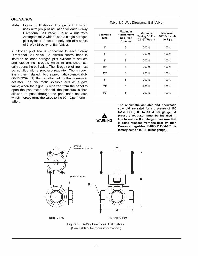
Figure 5. 3-Way Directional Ball Valves (See Table 2 for more information.)
FRONT VIEWSIDE VIEW
c
B
A
SPRINGRETURN ACTUATOR
BALL VALVE
Note: Figure 3 illustrates Arrangement 1 whichuses nitrogen pilot actuation for each 3-WayDirectional Ball Valve. Figure 4 illustratesArrangement 2 which uses a single nitrogenpilot cylinder to actuate only one of a seriesof 3-Way Directional Ball Valves
A nitrogen pilot line is connected to each 3-WayDirectional Ball Valve. An electric control head isinstalled on each nitrogen pilot cylinder to actuateand release the nitrogen, which, in turn, pneumati-cally opens the ball valve. The nitrogen pilot line mustbe installed with a pressure regulator. The nitrogenline is then installed into the pneumatic solenoid (P/N06-118329-001) that is attached to the pneumaticactuator. The pneumatic solenoid acts as a gatevalve; when the signal is received from the panel toopen the pneumatic solenoid, the pressure is thenallowed to pass through the pneumatic actuator,which thereby turns the valve to the 90° “Open” orien-tation.
Ball ValveSize
MaximumNumber from
One PilotCylinder
MaximumTubing 5/16" x0.035" Weight
Maximum1/4" Schedule
40 Pipe
4" 3 200 ft. 100 ft.
3" 3 200 ft. 100 ft.
2" 8 200 ft. 100 ft.
1½" 8 200 ft. 100 ft.
1¼" 8 200 ft. 100 ft.
1" 8 200 ft. 100 ft.
3/4" 8 200 ft. 100 ft.
1/2" 8 200 ft. 100 ft.
Table 1. 3-Way Directional Ball Valve
WARNING
The pneumatic actuator and pneumaticsolenoid are rated for a pressure of 100to150 PSI (6.89 to 10.34 bar gauge). Apressure regulator must be installed inline to reduce the nitrogen pressure thatis being released from the pilot cylinder.Pressure regulator P/N06-118334-001 isfactory set to 116 PSI (8 bar gauge).
- 4 -

Part Number Nominal Size Material Body Style Inlets PortT-Flow
EquivalentLength
L-FlowEquivalent
Length
90-118325-001 1/2" 316 SS Threaded NPT Full 0.42 ft. 3.67 ft.
90-118325-002 3/4" 316 SS Threaded NPT Full 0.50 ft. 5.42 ft.
90-118325-003 1" 316 SS Threaded NPT Full 0.94 ft. 7.38 ft.
90-118325-004 1¼" 316 SS Threaded NPT Full 1.07 ft. 11.18 ft.
90-118327-001 1½" 316 SS Bolted NPT Full 2.39 ft. 14.05 ft.
90-118327-002 2" 316 SS Bolted NPT Full 2.73 ft. 17.80 ft.
90-118327-003 3" 316 SS Bolted NPT Full 3.02 ft. 24.56 ft.
90-118327-004 4" 316 SS Bolted Flanged Full 4.54 ft. 25.62 ft.
Part Number Nominal SizeDimensions Valve Working
PressureBreakaway
TorqueA* B C*
90-118325-001 1/2" 6 in. 0.59 8 in. 500 PSIG 100 in.-lb.
90-118325-002 3/4" 6 in. 0.79 8 in. 500 PSIG 130 in.-lb.
90-118325-003 1" 7 in. 0.98 10 in. 500 PSIG 190 in.-lb.
90-118325-004 1¼" 7 in. 1.25 10 in. 500 PSIG 300 in.-lb.
90-118327-001 1½" 9 in. 1.50 12 in. 500 PSIG 576 in.-lb.
90-118327-002 2" 15 in. 1.97 14 in. 500 PSIG 877 in.-lb.
90-118327-003 3" 22 in. 2.93 23 in. 500 PSIG 2366 in.-lb.
90-118327-004 4" 23 in. 3.53 23 in. 500 PSIG 3300 in.-lb.
*Note: Dimensions are approximate for the entire assembly.
Part Number NominalSize
ActuatorMechanism Actuator Type Actuator
VolumeActuatorTorque
WorkingPressure
MaximumPressure
90-118325-001 1/2" Rack and Pinion Spring Return 14 cu. in. 180 in.-lb. 115 PSIG 145 PSIG
90-118325-002 3/4" Rack and Pinion Spring Return 14 cu. in. 180 in.-lb. 115 PSIG 145 PSIG
90-118325-003 1" Rack and Pinion Spring Return 21 cu. in. 266 in.-lb. 115 PSIG 145 PSIG
90-118325-004 1¼" Rack and Pinion Spring Return 40 cu. in. 429 in.-lb. 115 PSIG 145 PSIG
90-118327-001 1½" Rack and Pinion Spring Return 61 cu. in. 782 in.-lb. 115 PSIG 145 PSIG
90-118327-002 2" Rack and Pinion Spring Return 92 cu. in. 924 in.-lb. 115 PSIG 145 PSIG
90-118327-003 3" Rack and Pinion Spring Return 366 cu. in. 3539 in.-lb. 115 PSIG 145 PSIG
90-118327-004 4" Rack and Pinion Spring Return 366 cu. in. 3539 in.-lb. 115 PSIG 145 PSIG
Table 2. 3-Way Directional Ball Valve Specifications
Table 2. 3-Way Directional Ball Valve Specifications (cont.)
Table 3. Pneumatic Actuator Specifications
- 5 -
COMPONENTS3-WAY DIRECTIONAL BALL VALVES(P/NS 90-118325-00X AND 90-118327-00X)The stainless steel, 3-Way Directional Ball Valves areused for applications where a single bank of cylinders areused to protect multiple hazards (see ADS Design, Instal-lation, Operation and Maintenance Manual, P/N 90-FM200M-030, for more information). The directionalvalves have a factory installed pneumatic, spring loadedactuator and range in sizes from 1/2 inch to 4 inches. Thedirectional valves can be installed in the network, pro-vided that they are accounted for in the software calcula-tion. Refer to Figure 5, and Table 2 for more information.
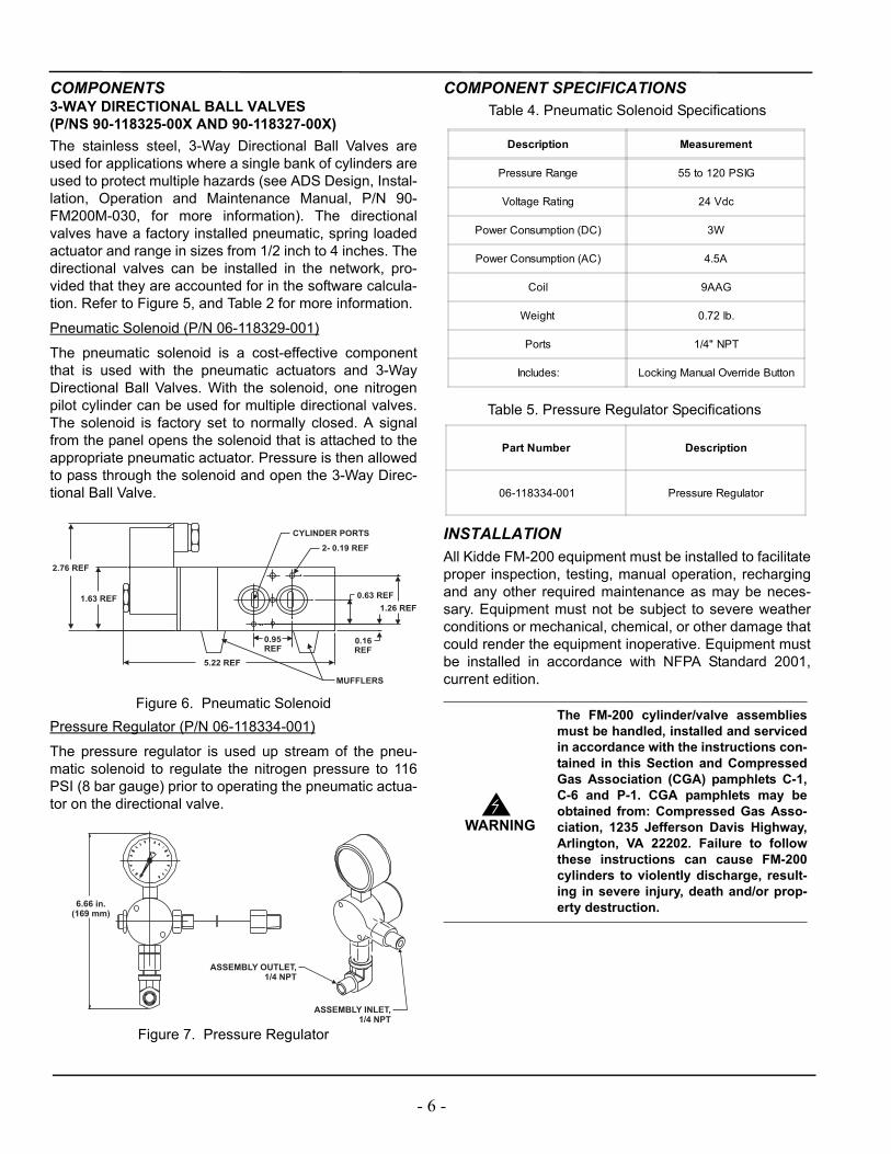
Pneumatic Solenoid (P/N 06-118329-001)
The pneumatic solenoid is a cost-effective componentthat is used with the pneumatic actuators and 3-WayDirectional Ball Valves. With the solenoid, one nitrogenpilot cylinder can be used for multiple directional valves.The solenoid is factory set to normally closed. A signalfrom the panel opens the solenoid that is attached to theappropriate pneumatic actuator. Pressure is then allowedto pass through the solenoid and open the 3-Way Direc-tional Ball Valve.
Figure 6. Pneumatic SolenoidPressure Regulator (P/N 06-118334-001)
The pressure regulator is used up stream of the pneu-matic solenoid to regulate the nitrogen pressure to 116PSI (8 bar gauge) prior to operating the pneumatic actua-tor on the directional valve.
Figure 7. Pressure Regulator
COMPONENT SPECIFICATIONS
INSTALLATIONAll Kidde FM-200 equipment must be installed to facilitateproper inspection, testing, manual operation, rechargingand any other required maintenance as may be neces-sary. Equipment must not be subject to severe weatherconditions or mechanical, chemical, or other damage thatcould render the equipment inoperative. Equipment mustbe installed in accordance with NFPA Standard 2001,current edition.
0.95REF
5.22 REF
2.76 REF
1.63 REF 0.63 REF
0.16REF
1.26 REF
CYLINDER PORTS
2- 0.19 REF
MUFFLERS
6.66 in.(169 mm)
ASSEMBLY INLET,1/4 NPT
ASSEMBLY OUTLET,1/4 NPT
WARNING
The FM-200 cylinder/valve assembliesmust be handled, installed and servicedin accordance with the instructions con-tained in this Section and CompressedGas Association (CGA) pamphlets C-1,C-6 and P-1. CGA pamphlets may beobtained from: Compressed Gas Asso-ciation, 1235 Jefferson Davis Highway,Arlington, VA 22202. Failure to followthese instructions can cause FM-200cylinders to violently discharge, result-ing in severe injury, death and/or prop-erty destruction.
Description Measurement
Pressure Range 55 to 120 PSIG
Voltage Rating 24 Vdc
Power Consumption (DC) 3W
Power Consumption (AC) 4.5A
Coil 9AAG
Weight 0.72 lb.
Ports 1/4" NPT
Includes: Locking Manual Override Button
Part Number Description
06-118334-001 Pressure Regulator
Table 4. Pneumatic Solenoid Specifications
Table 5. Pressure Regulator Specifications
- 6 -

PRESSURE ACTUATION PIPEThe pressure actuation pipe must be 1/4-inch Schedule40 or 80 pipe or 5/16 in. O.D. x 0.035 in. wall stainlesssteel tubing. Actuation lines shall be protected againstcrimping and mechanical damage (per NFPA 2001, Sec-tion 2-3.4.2). The pipe or tubing must be routed in themost direct manner with a minimum number of fittings.Pipe and fittings must be in accordance with the require-ments listed in the ADS Design, Installation, Operationand Maintenance Manual (P/N 90-FM200M-030). Fittingscan be flared or compression type. The pressure-temper-ature ratings of the fitting manufacturer must not beexceeded.
DIRECTIONAL VALVES WITH PNEUMATICACTUATORS AND SOLENOIDS
Note: Flanged fittings are to be installed per ANSI B16.5.
1. Gather the required parts for the chosen directionalsystem based upon the number of 3-Way Direc-tional Ball Valves needed and the actuation schemedesired.
• Single pilot cylinder actuation requires one pilotcylinder, actuation hoses (number of hosesequals two times the number of directionalvalves), electric control head, the directionalvalves with solenoid pneumatic actuators and apressure regulator.
• Multiple pilot actuation requires pilot cylinders(number of pilot cylinders equals one times thenumber of directional valves), actuation hoses(number of hoses equals one times the numberof directional valves), electric control heads(number of control heads equals one times thenumber of directional valves), directional valveswith pneumatic actuators and a pressure regula-tor.
Note: The pressure regulator must be located within 12 in. of the solenoid and pneumatic actuator.
2. Ensure that all directional valves are in the “straightthrough” position before installation (the T-port in thevalve should be open on both ends with the sideport closed).
Figure 8. Straight Through OrientationThe directional valve must be installed so that the 90°turn of the actuator brings the T-port open on the sidebranch and the end of the valve that faces the FM-200source. The arrow on the valve must be pointed in thedirection of the flow.
Figure 9. 90° Orientation3. Connect the actuators on the directional valves to
the pneumatic source in one of two ways:For pilot cylinder actuation, all directional valvesmust have a 24 Vdc solenoid (P/N 06-118329-001)and a 24 Vdc connection from the control panel.
✶ Connect the pilot cylinder to the second pressur-ization port of the solenoid actuator using theactuation line.
✶ Connect each of the solenoids and the electriccontrol head to the control panel so that the elec-tric control head fires and the correct directionalvalve operates for the desired hazard.
✶ Test each hazard with the control panel by listen-ing for the solenoid click at each directionalvalve.
✶ Reconnect all electrical connections.✶ Attach an electric control head to the pilot cylin-
der (being sure it is set before installation).
VALVE 1
3-Way Ball
HAZARD APIPING TO
VALVE 2
3-Way Ball
PIPING TOHAZARD B
Straight through position;Closed to pipe network.
Nipple
Cap Endof Manifold
VALVE 1
3-Way Ball
HAZARD APIPING TO
VALVE 2
3-Way Ball
PIPING TOHAZARD B
90° counterclockwiseturn to Hazard B.
(In Alarm)
Nipple
Cap Endof Manifold
- 7 -

4. Set the control panel to provide a 5.5 second delaybetween the firing of the pilot cylinders for the direc-tional valves and the firing of the FM-200 system(see Table 6). This delay provides sufficient time forthe valves to fully open before the system is dis-charged.
Note: 5.5 seconds is the maximum time needed for the 4 in. ball valve to open under pressure.
SYSTEM RELEASECONTROL CONFIGURATIONIMPORTANT— The information in this paragraph refersto circuits and wiring employed on PEGAsys panels;specific ADS configurations and/or other programmablepanels may require different wiring and/or panel-to-panelconnections.A maximum of eight suppression hazards and a maxi-mum of eight electrically actuated nitrogen driver cylin-ders are allowed per system. Multiple panels may beemployed to control and release the system. The small-est ADS system configuration would require a minimumof four release circuits.
Figure 10. Typical Single Panel System Release Circuit Wiring (See Notes below.)
Figure 11. Typical Multiple Panel System Release Circuit Wiring (See Notes below.)
Notes:1. Must use Pneumatic Solenoid (P/N 06-118329-001).
Ratings: 24 Vdc, 4.8 W; 2.0 Vdc minimum dropout.2. Must use 24 Volt DC control head. The fire alarm
suppression panel release circuit must be capable of supplying a minimum of 24 Vdc @ 2.8 Amps for 30 milliseconds for control head P/N 890181, and a minimum of 24 Vdc @ 0.5 Amps continuous for con-trol head P/N 81-100000-001.
3. Release control relays are only required if the nitro-gen driver solenoids are released by a separate panel. Relays employed must be electrically com-patible with the release circuit output characteristics for both pull-in and dropout voltages.
WARNING
Regardless of configuration, the follow-ing sequence of activation must beadhered to:1. When a call for suppression is
received by the panel for a specificsuppression zone, the appropriateselector valve solenoid and nitrogenpilot control head must activate within0.5 seconds of each other.
2. Six to ten seconds after the selectorvalve solenoid and nitrogen pilot con-trol head actuates, the appropriatenitrogen driver control heads mustactivate. After any hazard activates,no other activation is allowed until thesystem is serviced. Failure to followthese sequence could result in sys-tem malfunction.
Part Number Description Time DelaysRequired to Open
90-118325-001 1/2" NPT 5.5 sec.
90-118325-002 3/4" NPT 5.5 sec.
90-118325-003 1" NPT 5.5 sec.
90-118325-004 1¼" NPT 5.5 sec.
90-118327-001 1½" NPT 5.5 sec.
90-118327-002 2" NPT 5.5 sec.
90-118327-003 3" NPT 5.5 sec.
90-118327-004 4" Flanged 5.5 sec.
PEGAsys or otherFM Approved/UL Listedfire alarm suppression
control panel
ReleaseCircuit
ReleaseCircuit
ReleaseCircuit
Selector ValveSolenoid (see note 1)
Nitrogen PilotControl Head (see note 2)
Nitrogen DriverControl Head (see note 2)
PEGAsys or otherprogrammable FM Approved(for FM insured installations)/UL Listed compatible fire alarmsuppression control panel
S
S
S
S Denotes Supervised Circuit
ReleaseCircuit
Selector ValveSolenoid (see note 1)
S
Nitrogen DriverControl Head (see note 2)
SRelease
Circuit
Circuit
PEGAsys or otherFM Approved/UL Listedfire alarm suppressioncontrol panel
ReleaseCircuit
ReleaseCircuit
ReleaseCircuit
Selector ValveSolenoid (see note 1)
Nitrogen PilotControl Head (see note 2)
ReleaseControl Relay (see note 3)
Circuit
PEGAsys or otherFM Approved/UL Listedfire alarm suppression
control panel
InitiatingCircuit
ReleaseCircuit
ReleaseCircuit
Nitrogen DriverControl Head (see Note 2)
Nitrogen DriverControl Head (see Note 2)
EOLR
+_
S Denotes Supervised Circuit
S
S
S
S
S
S
Panel 1
Panel 2
Selector ValveSolenoid (see note 1)
S
CircuitRelease
PEGAsys or otherprogrammable FM Approved
(for FM insured installations)/UL Listed compatible fire alarm
suppression control panel
PEGAsys or otherprogrammable FM Approved
(for FM insured installations)/UL Listed compatible fire alarm
suppression control panel
Table 6. Directional Valve Data
- 8 -

4. A means of manual release of the system shall be provided. Manual release shall be accomplished by a mechanical manual release, or by an electrical manual release, when the control equipment moni-tors the battery voltage level of the standby battery supply and will provide a low battery signal. The release shall cause simultaneous operation of auto-matically operated valves controlling agent release and distribution.
✶ Refer to the PEGAsys Installation, Operation and Maintenance Manual (P/N 76-200016-001) for com-plete details.
ORDERING INFORMATION
WARNING
The referenced control heads andsolenoids are compatible with PEGA-sys panels. The use of other panels tooperate these control heads and sole-noids has not been verified and couldresult in system malfunction.
- 9 -

Part Number Description
Valves
90-118325-001 3-Way Directional Valve, 1/2-inch
90-118325-002 3-Way Directional Valve, 3/4-inch
90-118325-003 3-Way Directional Valve, 1-inch
90-118325-004 3-Way Directional Valve, 1¼-inch
90-118327-001 3-Way Directional Valve, 1½-inch
90-118327-002 3-Way Directional Valve, 2-inch
90-118327-003 3-Way Directional Valve, 3-inch
90-118327-004 3-Way Directional Valve, 4-inch
Pneumatic Solenoid(Note: Part of Valve Assembly. Use below for spare parts only.)
06-118329-001 Pneumatic Solenoid, 24 Vdc
Pressure Regulator
06-118334-001 Pressure Regulator, 116 PSI (8 bar)
A UTC Fire & Security Company400 Main StreetAshland, MA 01721Ph: 508.881.2000Fax: 508.881.8920www.kiddefiresystems.com
This literature is provided for informational purposes only. KIDDE-FENWAL, INC. assumes no responsibility for the product’s suitability for a particular application. The product must be properly applied to work correctly.If you need more information on this product, or if you have a particular problem or ques-tion, contact KIDDE-FENWAL, INC., Ashland, MA 01721. Telephone: (508) 881-2000.
K-90-120 Rev AB © 2007 Kidde-Fenwal Inc. Printed in USA


