KHAIRUL ANWAR B MOHD YAKOP
24
AUTOMATIC PET FEEDER WITH CLIENT/SERVER APPLICATION KHAIRUL ANWAR B MOHD YAKOP UNIVERSITI MALAYSIA PAHANG
Transcript of KHAIRUL ANWAR B MOHD YAKOP
AUTOMATIC PET FEEDER WITH CLIENT/SERVER APPLICATION
KHAIRUL ANWAR B MOHD YAKOP
UNIVERSITI MALAYSIA PAHANG
AUTOMATIC PET FEEDER WITH CLIENT/SERVER APPLICATION
KHAIRUL ANWAR B MOHD YAKOP
A thesis submitted in fulfilment of the
requirements for the award of the degree of
Electrical Engineering (Electronics)
Faculty of Electical & Electronics Engineering
Universiti Malaysia Pahang
November,2007
“All the trademark and copyrights use herein are property of their respective owner.
References of information from other sources are quoted accordingly; otherwise the
information presented in this report is solely work of the author.”
Signature : ____________________________
Author : KHAIRUL ANWAR B. MOHD YAKOP
Date : 10 NOVEMBER 2008
“I hereby acknowledge that the scope and quality of this thesis is qualified for the award of the
Bachelor Degree of Electrical Engineering (Electronics)”
Signature : ______________________________________________
Name : NURULFADZILAH BT HASAN
Date : 10 NOVEMBER 2008

To my beloved father, Mohd Yakop B. Abd Hamid and mother, Siti Mariam Bt. Ismail
Who always pray for me and give me courage to finish this thesis.
And also to those people who have guided and inspired me throughout my journey.
Thank you for the supports and advices that have been given.
ACKNOWLEDGEMENT
This project would not have been possible without considerable guidance and
support. So, I would like to acknowledge those who have enabled me to complete
this project.
Firstly, I would like to thank my project supervisor, Mrs Nurulfadzilah binti
Hasan, for providing the guideline with continues advices and feedback
throughout the duration of finishing this project.
Secondly, I would also like to thank all University Malaysia Pahang staff
members that I may have called upon for assistance since the genesis of this
project. Their opinions and suggestions have helped me in realizing this project.
Also not to be forgotten, I would like to thank for all my friends with the support,
valuable help and sharing ideas during the progress of this project.
Finally, I would like to thank my family for their understanding, encouragement
and support, towards the completion of my project. Thank you so much.
ABSTRACT
This project explains about designing and developing an automatic pet feeder
that comes with the client/server application. Not like the ordinary pet feeding
product in the market today that requires the user to set the times of feeding, this
automatic pet feeder use the ultrasonic sensor that placed in front of the device to
sense the presence of the pet. The purpose and concept of this project is the same
with other device like it, to feed the pet without the present of the owner. This
project was developed using Motorola MC68HC11A1P microcontroller that play
the role as the main controller system. The microcontroller used in this project is
programmed using assembly language. The microcontroller controls the rotation
of the motor and send signal to the server computer to update the database at the
server. The server and client application for this project is developed using
Visual Basic 6.0 software. Finally, this project allows the user to view the
information about the feeding from other computer where internet becomes the
medium of interaction.
ABSTRAK
Projek ini menerangkan tentang langkah mereka dan membangunkan sebuah
pemberi makanan binatang peliharaan automatik yang datang bersama applikasi
pelangan/pelayan. Tidak seperti pemberi makanan binatang peliharaan
automatik yang berada di pasaran hari ini yang memerlukan penguna untuk
menetapkan masa pemberian makanan, pemberi makanan automatik ini
menggunakan pengesan ultrasonik di hadapannya untuk mengesan kehadiran
binatang peliharaan. Tujuan dan konsep projek ini adalah sama seperti alat lain
sepertinya iaitu memberi makanan kepada binatang peliharaan tanpa kehadiran
pemilik. Projek ini dibangunkan menggunakan pengawal mikro Motorolla
MC68HC11A1P yang memainkan peranan sebagai pengawal utama keseluruhan
system. Pengawal mikro yang digunakan dalam projek ini diprogram
menggunakan bahasa pengaturcara. Pengawal mikro yang digunakan mengawal
pusingan motor dan menghantar isyarat kepada komputer pelayan untuk
mengemaskini data didalamnya. Applikasi pelangan dan pelayan untuk projek ini
dibangunkan menggunakan perisian Visual Basic 6.0. Akhirnya, projek ini
membenarkan pengguna untuk mendapatkan informasi tentang proses pemberian
makanan menggunakan komputer lain dimana internet menjadi medium untuk
berinteraksi.
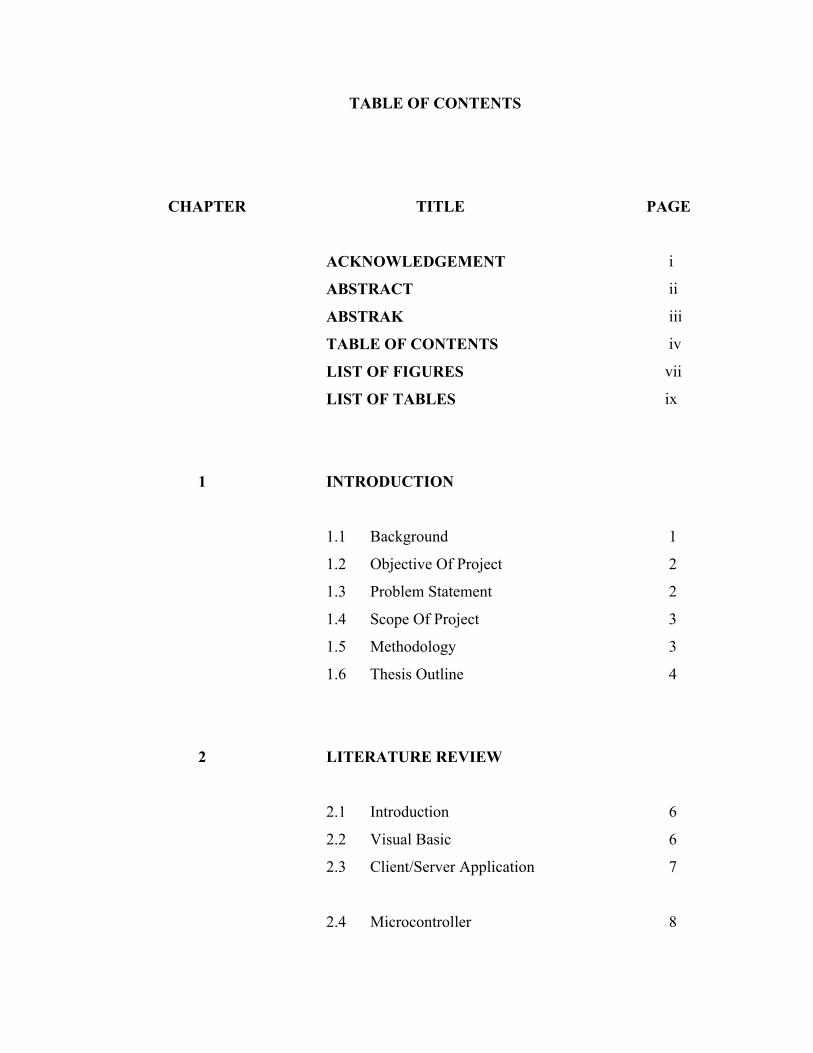
TABLE OF CONTENTS
CHAPTER TITLE PAGE
ACKNOWLEDGEMENT i
ABSTRACT ii
ABSTRAK iii
TABLE OF CONTENTS iv
LIST OF FIGURES vii
LIST OF TABLES ix
1 INTRODUCTION
1.1 Background 1
1.2 Objective Of Project 2
1.3 Problem Statement 2
1.4 Scope Of Project 3
1.5 Methodology 3
1.6 Thesis Outline 4
2 LITERATURE REVIEW
2.1 Introduction 6
2.2 Visual Basic 6
2.3 Client/Server Application 7
2.4 Microcontroller 8
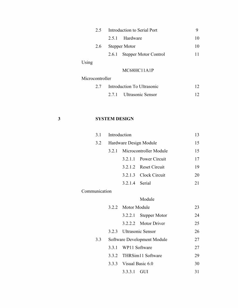
2.5 Introduction to Serial Port 9
2.5.1 Hardware 10
2.6 Stepper Motor 10
2.6.1 Stepper Motor Control
Using
MC68HC11A1P
Microcontroller
11
2.7 Introduction To Ultrasonic 12
2.7.1 Ultrasonic Sensor 12
3 SYSTEM DESIGN
3.1 Introduction 13
3.2 Hardware Design Module 15
3.2.1 Microcontroller Module 15
3.2.1.1 Power Circuit 17
3.2.1.2 Reset Circuit 19
3.2.1.3 Clock Circuit 20
3.2.1.4 Serial
Communication
Module
21
3.2.2 Motor Module 23
3.2.2.1 Stepper Motor 24
3.2.2.2 Motor Driver 25
3.2.3 Ultrasonic Sensor 26
3.3 Software Development Module 27
3.3.1 WP11 Software 27
3.3.2 THRSim11 Software 29
3.3.3 Visual Basic 6.0 30
3.3.3.1 GUI 31
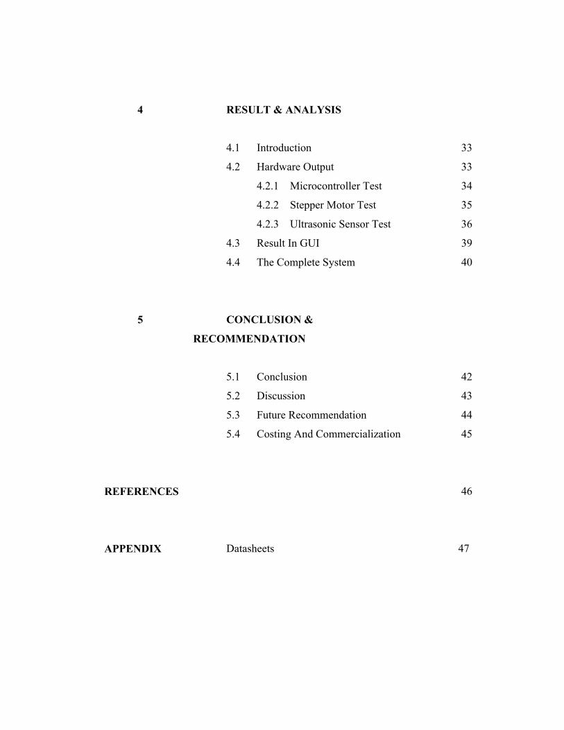
4 RESULT & ANALYSIS
4.1 Introduction 33
4.2 Hardware Output 33
4.2.1 Microcontroller Test 34
4.2.2 Stepper Motor Test 35
4.2.3 Ultrasonic Sensor Test 36
4.3 Result In GUI 39
4.4 The Complete System 40
5 CONCLUSION &
RECOMMENDATION
5.1 Conclusion 42
5.2 Discussion 43
5.3 Future Recommendation 44
5.4 Costing And Commercialization 45
REFERENCES 46
APPENDIX Datasheets 47
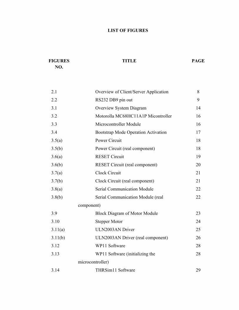
LIST OF FIGURES
FIGURES NO.
TITLE PAGE
2.1 Overview of Client/Server Application 8
2.2 RS232 DB9 pin out 9
3.1 Overview System Diagram 14
3.2 Motorolla MC68HC11A1P Micontroller 16
3.3 Microcontroller Module 16
3.4 Bootstrap Mode Operation Activation 17
3.5(a) Power Circuit 18
3.5(b) Power Circuit (real component) 18
3.6(a) RESET Circuit 19
3.6(b) RESET Circuit (real component) 20
3.7(a) Clock Circuit 21
3.7(b) Clock Circuit (real component) 21
3.8(a) Serial Communication Module 22
3.8(b) Serial Communication Module (real
component)
22
3.9 Block Diagram of Motor Module 23
3.10 Stepper Motor 24
3.11(a) ULN2003AN Driver 25
3.11(b) ULN2003AN Driver (real component) 26
3.12 WP11 Software 28
3.13 WP11 Software (initializing the
microcontroller)
28
3.14 THRSim11 Software 29
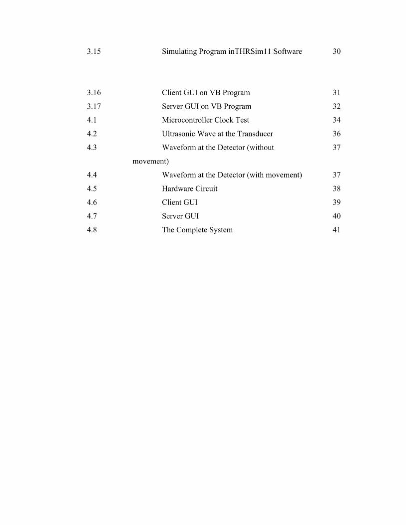
3.15 Simulating Program inTHRSim11 Software 30
3.16 Client GUI on VB Program 31
3.17 Server GUI on VB Program 32
4.1 Microcontroller Clock Test 34
4.2 Ultrasonic Wave at the Transducer 36
4.3 Waveform at the Detector (without
movement)
37
4.4 Waveform at the Detector (with movement) 37
4.5 Hardware Circuit 38
4.6 Client GUI 39
4.7 Server GUI 40
4.8 The Complete System 41
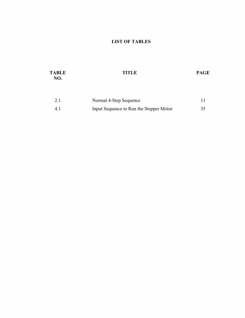
LIST OF TABLES
TABLE NO.
TITLE PAGE
2.1 Normal 4-Step Sequence 11
4.1 Input Sequence to Run the Stepper Motor 35
CHAPTER 1
INTRODUCTION
1.1 Background
Pet care should be fun, not burdensome and so the goal of this project is to assist
owner with pet care by providing an automatic pet feeder. The purpose of the
project helps the owner of the pet feeding their pet on time even when they are
not at home. Other than that, it also can help the owner know the diet of their pet.
Knowing the diet of the pet is very important for the owner to make sure that the
pet is in good health.
This system assist pet owner to feed the pet. The system act in two ways, one is
feeding the pet and sends the feeding information to owner. After it feed the pet,
the system will stop responding for certain time in order to make sure that the pet
do not eat too much.
1.2 Objective of Project
The objectives of this project are:-
i. To create a device that can automatically feed pets without the present
of the owner by developing a microcontroller based system that
response to the ultrasonic sensor, connected to a PC (server).
ii. To develop a client/server application using Visual Basic.
1.3 Problem Statement
It is common to know that pet care is a burden to the pet owner. Any pet need to
be taken care and the owner need to be there to take care of them. Some pet
cannot control their diet and will eat as long as there’s food for them. Other pet
will just eat a certain type of food. In other word, the owner cannot leave the pet
on its own.
The problem occurs when the owner has to leave their pet for certain time and
there’s no one there to watch them. Therefore to solve the problem, system that
can automatically feed the pet without the presence of the owner is needed to
make sure that the pet stay healthy.
1.4 Scope of Project
The system is built using:
i. MC68HC11A1P microcontroller
ii. The Permanent Magnet Stepper Motor as the output from the
controller.
iii. Visual Basic 6.0 as the main software development program.
iv. Ultrasonic sensor as the input of the system.
1.5 Methodology
Step taken to archive the objectives of this project are:
Studies on the hardware that needed for this project such as controller,
motor, ultrasonic sensor and others.
Do studies on the compatible software that available and related to the
project in order to perform certain tasks like developed GUI, used internet
services and others.
Designing the hardware of the project such as microcontroller circuit and
ultrasonic sensor based on the literature review that has been done.
Do simulation for the program that will be burn into the microcontroller
to make sure that the program work as wanted.
Designing the client/server application using the software that has been
decided.
Communication test between the hardware and the software used in this
project to make sure it operates as a system.
Integrate the software and hardware to complete the project.
Collect result get from the test and simulation that has been done.
Analysis the data in order to make sure that the system work perfectly.
1.6 Thesis Outline
This thesis contains five chapters. Chapter 1 is about the introduction of the
project which consists of background, problem statement, scopes, methodology,
objectives of the project and also the thesis outline.
Chapter 2 provides a literature review on sending data using client/server
application in general and discusses about controlling motor using
microcontroller and how it can be integrated with the server as the control panel.
This chapter is based on the journal and other reference that has been use to
complete this project.
Chapter 3 discusses all about the design system of the project. This
chapter includes step by step explanation on implementing ideas onto the
hardware that has been chosen. Then creating the graphical user interfaces (GUI)
for PC server and PC client until all of the components combined together
as one perfect system.
Chapter 4 will be the outcomes or result from the project which consists of figure
of the hardware project, table of simulation result and other related stuff. The
discussion focused on the result is base on the experiment.
Finally, chapter 5 explains the summary of the project where it concludes overall
of the project, obstacle faces and some recommendations for future development.
CHAPTER 2
LITEATURE REVIEW
2.1 Introduction
In completing this project, some literature review has been done on
several resources. The theories and descriptions have been taken as guidance in
completing this project. This chapter will present and give an overview about
some application that use client/server application, the use of ultrasonic motion
detector and other related project that use microcontroller as the main controller.
2.2 Visual Basic
Visual Basic (VB) is the third-generation event-driven programming
language and integrated development environment (IDE) from Microsoft for its
COM programming model. VB is also considered a relatively easy to learn and
use programming language, because of its graphical development features and
BASIC. [Wikipedia, 2008]. It is easier to do the programming using Visual Basic
because it is an Object Oriented Programming.
A specific button can be program using the Visual Basic application. The
position of the buttons and other components can be adjusted without using a
coding. Visual Basic program display a Windows style screen (called a form)
with a boxes into which users type (and edit) information and buttons that they
click to initiates action. The buttons and boxes are referred to as control. Forms
and control are called objects.[D.I Schneider, 1999].
2.3 Client/Server Application
A client/server application is a piece of software that runs in client
computer and make request to a remote server. Many such application are
written in high level visual programming language where the user interface,
forms and most business logic reside in the client application. Often the server
act as the database and the client is a program that requesting data or info.
Client/server describes the relationship between two computer
programs in which one program, the client, makes a service request from
another program, the server.[Wikipedia, 2008]. In order to develop this unit,
knowledge in some of software programming such as Visual Basic are
required.
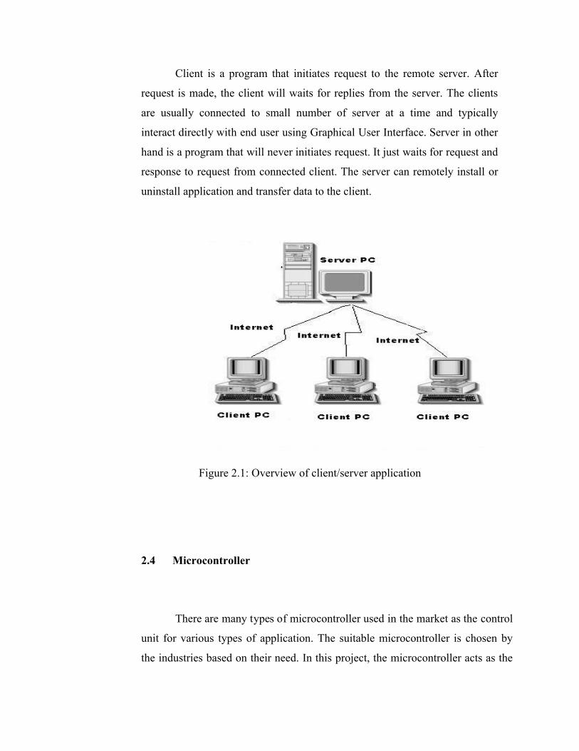
Client is a program that initiates request to the remote server. After
request is made, the client will waits for replies from the server. The clients
are usually connected to small number of server at a time and typically
interact directly with end user using Graphical User Interface. Server in other
hand is a program that will never initiates request. It just waits for request and
response to request from connected client. The server can remotely install or
uninstall application and transfer data to the client.
Figure 2.1: Overview of client/server application
2.4 Microcontroller
There are many types of microcontroller used in the market as the control
unit for various types of application. The suitable microcontroller is chosen by
the industries based on their need. In this project, the microcontroller acts as the
brain of the system because it controls all the action made by the system. In this
project, 6811 microcontroller is used.
Microcontrollers store their programs and data in memory. Memory is
organized as a contiguous string of addresses, or locations. Each memory
location contains eight bits of data. The entire amount of memory that a
processor can access is called its address space. [Motorola Incorporation, 1996].
The 6811 has an address space of 65,536 memory locations, corresponding
exactly to 16 bits of address information. This mean that a 16-bit numeral can be
used to point at, or address, any of the memory bytes in the address space of the
6811.
2.5 Introduction to Serial Port
Two standards of interface between PCs and other devices are
parallel and serial port communications. Parallel port communication sends data
at the same time while serial communication port sends data in a serial fashion.
Communication between HC11 board and the PC is through serial port for the
reason that the HC11 board already has existing serial communication IC chips.
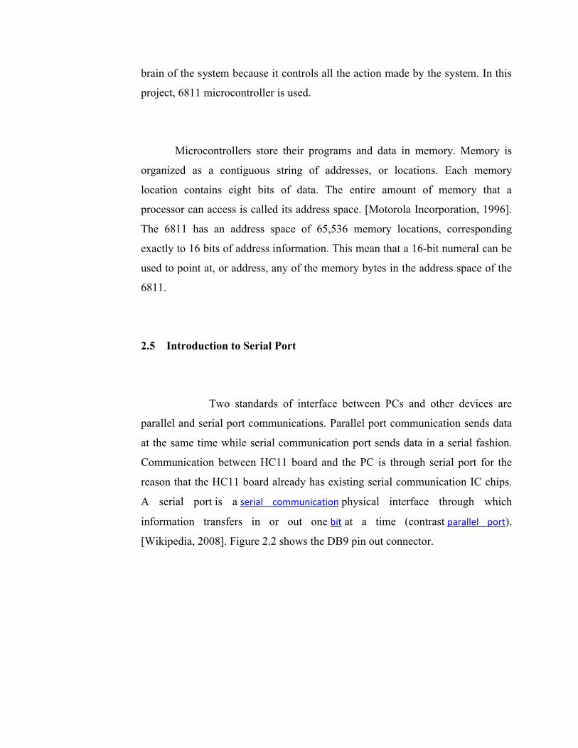
A serial port is a serial communication physical interface through which
information transfers in or out one bit at a time (contrast parallel port).
[Wikipedia, 2008]. Figure 2.2 shows the DB9 pin out connector.
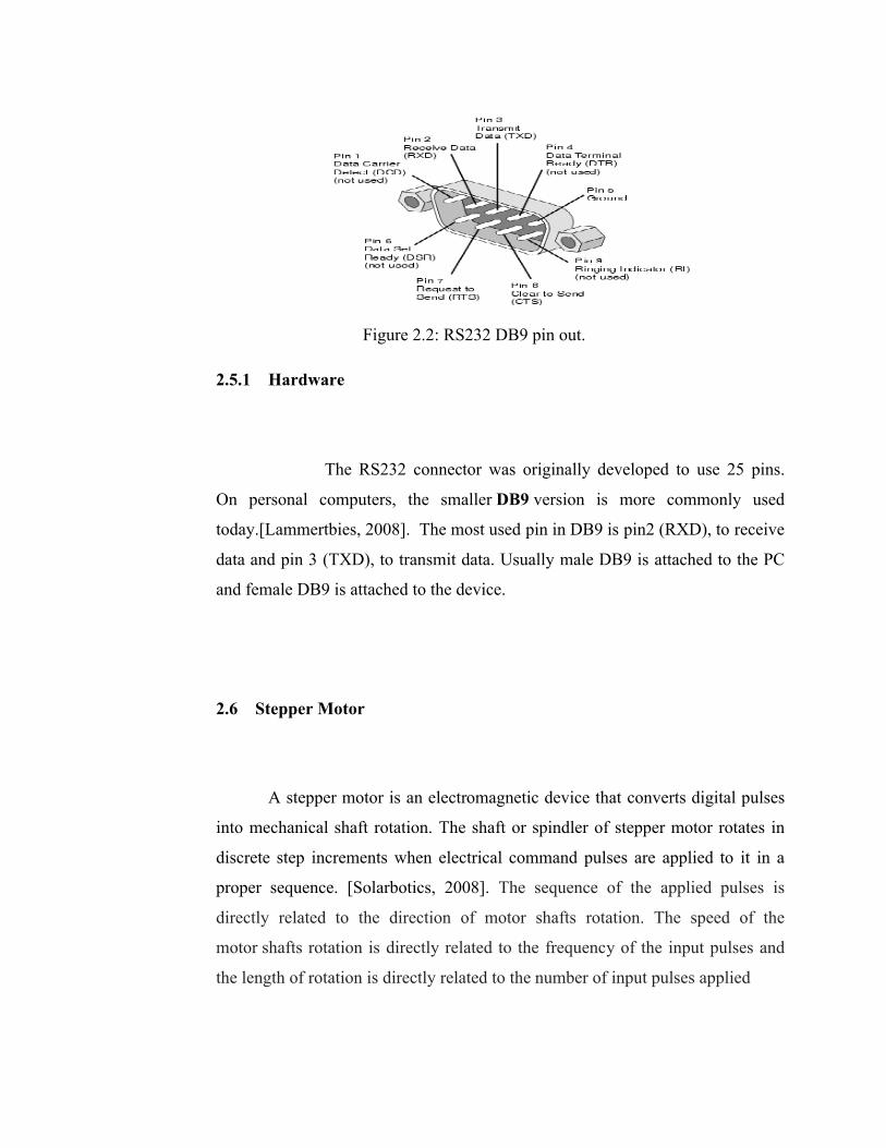
Figure 2.2: RS232 DB9 pin out.
2.5.1 Hardware
The RS232 connector was originally developed to use 25 pins.
On personal computers, the smaller DB9 version is more commonly used
today.[Lammertbies, 2008]. The most used pin in DB9 is pin2 (RXD), to receive
data and pin 3 (TXD), to transmit data. Usually male DB9 is attached to the PC
and female DB9 is attached to the device.
2.6 Stepper Motor
A stepper motor is an electromagnetic device that converts digital pulses
into mechanical shaft rotation. The shaft or spindler of stepper motor rotates in
discrete step increments when electrical command pulses are applied to it in a
proper sequence. [Solarbotics, 2008]. The sequence of the applied pulses is
directly related to the direction of motor shafts rotation. The speed of the
motor shafts rotation is directly related to the frequency of the input pulses and
the length of rotation is directly related to the number of input pulses applied