Keysight 53150A/151A/152A Microwave Frequency...
115
Keysight 53150A/151A/152A Microwave Frequency Counter This guide describes how to use the Keysight 53150A, 53151A, and 53152A Microwave Frequency Counters. The information in this guide applies to instruments having the number prefix listed below, unless accompanied by a “Manual Updating Changes” package indicating otherwise. SERIAL PREFIX NUMBER: 3735A, US3925, and US4050 (53150A) 3736A, US3926, and US4051 (53151A) 3737A, US3927, and US4052 (53152A) Assembly Level Service Guide
Transcript of Keysight 53150A/151A/152A Microwave Frequency...

Keysight 53150A/151A/152A Microwave Frequency Counter
This guide describes how to use the Keysight 53150A, 53151A, and 53152A Microwave Frequency Counters. The information in this guide applies to instruments having the number prefix listed below, unless accompanied by a “Manual Updating Changes” package indicating otherwise.
SERIAL PREFIX NUMBER: 3735A, US3925, and US4050 (53150A)3736A, US3926, and US4051 (53151A)3737A, US3927, and US4052 (53152A)
Assembly Level Service Guide

2 Keysight 53150A/151A/152A Assembly Level Service Guide
NoticesCopyright Notice© Keysight Technologies 1999 - 2017No part of this manual may be repro-duced in any form or by any means (including electronic storage and retrieval or translation into a foreign language) without prior agreement and written consent from Keysight Technol-ogies as governed by United States and international copyright laws.
Manual Part Number53150-90015
EditionEdition 3, December 1, 2017
Printed in:Printed in Malaysia
Published by:Keysight TechnologiesBayan Lepas Free Industrial Zone,11900 Penang, Malaysia
Technology Licenses The hardware and/or software described in this document are fur-nished under a license and may be used or copied only in accordance with the terms of such license.
Declaration of ConformityDeclarations of Conformity for this product and for other Keysight prod-ucts may be downloaded from the Web. Go to http://www.keysight.com/go/conformity. You can then search by product number to find the latest Dec-laration of Conformity.
U.S. Government RightsThe Software is “commercial computer software,” as defined by Federal Acqui-sition Regulation (“FAR”) 2.101. Pursu-ant to FAR 12.212 and 27.405-3 and Department of Defense FAR Supple-ment (“DFARS”) 227.7202, the U.S. government acquires commercial com-puter software under the same terms by which the software is customarily provided to the public. Accordingly, Keysight provides the Software to U.S. government customers under its stan-dard commercial license, which is embodied in its End User License Agreement (EULA), a copy of which can be found at http://www.keysight.com/find/sweula. The license set forth in the EULA represents the exclusive authority by which the U.S. government may use, modify, distribute, or disclose the Soft-ware. The EULA and the license set forth therein, does not require or per-mit, among other things, that Keysight: (1) Furnish technical information related to commercial computer soft-ware or commercial computer software documentation that is not customarily provided to the public; or (2) Relinquish to, or otherwise provide, the govern-ment rights in excess of these rights customarily provided to the public to use, modify, reproduce, release, per-form, display, or disclose commercial computer software or commercial com-puter software documentation. No additional government requirements beyond those set forth in the EULA shall apply, except to the extent that those terms, rights, or licenses are explicitly required from all providers of commercial computer software pursu-ant to the FAR and the DFARS and are set forth specifically in writing else-where in the EULA. Keysight shall be under no obligation to update, revise or otherwise modify the Software. With respect to any technical data as defined by FAR 2.101, pursuant to FAR 12.211 and 27.404.2 and DFARS 227.7102, the U.S. government acquires no greater than Limited Rights as defined in FAR 27.401 or DFAR 227.7103-5 (c), as applicable in any technical data.
WarrantyTHE MATERIAL CONTAINED IN THIS DOCUMENT IS PROVIDED “AS IS,” AND IS SUBJECT TO BEING CHANGED, WITHOUT NOTICE, IN FUTURE EDITIONS. FURTHER, TO THE MAXIMUM EXTENT PERMITTED BY APPLICABLE LAW, KEYSIGHT DIS-CLAIMS ALL WARRANTIES, EITHER EXPRESS OR IMPLIED, WITH REGARD TO THIS MANUAL AND ANY INFORMA-TION CONTAINED HEREIN, INCLUD-ING BUT NOT LIMITED TO THE IMPLIED WARRANTIES OF MER-CHANTABILITY AND FITNESS FOR A PARTICULAR PURPOSE. KEYSIGHT SHALL NOT BE LIABLE FOR ERRORS OR FOR INCIDENTAL OR CONSE-QUENTIAL DAMAGES IN CONNECTION WITH THE FURNISHING, USE, OR PERFORMANCE OF THIS DOCUMENT OR OF ANY INFORMATION CON-TAINED HEREIN. SHOULD KEYSIGHT AND THE USER HAVE A SEPARATE WRITTEN AGREEMENT WITH WAR-RANTY TERMS COVERING THE MATE-RIAL IN THIS DOCUMENT THAT CONFLICT WITH THESE TERMS, THE WARRANTY TERMS IN THE SEPARATE AGREEMENT SHALL CONTROL.
Safety Information
CAUTIONA CAUTION notice denotes a hazard. It calls attention to an operating proce-dure, practice, or the like that, if not correctly performed or adhered to, could result in damage to the product or loss of important data. Do not pro-ceed beyond a CAUTION notice until the indicated conditions are fully understood and met.
WARNINGA WARNING notice denotes a hazard. It calls attention to an operating proce-dure, practice, or the like that, if not correctly performed or adhered to, could result in personal injury or death. Do not proceed beyond a WARNING notice until the indicated conditions are fully understood and met.

Safety Symbols
The following symbols on the instrument and in the documentation indicate precautions which must be taken to maintain safe operation of the instrument.
Caution, risk of danger (refer to this manual for specific Warning or Caution information)
Caution, risk of electric shock
Earth (ground) terminal Frame or chassis (ground) terminal
Alternating current (AC) Direct current (DC)
Keysight 53150A/151A/152A Assembly Level Service Guide 3

Detailed Warranty Information
Keysight does not warrant that the operation of Keysight products will be uninterrupted or error free. If Keysight is unable, within a reasonable time, to repair or replace any product to a condition as warranted, customer will be entitled to a refund of the purchase price upon prompt return of the product.
Keysight products may contain remanufactured parts equivalent to new in performance or may have been subjected to incidental use.
The warranty period begins on the date of delivery or on the date of installation if installed by Keysight. If customer schedules or delays Keysight installation more than 30 days after delivery, warranty begins on the 31st day from delivery.
Warranty does not apply to defects resulting from (a) improper or inadequate maintenance or calibration, (b) software, interfacing, parts or supplies not supplied by Keysight, (c) unauthorized modification or misuse, (d) operation outside of the published environmental specifications for the product, or (e) improper site preparation or maintenance.
TO THE EXTENT ALLOWED BY LOCAL LAW, THE ABOVE WARRANTIES ARE EXCLUSIVE AND NO OTHER WARRANTY OR CONDITION, WHETHER WRITTEN OR ORAL, IS EXPRESSED OR IMPLIED AND KEYSIGHT SPECIFICALLY DISCLAIMS ANY IMPLIED WARRANTIES OR CONDITIONS OF MERCHANTABILITY, SATISFACTORY QUALITY, AND FITNESS FOR A PARTICULAR PURPOSE.
Keysight will be liable for damage to tangible property per incident up to the greater of $300,000 or the actual amount paid for the product that is the subject of the claim, and for damages for bodily injury or death, to the extent that all such damages are determined by a court of competent jurisdiction to have been directly caused by a defective Keysight product.
TO THE EXTENT ALLOWED BY LOCAL LAW, THE REMEDIES IN THIS WARRANTY STATEMENT ARE CUSTOMER’S SOLE AND EXCLUSIVE REMEDIES. EXCEPT AS INDICATED ABOVE, IN NO EVENT WILL KEYSIGHT OR ITS SUPPLIERS BE LIABLE FOR LOSS OF DATA OR FOR DIRECT, SPECIAL, INCIDENTAL, CONSEQUENTIAL (INCLUDING LOST PROFIT OR DATA), OR OTHER DAMAGE, WHETHER BASED IN CONTRACT, TORT, OR OTHERWISE.
For consumer transactions in Australia and New Zealand: the warranty terms contained in this statement, except to the extent lawfully permitted, do not exclude, restrict or modify and are in addition to the mandatory statutory rights applicable to the sale of this product to you.
4 Keysight 53150A/151A/152A Assembly Level Service Guide
Safety Considerations
Read the information below before using this instrument.
The following general safety precautions must be observed during all phases of operation, service, and repair of this instrument. Failure to comply with these precautions or with specific warnings elsewhere in this manual violates safety standards for design, manufacture, and intended use of the instrument. Keysight Technologies assumes no liability for the customer’s failure to comply with these requirements.
Whenever it is likely that the protection has been impaired, the instrument must be made inoperative and be secured against any unintended operation.
If this instrument is to be energized via an autotransformer (for voltage reduction), make sure the common terminal is connected to the earthed pole terminal (neutral) of the power source.
Instructions for adjustments while covers are removed and for servicing are for use by trained personnel only. To avoid dangerous electric shock, do not perform such adjustments or servicing unless qualified to do so.
For continued protection against fire, replace the line fuse(s) with fuses of the same current rating and type (for example, normal blow, time delay). Do not use repaired fuses or short-circuited fuseholders.
WARNINGINSTRUCTIONS FOR ADJUSTMENTS WHILE COVERS ARE REMOVED AND FOR SERVICING ARE FOR USE BY SERVICE-TRAINED PERSONNEL ONLY. TO AVOID DANGEROUS ELECTRIC SHOCK, DO NOT PERFORM SUCH ADJUSTMENTS OR SERVICING UNLESS QUALIFIED TO DO SO.
WARNINGANY INTERRUPTION OF THE PROTECTIVE GROUNDING CONDUCTOR (INSIDE OR OUTSIDE THE PRODUCT’S CIRCUITRY) OR DISCONNECTING THE PROTECTIVE EARTH TERMINAL WILL CAUSE A POTENTIAL SHOCK HAZARD THAT COULD RESULT IN PERSONAL INJURY. (GROUNDING ONE CONDUCTOR OF A TWO CONDUCTOR OUTLET IS NOT SUFFICIENT PROTECTION.)
Keysight 53150A/151A/152A Assembly Level Service Guide 5

Safety Earth Ground
An uninterruptible safety earth ground must be maintained from the mains power source to the product’s ground circuitry.
Acoustic Noise Emissions
LpA<47 dB at operator position, at normal operation, tested per EN 27779. All data are the results from type test.
Geräuschemission
LpA<47 dB am Arbeits platz, normaler Betrieb, geprüft nach EN 27779. Die Angagen beruhen auf Ergebnissen von Typenprüfungen.
Electrostatic Discharge Immunity Testing
When the product is tested with 8kV AD, 4kV CD and 4kV ID according to IEC801-2, a system error may occur that may affect measurement data made during these disturbances. After these occurrences, the system self-recovers without user intervention.
WARNINGWHEN MEASURING POWER LINE SIGNALS, BE EXTREMELY CAREFUL AND ALWAYS USE A STEP-DOWN ISOLATION TRANSFORMER WHICH OUTPUT IS COMPATIBLE WITH THE INPUT MEASUREMENT CAPABILITIES OF THIS PRODUCT. THIS PRODUCT’S FRONT AND REAR PANELS ARE TYPCIALLY AT EARTH GROUND. THUS, NEVER TRY TO MEASURE AC POWER LINE SIGNALS WITHOUT AN ISOLATION TRANSFORMER.
6 Keysight 53150A/151A/152A Assembly Level Service Guide

Waste Electrical and Electronic Equipment (WEEE) Directive
This instrument complies with the WEEE Directive marking requirement. This affixed product label indicates that you must not discard this electrical or electronic product in domestic household waste.
Product category:
With reference to the equipment types in the WEEE directive Annex 1, this instrument is classified as a “Monitoring and Control Instrument” product.
The affixed product label is as shown below.
Do not dispose in domestic household waste.
To return this unwanted instrument, contact your nearest Keysight Service Center, or visit http://about.keysight.com/en/companyinfo/environment/takeback.shtml for more information.
Sales and Technical Support
To contact Keysight for sales and technical support, refer to the support links on the following Keysight websites:
– www.keysight.com/find/53150A (product-specific information and support, software and documentation updates)
– www.keysight.com/find/assist(worldwide contact information for repair and service)
Keysight 53150A/151A/152A Assembly Level Service Guide 7

THIS PAGE HAS BEEN INTENTIONALLY LEFT BLANK.
8 Keysight 53150A/151A/152A Assembly Level Service Guide

Table of Contents
Safety Symbols . . . . . . . . . . . . . . . . . . . . . . . . . . . . . . . . . . . . . . . . . . . . .3Detailed Warranty Information . . . . . . . . . . . . . . . . . . . . . . . . . . . . . . . . .4Safety Considerations . . . . . . . . . . . . . . . . . . . . . . . . . . . . . . . . . . . . . . . .5Safety Earth Ground . . . . . . . . . . . . . . . . . . . . . . . . . . . . . . . . . . . . . . . . .6Acoustic Noise Emissions . . . . . . . . . . . . . . . . . . . . . . . . . . . . . . . . . . . . .6Geräuschemission . . . . . . . . . . . . . . . . . . . . . . . . . . . . . . . . . . . . . . . . . . .6Electrostatic Discharge Immunity Testing . . . . . . . . . . . . . . . . . . . . . . . .6Waste Electrical and Electronic Equipment (WEEE) Directive . . . . . . . .7
Product category: . . . . . . . . . . . . . . . . . . . . . . . . . . . . . . . . . . . . . . . .7Sales and Technical Support . . . . . . . . . . . . . . . . . . . . . . . . . . . . . . . . . .7List of Figures . . . . . . . . . . . . . . . . . . . . . . . . . . . . . . . . . . . . . . . . . . . . .13List of Tables . . . . . . . . . . . . . . . . . . . . . . . . . . . . . . . . . . . . . . . . . . . . . .15
In This Guide
How to Use This Guide . . . . . . . . . . . . . . . . . . . . . . . . . . . . . . . . . . . . . .18Repair Strategy . . . . . . . . . . . . . . . . . . . . . . . . . . . . . . . . . . . . . . . . .18Instrument Identification . . . . . . . . . . . . . . . . . . . . . . . . . . . . . . . . . .19Instruments Covered by this Guide . . . . . . . . . . . . . . . . . . . . . . . . . .19Assembly-Level Service Guide Organization . . . . . . . . . . . . . . . . . .19How to Order Guides . . . . . . . . . . . . . . . . . . . . . . . . . . . . . . . . . . . . .20
Description of the Microwave Frequency Counter . . . . . . . . . . . . . . . .21Options . . . . . . . . . . . . . . . . . . . . . . . . . . . . . . . . . . . . . . . . . . . . . . . . . .22
Hardware . . . . . . . . . . . . . . . . . . . . . . . . . . . . . . . . . . . . . . . . . . . . . .22Support . . . . . . . . . . . . . . . . . . . . . . . . . . . . . . . . . . . . . . . . . . . . . . .22
Accessories Supplied and Available . . . . . . . . . . . . . . . . . . . . . . . . . . . .23Accessories Supplied . . . . . . . . . . . . . . . . . . . . . . . . . . . . . . . . . . . . .23Accessories Available . . . . . . . . . . . . . . . . . . . . . . . . . . . . . . . . . . . . .23Manuals Supplied . . . . . . . . . . . . . . . . . . . . . . . . . . . . . . . . . . . . . . .23
1 Performance Tests - Verifying Specifications
Keysight 53150A/151A/152A Assembly Level Service Guide 9
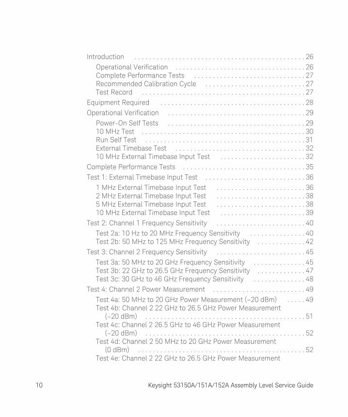
Introduction . . . . . . . . . . . . . . . . . . . . . . . . . . . . . . . . . . . . . . . . . . . . . . 26Operational Verification . . . . . . . . . . . . . . . . . . . . . . . . . . . . . . . . . . . 26Complete Performance Tests . . . . . . . . . . . . . . . . . . . . . . . . . . . . . . 27Recommended Calibration Cycle . . . . . . . . . . . . . . . . . . . . . . . . . . . 27Test Record . . . . . . . . . . . . . . . . . . . . . . . . . . . . . . . . . . . . . . . . . . . . 27
Equipment Required . . . . . . . . . . . . . . . . . . . . . . . . . . . . . . . . . . . . . . . 28Operational Verification . . . . . . . . . . . . . . . . . . . . . . . . . . . . . . . . . . . . . 29
Power-On Self Tests . . . . . . . . . . . . . . . . . . . . . . . . . . . . . . . . . . . . . 2910 MHz Test . . . . . . . . . . . . . . . . . . . . . . . . . . . . . . . . . . . . . . . . . . . . 30Run Self Test . . . . . . . . . . . . . . . . . . . . . . . . . . . . . . . . . . . . . . . . . . . 31External Timebase Test . . . . . . . . . . . . . . . . . . . . . . . . . . . . . . . . . . . 3210 MHz External Timebase Input Test . . . . . . . . . . . . . . . . . . . . . . . 32
Complete Performance Tests . . . . . . . . . . . . . . . . . . . . . . . . . . . . . . . . . 35Test 1: External Timebase Input Test . . . . . . . . . . . . . . . . . . . . . . . . . . . 36
1 MHz External Timebase Input Test . . . . . . . . . . . . . . . . . . . . . . . . 362 MHz External Timebase Input Test . . . . . . . . . . . . . . . . . . . . . . . . 385 MHz External Timebase Input Test . . . . . . . . . . . . . . . . . . . . . . . . 3810 MHz External Timebase Input Test . . . . . . . . . . . . . . . . . . . . . . . 39
Test 2: Channel 1 Frequency Sensitivity . . . . . . . . . . . . . . . . . . . . . . . . 40Test 2a: 10 Hz to 20 MHz Frequency Sensitivity . . . . . . . . . . . . . . . 40Test 2b: 50 MHz to 125 MHz Frequency Sensitivity . . . . . . . . . . . . . 42
Test 3: Channel 2 Frequency Sensitivity . . . . . . . . . . . . . . . . . . . . . . . . 45Test 3a: 50 MHz to 20 GHz Frequency Sensitivity . . . . . . . . . . . . . . 45Test 3b: 22 GHz to 26.5 GHz Frequency Sensitivity . . . . . . . . . . . . . 47Test 3c: 30 GHz to 46 GHz Frequency Sensitivity . . . . . . . . . . . . . . 48
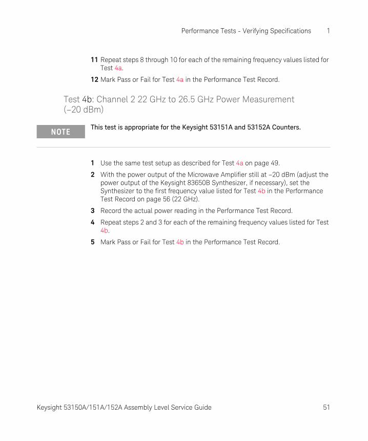
Test 4: Channel 2 Power Measurement . . . . . . . . . . . . . . . . . . . . . . . . . 49Test 4a: 50 MHz to 20 GHz Power Measurement (–20 dBm) . . . . . 49Test 4b: Channel 2 22 GHz to 26.5 GHz Power Measurement
(–20 dBm) . . . . . . . . . . . . . . . . . . . . . . . . . . . . . . . . . . . . . . . . . . . 51Test 4c: Channel 2 26.5 GHz to 46 GHz Power Measurement
(–20 dBm) . . . . . . . . . . . . . . . . . . . . . . . . . . . . . . . . . . . . . . . . . . . 52Test 4d: Channel 2 50 MHz to 20 GHz Power Measurement
(0 dBm) . . . . . . . . . . . . . . . . . . . . . . . . . . . . . . . . . . . . . . . . . . . . . 52Test 4e: Channel 2 22 GHz to 26.5 GHz Power Measurement
10 Keysight 53150A/151A/152A Assembly Level Service Guide

(0 dBm) . . . . . . . . . . . . . . . . . . . . . . . . . . . . . . . . . . . . . . . . . . . . .53Test 4f: Channel 2 30 GHz to 46 GHz Power Measurement
(0 dBm) . . . . . . . . . . . . . . . . . . . . . . . . . . . . . . . . . . . . . . . . . . . . .53Performance Test Record (Page 1 of 4) . . . . . . . . . . . . . . . . . . . . . . . . .54Performance Test Record (Page 2 of 4) . . . . . . . . . . . . . . . . . . . . . . . . .55Performance Test Record (Page 3 of 4) . . . . . . . . . . . . . . . . . . . . . . . . .56Performance Test Record (Page 4 of 4) . . . . . . . . . . . . . . . . . . . . . . . . .57
2 Service
Introduction . . . . . . . . . . . . . . . . . . . . . . . . . . . . . . . . . . . . . . . . . . . . . .60Returning the Counter to Keysight Technologies for Service . . . . . . . .61
Providing Repair Information . . . . . . . . . . . . . . . . . . . . . . . . . . . . . . .61Packing the Counter in the Original Packaging Materials . . . . . . . .62Packing the Counter in Commercially Available Packaging
Materials . . . . . . . . . . . . . . . . . . . . . . . . . . . . . . . . . . . . . . . . . . . .62Calibration Procedure . . . . . . . . . . . . . . . . . . . . . . . . . . . . . . . . . . . . . . .63
Equipment Required . . . . . . . . . . . . . . . . . . . . . . . . . . . . . . . . . . . . .63Pre-Troubleshooting Information . . . . . . . . . . . . . . . . . . . . . . . . . . . . . .65
Safety Considerations . . . . . . . . . . . . . . . . . . . . . . . . . . . . . . . . . . . .65Recommended Test Equipment . . . . . . . . . . . . . . . . . . . . . . . . . . . .66Repair Considerations . . . . . . . . . . . . . . . . . . . . . . . . . . . . . . . . . . . .66After Service Considerations . . . . . . . . . . . . . . . . . . . . . . . . . . . . . . .67Assembly Identification and Location . . . . . . . . . . . . . . . . . . . . . . . .68
Troubleshooting the Counter . . . . . . . . . . . . . . . . . . . . . . . . . . . . . . . . .70Power Supply Check . . . . . . . . . . . . . . . . . . . . . . . . . . . . . . . . . . . . .70Self-Test . . . . . . . . . . . . . . . . . . . . . . . . . . . . . . . . . . . . . . . . . . . . . . .72
3 Replacing Assemblies - Disassembly and Reassembly
Introduction . . . . . . . . . . . . . . . . . . . . . . . . . . . . . . . . . . . . . . . . . . . . . .78Tools Required . . . . . . . . . . . . . . . . . . . . . . . . . . . . . . . . . . . . . . . . . . . .79Do This First . . . . . . . . . . . . . . . . . . . . . . . . . . . . . . . . . . . . . . . . . . . . . .79Removing the Bumpers . . . . . . . . . . . . . . . . . . . . . . . . . . . . . . . . . . . . .80Removing the Handle and Handle Mounts . . . . . . . . . . . . . . . . . . . . . .81
Keysight 53150A/151A/152A Assembly Level Service Guide 11

Removing the Rear Bezel . . . . . . . . . . . . . . . . . . . . . . . . . . . . . . . . . . . . 82Removing the Shroud . . . . . . . . . . . . . . . . . . . . . . . . . . . . . . . . . . . . . . 84Removing the Front Bezel . . . . . . . . . . . . . . . . . . . . . . . . . . . . . . . . . . . 87Removing the Rear Panel Assembly . . . . . . . . . . . . . . . . . . . . . . . . . . . 88Removing the Cooling Fan . . . . . . . . . . . . . . . . . . . . . . . . . . . . . . . . . . . 91Replacing the Power Supply . . . . . . . . . . . . . . . . . . . . . . . . . . . . . . . . . 92
4 Replaceable Parts
Introduction . . . . . . . . . . . . . . . . . . . . . . . . . . . . . . . . . . . . . . . . . . . . . . 96Replaceable Parts . . . . . . . . . . . . . . . . . . . . . . . . . . . . . . . . . . . . . . . . . 97How To Order A Part . . . . . . . . . . . . . . . . . . . . . . . . . . . . . . . . . . . . . . . 98
Contacting Keysight Technologies . . . . . . . . . . . . . . . . . . . . . . . . . . 99Parts Identification . . . . . . . . . . . . . . . . . . . . . . . . . . . . . . . . . . . . . . . . 100
Reference Designations . . . . . . . . . . . . . . . . . . . . . . . . . . . . . . . . . 100Cabinet Parts and Hardware . . . . . . . . . . . . . . . . . . . . . . . . . . . . . . 100Accessories and Miscellaneous Items . . . . . . . . . . . . . . . . . . . . . . 100
5 Backdating
Introduction . . . . . . . . . . . . . . . . . . . . . . . . . . . . . . . . . . . . . . . . . . . . . 108
6 Specifications
Index . . . . . . . . . . . . . . . . . . . . . . . . . . . . . . . . . . . . . . . . . . . . . . . . . . . 111
12 Keysight 53150A/151A/152A Assembly Level Service Guide

List of Figures
Figure 1-1 External Timebase Test Setup . . . . . . . . . . . . . . . . . . .33Figure 1-2 External Timebase Test Setup . . . . . . . . . . . . . . . . . . .37Figure 1-3 10 Hz to 20 MHz Frequency Sensitivity Test Setup . .41Figure 1-4 50 MHz to 125 MHz Frequency Sensitivity Test
Setup . . . . . . . . . . . . . . . . . . . . . . . . . . . . . . . . . . . .42Figure 1-5 50 MHz to 20 GHz Frequency Sensitivity Test
Setup . . . . . . . . . . . . . . . . . . . . . . . . . . . . . . . . . . . .46Figure 1-6 50 MHz to 20 GHz (–20 dBm) Power Measurement
Test Setup . . . . . . . . . . . . . . . . . . . . . . . . . . . . . . . .50Figure 2-1 Calibrating the Counter . . . . . . . . . . . . . . . . . . . . . . . .63Figure 2-3 A4 DC Power Supply Test-Point Locations . . . . . . . . .70Figure 4-1 Keysight 53150A/151A/152A Exploded View —
Internal Parts . . . . . . . . . . . . . . . . . . . . . . . . . . . . .101Figure 4-2 Keysight 53150A/151A/152A Exploded View —
Cabinet and External Parts . . . . . . . . . . . . . . . . . .102Figure 4-3 Keysight 53150A/151A/152A Top View . . . . . . . . . .103
Keysight 53150A/151A/152A Assembly Level Service Guide 13

THIS PAGE HAS BEEN INTENTIONALLY LEFT BLANK.
14 Keysight 53150A/151A/152A Assembly Level Service Guide
List of Tables
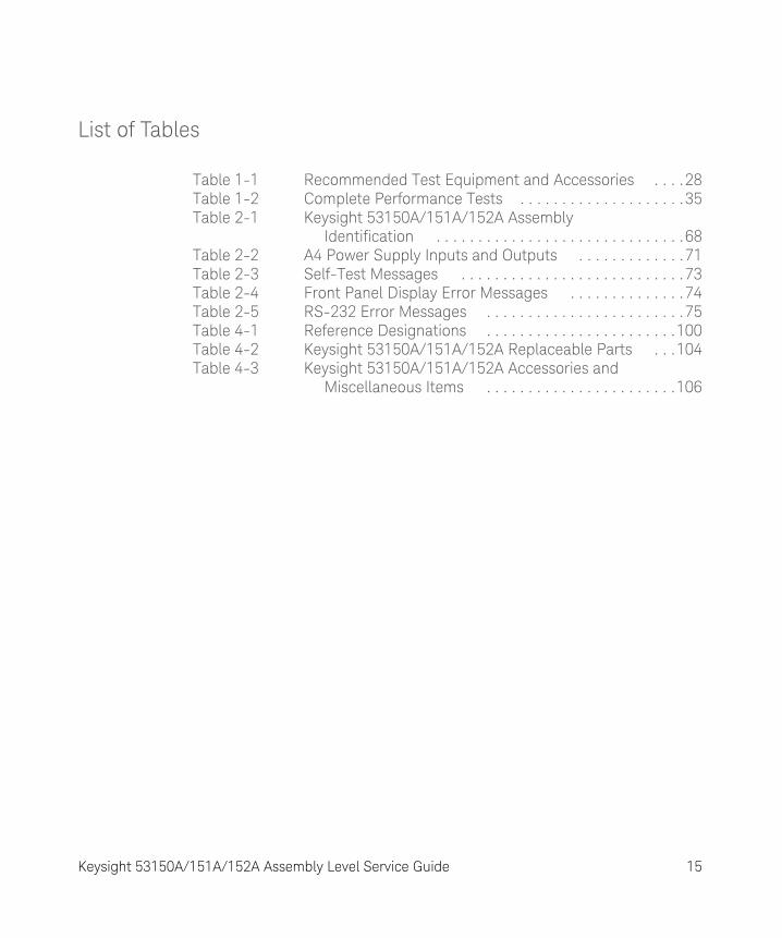
Table 1-1 Recommended Test Equipment and Accessories . . . .28Table 1-2 Complete Performance Tests . . . . . . . . . . . . . . . . . . . .35Table 2-1 Keysight 53150A/151A/152A Assembly
Identification . . . . . . . . . . . . . . . . . . . . . . . . . . . . . .68Table 2-2 A4 Power Supply Inputs and Outputs . . . . . . . . . . . . .71Table 2-3 Self-Test Messages . . . . . . . . . . . . . . . . . . . . . . . . . . .73Table 2-4 Front Panel Display Error Messages . . . . . . . . . . . . . .74Table 2-5 RS-232 Error Messages . . . . . . . . . . . . . . . . . . . . . . . .75Table 4-1 Reference Designations . . . . . . . . . . . . . . . . . . . . . . .100Table 4-2 Keysight 53150A/151A/152A Replaceable Parts . . .104Table 4-3 Keysight 53150A/151A/152A Accessories and
Miscellaneous Items . . . . . . . . . . . . . . . . . . . . . . .106
Keysight 53150A/151A/152A Assembly Level Service Guide 15

THIS PAGE HAS BEEN INTENTIONALLY LEFT BLANK.
16 Keysight 53150A/151A/152A Assembly Level Service Guide
Keysight 53150A/151A/152A Microwave Frequency CounterAssembly Level Service Guide
In This Guide
How to Use This Guide 18Description of the Microwave Frequency Counter 21Options 22Accessories Supplied and Available 23
This guide provides assembly-level service information for the Keysight 53150A, 53151A, and 53152A Counters.
17

In This Guide
How to Use This Guide
Repair Strategy
This service guide is designed to isolate failures to the assembly level only.
The Keysight 53150A/151A/152A Counter can be returned to Keysight for all service work, including troubleshooting, and verifying specifications. Contact your nearest Keysight Sales and Service Office for more details.
If you decide to service the Counter yourself, use the troubleshooting procedures in Chapter 2 (Service) and the disassembly and reassembly procedures in Chapter 3 (Replacing Assemblies - Disassembly and Reassembly). Then, use the calibration instructions in Chapter 2 to calibrate the Counter for peak-performance operation, and finally, perform all of the performance tests in Chapter 1 to verify that the Counter is operating to the specifications.
NOTEISD (Instrument Service Division) Emergency Response or Express Calibration Service is available for Keysight customers in the USA. If downtime is critical, you can receive your repaired Counter via overnight shipment. Call 1-800-403-0801, and ask for Emergency Response or Express Calibration Service. When your Counter is repaired, it is returned via overnight shipment at no extra charge.
NOTEIf the motherboard, the sampler, or the front-panel assembly are defective, the instrument must be returned to an Keysight Service Center for repair and recalibration.
18 Keysight 53150A/151A/152A Assembly Level Service Guide

In This Guide
Instrument Identification
The instrument is identified by the serial number on the rear panel. Keysight uses a two-part serial number with the first part (prefix) identifying a series of instruments and the second part (suffix) identifying a particular instrument within a series. Keysight-assigned alpha characters before the prefix identify the country in which the instrument was manufactured.
Instruments Covered by this Guide
This guide applies directly to Keysight 53150A, 53151A, and 53152A Counters that have the same serial number prefix(es) shown on the title page. If the serial number prefix of your Counter differs from that listed on the title page of this guide, there may be differences between this guide and your instrument.
Instruments having a higher serial prefix are covered (when required) by one or more manual-change sheets included with this guide. If a required change sheet is missing, contact your nearest Keysight Sales Office listed at the back of this guide.
Assembly-Level Service Guide Organization
This Assembly-Level Service Guide consists of a table of contents, a preface, six chapters, and an index. The page headers identify the chapters and sections of this manual. The chapter contents are summarized as follows:
Chapter 1, “Performance Tests - Verifying Specifications” provides procedures that verify the Counter operates properly and meets the Keysight 53150A/151A/152A specifications given in Chapter 6, “Specifications” in this guide.
Chapter 2, “Service” is divided into seven main sections that provide instructions for returning the Counter to Keysight for service, calibrating the Counter, and troubleshooting the assemblies in the Counter.
Chapter 3, “Replacing Assemblies - Disassembly and Reassembly” provides procedures for replacing defective assemblies and/or modules in the Counter.
Keysight 53150A/151A/152A Assembly Level Service Guide 19
In This Guide
Chapter 4, “Replaceable Parts” lists the replaceable parts contained in the Counter, and explains how to order replacement parts for your Counter.
Chapter 5, “Backdating” contains information required to adapt this manual for older instruments (to be provided when required).
Chapter 6, “Specifications” lists all the specifications and operating characteristics for the Keysight 53150A/151A/152A Counter.
How to Order Guides
The part number for this guide is listed on the Certification and Warranty page (page 4) and on the back cover of this guide.
20 Keysight 53150A/151A/152A Assembly Level Service Guide

In This Guide
Description of the Microwave Frequency Counter
The Keysight 53150A, 53151A, and 53152A Microwave Frequency Counters are capable of measuring frequencies from 10 Hz to 125 MHz on Channel 1 and from 50 MHz to 20 GHz (53150A), 26.5 GHz (53151A), and 46 GHz (53152A) on Channel 2. These frequency counters are also capable of measuring power on Channel 2 (in the same frequency ranges). All three Counters have a maximum frequency resolution of 1 Hz.
The Keysight 53150A/151A/152A provides GPIB and RS-232 serial interfaces and are suitable for bench-top and ATE operation.
The basic measurement functions of the Keysight 53150A/151A/152A include Frequency, Relative Frequency, Frequency Offset, and Power (including Power Offset and Relative Power). All of these features are accessible from the front panel and over the GPIB and RS-232 interfaces.
The Keysight 53150A/151A/152A includes the following additional measurement functions and features that are designed specifically for manufacturing and service applications:
– 1, 2, 5, and 10 MHz external reference capability
– Optional high-stability oven oscillator for high-accuracy needs and lengthened calibration cycles
– Frequency and power offset capabilities for relative measurements
– SCPI programming capability
– Battery and dc input option for operation in locations where AC power is unavailable
– Optional soft carrying case for safe transportation and mobile use
Programmable control is performed via an GPIB or an RS-232 serial interface. The GPIB and RS-232C ports are standard for the Keysight 53150A, 53151A, and 53152A.
Keysight 53150A/151A/152A Assembly Level Service Guide 21
In This Guide
Options
The options available for the Keysight 53150A/151A/152A are listed following this paragraph. Specifications for the options are listed in Chapter 6, “Specifications”. Options ordered with the Counter are installed at the factory and are ready for operation on delivery.
Hardware
– High Stability Oven Timebase, Option 001
– Battery/DC Power Input, Option 002
– Rack Mount Kit, Option 1CM (not installed)
– Soft Carrying Case, Option 007 (not installed)
Support
– 3-year Return to Keysight for Repair, Option W30
– 3-year Return to Keysight for Calibration, Option W32
– 3-year Return to Keysight for Standards Compliant Calibration, Option W34
– 5-year Return to Keysight for Repair, Option W50
– 5-year Return to Keysight for Calibration, Option W52
– 5-year Return to Keysight for Standards Compliant Calibration, Option W54
NOTEHardware options can be retrofitted at an Keysight Service Center. However, the cost to retrofit options is considerably higher than the cost of the same options when purchased with the instrument.
22 Keysight 53150A/151A/152A Assembly Level Service Guide

In This Guide
Accessories Supplied and Available
Accessories Supplied
– Power cord, 2.3 meters (part number dependent upon destination country)
– Fuse (Keysight P/N 2110-0007)
Accessories Available
– Accessories for use with Option 002 (Battery/DC Power Input):
– Automotive Power Adapter (Keysight P/N 53150-60214)
– Battery (Keysight P/N 53150-80010)
– Battery Charger (Keysight P/N 53150-60217) 115V(includes Automotive Power Adapter)
– Battery Charger (Keysight P/N 53150-60218) 230V(includes Automotive Power Adapter)
– GPIB Cables (Keysight P/N 10833A/B/C/D)
– RS-232 Cable (Keysight P/N 53150-60215)
– Soft Carrying Case (Keysight P/N 53150-80016) — same as Option 007
– Rack Mount Kit (Keysight P/N 53150-67001) — same as Option 1CM
Manuals Supplied
Keysight 53150A/151A/152A Operating Guide(Keysight P/N 53150-90013)
Keysight 53150A/151A/152A Programming Guide (Keysight P/N 53150-90014)
Keysight 53150A/151A/152A Assembly-Level Service Guide (Keysight P/N 53150-90015)
Keysight 53150A/151A/152A Assembly Level Service Guide 23

In This Guide
THIS PAGE HAS BEEN INTENTIONALLY LEFT BLANK.
24 Keysight 53150A/151A/152A Assembly Level Service Guide
Keysight 53150A/151A/152A Microwave Frequency CounterAssembly Level Service Guide
1 Performance Tests - Verifying Specifications
Introduction 26Equipment Required 28Operational Verification 29Complete Performance Tests 35Test 1: External Timebase Input Test 36Test 2: Channel 1 Frequency Sensitivity 40Test 3: Channel 2 Frequency Sensitivity 45Test 4: Channel 2 Power Measurement 49Performance Test Record (Page 1 of 4) 54Performance Test Record (Page 2 of 4) 55Performance Test Record (Page 3 of 4) 56Performance Test Record (Page 4 of 4) 57
25

1 Performance Tests - Verifying Specifications
Introduction
This chapter provides procedures to test the electrical performance of the Keysight 53150A/151A/152A. These procedures are based on the Counter specifications in Chapter 6, “Specifications”.
Two types of testing are provided:
– Operational Verification
– Complete Performance Tests
This chapter is organized as follows:
– Introduction pg. 26
– Equipment Required pg. 28
– Operational Verification pg. 29
– Complete Performance Tests pg. 35
– Performance Test Record pg. 54
Operational Verification
Operational Verification is an abbreviated series of tests that you can perform (instead of performing the Complete Performance Tests) to provide a high degree of confidence that the instrument is operating properly. Operational Verification is useful for incoming inspection, routine maintenance, and after instrument repair.
26 Keysight 53150A/151A/152A Assembly Level Service Guide

Performance Tests - Verifying Specifications 1
Complete Performance Tests
The Complete Performance Tests verify the specifications listed in Chapter 6, “Specifications”. All tests can be performed without opening the instrument.
Recommended Calibration Cycle
The Counter requires periodic verification of operation. Depending on the type of use, environmental conditions, aging, and measurement accuracy required, the Counter should be checked using the operational verification procedure at least once every year after the unit is first placed in operation. A full Calibration and Performance Test should be performed each time the Counter changes environment or if an assembly or module has been replaced.
Test Record
The results of the Operational Verification and the Complete Performance Tests should be recorded on a copy of the Performance Test Record, located at the end of the Complete Performance Test section in this chapter.
Keysight 53150A/151A/152A Assembly Level Service Guide 27
1 Performance Tests - Verifying Specifications
Equipment Required
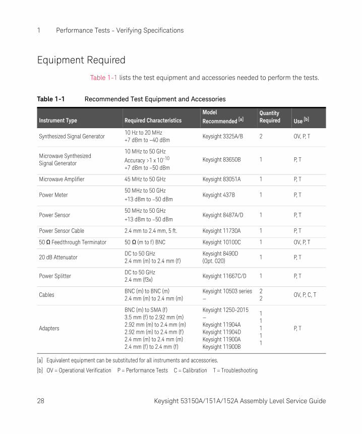
Table 1-1 lists the test equipment and accessories needed to perform the tests.
Table 1-1 Recommended Test Equipment and Accessories
Instrument Type Required CharacteristicsModelRecommended [a]
QuantityRequired Use [b]
Synthesized Signal Generator10 Hz to 20 MHz+7 dBm to –40 dBm
Keysight 3325A/B 2 OV, P, T
Microwave Synthesized Signal Generator
10 MHz to 50 GHz
Accuracy >1 x 10⁻¹⁰
+7 dBm to –50 dBmKeysight 83650B 1 P, T
Microwave Amplifier 45 MHz to 50 GHz Keysight 83051A 1 P, T
Power Meter50 MHz to 50 GHz+13 dBm to –50 dBm
Keysight 437B 1 P, T
Power Sensor50 MHz to 50 GHz+13 dBm to –50 dBm
Keysight 8487A/D 1 P, T
Power Sensor Cable 2.4 mm to 2.4 mm, 5 ft. Keysight 11730A 1 P, T
50 W Feedthrough Terminator 50 W (m to f ) BNC Keysight 10100C 1 OV, P, T
20 dB AttenuatorDC to 50 GHz2.4 mm (m) to 2.4 mm (f)
Keysight 8490D (Opt. 020)
1 P, T
Power SplitterDC to 50 GHz2.4 mm (f3x)
Keysight 11667C/D 1 P, T
CablesBNC (m) to BNC (m)2.4 mm (m) to 2.4 mm (m)
Keysight 10503 series—
22
OV, P, C, T
Adapters
BNC (m) to SMA (f )3.5 mm (f) to 2.92 mm (m)2.92 mm (m) to 2.4 mm (m)2.92 mm (m) to 2.4 mm (f )2.4 mm (m) to 2.4 mm (m)2.4 mm (f) to 2.4 mm (f )
Keysight 1250-2015—Keysight 11904AKeysight 11904DKeysight 11900AKeysight 11900B
11111
P, T
[a] Equivalent equipment can be substituted for all instruments and accessories.
[b] OV = Operational Verification P = Performance Tests C = Calibration T = Troubleshooting
28 Keysight 53150A/151A/152A Assembly Level Service Guide

Performance Tests - Verifying Specifications 1
Operational Verification
Operational Verification is an abbreviated series of tests that you can perform (instead of performing the Complete Performance Tests) to provide a high degree of confidence that the instrument is operating properly. Operational Verification is useful for incoming inspection, routine maintenance, and after instrument repair.
If you are not familiar with operating the Counter, you should review Chapter 1, “Getting Started,” in the Keysight 53150A/151A/152A Operating Guide. However, the procedures in this chapter are written so that little experience is necessary. These procedures should be followed in the order in which they appear.
Power-On Self Tests
1 Inspect the Counter for damage.
2 Make sure no cables are connected to the Counter’s inputs.
3 Connect the power cord to the Counter and the power source.
4 Turn on the Main ~ Power switch on the Counter’s rear panel.
5 Press and release the Power button on the front panel.
NOTEThis test is appropriate for the Keysight 53150A, 53151A, and 53152A Counters.
NOTESince the Counter’s power supply automatically senses the line voltage, there is no AC input-voltage setting.
NOTEIt is normal for the fan in the Counter to run when the Counter is in Standby mode. Power is supplied to the timebase whenever the Main ~ Power switch is on to maintain long-term measurement reliability, and the fan helps to maintain the timebase’s temperature stability.
Keysight 53150A/151A/152A Assembly Level Service Guide 29
1 Performance Tests - Verifying Specifications
6 Verify that the front-panel display shows the following:
– All segments of the front-panel display are temporarily activated.
– TESTING is displayed.
– SELF TEST OK is displayed.
– The model number of the Counter is displayed (a four-digit hex number is also displayed).
– GPIB ADDR nn (nn = a two digit number from 0 to 30) is displayed.
– CH2 NO SIGNAL is displayed.
7 If an error message is displayed, refer to the troubleshooting section in Chapter 2, “Service”.
8 Mark Pass or Fail in the Performance Test Record on page 54, Test 1.
10 MHz Test
1 Connect a BNC-to-BNC cable from the Reference 10MHz connector on the Counter’s rear panel to the CHANNEL 1 input connector on the front panel.
2 Press and release the Chan Select key (CH1 is displayed).
3 Verify that the display reads 10,000,000 Hz.
4 Mark Pass or Fail in the Performance Test Record on page 54, Test 2.
NOTETo ensure that the test results are valid, the Counter and the test equipment should be powered on for at least 30 minutes prior to beginning the tests. This allows the internal temperatures of the equipment and the timebase to stabilize.
30 Keysight 53150A/151A/152A Assembly Level Service Guide
Performance Tests - Verifying Specifications 1
Run Self Test
1 Disconnect all signal cables from the input and Reference 10MHz connectors.
2 Press and release the Shift key, and then press and release the Menu (Reset/Local) key.
3 Press the up- and/or down-arrow key(s) as many times as necessary until DO SELF TEST is displayed.
4 Press and release the Enter key.
5 If no errors are detected, SELF TEST OK is briefly displayed when the self test is completed. If any error messages are displayed, refer to the troubleshooting section in Chapter 2, “Service”.
6 Mark Pass or Fail in the Performance Test Record on page 54, Test 3.
NOTEThis test is appropriate for the Keysight 53150A, 53151A, and 53152A Counters.
Keysight 53150A/151A/152A Assembly Level Service Guide 31
1 Performance Tests - Verifying Specifications
External Timebase Test
This test verifies the 10 MHz external timebase specifications of the Counter by verifying that setting REF OSC to EXT allows the Counter to be synchronized to the external reference signal.
Equipment Required
Keysight 3325A/B Synthesizer (2)Keysight 10100C 50W Feedthrough TerminatorKeysight 10503 Series Coaxial Cables (BNC m to m) (2)
10 MHz External Timebase Input Test
1 Connect an Keysight 10503 series coaxial cable between the output of the first Keysight 3325A/B Synthesizer and the Reference 10MHz connector on the Counter’s rear panel (see Figure 1-2).
2 Connect the Keysight 10100C 50W Feedthrough Terminator to the Counter’s CHANNEL 1 input connector.
3 Connect an Keysight 10503 series coaxial cable between the output of the second Synthesizer and the Keysight 10100C 50W Feedthrough Terminator on the Counter’s CHANNEL 1 input connector.
NOTE– To ensure that the test results are valid, the Counter and the test equipment
should be powered on for at least 30 minutes prior to beginning the tests. This allows the internal temperatures of the equipment to stabilize.
– These tests are appropriate for the Keysight 53150A, 53151A, and 53152A Counters.
32 Keysight 53150A/151A/152A Assembly Level Service Guide

Performance Tests - Verifying Specifications 1
Figure 1-1 External Timebase Test Setup
4 Cycle the POWER button to preset the Counter.
5 Press the Shift key on the Counter’s front panel.
6 Press the Menu key on the Counter’s front panel.
7 If necessary, use the up- and down-arrow keys to cycle the display until it reads REF OSC> INT.
8 Press the right-arrow key once. INT begins to flash off and on.
9 Press the up- or down-arrow key once. INT changes to EXT.
10 Press the Enter key.
11 Press the Chan Select key once to select the CHANNEL 1 input connector.
Keysight53150A/51A/52ACounter
Keysight 3325A/B Synthesizer
Keysight 3325A/B Synthesizer
To Reference 10 MHzConnector
(Rear Panel)Output
Output
Channel 1
Keysight 53150A/151A/152A Assembly Level Service Guide 33
1 Performance Tests - Verifying Specifications
12 Set the first Synthesizer (the one connected to the Counter’s rear-panel Reference 10MHz connector) to output a 10 MHz, 1V rms, sine-wave signal.
13 Set the second Synthesizer (the one connected to the CHANNEL 1 input) to output a 2 MHz, 100 mV rms, sine-wave signal.
14 Press and release the Counter’s Reset/Local key.
15 Verify that the Counter displays a reading of approximately 2 MHz and that the Ext Ref annunciator is activated.
16 Mark Pass or Fail for Test 4 in the Performance Test Record on page 54.
This completes the Operational Verification.
NOTE– If you intend to perform the Complete Performance Tests next, do not
disconnect the cable from the Counter’s Reference 10 MHz connector. This connection is used in the Complete Performance Tests.
– Do not turn off the Counter if you intend to perform the Complete Performance tests. Turning the Counter off and back on resets the reference oscillator (REF OSC) selection to internal (INT) and the channel selection to CHANNEL 2.
34 Keysight 53150A/151A/152A Assembly Level Service Guide

Performance Tests - Verifying Specifications 1
Complete Performance Tests
The Complete Performance Tests verify the specifications of the Keysight 53150A/151A/152A Counter listed in Chapter 6, “Specifications”. All of these tests can be performed without opening the instrument. Table 1-2 lists a summary of the performance tests.
Record the results of the performance tests in the appropriate place on the Performance Test Record, which starts on page 54.
NOTETo ensure that the test results are valid, the Counter and the test equipment should be powered on for at least 30 minutes prior to beginning the tests. This allows the internal temperatures of the equipment and the timebase to stabilize.
Table 1-2 Complete Performance Tests
Page Number Test Description
Page 36 Test 1: External Timebase Input Test
Page 36 Test 2: Channel 1 Frequency Sensitivity
Page 45 Test 3: Channel 2 Frequency Sensitivity
Page 49 Test 4: Channel 2 Power Measurement
NOTEOther Counter measurement functions (e.g., Averaging) are mathemati-cally derived by the microprocessor from the parameters verified by these performance tests. If the Counter passes the performance tests, the other measurement functions are also functioning to specifications.
Keysight 53150A/151A/152A Assembly Level Service Guide 35

1 Performance Tests - Verifying Specifications
Test 1: External Timebase Input Test
This test verifies the 10 MHz external timebase specifications of the Counter by verifying that setting REF OSC to EXT allows the Counter to be synchronized to the external reference signal.
Equipment Required
Keysight 3325A/B Synthesizer (2)Keysight 10100C 50W Feedthrough TerminatorKeysight 10503 Series Coaxial Cables (BNC m to m) (2)
1 MHz External Timebase Input Test
1 Connect an Keysight 10503 series coaxial cable between the output of the first Keysight 3325A/B Synthesizer and the Reference 10MHz connector on the Counter’s rear panel (see Figure 1-2).
2 Connect the Keysight 10100C 50W Feedthrough Terminator to the Counter’s CHANNEL 1 input connector.
3 Connect an Keysight 10503 series coaxial cable between the output of the second Synthesizer and the Keysight 10100C 50W Feedthrough Terminator on the Counter’s CHANNEL 1 input connector.
NOTE– To ensure that the test results are valid, the Counter and the test equipment
should be powered on for at least 30 minutes prior to beginning the tests. This allows the internal temperatures of the equipment to stabilize.
– These tests are appropriate for the Keysight 53150A, 53151A, and 53152A Counters.
36 Keysight 53150A/151A/152A Assembly Level Service Guide

Performance Tests - Verifying Specifications 1
Figure 1-2 External Timebase Test Setup
4 Cycle the POWER button to preset the Counter.
5 Press the Shift key on the Counter’s front panel.
6 Press the Menu key on the Counter’s front panel.
7 If necessary, use the up- and down-arrow keys to cycle the display until it reads REF OSC> INT.
8 Press the right-arrow key once. INT begins to flash off and on.
9 Press the up- or down-arrow key once. INT changes to EXT.
10 Press the Enter key.
11 Press the Chan Select key once to select the CHANNEL 1 input connector.
Keysight53150A/51A/52ACounter
Keysight 3325A/B Synthesizer
Keysight 3325A/B Synthesizer
To Reference 10 MHzConnector
(Rear Panel)Output
Output
Channel 1
Keysight 53150A/151A/152A Assembly Level Service Guide 37
1 Performance Tests - Verifying Specifications
12 Set the first Synthesizer (the one connected to the Counter’s rear-panel Reference 10MHz connector) to output a 1 MHz, 1V rms, sine-wave signal.
13 Set the second Synthesizer (the one connected to the CHANNEL 1 input) to output a 2 MHz, 100 mV rms, sine-wave signal.
14 Press and release the Counter’s Reset/Local key.
15 Verify that the Counter displays a reading of approximately 2 MHz and that the Ext Ref annunciator is activated.
16 Mark Pass or Fail for Test 1a in the Performance Test Record on page 54.
2 MHz External Timebase Input Test
1 Change the frequency of the first Synthesizer (connected to the Counter’s rear-panel Reference 10 MHz connector) to 2 MHz.
2 Press and release the Counter’s Reset/Local key.
3 Verify that the Counter displays a reading of approximately 2 MHz and that the Ext Ref annunciator is activated.
4 Mark Pass or Fail for Test 1b in the Performance Test Record on page 54.
5 MHz External Timebase Input Test
1 Change the frequency of the first Synthesizer (connected to the Counter’s rear-panel Reference 10 MHz connector) to 5 MHz.
2 Press and release the Counter’s Reset/Local key.
3 Verify that the Counter displays a reading of approximately 2 MHz and that the Ext Ref annunciator is activated.
4 Mark Pass or Fail for Test 1c in the Performance Test Record on page 54.
38 Keysight 53150A/151A/152A Assembly Level Service Guide
Performance Tests - Verifying Specifications 1
10 MHz External Timebase Input Test
1 Change the frequency of the first Synthesizer (connected to the Counter’s rear-panel Reference 10 MHz connector) to 10 MHz.
2 Press and release the Counter’s Reset/Local key.
3 Verify that the Counter displays a reading of approximately 2 MHz and that the Ext Ref annunciator is activated.
4 Mark Pass or Fail for Test 1d in the Performance Test Record on page 54.
Keysight 53150A/151A/152A Assembly Level Service Guide 39

1 Performance Tests - Verifying Specifications
Test 2: Channel 1 Frequency Sensitivity
This set of tests verifies the frequency-sensitivity specifications of Channel 1 of the Keysight 53150A/151A/152A Counters.
Equipment Required
Keysight 3325A/B SynthesizerKeysight 83650B SynthesizerKeysight 437B Power MeterKeysight 8487A/D Power SensorKeysight 11730A Power Sensor CableKeysight 11667C Power SplitterKeysight 8490D (Opt. 020) 20 dB AttenuatorKeysight 1250-2015 BNC (m) to SMA (f) AdapterKeysight 11904A 2.92 mm (m) to 2.4 mm (m) AdapterKeysight 10503 Series Coaxial Cable (BNC m to m)2 mm (m) to 2 mm (f) Cable (2)
Test 2a: 10 Hz to 20 MHz Frequency Sensitivity
1 Connect an Keysight 10503 Series Coaxial Cable between the RF output connector on the Keysight 3325A/B Synthesizer and Counter’s CHANNEL 1 connector.
NOTEThis test is appropriate for the Keysight 53150A, 53151A, and 53152A Counters.
40 Keysight 53150A/151A/152A Assembly Level Service Guide

Performance Tests - Verifying Specifications 1
Figure 1-3 10 Hz to 20 MHz Frequency Sensitivity Test Setup
2 Verify that the Counter is still set to use an external reference signal (refer to steps 5 through 10 on page 37).
3 Set the output of the Synthesizer to the first frequency specified for Test 2a in the Performance Test Record on page 54 (10 Hz).
4 Set the power output of the Synthesizer to the first power value specified for Test 2a in the Performance Test Record on page 54 (–14.9 dBm) (40 mV).
5 Record the frequency value read on the Counter (±1 count) for Test 2a in the Performance Test Record on page 54.
6 Repeat steps 3, 4, and 5 for each of the remaining frequencies specified for Test 2a. Don’t forget to change the power level when performing the 1 KHz test (–19.2 dBm) (25 mV).
7 If all of the frequency values you recorded for Test 2a are correct, mark Pass in the Performance Test Record for Test 2a. If any of the frequency readings you recorded are incorrect, mark Fail in the Performance Test Record.
Keysight 3325A/B Synthesizer
Keysight53150A/51A/52ACounter
Output
Channel 1
ReferenceOutput
(Rear Panel)
To Reference 10 MHzConnector (Rear Panel)
Keysight 53150A/151A/152A Assembly Level Service Guide 41

1 Performance Tests - Verifying Specifications
ut
Test 2b: 50 MHz to 125 MHz Frequency Sensitivity
1 Connect an Keysight 10100C 50 W Feedthrough Terminator to the CHANNEL 1 input connector on the Counter’s front panel (refer to Figure 1-4 for steps 1 through 9).
Figure 1-4 50 MHz to 125 MHz Frequency Sensitivity Test Setup
NOTE– Do not disconnect the cable from the Counter’s Reference 10 MHz
connector. This connection is used in the following test.
– Do not turn off the Counter. Turning the Counter off and back on resets the reference oscillator (REF OSC) selection to internal (INT) and the channel selection to CHANNEL 2.
Keysight 11667CPower Splitter
Keysight 8487A/DPower Sensor
Keysight 8490D 20 dB AttenuatorKeysight 11904A 2.92 mm to 2.4 mm Adapter
Keysight 1250-2015 BNC to SMA Adapter
Keysight 83650B Synthesizer
Keysight 437B Power Meter
Keysight53150A/51A/52ACounter
inp
Channel 1
RF Output
ReferenceOutput
(Rear Panel)
To Reference 10 MHz(Rear Panel)
(See Note Below)
Keysight 10100C 50 Feedthrough
NOTEIf the 10 MHz reference output of the 53650B Synthesizer is not sufficient to drive the 53150A/51A/52A, reverse the test setup so that you drive the 83650B from the Counter.
42 Keysight 53150A/151A/152A Assembly Level Service Guide

Performance Tests - Verifying Specifications 1
2 Connect the Keysight 1250-2015 BNC (m) to SMA (f) Adapter to the Keysight 10100C Feedthrough Terminator on the Counter’s CHANNEL 1 connector.
3 Connect the Keysight 11904A 2.92 mm (m) to 2.4 mm (m) Adapter to the Keysight 1250-2015 Adapter.
4 Connect the Keysight 8490D 20 dB Attenuator to the Keysight 11904A Adapter.
5 Connect one of the output connectors on the Keysight 11667C Power Splitter to the Keysight 8490D Attenuator
6 Connect the Keysight 11900B 2.4 mm (f) to 2.4 mm (f) Adapter to the RF output of the Synthesizer.
7 Connect a 2.4 mm (m) to 2.4 mm (m) cable between the Adapter on the Synthesizer’s RF output connector and the input connector on the Keysight 11667C Power Splitter.
8 Connect the Keysight 8487A/D Power Sensor to the remaining output connector on the Keysight 11667C Power Splitter.
9 Connect the Keysight 11730A Power Sensor Cable between the Power Sensor and the sensor connector on the Keysight 437B Power Meter.
10 Verify that the Counter is still set to use an external reference signal (refer to steps 5 through 10 on page 37).
11 Set the output of the Keysight 83650B Synthesizer to the first frequency specified for Test 2b in the Performance Test Record on page 54 (50 MHz).
12 Set the power output of the Synthesizer (read on the Power Meter) to a power value 20 dBm above the value specified for Test 2b in the Performance Test Record on page 54 (+.8 dBm). (The added 20 dBm compensates for the 20 dB Attenuator.)
Keysight 53150A/151A/152A Assembly Level Service Guide 43
1 Performance Tests - Verifying Specifications
13 Record the frequency value read on the Counter (±1 count) for Test 2b in the Performance Test Record on page 54.
14 Set the output of the Synthesizer to 125 MHz, and repeat steps 11 through 13.
15 If both of the frequency values you recorded for Test 2b are correct, mark Pass in the Performance Test Record for Test 2b. If either of the frequency readings you recorded are incorrect, mark Fail in the Performance Test Record.
16 Disconnect the Keysight 10100C Feedthrough Terminator, the Keysight 1250-2015 Adapter, and the Keysight 11904A Adapter from the Counter’s CHANNEL 1 connector.
NOTE– Do not disconnect the rest of the test setup, as these connections are also
used in the Channel 2 Frequency Sensitivity test.
– Do not turn off the Counter. Turning the Counter off and back on resets the reference oscillator (REF OSC) selection to internal (INT).
44 Keysight 53150A/151A/152A Assembly Level Service Guide

Performance Tests - Verifying Specifications 1
Test 3: Channel 2 Frequency Sensitivity
This set of tests verifies the frequency-sensitivity specifications of Channel 2 of the Keysight 53150A/151A/152A Counters.
Equipment Required
Keysight 83650B SynthesizerKeysight 437B Power MeterKeysight 8487A/D Power SensorKeysight 11667C Power SplitterKeysight 11730A Power Sensor CableKeysight 8490D (Opt. 020) 20 dB AttenuatorKeysight 11904D 2.92 mm (m) to 2.4 mm (f) AdapterKeysight 10503 series Coaxial Cable (BNC m to m)2.4 mm (m) to 2.4 mm (m) Cable (2)
Test 3a: 50 MHz to 20 GHz Frequency Sensitivity
1 Connect the Keysight 11904D 2.92 mm (m) to 2.4 mm (f) Adapter to the Counter’s CHANNEL 2 input connector (refer to Figure 1-5 for steps 1 through 4).
2 Connect the Keysight 8490D Attenuator to the Keysight 11904D Adapter, as shown in Figure 1-5 (the other end of the Attenuator should remain connected to the Keysight 11667C Power Splitter).
3 Verify that the cable (with Adapter) is still connected between the RF output of the Keysight 83650B Synthesizer and the Power Splitter input connector.
4 Verify that the Power Sensor is still connected to the Power Splitter and that the Power Sensor Cable is still connected between the Power Sensor and the sensor connector on the Power Meter.
NOTEThis test is appropriate for the Keysight 53150A, 53151A, and 53152A Counters.
Keysight 53150A/151A/152A Assembly Level Service Guide 45

1 Performance Tests - Verifying Specifications
put
Figure 1-5 50 MHz to 20 GHz Frequency Sensitivity Test Setup
5 Verify that the Counter is still set to use an external reference signal (refer to steps 5 through 10 on page 37).
6 Set the output of the Keysight 83650B Synthesizer to the first frequency specified for Test 3a in the Performance Test Record on page 55 (50 MHz).
7 Set the power output of the Synthesizer (read on the Power Meter) to a power value 20 dBm above the value specified for Test 3a in the Performance Test Record on page 55 (0 dBm). (The added 20 dBm compensates for the 20 dB Attenuator.)
8 Record the frequency value read on the Counter (±1 count) for Test 3a in the Performance Test Record on page 55.
9 Repeat steps 6, through 8 for each of the remaining frequencies specified for Test 3a. Don’t forget to change the power level when performing the 400 MHz and 19 GHz tests (53150A, 53151A, and 53152A) and the 16 GHz and 19 GHz tests (53152A only).
Keysight 11667C Power Splitter
Keysight 8487A/D Power Sensor
Keysight 8490D 20 dB Attenuator(50 MHz to 40 GHz tests only)
Keysight 83650B Synthesizer
Keysight 437B Power Meter
Keysight z11904D Adapter
Keysight53150A/51A/52ACounter
in
Channel 2
RF Output
To ReferenceOutput
(Rear Panel)
To Reference 10 MHz(Rear Panel)
46 Keysight 53150A/151A/152A Assembly Level Service Guide

Performance Tests - Verifying Specifications 1
10 If all of the frequency values you recorded for Test 3a are correct, mark Pass in the Performance Test Record. If any of the frequency readings you recorded are incorrect, mark Fail in the Performance Test Record.
Test 3b: 22 GHz to 26.5 GHz Frequency Sensitivity
1 Use the same test setup as described for Test 3a on page 45.
2 Set the output of the Keysight 83650B Synthesizer to the first frequency specified for Test 3b in the Performance Test Record on page 55 (22 GHz).
3 Set the power output of the Synthesizer (read on the Power Meter) to a power value 20 dBm above the value specified for Test 3b in the Performance Test Record on page 55 (–5 dBm for the Keysight 53151A; –7 dBm for the Keysight 53152A). (The added 20 dBm compensates for the 20 dB Attenuator.)
4 Record the frequency value read on the Counter (±1 count) for Test 3b in the Performance Test Record on page 55.
5 Repeat steps 2 through 4 for each of the remaining frequencies specified for Test 3b.
6 If all of the frequency values you recorded for Test 3b are correct, mark Pass in the Performance Test Record for Test 3b. If any of the frequency readings you recorded are incorrect, mark Fail in the Performance Test Record.
NOTEThis test is appropriate for the Keysight 53151A and 53152A Counters.
Keysight 53150A/151A/152A Assembly Level Service Guide 47

1 Performance Tests - Verifying Specifications
Test 3c: 30 GHz to 46 GHz Frequency Sensitivity
1 Use the same test setup as described for Test 3a on page 45.
2 Set the output of the Keysight 83650B Synthesizer to the first frequency specified for Test 3c in the Performance Test Record on page 55 (30 GHz).
3 Set the power output of the Synthesizer (read on the Power Meter) to a power value 20 dBm above the value specified for Test 3c in the Performance Test Record on page 55 (–3 dBm). (The added 20 dBm compensates for the 20 dB Attenuator.)
4 Record the frequency value read on the Counter (±1 count) for Test 3c in the Performance Test Record on page 55.
5 Repeat steps 2, through 4 for each of the remaining frequencies specified for Test 3c. Don’t forget to change the power level for the 42, 44, and 46 GHz tests.
6 If all of the frequency values you recorded for Test 3c are correct, mark Pass in the Performance Test Record for Test 3c. If any of the frequency readings you recorded are incorrect, mark Fail in the Performance Test Record.
NOTEThis test is appropriate for the 53152A Counter only.
NOTE– Do not disconnect the Power Sensor or the Power Sensor Cable from the
power meter or the Power Splitter. These connections are reused in the following tests.
– Do not turn off the Counter. Turning the Counter off and back on resets the reference oscillator (REF OSC) selection to internal (INT).
48 Keysight 53150A/151A/152A Assembly Level Service Guide

Performance Tests - Verifying Specifications 1
Test 4: Channel 2 Power Measurement
This set of tests verifies the power-measurement specifications of Channel 2 of the Keysight 53150A/151A/152A Counters.
Equipment Required
Keysight 83650B SynthesizerKeysight 83051A Microwave AmplifierKeysight 437B Power MeterKeysight 8487A/D Power SensorKeysight 11730A Power Sensor CableKeysight 11667C Power SplitterKeysight 11904D 2.92 mm (m) to 2.4 mm (f) AdapterKeysight 11900A 2.4 mm (m) to 2.4 mm (m) AdapterKeysight 11900B 2.4 mm (f) to 2.4 mm (f) Adapter2.4 mm (m) to 2.4 mm (m) Cable (2)
Test 4a: 50 MHz to 20 GHz Power Measurement (–20 dBm)
1 Verify that the cable (with Adapter) is still connected to the RF output of the Keysight 83650B Synthesizer.
2 Connect the other end of the 2.4 mm cable to the input connector on the Keysight 83051A Microwave Amplifier.
3 Connect a 2.4 mm cable from the output of the Microwave Amplifier to the input connector on the Keysight 11667C Power Splitter.
4 Verify that the Power Sensor is still connected to the Power Splitter and that the Power Sensor Cable is still connected between the Power Sensor and the sensor connector on the Power Meter.
NOTEThis test is appropriate for the Keysight 53150A, 53151A, and 53152A Counters.
Keysight 53150A/151A/152A Assembly Level Service Guide 49

1 Performance Tests - Verifying Specifications
5 Connect the Keysight 11900A 2.4 mm (m) to 2.4 mm (m) Adapter to the Counter’s CHANNEL 2 input connector.
6 Connect the unused output of the Microwave Splitter to the Adapter on the Counter’s CHANNEL 2 input connector.
Figure 1-6 50 MHz to 20 GHz (–20 dBm) Power Measurement Test Setup
7 Verify that the Counter is still set to CHANNEL 2 (if necessary, use the Chan Select key on the Counter’s front panel to select CHANNEL 2).
8 Adjust the power output of the Synthesizer so that the power output of the Microwave Amplifier is –20 dBm.
9 Set the Synthesizer to the first frequency value listed for Test 4a in the Performance Test Record on page 56 (50 MHz).
10 Record the actual power reading in the Performance Test Record.
Keysight 11667C Power Splitter
Keysight 83051AMicrowave Amplifier
Keysight 8487A/D Power Sensor
Keysight 83650B Synthesizer
Keysight 11900B Adapter
Keysight53150A/51A/52ACounter
Channel 2
RF Output
Input
Keysight 437B Power Meter
50 Keysight 53150A/151A/152A Assembly Level Service Guide
Performance Tests - Verifying Specifications 1
11 Repeat steps 8 through 10 for each of the remaining frequency values listed for Test 4a.
12 Mark Pass or Fail for Test 4a in the Performance Test Record.
Test 4b: Channel 2 22 GHz to 26.5 GHz Power Measurement (–20 dBm)
1 Use the same test setup as described for Test 4a on page 49.
2 With the power output of the Microwave Amplifier still at –20 dBm (adjust the power output of the Keysight 83650B Synthesizer, if necessary), set the Synthesizer to the first frequency value listed for Test 4b in the Performance Test Record on page 56 (22 GHz).
3 Record the actual power reading in the Performance Test Record.
4 Repeat steps 2 and 3 for each of the remaining frequency values listed for Test 4b.
5 Mark Pass or Fail for Test 4b in the Performance Test Record.
NOTEThis test is appropriate for the Keysight 53151A and 53152A Counters.
Keysight 53150A/151A/152A Assembly Level Service Guide 51

1 Performance Tests - Verifying Specifications
Test 4c: Channel 2 26.5 GHz to 46 GHz Power Measurement (–20 dBm)
1 Use the same test setup as described for Test 4a on page 49.
2 With the power output of the Microwave Amplifier still at –20 dBm (adjust the power output of the Synthesizer, if necessary), set the Synthesizer to the first frequency value listed for Test 4c in the Performance Test Record on page 56 (30 GHz).
3 Record the actual power reading in the Performance Test Record.
4 Repeat steps 2 and 3 for each of the remaining frequency values listed for Test 4c.
5 Mark Pass or Fail for Test 4c in the Performance Test Record.
Test 4d: Channel 2 50 MHz to 20 GHz Power Measurement (0 dBm)
1 Use the same test setup as described for Test 4a on page 49.
2 Adjust the power output of the Synthesizer so that the power output of the Microwave Amplifier is 0 dBm.
3 Set the Synthesizer to the first frequency value listed for Test 4d in the Performance Test Record on page 57 (50 MHz).
4 Record the actual power reading in the Performance Test Record.
5 Repeat steps 2 through 4 for each of the remaining frequency values listed for Test 4d.
6 Mark Pass or Fail for Test 4d in the Performance Test Record.
NOTEThis test is appropriate for the Keysight 53152A Counter only.
NOTEThis test is appropriate for the Keysight 53150A, 53151A, and 53152A Counters.
52 Keysight 53150A/151A/152A Assembly Level Service Guide

Performance Tests - Verifying Specifications 1
Test 4e: Channel 2 22 GHz to 26.5 GHz Power Measurement (0 dBm)
1 Use the same test setup as described for Test 4a on page 49.
2 With the power output of the Microwave Amplifier still at 0 dBm (adjust the power output of the Synthesizer, if necessary), set the Synthesizer to the first frequency value listed for Test 4e in the Performance Test Record on page 57 (22 GHz).
3 Record the actual power reading in the Performance Test Record.
4 Repeat steps 2 and 3 for the remaining frequency values listed for Test 4e.
5 Mark Pass or Fail for Test 4e in the Performance Test Record.
Test 4f: Channel 2 30 GHz to 46 GHz Power Measurement (0 dBm)
1 Use the same test setup as described for Test 4a on page 49.
2 With the power output of the Microwave Amplifier still at 0 dBm (adjust the power output of the Synthesizer, if necessary), set the Synthesizer to the first frequency value listed for Test 4f in the Performance Test Record on page 57 (30 GHz).
3 Record the actual power reading in the Performance Test Record.
4 Repeat steps 2 and 3 for each of the remaining frequency values listed for Test 4f.
5 Mark Pass or Fail for Test 4f in the Performance Test Record.
NOTEThis test is appropriate for the Keysight 53151A and 53152A Counters.
NOTEThis test is appropriate for the Keysight 53152A Counter only.
Keysight 53150A/151A/152A Assembly Level Service Guide 53
1 Performance Tests - Verifying Specifications
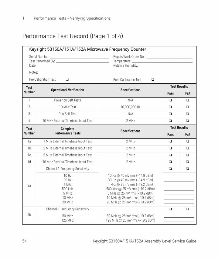
Performance Test Record (Page 1 of 4)
Keysight 53150A/151A/152A Microwave Frequency Counter
Serial Number: _________________________________________Test Performed By: _____________________________________Date: __________________________________________________
Repair/Work Order No.: ________________________________Temperature: __________________________________________Relative Humidity: _____________________________________
Notes: ____________________________________________________________________________________________________________
Pre Calibration Test ❏ Post Calibration Test ❏
Test Number
Operational Verification SpecificationsTest Resul ts
Pass Fail
1 Power on Self Tests N/A ❏ ❏
2 10 MHz Test 10,000,000 Hz ❏ ❏
3 Run Self Test N/A ❏ ❏
4 10 MHz External Timebase Input Test 2 MHz ❏ ❏
Test Number
CompletePerformance Tests
SpecificationsTest Resul ts
Pass Fail
1a 1 MHz External Timebase Input Test 2 MHz ❏ ❏
1b 2 MHz External Timebase Input Test 2 MHz ❏ ❏
1c 5 MHz External Timebase Input Test 2 MHz ❏ ❏
1d 10 MHz External Timebase Input Test 2 MHz ❏ ❏
2a
Channel 1 Frequency Sensitivity ❏ ❏
10 Hz30 Hz1 kHz
500 kHz5 MHz
10 MHz20 MHz
10 Hz @ 40 mV rms (–14.9 dBm)30 Hz @ 40 mV rms (–14.9 dBm)1 kHz @ 25 mV rms (–19.2 dBm)
500 kHz @ 25 mV rms (–19.2 dBm)5 MHz @ 25 mV rms (–19.2 dBm)
10 MHz @ 25 mV rms (–19.2 dBm) 20 MHz @ 25 mV rms (–19.2 dBm)
___________________________________________________________________________________________________________________________________________________
2b
Channel 1 Frequency Sensitivity ❏ ❏
50 MHz125 MHz
50 MHz @ 25 mV rms (–19.2 dBm)125 MHz @ 25 mV rms (–19.2 dBm)
__________________________________________
54 Keysight 53150A/151A/152A Assembly Level Service Guide

Performance Tests - Verifying Specifications 1
Performance Test Record (Page 2 of 4)
Test Number
CompletePerformance Tests
SpecificationsTest Resul ts
Pass Fail
3a
Channel 2 Frequency Sensitivity 53150A 53151A 53152A ❏ ❏
50 MHz100 MHz250 MHz300 MHz500 MHz
1 GHz2.5 GHz5 GHz
10 GHz12.4 GHz16 GHz18 GHz19 GHz20 GHz
–20 dBm""
–33 dBm""""""""
–29 dBm"
–20 dBm""
–33 dBm""""""""
–29 dBm"
–20 dBm""
–33 dBm""""""
–30 dBm"
–27 dBm"
______________________________________________________________________________________________________________________________________________________________________________________________________________________________________________________________________________________________________
3b
Channel 2 Frequency Sensitivity 53150A 53151A 53152A ❏ ❏
22 GHz24 GHz
26.5 GHz
N/AN/AN/A
–25 dBm""
–27 dBm""
_______________________________________________________________
3c
Channel 2 Frequency Sensitivity 53150A 53151A 53152A ❏ ❏
30 GHz34 GHz40 GHz42 GHz44 GHz46 GHz
N/AN/AN/AN/AN/AN/A
N/AN/AN/AN/AN/AN/A
–23 dBm""
–17 dBm""
______________________________________________________________________________________________________________________________
Keysight 53150A/151A/152A Assembly Level Service Guide 55
1 Performance Tests - Verifying Specifications
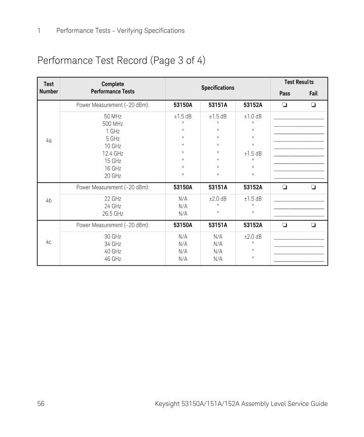
Performance Test Record (Page 3 of 4)
Test Number
CompletePerformance Tests
SpecificationsTest Resul ts
Pass Fail
4a
Power Measurement (–20 dBm): 53150A 53151A 53152A ❏ ❏
50 MHz500 MHz
1 GHz5 GHz
10 GHz12.4 GHz15 GHz16 GHz20 GHz
±1.5 dB""""""""
±1.5 dB""""""""
±1.0 dB""""
±1.5 dB"""
_____________________________________________________________________________________________________________________________________________________________________________________________
4b
Power Measurement (–20 dBm): 53150A 53151A 53152A ❏ ❏
22 GHz24 GHz
26.5 GHz
N/AN/AN/A
±2.0 dB""
±1.5 dB""
_______________________________________________________________
4c
Power Measurement (–20 dBm): 53150A 53151A 53152A ❏ ❏
30 GHz34 GHz40 GHz46 GHz
N/AN/AN/AN/A
N/AN/AN/AN/A
±2.0 dB"""
____________________________________________________________________________________
56 Keysight 53150A/151A/152A Assembly Level Service Guide

Performance Tests - Verifying Specifications 1
Performance Test Record (Page 4 of 4)
Test Number
CompletePerformance Tests
SpecificationsTest Resul ts
Pass Fail
4d
Power Measurement (0 dBm): 53150A 53151A 53152A ❏ ❏
50 MHz500 MHz
1 GHz5 GHz
10 GHz12.4 GHz15 GHz16 GHz20 GHz
±1.5 dB""""""""
±1.5 dB""""""""
±1.0 dB""""
±1.5 dB"""
_____________________________________________________________________________________________________________________________________________________________________________________________
4e
Power Measurement (0 dBm): 53150A 53151A 53152A ❏ ❏
22 GHz24 GHz
26.5 GHz
N/AN/AN/A
±2.0 dB""
±1.5 dB""
_______________________________________________________________
4f
Power Measurement (0 dBm): 53150A 53151A 53152A ❏ ❏
30 GHz34 GHz40 GHz46 GHz
N/AN/AN/AN/A
N/AN/AN/AN/A
±2.0 dB"""
____________________________________________________________________________________
Keysight 53150A/151A/152A Assembly Level Service Guide 57

1 Performance Tests - Verifying Specifications
THIS PAGE HAS BEEN INTENTIONALLY LEFT BLANK.
58 Keysight 53150A/151A/152A Assembly Level Service Guide
Keysight 53150A/151A/152A Microwave Frequency CounterAssembly Level Service Guide
2 Service
Introduction 60Returning the Counter to Keysight Technologies for Service 61Calibration Procedure 63Pre-Troubleshooting Information 65Troubleshooting the Counter 70
59

2 Service
Introduction
This chapter provides service information for your Keysight 53150A/151A/152A. It is divided into four major sections:
– Returning the Counter to Keysight Technologies for Service (page 61). This section provides you with step-by-step instructions on how to return the instrument for service.
– Calibration Procedure (page 63). This section provides step-by-step procedures for calibrating the Keysight 53150A/151A/152A.
– Pre-Troubleshooting Information (page 65). This section provides you with pertinent information such as safety considerations, recommended test equipment, repair and after-service considerations, and assembly identification and location.
– Troubleshooting the Counter (page 70). This section provides you with troubleshooting procedures that isolate the faulty assembly or module. Replacement and recalibration of most modules can only be performed at an authorized Keysight Technologies Service Center.
If the instrument is under warranty, return it to Keysight for service. Refer to “Returning the Counter to Keysight Technologies for Service” on page 61. If you decide to troubleshoot the instrument yourself, refer to the section titled “Troubleshooting the Counter” on page 70.
60 Keysight 53150A/151A/152A Assembly Level Service Guide
Service 2
Returning the Counter to Keysight Technologies for Service
Providing Repair Information
Before shipping the Counter to an Keysight office for service or repair, call the nearest Keysight Sales Office to make arrangements. Then, tag and package the Keysight 53150A/151A/152A for shipment.
1 Write the following information on a tag:
– Owner’s name and address
– Counter model number
– Complete serial number
– Description of service required or failure indications
2 Attach the tag to the instrument.
3 Pack the instrument.
If the original packaging materials are available, use the procedure titled “Packing the Counter in the Original Packaging Materials” If the original packaging materials are not available, you can order new packaging materials from an Keysight Sales Office. The new packaging materials are identical to those used by the factory when packaging new instruments. To use commercially available packaging materials, use the procedure titled “Packing the Counter in Commercially Available Packaging Materials.” Both procedures are on the following page.
NOTEISD (Instrument Service Division) Emergency Response or Express Calibration Service is available for Keysight customers in the USA. If downtime is critical, you can receive your repaired Counter via overnight shipment. Call 1-800-403-0801, and ask for Emergency Response or Express Calibration Service. When your Counter is repaired, it is returned via overnight shipment at no extra charge.
Keysight 53150A/151A/152A Assembly Level Service Guide 61

2 Service
Packing the Counter in the Original Packaging Materials
To prevent shipping damage, it is best to repack the Counter in its original packaging. In any correspondence, refer to the Counter by the model number and the complete serial number.
1 Disconnect the power cord, probes, cables, or other accessories attached to the instrument.
2 Make sure the folded corrugated spacer (which normally contains the manuals) is in the box to ensure proper fitting.
3 Make sure one of the polystyrene blocks is in its proper position in the box.
4 Place the instrument, front panel end first, on the polystyrene block.
5 Place the other polystyrene block on top of the rear end of the instrument to secure it.
6 Do not return the manuals with the instrument. Return an accessory only when it is a part of the failure symptoms.
7 Seal the shipping container securely.
Packing the Counter in Commercially Available Packaging Materials
If the original factory packaging materials are not available, use the following procedure to pack the Counter in commercially available shipping materials.
1 Wrap the instrument in heavy paper or plastic.
2 Place the instrument in a strong shipping container. Use a double-walled carton made of at least 350 lb. test material.
3 Protect the control panel with cardboard.
4 Add a layer of shock-absorbing material that is 3 to 4 inches (70 to 100 mm) thick around all sides of the instrument cushion it and to prevent it from moving within the container
5 Seal the shipping container securely.
6 Mark the shipping container FRAGILE.
62 Keysight 53150A/151A/152A Assembly Level Service Guide

Service 2
Calibration Procedure
There is only one calibration procedure that can be performed outside of an Keysight authorized service facility. The following procedure describes how to calibrate the Counter’s timebase.
Equipment Required
10 MHz Reference StandardNon-metallic adjustment tool for slotted screw headKeysight 10503 series Coaxial Cable
1 Connect an Keysight 10503 series coaxial cable from the output of your 10 MHz frequency standard to the Channel 1 input on the Counter’s front panel.
2 If there is a label covering the calibration adjustment access hole, remove it (see Figure 2-1).
Figure 2-1 Calibrating the Counter
NOTEThe Counter should be powered on for at least 30 minutes prior to beginning the calibration procedure. This allows the internal temperature of the Counter and its timebase to stabilize.
CalibrationAccess Hole
Keysight 53150A/151A/152A Assembly Level Service Guide 63
2 Service
3 Insert a non-metallic slotted adjustment tool through the hole in the lower-right side of the Counter’s cover and into the slot in the timebase calibration screw.
4 Turn the calibration screw clockwise to increase the Counter’s reading or counter-clockwise to decrease the reading until the frequency value displayed on the Counter’s front panel is exactly 10,000,000 Hz.
64 Keysight 53150A/151A/152A Assembly Level Service Guide

Service 2
Pre-Troubleshooting Information
This section contains the following pertinent troubleshooting information:
– Safety Considerations
– Recommended Test Equipment
– Repair Considerations
– After Service Considerations
– Assembly Identification and Location
Safety Considerations
Although this instrument has been designed in accordance with international safety standards, this guide contains information, cautions, and warnings which must be followed to ensure safe operation and to retain the instrument in a safe condition. Service instructions, and adjustment procedures requiring removal of the instrument cover, are for use by service-trained personnel only. To avoid dangerous electric shock, do not perform any servicing or make any adjustments with the cover removed, unless qualified to do so.
Any maintenance and repair of the opened instrument under voltage should be avoided as much as possible and, if necessary, should be carried out only by a skilled person who is aware of the hazards involved (for example, fire and electric shock).
WARNINGBEFORE APPLYING AC POWER, THE INSTRUMENT AND ALL PROTECTIVE EARTH TERMINALS, EXTENSION CORDS, AUTO TRANSFORMERS, AND DEVICES CONNECTED TO THE INSTRUMENT SHOULD BE CONNECTED TO A PROTECTIVE EARTH GROUNDED SOCKET.
ANY INTERRUPTION OF THE PROTECTIVE GROUNDING CONDUCTOR INSIDE OR OUTSIDE THE INSTRUMENT OR DISCONNECTION OF THE PROTECTIVE EARTH TERMINAL WILL CAUSE A POTENTIAL SHOCK HAZARD THAT COULD RESULT IN PERSONAL INJURY. INTENTIONAL INTERRUPTION IS PROHIBITED.
Keysight 53150A/151A/152A Assembly Level Service Guide 65
2 Service
Recommended Test Equipment
Test equipment recommended for testing and troubleshooting the Keysight 53150A/151A/152A is listed in Chapter 1, “Performance Tests - Verifying Specifications”. Substitute equipment may be used if it meets or exceeds the required characteristics listed in Table 2-1.
Repair Considerations
Electrostatic Discharge
Electronic components and assemblies in the Keysight 53150A/151A/152A can be permanently degraded or damaged by electrostatic discharge. Use the following precautions when servicing the instrument:
1 ENSURE that static-sensitive devices or assemblies are serviced at static-safe work stations providing proper grounding for service personnel.
2 ENSURE that static-sensitive devices or assemblies are stored in static shielding bags or containers.
3 DO NOT wear clothing subject to static-charge buildup, such as wool or synthetic materials.
4 DO NOT handle components or assemblies in carpeted areas.
5 DO NOT remove an assembly or component from its static shielding protection until you are ready to install it.
6 AVOID touching component leads (handle by packaging only).
Surface Mount Repair
None of the assemblies in the Counter that use surface-mount components can be repaired outside of authorized Keysight Service Centers. Any attempt to repair these assemblies voids the Keysight factory warranty and makes the assemblies ineligible for return credit.
Disassembly and Reassembly Specifics
Refer to Chapter 3 of this guide, “Replacing Assemblies - Disassembly and Reassembly,” for complete disassembly and reassembly instructions, and Chapter 4, “Replaceable Parts” for an exploded view of the instrument’s parts.
66 Keysight 53150A/151A/152A Assembly Level Service Guide
Service 2
After Service Considerations
Product Safety Checks
The following safety checks must be performed after any troubleshooting and repair procedures have been completed to ensure the safe operation of the instrument.
1 VISUAL INSPECTION. Visually inspect the interior of the instrument for any signs of abnormal internally generated heat, such as discolored printed circuit boards or components, damaged insulation, or evidence of arcing. Determine and remedy the cause of any such condition.
2 GROUND CONTINUITY TEST. Plug the power cord into the rear- panel power receptacle. (DO NOT connect the instrument to AC power at this time.) Using a suitable ohmmeter, check resistance from the instrument's metallic connection (such as the rear panel or BNC ground collar) to the ground pin on the power cord plug. The reading must be less than 1Ω. Flex the power cord while making this measurement to determine whether intermittent discontinuities exist.
3 Check any indicated front- or rear-panel ground terminals marked, using the above procedure.
4 INSULATION RESISTANCE TEST. Tie the line and neutral pins of the power cord plug together. Measure the resistance from the instrument enclosure (chassis) to the line and neutral pins of the power cord plug. The minimum acceptable resistance is 2 MΩ. Replace any component which results in a failure.
Product Performance Checks
After replacement of any functional assembly, perform the operational verification test in Chapter 1 of this guide, “Performance Tests - Verifying Specifications.”
WARNINGTHE RESISTANCE CHECKS DESCRIBED IN THE FOLLOWING TEXT REQUIRE THAT THE POWER CORD BE CONNECTED TO THE INSTRUMENT AND THAT AC POWER BE DISCONNECTED. BE SURE THAT THE POWER CORD IS NOT CONNECTED TO AN AC POWER SOURCE BEFORE PERFORMING ANY SAFETY CHECKS.
Keysight 53150A/151A/152A Assembly Level Service Guide 67

2 Service
Assembly Identification and Location
The assembly number, name, and Keysight part number for each of the Keysight 53150A, 53151A, and 53152A assemblies are listed in Table 2-1. Figure 2-2 illustrates the replaceable assemblies in the Keysight 53150A/151A/152A.
Table 2-1 Keysight 53150A/151A/152A Assembly Identification
Assembly Name Keysight Part No.
A1 Adapter (53152A only) 53152-80001
A2 Cooling Fan Assembly 53150-80012
A3 Standby Power Switch Assembly 53150-80013
A4 Battery Housing Assembly[a]
[a] With Option 002 (Battery Option) only.
53150-00002
A5 DC/DC Converter PCB[a] 53150-60004
A6 Battery[a] 53150-80010
A7 Battery Sled Assembly[a] 53150-00004
A8 Battery Cover Assembly 53150-00003
A9 Rear Panel Assembly —
A10 Power Entry Module Assembly 53150-40007
A11 Power Supply Assembly 0950-3299
A12 Rear Panel Power Switch Assembly 53150-60220
68 Keysight 53150A/151A/152A Assembly Level Service Guide

Service 2
Figure 2-2 Replaceable Assembly Locations — Top Internal View
A10
A12
A9 A8
A7
A5
A4
A2
A6
A1
A3
A11
Keysight 53150A/151A/152A Assembly Level Service Guide 69
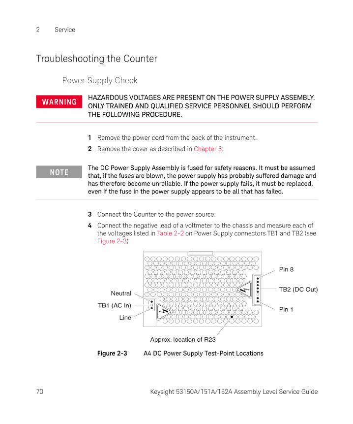
2 Service
Troubleshooting the Counter
Power Supply Check
1 Remove the power cord from the back of the instrument.
2 Remove the cover as described in Chapter 3.
3 Connect the Counter to the power source.
4 Connect the negative lead of a voltmeter to the chassis and measure each of the voltages listed in Table 2-2 on Power Supply connectors TB1 and TB2 (see Figure 2-3).
Figure 2-3 A4 DC Power Supply Test-Point Locations
WARNINGHAZARDOUS VOLTAGES ARE PRESENT ON THE POWER SUPPLY ASSEMBLY. ONLY TRAINED AND QUALIFIED SERVICE PERSONNEL SHOULD PERFORM THE FOLLOWING PROCEDURE.
NOTEThe DC Power Supply Assembly is fused for safety reasons. It must be assumed that, if the fuses are blown, the power supply has probably suffered damage and has therefore become unreliable. If the power supply fails, it must be replaced, even if the fuse in the power supply appears to be all that has failed.
Neutral
TB1 (AC In)
Line
Pin 8
TB2 (DC Out)
Pin 1
Approx. location of R23
70 Keysight 53150A/151A/152A Assembly Level Service Guide
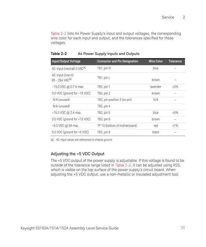
Service 2
Table 2-2 lists A4 Power Supply's input and output voltages, the corresponding wire color for each input and output, and the tolerances specified for these voltages.
Adjusting the +5 VDC Output
The +5 VDC output of the power supply is adjustable. If this voltage is found to be outside of the tolerance range listed in Table 2-2, it can be adjusted using R23, which is visible on the top surface of the power supply’s circuit board. When adjusting the +5 VDC output, use a non-metallic or insulated adjustment tool.
Table 2-2 A4 Power Supply Inputs and Outputs
Input/Output Vol tage Connector and Pin Designation Wire Color Tolerance
AC-input (neutral) 0 VAC[a]
[a] AC-input values are referenced to chassis ground.
TB1, pin N blue —
AC-input (line in)
85 - 264 VAC[a] TB1, pin Lbrown —
–15.0 VDC @ 0.7 A max. TB2, pin 1 lavender ±3%
0.0 VDC (ground for –15 VDC) TB2, pin 2 brown —
N/A (unused) TB2, pin position 3 (no pin) N/A —
N/A (unused) TB2, pin 4
+15.0 VDC @ 2 A max. TB2, pin 5 blue ±5%
0.0 VDC (ground for +15 VDC) TB2, pin 6 brown —
+5.0 VDC @ 5A max. TP 10 (bottom of motherboard) red ±1%
0.0 VDC (ground for +5 VDC) TB2, pin 8 black —
Keysight 53150A/151A/152A Assembly Level Service Guide 71

2 Service
Self-Test
The Counter performs a Self-Test procedure when it is powered on. The Self-Test can also be invoked from the Counter’s Menu.
Running the Self Test
1 Disconnect all cables connected to the Counter’s front and rear signal connectors.
2 Turn on the Main ~ Power switch on the Counter’s rear panel.
3 Press and release the Power button on the front panel.
4 Observe the front-panel display and note any error messages displayed.
5 When CH 2 NO SIGNAL is displayed, press and release the Shift key, and then press and release the Menu key.
6 Press the up-arrow key or the down-arrow key repeatedly until DO SELF TEST is displayed, and then press and release the Enter key.
7 Observe the front-panel display and note any error messages displayed.
72 Keysight 53150A/151A/152A Assembly Level Service Guide
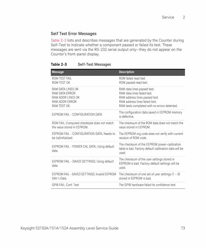
Service 2
Self Test Error Messages
Table 2-3 lists and describes messages that are generated by the Counter during Self-Test to indicate whether a component passed or failed its test. These messages are sent via the RS-232 serial output only—they do not appear on the Counter’s front-panel display.
Table 2-3 Self-Test Messages
Message Description
ROM TEST FAILROM TEST OK
ROM failed read test.ROM passed read test.
RAM DATA LINES OKRAM DATA ERRORRAM ADDR LINES OKRAM ADDR ERRORRAM TEST OK
RAM data lines passed test.RAM data lines failed test.RAM address lines passed test.RAM address lines failed test.RAM tests completed with no errors detected.
EEPROM FAIL - CONFIGURATION DATAThe configuration data saved in EEPROM memory is defective.
ROM FAIL; Computed checkbyte does not match the value stored in EEPROM.
The checksum of the ROM data does not match the value stored in EEPROM.
EEPROM FAIL - CONFIGURATION DATA; Needs to be (re)initialized.
The EEPROM org code does not verify with current revision of ROM code.
EEPROM FAIL - POWER CAL DATA; Using default data
The checksum of the EEPROM power-calibration table is bad. Factory default calibration data will be used.
EEPROM FAIL - SAVED SETTINGS; Using default data
The checksum of the user settings stored in EEPROM is bad. Factory default settings will be used.
EEPROM FAIL - SAVED SETTINGS; Invalid EEPROM SAV n Data.
The checksum of one set of user settings (1 – 9) stored in EEPROM is bad.
GPIB FAIL; Conf. Test The GPIB hardware failed its confidence test.
Keysight 53150A/151A/152A Assembly Level Service Guide 73

2 Service
Table 2-4 and Table 2-5 list and describe the messages that are generated by the Counter during Self-Test or during operation to indicate that a problem has been detected. These messages are displayed on the Counter’s front-panel display and are also sent via the RS-232 serial output (in many cases, the exact message text that is displayed on the front panel is a condensed form of the message that is sent via RS-232).
Table 2-4 Front Panel Display Error Messages
Message Description
12V FAIL The +12 VDC output from the power supply is not within specifications.
–12V FAIL The –12 VDC output from the power supply is not within specifications.
–5V FAIL The –5 VDC output from the power supply is not within specifications.
ADC FAIL Failure detected in the ADC.
PATH FAIL Failure detected in the Channel 1 signal path.
THRS FAIL Failure detected in the Channel 1 threshold circuit.
THRS FAIL Failure detected in the Channel 2 RF threshold circuit.
THRS THRU Failure detected in the Channel 2 through-path threshold circuit.
THRS HET Failure detected in the Channel 2 heterodyne-path threshold circuit.
EEP WRT FAIL Failure detected while writing to EEPROM.
FPANEL FAIL The front panel or its interconnecting cable is defective or not properly connected.
FPGA FAIL Failure detected in the FPGA (Field Programmable Gate Array).
GPIB FAIL Failure detected in the GPIB hardware.
HET PATH FAIL Failure detected in the heterodyne-path circuit.
IIC FAIL An attempt to write to the LCD display failed.
INSTCFG FAIL The instrument’s configuration data is missing or has become corrupted.
OVERTEMP The Counter’s internal temperature is above the acceptable limit.
PWR CAL FAIL The instrument’s power-calibration data is missing or corrupted.
PWR CKT FAIL Failure detected in the Channel 2 power-measurement circuit.
RAM FAIL Failure detected in RAM.
ROM FAIL Failure detected in ROM.
74 Keysight 53150A/151A/152A Assembly Level Service Guide
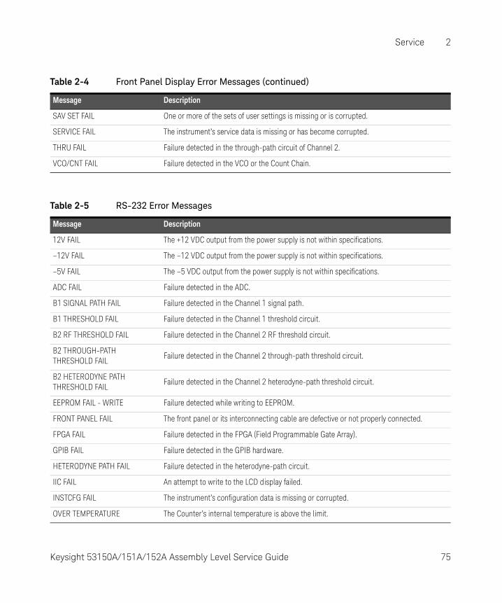
Service 2
SAV SET FAIL One or more of the sets of user settings is missing or is corrupted.
SERVICE FAIL The instrument’s service data is missing or has become corrupted.
THRU FAIL Failure detected in the through-path circuit of Channel 2.
VCO/CNT FAIL Failure detected in the VCO or the Count Chain.
Table 2-4 Front Panel Display Error Messages (continued)
Message Description
Table 2-5 RS-232 Error Messages
Message Description
12V FAIL The +12 VDC output from the power supply is not within specifications.
–12V FAIL The –12 VDC output from the power supply is not within specifications.
–5V FAIL The –5 VDC output from the power supply is not within specifications.
ADC FAIL Failure detected in the ADC.
B1 SIGNAL PATH FAIL Failure detected in the Channel 1 signal path.
B1 THRESHOLD FAIL Failure detected in the Channel 1 threshold circuit.
B2 RF THRESHOLD FAIL Failure detected in the Channel 2 RF threshold circuit.
B2 THROUGH-PATH THRESHOLD FAIL
Failure detected in the Channel 2 through-path threshold circuit.
B2 HETERODYNE PATH THRESHOLD FAIL
Failure detected in the Channel 2 heterodyne-path threshold circuit.
EEPROM FAIL - WRITE Failure detected while writing to EEPROM.
FRONT PANEL FAIL The front panel or its interconnecting cable are defective or not properly connected.
FPGA FAIL Failure detected in the FPGA (Field Programmable Gate Array).
GPIB FAIL Failure detected in the GPIB hardware.
HETERODYNE PATH FAIL Failure detected in the heterodyne-path circuit.
IIC FAIL An attempt to write to the LCD display failed.
INSTCFG FAIL The instrument’s configuration data is missing or corrupted.
OVER TEMPERATURE The Counter’s internal temperature is above the limit.
Keysight 53150A/151A/152A Assembly Level Service Guide 75

2 Service
PWR CAL FAIL The instrument’s power-calibration data is missing or corrupted.
POWER METER FAIL Failure detected in the Channel 2 power-measurement circuit.
RAM FAIL Failure detected in RAM.
ROM FAIL Failure detected in ROM.
SAV SET FAIL One or more of the sets of user settings is missing or corrupted.
SERVICE FAIL The instrument’s service data is missing or corrupted.
THRU PATH FAIL Failure detected in the through-path circuit of Channel 2.
VCO/COUNT CHAIN FAIL Failure detected in the VCO or the Count Chain.
Table 2-5 RS-232 Error Messages (continued)
Message Description
76 Keysight 53150A/151A/152A Assembly Level Service Guide

Keysight 53150A/151A/152A Microwave Frequency CounterAssembly Level Service Guide
3 Replacing Assemblies - Disassembly and Reassembly
Introduction 78Tools Required 79Do This First 79Removing the Bumpers 80Removing the Handle and Handle Mounts 81Removing the Rear Bezel 82Removing the Shroud 84Removing the Front Bezel 87Removing the Rear Panel Assembly 88Removing the Cooling Fan 91Replacing the Power Supply 92
77

3 Replacing Assemblies - Disassembly and Reassembly
Introduction
This chapter provides instructions for removing major assemblies in the Keysight 53150A/151A/152A. To install an assembly, apply the removal instructions in reverse.
The following disassembly and repair procedures are provided:
– Removing the Bumpers pg. 80
– Removing the Handle and Handle Mounts pg. 81
– Removing the Rear Bezel pg. 82
– Removing the Shroud pg. 84
– Removing the Rear Panel Assembly pg. 88
– Removing the Cooling Fan pg. 91
– Replacing the Power Supply pg. 92
Part numbers for all replaceable parts and assemblies are provided in Chapter 4, “Replaceable Parts”.
WARNINGHAZARDOUS VOLTAGES ARE PRESENT ON THE POWER SUPPLY ASSEMBLY. DISCONNECT THE COUNTER FROM THE POWER SOURCE, AND WAIT AT LEAST SIX MINUTES BEFORE WORKING INSIDE THE INSTRUMENT.
CAUTIONDo not replace assemblies when the Counter is operating to prevent damage to components.
NOTEUnless otherwise stated, directional referents in the procedures in this chapter are accurate when viewing the Counter from the front.
78 Keysight 53150A/151A/152A Assembly Level Service Guide

Replacing Assemblies - Disassembly and Reassembly 3
Tools Required
The following tools are required for the removal/replacement procedures in this chapter:
– #1 Phillips screwdriver
– #2 Phillips screwdriver
– TORX® 15 (T15) hand screwdriver
– 1/4-inch open-end or box wrench
– 1/4-inch nut driver
– 5/16-inch nut driver
– Needle-nose pliers
Do This First
Perform the following steps before beginning any of the removal and replacement procedures:
1 If the Counter is on, press and release the POWER button on the front panel, and then set the Main ~ Power switch on the rear panel to “0” (off).
2 Disconnect the AC power cord from the AC input socket on the rear panel.
3 If the Counter has the Battery Option (002) installed, remove the battery sled, and disconnect any DC input cable from the EXT DC connector on the rear panel.
CAUTIONWhile most of the hardware used in the Counter is SAE, the four TORX screws that attach the handle mounts to the Counter are metric. To avoid damage to the threaded holes in the chassis that handle mount screws fit in, be sure to use the correct screws.
Keysight 53150A/151A/152A Assembly Level Service Guide 79
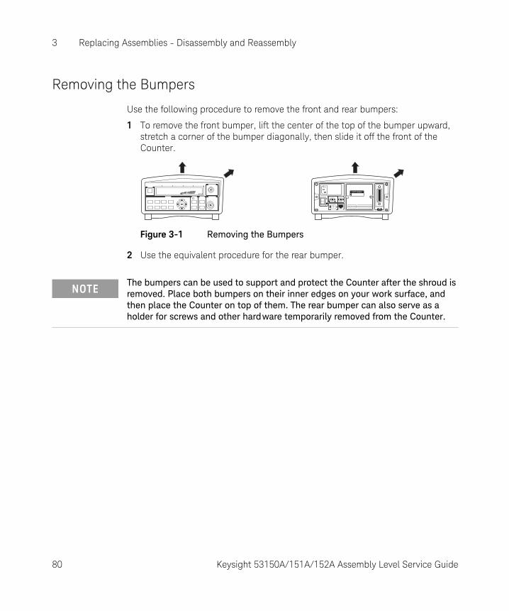
3 Replacing Assemblies - Disassembly and Reassembly
Removing the Bumpers
Use the following procedure to remove the front and rear bumpers:
1 To remove the front bumper, lift the center of the top of the bumper upward, stretch a corner of the bumper diagonally, then slide it off the front of the Counter.
Figure 3-1 Removing the Bumpers
2 Use the equivalent procedure for the rear bumper.
OPTIONS
NOTEThe bumpers can be used to support and protect the Counter after the shroud is removed. Place both bumpers on their inner edges on your work surface, and then place the Counter on top of them. The rear bumper can also serve as a holder for screws and other hardware temporarily removed from the Counter.
80 Keysight 53150A/151A/152A Assembly Level Service Guide
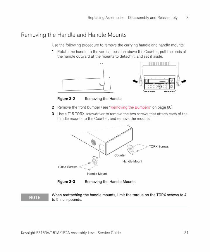
Replacing Assemblies - Disassembly and Reassembly 3
Removing the Handle and Handle Mounts
Use the following procedure to remove the carrying handle and handle mounts:
1 Rotate the handle to the vertical position above the Counter, pull the ends of the handle outward at the mounts to detach it, and set it aside.
Figure 3-2 Removing the Handle
2 Remove the front bumper (see “Removing the Bumpers” on page 80).
3 Use a T15 TORX screwdriver to remove the two screws that attach each of the handle mounts to the Counter, and remove the mounts.
Figure 3-3 Removing the Handle Mounts
TORX Screws
TORX Screws
Handle Mount
Handle Mount
Counter
NOTEWhen reattaching the handle mounts, limit the torque on the TORX screws to 4 to 5 inch-pounds.
Keysight 53150A/151A/152A Assembly Level Service Guide 81
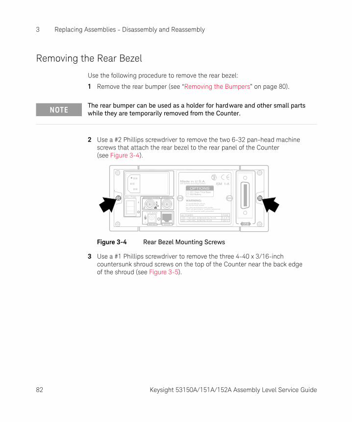
3 Replacing Assemblies - Disassembly and Reassembly
Removing the Rear Bezel
Use the following procedure to remove the rear bezel:
1 Remove the rear bumper (see “Removing the Bumpers” on page 80).
2 Use a #2 Phillips screwdriver to remove the two 6-32 pan-head machine screws that attach the rear bezel to the rear panel of the Counter (see Figure 3-4).
Figure 3-4 Rear Bezel Mounting Screws
3 Use a #1 Phillips screwdriver to remove the three 4-40 x 3/16-inch countersunk shroud screws on the top of the Counter near the back edge of the shroud (see Figure 3-5).
NOTEThe rear bumper can be used as a holder for hardware and other small parts while they are temporarily removed from the Counter.
WARNING:To avold electric shock,do not remove covers.
No user-serviceable parts inside.Refer all servicing to qualified personnel.
OPTIONS001 Oven Time Base002 Battery
This unit must be earth grounded.
Made in U.S.A.with domestic and foreign content
11 TO 18 VDC
EXT DC
Reference 10 MHz
InorOut
Auxillary
RS-232
Main ~ Power
100 – 130 VAC, 50/60/400 Hz 75 VA220 – 240 VAC, 50/60 Hz 75 VA 250 V
FUSE1.0 A T
AC POWER
ISM 1-A
82 Keysight 53150A/151A/152A Assembly Level Service Guide
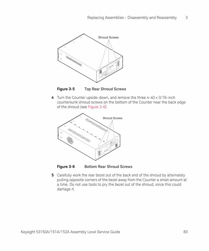
Replacing Assemblies - Disassembly and Reassembly 3
Figure 3-5 Top Rear Shroud Screws
4 Turn the Counter upside-down, and remove the three 4-40 x 3/16-inch countersunk shroud screws on the bottom of the Counter near the back edge of the shroud (see Figure 3-6).
Figure 3-6 Bottom Rear Shroud Screws
5 Carefully work the rear bezel out of the back end of the shroud by alternately pulling opposite corners of the bezel away from the Counter a small amount at a time. Do not use tools to pry the bezel out of the shroud, since this could damage it.
WARNING:
To avold electric shock,
do not remove covers.
No user-serviceable parts
inside.
Refer all s
ervicing to q
ualified personnel.
OPTIONS
001 Oven Time Base
002 Battery
This unit must b
e earth grounded.
Made in U
.S.A
.
with domestic and foreign content
AC POWER
100 – 130 VAC, 50/60/400 Hz
75 VA
220 – 240 VAC, 50/60 Hz
75 VA
250 V
FUSE
11 TO 18 VDC
EXT DC
Reference 10 MHz
InorOut
Auxillary
RS-232
Main ~ Power
1.0 A T
ISM 1-A
Shroud Screws
WARNING:
To avold electric shock,
do not remove covers.
No user-serviceable parts inside.
Refer all servicing to qualified personnel.
OPTIONS
001 Oven Time Base
002 Battery
This unit must be earth grounded.
Made in U.S.A.
with domestic and foreign content
AC POWER
100 – 130 VAC, 50/60/400 Hz 75 VA
220 – 240 VAC, 50/60 Hz 75 VA250 V
FUSE
11 TO 18 VDC
EXT DC
Reference 10 MHz
InorOut
Auxillary
RS-232
Main ~ Power
1.0 A T
ISM 1-A
Shroud Screws
Keysight 53150A/151A/152A Assembly Level Service Guide 83

3 Replacing Assemblies - Disassembly and Reassembly
Removing the Shroud
Use the following procedure to remove the shroud:
1 Remove the front and rear bumpers (see “Removing the Bumpers” on page 80).
2 Remove the handle and the handle mounts (see “Removing the Handle and Handle Mounts” on page 81).
3 Remove the rear bezel (see “Removing the Rear Bezel” on page 82).
4 Use a #1 Phillips screwdriver to remove the three 4-40 x 3/16-inch countersunk shroud screws from the top of the Counter near the front edge of the shroud (see Figure 3-7).
WARNINGWHEN THE SHROUD IS REMOVED FROM THE COUNTER, DANGEROUS LINE VOLTAGES THAT CAN CAUSE SERIOUS INJURY ARE EXPOSED. ALWAYS DISCONNECT THE POWER CORD BEFORE REMOVING THE SHROUD.
NOTEThe bumpers can be used to support and protect the Counter after the shroud is removed. Place both bumpers on their inner edges on your work surface, and then place the Counter on top of them. The rear bumper can also serve as a holder for screws and other hardware temporarily removed from the Counter.
84 Keysight 53150A/151A/152A Assembly Level Service Guide
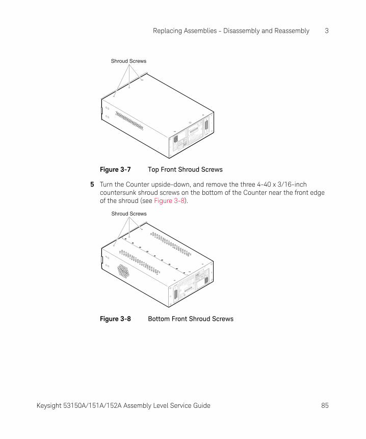
Replacing Assemblies - Disassembly and Reassembly 3
Figure 3-7 Top Front Shroud Screws
5 Turn the Counter upside-down, and remove the three 4-40 x 3/16-inch countersunk shroud screws on the bottom of the Counter near the front edge of the shroud (see Figure 3-8).
Figure 3-8 Bottom Front Shroud Screws
WARNING:
To avold electric shock,
do not remove covers.
No user-serviceable parts
inside.
Refer all s
ervicing to q
ualified personnel.
OPTIONS
001 Oven Time Base
002 Battery
This unit must b
e earth grounded.
Made in U
.S.A
.
with domestic and foreign content
AC POWER
100 – 130 VAC, 50/60/400 Hz
75 VA
220 – 240 VAC, 50/60 Hz
75 VA
250 V
FUSE
11 TO 18 VDC
EXT DC
Reference 10 MHz
InorOut
Auxillary
RS-232
Main ~ Power
1.0 A T
ISM 1-A
Shroud Screws
WARNING:
To avold electric shock,
do not remove covers.
No user-serviceable parts inside.
Refer all servicing to qualified personnel.
OPTIONS
001 Oven Time Base
002 Battery
This unit must be earth grounded.
Made in U.S.A.
with domestic and foreign content
AC POWER
100 – 130 VAC, 50/60/400 Hz 75 VA
220 – 240 VAC, 50/60 Hz 75 VA250 V
FUSE
11 TO 18 VDC
EXT DC
Reference 10 MHz
InorOut
Auxillary
RS-232
Main ~ Power
1.0 A T
ISM 1-A
Shroud Screws
Keysight 53150A/151A/152A Assembly Level Service Guide 85

3 Replacing Assemblies - Disassembly and Reassembly
6 With the Counter resting upside-down on your work surface, grip the front edge of the shroud in the cutout of the front bezel with the fingers of one hand, and push the Counter’s rear panel toward the front of the shroud with your other hand. Reduce the amount of pressure you apply to the rear panel when the shroud begins to slide off the Counter, and carefully remove the shroud the rest of the way (see Figure 3-9).
Figure 3-9 Removing the ShroudWARNING:
To avold electric shock,
do not remove covers.
No user-serviceable parts inside.
Refer all servicing to qualified personnel.
OPTIONS
001 Oven Time Base
002 Battery
This unit must be earth grounded.
Made in U.S.A.
with domestic and foreign content
AC POWER
100 – 130 VAC, 50/60/400 Hz 75 VA
220 – 240 VAC, 50/60 Hz 75 VA250 V250 V
FUSE
11 TO 18 VDC
EXT DCEXT DC
Reference 10 MHz
InorOut
Auxillary
RS-232
RS-232
Main ~ Power
1.0 A T1.0 A T
ISM 1-A
86 Keysight 53150A/151A/152A Assembly Level Service Guide

Replacing Assemblies - Disassembly and Reassembly 3
Removing the Front Bezel
Use the following procedure to remove the front bezel:
1 Remove the shroud hardware and slide the shroud back far enough to fully expose the front bezel, or remove the shroud completely (see “Removing the Shroud” on page 84).
2 Remove the four 4-40 x 3/16-inch self-locking flathead machine screws that attach the front bezel to the front panel (two on top and two on the bottom as shown in Figure 3-10).
Figure 3-10 Front Bezel Screws
3 Carefully slide the front bezel off the front panel.
FrontBezel
Screws
FrontBezelScrews
CAUTIONWhen reattaching the front bezel to the front-panel assembly, do not tighten the screws excessively to prevent damage to the bezel.
Keysight 53150A/151A/152A Assembly Level Service Guide 87
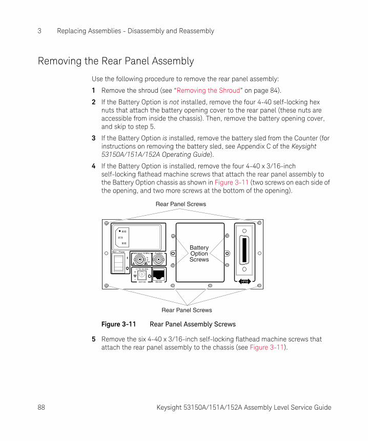
3 Replacing Assemblies - Disassembly and Reassembly
Removing the Rear Panel Assembly
Use the following procedure to remove the rear panel assembly:
1 Remove the shroud (see “Removing the Shroud” on page 84).
2 If the Battery Option is not installed, remove the four 4-40 self-locking hex nuts that attach the battery opening cover to the rear panel (these nuts are accessible from inside the chassis). Then, remove the battery opening cover, and skip to step 5.
3 If the Battery Option is installed, remove the battery sled from the Counter (for instructions on removing the battery sled, see Appendix C of the Keysight 53150A/151A/152A Operating Guide).
4 If the Battery Option is installed, remove the four 4-40 x 3/16-inch self-locking flathead machine screws that attach the rear panel assembly to the Battery Option chassis as shown in Figure 3-11 (two screws on each side of the opening, and two more screws at the bottom of the opening).
Figure 3-11 Rear Panel Assembly Screws
5 Remove the six 4-40 x 3/16-inch self-locking flathead machine screws that attach the rear panel assembly to the chassis (see Figure 3-11).
11 TO 18 VDC
EXT DC
Reference 10 MHz
InorOut
Auxillary
RS-232
Main ~ Power
Rear Panel Screws
Rear Panel Screws
BatteryOptionScrews
88 Keysight 53150A/151A/152A Assembly Level Service Guide
Replacing Assemblies - Disassembly and Reassembly 3
6 Disconnect the seven-wire cable that runs between the connector at the back end of the power supply (TB2) and connector PMAIN1 on the main board to provide better access to the cables that are attached to the back panel assembly.
7 Disconnect the GPIB ribbon cable from connector JP3 on the main board, and disengage the ribbon cable from the ribbon-cable clamps that are attached to the power supply and the inside of the left wall of the chassis. Position this cable so that it cannot catch on any other cables or other components of the Counter.
8 Disconnect the external-reference input/output cable (coaxial) from connector J8 on the main board. J8 is directly under the back edge of the power supply near the chassis wall.
9 A two-wire AC-input cable (brown and blue wires) runs between the Main ~ Power switch on the rear-panel assembly and the connector that is accessible through the cutout in the right-front corner of the power supply enclosure (TB1). Disconnect this cable from the power supply.
10 If the Battery Option is installed, there is a two-wire cable (brown and white wires) that runs between the Main ~ Power switch on the rear panel assembly and connector J3 on the Battery Option circuit board (J3 is the third connector from the back edge of the board). Disconnect this cable from J3 on the Battery Option circuit board.
NOTEThe screw in the lower-left corner of the rear panel assembly (as viewed from the rear of the Counter) may be covered by the serial-number sticker. If it is, carefully cut away the lower-left corner of the sticker to expose the screw head.
NOTEWhen reinstalling the Rear Panel Assembly, be sure to route the two-wire AC-input cable (brown and blue wires) underneath the power supply.
Keysight 53150A/151A/152A Assembly Level Service Guide 89

3 Replacing Assemblies - Disassembly and Reassembly
11 Use a 5/16-inch spin tight to remove the self-locking hex nut that attaches the rear panel assembly grounding wire (green/yellow) to the right wall of the chassis. Slide the grounding lug off the welded stud on the chassis wall, and thread the lock nut back onto the stud a few turns until it is finger-tight.
12 Extract the ends of all of the cables that you disconnected in Steps 7 through 9 from under the power supply, so that they are completely exposed and cannot catch on other cables and components when you remove the rear panel assembly.
13 Carefully pull the rear panel assembly away from the back end of the chassis. Guide the cables that remain attached to the rear panel assembly as you remove it to prevent them from catching on other cables or other components of the Counter.
WARNINGAN ELECTRICAL SHOCK HAZARD EXISTS IF THE COUNTER IS OPERATED WITH THE REAR PANEL ASSEMBLY GROUNDING WIRE NOT PROPERLY CONNECTED TO THE CHASSIS. TO PREVENT SERIOUS INJURY AND/OR DAMAGE TO THE EQUIPMENT, NEVER OPERATE THE COUNTER UNLESS THIS GROUND WIRE IS SECURELY CONNECTED TO THE CHASSIS WALL AND THE REAR PANEL ASSEMBLY.
CAUTIONWhen reinstalling the Rear Panel Assembly, position it carefully to avoid damage to the power LED, the serial-port connector (RJ-12), and the main board. If these components are not correctly aligned with the openings in the back panel, they may be damaged.
90 Keysight 53150A/151A/152A Assembly Level Service Guide
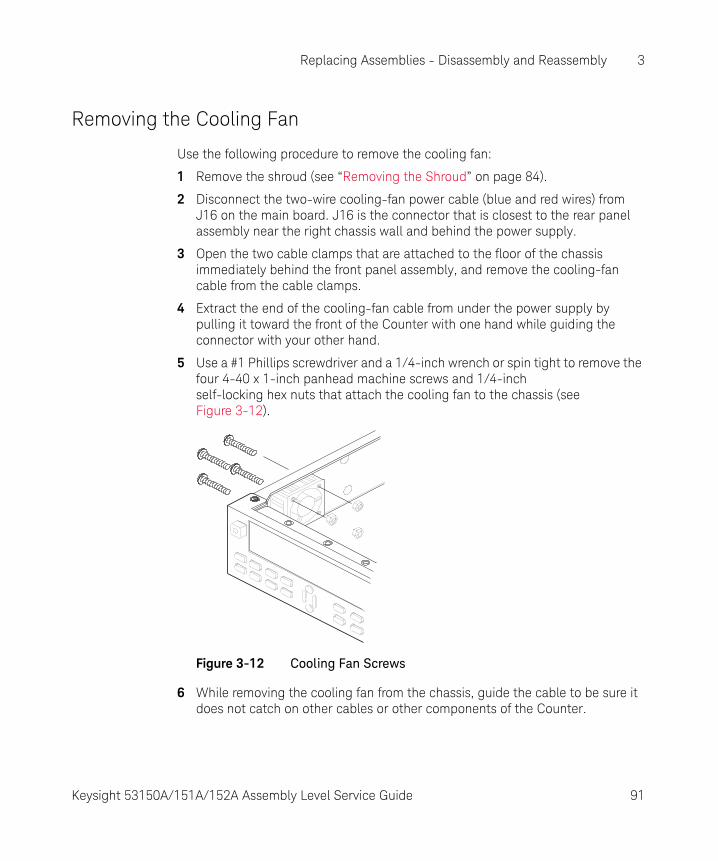
Replacing Assemblies - Disassembly and Reassembly 3
Removing the Cooling Fan
Use the following procedure to remove the cooling fan:
1 Remove the shroud (see “Removing the Shroud” on page 84).
2 Disconnect the two-wire cooling-fan power cable (blue and red wires) from J16 on the main board. J16 is the connector that is closest to the rear panel assembly near the right chassis wall and behind the power supply.
3 Open the two cable clamps that are attached to the floor of the chassis immediately behind the front panel assembly, and remove the cooling-fan cable from the cable clamps.
4 Extract the end of the cooling-fan cable from under the power supply by pulling it toward the front of the Counter with one hand while guiding the connector with your other hand.
5 Use a #1 Phillips screwdriver and a 1/4-inch wrench or spin tight to remove the four 4-40 x 1-inch panhead machine screws and 1/4-inch self-locking hex nuts that attach the cooling fan to the chassis (see Figure 3-12).
Figure 3-12 Cooling Fan Screws
6 While removing the cooling fan from the chassis, guide the cable to be sure it does not catch on other cables or other components of the Counter.
Keysight 53150A/151A/152A Assembly Level Service Guide 91
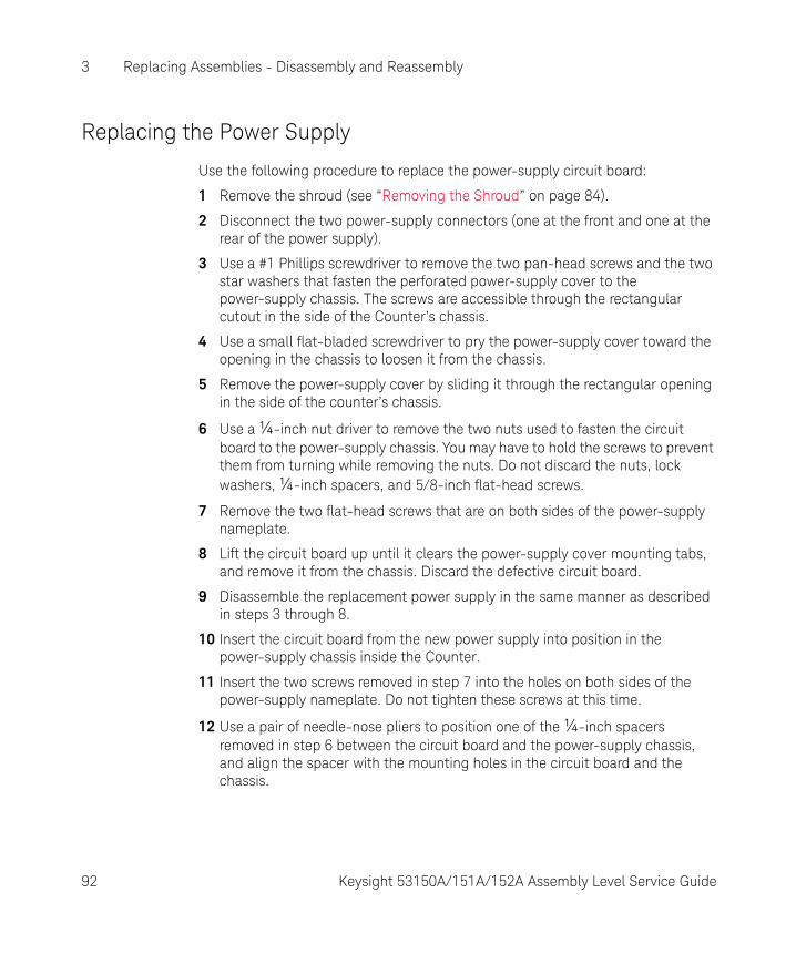
3 Replacing Assemblies - Disassembly and Reassembly
Replacing the Power Supply
Use the following procedure to replace the power-supply circuit board:
1 Remove the shroud (see “Removing the Shroud” on page 84).
2 Disconnect the two power-supply connectors (one at the front and one at the rear of the power supply).
3 Use a #1 Phillips screwdriver to remove the two pan-head screws and the two star washers that fasten the perforated power-supply cover to the power-supply chassis. The screws are accessible through the rectangular cutout in the side of the Counter’s chassis.
4 Use a small flat-bladed screwdriver to pry the power-supply cover toward the opening in the chassis to loosen it from the chassis.
5 Remove the power-supply cover by sliding it through the rectangular opening in the side of the counter’s chassis.
6 Use a ¼-inch nut driver to remove the two nuts used to fasten the circuit board to the power-supply chassis. You may have to hold the screws to prevent them from turning while removing the nuts. Do not discard the nuts, lock washers, ¼-inch spacers, and 5/8-inch flat-head screws.
7 Remove the two flat-head screws that are on both sides of the power-supply nameplate.
8 Lift the circuit board up until it clears the power-supply cover mounting tabs, and remove it from the chassis. Discard the defective circuit board.
9 Disassemble the replacement power supply in the same manner as described in steps 3 through 8.
10 Insert the circuit board from the new power supply into position in the power-supply chassis inside the Counter.
11 Insert the two screws removed in step 7 into the holes on both sides of the power-supply nameplate. Do not tighten these screws at this time.
12 Use a pair of needle-nose pliers to position one of the ¼-inch spacers removed in step 6 between the circuit board and the power-supply chassis, and align the spacer with the mounting holes in the circuit board and the chassis.
92 Keysight 53150A/151A/152A Assembly Level Service Guide

Replacing Assemblies - Disassembly and Reassembly 3
13 Insert one of the 5/8-inch, flat-head screws removed in step 6 up through the circuit-board mounting hole in the bottom of the power-supply chassis, through the spacer, and through the hole in the circuit board.
14 Place a lockwasher over the screw on top of the circuit board.
15 Thread a nut onto the screw, but do not tighten it fully at this time.
16 Repeat steps 12 through 15 for the other circuit-board mounting hole.
17 Tighten the two screws next to the power-supply nameplate.
18 Tighten the nuts on the circuit-board mounting screws.
19 Insert the power-supply cover through the rectangular hole in the side of the counter’s chassis, and position in properly on the power-supply.
20 Insert the two screws that fasten the power-supply cover to the chassis and tighten them.
21 Reconnect the two power-supply connectors and the front and rear ends of the power supply.
22 Turn the Counter on, and perform the “Power Supply Check” procedure on page 70.
23 If necessary, adjust the +5 VDC output of the power supply using the procedure titled “Adjusting the +5 VDC Output” on page 71.
24 Reassemble the Counter.
Keysight 53150A/151A/152A Assembly Level Service Guide 93

3 Replacing Assemblies - Disassembly and Reassembly
THIS PAGE HAS BEEN INTENTIONALLY LEFT BLANK.
94 Keysight 53150A/151A/152A Assembly Level Service Guide

Keysight 53150A/151A/152A Microwave Frequency CounterAssembly Level Service Guide
4 Replaceable Parts
Introduction 96Replaceable Parts 97How To Order A Part 98Parts Identification 100
95
4 Replaceable Parts
Introduction
This chapter contains parts-ordering information for the Keysight 53150A/151A/152A Counter. Table 4-1 lists the reference designations used in the parts list and throughout this guide, Table 4-2 lists all replaceable assemblies and parts. Figure 4-1 is an exploded view of the Keysight 53150A/151A/152A’s internal parts, Figure 4-2 is an exploded view of the cabinet and other external parts, and Figure 4-3 is a top view of the chassis with the shroud removed. These illustrations are provided to help you locate and identify parts.
96 Keysight 53150A/151A/152A Assembly Level Service Guide
Replaceable Parts 4
Replaceable Parts
Table 4-2 contains a list of replaceable parts that is organized as follows:
1 Electrical assemblies in alphanumeric order by reference designation.
2 Chassis-mounted electrical parts in alphanumeric order by reference designation.
3 Chassis-mounted mechanical parts in alphanumeric order by reference designation.
The information given for each part consists of the following:
1 Reference designation.
2 Keysight part number.
3 The quantity (QTY) of the part used in the instrument (field-replaceable items only).
4 Description of the part.
5 Typical manufacturer's part number for the part (when available).
Keysight 53150A/151A/152A Assembly Level Service Guide 97

4 Replaceable Parts
How To Order A Part
Keysight Technologies wants to keep your parts ordering process as simple and efficient as possible. To order parts, perform the following steps:
1 Identify the part and the quantity you need.
2 Determine the ordering method to be used, and contact Keysight.
If the part you need is not identified in the guide, you can call Keysight for assistance (see the following section titled Contacting Keysight Technologies). Please have the following information available when you contact Keysight:
– Instrument Model Number (example, “Keysight 53151A”).
– Complete instrument Serial Number (example, “1234A56789”). Information about where to find the serial number is provided in the Preface portion of this guide in the section titled How to Use This Guide.
– Description of the part(s) and its use.
– Quantity of the part(s) required.
98 Keysight 53150A/151A/152A Assembly Level Service Guide

Replaceable Parts 4
Contacting Keysight Technologies
Depending on where you are in the world, there are one or more ways to obtain parts or parts information from Keysight Technologies.
– Outside the United States, contact your local Keysight Technologies sales office.
– Within the United States, we encourage you to order replacement parts or request parts information directly by telephone or mail from Keysight using the telephone numbers or address listed on the next page. (You can also contact your local Keysight sales office. Keysight sales offices are listed in “Sales and Technical Support” on page 7.)
By Telephone:
– For Parts Ordering, use our toll-free number, (800) 227-8164, Monday through Friday (except Holidays), 6 a.m. to 5 p.m. (Pacific Time).
– For Parts Identification Assistance, call us at (916) 783-0804. Our Parts Identification hours are from 6 a.m. to 3 p.m. (Pacific Time) on Monday through Thursday and from 6 a.m. to 2 p.m. (Pacific Time) on Friday.
For Mail Correspondence, please use the address below:
Keysight TechnologiesP.O. Box 1145Roseville, CA 95661-1145
Keysight 53150A/151A/152A Assembly Level Service Guide 99

4 Replaceable Parts
Parts Identification
To identify the part(s) you need, refer to the exploded views in Figure 4-1 and Figure 4-2 and the top view of the chassis in Figure 4-3.
When ordering from Keysight Technologies, the important numbers to note from the Parts List are the Keysight Part Number, the part-number check digit (in the “CD” column), and the quantity of the part(s) you need.
Reference Designations
Table 4-1 lists the reference designations used in the parts lists.
Cabinet Parts and Hardware
To locate and identify cabinet and external parts and mounting hardware, refer to Figure 4-2 (internal parts and mounting hardware are shown in Figure 4-1). These figures provide different views of the instrument, with the parts identified by reference designations; the reference designations correspond with the ones in Table 4-2.
Accessories and Miscellaneous Items
Table 4-3 lists all of the accessories available for the Counter and also lists some other miscellaneous items, such as power cords, rack mounts, and manuals.
Table 4-1 Reference Designations
AHJ
MPP
===
==
assemblyhardwareelectrical connector (stationary portion); jackmiscellaneous mechanical partelectrical connector(movable portion); plug
P/0STTPUW
======
part ofswitchtransformertest pointintegrated circuit; microcircuitcable; transmission path; wire
100 Keysight 53150A/151A/152A Assembly Level Service Guide

Replaceable Parts 4
Figure 4-1 Keysight 53150A/151A/152A Exploded View — Internal Parts
H3, H4
A5
H5
A6
H6
A7
A8
A10
W2
W3A1
A2A3H2
H3H4
H4
A9
MP1
A4
H2
H2
H2
H2
H2
W1
H9
H7
H5
H11H10
H13H10
H12
H10
H5
H5
H8
H5
A11
A12
Keysight 53150A/151A/152A Assembly Level Service Guide 101

4 Replaceable Parts
M
Figure 4-2 Keysight 53150A/151A/152A Exploded View — Cabinet and External Parts
MP8
MP7 H16
H16
H15
MP6
MP3
MP4
P2
H15
H15
H15
H14MP5
H14
H5
H5
MP5
102 Keysight 53150A/151A/152A Assembly Level Service Guide
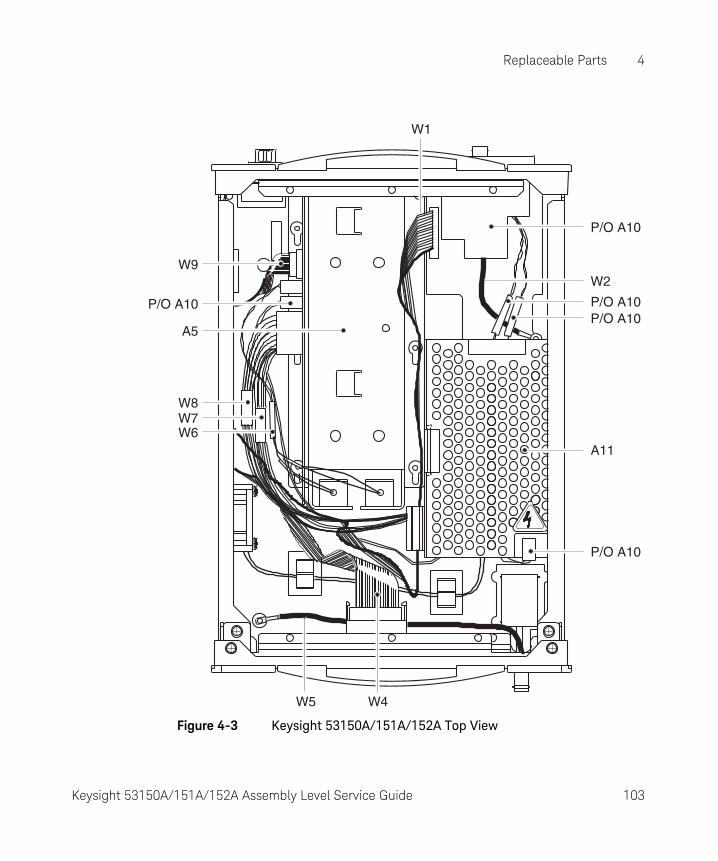
Replaceable Parts 4
Figure 4-3 Keysight 53150A/151A/152A Top View
W1
P/O A10
P/O A10
W2
P/O A10
P/O A10P/O A10
W8W7W6
W5 W4
W9
A5
A11
Keysight 53150A/151A/152A Assembly Level Service Guide 103
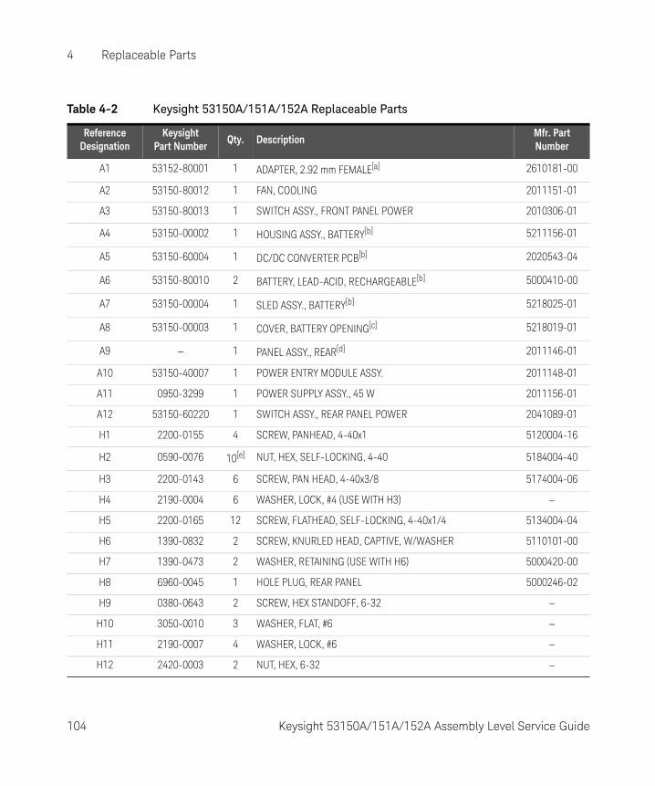
4 Replaceable Parts
Table 4-2 Keysight 53150A/151A/152A Replaceable Parts
Reference Designation
KeysightPart Number
Qty. DescriptionMfr. Part Number
A1 53152-80001 1 ADAPTER, 2.92 mm FEMALE[a] 2610181-00
A2 53150-80012 1 FAN, COOLING 2011151-01
A3 53150-80013 1 SWITCH ASSY., FRONT PANEL POWER 2010306-01
A4 53150-00002 1 HOUSING ASSY., BATTERY[b] 5211156-01
A5 53150-60004 1 DC/DC CONVERTER PCB[b] 2020543-04
A6 53150-80010 2 BATTERY, LEAD-ACID, RECHARGEABLE[b] 5000410-00
A7 53150-00004 1 SLED ASSY., BATTERY[b] 5218025-01
A8 53150-00003 1 COVER, BATTERY OPENING[c] 5218019-01
A9 — 1 PANEL ASSY., REAR[d] 2011146-01
A10 53150-40007 1 POWER ENTRY MODULE ASSY. 2011148-01
A11 0950-3299 1 POWER SUPPLY ASSY., 45 W 2011156-01
A12 53150-60220 1 SWITCH ASSY., REAR PANEL POWER 2041089-01
H1 2200-0155 4 SCREW, PANHEAD, 4-40x1 5120004-16
H2 0590-0076 10[e] NUT, HEX, SELF-LOCKING, 4-40 5184004-40
H3 2200-0143 6 SCREW, PAN HEAD, 4-40x3/8 5174004-06
H4 2190-0004 6 WASHER, LOCK, #4 (USE WITH H3) —
H5 2200-0165 12 SCREW, FLATHEAD, SELF-LOCKING, 4-40x1/4 5134004-04
H6 1390-0832 2 SCREW, KNURLED HEAD, CAPTIVE, W/WASHER 5110101-00
H7 1390-0473 2 WASHER, RETAINING (USE WITH H6) 5000420-00
H8 6960-0045 1 HOLE PLUG, REAR PANEL 5000246-02
H9 0380-0643 2 SCREW, HEX STANDOFF, 6-32 —
H10 3050-0010 3 WASHER, FLAT, #6 —
H11 2190-0007 4 WASHER, LOCK, #6 —
H12 2420-0003 2 NUT, HEX, 6-32 —
104 Keysight 53150A/151A/152A Assembly Level Service Guide
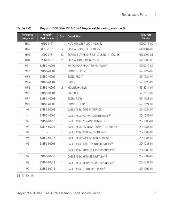
Replaceable Parts 4
H13 0590-0157 1 NUT, HEX, SELF-LOCKING, 6-32 5000046-00
H14 0515-1101 4 SCREW, TORX, FLATHEAD, m4x8 5138007-01
H15 2200-0164 12 SCREW, FLATHEAD, SELF-LOCKING, 4-40x3/16 5134004-03
H16 2360-0197 2 SCREW, PANHEAD, 6-32x3/8 5171006-06
MP1 53150-40008 1 SWITCH CAP, FRONT PANEL POWER 5230012-00
MP2 53150-40001 1 BUMPER, FRONT 5211122-01
MP3 53150-40009 1 BEZEL, FRONT 5211124-01
MP4 53150-40004 1 HANDLE 5211125-01
MP5 53150-40005 2 MOUNT, HANDLE 5218014-01
MP6 53150-00001 1 SHROUD 5218018-01
MP7 53150-40003 1 BEZEL, REAR 5211123-01
MP8 53150-40002 1 BUMPER, REAR 5211121-01
W1 53150-60209 1 CABLE ASSY., GPIB INTERFACE 2041084-01
— 53150-40006 1 CABLE ASSY., AC SWITCH INTERFACE[e] 2041089-01
W2 53150-60210 1 CABLE ASSY., COAXIAL, 10 MHz I/O 2041086-02
W3 53147-60224 1 CABLE ASSY, HARNESS, OUTPUT, DC SUPPLY 2041083-01
W4 — 1 CABLE ASSY, RIBBON, FRONT PANEL 2041085-01
W5 53150-60216 1 CABLE ASSY, COAXIAL, BAND 1 INPUT 2041086-01
W6 53150-60208 1 CABLE ASSY., BATTERY INTERCONNECT[f] 2041088-01
— — CABLE ASSY., HARNESS, INTERCONNECT[g] 2041082-01
W7 53150-60212 1 CABLE ASSY., HARNESS, RETURN[b] 2041087-02
W8 53150-60211 1 CABLE ASSY., HARNESS, INTERCONNECT[b] 2041087-01
W9 53150-60213 1 CABLE ASSY., STATUS INTERFACE[b] 2041092-01
[a] 53152A only
Table 4-2 Keysight 53150A/151A/152A Replaceable Parts (continued)
Reference Designation
KeysightPart Number
Qty. DescriptionMfr. Part Number
Keysight 53150A/151A/152A Assembly Level Service Guide 105

4 Replaceable Parts
[b] With Option 002 only
[c] Without Option 002
[d] Includes Rear Panel, Power Entry Module, GPIB Cable, 10 MHz I/O Cable, Power Switch, Hole Plug, and Fuse.
[e] Qty. = 8 without Option 002
[f] Part of A8
[g] In Counters without Option 002, this harness is used in place of W7 and W8.
Table 4-3 Keysight 53150A/151A/152A Accessories and Miscellaneous Items
Description Keysight Part Number
BATTERY 12 V 53150-80010
CABLE ASSY., EXT. DC POWER 53150-60214
CABLE ASSY., POWER (AUSTRALIA) 8120-0696
CABLE ASSY., POWER (CANADA) 8120-1692
CABLE ASSY., POWER (DENMARK) 8120-2957
CABLE ASSY., POWER (ENGLAND) 8120-1703
CABLE ASSY., POWER (GERMANY) 8120-2296
CABLE ASSY., POWER (JAPAN) 8120-4754
CABLE ASSY., POWER (S. AFRICA) 8120-4600
CABLE ASSY., POWER (USA) 8120-1521
CABLE ASSY., RS-232, DB-25/RJ-12 53150-60215
CARRYING CASE, SOFT 53150-80016
FUSE 2110-0007
GUIDE, OPERATING 53150-90001
GUIDE, PROGRAMMING 53150-90002
GUIDE, SERVICE 53150-90003
GPIB CABLES 10833A/B/C/D
RACK MOUNT, SINGLE 53150-67001
106 Keysight 53150A/151A/152A Assembly Level Service Guide

Keysight 53150A/151A/152A Microwave Frequency CounterAssembly Level Service Guide
5 Backdating
Introduction 108
107

5 Backdating
Introduction
As of the third edition of this guide, this chapter does not contain any information for adapting this guide to apply to older instruments.
As engineering changes are made, newer instruments may have higher serial prefix numbers than the ones shown on the title page of this guide. These instruments may be supplied with a Manual Updating Changes package containing the required information, or they may be supplied with newer editions of this guide that contain information about adapting that edition of this guide to older instruments.
If a Manual Updating Changes package is included with your Counter, modify existing guide information or replace the affected pages as directed in the pages of the Manual Updating Changes package. For additional information, contact the nearest Keysight Sales and Support Office.
108 Keysight 53150A/151A/152A Assembly Level Service Guide

Keysight 53150A/151A/152A Microwave Frequency CounterAssembly Level Service Guide
6 Specifications
For the specifications and characteristics of the 53150A/151A/152A Microwave Frequency Counter, refer to the datasheet at http://literature.cdn.keysight.com/litweb/pdf/5966-3118E.pdf
109

6 Specifications
THIS PAGE HAS BEEN INTENTIONALLY LEFT BLANK.
110 Keysight 53150A/151A/152A Assembly Level Service Guide

Index
Symbols+5 VDC, 71
Numerics1 MHz External Timebase Input, 32, 36, 3822 GHz to 26.5 GHz Frequency Sensitivity, 4730 GHz to 46 GHz Frequency Sensitivity, 4850 MHz to 125 MHz Frequency Sensitivity, 4250 MHz to 20 GHz Frequency Sensitivity, 4550 MHz to 20 GHz Power Measure-ment (–20 dBm), 49
AAccessories, 106
Available, 23Supplied, 23Supplied and Available, 23
Accessories and Miscellaneous Items, 100address, 99adjusting the +5 VDC output, 71Assemblies, 77assemblies, 78, 96Assembly Identification, 68Automotive Power Adapter, 23
Bbattery, 23Battery Charger, 23Bumpers, 80
CCabinet, 102cabinet, 96Cabinet Parts and
Hardware, 100cables, 23calibration, 27, 63Calibration Procedure, 63calibration procedure, 63Case, 23Channel 1 Frequency Sensitivity, 36Channel 2 22 GHz to 26.5 GHz Power Measurement (0 dBm), 53Channel 2 22 GHz to 26.5 GHz Power Measurement (–20 dBm), 51Channel 2 26.5 GHz to 46 GHz Power Measurement (–20 dBm), 52Channel 2 30 GHz to 46 GHz Power Measurement (0 dBm), 53Channel 2 50 MHz to 20 GHz Power Measurement (0 dBm), 52Channel 2 Power Measurement, 49Complete Performance Tests, 26, 27, 35Contacting Keysight Technologies, 99Cooling Fan, 91correspondence, 99
DDC Power Supply Assembly, 70Description of the Counter, 21
Eelectrostatic discharge, 66Emergency Response, 61equipment, 66Equipment Required, 28Error Messages, 73, 74
–12V FAIL, 74, 7512V FAIL, 74, 75–5V FAIL, 74, 75ADC FAIL, 74, 75
EEP WRT FAIL, 74FPANEL FAIL, 74FPGA FAIL, 74, 75GPIB FAIL, 74HET PATH FAIL, 74HPIB FAIL, 75IIC FAIL, 74, 75INSTCFG FAIL, 74, 75OVERTEMP, 74PATH FAIL, 74PWR CAL FAIL, 74, 76PWR CKT FAIL, 74RAM FAIL, 74, 76SAV SET FAIL, 75, 76SERVICE FAIL, 75, 76THRS FAIL, 74THRS HET, 74THRS THRU, 74THRU FAIL, 75VCO/CNT FAIL, 75
Exploded View, 101, 102exploded view, 96exploded views, 100Express Calibration Service, 18, 61external parts, 96External Timebase Tests, 36
Ffan, 29Frequency Sensitivity, 40, 42, 45, 47, 48, 54, 55Front Bezel, 87front bumper, 80Front Panel at a Glance, 26fuse, 23
GGPIB Cables, 23
HHandle, 81
Keysight 53150A/151A/152A Assembly Level Service Guide 111

Handle Mounts, 81How To Order A Part, 98
IInstrument Identification, 19Instrument Service Division, 61Internal Parts, 101internal parts, 96ISD, 61
MManual Updating Changes, 108Manuals
supplied, 23Manuals Supplied, 23Messages, 75messages, 73, 74Miscellaneous Items, 106
OOperational Verification, 26, 54Options, 22
Hardware, 22options, 22ordering parts, 98
PPacking the Counter in Commer-cially Available Packaging Materials, 62Packing the Counter in the Original Packaging Materials, 62Parts, 95, 101, 102, 104Parts Identification Assistance, 99Parts Ordering, 99parts ordering, 98parts-ordering information, 96Performance Test Record, 27, 54, 55performance test record, 54, 55, 56, 57Power Measurement, 49, 51, 52Power Supply Assembly, 70
RRack Mount Kit, 23Rear Bezel, 82rear bumper, 80Rear Panel Assembly, 88Recommended Calibration Cycle, 27Reference Designations, 100reference designations, 96Removing the Bumpers, 80Removing the Cooling Fan, 91Removing the Cover, 84Removing the Front Bezel, 87Removing the Handle and the Han-dle Mounts, 81Removing the Rear Bezel, 82Removing the Rear Panel Assembly, 88Removing the Shroud, 84repair, 18replaceable assemblies, 96Replaceable Parts, 95, 104replaceable parts, 97Replacing Assemblies, 77required equipment, 28Returning the Counter for Service, 61Returning the Counter to Keysight Technologies for Service, 61RS-232, 73, 74RS-232 Cable, 23
Ssafety, 65Self-Test, 72, 73Serial Number, 98serial number, 19service, 18, 59Shroud, 84Soft Carrying Case, 23specifications, 35Standby mode, 29support options, 22surface-mount components, 66
TTest 1
Channel 1 Frequency Sensitivity, 36
Test 1a10 Hz to 20 MHz Frequency Sensitivity, 40
Test 1b50 MHz to 125 MHz Frequency Sensitivity, 42
Test 2Channel 2 Frequency Sensitivity, 45
Test 2a50 MHz to 20 GHz Frequency Sensitivity, 45
Test 2b22 GHz to 26.5 GHz Frequency Sensitivity, 47
Test 2c30 GHz to 46 GHz Frequency Sensitivity, 48
Test 3Channel 2 Power Measurement, 49
Test 3bChannel 2 22 GHz to 26.5 GHz Power Measurement (–20 dBm), 51
Test 3cChannel 2 26.5 GHz to 46 GHz Power Measurement (–20 dBm), 52
Test 3dChannel 2 50 MHz to 20 GHz Power Measurement (0 dBm), 52
Test 3eChannel 2 22 GHz to 26.5 GHz Power Measurement (0 dBm), 53
Test 3fChannel 2 30 GHz to 46 GHz Power Measurement (0 dBm), 53
test equipment, 66test record, 54, 55, 56, 57
112 Keysight 53150A/151A/152A Assembly Level Service Guide
timebase, 29toll-free number, 99Tools, 79Tools Required, 79Top View, 103top view, 96troubleshooting, 65, 70Troubleshooting the Counter, 70
Wwarranty, 66
Keysight 53150A/151A/152A Assembly Level Service Guide 113

THIS PAGE HAS BEEN INTENTIONALLY LEFT BLANK.
114 Keysight 53150A/151A/152A Assembly Level Service Guide

This information is subject to change without notice. Always refer to the Keysight website for the latest revision.
© Keysight Technologies 1999 - 2017Edition 3, December 1, 2017
Printed in Malaysia
*53150-90015*53150-90015www.keysight.com