Keynote Published
20
Advances in engineered surfaces for functional performance A.A.G. Bruzzone (2) a, *, H.L. Costa b , P.M. Lonardo (1) a , D.A. Lucca (1) c a Dipartimento di Ingegneria della Produzione, Termoenergetica e Modelli Matematici, University of Genoa, Genoa, Italy b Laborato ´ rio de Tribologia e Materiais, Universidade Federal de Uberla ˆ ndia, Campus Santa Mo ˆ nica, Uberla ˆ ndia, Brazil c School of Mechanical and Aerospace Engineering, Oklahoma State University, Stillwater, USA 1. Introduction The most impo rtan t phys ical phen omen a invo lving exch ange of ener gy and/ or signa l transmission take plac e on surf aces. The advances in man y fields of sci ence over thelast century have taken place as a result of a deeper knowledge of how surfaces influence the mechanisms and kinetics of this energy and signal transfer. In thelast fewdecade s, theunder stan din g of sur fac e phe nomena , particularly at a micro- and nanometer scale, has played a funda- mental role in the development of many advanced fields, such as: elec tro nics, info rmation tec hno logy , ener gy, opt ics, trib olo gy, biology, biomimetics, etc. Furthermore, a rush towards miniatur- ization can be observed, with a vast technological advance in the are a of microfabri cat ion . The fun cti onal expl oitatio n of seve ral physical phenomena becomes more and more important with the reduction of dimensions. Since the availability of technologies that per mit themanufac tur e and con tro l of mic ro/ nan o-su rfa ce features is ano ther key issu e for min iatu riza tion , man y tec hni ques are curren tly available to crea te sur face featu res with sizes in the micromete r ran ge. The man ufa cturin g of feat ures on the nan ome ter sca le is more ch all en gin g, and ha s als o been the subje ct of int en siv e research and development. It has been nearly one decade since the last CIRP keynote paper [78] established the state of the art for structured, textured or engineered surfaces. The relationships between the technologies for struc turin g sur fac es, their fun ction al pro per ties and the appl ications explo itin g the surfa ce fun ctio nalit y are a common denominator of the research carried out in the last years. Since then the aspe cts rela ting surfaces to prod uct ion [44,91] , metr olog y [55,62,108,155] , emerging applications [61] and chemical inter- actions [29] have been analysed. The relationships between the domains of applications, func- tional properties and engineering technologies are rather complex (Fig. 1). As the dimension reduces, different surface phenomena and functional properties can be exploited in order to carry out the same app lication. On the other hand, an app lication can use different surface properties and, furthermo re, a specific functional property can be at the basis of different applications. For example, adhe sion is con trol led by surf ace wett abili ty (i.e. , free ener gy), roughness [20] and its interlocking properties. Considering the relationships between function al properties and engi neer ing tech nolo gies, the same technolo gy adop ted to engineer or structure surfaces can enhance or use different func- tional properties. Conversely, many functional properties can be the core of a specific technology. Moreover, different engineering technologies can exploit the same functional property. A clear distinction between the set of applications, functional pr ope rti es, and eng ine eri ng tec hn olo gies must be mad e in ord er to est abl ish a sou nd fra me wor k for the sci entifi c dev elo pme nt of new applications and/or processes. The desig n-manuf actu ring proc ess to impl ement an appl icat ion that exploits surf ace func tion al prop erties follows the sche ma represented in Fig. 2 [154]. The goal, i.e., the specific applicatio n, is achieved through the recognition of the functional property(ies) required by the surface. The task of the design phase consists of con ceiving a way to imple ment the requ ired functio n(s). The production step relies definitely on the development, or use, of techniques able to structure the surface(s), and these techniques depend essentially on specific functional properties of surfaces. The knowledge of physics, materials and processes is essential dur ing the design and produc tion steps of a ‘‘sur face -base d’’ application. Thi s paper wil l report the advancements con cerni ng the functional properties, applications and engineering technologies available to structure surfaces. CIRP Annals - Manufacturing Technology 57 (2008) 750–769 A R T I C L E I N F O Keywords: Surface Engineered surface Engineering technology A B S T R A C T Surface phenomena play a decisive role in the behaviour of engineering parts ; their unders tanding and control are fundamental to the development of many advanced fields, such as: electronics, information technol ogy, energy, optics , tribol ogy, biolog y and biomimetics. Engine ered surfaces rely on the contro l of surf ace char act eris tic s to obt ain a desi red func tional per for manc e. Thi s paper rep ortsthe advances in the state of the art considerin g the rel atio nshi ps between the pro per ties of functional sur faces, their applic ations and the technologies to engineer surfaces. ß 2008 CIRP. * Corresponding au thor. Contents lists available at ScienceDirect CIRP Annals - Manufacturing Technology journal homepage: http://ees.elsevier.com/cirp/default.asp 0007-8506/$ – see front matter ß 2008 CIRP. doi:10.1016/j.cirp.2008.09.003
-
Upload
rafaalmeida -
Category
Documents
-
view
220 -
download
0
Transcript of Keynote Published
7/22/2019 Keynote Published
http://slidepdf.com/reader/full/keynote-published 1/20
Advances in engineered surfaces for functional performance
A.A.G. Bruzzone (2)a,*, H.L. Costa b, P.M. Lonardo (1)a, D.A. Lucca (1)c
a Dipartimento di Ingegneria della Produzione, Termoenergetica e Modelli Matematici, University of Genoa, Genoa, Italyb Laborato rio de Tribologia e Materiais, Universidade Federal de Uberla ndia, Campus Santa Mo nica, Uberla ndia, Brazilc School of Mechanical and Aerospace Engineering, Oklahoma State University, Stillwater, USA
1. Introduction
The most important physical phenomena involving exchange of
energy and/or signal transmission take place on surfaces. The
advances in many fields of science over thelast century have takenplace as a result of a deeper knowledge of how surfaces influence
the mechanisms and kinetics of this energy and signal transfer.
In thelast fewdecades, theunderstanding of surface phenomena,
particularly at a micro- and nanometer scale, has played a funda-
mental role in the development of many advanced fields, such as:
electronics, information technology, energy, optics, tribology,
biology, biomimetics, etc. Furthermore, a rush towards miniatur-
ization can be observed, with a vast technological advance in the
area of microfabrication. The functional exploitation of several
physical phenomena becomes more and more important with the
reduction of dimensions. Since the availability of technologies that
permit the manufacture and control of micro/nano-surface features
is another key issue for miniaturization, many techniques are
currently available to create surface features with sizes in the
micrometer range. The manufacturing of features on the nanometer
scale is more challenging, and has also been the subject of intensive
research and development.
It has been nearly one decade since the last CIRP keynote paper
[78] established the state of the art for structured, textured or
engineered surfaces. The relationships between the technologies
for structuring surfaces, their functional properties and the
applications exploiting the surface functionality are a common
denominator of the research carried out in the last years. Since
then the aspects relating surfaces to production [44,91], metrology
[55,62,108,155], emerging applications [61] and chemical inter-
actions [29] have been analysed.
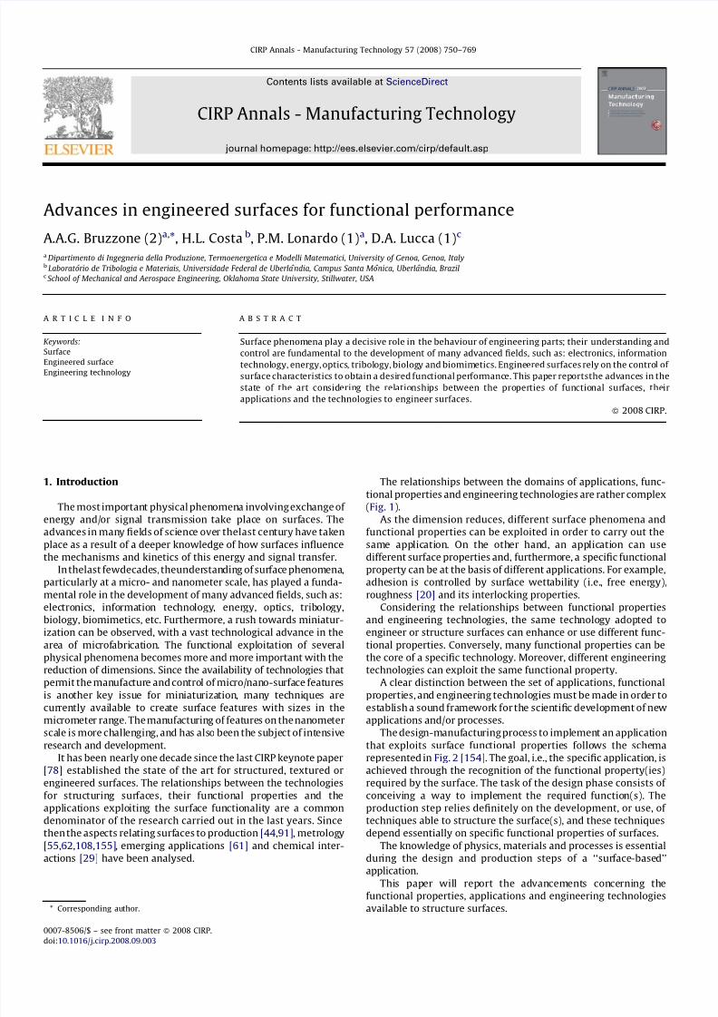
The relationships between the domains of applications, func-
tional properties and engineering technologies are rather complex
(Fig. 1).
As the dimension reduces, different surface phenomena and
functional properties can be exploited in order to carry out thesame application. On the other hand, an application can use
different surface properties and, furthermore, a specific functional
property can be at the basis of different applications. For example,
adhesion is controlled by surface wettability (i.e., free energy),
roughness [20] and its interlocking properties.
Considering the relationships between functional properties
and engineering technologies, the same technology adopted to
engineer or structure surfaces can enhance or use different func-
tional properties. Conversely, many functional properties can be
the core of a specific technology. Moreover, different engineering
technologies can exploit the same functional property.
A clear distinction between the set of applications, functional
properties, and engineering technologies must be made in order to
establish a sound framework for the scientific development of new
applications and/or processes.
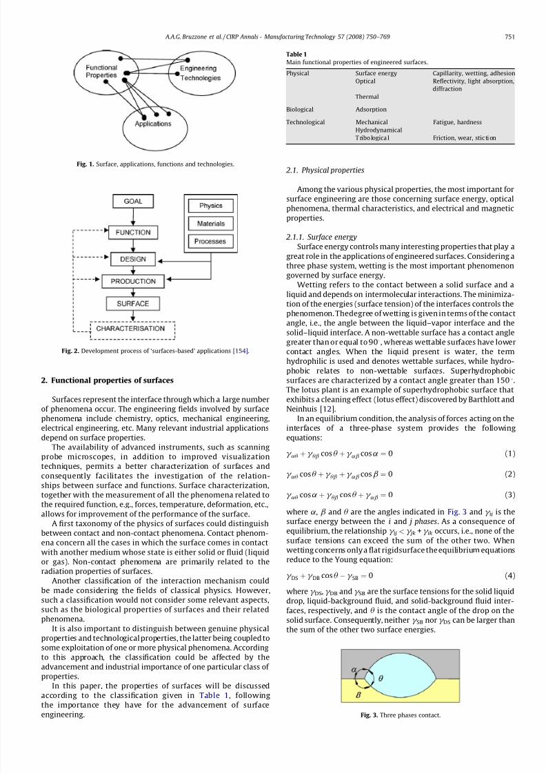
The design-manufacturing process to implement an application
that exploits surface functional properties follows the schema
represented in Fig. 2 [154]. The goal, i.e., the specific application, is
achieved through the recognition of the functional property(ies)
required by the surface. The task of the design phase consists of
conceiving a way to implement the required function(s). The
production step relies definitely on the development, or use, of
techniques able to structure the surface(s), and these techniques
depend essentially on specific functional properties of surfaces.
The knowledge of physics, materials and processes is essential
during the design and production steps of a ‘‘surface-based’’
application.
This paper will report the advancements concerning the
functional properties, applications and engineering technologiesavailable to structure surfaces.
CIRP Annals - Manufacturing Technology 57 (2008) 750–769
A R T I C L E I N F O
Keywords:
Surface
Engineered surface
Engineering technology
A B S T R A C T
Surface phenomena play a decisive role in the behaviour of engineering parts; their understanding and
control are fundamental to the development of many advanced fields, such as: electronics, informationtechnology, energy, optics, tribology, biology and biomimetics. Engineered surfaces rely on the control of
surface characteristics to obtain a desired functional performance. This paper reportsthe advances in the
state of the art considering the relationships between the properties of functional surfaces, their
applications and the technologies to engineer surfaces.
ß 2008 CIRP.
* Corresponding author.
Contents lists available at ScienceDirect
CIRP Annals - Manufacturing Technology
journal homepage: http://ees.elsevier.com/cirp/default.asp
0007-8506/$ – see front matterß 2008 CIRP.
doi:10.1016/j.cirp.2008.09.003
7/22/2019 Keynote Published
http://slidepdf.com/reader/full/keynote-published 2/20
2. Functional properties of surfaces
Surfaces represent the interface through which a large number
of phenomena occur. The engineering fields involved by surfacephenomena include chemistry, optics, mechanical engineering,
electrical engineering, etc. Many relevant industrial applications
depend on surface properties.
The availability of advanced instruments, such as scanning
probe microscopes, in addition to improved visualization
techniques, permits a better characterization of surfaces and
consequently facilitates the investigation of the relation-
ships between surface and functions. Surface characterization,
together with the measurement of all the phenomena related to
the required function, e.g., forces, temperature, deformation, etc.,
allows for improvement of the performance of the surface.
A first taxonomy of the physics of surfaces could distinguish
between contact and non-contact phenomena. Contact phenom-
ena concern all the cases in which the surface comes in contactwith another medium whose state is either solid or fluid (liquid
or gas). Non-contact phenomena are primarily related to the
radiation properties of surfaces.
Another classification of the interaction mechanism could
be made considering the fields of classical physics. However,
such a classification would not consider some relevant aspects,
such as the biological properties of surfaces and their related
phenomena.
It is also important to distinguish between genuine physical
properties and technological properties, the latter being coupled to
some exploitation of one or more physical phenomena. According
to this approach, the classification could be affected by the
advancement and industrial importance of one particular class of
properties.In this paper, the properties of surfaces will be discussed
according to the classification given in Table 1, following
the importance they have for the advancement of surface
engineering.
2.1. Physical properties
Among the various physical properties, the most important for
surface engineering are those concerning surface energy, optical
phenomena, thermal characteristics, and electrical and magnetic
properties.
2.1.1. Surface energy
Surface energy controls many interesting properties that play a
great role in the applications of engineered surfaces. Considering a
three phase system, wetting is the most important phenomenon
governed by surface energy.
Wetting refers to the contact between a solid surface and a
liquid and depends on intermolecular interactions. The minimiza-
tion of the energies (surface tension) of the interfaces controls the
phenomenon. Thedegree of wetting is given in terms of the contact
angle, i.e., the angle between the liquid–vapor interface and the
solid–liquid interface. A non-wettable surface has a contact angle
greater than or equal to 908, whereas wettable surfaces have lower
contact angles. When the liquid present is water, the term
hydrophilic is used and denotes wettable surfaces, while hydro-
phobic relates to non-wettable surfaces. Superhydrophobic
surfaces are characterized by a contact angle greater than 1508.
The lotus plant is an example of superhydrophobic surface that
exhibits a cleaning effect (lotus effect) discovered by Barthlott and
Neinhuis [12].In an equilibrium condition, the analysis of forces acting on the
interfaces of a three-phase system provides the following
equations:
g au þ g ub cosu þ g ab cosa ¼ 0 (1)
g au cosu þ g ub þ g ab cosb ¼ 0 (2)
g au cosaþ g ub cosu þ g ab ¼ 0 (3)
where a, b and u are the angles indicated in Fig. 3 and g ij is the
surface energy between the i and j phases. As a consequence of
equilibrium, the relationship g ij < g jk + g ik occurs, i.e., none of the
surface tensions can exceed the sum of the other two. Whenwetting concerns only a flat rigidsurface the equilibrium equations
reduce to the Young equation:
g DS þ g DB cosu À g SB ¼ 0 (4)
where g DS, g DB and g SB are the surface tensions for the solid liquid
drop, liquid-background fluid, and solid-background fluid inter-
faces, respectively, and u is the contact angle of the drop on the
solid surface. Consequently, neither g SB nor g DS can be larger than
the sum of the other two surface energies.
Fig. 1. Surface, applications, functions and technologies.
Fig. 2. Development process of ‘surfaces-based’ applications [154].
Table 1
Main functional properties of engineered surfaces.
Physical Surface energy Capillarity, wetting, adhesion
Optical Reflectivity, light absorption,
diffraction
Thermal
Biological Adsorption
Technological Mechanical Fatigue, hardness
Hydrodynamical
T ribo logica l Friction, wear, stic ti on
Fig. 3. Three phases contact.
A.A.G. Bruzzone et al. / CIRP Annals - Manufacturing Technology 57 (2008) 750–769 751
7/22/2019 Keynote Published
http://slidepdf.com/reader/full/keynote-published 3/20
To measure wetting the spreading parameter S can be defined:
S ¼ g SB À ðg DS þ g DBÞ (5)
The liquid wets the surface completely when S > 0, and
incompletely when S < 0.
When the system is not in equilibrium, e.g., when a droplet
expands or retracts, different mechanics apply. Hysteresis in the
contact angle can be observed; the static contact angle after
expansion is higher than that observed after a contraction. In
dynamic conditions the contact line does not move regularly but
incrementally, apparently with a stick-slip mechanism. These
aspects of dynamic wetting are currently the subjects of research
by many scientists.
Wetting and de-wetting of structured and imprinted surfaces
has been theoretically studied by Lipowsky et al. [150]. A
theoretical study regarding the influence of surface roughness
on superhydrophobicity is reported in Ref. [246].
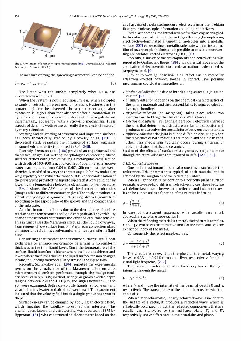
Recently, Seemann et al. [198] provided an experimental and
theoretical analysis of wetting morphologies considering silicon
surfaces etched with grooves having a rectangular cross section
with depth of 100–900 nm, and width of 400 nm–3 mm (groove
aspect ratio ranging from 0.04 to 0.60). Silicon substrates were
chemically modified to vary the contact angle u for low molecular
weight polystyrene withinthe range 5–808. Vapor condensation of
the polystyrene provided the liquid droplets that were solidified bylowering the temperature below the glass transition temperature.
Fig. 4 shows the AFM images of the droplet morphologies
(images refer to different contact angles). The study introduced a
global morphology diagram of clustering droplet geometries
according to the aspect ratio of the groove and the contact angle
of the substrate.
Another important effect is due to the dependence of surface
tension on the temperature and liquid composition. The variability
of one of these factors determines the variation of surface tension.
This in turn causes the Marangoni effect, i.e., the liquid flows away
from regions of low surface tension. Marangoni convection plays
an important role in hydrodynamics and heat transfer in fluid
films.
Considering heat transfer, the structured surfaces used in heatexchangers to enhance performance determine a non-uniform
thickness in the thin liquid layer. Since the temperature of the
surface–liquid interface is higher where the liquid is thinner and
lower where the film is thicker, the liquid surface tension changes
locally, influencing thermocapillary stresses and liquid flow.
Recently, Skornyakov et al. [204] reported the experimental
results on the visualization of the Marangoni effect on glass
microstructured surfaces performed through the background-
oriented Schlieren (BOS) method. Triangular grooves with a depth
ranging between 250 and 1000 mm, and angles between 608 and
908 were examined. Both non-volatile liquids (silicone oil) and
volatile liquids (water and alcohols) were used. The experiment
indicated that the velocity field inside a single groove has a vortex
shape.Surface energy can be changed by applying an electric field,
which modifies the capillary forces at the interface. This
phenomenon, known as electrowetting, was reported in 1875 by
Lippmann [151], who constructed an electrometer based on the
capillary rise of a polarizedmercury–electrolyte interface to obtain
first-grade microscopic information about liquid interfaces.
In the last decades, the introduction of surface engineering led
to the enhancement of the electrowetting effect, e.g.,by implanting
electroactive-terminated alkane-thiol molecules into a metallic
surface [207] or by coating a metallic substrate with an insulating
film of macroscopic thickness, it is possible to obtain electrowet-
ting on insulator-coated electrodes (EICE) [19].
Recently, a survey of the developments of electrowetting wasreported by Quilliet and Berge [189] and numerical models for the
application of electrowetting to droplet actuation are described by
Arzpeyma et al. [9].
Similar to wetting, adhesion is an effect due to molecular
attraction exerted between bodies in contact. Five possible
mechanisms could determine adhesion:
Mechanical adhesion: is due to interlocking as seen in joints on
Velcro1 [63]. Chemical adhesion: depends on the chemical characteristics of
the joining materials and their susceptibility to ionic, covalent or
hydrogen bonding. Dispersive adhesion (or adsorption): takes place when two
materials are held together by van der Waals forces. Electrostatic adhesion: relies on a difference in electrical charge at
the joint that determines a structure similar to a capacitor and
produces an attractive electrostatic force between the materials. Diffusive adhesion: the joint is due to diffusion occurring when
the molecules of both materials are mobile and soluble in each
other. This mechanism typically occurs during sintering of
polymer chains, metals and ceramics.
Studies of the effects of surface micro-geometry on joints made
through structural adhesives are reported in Refs. [32,42,153].
2.1.2. Optical properties
One of the most important optical properties of surfaces is the
reflectance. This parameter is typical of each material and is
affected by the roughness of the reflecting surface.
When a light beam is incident onto a perfectly planar surfaceseparating two media of differentrefractive indices, the reflectance
r is defined as the ratio between the reflected and incident fluxes.
It can be expressed as a function of the relative index n:
r ¼ n À 1
n þ 1
2
(6)
In case of transparent materials, r is usually very small,
approaching zero as n approaches 1.
When the reflecting material is a metal, the index n is complex,
n = nÀ jx, where n is the refractive index of the metal and x is the
extinction index of the metal.
Consequently the reflectance becomes:
r ¼ ðnÀ 1Þ2 þ x2
ðnþ 1Þ2 þ x2(7)
The r value is relevant for the gloss of the metal, varying
between 0.33 and 0.94 for iron and silver, respectively, for a mid
visual light frequency [237].
The extinction index establishes the decay law of the light
intensity through the metal:
I z ¼ I 0 eÀð4px=lÞ z (8)
where I 0 and I z are the intensity of the beam at depths 0 and z ,
respectively. The transparency of the material decreases with the
value of x.
When a monochromatic, linearly polarized wave is incident tothe surface of a metal, it produces a reflected wave, which is
elliptically polarized. In fact, the reflected components that are
parallel and transverse to the incidence plane, E 00p and E 00t ,
respectively, show differences in their modulus and phase.
Fig. 4. AFM images of droplet morphologies (source [198], Copyright 2005 National
Academy of Sciences, U.S.A.).
A.A.G. Bruzzone et al. / CIRP Annals - Manufacturing Technology 57 (2008) 750–769752
7/22/2019 Keynote Published
http://slidepdf.com/reader/full/keynote-published 4/20
The relationships between the reflected components and the
incident components, E p and E t, are given by the Fresnel formulae:
E 00p ¼ E pn cosu À cosu
0
n cosu þ cosu 0 ; E 00t ¼ E t
cosu À n cosu 0
n cosu þ n cosu 0 (9)
The influence of roughness on the surface reflectance has been
extensively studied.
A classic study by Bennet and Porteus [17] established that for a
normal incidence and a Gaussian distribution of the topographyheights, the relationship between the reflectance r of a rough
surface and the reflectance r0 of a smooth surface of the same
material is
r
r0
¼ eÀð4pRqlÞ
2
þ 32p4 Rq
l
4e
2Rdq
2
(10)
where l is the light wavelength and e is the aperture angle of the
receiving optical system. The first term of theequation refers to the
specular reflection and the second term to the contribution of the
diffuse reflection in the normal direction. For small values of the
ratio Rq/l, the reflectance canbe assumed dependentonly upon Rq.
Based on this principle, optical instruments measuring the
roughness through the measurement of reflectance have been
proposed.Also, the effect of roughness on the polarization of the reflected
light has been exploited. Experimental studies [152] have found
relationships between the phase and azimuth angles of polariza-
tion and roughness values.
Another optical property of surfaces associated with their
micro-geometrical texture is diffraction. This phenomenon is
generated when an interference of two or more waves occurs.
When an opaque surface is illuminated by a coherent light, the
radiation passing through an aperture produces diffraction. By
assuming the Fraunhofer approximation, the amplitude U ( x, y) o n a
screen located at a distance r from the surface is described by
U
ð x; y
Þ ¼C Z Z t ð x; yÞexp
j2p
lr ð xX
þ yY
Þ d X dY (11)
where X , Y are the coordinates of the illuminated aperture and x, y
are the coordinates of the screen.
The amplitude is the Fourier transform of the aperture
transmittance t ( x, y) when the aperture coordinates are measured
inunits of lr /2p. A particularlyuseful diffractionpattern is the one
generated by a rectangular aperture. For a long aperture having a
width s parallel to the y axis, the light intensity I ( x) onthescreen is
I ð xÞ ¼ I 0sinðpsx=lr Þpsx=lr
2
(12)
where I 0 is the illumination at x = y = 0.
If the slit is repeated periodically n times, the resulting
diffraction pattern is
I 0ð xÞ ¼ sinðpLx=lr Þn sinðp px=lr Þ
2
I ð xÞ (13)
where p is the period and L = np is the total length of the array.
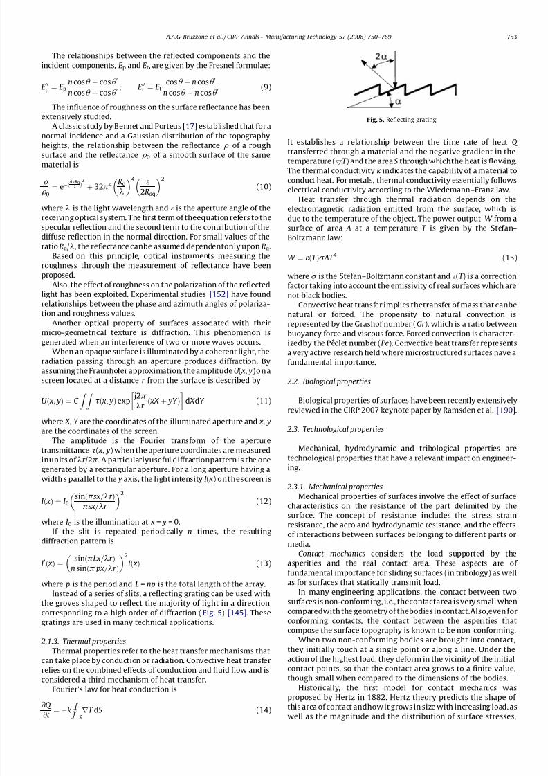
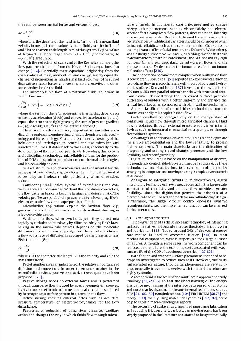
Instead of a series of slits, a reflecting grating can be used with
the groves shaped to reflect the majority of light in a direction
corresponding to a high order of diffraction (Fig. 5) [145]. These
gratings are used in many technical applications.
2.1.3. Thermal properties
Thermal properties refer to the heat transfer mechanisms that
can take place by conduction or radiation. Convective heat transfer
relies on the combined effects of conduction and fluid flow and is
considered a third mechanism of heat transfer.Fourier’s law for heat conduction is
@Q
@t ¼ Àk
I S rT dS (14)
It establishes a relationship between the time rate of heat Q
transferred through a material and the negative gradient in the
temperature (5T ) and the area S through whichthe heat is flowing.
The thermal conductivity k indicates the capability of a material to
conduct heat. For metals, thermal conductivity essentially follows
electrical conductivity according to the Wiedemann–Franz law.
Heat transfer through thermal radiation depends on the
electromagnetic radiation emitted from the surface, which is
due to the temperature of the object. The power output W from a
surface of area A at a temperature T is given by the Stefan–
Boltzmann law:
W ¼ eðT Þs AT 4 (15)
where s is the Stefan–Boltzmann constant and e(T ) is a correction
factor taking into account the emissivity of real surfaces which are
not black bodies.
Convective heat transfer implies thetransfer of mass that canbe
natural or forced. The propensity to natural convection is
represented by the Grashof number (Gr ), which is a ratio between
buoyancy force and viscous force. Forced convection is character-
izedby the Peclet number (Pe). Convective heat transfer represents
a very active research field where microstructured surfaces have a
fundamental importance.
2.2. Biological properties
Biological properties of surfaces have been recently extensively
reviewed in the CIRP 2007 keynote paper by Ramsden et al. [190].
2.3. Technological properties
Mechanical, hydrodynamic and tribological properties are
technological properties that have a relevant impact on engineer-
ing.
2.3.1. Mechanical properties
Mechanical properties of surfaces involve the effect of surface
characteristics on the resistance of the part delimited by the
surface. The concept of resistance includes the stress–strain
resistance, the aero and hydrodynamic resistance, and the effects
of interactions between surfaces belonging to different parts or
media.Contact mechanics considers the load supported by the
asperities and the real contact area. These aspects are of
fundamental importance for sliding surfaces (in tribology) as well
as for surfaces that statically transmit load.
In many engineering applications, the contact between two
surfaces is non-conforming, i.e., thecontactarea is very small when
comparedwith the geometry of thebodies in contact.Also,even for
conforming contacts, the contact between the asperities that
compose the surface topography is known to be non-conforming.
When two non-conforming bodies are brought into contact,
they initially touch at a single point or along a line. Under the
action of the highest load, they deform in the vicinity of the initial
contact points, so that the contact area grows to a finite value,
though small when compared to the dimensions of the bodies.Historically, the first model for contact mechanics was
proposed by Hertz in 1882. Hertz theory predicts the shape of
this area of contact andhow it grows in size with increasing load, as
well as the magnitude and the distribution of surface stresses,
Fig. 5. Reflecting grating.
A.A.G. Bruzzone et al. / CIRP Annals - Manufacturing Technology 57 (2008) 750–769 753
7/22/2019 Keynote Published
http://slidepdf.com/reader/full/keynote-published 5/20
normal and possibly tangential, transmitted across the interface.
Hertz theory was based on some key assumptions: (i) the surfaces
are continuous and non-conforming; (ii) the strains are very small,
which guarantees that the contact area (a) is much smaller than
the radii of curvature of the bodies (R) (where a ( R); (iii) the
contact is fully elastic; (iv) the surfaces are frictionless.
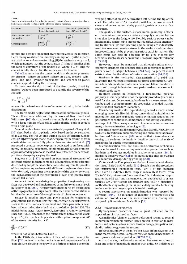
Table 2 summarises the contact widths and contact pressures
for circular (sphere-on-sphere, sphere-on-plane, crossed cylin-
ders) and line (cylinder-on-cylinder and cylinder-on-plane)
contacts as predicted by Hertz theory.
To overcome the elastic limit of the Hertz model, plasticity
indices (c) have been introduced to quantify the severity of the
contact:
c ¼ 2E Ã
H
s sR
1=2
(16)
where H is the hardness of the softer material and s s is the height
distribution.
The Hertz model neglects the effects of the surface roughness.
These effects were addressed by the work of Greenwood and
Williamson [96] that analysed a nominally flat surface covered
with a large number of asperities with spherical ends in contact
with a rigid plane.
Several models have been successively proposed. Chang et al.
[37] described an elasto-plastic model based on the conservation
of an asperity control volume during plastic deformation. Zhao
etal. [250] developeda model thatincorporates the transition fromelastic deformation to fully plastic flow and Aramaki et al. [7]
proposed a contact model expressly dedicated to surfaces with
purely longitudinal roughness. In this model, the surface profile is
approximated by parabolas located on a reference plane whose
positions change by varying the load.
Pugliese et al. [187] reported an experimental assessment of
different contact mechanics models assuming roughness profiles
described by simple parabolic functions. Starting from the profiles
of five engineering surfaces with different roughness character-
istics the study determines the amplitudes of the contact zone and
the load as a functionof theinterference of each profile with a rigid
smooth flat surface.
A contact model considering the properties of engineering sur-
faces was developed and implemented using finite element analysisby Sellgren et al. [200]. The study shows that the height distribution
of the topography has a significant influence on the contact stiffness
but that the curvature of the roughness is of minor importance.
Fatigue is another important phenomenon for engineering
applications. The mechanisms that influence fatigue crack growth,
such as the stress ratio, environment and other parameters have
been widely studied since the first article of Albert [4] in 1838. The
model for the stage II crack growth, according to Paris, widely used
since the 1960s, establishes the relationships between the crack
length ( 2a), the number of cycles N , and the cyclical componentDK
of the stress intensity factor K :
@a
@N ¼ C ðDK Þm
(17)
where m has values between 3 and 5.
In the 1970s, the introduction of the crack closure concept by
Elber [74] depicted that the mechanisms and importance of crack
‘non-closure’ slowing the growth of a fatigue crack is due to the
wedging effect of plastic deformation left behind the tip of the
crack. The reduction of DK thresholds with load determines crack
closure influenced essentially by plasticity, oxide or crack surface
roughness.
The quality of the surface, surface micro-geometry, defects,
etc., determine stress concentrations or supply crack nucleation
sites that lower the fatigue life. Notably surface stress can be
intentionally controlled to increase fatigue life. Surface engineer-
ing treatments like shot peening and ballizing are industriallyused to cause compressive stress in the surface and therefore
improve fatigue life by preventing surface crack formation. The
same effect can also be obtained by utilizing modern day
techniquessuch as laser peening and ultrasonic impact treatment
[103,166].
However, it must be remarked that although surface micro-
geometry, hardness and residual stress are recognized to have a
primary role in fatigue behaviour [244,245], no general model
exists to describe the effects of surface preparation [84,139].
Hardness is the mechanical characteristic of a solid that
quantifies the material’s resistance to plastic deformation. Hard-
ness depends on atomic, intermolecular and lattice bonds: it is
measured through indentation tests performed on a macroscopic
or microscopic scale.
Hardness cannot be considered a fundamental material
property, as it is dependent upon the specific procedure (standard)
used for the test. Consequently, hardness is a measurement that
can be used to compare materials properties, provided that the
same standard procedure is adopted.
Considering small scales, typical of engineered surfaces and of
emerging materials, like thin films, conventional uniaxial tensile
indentation tests give no reliable results. With scale reduction, the
postulations of continuous, homogeneous and isotropic materials
no longer hold. The consequences are of paramount importance on
many micro-engineering technologies [5].
For brittle materials like monocrystalline Si and LiNbO3, brittle
to ductile transition in micromachining and microindentation can
be observed. Shimada et al. [202] reported that microindentation
testing can evaluate the intrinsic ductility and critical scale of machining for ductile mode machining.
Microindentation tests are quasi-non-destructive techniques
that can be used for evaluating mechanical properties such as
hardness and Young’s modulus in a nanometer range [26], for
modelling abrasive wear [53] or for investigating phenomena such
as sub-surface damage during grinding [220].
Vickers and the Knoop tests are the best known microindenta-
tion tests. The ISO14577 standard [121] establishes the procedures
for instrumented indentation tests. Part 1 of the standard
(ISO14577-1) indicates three ranges: macro (test forces from
2 N to 30 kN), micro (test force less than 2 N; indentation depth
greater than 0.2mm) and nano (indentation depth equal to or less
than 0.2mm). Part 4 of the ISO standard (ISO14577-4) specifies a
method for testing coatings that is particularly suitable for testingin the nano/micro range applicable to thin coatings.
A recent assessment on nanoindentation was reported by
Hermann [104]. The influence of indenter tip geometries and
calibration procedures on the measurement of a coating was
analysed by Bouzakis and Michailidis [24].
2.3.2. Hydrodynamic properties
Hydrodynamic properties have a great influence on the
applications of structured surfaces.
At small scales (channel diameters of around 100 nm to several
hundred micrometers), surface forces prevail in relation to mass
forces, and factors such as surface tension, energy dissipation, and
fluidic resistance govern the system.
Hence thefluidflow at the micro-scale acts differentlyfrom thatin the macroscopic scale. Complete reviews on fluid mechanics in
micro/nano-scale are reported in [88,210,217].
At small scales, the Reynolds number (Re) assumes values at
least one order of magnitude smaller than unity. Re is defined as
Table 2
Stress and deformation formulae for normal contact of non-conforming elastic
bodies according to Hertz; E* is the effective elastic modulus.
Parameter Circular contact
(diam. = 2a, load = W )
Line contact (width = 2a,
load = W 0/unit length)
Semi-contact radius
or width
3WR
4E Ã
1=3 W 0R4E Ã
1=2
Contact pressure6WE Ã2
p3
R
2 !1=2
W 0E Ã
pR
1=2
A.A.G. Bruzzone et al. / CIRP Annals - Manufacturing Technology 57 (2008) 750–769754
7/22/2019 Keynote Published
http://slidepdf.com/reader/full/keynote-published 6/20
the ratio between inertial forces and viscous forces:
Re ¼ rvsL
m(18)
where r is the density of the fluid in kg/m3, vs is the mean fluid
velocity in m/s, m is the absolute dynamic fluid viscosity in N s/m2
and L is the characteristic length in m, of the system. Typical values
of Reynolds number range from $1 Â 10À2 (spermatozoa) to
$5 Â 10
9
(large ship).With the reduction of scale and of the Reynolds number, the
flow patterns that come from the Navier–Stokes equations also
change [112]. Essentially these equations, originating from the
conservation of mass, momentum, and energy, simply equal the
changes of momentum in infinitesimal fluid volumes to the sum of
dissipative viscous forces, changes in pressure, gravity, and other
forces acting inside the fluid.
For incompressible flow of Newtonian fluids, equations in
vector form are
r@n
@t þ nrn
¼ Àr pþmr2nþ f (19)
where the term on the left, representing inertia that depends on
unsteady acceleration (@n
/@
t ) and convective acceleration (nÁ5n
),
equals the term on the right given by the sum of pressure gradient
(À5 p), viscosity (m52n) and the external forces f .
These scaling effects are very important in microfluidics, a
discipline embracing engineering, physics, chemistry, microtech-
nology and biotechnology. Microfluidics concerns the study of the
behaviour and techniques to control and use microliter and
nanoliter volumes. It dates back to the 1980s, specifically to the
development of the first inkjet printheads. Nowadays, thanks to its
multidisciplinary technology, microfluidics allows for the produc-
tion of DNA chips, micro-propulsion, micro-thermal technologies,
and lab-on-a-chip devices.
Surface structure and characteristics are fundamental for the
progress of microfluidics applications. In microfluidics, inertial
forces play an irrelevant role, particularly when dimensions
reduce.
Considering small scales, typical of microfluidics, the con-
vective acceleration vanishes. Without this non-linear convection,
the flow patterns basically become laminar and deterministic. The
velocity profiles are parabolicin pressure-driven flows,plug-like in
electro-osmotic flows, or a superposition of both.
Microfluidics applications exploit the laminar flow, e.g.,
genomic material can be transported easily without shearing in
a lab-on-a-chip device.
With laminar flow, when two fluids join, they do not mix
rapidly by turbulence, but slowly by diffusion, obeying Fick’s laws.
Mixing in the micro-scale devices depends on the molecular
diffusion and could be unacceptably slow. The rate of advection of
a flow to its rate of diffusion is captured by the dimensionless
Peclet number (Pe):
Pe ¼ Lv
D(20)
where L is the characteristic length, v is the velocity and D is the
mass diffusivity.
Peclet number gives an indication of the relative importance of
diffusion and convection. In order to enhance mixing in the
microfluidic devices, passive and active techniques have been
proposed [173].
Passive mixing needs no external forces and is performed
through transverse flow induced by special geometries (grooves,
rivets, or posts) set in microchannels, or local circulations induced
by heterogeneous surface pattern in electrokinetic flows.
Active mixing requires external fields such as acoustics,pressure, temperature, or electrohydrodynamics for the flow
disturbance.
Furthermore, reduction of dimensions enhances capillary
action and changes the way in which fluids flow through micro-
scale channels. In addition to capillarity, governed by surface
energy, other phenomena, such as viscoelasticity and electro-
kinetic effects, complicate flow patterns, since their non-linearity
increases at small scales. Besides the Reynolds number Re and the
Peclet number Pe, additional variables should be considered when
facing microfluidics, such as the capillary number Ca, expressing
the importance of interfacial tension, the Deborah, Weissenberg,
and elasticity numbers De, Wi, and El, describing elastic effects due
to deformable microstructural elements, the Grashof and Rayleighnumbers Gr and Ra, describing density-driven flows and the
Knudsen number Kn, describing the importance of noncontinuum
molecular effects [210].
The phenomena become more complex when multiphase flow
is considered.Cubaud et al. [51] reported an experimental study on
two-phase flow in microchannels with hydrophobic and hydro-
philic surfaces. Kuo and Peles [137] investigated flow boiling in
200 mm  253 mm parallel microchannels with structured reen-
trant cavities, demonstrating that structured surfaces promote
nucleation of bubbles with a better uniformity and enhance the
critical heat flux when compared with plain wall microchannels.
A first classification of microfluidics technologies concerns
continuous or digital (droplet-based) flow.
Continuous-flow technologies rely on the manipulation of
continuous liquid flow through microfabricated channels. Fluid
flow is obtained through external pressure sources or internal
devices such as integrated mechanical micropumps, or through
electrokinetic systems.
Advantages of continuous-flow microfluidics technologies are
the simple implementation and the low sensitivity to protein
fouling problems. The main drawbacks are the difficulties of
integrating and scaling closed channel processes and the low
flexibility and reconfigurability.
Digital microfluidics is based on the manipulation of discrete,
independently controllable droplets on an open substrate. By these
technologies, microfluidics functions can be implemented by
arranging basicoperations, moving the single droplet over one unit
of distance.
Analogous to integrated circuits in microelectronics, digitalmicrofluidic technologies have a great potential in the large-scale
automation of chemistry and biology; they provide a greater
flexibility, since the digitization permits the adoption of a
hierarchical and cell-based approach for microfluidic chip design.
Furthermore, the single droplet control endorses dynamic
reconfigurability, i.e., the implemented function can be changed
during operations.
2.3.3. Tribological properties
Tribologyis defined as the science and technology of interacting
surfaces in relative motionand embraces the study of friction, wear
and lubrication [115]. Today, around 30% of the world energy
consumption is used to overcome friction [238]. In most
mechanical components, wear is responsible for a large numberof failures. Although in some cases the worn component can be
replaced before failure, the economic costs associated with wear
surpass 5% of the GDP of developed countries [127,128].
Both friction and wear are surface phenomena that need to be
properly investigated to reduce such costs. However, due to its
surface/interface nature, tribological phenomena are very com-
plex, generally irreversible, evolve with time and therefore are
highly systemic.
A recent trend is the search for a multi-scale approach to study
tribology [31,52,156], so that the understanding of the energy
dissipative mechanisms at the interface between solids at atomic
and molecular levels, using both experimental techniques, such as
AFM [21,105,159], nanoindentation [104], FIB-HRTEM [68,76] and
theory [109], mainly using molecular dynamics [157,182], couldhelp to explain macro-tribological aspects.
The texturing of surfaces as a means of improving lubrication
and reducing friction and wear between moving parts has been
largely proposed in the literature and started to be systematically
A.A.G. Bruzzone et al. / CIRP Annals - Manufacturing Technology 57 (2008) 750–769 755
7/22/2019 Keynote Published
http://slidepdf.com/reader/full/keynote-published 7/20
investigated in the last two decades. For example, the potential of
the texturing of surfaces with patterns containing plateaux and
valleys to improve the tribological performance and shorten the
running-in period of components has been the focus in the
production of engine components. This section will discuss the
main theoretical aspects related to tribology and the latest
achievements in this area towards a more fundamental under-
standing of friction and wear. It will include surface characteriza-
tion, friction, wear and lubrication. Eachsub-section reports brieflythe main models.
2.3.4. Surface characterization
All solid surfaces present some surface topography when
regarded at a sufficiently small scale. The real contact between
sliding surfaces occurs at the summits of the higher asperities,
where friction and wear occur. Techniques to analyse this surface
topography include light or electron microscopy [186], stylus
profilometry [133,135], optical interferometry [40], tunnelling
microscopy [93], AFM [135,147] or indirect measurements such as
electrical [60] or thermal [65] measurements. The quantificationof
surface topography makes use of roughness, waviness and form
error parameters, which have been intensively discussed and used
in engineering [14,89,99].
2.3.5. Contact mechanics for sliding surfaces
In order to understand the tribology of textured surfaces, it is
important to first define some concepts related to the contact
mechanics of two sliding surfaces. In this section, the basic
theoretical concepts related to contact mechanics in non-
conforming contacts for tribology are summarised.
In tribology, the contact pressure between the asperities is
generally very high and therefore plastic in many cases. For
example, if the indenter (or asperity) is spherical, indentation
hardness testing theory predicts that plastic flow first occurs at a
depth of about 0.47a at a mean contact pressure of 1.1Y (uniaxial
yield stress). With the increase of the normal load, plastic
deformation extends from beneath the contact until it eventually
reaches the surface. At this point the mean contact pressureachieves approximately 3Y and does not increase further. Such
findings lead to the assumption that for any shape of asperity
pressed against an opposing surface, the mean contact pressure
will always be around three times the unixial yield stress (Y ) of the
softer materials and the area of contact will be directly
proportional to the load [115].
In real surfaces, statistical theories of multiple asperity contact
take into consideration the fact that surface irregularities are
statistically distributed and analyse the probability that one
asperity will touch an opposing surface [96].
2.3.6. Lubrication of sliding surfaces
The presence of a lubricant film between two sliding surfaces
reduces friction and wear. If the surfaces are sliding against eachother with a certain velocity and a lubricant fluid is present in
the contact, a hydrodynamic film may form spontaneously
between them. This condition is known as hydrodynamic or full-
film lubrication. However, depending on the operating conditions,
the formation of a thick fluid film between the surfaces may not
occur and the lubrication will need to rely on other mechanisms.
When the surfaces possess a micro-topography, it can
considerably change the pressure distribution, the hydrodynamic
action of the fluid and the deformation of the surfaces, leading to
differences in the lubrication conditions of the surfaces. These
differences can be positive or negative in terms of the tribological
performance, depending on the characteristics of the topography
[197].
For situations involving full-film lubrication, the effect textur-ing has on increasing the hydrodynamic pressure between the two
sliding surfaces has been analysed both via numerical simulation
and experimental investigation. The first evidences of the effect of
irregularities on the hydrodynamic lubrication was found by
Hamilton et al. [102]. This was based on visual observation of non-
continuous lubrication films in optically flat, transparent seals. The
film was interrupted by numerous long, narrow cavitation
streamers, which appeared to originate and terminate on locations
corresponding to irregularities on the stator surface. Based on
these observations, the authors produced a simple analytical
model to predict the effect of the geometry of micro-irregularities
on the load support of face seals by hydrodynamic lubrication.
They used the Reynolds equation reduced to the two-dimensionalform of the Laplace equation to describe the flow.
In order to understand the possible effect of a micro-texture in
increasing the hydrodynamic pressure between two sliding
surfaces, it is necessary to examine the hydrodynamic effect that
occurs dueto thepresence of a geometrical wedge. The variationof
lubricant pressure in a bearing is described by the Reynolds
equation, which can be applied to model the hydrodynamic action
on the basis of a convergent clearance space through the length of
the bearing. It allows the pressuredistribution andload capacity to
be determined [212,238].
For textured surfaces, the micro-topographies that have offered
the best tribological results consist of small cavities uniformly
distributed over the sliding surface. Considering the micro-
converging wedges generated by each one of these pockets,
textured surfaces composed of a plurality of pockets could be
regarded as a set of micro-bearings [47].
In non-conforming contacts, such as gear teeth,piston rings and
cam followers, the pressure is very high. If hydrodynamic
equations are applied to suchcontacts, the predictedfilm thickness
is very small and would not prevent metallic contact of the surface
asperities. However, in practice these systems operate quite
satisfactorily. This indicates that thicker films must be present. The
mechanisms responsible for this are the variation of the viscosity
with high pressures and, to a large extent, the elastic deformation
of the bearing surfaces [101]. This condition is called elastohy-
drodynamic lubrication (EHL).
It has been established recently that some engineering
components can have roughness features that are of the same
order as or even significantly larger than the predicted thickness of the EHL film. Consequently, they operate under conditions
described as partial, mixed or micro-EHL [75].
Studies of EHL and micro-EHL of surfaces containing dents and
grooves have also been intensively conducted [130,178,209].
Although the main objective of these studies is to determine
stresses around surface defects that compose the surface
topography of engineering components, in order to understand
surface-originated fatigue failures, they show that the surface
topography itself is intimately involved in the lubrication process.
These studies have been mostly carried out by optical inter-
ferometry of artificially produced surface features. Obviously, they
can also help to understand the effect of a well-defined surface
texture on EHL and micro-EHL.
Undervery high contact pressures, or at very lowsliding speeds,hydrodynamic forces are insufficient to maintain even a thin EHL
film and direct contact will occur between the asperities. In these
cases, the surface must be protected by a suitable boundary
lubricant and this regime is known as boundary lubrication [115].
2.3.7. Friction of textured surfaces
Frictionis definedas theresistanceencounteredby onebody in
moving over another. It occurs as a result of the interactionsin the
real contact area of solids, i.e., around the contacting asperities.
Friction depends on both the materials in contact and the
tribological system; therefore it is not an intrinsic property of
the contacting pair.
The texturing of surfaces, especially in meso-scale or macro-
scale, is traditionally used to increase the friction of parts[120,183]. Coefficients of friction as high as 1.6 were measured
for the sliding of specially designed textures [183].
Friction between sliding surfaces can also be reduced by
texturing in a micrometric scale. The two main reasons ascribed to
A.A.G. Bruzzone et al. / CIRP Annals - Manufacturing Technology 57 (2008) 750–769756
7/22/2019 Keynote Published
http://slidepdf.com/reader/full/keynote-published 8/20
this reduction of friction are entrapping of wear debris inside the
pattern features [16,72,131,184,197,225,230], and improvement
of lubrication [22,48,77,92,110,194,196,231–233].
2.3.8. Wear of textured surfaces
Wear is themaincausefor materialswasteand efficiency loss in
mechanical components.
In many situations, the wear between two sliding surfaces can
be reduced by surface texturing. Various authors have studied thewear of textured surfaces [86,123,184,213]. These studies include
mainly experimental evaluation of textured surfaces.
Three main effects seem to contribute to reduce the wear of
textured surfaces. The first is the entrapment of wear debris inside
the pockets that compose the texture, avoiding their presence
between the two surfaces, which could cause abrasive wear. The
second is the fact that very smooth lubricated surfaces for both
moving and stationary contacting parts usually show poor
behaviour because they may not have sufficient oil-holding
capacity to ensure lubrication at the contact. The existence of
pockets of lubricant could be particularly useful as a secondary
source of lubricant, especially in conditions involving high plastic
deformation. The third is the enhancement of a hydrodynamic
pressure between the surfaces due to the converging wedges
constituted by the pockets.
3. Applications
A great number of applications are based on engineered
surfaces. Many industrial applications for engineered surfaces are
described or suggested in literature and patent databases. The
most interesting emerging applications for industry and for the
research community are reported. The list, which is not exhaustive,
includes applications and advances in the fields of energy,
microfluidics, optics, bioengineering, cleaning, and manufacturing.
3.1. Energy
Interesting applications related to energy transfer have beendeveloped in different industrial sectors, such as aerospace, power
plants and electronics.
The role played by structured surfaces in heat transfer
phenomena, based particularly on spray and boiling mechanisms,
has been investigated by many authors. Microstructured surfaces
increase the coolant-solid contact area. However, this aspect alone
does not explain the observed enhancement in heat transfer rate.
A fundamental design parameter in advanced applications of
heat transfer is thecritical heat flux (CHF) that canbe attained;it is
defined as the heat supplied to the heater that just balances the
liquid heat removal capability. For spray cooling, CHF is usually
higher than for boiling, since the vapor produced at the surface by
phase change can be much more easily removed from the surface.
3.1.1. Spray cooling
Spray cooling is very efficient for dissipating high heat fluxes
with low coolant mass fluxes at low and high wall superheats
[132]. Applications of this technology include the Cray X-1
computer cooling system and the Space Shuttle’s open loop flash
evaporator system (FES), where the cyclic water spray of surfaces
enhanced with triangular grooves cools Freon-based heat exchan-
gers [171]. Besides cooling applications used in supercomputing
and space explorations for on-board flight system components,
spray cooling has been used in laser-diode arrays, multi-chip
modules, metal quenching and medical treatments.
Spray cooling is a multiphase convective process that yields
high heat fluxes, greater than 100 W/cm2 using Fluorinerts, and
over 1000 W/cm2
with water. It permits precise temperaturecontrol (Æ2 8C) at low coolant fluid flow rates.
Spray cooling heat transfer can operate with three different
regimes. At low temperatures, the liquid evaporates at the free
liquid–vapor interface. At high temperatures, vapor bubbles are
produced in the liquid films at the superheated hot wall. The
transition from the low temperature to the high temperature
region characterizes the third regime.
At low wall temperatures, heat transfer is controlled by single-
phase convection. At higher wall temperatures, bubble nucleation
appears, providing considerable agitation; phase change phenom-
ena prevail andenhance heat flux. Heat transfer mechanisms in the
two-phase regime are possibly caused by: (i) thin liquid film
evaporation on the surface; (ii) secondary nucleation due to gaslayer of striking droplets; (iii) extension of the three-phase contact
line where solid, liquid and vapor phases coexist.
Several factors influence spray heat transfer. Volumetric spray
flux is preeminent on other hydrodynamicparameters of the spray.
Other factors are the ejected fluid temperature, chamber environ-
mental conditions and surface roughness.
Preliminary studies on the surface influence indicated that the
heat transfer coefficient increases with the use of smooth surfaces
(Ra < 0.1mm) for gas atomized sprays, while the opposite was
observed for liquid atomized sprays [199].
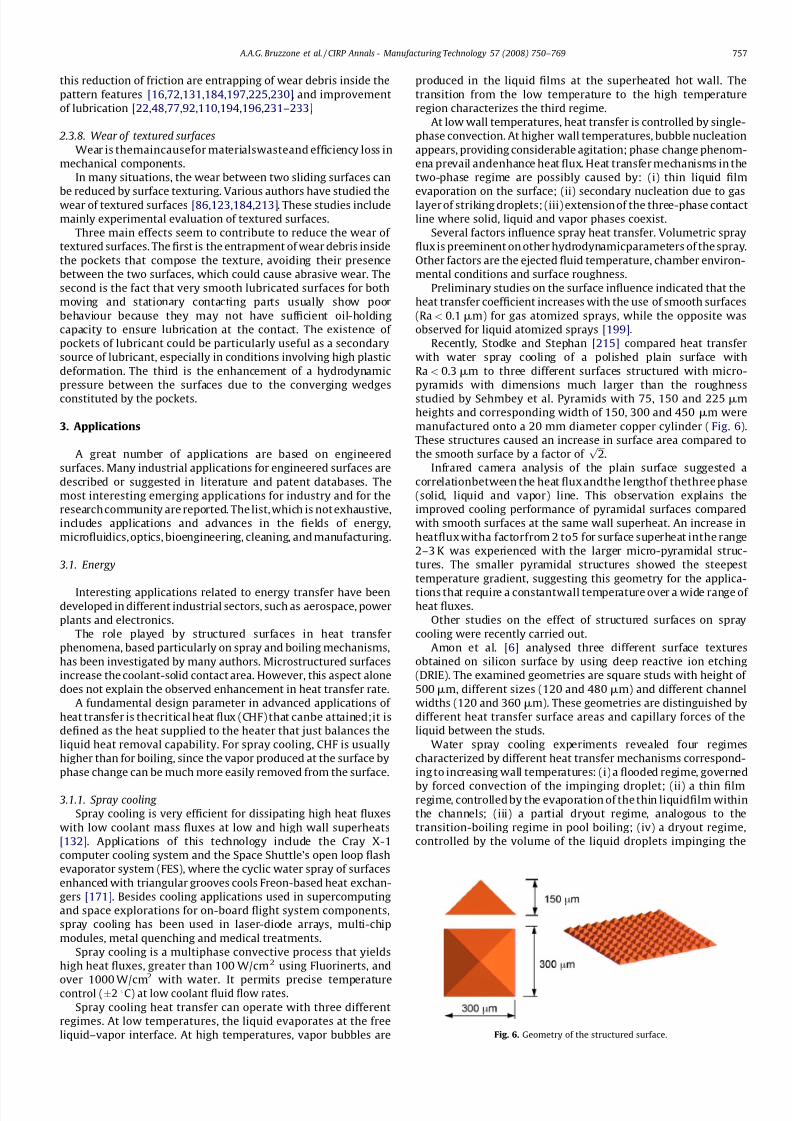
Recently, Stodke and Stephan [215] compared heat transfer
with water spray cooling of a polished plain surface with
Ra < 0.3mm to three different surfaces structured with micro-
pyramids with dimensions much larger than the roughness
studied by Sehmbey et al. Pyramids with 75, 150 and 225mm
heights and corresponding width of 150, 300 and 450 mm were
manufactured onto a 20 mm diameter copper cylinder (Fig. 6).
These structures caused an increase in surface area compared to
the smooth surface by a factor of ffiffiffi
2p
.
Infrared camera analysis of the plain surface suggested a
correlationbetween the heat flux andthe lengthof thethree phase
(solid, liquid and vapor) line. This observation explains the
improved cooling performance of pyramidal surfaces compared
with smooth surfaces at the same wall superheat. An increase in
heatflux witha factorfrom 2 to5 for surface superheat inthe range
2–3 K was experienced with the larger micro-pyramidal struc-
tures. The smaller pyramidal structures showed the steepest
temperature gradient, suggesting this geometry for the applica-
tions that require a constantwall temperature over a wide range of heat fluxes.
Other studies on the effect of structured surfaces on spray
cooling were recently carried out.
Amon et al. [6] analysed three different surface textures
obtained on silicon surface by using deep reactive ion etching
(DRIE). The examined geometries are square studs with height of
500mm, different sizes (120 and 480mm) and different channel
widths (120 and 360 mm). These geometries are distinguished by
different heat transfer surface areas and capillary forces of the
liquid between the studs.
Water spray cooling experiments revealed four regimes
characterized by different heat transfer mechanisms correspond-
ing to increasing wall temperatures: (i) a flooded regime, governed
by forced convection of the impinging droplet; (ii) a thin filmregime, controlled by the evaporation of the thin liquidfilm within
the channels; (iii) a partial dryout regime, analogous to the
transition-boiling regime in pool boiling; (iv) a dryout regime,
controlled by the volume of the liquid droplets impinging the
Fig. 6. Geometry of the structured surface.
A.A.G. Bruzzone et al. / CIRP Annals - Manufacturing Technology 57 (2008) 750–769 757
7/22/2019 Keynote Published
http://slidepdf.com/reader/full/keynote-published 9/20
surface. The structured surface with finerstuds provides the higher
heat flux and the most uniform surface temperature.
Analogous results were found by Hsieh and Yao [111] for silicon
and aluminum surfaces with the same square stud geometries.
They report that the Bond number (Bo) can characterize the
capillary forces between the micro-studs and, therefore, wett-
ability. Microstructured surfaces improve the spreading of the
impinging droplets, the formation of a thinner liquid film and
permit the full liquid film wetting in order to achieve higher heatfluxes. Bond number compares the gravitational force and the
surface tension force:
Bo ¼ G ffiffiffiffiffiffiffiffiffiffiffiffiffiffiffiffiffiffiffiffiffiffiffiffiffiffiffiffig =ðrl À rvÞ g
p (21)
where G is the groove width (m), g is the surface tension (N/m), rland rv are the liquid and vapor densities (kg/m3) and g is the
gravitational constant (N/s2).
Smaller Bo values characterize microstructures with narrower
grooves and higher thermal flux. The effect of capillary forces
disappears when grooves are too small for allowing good liquid
penetration and flow. Structured surfaces give important improve-
ments in the thin film and in the partial dryout regime. In the
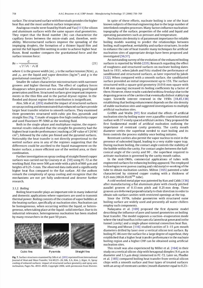
flooded and dryout regime their contribution is insignificant.Also, Silk et al. [203] studied the impact of structured surfaces
on spraycooling and demonstrated that enhanced surfaces provide
larger heat transfer relative to smooth surfaces. They examined
three geometries structured with cubic pin fins, pyramids and
straight fins (Fig. 7) made of oxygen-free high conductivity copper
and used Fluorinert PF-5060 as the working fluid.
Both in the single-phase and multiphase regime, the experi-
mental results indicated that the straight fin geometry had the
highest heat transfer performance (reaching a CHF value of 126 W/
cm2), followed by the cubic pin finned and the pyramid surfaces.
Noticeably the heat transfer is not directly proportional to the
wetted surface area in any of the regimes suggesting that the
differences could be ascribed to the liquid management on the
heater surface, a more efficient use of the wetted area, or their
combination.
Further investigation on spray cooling of straight finned copper
surfaces was carried out by Coursey et al. [50] using FC-72 as the
working fluid. Fins were 500mm wide with a pitch of 860 mm and
heights of 0.25–5 mm. The observed data indicated a significantly
higher heat flux compared to the flat surface. All the authors
remark the complexity of spray cooling and recognize that the
mechanisms are not yet fully understood and deserve further
research.
3.1.2. Boiling
Boiling heat transfer plays an important role in many industrial
and domestic applications where vaporizers are used to transmit
thermal power. Boiling consists of the creation of vapor bubbles at
the heating surface, specifically at nucleation sites. Nucleation canbe homogeneous, when occurring within the liquid, or hetero-
geneous, when taking place at the liquid–solid interface. Due to its
industrial relevance, heterogeneous nucleation has been studied
by many researchers in the past 50 years.
In spite of these efforts, nucleate boiling is one of the least
known subjects of thermal engineering due to the large number of
interlinked complex processes. Many factors influence nucleation:
topography of the surface, properties of the solid and liquid and
operating parameters such as pressure and temperature.
Nucleation site density is of paramount importance for reliable
boiling models wanting to predict the relationships between
boiling, wall superheat, wettability and surface structures. In order
to enhance the rate of heat transfer many techniques for artificialnucleation sites of appropriate design have been proposed and
investigated [56,57].
An outstanding survey of the evolution of the enhanced boiling
surfaces is reported by Webb [235]. Research regarding the effect
of roughness and structured surfaces on nucleate boiling dates
back to 1931, when Jakob and Fritz studied the performance of
sandblasted and structured surfaces, as later reported by Jakob
[122]. When compared with a smooth surface, the sandblasted
surface provided an initial improvement up to 15%. The surface
structured with a square grid geometry (0.016 mm square with
0.48 mm spacing) increased its boiling coefficients by a factor of
three. However, these results vanished withina fewdays due to the
degassing process of the cavities that eventually didnot stably trap
vapor. Scientific interest renewed in the 1950s [18,45,138]
establishing that boiling enhancement depends on the site density
of stable nucleation sites and suggested investigations to multiply
artificial nucleation sites.
Griffith and Wallis [97] first studied the effects of artificial
nucleation sites by boiling water over a paraffin-coated horizontal
surface with 37 evenly spaced artificial cavities. They proposed the
first fundamental model of artificial nucleation outlining the
importance of reentrant cavity geometry. The cavity mouth
diameter settles the superheat needed to start boiling and its
form controls the process stability once boiling initiates.
Reentrant cavities also permit the vapor nucleus to exist in the
presence of subcooled liquid, leading to a very stable vapor trap.
During nucleate boiling, the contact angle controls the stability of
the bubble within the cavity. For contact angles between the half-
conical angle of the cavity and 908, the superheat required toactivate nucleation is governed by the cavity mouth radius.
In the mid-1960s, commercial applications of tubes with
engineered surfaces for enhancing boiling appeared. The employed
technologies were porous coating and cold metal re-working of the
tube to obtain nucleation cavities. Milton [165] patented a tube
characterized by sintered copper coating with a thickness of
0.25 mm (HIGH-FLUXTM tube).
A cold worked metal pipe was patented by Kun and Czikk [136]
after manufacturing a flat aluminum plate with closely pitched
parallel grooves of 0.13 mm pitch and 0.25 mm deep. These
grooves are deformed perpendicularly to their direction in order to
obtain sub-surface cavities with restricted openings at the top.
Since the 1970s, tubular geometries with structured outer
boiling surface are widely used and presently all water chillersemploy such components.
Nakayama et al. [169] proposed the first dynamic model
describing the influence of pore and tunnel geometries on boiling
heat transfer. The model supposes a suction–evaporation mode
where the total heatflux isthe sum ofa latentheat generated inthe
tunnel (cavity) and a single-phase external convection heat flux.
Hwang and Moran [116] studied cavities of 3–15 mm mouth
diameters drilled by laser over a vertical silicon test surface. By
boiling FC-86 over the surface for a large degree of superheat, they
established that a higher heat transfer performance in the nucleate
boiling region and a higher CHF can be obtained using artificial
nucleation sites.
This result was also experienced by Miller et al. [164] in their
study on a vertical silicon chip with hexagonal dimples (9.4mm indiameter and 3.3mm deep) immersed in FC-72. Later on, Phadke
et al. [185] compared boiling heat transfer from vertical silicon
chips with a smooth surface and four types of treated surfaces
with an array of reentrant cavities (mouth diameter equal to 0.23–
Fig. 7. Surface structures examined by Silk et al. [203] reprinted from International
Journal of Heat and Mass Transfer, Vol 49/25 –26, Silk, E.A., Kim, J., Kiger, K., Spray
cooling of enhaced surfaces: impact of structured surface geometry and spray axis
inclination, Pages No. 4910–4920, Copyright 2006, with permission from Elsevier.
A.A.G. Bruzzone et al. / CIRP Annals - Manufacturing Technology 57 (2008) 750–769758
7/22/2019 Keynote Published
http://slidepdf.com/reader/full/keynote-published 10/20
0.49 mm) immersed in R-113. Data concerning saturated boiling
indicated that all the treated surfaces decrease the required
superheat considerably when compared with a smooth surface.
In 1998, Chien and Webb [39] demonstrated, using flow
visualization, the correctness of the Nakayama et al. suction and
evaporation model for saturated boiling at typical operational heat
fluxes.
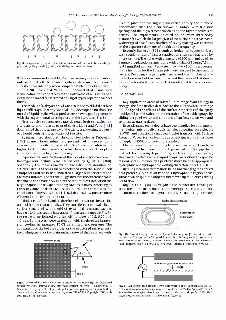
The models of Nakayamaet al. and Chein and Webb did not face
liquid refill stage. Recently Das et al. [56] developed a mechanistic
model of liquid intake whose predictions shows a good agreement
with the experimental data reported in the literature (Fig. 8).
Heat transfer enhancement rate depends both on nucleation
site density and the activation of cavity. Liang and Yang [148]
determined that the geometry of the cavity and wetting property
of a liquid controls the activation of the site.
By using micro-electronic fabrication technologies, Kubo et al.
[134] manufactured inline arrangements of micro-reentrant
cavities with mouth diameter of 1.6–3.1mm and observed a
higher heat transfer performance for these surfaces than plain
surfaces also in the high heat flux region.
Experimental investigations of the role of surface structure in
heterogeneous boiling were carried out by Qi et al. [188].
Specifically the measurements of nucleation site densities on
stainless steel and brass surfaces polished with the same siliconsandpaper (400 mesh size) indicated a larger number of sites on
the brass surfaces. The authors suggested that the difference could
depend on the smaller cavity sizes of the stainless steel or on the
larger population of vapor trapping cavities of brass. According to
this study only the deep cavities can trap vapor in contrast to the
conclusion of Messina and Park [162] that shallow pits are more
efficient for nucleation site formation.
Nimkar et al. [175] studied the effect of nucleation site spacing
on pool boiling characteristics. They considered a vertical silicon
surface structured with a grid of pyramidal reentrant cavities
having a 240 mm square base and a 40 mm square mouth (Fig. 9);
the test was performed on grids with pitches of 0.5, 0.75 and
1.0 mm. Boiling tests were carried out with single-phase immer-
sion cooling in saturated FC-72 at atmospheric pressure. Thecomparison of the boiling curves for the structured surfaces with
the boiling curve for the plain surface showed that a surface with
0.5 mm pitch and the highest nucleation density had a worse
performance than the plain surface. A surface with 0.75 mm
spacing had the highest heat transfer and the highest active site
density. The experiments indicated an optimum inter-cavity
distance for which the largest part of the surface is active over a
wide range of heat fluxes. No effect of cavity spacing was observed
on the departure diameter of bubbles and frequency.
Recently Das et al. [57] examined horizontal copper surfaces
with regular arrays of discrete nucleation sites manufactured bymicro-drilling. The holes with diameters of 600 mm and depth to
2 mm,were placedon a squaregrid with pitches of 10 mm,7.5 mm
and 5 mm.Boilingin distilledwater indicateda 100% improvement
in the heat flux for the 10 mm pitch with respect to the smooth
surface. Reducing the grid pitch increased the number of the
nucleation sites but the gain on the heat flux reduced fast due to
the interactionsbetween the nucleation sitesthat behaved as small
pumps.
3.2. Microfluidics
Key application areas of microfluidics range from biology to
energy. The first studies date back to the 1960s when Furmidge
[87] analysed the effects of the surface properties of the spray
liquid/solid combination on the retention of pesticide sprays by
sliding drops of water and solutions of surfactants on wax and
cellulose acetate surfaces.
Recently many technologies have been studied for implement-
ing digital microfluidics such as electrowetting-on-dielectric
(EWOD) and acoustically induced droplet transport with Surface
Acoustic Waves. Surface fouling due to proteins is a limiting factor
for applying EWOD to biological samples.
Microfluidics applications involving engineered surfaces have
been proposed by many authors. Aggarwal et al. [3] suggested a
method for moving liquid along surfaces by using purely
electrostatic effects where liquid drops are confined to specific
regions of the substrate by a printed pattern that has appropriate
hydrophilic and hydrophobic wetting characteristics (Fig. 10).
By using localized electrostatic fields and changing the appliedfield pattern, a blob of oil kept on a hydrophobic region of the
surface can be split into droplets and moved up to 15 cm/s causing
liquid flow.
Buguin et al. [34] investigated the ratchet-like topological
structures for the control of microdrops. Specifically liquid
microdrops confined in asymmetrically structured geometries
Fig. 8. Evaporation process in the sub-surface tunnel for one bubble cycle: (a)
preparatory, (b) growth, (c) refill, and (d) depressurization phases.
Fig. 11. Scheme of drop actuated by electrowetting on structured surfaces [34]
(with kind permission from Springer Science+Business Media: Applied Physics A,
Ratchet-like topological structures for the control of microdrops, Vol 75/2, 2002,
pages 209, Buguin, A., Talini, L., Silberzan, P, figure 4).
Fig.9. Structuredsiliconsurface with0.75 mm inter-cavity spacing [175] (reprinted
from International Journal of Heat and Mass Transfer, Vol 49/17–18, Nimkar, N.D.,
Bhavnani, S.H., Jaeger, R.C., Effect of nucleation site spacing on the pool boiling
characteristics of a structured surface, Pages No. 2829–2839, Copyright 2006, with
permission from Elsevier).
Fig. 10. Closed loop geometry of hydrophobic regions [3] (reprinted with
permission from Journal of Applied Physics, Vol 99, Aggarwal, J., Kotlicki, A.,
Mossman, M., Whitehead,L., Liquidtransport based on electrostatic deformation of
fluid interfaces, page 104904, Copyright 2006, American Institute of Physics).
A.A.G. Bruzzone et al. / CIRP Annals - Manufacturing Technology 57 (2008) 750–769 759
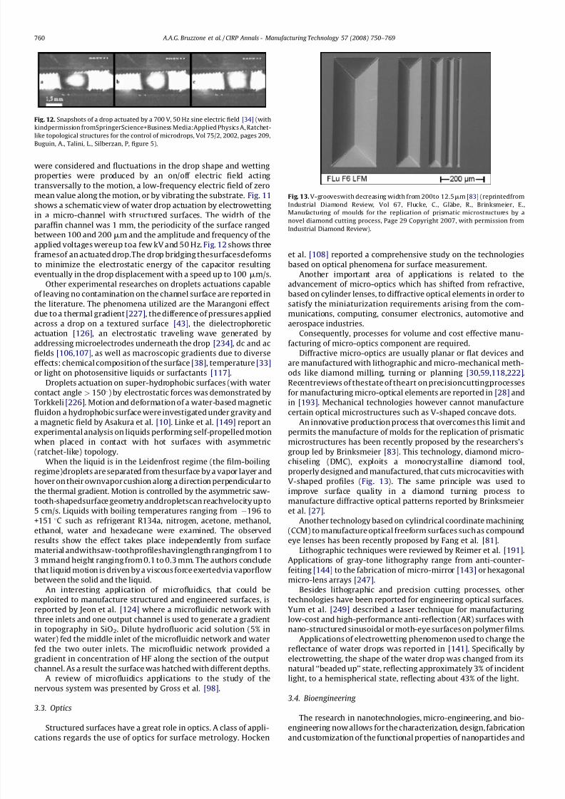
7/22/2019 Keynote Published
http://slidepdf.com/reader/full/keynote-published 11/20
were considered and fluctuations in the drop shape and wetting
properties were produced by an on/off electric field acting
transversally to the motion, a low-frequency electric field of zero
mean value along the motion, or by vibrating the substrate. Fig. 11
shows a schematic view of water drop actuation by electrowetting
in a micro-channel with structured surfaces. The width of the
paraffin channel was 1 mm, the periodicity of the surface ranged
between 100 and 200 mm and the amplitude and frequency of the
applied voltages wereup toa few kV and 50 Hz. Fig. 12 shows three
framesof an actuated drop.The drop bridging thesurfacesdeforms
to minimize the electrostatic energy of the capacitor resulting
eventually in the drop displacement with a speed up to 100 mm/s.
Other experimental researches on droplets actuations capable
of leaving no contamination on the channel surface are reported in
the literature. The phenomena utilized are the Marangoni effect
due to a thermal gradient [227], the difference of pressures applied
across a drop on a textured surface [43], the dielectrophoretic
actuation [126], an electrostatic traveling wave generated by
addressing microelectrodes underneath the drop [234], dc and ac
fields [106,107], as well as macroscopic gradients due to diverse
effects: chemical composition of the surface [38], temperature [33]
or light on photosensitive liquids or surfactants [117].
Droplets actuation on super-hydrophobic surfaces (with water
contact angle > 1508) by electrostatic forces was demonstrated by
Torkkeli [226]. Motion and deformation of a water-based magnetic
fluidon a hydrophobic surface were investigated under gravity and
a magnetic field by Asakura et al. [10]. Linke et al. [149] report anexperimental analysis on liquids performing self-propelled motion
when placed in contact with hot surfaces with asymmetric
(ratchet-like) topology.
When the liquid is in the Leidenfrost regime (the film-boiling
regime)droplets are separated from thesurface by a vapor layer and
hover on their ownvapor cushion along a direction perpendicular to
the thermal gradient. Motion is controlled by the asymmetric saw-
tooth-shapedsurface geometry anddropletscan reachvelocity up to
5 cm/s. Liquids with boiling temperatures ranging from À196 to
+151 8C such as refrigerant R134a, nitrogen, acetone, methanol,
ethanol, water and hexadecane were examined. The observed
results show the effect takes place independently from surface
material andwithsaw-toothprofileshavinglength rangingfrom 1 to
3 mmand height ranging from 0.1 to 0.3 mm. The authors concludethat liquid motion is driven by a viscous force exertedvia vaporflow
between the solid and the liquid.
An interesting application of microfluidics, that could be
exploited to manufacture structured and engineered surfaces, is
reported by Jeon et al. [124] where a microfluidic network with
three inlets and one output channel is used to generate a gradient
in topography in SiO2. Dilute hydrofluoric acid solution (5% in
water) fed the middle inlet of the microfluidic network and water
fed the two outer inlets. The microfluidic network provided a
gradient in concentration of HF along the section of the output
channel. As a result the surface was hatched with different depths.
A review of microfluidics applications to the study of the
nervous system was presented by Gross et al. [98].
3.3. Optics
Structured surfaces have a great role in optics. A class of appli-
cations regards the use of optics for surface metrology. Hocken
et al. [108] reported a comprehensive study on the technologies
based on optical phenomena for surface measurement.
Another important area of applications is related to the
advancement of micro-optics which has shifted from refractive,
based on cylinder lenses, to diffractive optical elements in order to
satisfy the miniaturization requirements arising from the com-
munications, computing, consumer electronics, automotive and
aerospace industries.
Consequently, processes for volume and cost effective manu-
facturing of micro-optics component are required.
Diffractive micro-optics are usually planar or flat devices and
are manufactured with lithographic and micro-mechanical meth-
ods like diamond milling, turning or planning [30,59,118,222].
Recentreviews of thestate of theart on precisioncuttingprocesses
for manufacturing micro-optical elements are reported in [28] and
in [193]. Mechanical technologies however cannot manufacture
certain optical microstructures such as V-shaped concave dots.
An innovative production process that overcomes this limit andpermits the manufacture of molds for the replication of prismatic
microstructures has been recently proposed by the researchers’s
group led by Brinksmeier [83]. This technology, diamond micro-
chiseling (DMC), exploits a monocrystalline diamond tool,
properly designed and manufactured, that cuts microcavities with
V-shaped profiles (Fig. 13). The same principle was used to
improve surface quality in a diamond turning process to
manufacture diffractive optical patterns reported by Brinksmeier
et al. [27].
Another technology based on cylindrical coordinate machining
(CCM) to manufacture optical freeform surfaces such as compound
eye lenses has been recently proposed by Fang et al. [81].
Lithographic techniques were reviewed by Reimer et al. [191].
Applications of gray-tone lithography range from anti-counter-feiting [144] to the fabrication of micro-mirror [143] or hexagonal
micro-lens arrays [247].
Besides lithographic and precision cutting processes, other
technologies have been reported for engineering optical surfaces.
Yum et al. [249] described a laser technique for manufacturing
low-cost and high-performance anti-reflection (AR) surfaces with
nano-structured sinusoidal or moth-eye surfaces on polymer films.
Applications of electrowetting phenomenon used to change the
reflectance of water drops was reported in [141]. Specifically by
electrowetting, the shape of the water drop was changed from its
natural ‘‘beaded up’’ state, reflecting approximately 3% of incident
light, to a hemispherical state, reflecting about 43% of the light.
3.4. Bioengineering
The research in nanotechnologies, micro-engineering, and bio-
engineering now allows for the characterization, design, fabrication
and customization of the functional properties of nanoparticles and
Fig. 12. Snapshots of a drop actuated by a 700 V, 50 Hz sine electric field [34] (with
kindpermission fromSpringerScience+Business Media:Applied Physics A, Ratchet-
like topological structures for the control of microdrops, Vol 75/2, 2002, pages 209,
Buguin, A., Talini, L., Silberzan, P, figure 5).
Fig. 13. V-grooveswith decreasing width from 200to 12.5mm [83] (reprintedfrom
Industrial Diamond Review, Vol 67, Flucke, C., Glabe, R., Brinksmeier, E.,
Manufacturing of moulds for the replication of prismatic microstructures by a
novel diamond cutting process, Page 29 Copyright 2007, with permission from
Industrial Diamond Review).
A.A.G. Bruzzone et al. / CIRP Annals - Manufacturing Technology 57 (2008) 750–769760
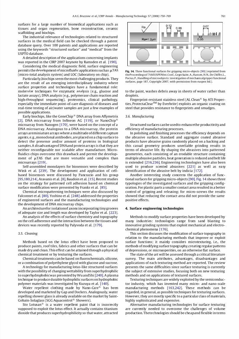
7/22/2019 Keynote Published
http://slidepdf.com/reader/full/keynote-published 12/20
surfaces for a large number of biomedical applications such as
tissues and organ regeneration, bone reconstruction, ceramic
scaffolding and biochips.
The industrial relevance of technologies related to structured
surfaces in the medical field can be checked through a patent
database query. Over 100 patents and applications are reported
using the keywords ‘‘structured surface’’ and ‘‘medical’’ from the
USPTO database.
A detailed description of the applications concerning implantswas reported in the CIRP 2007 keynote by Ramsden et al. [190].
Considering the medical diagnostic field, surface engineering
permits the development of microfluidic applications suchasmTAS
(micro-total analysis system) and LOC (laboratory on chip).
Particularly,biochips seem the most challenging products. They
are the result of an emerging interdisciplinary industry where
surface properties and technologies have a fundamental role:
molecular techniques for enzymatic analysis (e.g., glucose and
lactate assays), DNA analysis (e.g., polymerase chain reaction and
high-throughput sequencing), proteomics, clinical pathology,
especially the immediate point-of-care diagnosis of diseases and
real-time testing of air/water samples are just a few examples of
possible applications.
Early biochips, like the GeneChip1DNA array from Affymetrix
[2], DNA microarray from Infineon AG [119], or NanoChip1
microarray from Nanogen [170], were based on the concept of a
DNA microarray. Analogous to a DNA microarray, the protein
arrays areminiature arrays where a multitude of different capture
agents, e.g.,monoclonal antibodies, are placed on a chip surface to
detect the presence and/or amount of proteins in biological
samples.A disadvantageof DNAand protein arrays is that they are
neither reconfigurable nor scalable after manufacture. Micro-
fluidics chips overcome this drawback and permit the develop-
ment of mTAS that are more versatile and complex than
microarrays [219].
Self-assembled monolayers for biosensors were described by
Wink et al. [239]. The development and application of cell-
based biosensors were discussed by Pancrazio and his group
[95,180,214], Aravanis et al. [8], Baudoin et al. [15]. Recent studieson the strategy for patterned cell adhesion based on chemical
surface modification were presented by Franks et al. [85].
Chemical micropatterning techniques were also discussed by
Falconnet et al. [80]. Yoshino et al. [248] addressed the properties
of engineered surfaces and the manufacturing technologies and
the development of DNA microarray chips.
An architecturefor isolationof axons incorporating tiny grooves
of adequate size and length was developed by Taylor et al. [223].
An analysis of the effects of surface chemistry and topography
on the cell adherence and the interaction between the tissues and
devices was recently reported by Palyvoda et al. [179].
3.5. Cleaning
Methods based on the lotus effect have been proposed to
produce paints, roof tiles, fabrics and other surfaces that can be
made dry and clean. This effect can be attained through a physical/
chemical treatment or by texturing the surfaces.
Chemical treatments can be based on fluorochemicals, silicone,
or a combination of polyethylene glycol with glucose and sucrose.
A technology for manufacturing lotus-like structured surfaces
with the possibility of changing wettability from superhydrophilic
to superhydrophobicwas presented by Wu andShi [240]. A plasma
technique to produce durable hydrophilic surfaces on hydrophobic
polymer materials was investigated by Kuzuya et al. [140].
Water repellent clothing made by Nano-Care1 has been
developed and marketed by Gap and Dockers. Analogously, water
repelling shower glass is already available on the market by Saint-Gobain-Solaglass (SGG Aquacontrol1 Showers).
Sto Lotusan1 is a water repellent paint that is incorrectly
supposed to exploit the lotus effect. It actually contains titanium
dioxide that produces superhydrophilicity so that water, attracted
to the paint, washes debris away in sheets of water rather than
droplets.
Fingerprint-resistant stainless steel (AL Clean1 by ATI Proper-
ties, ProtectaClearTM by Everbrite) exploits an organic coating on
steel that provides resistance to fingerprints and smudges.
3.6. Manufacturing
Structured surfaces can be usedto enhancethe productivity and
efficiency of manufacturing processes.
In polishing and finishing processes the efficiency depends on
the abrasive surface. Standard and aggregate coated abrasive
products have abrasive grains randomly placed on a backing and
this casual geometry produces unreliable grinding results in
terms of abrasive life. By shaping the abrasives into patterned
geometries, each consisting of an erodable structure containing
multiple abrasive particles, heat generation is reduced and belt life
is extended [216,236]. Engineering technologies have also been
used to produce scented abrasives [221] as well as easy
identification of the abrasive belt by indicia [172].
Another interesting study concerns the application of func-
tional surfaces for gripping micro-objects [90]. Fig. 14 shows threetypologies of the investigated surfaces and the gripping config-
uration. For plastic parts a smaller contact area resulted in a better
control of gripping and releasing; for micro-screws the results
showed that reducing the contact area did not provide the same
positive effects.
4. Surface engineering technologies
Methods to modify surface properties have been developed by
many industries: technologies range from sand blasting to
innovative grinding systems that exploit mechanical and electro-
chemical phenomena [176].
This section discusses the modification of surface topography in
relation to the manufacturing methods that improve or exploitsurface functions; it mainly considers microtexturing, i.e., the
methods of modifying surface topography,creating regular patterns
of depressions, or microasperities, on an otherwise flat surface.
The state of the art will be assessed through a critical literature
survey. The main attributes, advantages, disadvantages and
applications of each texturing method are reported. The review
presents the same difficulties since surface texturing is currently
the subject of extensive studies, focusing both on new texturing
methods and on applications of textured surfaces.
Texturing techniques are widely exploited by the semiconduc-
tor industry, which has invented many micro- and nano-scale
manufacturing methods [163,242]. These methods can be
regarded, in general, as possible techniques for texturing surfaces.
However, they are mostly specific to a particular class of materials,highly sophisticated and expensive.
Alternative manufacturing technologies for surface texturing
are currently needed to overcome the challenges of volume
production. Thetechnologies should be cheapand flexible in terms
Fig. 14. Three functional surfaces for gripping micro-objects [90] (reprinted from
theProceedingsof 7thEUSPENInt.Conf., Gegeckaite, A.,Hansen, H.N., De Chiffre,L.,
Pocius, P., Handling of microobjects: investigation of mechanicalgripper functional
surfaces, page 187, Copyright 2007, with permission from euspen ltd.).
A.A.G. Bruzzone et al. / CIRP Annals - Manufacturing Technology 57 (2008) 750–769 761
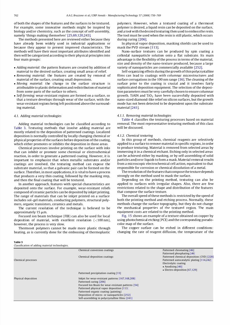
7/22/2019 Keynote Published
http://slidepdf.com/reader/full/keynote-published 13/20
of both the shapes of the features and the surfaces to be textured.
For example, some innovative methods might be inspired by
biology and/or chemistry, such as the concept of self-assembly,
namely ‘things making themselves’ [25,69,120,243].
The methods presented here are reviewed either because they
have already been widely used in industrial applications or
because they appear to present improved characteristics. The
methods will have their most important attributes identified and
then will be categorized according to their physical principles intofour main groups:
Adding material: the pattern features are created by addition of
material to the desired surface, creating small areas of relief. Removing material: the features are created by removal of
material of the surface, creating small depressions. Moving material: the change in the surface structure is
attributable to plastic deformation and redistribution of material
from some parts of the surface to others. Self-forming : wear-resistant regions are formed on a surface, so
that a texture develops through wear of the surface, with the
wear-resistant regions being left positioned above the surround-
ing material.
4.1. Adding material technologies
Adding material technologies can be classified according to
Table 3. Texturing methods that involve adding material are
mostly related to the deposition of patterned coatings. Localized
deposition is normally controlled by locally changing chemical or
physical properties of the surfaces before deposition of the coating,
which either promotes or inhibits the deposition in those areas.
Chemical processes involve printing on the surface with inks
that can inhibit or promote some chemical or electrochemical
reaction, in order to generate a patterned coating. However, it is
important to emphasize that when metallic substrates and/or
coatings are involved, the texturing method can expose the
substrate material, so that a galvanic pair can be formed on the
surface. Therefore, in most applications, it is vital to have a processthat produces a very thin coating, followed by the masking step,
and then the final coating that will be textured.
In another approach, features with special characteristics are
deposited onto the surface. For example, wear-resistant reliefs
composed of ceramic particles can be deposited by inkjet printing.
The range of materials that can be inkjet printed on a surface
includes sol–gel materials, conducting polymers, structural poly-
mers, organic transistors, ceramics and metals.
The current resolution of the technique is believed to be
approximately 15mm.
Focused ion beam technique (FIB) can also be used for local
deposition of material, with excellent resolution (<100 nm),
however, the process is very slow.
Thermoset polymers cannot be made more plastic throughheating, as is currently done for the embossing of thermoplastic
polymers. However, when a textured coating of a thermoset
polymer is desired, a liquid resin can be deposited on the surface,
and a tool with thedesired texturing then used to embossthe resin.
The tool must be used when the resin is still plastic, which occurs
during curing [206].
In physical vapor deposition, masking shields can be used to
mask the PVD stream [113].
Nano-surface textures can be produced by spin coating a
colloidal nanoparticle solution onto a flat substrate. Its mainadvantage is the flexibility of the process in terms of the material,
size and density of the nano-texture produced, because a large
variety of nanoparticles are commercially available [252].
Self-organizing effects during the growth of thin polycrystalline
films can lead to coatings with columnar microstructures and
surface corrugations in the 100 nm range [36]. The cleaning of the
surface prior to the coating is crucial and it involves fairly
sophisticated deposition equipment. The selection of the deposi-
tion parameters must be very carefully chosen to ensure columnar
growth. TiAlN and TiO2 have been successfully deposited with
nano-sized diamond-like relief on silicon surfaces, but the growth
mode has not been detected to be dependent upon the substrate
material [241].
4.1.1. Removing material technologies
Table 4 classifies the texturing processes based on material
removal. The most representative texturing methods of this class
will be discussed.
4.1.2. Chemical texturing
In this group of methods, chemical reagents are selectively
applied to a surface to remove material in specific regions, in order
to produce texturing. Material is removed from selected areas by
immersing it in a chemical etchant. Etching only in selected areas
can be achieved either by masking, or by self-assembling of solid
particles and/oror liquids to form a mask. Material removal results
from a microscopic electrochemical cell action, equivalent to that
responsible for corrosion or chemical dissolution of a metal.
The resolution of the features thatcompose the texture dependsstrongly on the method used to mask the surface.
Depending on the printing method, texturing can also be
applied to surfaces with irregular shapes. Also, there are few
restrictions related to the shape and distribution of the features
that compose the surface texture.
The overall speed of these methods is restricted by the speed of
both the printing method and etching process. Normally, these
methods change the surface topography, but they do not change
the mechanical properties of the textured region. The main
equipment costs are related to the printing method.
Fig. 15 shows an example of a texture obtained on copper by
using photochemical etching (PCE) and the corresponding pseudo-
color map of the surface.
The copper surface can be etched in different conditions:changing the rate of reagent diffusion, the temperature of the
Table 3
Classification of adding material technologies.
Chemical conversion coatings Patterned chromating [46]
Patterned phosphating [46]
Chemical deposition coatings Patterned chemical deposition (CVD) [228]
Chemical processes Patterned autocatalytic plating [114,242]
Electrolytic coating
Anodising [46]
Electro-deposition [67,129]
Patterned precipitation coating [13]
Physical deposition Inkjet for wear-resistant patterns [167,168,208]
Patterned curing [206]
Focused Ion Beam for wear-resistant patterns [54]Patterned physical vapor deposition [113]
Patterned organic coating (painting)
Deposition of micro- or nanoparticles [252]
Self-assembling in polycrystalline films [241]
A.A.G. Bruzzone et al. / CIRP Annals - Manufacturing Technology 57 (2008) 750–769762
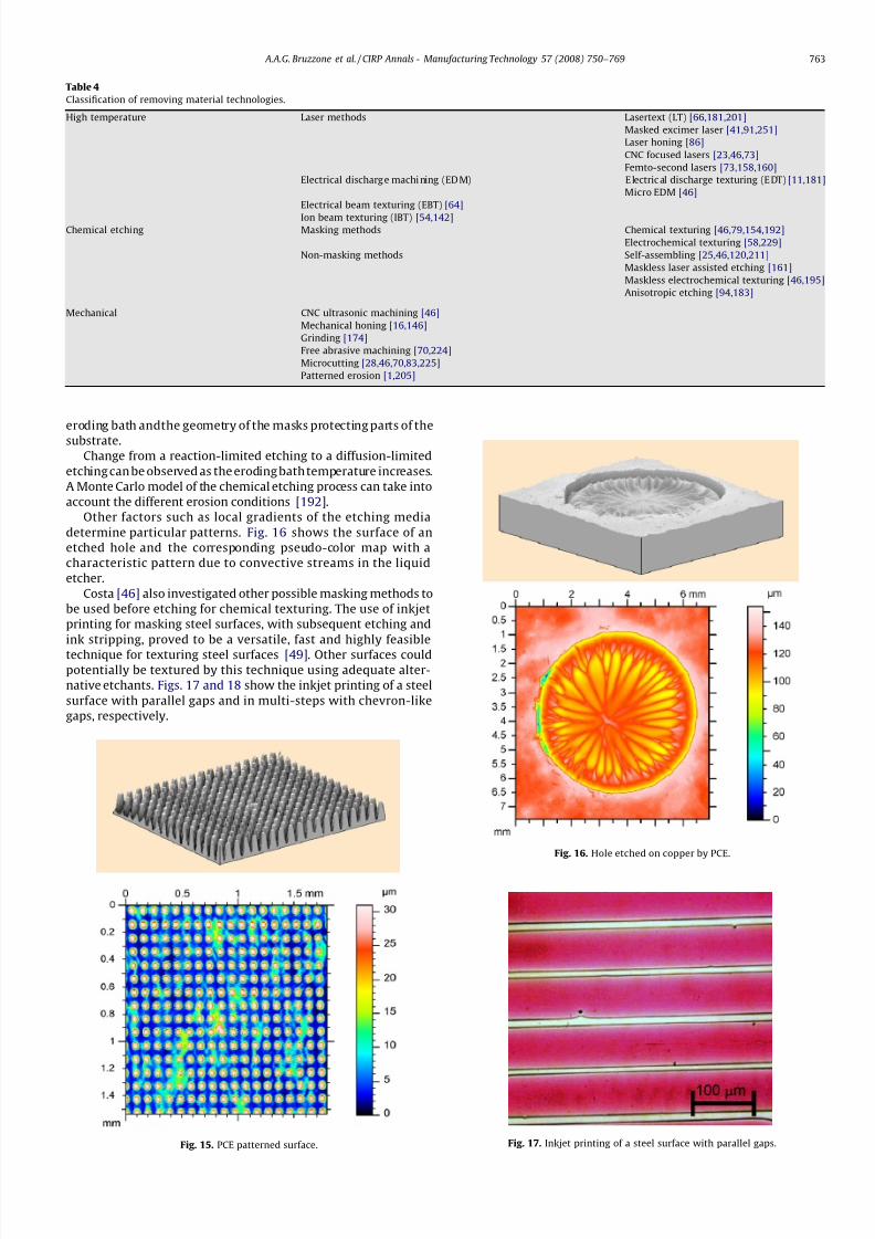
7/22/2019 Keynote Published
http://slidepdf.com/reader/full/keynote-published 14/20
eroding bath andthe geometry of the masks protecting parts of the
substrate.
Change from a reaction-limited etching to a diffusion-limited
etching can be observed as the eroding bath temperature increases.
A Monte Carlo model of the chemical etching process can take into
account the different erosion conditions [192].
Other factors such as local gradients of the etching media
determine particular patterns. Fig. 16 shows the surface of an
etched hole and the corresponding pseudo-color map with a
characteristic pattern due to convective streams in the liquid
etcher.
Costa [46] also investigated other possible masking methods to
be used before etching for chemical texturing. The use of inkjet
printing for masking steel surfaces, with subsequent etching and
ink stripping, proved to be a versatile, fast and highly feasible
technique for texturing steel surfaces [49]. Other surfaces couldpotentially be textured by this technique using adequate alter-
native etchants. Figs. 17 and 18 show the inkjet printing of a steel
surface with parallel gaps and in multi-steps with chevron-like
gaps, respectively.
Fig. 15. PCE patterned surface.
Fig. 16. Hole etched on copper by PCE.
Table 4
Classification of removing material technologies.
High temperature Laser methods Lasertext (LT) [66,181,201]
Masked excimer laser [41,91,251]
Laser honing [86]
CNC focused lasers [23,46,73]
Femto-second lasers [73,158,160]
Electrical discharg e machi ning (ED M) E lectric al discharge texturing (E DT) [11,181]
Micro EDM [46]
Electrical beam texturing (EBT) [64]
Ion beam texturing (IBT) [54,142]Chemical etching Masking methods Chemical texturing [46,79,154,192]
Electrochemical texturing [58,229]
Non-masking methods Self-assembling [25,46,120,211]
Maskless laser assisted etching [161]
Maskless electrochemical texturing [46,195]
Anisotropic etching [94,183]
Mechanical CNC ultrasonic machining [46]
Mechanical honing [16,146]
Grinding [174]
Free abrasive machining [70,224]
Microcutting [28,46,70,83,225]
Patterned erosion [1,205]
Fig. 17. Inkjet printing of a steel surface with parallel gaps.
A.A.G. Bruzzone et al. / CIRP Annals - Manufacturing Technology 57 (2008) 750–769 763
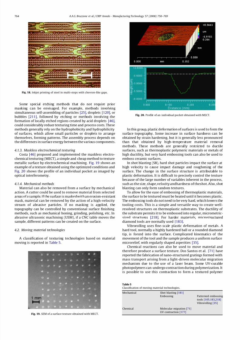
7/22/2019 Keynote Published
http://slidepdf.com/reader/full/keynote-published 15/20
Some special etching methods that do not require prior
masking can be envisaged. For example, methods involving
simultaneous self-assembling of particles [25], droplets [120], or
bubbles [211], followed by etching or methods involving the
formation of locally etched regions created by acid droplets [46],
could considerably reduce texturing time and process costs. These
methods generally rely on the hydrophobicity and hydrophilicity
of surfaces, which allow small particles or droplets to arrange
themselves, forming patterns. The assembly process depends on
the differences in surface energy between the various components.
4.1.3. Maskless electrochemical texturing
Costa [46] proposed and implemented the maskless electro-
chemical texturing (MECT), a simple and cheap method to texture
metallic surface by electrochemical machining. Fig. 19 shows an
example of a texture obtained using the optimized conditions and
Fig. 20 shows the profile of an individual pocket as imaged by
optical interferometry.
4.1.4. Mechanical methods
Material can also be removed from a surface by mechanical
action. A cutter could be used to remove material from selected
areas of a sample. If the surface is maskedwith an erosion-resistant
mask, material can be removed by the action of a high-velocity
stream of abrasive particles. If no masking is applied, the
topography can be controlled by conventional surface finishing
methods, such as mechanical honing, grinding, polishing, etc. In
abrasive ultrasonic machining (USM), if a CNC table moves the
sample, different patterns can be created on the surface.
4.2. Moving material technologies
A classification of texturing technologies based on materialmoving is reported in Table 5.
In this group, plastic deformation of surfaces is used to form the
surface topography. Some increase in surface hardness can be
obtained by strain hardening, but it is generally less pronounced
than that obtained by high-temperature material removal
methods. These methods are generally restricted to ductile
surfaces, such as thermoplastic polymeric materials or metals of
high ductility, but very hard embossing tools can also be used to
emboss ceramic surfaces.
In shot blasting (SB), hard shot particles impact the surface at
high velocity to cause impact damage and roughening of the
surface. The change in the surface structure is attributable to
plastic deformation. It is difficult to precisely control the texture
because of the large number of variables inherent in the process,such as the size, shape,velocity andhardness of theshot. Also, shot
blasting can only form random textures.
To allow for the ease of embossing of thermoplastic materials,
the surface to be textured must be heated until it becomes plastic.
The embossing tools do not need to be very hard, which lowers the
tooling costs. This is a simple and versatile way to create well-
resolved structures on thermoplastic substrates. The ductility of
the substrate permits it to be embossed into regular, micrometric-
sized structures [218]. For harder materials, microstructured
diamond tools are normally used [183].
Vibrorolling uses fine-scale plastic deformation of metals. A
hard tool, normally a highly hardened ball or a rounded diamond
tip, is forced into the surface. Complicated kinematics of the
movement of the tool and the sample produces a uniform surfacemicrorelief, with regularly shaped asperities [35].
Chemical reactions can also be used to move material and
therefore produce a surface texture. Dos Santos et al. [71] have
reported the fabrication of nano-structured gratings formed with
mass transport arising from a light-driven molecular migration
mechanism due to the use of a laser beam. Some UV-curable
photopolymers can undergo contraction during polymerization. It
is possible to use this contraction to form a textured polymer
Fig. 18. Inkjet printing of steel in multi-steps with chevron-like gaps.
Fig. 19. SEM of a surface texture obtained with MECT.
Fig. 20. Profile of an individual pocket obtained with MECT.
Table 5
Classification of moving material technologies.
Mechanical Shot blasting [181]
Embossing Patterned embossing
tools [105,183,218]
Vibrorolling [35]
Chemical Molecular migration [71]
UV contraction [177]
A.A.G. Bruzzone et al. / CIRP Annals - Manufacturing Technology 57 (2008) 750–769764
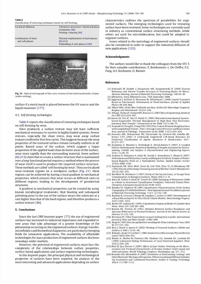
7/22/2019 Keynote Published
http://slidepdf.com/reader/full/keynote-published 16/20
surface if a metal mask is placed between the UV source and the
liquid monomer [177].
4.3. Self-forming technologies
Table 6 reports the classification of texturing techniques based
on self-forming by wear.
Once produced, a surface texture may not have sufficient
mechanical resistance to survive in highly loaded systems. Severe
stresses, especially the shear stress, may wear away surface
textures withinthe first few cycles. This happens because the wear
properties of the textured surface remain virtually uniform at all
points. Raised areas of the surface, which support a larger
proportion of the applied loads than do lower areas of the surface,wear more rapidly than the surrounding material. Some authors
[82,213] claim that to create a surface structure that is maintained
over a long functional period requires a method where the process
of wear itself is used to produce the required surface structure.
These methods are called ‘self-forming by wear’. They use localized
wear-resistant regions on a workpiece surface (Fig. 21); these
regions can be achieved by having a local gradient in mechanical
properties, which ensures that wear occurs at different rates in
different regions, leading to the development of geometrical
structures.
A gradient in mechanical properties can be created by using
known metallurgical treatments. Shot blasting and subsequent
polishing prior to the use of the surface wears the substrate at a
rate higher than that of the hard regions, and therefore produces asurface texture [46].
5. Conclusions
Since the last CIRP keynote paper [77] the use of engineered
surfaces has increased its industrial importance and expanded to
new areas that take advantage of a greater knowledge of the
phenomena occurring on the engineered surfaces. Energy transfer,
microfluidics and biomedical diagnostics are particularly emerging
fields for innovative applications, The availability of affordable
technologies for mass production of engineered surfaces discloses
nowadays wider markets.
However, the potential of engineered surfaces must face the
complexity of the relationships between surface properties,surface-based applications and surface engineering technologies.
In this keynote paper, the principal physical and technological
properties of surfaces have been reported. An analysis of the
most interesting and advanced applications depending on surface
characteristics outlines the spectrum of possibilities for engi-
neered surfaces. The emerging technologies used for texturing
surface have been reviewed. Some technologies are currently used
in industry as conventional surface structuring methods, while
others are used for microfabrication, but could be adapted to
engineer surfaces.
Issues related to the metrology of engineered surfaces should
also be considered in order to support the industrial diffusion of
new applications [125].
Acknowledgments
The authors would like to thank the colleagues from the STC S
for their valuable contributions: E. Brinksmeier, L. De Chiffre, F.Z.
Fang, A.S. Korhonen, O. Riemer.
References
[1] Achtsnick M, Drabbe J, Hoogstrate AM, Karpuchewski B (2004) ErosionBehaviour and Pattern Transfer Accuracy of Protecting Masks for Micro-Abrasive Blasting. Journal of Materials Processing Technology 149:43–49.
[2] Affymetrix, www.Affymetrix.com, 15th September 2008.
[3] Aggarwal J, Kotlicki A, Mossman M, Whitehead L (2006) Liquid TransportBased on Electrostatic Deformation of Fluid Interfaces. Journal of AppliedPhysics 99:104–904.
[4] Albert WAJ (1838) Uber Treibseile am Harz. Archive fur Miner alogie Geogno sieBergbau und Hu ttenkunde 10:215–234.
[5] AltingL, KimuraF, HansenHN, Bissacco G (2003)MicroEngineering. Annals of the CIRP 52(2):635–657.
[6] Amon CH, Yao SC, Wu CF, Hsieh CC (2005) Microelectromechanical System-based Evaporative Thermal Management of High Heat Flux Electronics.
Journal of Heat Transfer—Transactions of the ASME 127(1):66–75.[7] Aramaki H,ChengHS, Chung YW(1993)The Contact Between RoughSurfaces
with Longitudinal Texture—Part I. Average ContactPressure and Real ContactArea. Journal of Tribology—Transactions of the ASME 115(3):419–424.
[8] Aravanis AM, Debusschere BD, Chruscinski AJ, Gilchrist KH, Kobilka BK,Kovacs GTA (2001) A Genetically Engineered Cell-based Biosensor forFunctional Classification of Agents. Biosensors & Bioelectronics 16(7–8):571–577.
[9] Arzpeyma A, Bhaseen S, Dolatabadi A, Wood-Adams P (2007) A CoupledElectro-Hydrodynamic Numerical Modeling of Droplet Actuation by Electro-wetting. Colloids and Surfaces A Physicochemical and Engineering Aspects323(1–3):28–35.
[10] Asakura H, Nakajima A, Sakai M, Suzuki S, Kameshima Y, Okada K (2007)Deformationand Motionby Gravity andMagneticField ofa Droplet of Water-based Magnetic Fluid on a Hydrophobic Surface. Applied Surface Science253(6):3098–3102.
[11] Aspinwall DK, Wise MLH, Stout KJ, Goh THA, Zhao FL, El-Menshawy MF(1992) Electrical Discharge Texturing. Journal of Machine Tools & Manufacture32(12):183–193.
[12] Barthlott W, Neinhuis C (1997) Purity of the Sacred Lotus, or Escape fromContamination in Biological Surfaces. Planta 202(1):1–8.
[13] Bartz M, Terfort A, Knoll W, Tremel W (2000) Stamping of Monomeric SAMsas a Route to Structured Crystallisation Templates: Patterned Titania Films.Chemistry-A European Journal 6(22):4149–4153.
[14] Batalha GF, Stipkovic M (2001) Quantitative Characterization of the SurfaceTopography of Cold RolledSheets—New Approachesand Possibilities. Journalof Materials Processing Technology 113(1–3):732–738.
[15] Baudoin R, Griscom L, Monge M, Legallais C, Leclerc E (2007) Development of
a Renal Microchip for In Vitro Distal Tubule Models. Biotechnology Progress23(5):1245–1253.[16] Becker EP, Ludema KC (1999) A Qualitative Empirical Model of Cylinder Bore
Wear. Wear 225–229:387–404.[17] Bennet HE, Porteus JO (1961) Relation Between Surface Roughness and
Specular Reflectance at Normal Incidence. Journal of the Optical Society of America 51:123–129.
[18] Berenson PJ (1962) Experiments on pool boiling heat transfer. International Journal of Heat and Mass Transfer 5:985–999.
[19] Berge B (1993) Electrocapillariteet mouillagede films isolantspar l’eau. CRAS III 317:157–163.
[20] Bico J, Thiele U, Quere D (2002) Wetting of Textured Surfaces. Colloids andSurfaces A 206(1–3):41–46.
[21] BinnigG, Quate CF,GerberC (1986) AtomicForceMicroscope.Physical ReviewLetters 56(9):930–933.
[22] Blatter A, Maillat M, Pimenov SM, Shafeeev GA, Simakin AV, Loubnin EN(1999) Lubricated Sliding Performance of Laser-Patterned Sapphire. Wear 232(2):226–230.
[23] Blau PJ, Qu J, Riester L (2005) Effects of Laser Surface Texturing on the Micro-
structure and Frictional Characteristics of Zirconia Surfaces Under Liquid andSolid Lubrication. World Tribology Congress, Washington. pp. 311–312.
[24] Bouzakis KD, Michailidis N (2007) Deviations in Determining Coatings’ andOtherMaterials’ MechanicalProperties, WhenConsidering Different IndenterTip Geometries and Calibration Procedures. Surface & Coatings Technology202(4–7):1108–1112.
Table 6
Classification of texturing techniques based on self-forming.
Localized d if fusion C hemical con vers ion + th erm ochemical
treatments [46]
Printing + heating [46]
Combination of hard
and soft phases
Thermal implantation of hard phases
[82,213]
Embedding of soft phases [100]
Fig. 21. Optical micrograph of the cross-section of two hard martensitic stripes
(white etching).
A.A.G. Bruzzone et al. / CIRP Annals - Manufacturing Technology 57 (2008) 750–769 765
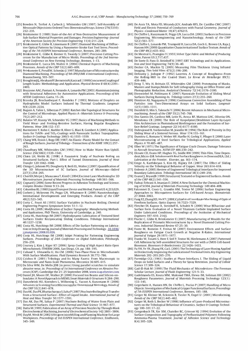
7/22/2019 Keynote Published
http://slidepdf.com/reader/full/keynote-published 17/20
[25] Bowden N, Terfort A, Carbeck J, Whitesides GM (1997) Self-Assembly of Mesoscale Objectsinto Ordered Two-DimensionalArrays. Science 276(5310):232–235.
[26] Brinksmeier E (1989) State-of-the-Art of Non-Destructive Measurement of Sub-Surface Material Properties and Damages. Precision Engineering—Journalof the American Society for Precision Engineering 11(4):211–224.
[27] Brinksmeier E, Glabe R, Lunemann B (2007) Diamond Machining of Diffrac-tive Optical Patterns by Using a Nanometer-Stroke Fast Tool Servo. Proceed-ings of the 7th EUSPEN International Conference , Bremen, 285–289.
[28] Brinksmeier E, Glabe R, Riemer O, Twardy S (2007) Precision Cutting Pro-cesses for the Manufacture of Micro Molds. Proceedings of the 2nd Interna-
tional Conference on New Forming Technology, Bremen, 1–13.[29] Brinksmeier E, Lucca DA, Walter A (2004) Chemical Aspects of MachiningProcesses. Annals of the CIRP 53(2):685–699.
[30] Brinksmeier E, PreußW, Schmutz J (1997)Manufacture of MicrostructuresbyDiamond Machining. Proceedings of 9th IPES/UME 4 International Conference,Braunschweig, 503–507.
[31] BroughtonJQ, AbrahamFF,BernsteinN,KaxirasE (1999)ConcurrentCouplingof Length Scales: Methodology and Application. Physical Review B 60(4):2391–2403.
[32] Bruzzone AAG, Pantani A, Ferrando A, Lonardo PM (2003) Aluminium Joiningwith Structural Adhesives for Automotive Applications. Proceedings of 6th
AITEM Conference, Gaeta, 15–26.[33] Brzoska JB, Brochardwyart F, Rondelez F (1993) Motions of Droplets on
Hydrophobic Model Surfaces Induced by Thermal Gradients. Langmuir 9(8):2220–2224.
[34] Buguin A, Talini L, Silberzan P (2002) Ratchet-like Topological Structures forthe Control of Microdrops. Applied Physics A—Materials Science & Processing 75(2):207–212.
[35] Bulatov VP, Krasny VA, Schneider YG (1997) Basics of Machining Methods to
Yield Wear- and Fretting-Resistive Surfaces, Having Regular RoughnessPatterns. Wear 208:132–137.
[36] Burmeister F, Kohn C, Kuebler R, Kleer G, Blasi B, Gombert A (2005) Applica-tions for TiAlN- and TiO2-Coatings with Nanoscale Surface Topographies.Surface & Coatings Technology 200(5–6):1555–1559.
[37] Chang WR, Etsion I, Bogy DB (1987) An Elastic–Plastic Model for the Contactof Rough Surfaces. Journal of Tribology—Transactions of the ASME 109(2):257–263.
[38] Chaudhury MK, Whitesides GM (1992) How to Make Water Run Uphill.Science 256(5063):1539–1541.
[39] Chien LH, Webb RL (1998) A Parametric Study of Nucleate Boiling onStructured Surfaces. Part I. Effect of Tunnel Dimensions. Journal of Heat Transfer 120:1042–1048.
[40] Chinga G, Johnsen PO, Dougherty R, Berli EL, Walter J (2007) Quantification of the 3D Microstructure of SC Surfaces. Journal of Microscopy—Oxford227(3):254–265.
[41] Choi KH,Meijer J, Masuzawa T, KimD (2004)Excimer Laser Machiningfor 3DMicrostructure. Journal of Materials Processing Technology 149:561–566.
[42] Cognard J (2006) Some Recent Progress in Adhesion Technology and Science.Comptes Rendus Chimie 9:13–24.
[43] Columbus RL (1980)LiquidTransport Device and Method, PatentUS 4,233,029.[44] Corbett J, Mckeown PA, Peggs GN, Whatmore R (2000) Nanotechnology:
International Developments and Emerging Products. Annals of the CIRP 49(2):523–545.
[45] Corty C, Foust AS (1955) Surface Variables in Nucleate Boiling. ChemicalEngineering Progress Symposium Series 51:1–12.
[46] Costa HL (2005) Modification of Surface Topography: Manufacturing Methodsand Applications, PhD Thesis, University of Cambridge, p. 240.
[47] Costa HL, Hutchings IM (2007) Hydrodynamic Lubrication of Textured SteelSurfaces Under Reciprocating Sliding Conditions. Tribology International40:1227–1238.
[48] Costa HL, Hutchings IM (2008) Effects of Die Surface Patterning on Lubrica-tion in Strip Drawing. Journal of Materials Processing and Technology . 10.1016/
j.jmatprotec.2008.03.026.[49] Costa HL, Hutchings IM (2008) Inkjet Printing for Patterning Engineering
Surfaces. Proceedings of 24th Conference on Digital Fabrication, Pittsburgh,256–259.
[50] Coursey J, Kim J, Kiger KT (2006) Spray Cooling of High Aspect Ratio OpenMicrochannels. ITHERM 2006, San Diego, CA. pp. 188–195.
[51] Cubaud T, Ulmanella U, Ho CM (2006) Two-Phase Flow in MicrochannelsWith Surface Modifications. Fluid Dynamics Research 38:772–786.
[52] Czichos H (2001) Tribology and Its Many Facets: From Macroscopic toMicroscopic and Nano-Scale Phenomena. Meccanica 36:605–615.
[53] Da Silva WM, De Mello JDB (in press) Using parallel scratches to simulateabrasive wear, in: Proceedings of 1st International Conference on Abrasive Pro-cesses (ICAP), Cambridge the 21–25 September 2008, www.icap.elsevier.com.
[54] Daniel JH, Moore DF, Walker JF (2000) Focused Ion Beams and Silicon-on-Insulator:A NovelApproach to MEMS. Smart Materials & Structures 9:284–290.
[55] Danzebrink HU, Koenders L, Wilkening G, Yacoot A, Kunzmann H (2006)Advances in Scanning ForceMicroscopyfor Dimensional Metrology. Annals of the CIRP 55(2):841–878.
[56] DasAK, DasPK,Bhattacharyya S,Saha P (2007)NucleateBoilingHeat Transferfrom a Structured Surface—Effect of Liquid Intake. International Journal of Heat and Mass Transfer 50:1577–1591.
[57] Das AK, Das PK, Sahaa P (2007) Nucleate Boiling of Water from Plain andStructured Surfaces. Experimental Thermal and Fluid Science 31:967–977.
[58] Datta M (1995) Fabrication of an Array of Precision Nozzles by Through-MaskElectrochemical Machining. Journal of Electrochemical Society 142:3801–3806.
[59] DayM, Weck M (2002)UltraprecisionMilling andPlanning Machine forLargeWorkpieces. Proceedings of 3rd EUSPEN International Conference, Eindhoven,345–349.
[60] De Assis TA, Mota FD, Miranda JGV, Andrade RFS, De Castilho CMC (2007)Field and Electric Potential of Conductors with Fractal Geometry. Journal of Physics—Condensed Matter 19(47):476215.
[61] De Chiffre L, Kunzmann H, Peggs GN, Lucca DA (2003) Surfaces in PrecisionEngineering, Microengineering and Nanotechnology. Annals of the CIRP 52(2):561–577.
[62] De Chiffre L, Lonardo PM, Trumpold H, Lucca DA, Goch G, Brown CA, Raja J,Hansen HN (2000) Quantitative Characterisationof Surface Texture. Annals of the CIRP 49(2):635–652.
[63] De Mestral G, Pramgins Y (1955) Velvet Type Fabric and Method of Producing Same, Patent US 2,717,437.
[64] De Soete D, Pans D, Steinhoff K (1997) EBT Technology and its Applications.Iron and Steel Engineering 74(9):36–40.[65] Decker CA, Mackin TJ (2005) Measuring Film Thickness Using Infrared
Imaging. Thin Solid Films 473(2):196–200.[66] Defourny J, Jodogne P (1992) Lasertex, A Concept of Roughness—From
the Rolling-Mill to the Coated Sheet. La Revue de Metallurgie 89(5):439–446.
[67] Deng T, Wu H, Brittain ST, Whitesides GM (2000) Prototyping of Masks,Masters and Stamps/Molds for Soft Lithography Using an Office Printer andPhotographic Reduction. Analytical Chemistry 72(14):3176–3180.
[68] Dienwiebel M, Pohlmann K (2007) Nanoscale Evolution of Sliding MetalSurfaces During Running-In. Tribology Letters 27(3):255–260.
[69] Dimitrov AS, Nagayama K (1996) Continuous Convective Assembling of FineParticles into Two-Dimensional Arrays on Solid Surfaces. Langmuir 12(5):1303–1311.
[70] Dornfeld D, Min S, Takeuchi Y (2006) Recent Advances in Mechanical Micro-machining. Annals of the CIRP 55(2):745–768.
[71] Dos Santos DS, Cardoso MR, Leite FL, Aroca RF, Mattoso LHC, Oliveira ON,Mendonca CR (2006) The Role of Azopolymer/Dendrimer Layer-by-Layer
Film Architecture in Photoinduced Birefringence and the Formation of Sur-face-Relief Gratings. Langmuir 22(14):6177–6180.
[72] Dubrujeaud B, Vardavoulias M, Jeandin M (1994) The Role of Porosity in DrySliding Wear of a Sintered Ferrous. Wear 174:155–161.
[73] Dumitru G, Romano V, Weber HP, Haefke H, Gerbig Y, Pfluger E (2000) LaserMicrostructuring of Steel Surfaces for Tribological Applications. AppliedPhysics A 70:485–487.
[74] Elber W (1971) The Significance of Fatigue Crack Closure, Damage Tolerancein Aircraft Structures. ASTM STP 486:230–242.
[75] Elcoate CD, Evans HP, Hughes TG, Snidle RW (1999) Thin Film, Time Depen-dent,Micro-EHL Solutionswith Real Surface Roughness.in DowsonDEA, (Ed.)Lubrication at the Frontier . Elsevier, pp. 163–174.
[76] Emge A, Karthikeyan S, Kim HJ, Rigney DA (2007) The Effect of SlidingVelocity on the Tribological Behavior of Copper. Wear 263:614–618.
[77] Erdemir A (2005) Review of Engineered Tribological Interfaces for ImprovedBoundary Lubrication. Tribology International 38(3):249–256.
[78] EvansCJ, BryanJB (1999) Structured, Textured or Engineered Surfaces. Annalsof the CIRP 48(2):541–556.
[79] Fadeai-Tehrani A, Imanian E (2004) A New Etchant for the Chemical Machin-ing of St304. Journal of Materials Processing Technology 149:404–408.
[80] Falconnet D, Csucs G, Grandin HM, Textor M (2006) Surface EngineeringApproaches to Micropattern Surfaces for Cell-based Arrays. Biomaterials27:3044–3063.
[81] Fang FZ,ZhangXD, HuXT (2008)CylindricalCoordinate Machining of OpticalFreeform Surfaces. Optics Express 16:7323–7329.
[82] Fletcher DI, Kapoor A, Steinhoff K, Schuleit N (2000) Wear BEhaviour andSurface form Evaluation of a Novel Titanium Carbide Implanted SurfaceUnder Lubricated Conditions. Proceedings of the Institution of MechanicalEngineers 597–610. 214/J.
[83] Flucke C, Glabe R, Brinksmeier E (2007) Manufacturing of Moulds for theReplication of Prismatic Microstructures by a Novel Diamond Cutting Pro-cess. Industrial Diamond Review 67:25–30.
[84] Fonte M, Romeiro F, Freitas M (2007) Environment Effects and SurfaceRoughness on Fatigue Crack Growth at Negative R-Ratios. International
Journal of Fatigue 29:1971–1977.[85] Franks W, Tosatti S, Heer F, Seif P, Textor M, Hierlemann A (2007) Patterned
Cell Adhesion by Self-assembled Structures for use with a CMOS Cell-based
Biosensor. Biosensors & Bioelectronics 22:1426–1433.[86] Fu YH, Ye YX, Zhang YK, Cai L (2001) The Technology of Laser Honing Applied
in Distinctively Improving the Lubricationof Frictional Units. Key Engineering Materials 202–203:265–270.
[87] Furmidge CGL (1961) Studies at Phase Interfaces. I. The Sliding of LiquidDrops on Solid Surfaces and a Theory for Spray Retention. Journal of ColloidScience 17:309–324.
[88] Gad-El-Hak M (1999) The Fluid Mechanics of Microdevices—The FreemanScholar Lecture. Journal of Fluids Engineering 121:5–33.
[89] Gadelmawla ES, Koura MM, Maksoud TMA, Elewa IM, Soliman HH (2002)Roughness Parameters. Journal of Materials Processing Technology 123(1):133–145.
[90] Gegeckaite A, Hansen HN, De Chiffre L, Pocius P (2007) Handling of MicroObjects: Investigation of Mechanical Gripper FunctionalSurfaces.Proceedingsof 7th EUSPEN International Conference, Bremen, 185–188.
[91] Geiger M, Kleiner M, Eckstein R, Tiesler N, Engel U (2001) Microforming. Annals of the CIRP 50(2):445–462.
[92] Geiger M, Roth S, Becker W (1998) Influence of Laser-Produced Microstruc-tures on the Tribological Behaviour of Ceramics. Surface & Coatings Technol-
ogy 100–101:17–22.[93] Gengenbach TR, Xie XM, Chatelier RC, Griesser HJ (1994) Evolution of the
Surface-Composition and Topography of Perfluorinated Polymers FollowingAmmonia-Plasma Treatment. Journal of Adhesion Science and Technology8(4):305–328.
A.A.G. Bruzzone et al. / CIRP Annals - Manufacturing Technology 57 (2008) 750–769766
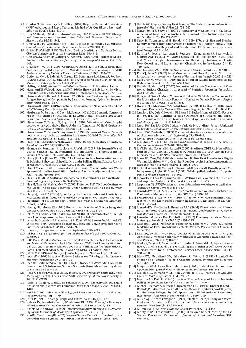
7/22/2019 Keynote Published
http://slidepdf.com/reader/full/keynote-published 18/20
[94] Gordon N, Starosvetsky D, Ein-Eli Y (2005) Negative Potential Dissolution(NPD)-Advanced and Rapid Texturing Method of As-Cut Silicon. Electrochi-mica Acta 50(27):5313–5321.
[95] Gray SA,Kusel JK,ShafferK, ShubinYS, Stenger DA,Pancrazio JJ (2001)Designand Demonstration of an Automated Cell-based Biosensor. Biosensors & Bioelectronics 16:535–542.
[96] Greenwood JA, Williamson JPB (1966) Contact of Nominally Flat Surfaces.Proceedings of the Royal Society of London Series A 295:300–319.
[97] Griffith P, WallisJD (1960)The Role of Surface Conditions in Nucleate Boiling.Chemical Engineering Progress Symposium Series 56:49–63.
[98] Gross PG, Kartalov EP, Schererc A, Weiner LP (2007) Applications of Micro-
fluidics for Neuronal Studies. Journal of the Neurological Sciences 252:135–143.[99] Grzesik W, Wanat T (2005) Comparative Assessment of Surface Roughness
Produced by Hard Machining with Mixed Ceramic Tools Including 2D and 3DAnalysis. Journal of Materials Processing Technology 169(3):364–371.
[100] Gutierrez-Mora F, Erdemir A, Goretta KC, Dominguez-Rodriguez A, Routbort JL (2005) Dry and Oil-Lubricated Sliding Wear of Si3N4 and Si3N4/BN FibrousMonoliths. Tribology Letters 18(2):231–237.
[101] Halling J (1976) Introduction to Tribology. Wykeham Publications, London.[102] Hamilton DB, Walowit JA,AllenCM (1966) A Theoryof Lubrication by Micro-
Irregularities. Journal of Basic Engineering—Transactions of the ASME 177–185.[103] Hammersley G, Hackel LA, Harris F (2000) Surface Prestressing to Improve
Fatigue Strength of Components by Laser Shot Peening. Optics and Lasers inEngineering 34:327–337.
[104] Hermann K (2007) CIRP International Comparison on Nanoindentation. CIRP STC-S Meeting , Paris, January 26, .
[105] Heuberger M, Feldman K, Zach M, Spencer ND (2002) Dynamic Control of Friction via Surface Structuring. in Dowson D, (Ed.) Boundary and MixedLubrication: Science and Applications. Elsevier, pp. 67–73.
[106] Higashiyama Y, Yamada T, Sugimoto T (1999) Vibration of Water DropletLocated on a Hydrophobic Sheet Under the Tangential AC Field. ConferenceRec. IAS 1999 Annual Meeting , Phoenix, 1825–1830.
[107] Higashiyama Y, Yanase S, Sugimoto T (1998) Behavior of Water DropletsLocated on a Hydrophobic Insulating Plate under DC Field. ConferenceRec. IAS 1998 Annual Meeting , St. Louis, 1808–1813.
[108] Hocken RJ, Chakraborty N, Brown C (2005) Optical Metrology of Surfaces. Annals of the CIRP 54(2):705–719.
[109] HolmbergK, RonkainenH, LaukkanenA, WallinK (2007)Frictionand Wear of Coated Surfaces—Scales, Modelling and Simulation of Tribomechanisms.Surface & Coatings Technology 202(4–7):1034–1049.
[110] Horng JH, Lin JF, Lee KY (1994) The Effect of Surface Irregularities on theTribological Bahaviour of Steel Rollers Under Rolling-Sliding Contact. Journalof Tribology—Transactions of the ASME 116:209–218.
[111] HsiehCC, Yao SC (2006) Evaporative Heat Transfer Characteristics of a WaterSpray on Micro-Structured Silicon Surfaces. International Journal of Heat andMass Transfer 49:962–974.
[112] Hu G, Li D (2007) Multiscale Phenomena in Microfluidics and Nanofluidics.Chemical Engineering Science 62:3443–3454.
[113] Hua M, Tam HY, Ma HY, Mok CK (2006) Patterned PVD TiN Spot Coatings onM2 Steel: Tribological Behaviors Under Different Sliding Speeds. Wear 260(11–12):1153–1165.
[114] Hupp SJ, Hart DP (2005) Quantifying the Effect of Lubricant Elasticity onMicrotextured Surfaces. World Tribology Congress III , Washington, 483–484.
[115] Hutchings IM (1992) Tribology–Friction and Wear of Engineering Materials.Arnold, London.
[116] Hwang UP, Moran KF (1981) Boiling Heat Transfer of Silicon IntegratedCircuits Chip Mounted on a Substrate. ASME HTD 20:53–59.
[117] Ichimura K, Sang-KennO, Nakagawa M (2000) Light-drivenMotion of Liquidson a Photoresponsive Surface. Science 288:1624–1626.
[118] Ikawa N, Donaldson RR, Komanduri R, Konig W, Mckeown PA, Moriwaki T,Stowers IF(1991)UltraprecisionMetalCutting, ThePast,The Present andTheFuture. Annals of the CIRP 40(2):584–597.
[119] Infineon, http://www.infineon.com, September 15th 2008.[120] Ishibashi K (1993)Methods for Treating the Surface of a Solid Body , Patent US
5,198,073.[121] ISO14577, Metallic Materials—Instrumented Indentation Test for Hardness
and Materials Parameters, Part 1. Test Method, 2002, Part 2. Verification andCalibrationof Testing Machines, 2002,Part 3. Calibrationof Reference Blocks,Part 4. Test Method for Metallic and Non-Metallic Coatings, 2007.
[122] Jakob M (1949) Heat Transfer . John Wiley & Sons, New York. pp. 636–638.[123] Jeng YR (1996) Impact of Plateau Surfaces on Tribological Performance.
Tribology Transactions 39(2):354–361.[124] Jeon NL, Dertinger SKW, Chiu DT, Choi IS, Stroock AD, Whitesides GM (2000)
Generation of Solution and Surface Gradients Using Microfluidic Systems.Langmuir 16:8311–8316.
[125] Jiang X, Scott PJ, Whitehouse DJ, Blunt L (2007) Paradigm Shifts in SurfaceMetrology. Part II. The Current Shift. Proceedings of the Royal Society A463:2071–2099.
[126] Jones TB, Gunji M, Washizu M, Feldman MJ (2001) Dielectrophoretic LiquidActuation and Nanodroplet Formation. Journal of Applied Physics 89:1441–1448.
[127] Jost HP (1966) Lubrication (Tribology)—A Report on the Present Position andIndustry’s Needs. . pp. 1–79.
[128] Jost HP (1990) Tribology–Origin and Future. Wear 136(1):1–17.[129] Kalvala PR, Beesabathina DP, Wiedemann KE (1999) Process for Forming a
Wear-Resistant Coating that Minimizes Debris, US Patent 5,955,145.[130] Kaneta M, Nishikawa H (1999) Experimental Study on Micro-EHL. Proceed-
ings of the Institution of Mechanical Engineers 371–381. 213/J.[131] KimDE, ChaKH, SungIH (2002) Design of SurfaceMicro-Structures forFriction
Control in Micro-Systems Applications. Annals of the CIRP 51(1):495–498.
[132] Kim J (2007) Spray Cooling Heat Transfer: The State of the Art. International Journal of Heat and Fluid Flow 28:753–767.
[133] Kruger-Sehm R, Seewig J (2007) Uncertainty of Measurement in the Deter-mination of Roughness Parameters Using Contact Stylus Instruments. Tech-nisches Messen 74(10):529–537.
[134] Kubo H, Takamatsuand H, Honda H (1999) Effects of Size and NumberDensity of Micro-Reentrant Cavities on Boiling Heat Transfer from a SiliconChip Immersed in Degassed and Gas-dissolved FC-72. Journal of EnhancedHeat Transfer 6:151–160.
[135] Kuisma R, Pesonen-Leinonen E, Redsven I, Kymalainen HR, Saarikoski I,Sjoberg AM, Hautala M (2005) Utilization of Profilometry, SEM, AFM
and Contact Angle Measurements in Describing Surfaces of PlasticFloor Coverings and Explaining their Cleanability. Surface Science 584(1):119–125.
[136] Kun LC, Czikk AM (1969) Surface for Boiling Liquids, Patent US 3,454,081.[137] Kuo CJ, Peles Y (2007) Local Measurement of Flow Boiling in Structured
Microchannels. International Journal of Heatand MassTransfer 50:4513–4526.[138] Kurihari HM, Myers JE (1960) Effects of Superheat and Roughness on the
Boiling Coefficients. AIChE Journal 6:83–91.[139] Kuroda M, Marrow TJ (2007) Preparation of Fatigue Specimens with Con-
trolled Surface Characteristics. Journal of Materials Processing Technology203(1–3):396–403.
[140] Kuzuya M, Sawa T, Mouri M, Kondo SI, Takai O (2003) Plasma Technique forthe Fabrication of a Durable Functional Surface on Organic Polymers. Surface& Coating Technologies 169:587–591.
[141] Kwong VH, Mossman MA, Whitehead LA (2004) Control of Reflectanceof Liquid Droplets by Means of Electrowetting. Applied Optics 43:808–813.
[142] Langford RM, Dale G, Hopkins PJ, Ewen PJS, Petford-Long AK (2002) FocusedIon Beam Micromachining of Three-Dimensional Structures and Three-Dimensional Reconstruction to Assess their Shape. Journal of Micromechanics
and Microengineering 12:111–114.[143] Leech PW, Lee RA (2006) Optically Variable Micro-Mirror Arrays Fabricated
by Graytone Lithography. Microelectronic Engineering 83:351–356.[144] Leech PW, Zeidlerb H (2003) Microrelief Structures for Anti-Counterfeiting
Applications. Microelectronic Engineering 65:439–446.[145] Levi L (1968) Applied Optics. John Wiley & Sons, New York.[146] Li L, Chai DM (2001)The Research andApplicationof HoningTechnology.Key
Engineering Materials 202–203:385–388.[147] Li YR,Pereira G,Kasrai M,NortonPR (2007)Studieson ZDDP Anti-WearFilms
Formed Under Different Conditions by XANES Spectroscopy, Atomic ForceMicroscopy and 31P NMR. Tribology Letters 28(3):319–328.
[148] Liang HS, Yang WJ (1998) Nucleate Pool Boiling Heat Transfer in a HighlyWetting Liquid on Micro-Graphite Fiber Composite Surfaces. International
Journal of Heat and Mass Transfer 41:1993–2000.[149] Linke H, Aleman BJ, Melling LD, Taormina MJ, Francis MJ, Dow-Hygelund CC,
Narayanan V, Taylor RP, Stout A (2006) Self-Propelled Leidenfrost Droplets.Physical Review Letters 96:154–502.
[150] Lipowsky R, Lenz P, Swain PS (2000) Wetting and Dewetting of Structuredand Imprinted Surfaces. Colloids and Surfaces A 161:3–22.
[151] Lippmann G (1875) Relation entre les phenomenes electriques et capillaires. Annales de Chimie Physics 5:494–549.
[152] Lonardo PM (1974) Measurement of Smooth Surface Roughness by Means of Photometric Methods. Annals of the CIRP 23(1):189–190.
[153] Lonardo PM, Bruzzone AAG (1989) Influence of Surface Roughness Para-meters on the Mechanical Strength in Metal Gluing. Annals of the CIRP 38(1):571–574.
[154] Lonardo PM, De Chiffre L, Bruzzone AAG (2004) Characterisation of Func-tional Surfaces. Proceedings of 2nd International Conference on Tribology inManufacturing Processes, Nyborg, Denmark, 39–62.
[155] Lonardo PM, Lucca DA, De Chiffre L (2002) Emerging Trends in SurfaceMetrology. Annals of the CIRP 51(2):701–723.
[156] Luan BQ, Hyun S, Molinari JF, Bernstein N, Robbins MO (2006) MultiscaleModeling of Two-Dimensional Contacts. Physical Review Letters E 74(4 Pt2):046710.
[157] Luan BQ, Robbins MO (2006) Contact of Single Asperities with VaryingAdhesion: Comparing Continuum Mechanics to Atomistic Simulations. Phy-sical Review E 74(2 Pt 2):026111.
[158] Mailis S, Zergioti I, Koundourakis G, Ikiades A, Patentalaki A, Papakonstanti-nou P, Vainos N, Fotakis C (1999) Etching and Printing of Diffractive OpticalMicrostructures by a Femtosecond Excimer Laser. Applied Optics 38(11):2303–2308.
[159] Mate CM, Mcclelland GM, Erlandsson R, Chiang S (1987) Atomic-ScaleFriction of a Tungsten Tip on a Graphite Surface. Physical Review Letters59:1942–1945.
[160] Meijer J (2004) Laser Beam Machining (LBM), State of the Art and NewOpportunities. Journal of Materials Processing Technology 149:2–17.
[161] Melcher RL, Romankiw LT, Von Gutfeld RJ (1983) Method for MasklessChemical Machining , Patent US 4,379,022.
[162] Messina AD, Park EL (1981) Effects of Precise Arrays of Pits on NucleateBoiling. International Journal of Heat Transfer 24:141–145.
[163] Michel B, Bernard A, Bietsche A, Delamarche E, Geissler M, Juncker D, Kind H,Renault JP,Rothuizen H, SchmidH, Schmidt-Winkel P, Stutz R, Wolf H (2001)Printing Meets Lithography: Soft Approaches to High-Resolution Patterning.IBM Journal of Research & Development 45(3):697–719.
[164] Miller WJ, Gebhart B, Wright NT (1990) Effects of Boiling History on a Micro-Configured Surface in a Dielectric Liquid. International Communications in
Heat and Mass Transfer 17:389–398.[165] Milton RM (1968) Heat Exchange System, Patent US 3,384,154.[166] Mordyuk BN, Prokopenko GI (2007) Ultrasonic Impact Peening for the
Surface Properties’ Management. Journal of Sound and Vibration 308:855–866.
A.A.G. Bruzzone et al. / CIRP Annals - Manufacturing Technology 57 (2008) 750–769 767
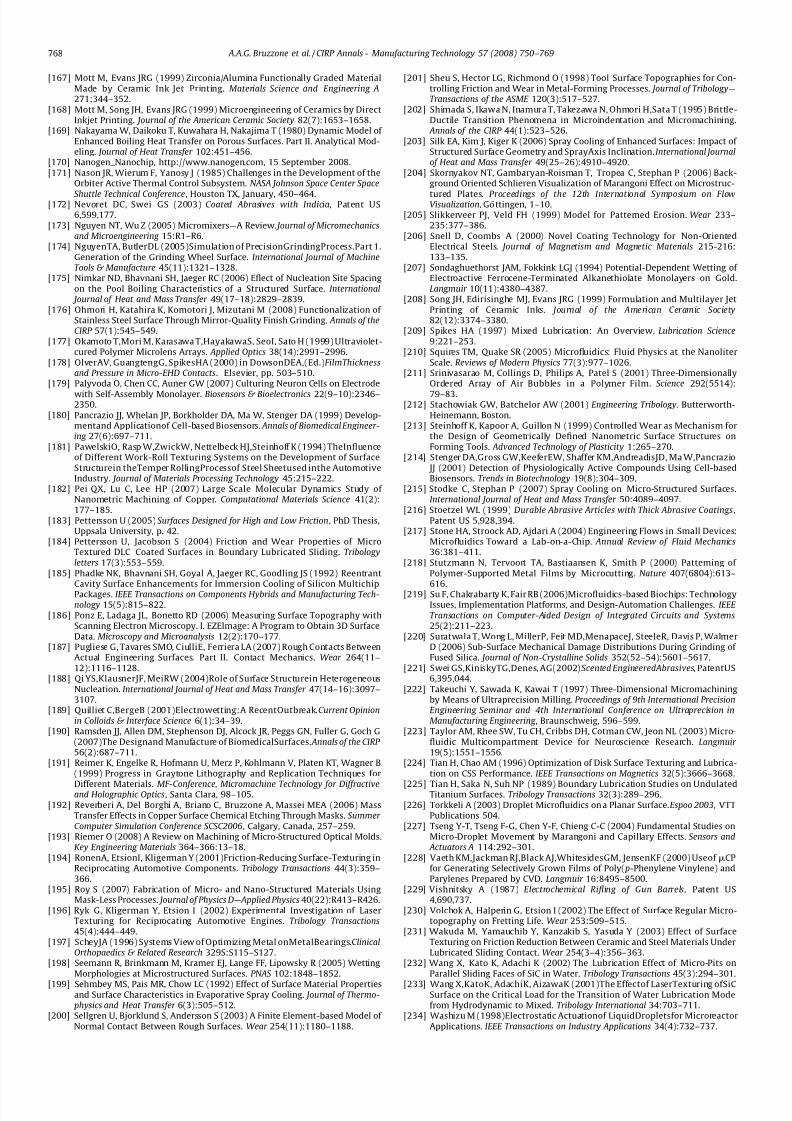
7/22/2019 Keynote Published
http://slidepdf.com/reader/full/keynote-published 19/20
[167] Mott M, Evans JRG (1999) Zirconia/Alumina Functionally Graded MaterialMade by Ceramic Ink Jet Printing. Materials Science and Engineering A271:344–352.
[168] Mott M, Song JH, Evans JRG (1999) Microengineering of Ceramics by DirectInkjet Printing. Journal of the American Ceramic Society 82(7):1653–1658.
[169] Nakayama W, Daikoku T, Kuwahara H, Nakajima T (1980) Dynamic Model of Enhanced Boiling Heat Transfer on Porous Surfaces. Part II. Analytical Mod-eling. Journal of Heat Transfer 102:451–456.
[170] Nanogen_Nanochip, http://www.nanogen.com, 15 September 2008.[171] Nason JR, Wierum F, Yanosy J (1985) Challenges in the Development of the
Orbiter Active Thermal Control Subsystem. NASA Johnson Space Center Space
Shuttle Technical Conference, Houston TX, January, 450–464.[172] Nevoret DC, Swei GS (2003) Coated Abrasives with Indicia, Patent US6,599,177.
[173] Nguyen NT, Wu Z (2005) Micromixers—A Review.Journal of Micromechanicsand Microengineering 15:R1–R6.
[174] NguyenTA, ButlerDL (2005)Simulation of PrecisionGrindingProcess.Part 1.Generation of the Grinding Wheel Surface. International Journal of MachineTools & Manufacture 45(11):1321–1328.
[175] Nimkar ND, Bhavnani SH, Jaeger RC (2006) Eflect of Nucleation Site Spacingon the Pool Boiling Characteristics of a Structured Surface. International
Journal of Heat and Mass Transfer 49(17–18):2829–2839.[176] Ohmori H, Katahira K, Komotori J, Mizutani M (2008) Functionalization of
Stainless Steel Surface Through Mirror-Quality Finish Grinding. Annals of theCIRP 57(1):545–549.
[177] Okamoto T,Mori M, Karasawa T,HayakawaS, SeoI, Sato H (1999) Ultraviolet-cured Polymer Microlens Arrays. Applied Optics 38(14):2991–2996.
[178] OlverAV, GuangtengG, SpikesHA (2000) in DowsonDEA,(Ed.)FilmThicknessand Pressure in Micro-EHD Contacts. Elsevier, pp. 503–510.
[179] Palyvoda O, Chen CC, Auner GW (2007) Culturing Neuron Cells on Electrode
with Self-Assembly Monolayer. Biosensors & Bioelectronics 22(9–10):2346–2350.
[180] Pancrazio JJ, Whelan JP, Borkholder DA, Ma W, Stenger DA (1999) Develop-mentand Applicationof Cell-based Biosensors. Annals of Biomedical Engineer-ing 27(6):697–711.
[181] PawelskiO, Rasp W,ZwickW, Nettelbeck HJ,Steinhoff K (1994) TheInfluenceof Different Work-Roll Texturing Systems on the Development of SurfaceStructurein theTemper RollingProcessof Steel Sheetused inthe AutomotiveIndustry. Journal of Materials Processing Technology 45:215–222.
[182] Pei QX, Lu C, Lee HP (2007) Large Scale Molecular Dynamics Study of Nanometric Machining of Copper. Computational Materials Science 41(2):177–185.
[183] Pettersson U (2005) Surfaces Designed for High and Low Friction, PhD Thesis,Uppsala University, p. 42.
[184] Pettersson U, Jacobson S (2004) Friction and Wear Properties of MicroTextured DLC Coated Surfaces in Boundary Lubricated Sliding. Tribologyletters 17(3):553–559.
[185] Phadke NK, Bhavnani SH, Goyal A, Jaeger RC, Goodling JS (1992) ReentrantCavity Surface Enhancements for Immersion Cooling of Silicon MultichipPackages. IEEE Transactions on Components Hybrids and Manufacturing Tech-nology 15(5):815–822.
[186] Ponz E, Ladaga JL, Bonetto RD (2006) Measuring Surface Topography withScanning Electron Microscopy. I. EZElmage: A Program to Obtain 3D SurfaceData. Microscopy and Microanalysis 12(2):170–177.
[187] Pugliese G, Tavares SMO, CiulliE, Ferriera LA (2007) Rough Contacts BetweenActual Engineering Surfaces. Part II. Contact Mechanics. Wear 264(11–12):1116–1128.
[188] Qi YS,KlausnerJF, MeiRW (2004)Role of Surface Structurein HeterogeneousNucleation. International Journal of Heat and Mass Transfer 47(14–16):3097–3107.
[189] Quilliet C,BergeB (2001)Electrowetting:A RecentOutbreak.Current Opinionin Colloids & Interface Science 6(1):34–39.
[190] Ramsden JJ, Allen DM, Stephenson DJ, Alcock JR, Peggs GN, Fuller G, Goch G(2007)The Designand Manufacture of BiomedicalSurfaces. Annals of the CIRP 56(2):687–711.
[191] Reimer K, Engelke R, Hofmann U, Merz P, Kohlmann V, Platen KT, Wagner B(1999) Progress in Graytone Lithography and Replication Techniques for
Different Materials. MF-Conference, Micromachine Technology for Diffractiveand Holographic Optics, Santa Clara, 98–105.
[192] Reverberi A, Del Borghi A, Briano C, Bruzzone A, Massei MEA (2006) MassTransfer Effects in Copper Surface Chemical Etching Through Masks. Summer Computer Simulation Conference SCSC2006 , Calgary, Canada, 257–259.
[193] Riemer O (2008) A Review on Machining of Micro-Structured Optical Molds.Key Engineering Materials 364–366:13–18.
[194] RonenA, EtsionI, Kligerman Y (2001)Friction-Reducing Surface-Texturing inReciprocating Automotive Components. Tribology Transactions 44(3):359–366.
[195] Roy S (2007) Fabrication of Micro- and Nano-Structured Materials UsingMask-Less Processes. Journal of Physics D—Applied Physics 40(22):R413–R426.
[196] Ryk G, Kligerman Y, Etsion I (2002) Experimental Investigation of LaserTexturing for Reciprocating Automotive Engines. Tribology Transactions45(4):444–449.
[197] ScheyJA (1996) Systems View of Optimizing Metal onMetalBearings.ClinicalOrthopaedics & Related Research 329S:S115–S127.
[198] Seemann R, Brinkmann M, Kramer EJ, Lange FF, Lipowsky R (2005) WettingMorphologies at Microstructured Surfaces. PNAS 102:1848–1852.
[199] Sehmbey MS, Pais MR, Chow LC (1992) Effect of Surface Material Propertiesand Surface Characteristics in Evaporative Spray Cooling. Journal of Thermo-
physics and Heat Transfer 6(3):505–512.[200] Sellgren U, Bjorklund S, Andersson S (2003) A Finite Element-based Model of
Normal Contact Between Rough Surfaces. Wear 254(11):1180–1188.
[201] Sheu S, Hector LG, Richmond O (1998) Tool Surface Topographies for Con-trolling Friction and Wear in Metal-Forming Processes. Journal of Tribology—Transactions of the ASME 120(3):517–527.
[202] Shimada S, Ikawa N, Inamura T, Takezawa N, Ohmori H,Sata T (1995) Brittle-Ductile Transition Phenomena in Microindentation and Micromachining.
Annals of the CIRP 44(1):523–526.[203] Silk EA, Kim J, Kiger K (2006) Spray Cooling of Enhanced Surfaces: Impact of
Structured Surface Geometry and SprayAxis Inclination. International Journalof Heat and Mass Transfer 49(25–26):4910–4920.
[204] Skornyakov NT, Gambaryan-Roisman T, Tropea C, Stephan P (2006) Back-ground Oriented Schlieren Visualization of Marangoni Effect on Microstruc-
tured Plates. Proceedings of the 12th International Symposium on FlowVisualization, Gottingen, 1–10.[205] Slikkerveer PJ, Veld FH (1999) Model for Patterned Erosion. Wear 233–
235:377–386.[206] Snell D, Coombs A (2000) Novel Coating Technology for Non-Oriented
Electrical Steels. Journal of Magnetism and Magnetic Materials 215-216:133–135.
[207] Sondaghuethorst JAM, Fokkink LGJ (1994) Potential-Dependent Wetting of Electroactive Ferrocene-Terminated Alkanethiolate Monolayers on Gold.Langmuir 10(11):4380–4387.
[208] Song JH, Edirisinghe MJ, Evans JRG (1999) Formulation and Multilayer JetPrinting of Ceramic Inks. Journal of the American Ceramic Society82(12):3374–3380.
[209] Spikes HA (1997) Mixed Lubrication: An Overview. Lubrication Science9:221–253.
[210] Squires TM, Quake SR (2005) Microfluidics: Fluid Physics at the NanoliterScale. Reviews of Modern Physics 77(3):977–1026.
[211] Srinivasarao M, Collings D, Philips A, Patel S (2001) Three-DimensionallyOrdered Array of Air Bubbles in a Polymer Film. Science 292(5514):
79–83.[212] Stachowiak GW, Batchelor AW (2001) Engineering Tribology. Butterworth-
Heinemann, Boston.[213] Steinhoff K, Kapoor A, Guillon N (1999) Controlled Wear as Mechanism for
the Design of Geometrically Defined Nanometric Surface Structures onForming Tools. Advanced Technology of Plasticity 1:265–270.
[214] Stenger DA,Gross GW,KeeferEW, Shaffer KM,AndreadisJD, Ma W,Pancrazio JJ (2001) Detection of Physiologically Active Compounds Using Cell-basedBiosensors. Trends in Biotechnology 19(8):304–309.
[215] Stodke C, Stephan P (2007) Spray Cooling on Micro-Structured Surfaces.International Journal of Heat and Mass Transfer 50:4089–4097.
[216] Stoetzel WL (1999) Durable Abrasive Articles with Thick Abrasive Coatings,Patent US 5,928,394.
[217] Stone HA, Stroock AD, Ajdari A (2004) Engineering Flows in Small Devices:Microfluidics Toward a Lab-on-a-Chip. Annual Review of Fluid Mechanics36:381–411.
[218] Stutzmann N, Tervoort TA, Bastiaansen K, Smith P (2000) Patterning of Polymer-Supported Metal Films by Microcutting. Nature 407(6804):613–616.
[219] Su F, Chakrabarty K, Fair RB (2006)Microfluidics-based Biochips: TechnologyIssues, Implementation Platforms, and Design-Automation Challenges. IEEE Transactions on Computer-Aided Design of Integrated Circuits and Systems25(2):211–223.
[220] Suratwala T, Wong L, MillerP, Feit MD,MenapaceJ, SteeleR, Davis P, WalmerD (2006) Sub-Surface Mechanical Damage Distributions During Grinding of Fused Silica. Journal of Non-Crystalline Solids 352(52–54):5601–5617.
[221] Swei GS,KiniskyTG,Denes, AG(2002)Scented EngineeredAbrasives, PatentUS6,395,044.
[222] Takeuchi Y, Sawada K, Kawai T (1997) Three-Dimensional Micromachiningby Means of Ultraprecision Milling. Proceedings of 9th International PrecisionEngineering Seminar and 4th International Conference on Ultraprecision inManufacturing Engineering , Braunschweig, 596–599.
[223] Taylor AM, Rhee SW, Tu CH, Cribbs DH, Cotman CW, Jeon NL (2003) Micro-fluidic Multicompartment Device for Neuroscience Research. Langmuir 19(5):1551–1556.
[224] Tian H, Chao AM (1996) Optimization of Disk Surface Texturing and Lubrica-tion on CSS Performance. IEEE Transactions on Magnetics 32(5):3666–3668.
[225] Tian H, Saka N, Suh NP (1989) Boundary Lubrication Studies on UndulatedTitanium Surfaces. Tribology Transactions 32(3):289–296.
[226] Torkkeli A (2003) Droplet Microfluidics on a Planar Surface.Espoo 2003, VTTPublications 504.
[227] Tseng Y-T, Tseng F-G, Chen Y-F, Chieng C-C (2004) Fundamental Studies onMicro-Droplet Movement by Marangoni and Capillary Effects. Sensors and
Actuators A 114:292–301.[228] Vaeth KM,Jackman RJ,Black AJ,WhitesidesGM, JensenKF (2000) Useof mCP
for Generating Selectively Grown Films of Poly( p-Phenylene Vinylene) andParylenes Prepared by CVD. Langmuir 16:8495–8500.
[229] Vishnitsky A (1987) Electrochemical Rifling of Gun Barrels, Patent US4,690,737.
[230] Volchok A, Halperin G, Etsion I (2002) The Effect of Surface Regular Micro-topography on Fretting Life. Wear 253:509–515.
[231] Wakuda M, Yamauchib Y, Kanzakib S, Yasuda Y (2003) Effect of SurfaceTexturing on Friction Reduction Between Ceramic and Steel Materials UnderLubricated Sliding Contact. Wear 254(3–4):356–363.
[232] Wang X, Kato K, Adachi K (2002) The Lubrication Effect of Micro-Pits onParallel Sliding Faces of SiC in Water. Tribology Transactions 45(3):294–301.
[233] Wang X,KatoK, AdachiK, AizawaK (2001)The Effectof LaserTexturing ofSiCSurface on the Critical Load for the Transition of Water Lubrication Modefrom Hydrodynamic to Mixed. Tribology International 34:703–711.
[234] Washizu M (1998)Electrostatic Actuationof LiquidDropletsfor MicroreactorApplications. IEEE Transactions on Industry Applications 34(4):732–737.
A.A.G. Bruzzone et al. / CIRP Annals - Manufacturing Technology 57 (2008) 750–769768

7/22/2019 Keynote Published
http://slidepdf.com/reader/full/keynote-published 20/20
[235] Webb RL (2004) Kern Lecture Award Paper: Odyssey of the Enhanced BoilingSurface. Journal of Heat Transfer 126(6):1051–1059.
[236] Wei P, Swei GS, Yang WP (2001) Production of Layered Engineered AbrasiveSurfaces, Patent US 6,293,980.
[237] Whitehouse DJ, Bowen DK, Venkatesh VC, Lonardo PM, Brown CA (1994)Gloss and Surface Topography. Annals of the CIRP 43(2):541–549.
[238] Williams JA (1994) Engineering Tribology. Oxford University Press, Oxford.[239] Wink T, Vanzuilen SJ, Bult A, Vanbennekom WP (1997) Self-Assembled
Monolayers for Biosensors. Analyst 122(4):R43–R50.[240] Wu XF, Shi GQ (2005) Fabrication of a Lotus-Like Micro–Nanoscale
Binary Structured Surface and Wettability Modulation from Super-
hydrophilic to Superhydrophobic. Nanotechnology 16(10):2056–2060.[241] Wuhrer R, Yeung WY (2004) Grain Refinement with Increasing MagnetronDischarge Power in Sputter Deposition of Nanostructured Titanium Alumi-nium Nitride Coatings. Scripta Materialia 50(6):813–818.
[242] Xia Y, Whitesides GM (1998) Soft Lithography.Angewandte Chemie-Interna-tional Edition 37(5):550–575.
[243] Xu S, Li M, Mitov Z, Kumacheva E (2003) Surface Textures Induced byConvection in Thin Films of Polymeric and Polymerizable Fluids. Progressin Organic Coatings 48(2–4):227–235.
[244] Yahata N (1987) Effect of Lapping on the Fatigue-Strength of a Hardened13Cr–0.34C Stainless Steel. Wear 115(3):337–348.
[245] YahataN, InukaiT, Hayama F (1982)Effect of Surface Workingon theFatigue-Strength and Wear of a Hardened 13%Cr Stainless Steel. Wear 80(1):89–100.
[246] Yang C, Tartaglino U, Persson BNJ (2006) Influence of Surface Roughness onSuperhydrophobicity. PRL 97:116103.
[247] Yang JJ, Liao YS, Chen CF (2007) Fabrication of Long Hexagonal Micro-LensArray by Applying Gray-Scale Lithography in Micro-Replication Process.Optics Communications 270(2):433–440.
[248] Yoshino M,Matsumura T,UmeharaN, Akagami Y,Aravindan S,Ohno T (2006)Engineering Surface and Development of a New DNA Micro Array Chip. Wear 260(3):274–286.
[249] Yum JH, Yoo SJ, Kim SS, Kim DY, Sung YE (2003) Anti-Reflection Layer Using
Nano Structured Surface Relief Gratings for Solar Cell. ECS 203rd meeting , May,Paris, .[250] Zhao YW, Maietta DM, Chang L (2000) An Asperity Microcontact Model
Incorporating the Transition from Elastic Deformation to Fully Plastic Flow. Journal of Tribology—Transactions of the ASME 122(1):86–93.
[251] Zimmer K, Braun A, Bigl F (2000) Combination of Different ProcessingMethods for the Fabrication of 3D Polymer Structures by Excimer LaserMachining. Applied Surface Science 154–155:601–604.
[252] Zou M, Cai L, Wang H (2006) Adhesion and Friction Studies of a Nano-Textured Surface Produced by Spin Coating of Colloidal Silica NanoparticleSolution. Tribology Letters 21(1):25–30.
A.A.G. Bruzzone et al. / CIRP Annals - Manufacturing Technology 57 (2008) 750–769 769