keyestudio CNC Shield v4.0 3-axis Stepper Motor Driver...
19
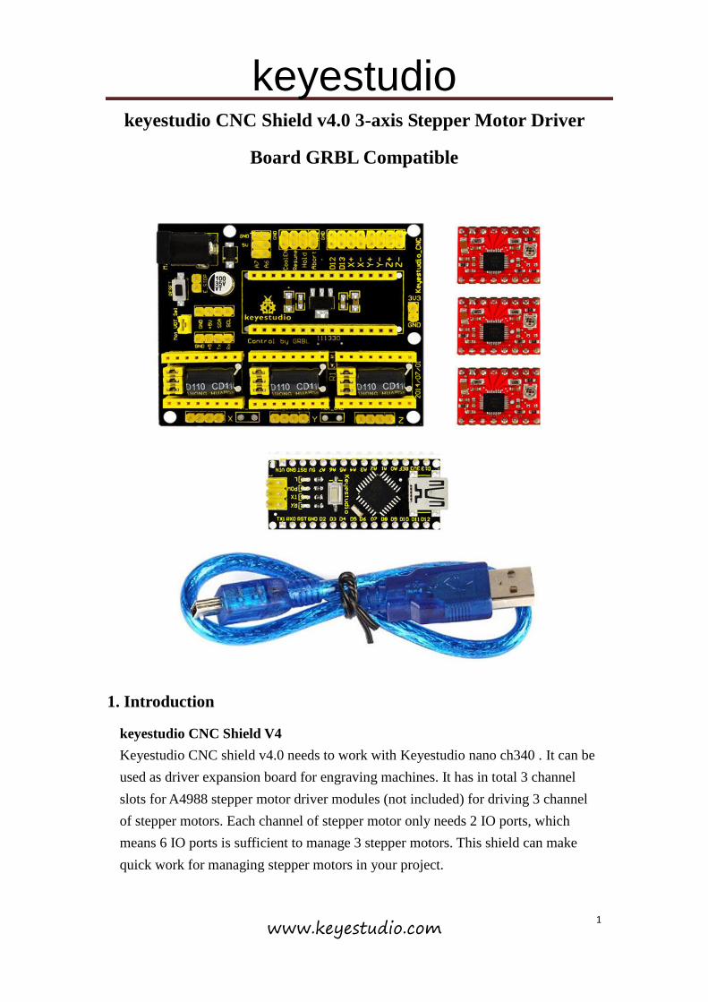
keyestudio www.keyestudio.com 1 keyestudio CNC Shield v4.0 3-axis Stepper Motor Driver Board GRBL Compatible 1. Introduction keyestudio CNC Shield V4 Keyestudio CNC shield v4.0 needs to work with Keyestudio nano ch340 . It can be used as driver expansion board for engraving machines. It has in total 3 channel slots for A4988 stepper motor driver modules (not included) for driving 3 channel of stepper motors. Each channel of stepper motor only needs 2 IO ports, which means 6 IO ports is sufficient to manage 3 stepper motors. This shield can make quick work for managing stepper motors in your project.
Transcript of keyestudio CNC Shield v4.0 3-axis Stepper Motor Driver...
keyestudio
www.keyestudio.com 1
keyestudio CNC Shield v4.0 3-axis Stepper Motor Driver
Board GRBL Compatible
1. Introduction
keyestudio CNC Shield V4
Keyestudio CNC shield v4.0 needs to work with Keyestudio nano ch340 . It can be
used as driver expansion board for engraving machines. It has in total 3 channel
slots for A4988 stepper motor driver modules (not included) for driving 3 channel
of stepper motors. Each channel of stepper motor only needs 2 IO ports, which
means 6 IO ports is sufficient to manage 3 stepper motors. This shield can make
quick work for managing stepper motors in your project.

keyestudio
www.keyestudio.com 2
keyestudio nano ch340
keyestudio nano ch340 controller is a small, complete board based on the
ATmega328. It’s a open source Simple I/O platform with 12 Digital I/O Pins (of
which 6 provide PWM output), 8 Analog Input Pins, pin 0 (RX) and 1 (TX) used to
receive (RX) and transmit (TX) TTL serial data, a Mini-B USB connection, an
ICSP header and a reset button.
2. Specification
1. 3-axis stepper motor driver
2. Compatible with micro-drive laser engraving machine, three-axis CNC engraving
machine.
3. 2A can be controlled within the two-phase four-wire stepper motor.
4. Released the digital IO interface, easy to connect to other modules, such as
ENDSTOP.
5. Released the I2C interface, you can connect to the LCD I2C or other I2C module.
6. Power DC5V interface, 7.5-12V voltage input.
7. GRBL compatible
8. Working with arduino nano.
3. Kit List
1x keyestudio CNC Shield v4.0
1x keyestudio nano ch340
3x A4988 Driver
1x USB Cable
4. Connection Diagram

keyestudio
www.keyestudio.com 3
5. Install Driver Software and Development Environment Software IDE
(1)Install Diver Software
A. Connect the main board with computer, and then right click “Computer” to enter “Device
Manage”.
B. Double click “Other devices”, appearing “USB2.0-Serial”.

keyestudio
www.keyestudio.com 4
Then, right click “USB2.0-Serial” and select “Update Driver Software” to install driver
software.

keyestudio
www.keyestudio.com 5
After that, select “Browse my computer for driver software” to find the file.
Browse to search for driver software.
After your driver software updated, click “Close” to finish.

keyestudio
www.keyestudio.com 6
C. Finally, installation is done, and double click “Ports”in “Device Manager”, you can see
“USB Serial Port(COM3)”.
(2) Install development environment software IDE
Double click arduino-1.5.6-r2-windows to start.
Select “I Agree”to accept license agreement.

keyestudio
www.keyestudio.com 7
Select components to install and click “Next”.
Click “Browse” and select another folder. Click “Install” to start the installation.

keyestudio
www.keyestudio.com 8
Finally, wait for a few minutes to finish.
6. Using Method
(1)Test Main Board
First, write below code in IDE to test whether main board, shield and three motors
work normally.
Explanation
1. If you properly reduce the value 800 in delayMicroseconds(800) to increase the
frequency of input PWM signal, you can increase the rotation speed of stepper motor.
The change of value cannot be too much or the motor will stop moving.

keyestudio
www.keyestudio.com 9
2. Rotate the knob on A4988, you can adjust the output current of the motors to
change the torque.
Code:
#define EN 8 // stepper motor enable, low level effective
#define X_DIR 5 //X axis, stepper motor direction control
#define Y_DIR 6 //y axis, stepper motor direction control
#define Z_DIR 7 //zaxis, stepper motor direction control
#define X_STP 2 //x axis, stepper motor control
#define Y_STP 3 //y axis, stepper motor control
#define Z_STP 4 //z axis, stepper motor control
/*
// Function: step -control the direction and number of steps of the stepper motor
// Parameter: dir -direction control, dirPin corresponds to DIR pin, stepperPin
correspomds to
step pin, steps is the number of steps.
// no return value
*/
void step(boolean dir, byte dirPin, byte stepperPin, int steps)
{
digitalWrite(dirPin, dir);
delay(50);
for (int i = 0; i < steps; i++) {
digitalWrite(stepperPin, HIGH);
delayMicroseconds(800);
digitalWrite(stepperPin, LOW);
delayMicroseconds(800);
}
}
void setup(){// set the IO pins for the stepper motors as output
pinMode(X_DIR, OUTPUT); pinMode(X_STP, OUTPUT);
pinMode(Y_DIR, OUTPUT); pinMode(Y_STP, OUTPUT);
pinMode(Z_DIR, OUTPUT); pinMode(Z_STP, OUTPUT);
pinMode(EN, OUTPUT);
digitalWrite(EN, LOW);
keyestudio
www.keyestudio.com 10
}
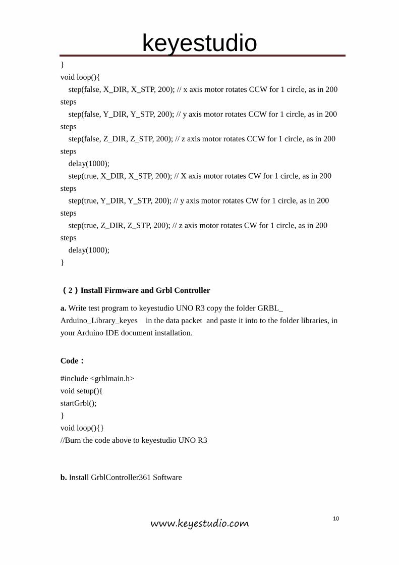
void loop(){
step(false, X_DIR, X_STP, 200); // x axis motor rotates CCW for 1 circle, as in 200
steps
step(false, Y_DIR, Y_STP, 200); // y axis motor rotates CCW for 1 circle, as in 200
steps
step(false, Z_DIR, Z_STP, 200); // z axis motor rotates CCW for 1 circle, as in 200
steps
delay(1000);
step(true, X_DIR, X_STP, 200); // X axis motor rotates CW for 1 circle, as in 200
steps
step(true, Y_DIR, Y_STP, 200); // y axis motor rotates CW for 1 circle, as in 200
steps
step(true, Z_DIR, Z_STP, 200); // z axis motor rotates CW for 1 circle, as in 200
steps
delay(1000);
}
(2)Install Firmware and Grbl Controller
a. Write test program to keyestudio UNO R3 copy the folder GRBL_
Arduino_Library_keyes in the data packet and paste it into to the folder libraries, in
your Arduino IDE document installation.
Code:
#include <grblmain.h>
void setup(){
startGrbl();
}
void loop(){}
//Burn the code above to keyestudio UNO R3
b. Install GrblController361 Software

keyestudio
www.keyestudio.com 11
Grbl Controller is a piece of software which is used to send GCode to CNC Machines.
Run Grbl Controller361 Setup in your installation packet, the interface below will
come out:
Click Next to continue.
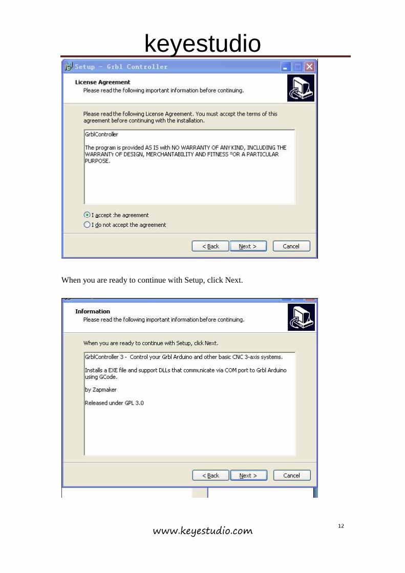
For a license agreement, please check I accept the agreement and click Next.
keyestudio
www.keyestudio.com 12
When you are ready to continue with Setup, click Next.
keyestudio
www.keyestudio.com 13
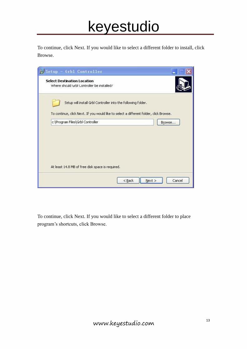
To continue, click Next. If you would like to select a different folder to install, click
Browse.
To continue, click Next. If you would like to select a different folder to place
program’s shortcuts, click Browse.

keyestudio
www.keyestudio.com 14
Select the additional tasks you would like Setup to perform while installing Grbl
Controller, then click Next.

keyestudio
www.keyestudio.com 15
Click Install to continue with the installation.
Click Next.

keyestudio
www.keyestudio.com 16
At last, click ”Finish” to finish the installation.

keyestudio
www.keyestudio.com 17
c. Test G-Code on Grbl Controller
Power the main board using a USB cable and connect correctly all your external
devices, then run Grbl Controller.
Choose Port name the same as IDE COM port and click “Open” to open the series
port, connecting CNC Machines with computer.

keyestudio
www.keyestudio.com 18
After opening the series port, the “Open” button change into “Close/Reset” and get
red!
At this time you can click the X axis、Y axis、Z axis as shown in below diagram to
adjust the motion direction of motors.
Now, it is time to have a try! Click ”Choose file” to choose one G-Code file named cn.
to test in the data packet for a beginner, and the interface will come out:

keyestudio
www.keyestudio.com 19
Click “Begin” , and you can see how the motors move on coordinates.
6. Reference
Arduino IDE Download
https://www.arduino.cc/en/Main/Donate
GRBL_Arduino_Library_keyes (Firmware) Download
http://www.keyestudio.com/files/index/download/id/1490772971/
Driver Download
http://www.keyestudio.com/files/index/download/id/1490772969/
G-Code for Testing Download
http://www.keyestudio.com/files/index/download/id/1490772970/
Grbl Controller361 Setup Download
http://www.keyestudio.com/files/index/download/id/1490774336/