KEPCO’s Drone Technology - World Bank Group
27
2020. 9. 9 Joon-Young Park KEPCO Research Institute Korea Electric Power Corporation KEPCO’s Drone Technology WBG Korea Office Webinar on post-COVID-19 Green Innovation
Transcript of KEPCO’s Drone Technology - World Bank Group

2020. 9. 9
Joon-Young Park
KEPCO Research Institute
Korea Electric Power Corporation
KEPCO’s Drone Technology
WBG Korea Office Webinar on post-COVID-19 Green Innovation

2
Introduction

3
Outline of Our Drone Project
① ② ③
(’16.9~’20.8)

GCS
Operator
Automatic Inspection
Drone System
on Autopilot Flight
4
Overall Drone Operation Scheme
Detailed
Inspection
Patrol
Surveillance
Vegetation
Encroachment
Monitoring
Industrial
Area
Salt Damage
Area
Sea • River
Crossing Area
Area with a
Long Span
Flatland
(Farmland)
Mountainous
Area
Gimbal
Operator
Thermal
OpticalZoom
Deep Learning
Auto-tracking
Camera
Gimbal

5
Contents
• Automatic Drone Inspection System
- Detailed Inspection, Patrol Surveillance
• 3D LiDAR-equipped Drone
- Line Sag Estimation, Vegetation Encroachment Monitoring
• Auto-tracking Camera Gimbal
• Hydrogen Fuel Cell Drone for BVLOS Flight

6
Motivation
• One could argue that controlling a rotary UAV under a 500m span
with a 250m line of sight is prone to errors and hazards. (On airborne
inspections: aircraft and crews, Newsletter of Albatroz Engineering, ’14)
☞Due to large scale of power transmission lines in their height and span,
drones should fly on autopilot along a planned path.

7
Task Environment
• Due to large scale of power transmission lines in their height and span,
drones should fly on autopilot along a planned path.
• However, a drone’s geomagnetic sensor indispensable for autopilot can
be adversely affected by strong magnetic field from power lines– Crash!
※ Credit of Magnetic Field :
380kV in Saudi Arabia (ICNIR 2003)

Task Environment
• To verify magnetic field interference,
we flew a drone vertically, starting from
40 meters away from the center of
345kV power lines toward the center at
intervals of 5 meters.
• We confirmed that magnetic field
interference occurs within 15 meters
from the center of 345kV power lines.
15m 10m 5m 0m
Drone
Compass Error
8

Task Environment
• At 12 meters from the center of 345kV
power lines, we measured magnetic field
strength by flying a drone vertically.
- Variation ±20% from Earth’s 500mG
9
15m 10m 5m 0m
Drone

Safe Flight Distance
10
• To avoid such magnetic field interference and GPS signal loss, we
determined safe flight distances based on the field tests as follows:
= 30 meters for 154 & 345kV power lines
= 45 meters for 765kV power linesSafe Flight Distance
7m 8m Safe Margin 15m
Safe Flight Distance for 345kV
Magnetic Field Interference Zone

11
Automatic Drone Inspection System
Way
Points
Safe Flight
Distance 30~45m
4K Zoom Thermal※ Task Environment Analysis
• Magnetic Field Interference(☞ Compass Sensor Error)
• Steel Tower Structure(☞ GPS Signal Distortion)
KEPCO Ground Control Station- Compatible with DJI A3(’17), Pixhawk 4(’19)
GPS Coordinate
Measuring Device
(w/ Correction Algorithm)

13
Pilot Application Results
Test SitesTower Range
TopographyNo of
Defects
765kV Shinseosan-Shinanseong 34~38 Farmland, River Crossing 6
345kV Asan-Hwaseong 11~15 Farmland, River Crossing 4
345kV Shingimhae-Samchunpo 31~40 Mountainous Area 15
154kV Asan-Yesan 23~27 Mountainous Area 3
154kV Shingoseong-Tongyeong 60~65 Mountainous Area, Farmland 4
• Period : June 2017 ~ July 2017
• 32 Defects found in 31 Pylons
• ’18~ This system being used by
KEPCO maintenance crew

14
3D LiDAR-equipped Drone
• Velodyne LiDAR VLP-16 (Measurement Range : 100 m)
• To Estimate Power Line Sag & To Monitor Vegetation Encroachment

15
Line Sag Estimation
• Automatic Calculation Algorithm for Line Sag
• Verification by Comparing with Nova MS60
• Our system showed the similar estimation
performance with Nova MS60
(cf) Nova’s measuring range is limited to around 1 km.
TL #
Sag Span distance
Nova
[m]
Drone
[m]
Diff.
[m]
Nova
[m]
Drone
[m]
Diff.
[m]
1 (TOP) 17.03 16.64 0.49 459.50 460.22 0.73
2 18.58 18.34 0.19 459.31 460.22 0.92
3 17.53 17.41 0.12 459.15 460.22 1.08
4
(Bottom)17.57 17.48 0.16 459.25 460.22 0.97
154kV Daedeok-Deokjin T/L No. 6~7
Nova MS60
16
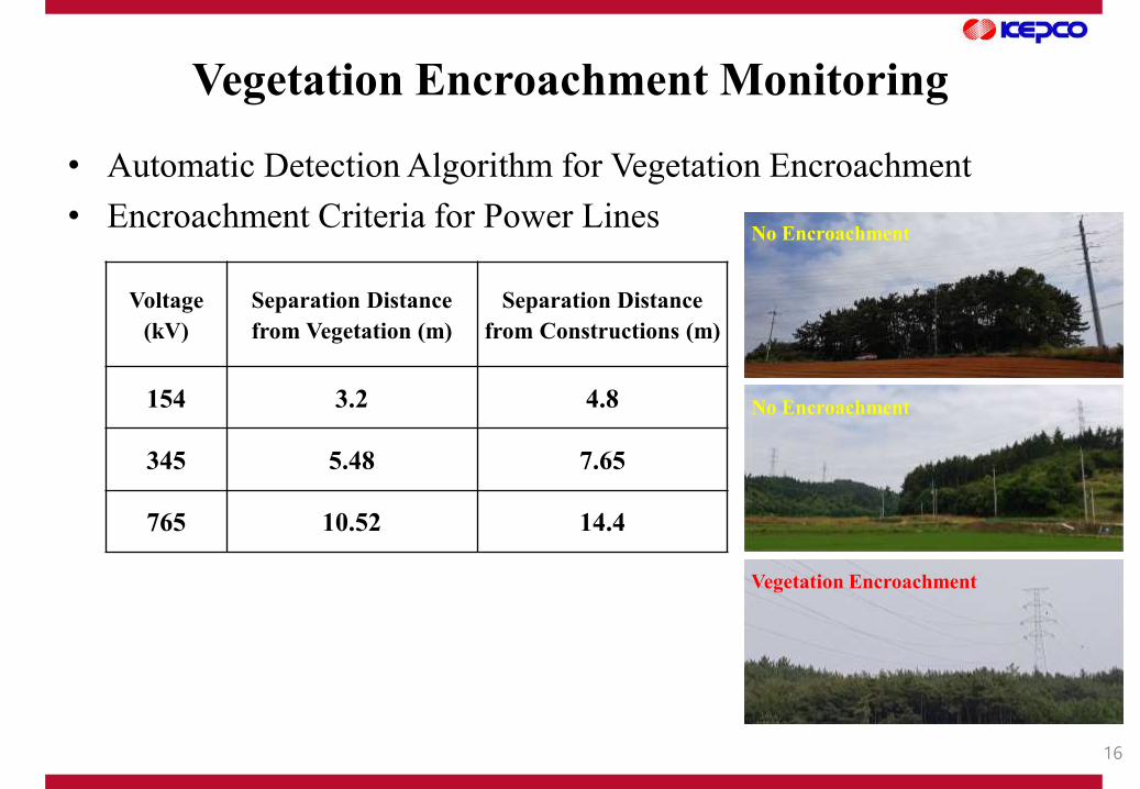
Vegetation Encroachment Monitoring
• Automatic Detection Algorithm for Vegetation Encroachment
• Encroachment Criteria for Power Lines
Voltage
(kV)
Separation Distance
from Vegetation (m)
Separation Distance
from Constructions (m)
154 3.2 4.8
345 5.48 7.65
765 10.52 14.4
No Encroachment
No Encroachment
Vegetation Encroachment

17
Field Test
• 154kV Seosan-Daesan T/L No. 56~57
• Airborne Laser Scanning using a LiDAR
was done from a Drone ☞ Point Cloud
Autopilot Flight Path
No. 57
No. 56

18
Vegetation Encroachment Monitoring
No Separation Distance [m]
P1 2.79
P2 3.01
P33.74 (No Swing)
2.83 (with 5.7° Swing)
P45.28 (No Swing)
3.19 (with 9.8° Swing)
• Automatic Detection Algorithm for Vegetation Encroachment
☞ Trees that encroach on electrical conductors shall be cut or trimmed.
Encroachment Criterion = 3.2 m for 154kV

19
Necessity of Automatic Camera Gimbal
• The Camera Gimbal is Remotely Controlled ☞ Control Problem in the Field
• Steel Tower Structure & Energized Power Conductors induced RF Interference
☞ Auto-tracking Camera Gimbal on the basis of Deep Learning
Thermal
OpticalZoom

20
Deep Learning for Auto-tracking
• The Real-time Tracking Performance is the Most Important Requirement.
☞ CNN YOLOv2 & Darknet Reference as its Backbone Feature Extractor
were chosen.
Detection Framework Train mAP FPS
Fast R-CNN 2007+2012 70.0 0.5
Faster R-CNN VGG-16 2007+2012 73.2 7
Faster R-CNN ResNet 2007+2012 76.4 5
YOLO 2007+2012 63.4 45
SSD300 2007+2012 74.3 46
SSD500 2007+2012 76.8 19
YOLOv2 416×416 2007+2012 76.8 67
Model Top-1 Top-5 Ops GPU CPU
AlexNet 57.0 80.3 2.27Bn 3.1 ms 0.29 s
Darknet Reference 61.1 83.0 0.96Bn 2.9 ms 0.14 s
VGG-16 70.5 90.0 30.94Bn 9.4 ms 4.36 s
Darknet 19 72.9 91.2 7.29Bn 6.2 ms 0.87 s
Resnet 50 75.8 92.9 9.74Bn 11.4 ms 1.13 s
Densenet 201 77.0 93.7 10.85Bn 32.6 ms 1.38 s

21
Deep Learning for Auto-tracking
• YOLOv2 Architecture
Input Layer
Conv.
16x416x416
Conv.
32x208x208
(3x3)(3x3)
Max Pool.
16x208x208
(2x2)
Stride 2
Max Pool.
32x104x104
(2x2)
Stride 2
AvgPool
Output Layer
SoftMax
3x416x416
Conv.
64x104x104
(3x3)
Max Pool.
64x52x52
(2x2)
Stride 2
Conv.
128x52x52
(3x3)
Max Pool.
128x26x26
(2x2)
Stride 2
Conv.
256x26x26
(3x3)
Max Pool.
256x13x13
(2x2)
Stride 2
Conv.
512x13x13
(3x3)
Max Pool.
512x13x13
(2x2)
Stride 1
Conv.
1024x13x13
(3x3)
Conv.
1024x13x13
(3x3)
54x13x13
Insulator String
16 32 64 128 256 512 1024

22
Image Database of Line Components
• To Increase Data Sets and
To Make the Algorithms
More Statistically Invariant,
- Expanded by image transformation
such as Gray Scaling, Flipping,
Mirroring, and Rotating
Line Component Original Images Training Images Test Images Total
Spacer (Damper) 5,672 40,812 4,564 45,376
Aerial Ball 4,128 7,479 777 8,256
Lightning Arrester 4,678 16,793 1,919 18,712
Porcelain Insulator 10,728 83,756 9,356 93,112
Polymer Insulator 393 2,815 329 3,144
SB Damper 7,024 44,152 5,016 49,168

23
Training Neural Networks
• More emphasis on Training of Porcelain Insulators, because a
tracking path for the gimbal is generated mainly along insulators.
<YOLOv2 Model Training Results>
Line Component Recall (%) Precision (%)
Spacer (Damper) 88.20 88.76
Aerial Ball 97.81 97.10
Lightning Arrester 74.19 72.33
Porcelain Insulator 92.64 94.37
Polymer Insulator 78.21 71.89
SB Damper 69.23 71.23
Average Detection
Time0.15 sec
FPS 7

24
Auto-tracking Camera Gimbal
• Automatic Image Diagnosis Algorithms using Deep Learning

25
BVLOS Flight
• BVLOS(Beyond Visual Line Of Sight) Flight
- Hydrogen Fuel Cell (DMI) + LTE Communication
- ’20.8 Special Approval for BVLOS Flight from Ministry of Land,
Infrastructure & Transport

BVLOS Flight
5 6
78 9
10
H
LTE
RF •
8
9
10
BVLOS Range
• Field Test (’20.7~’20.8)
- LTE / RF Duplex Communication
- Remote Control of Drone & Camera Gimbal

Thank You.
KEPCO Research Institute105 Munji-ro, Yuseong-Gu, Daejeon, 305-760, Koreawww.kepri.re.kr
• If you are interested in our technology, please contact us at