Ken Youssefi Mechanical Engineering Dept., SJSU 1 Creating a New Part File → New.
41
Ken Youssefi Mechanical Engineering Dept., SJSU 1 Creating a New Part File New →
-
Upload
gwendoline-fletcher -
Category
Documents
-
view
224 -
download
0
Transcript of Ken Youssefi Mechanical Engineering Dept., SJSU 1 Creating a New Part File → New.

Ken Youssefi Mechanical Engineering Dept., SJSU 1
Creating a New PartFile → New
Ken Youssefi Mechanical Engineering Dept., SJSU 2
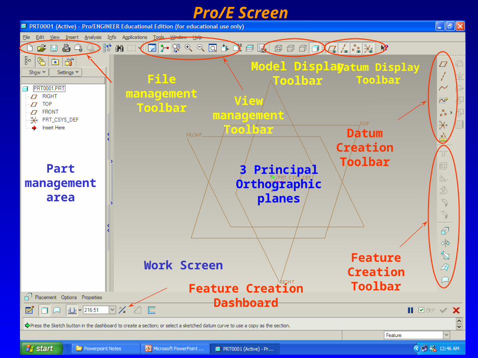
Pro/E Screen
File management Toolbar
Work Screen
3 Principal Orthographic
planes
Part management
area
Datum Display Toolbar
Model Display Toolbar
View management
Toolbar Datum Creation Toolbar
Feature Creation Toolbar
Feature Creation Dashboard

Ken Youssefi Mechanical Engineering Dept., SJSU 3
Default Toolbar

Ken Youssefi Mechanical Engineering Dept., SJSU 4
Model Display

Ken Youssefi Mechanical Engineering Dept., SJSU 5
Pro/E Mouse Functions

Ken Youssefi Mechanical Engineering Dept., SJSU 6
Default Datum Planes in Pro/E Three Standards Principal Orthographic Planes
Top
Right
Front

Ken Youssefi Mechanical Engineering Dept., SJSU 7
Creating SolidsSketched Features - (extrusions, revolves, sweeps, blends, ..) These features require a two-dimensional drawing (cross section) which is then manipulated into the third dimension. Although they usually use existing geometry for references, they do not specifically require this. These features will involve the use of an important tool called Sketcher. Select a datum plane to draw. Create a 2D sketch. Create a feature from the sketch
by extruding, revolving, sweeping, ….
Revolve
Sweep
Blend
Extrude
Ken Youssefi Mechanical Engineering Dept., SJSU 8
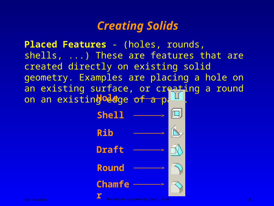
Creating Solids
Placed Features - (holes, rounds, shells, ...) These are features that are created directly on existing solid geometry. Examples are placing a hole on an existing surface, or creating a round on an existing edge of a part.
Shell
Rib
Draft
Hole
Round
Chamfer
Ken Youssefi Mechanical Engineering Dept., SJSU 9
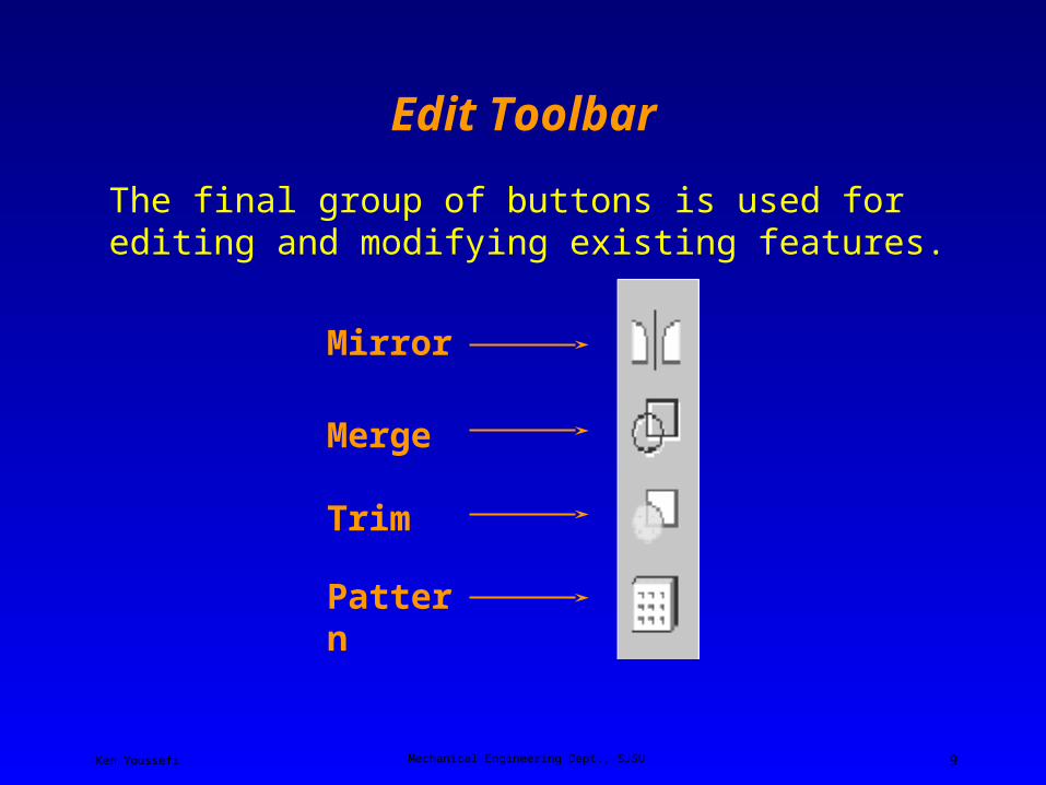
Edit Toolbar
The final group of buttons is used for editing and modifying existing features.
Merge
Trim
Pattern
Mirror

Ken Youssefi Mechanical Engineering Dept., SJSU 10
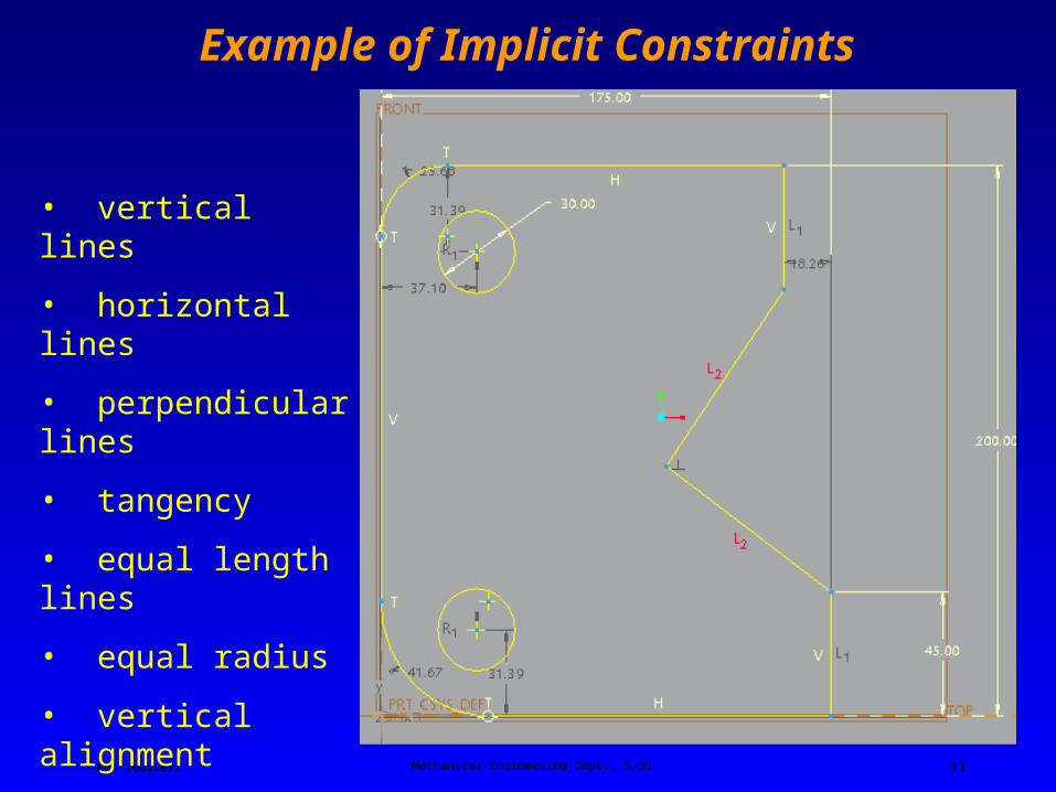
Implicit Constraints in Sketcher
Ken Youssefi Mechanical Engineering Dept., SJSU 11
• vertical lines
• horizontal lines
• perpendicular lines
• tangency
• equal length lines
• equal radius
• vertical alignment
Example of Implicit Constraints

Ken Youssefi Mechanical Engineering Dept., SJSU 12
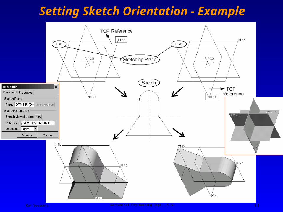
Setting Sketch Orientation
Sketch plane - the plane on which you will draw and your view is always perpendicular to the sketch plane.
The Orientation option list in the dialog window (Top, Bottom, Left, Right) refers to directions relative to the computer screen, as in “TOP edge of the screen” or “BOTTOM edge of the screen” and so on. This orientation must be combined with a chosen reference plane (which must be perpendicular to the sketch plane) so that the desired direction of view onto the sketching plane is obtained.
Ken Youssefi Mechanical Engineering Dept., SJSU 13
Setting Sketch Orientation - Example

Ken Youssefi Mechanical Engineering Dept., SJSU 14
Sketcher

Ken Youssefi Mechanical Engineering Dept., SJSU 15
The Sketcher Toolbar
Ken Youssefi Mechanical Engineering Dept., SJSU 16
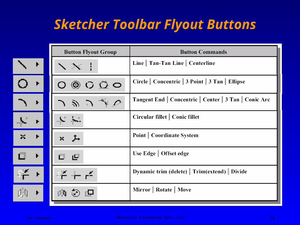
Sketcher Toolbar Flyout Buttons
Ken Youssefi Mechanical Engineering Dept., SJSU 17
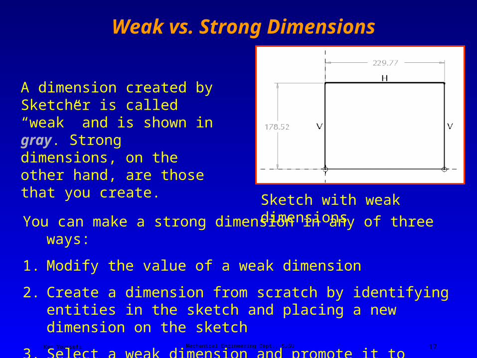
Weak vs. Strong Dimensions
Sketch with weak dimensions
A dimension created by Sketcher is called “weak” and is shown in gray. Strong dimensions, on the other hand, are those that you create.
You can make a strong dimension in any of three ways:
1. Modify the value of a weak dimension
2. Create a dimension from scratch by identifying entities in the sketch and placing a new dimension on the sketch
3. Select a weak dimension and promote it to strong using the RMB pop-up menu

Ken Youssefi Mechanical Engineering Dept., SJSU 18
Over and Under Constrained Sketch
If there is not enough information to define the drawing (it is underconstrained), Sketcher will create the necessary and sufficient missing dimensions.These are the weak dimensions.If Sketcher finds the drawing is overconstrained (too many dimensions or constraints) it will first try to solve the sketch by deleting one or more of the weak dimensions (the ones it made itself earlier).However, if Sketcher still finds the drawing overconstrained, it will tell you what the redundant information is (which may be dimensions or constraints),

Ken Youssefi Mechanical Engineering Dept., SJSU 19
Extrude Command in Pro/E
Extrude
The Extrude DashboardExtrude Icon
Select Placement to define the sketch plane
SolidSurface
Depth options
Blind depth
Thicken SketchRemove material (cut)
Flip direction
Ken Youssefi Mechanical Engineering Dept., SJSU 20
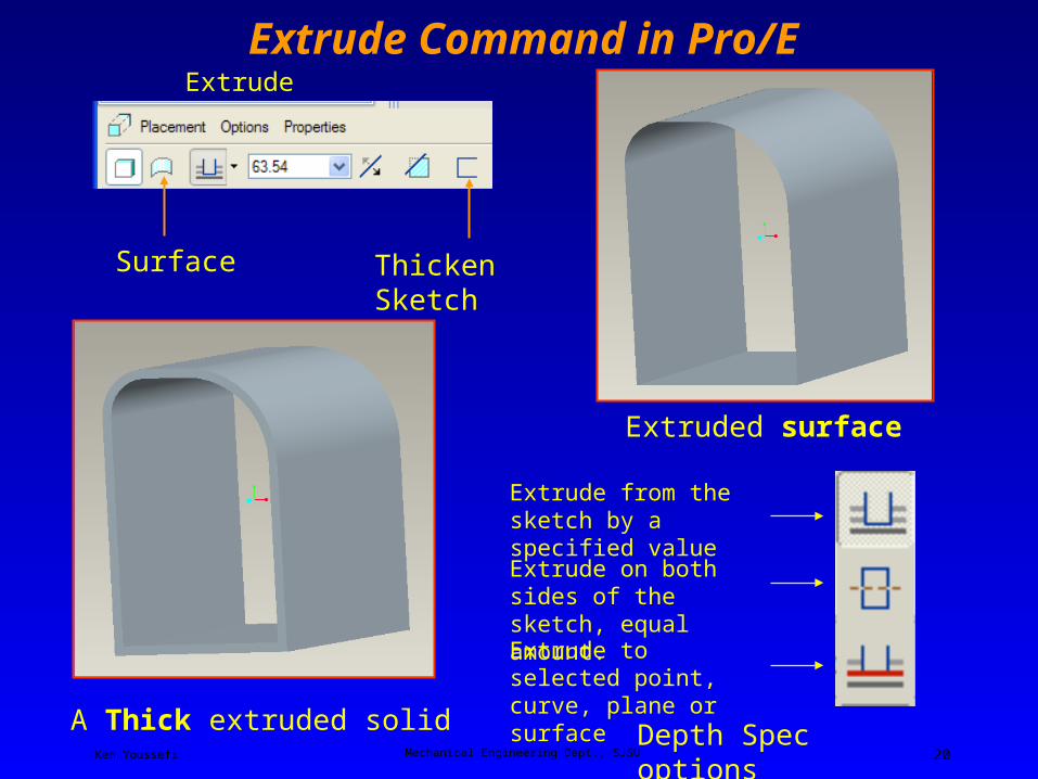
Extrude Command in Pro/E
Extruded surface
Extrude Dashboard
Surface
Depth Spec options
Extrude to selected point, curve, plane or surface
Extrude on both sides of the sketch, equal amount.
Extrude from the sketch by a specified value
Thicken Sketch
A Thick extruded solid

Ken Youssefi Mechanical Engineering Dept., SJSU 21
Creating an Extruded Cut
1. Select a plane to sketch on, cannot sketch on a curved surface.
2. Sketch the curve
3. Select Remove Material button
Remove Material

Ken Youssefi Mechanical Engineering Dept., SJSU 22
Creating an Extruded Cut
Common dashboard controls
Material removal arrow pointing to the right.
Material Removal Side
Material removal arrow pointing to the left.
Ken Youssefi Mechanical Engineering Dept., SJSU 23
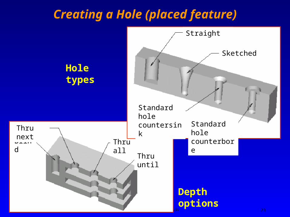
Blind
Thru next
Thru all
Thru until
Depth options
Creating a Hole (placed feature)
Hole types
Straight
Sketched
Standard hole counterbore
Standard hole countersink

Ken Youssefi Mechanical Engineering Dept., SJSU 24
Creating a Hole (placed feature)
Hole placement: linear or radial
The Straight hole dashboard (default)
Standard threaded hole option

Ken Youssefi Mechanical Engineering Dept., SJSU 25
Chamfer and Fillet (Round)
RoundChamfer
Chamfer Dashboard
Round Dashboard
Ken Youssefi Mechanical Engineering Dept., SJSU 26
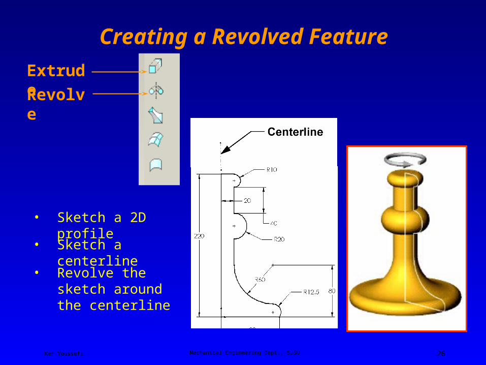
Creating a Revolved Feature
• Sketch a 2D profile
• Revolve the sketch around the centerline
Revolve
Extrude
• Sketch a centerline
Ken Youssefi Mechanical Engineering Dept., SJSU 27
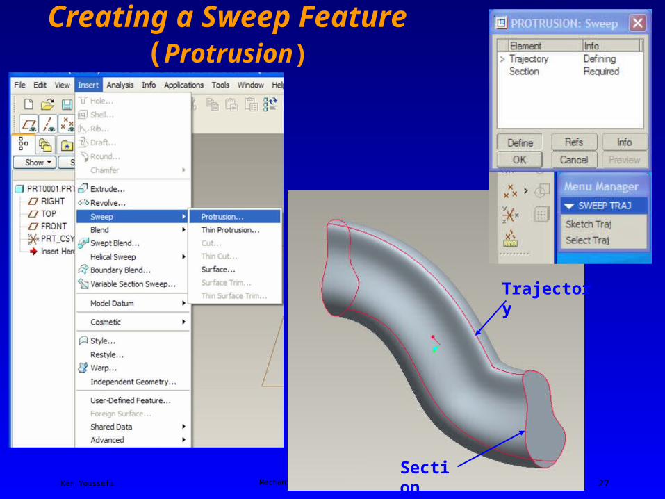
Creating a Sweep Feature (Protrusion)
Trajectory
Section

Ken Youssefi Mechanical Engineering Dept., SJSU 28
Creating a Sweep Feature (Cut)
Create an entity from an edge
Pick the top surface of the table top to sketch, insert the two edges of the table into the sketch plane for reference, erase after finished.
Sketch the sweep trajectory (guide sweep)
Trajectory

Ken Youssefi Mechanical Engineering Dept., SJSU 29
Creating a Sweep Feature (Cut)
select Insert → Sweep → Cut, and choose the Select Traj. option

Ken Youssefi Mechanical Engineering Dept., SJSU 30
Creating a Sweep Feature (Cut)Sketch the cut profile on the back surface f the table top
Back surface
Ken Youssefi Mechanical Engineering Dept., SJSU 31
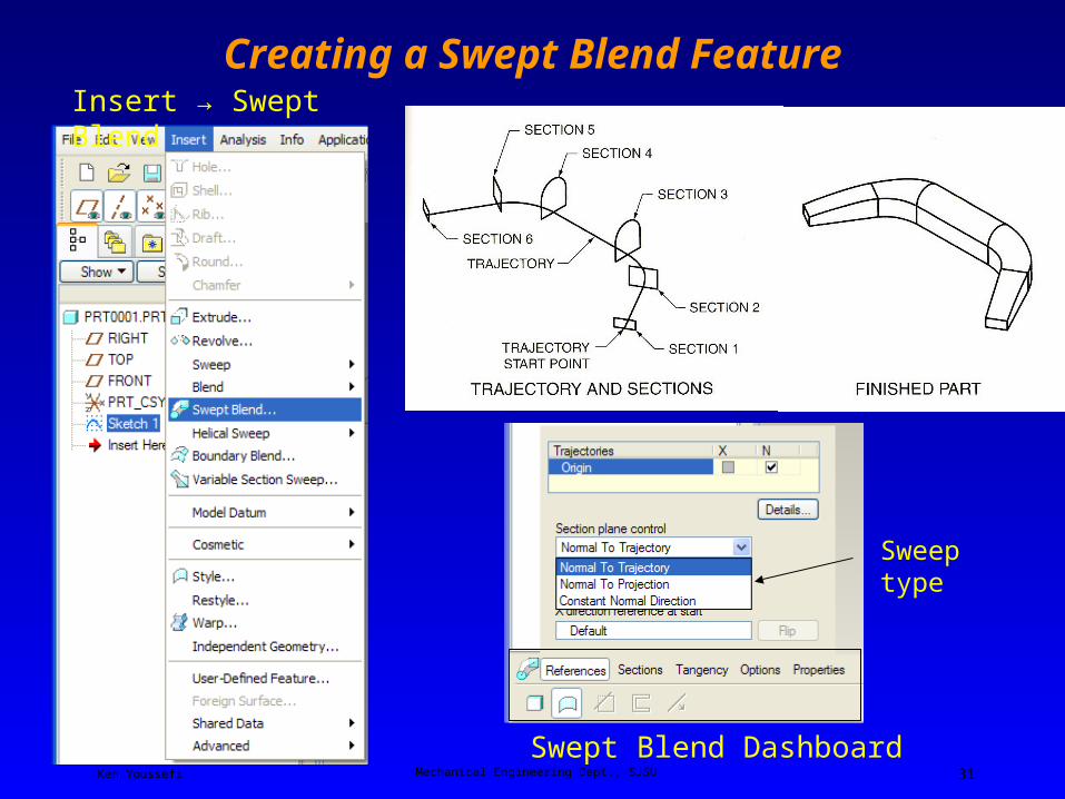
Creating a Swept Blend Feature
Swept Blend Dashboard
Sweep type
Insert → Swept Blend
Ken Youssefi Mechanical Engineering Dept., SJSU 32
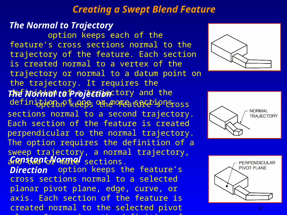
Creating a Swept Blend Feature
option keeps each of the feature’s cross sections normal to the trajectory of the feature. Each section is created normal to a vertex of the trajectory or normal to a datum point on the trajectory. It requires the definition of a trajectory and the definition of one or more sections
option keeps the feature’s cross sections normal to a selected planar pivot plane, edge, curve, or axis. Each section of the feature is created normal to the selected pivot plane. It requires the definition of a trajectory a normal plane and the definition of one or more sections.
Constant Normal Direction
option keeps the feature’s cross sections normal to a second trajectory. Each section of the feature is created perpendicular to the normal trajectory. The option requires the definition of a sweep trajectory, a normal trajectory, and two or more sections.
The Normal to Projection
The Normal to Trajectory

Ken Youssefi Mechanical Engineering Dept., SJSU 33
Creating a Swept Blend Feature - Examples
The Normal to Projection
The Normal to Trajectory
Ken Youssefi Mechanical Engineering Dept., SJSU 34
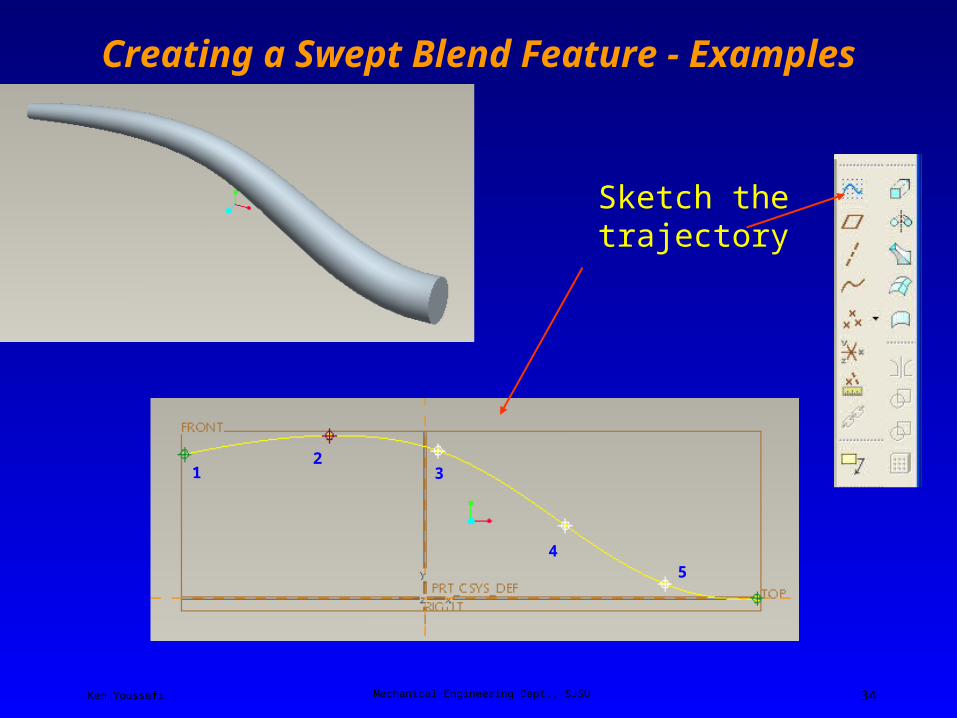
Creating a Swept Blend Feature - Examples
Sketch the trajectory
12
3
45
Ken Youssefi Mechanical Engineering Dept., SJSU 35
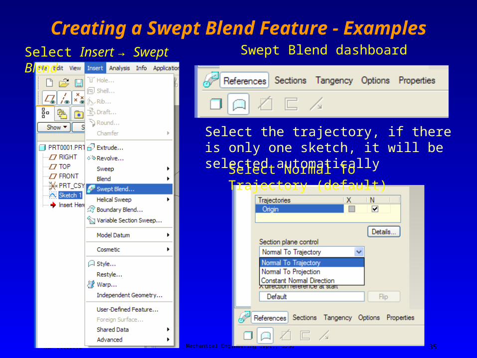
Creating a Swept Blend Feature - ExamplesSelect Insert → Swept Blend Swept Blend dashboard
Select Normal To Trajectory (default)
Select the trajectory, if there is only one sketch, it will be selected automatically

Ken Youssefi Mechanical Engineering Dept., SJSU 36
Swept Blend Feature - Example
Select a point and sketch the cross section
12
34
5

Ken Youssefi Mechanical Engineering Dept., SJSU 37
Select Insert when finished with the sketch
Follow the same steps to draw the other sections
Ken Youssefi Mechanical Engineering Dept., SJSU 38
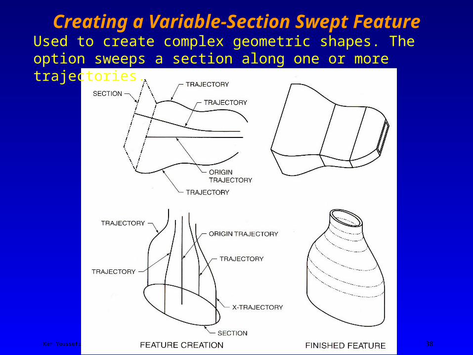
Creating a Variable-Section Swept FeatureUsed to create complex geometric shapes. The option sweeps a section along one or more trajectories.

Ken Youssefi Mechanical Engineering Dept., SJSU 39
Creating a Datum Plane Tangent to a Curve at a Point
Select the curved plane and the Tangent option
A
Select Datum Plane

Ken Youssefi Mechanical Engineering Dept., SJSU 40
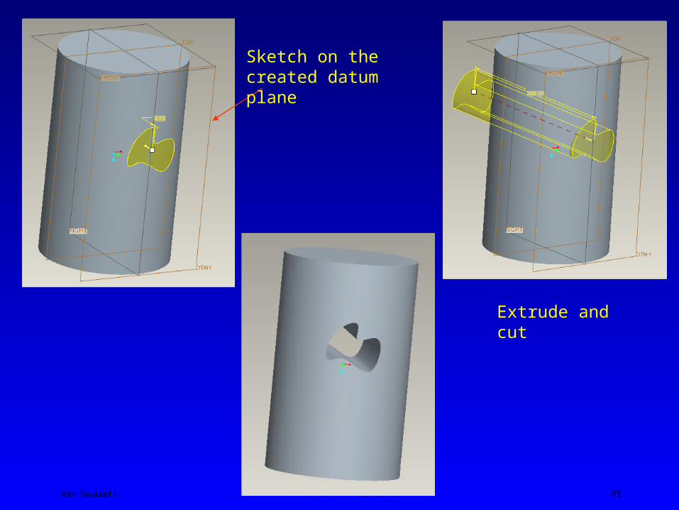
Creating a Datum Plane Tangent to a Curve at a Point
Select the end point of the line, the datum plane is tangent to the cylinder at point A.
Ken Youssefi Mechanical Engineering Dept., SJSU 41
Sketch on the created datum plane
Extrude and cut