KEI’i?HLEY INSTRUME.&TS,
33
KEI’i?HLEY INSTRUME.&TS,
Transcript of KEI’i?HLEY INSTRUME.&TS,

KEI’i?HLEY INSTRUME.&TS,

warranty We warrant each of our products to be free from defects in material atid workmanship. ,Our obligation under this warranty iS’to repair or replace any instrument or part thereof which, within a year after shipment, proves defective upon examination. We will pay local domestic surface freight costs.
To exercise this warranty, write or call your local Keithley ~repre- . sentative, or contact Keithley headquarters in Cleveland, Ohto. You will be given. prompt assistance and shipping instructions.
repairs and; calibrat,ion Keithley lnstrbments~ maintains a compl&e repair~,and.calibration service as well as a standards laboratory in Cleveland, Ohio. A, service facility is also located in Los Angeles for c&r west coast customers.
A Keithley service facility at our Munich, Germany office is available for our customers throughout Europe. Service in the United Kingdom can be handled at our office i,n Reading. Addition- ally, Keithley representatives in most countries maintain service and calibration facilities..
To insure prompt repair or recalibration service, ,please contact your local field representative or Keithley headquarters directly before returning the instrument. Estimates for repairs, normal recalibrations and calibrations traceable to the National Bureau of Standards are available upon request.
KEI’I’HHLEY INSTRUMENTS 20776 AURORA ROAD * CLEVELAND, OHIO 44130
TELEPHONES (216.) 248-0400 . TELEX OS-6468
E”roC.*n”dw*: 14 A”*. “ill.rd~n . CH-the Pull”. 6”iS.. . ,021, 261168 Unlt~dKln#dom~ ~~oulton RowI * Reading e Berkahfre a (07341 861287 W.,, 6.man”: Hei6lho‘.lr.*.. 3a . D-6000 Munch.” 70 . ,081,l 74632, F,*nc*: 44 Rue *n*101. r=r.nc. . 61120 PaIa,s..u . (01, 626-0046161

INSTRUCTION MANUAL
MODEL 4lOA
Picoammeter
@COPYRIGHT 1976, KEITHLEY INSTRUMENTS, INC.
PRINTED APRIL 1976, CLEVELAND, OHIO, U.S.A.

CONTENTS MODEL 410A
CONTENTS
SeCtiO” Page
SPEClFIC*TIONS------------------------------------------------------------- iv
1, GENERAL DESCRIPTION---------------------------------------------------- 1
2, OPERATION-------------------------------------------------------------- 4
3, CIRCUIT DESCRIPTION---------------------------------------------------- 6
4, SER"ICING-------------------------------------------------------------- ,
5. CAL~BRATION------------------------------------------------------------ 9
,j. *CCESSOBIES------------------------------------------------------------ 15
7. REPLACEABLE PARTS------------------------------------------------------ 18
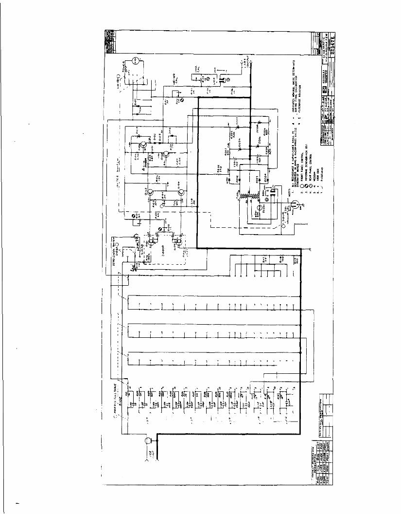
SCHEMATIC------------------------------------------------------------------ 24
0275
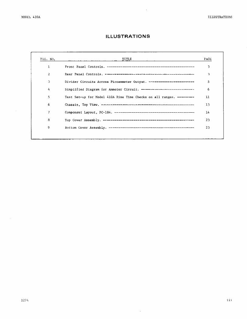
ILLUSTRATIONS
FIG. NO. TITLE PAGE
1 Front pane1 Controls, ___--____-__________-------------------------- 3
2 Rear Panel Conrrols, ____-____-____-_________________________------- 3
3 Divider circuits *cross Picoamerer outpur. ------------------------ 5
4 Simplified Diagram for Ameter Circuit. ---------------------------- 6
5 Test Set-up for Model 410A Rise Time Checks an all ranges. --------- 11
6 Chassis, Top View. ________________________________________--------- 13
7 componenr Layour, p+1p,4, ____--___--_____________________________-- 14
8 Top cover *ssem~ly. __-_______--____________________________-------- 23
9 Bottom cover Assembly. -----_--------_------------------------------ 23
SPECIFICATIONS MODEL 410A
SPECIFICATIONS
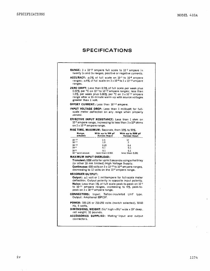
RANGE: 3 x 10’13 ampere full scale to 10.3 ampere in twenty Ix and 3x ranges. positive or negative currents.
ACCURACY: 12% of full scale on 10’” to XV ampere ranges: *4%off”li scaleon 3 x 10+to3 x 10’~~ampere ranges.
ZERO DRIFT: Less than 0.5% of full scale per week plus 0.02% per “C on ice to l0.y ampere ranges; less than 1.5% per week plus 0.06% per “C on 3 x 1Q.13 ampere range after a l&minute warm-up with source voltage* greater than 1 “OIL
OFFSET CURRENT: Less than lo-” ampere.
INPUT VOLTAGE DROP: Less than 1 millivolt for full. scale meter deflection on any range when properly zeroed.
EFFECTIVE fNPUT RESISTANCE: Less than 1 ohm on lo’” ampere range, increasing to less than 3 x 10⁹ ohms on 3 x lo“3 ampere range.
RISETIME, MAXIMUM: Seconds, from 10% to 90%. Range, With Yp to 100 pF Wl,h YP to 5000 pf ampere AC.0.I lnpYt A6rOSL l”PY,
IO-” 2.5 12 IL? 1 I 1.0 2 IO-‘0 0.25 cl.4 IO- 3 0.1 0.1 1Q.a 0.1 0.1 10-T and above less tnan 0.001 kS5 than 0.001
MAXlMUM INPUTOVERLOAD: Transiant:1QQQvoltsforupto3secondsusinga Keithley (or other 10 mA limited) High Voltage Supply. Continuous:6QQvoltson3 Y 10’llto Wampere ranges. decreasing to 12 volts on the 1Q’2 ampere range.
RECORDEROUTPUT: Output: *I volt or 1 milliampere for fullxale meter deflection. Output polarity i* opposite input polarity. Noise: Less than 1% of full scale peak.to-peak on 10’” to 10’” ampere ranges. increasing to 5To peak-ta- peak on 3 x llT~‘ampere range.
CONNECTORS: Input: Teflon.insulatod UHF type. Output: Amphenol 8QPCZF.
POWER: 105.125 or 210.250 volts (switch selected). 50.60 Hz, 5 watts.
DIMENSIONS, WEIGHT: 5%” high x 8%” wide x 10” deep; net weight. 10 pounds.
ACCESSORIES SUPPLIED: Mating-input and output Con”ector*.
iv 1274

CN410A-4 Sheet I of I 0776
KEITHLEY INSTRUMENTS. I No C
INSTRUCTION MANUAL CHANGE NOTICE
MODEL 4lOA PICOAMMETER
INTRODUCTION: Since Keithley Instruments is continually improving pro- duct performance and reliability, it is often necessary to make changes to Instruction Manuals to reflect these improvements. Also, errors in Instruction Manuals occasionally occur that require changes. Sometimes, due to printing lead time and shipping requirements, we can’t get these changes immediately into printed Manuals. The following new change in- formation is supplied as a supplement to this Manual in order to provide the user with the latest improvements and corrections in the shortest possible time. Many users will transfer this change information directly to a Manual to minimize user error. All changes or additions are indi- cated in italics.
CHANGES :
PAGE I9
Q103 PNP, Case R-110 F-I Sl7638 1”G-33 7 Q104 PNP, Case R-110 F-I 527638 T&33 7
+‘:;Replace QIOI, QIOZ or RI16 by ordering Plug-in board 23733.
SECTION 1. GENERAL DESCRIPTION
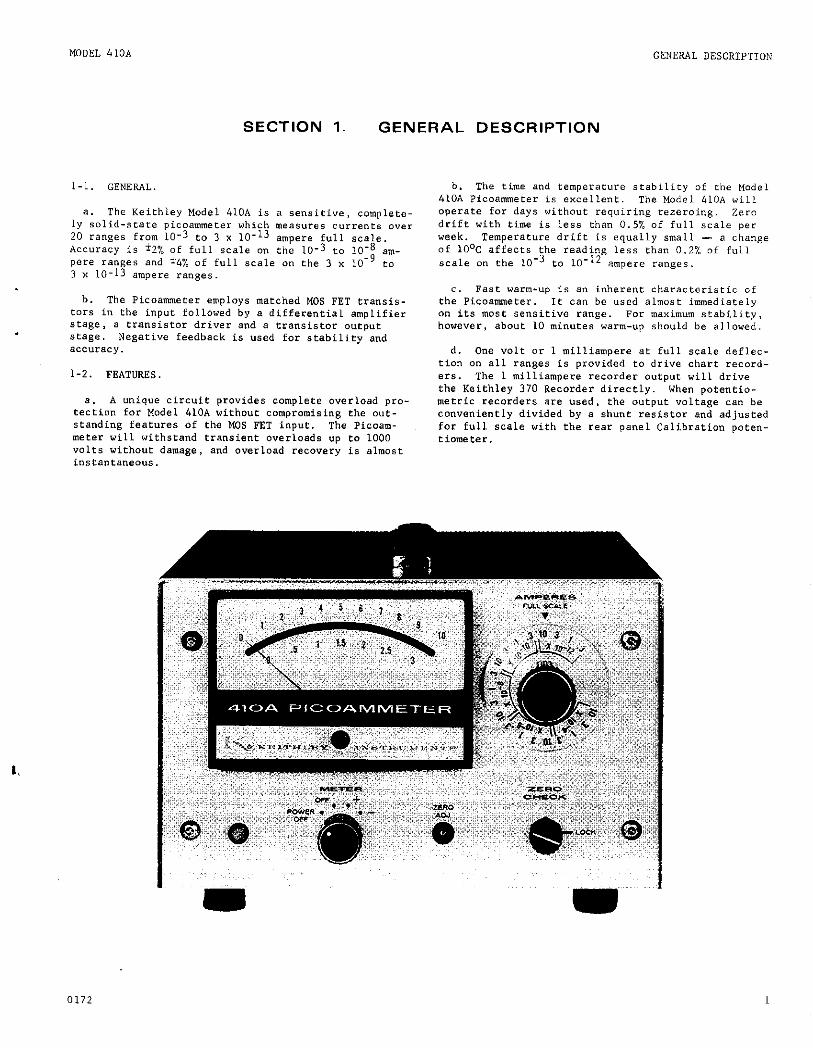
l-1. GENERAL.
a. The Keithley Model 410A is a sensitive, complete- ly solid-state picoammeter which measures currents over 20 ranges from 10-3 to 3 x 10-13 ampere full scale. accuracy is b% of full scale on the lo-3 to 10-B am- pere ranges and 14% of full scale on ctle 3 x 10⁹ co 3 x 10-13 ampere ranges.
b. The Pic"ammeeer employs matched MOs FET transis- tars in the input followed by a differenrial amplifier stage, a transistor driver and a transistor O"epUC stage. Negative feedback is used for stability and aCC"rXy.
1-2. FEATURES.
a. A unique circuit provides complete overload pro- tection for Model 410.~ without compromising the out- standing features of the MOS FET input. The Picoam- meter will withstand transient overloads up CO 1000 volts wirhout damage, and overload recovery is almost instantaneous.
b. The time and temperature stability of the Model 410A Picoamneter is excellent. The Model 410.4 will operate for days without requiring rezeroing. Zera drift with time is less than 0.5% of full scale per week. Temperature drift is equally small - a change of 10°C affects the reading less than 0.2% of full scale on ehe 10‘3 to 10-12 ampere ranges.
c. Fast warm-up is an inherent characterisric of the Picoammeter. It can be used almost immediately on its most SensiCive range. For maximum seability, however, about 10 minutes warm-up should be allowed.
d. One volt or 1 milliampere at full scale deflec- fFon on all ranges is provided to drive chart record- ers. The 1 milliampere recorder output will drive the Keithley 370 Recorder directly. When potentio- metric recorders are used, the output voltage ca" be conveniently divided by a shunt resistor and adjusted for full scale with the rear panel Calibration paten- tiometer.
0172 1

GENERAL DESCRIPTION MODEL 410A
Control
AMPERES Switch
METER Switch.
ZERO ADJ. Control
Pilot Light
ZERO CHECK Sutton
TABLE 2. Model 410A Front Panel Conrrols (Figure 1).
Funceional Description Par.
selects full-scale Current range instrument is to measure. 2-2
Turns inserument on; selects meter polarity. Z-2,2-4
ZemeS meter on any range. 2-2
Glows to indicate instrument is on. ___
Checks zero on any range. _--
CO”tlWl Functional Description Par. I
INPlsI Receptacle connects input to source. receptacle is a Teflon-insulated UHF 2-1,2-z co""ectar.
Olsi"PuT Receptacle connects output to monitoring device. 2-4
1 MA - 1 ” Switch Selects output of instrument: 1 milliampere or 1 volt. 2-4
1 MA CAL Control Adjusts output from 0.95 eo 1.05 mA. 2-4
117-234 " Switch sets instrument for 117 or 234 Volt ac power line. z-2,2-5
Fuse 3Acz Slow-Blow. 117 volt - ,125 A; 234 volt - ,062 A. 2-5
2 0172

MODEL 410A GENERAL OESCRIPTTION
FIGURE 2. sear Panel Controls.
0172 3

OPERATION
SECTION 2. OPERATION
MODEL 41OA
2-l. INPUT CONNECTIONS. “se the following precautions e. Attach the current source to the INPUT Kecepta- when using the Picoammeter on the more sensitive ranges. cle and turn the METER Switch to rhe polarity of the
input signal, + or -. Increase sensieivity with the AMPERES Switch until the greatest on scale deflection is achieved.
a. The INPUT Receptacle of the Model 410~ is a Tef- 1. When the AMPERES Switch is see to 10, I, 0.1, Ion-insulated UHF co”“ector. The ce”Ler rermina1 is etc. positions, use the upper meter scale. Full the high impedance terminal, and the outer shield is scale current range is equal LO the AMPERES Switch ca?,e ground. setting.
b. Carefully shield rhe input connection and the 2. When the AMPERES Switch is set to 3, 0.3, 0.03, current source being measured, since power line frequen- etc. positions, use the lower meter scale. Full ties are well within the pass band of the Picoammeter scale current range is equal to the AMPERES Swirch on all ranges. unless the shielding is thorough, pick- setting. up may cause definite meter disturbances.
c. Use high resiseance, low-loss materials - such as polyethylene, polystyrene or Teflon - for insula- tion. The insulation resistance af test leads and fix- turee should be several orders of magnitude higher than the So”rCe resistance. Excessive leakage will reduce accuracy. Any coaxial cable used should be a low-noise type which employs a graphite coating between the die- lectric and the surrounding shield braid.
d. Any change in the capacitance of the measuring circuit to ground will cause disturbances in the read- ing, especially an the more sensitive ranges. Make the measuring setup as rigid as possible, and tie down con- necting cables to prevent their movement. If a contin- uous vibration is present, it may appear at the atput as B sinusoidal signal and other precautions may be necessary to isolate the instrument and the connecting cable from the vibration.
2-2. OPERATING PROCEDURES.
a. Check the fuse and the 117-234 Line Switch for the proper line voltage.
~,
b. Connect the power card to the power saurce.
c. Set the AMPERES Switch to 10 x 1O-4 ampere and the METER Switch f~ (c). Within seconds the meter needle should read zero, Zero the meter with the ZERO ALU. Control. After a few moments increase the current sensitivity by advancing the AMPERES Switch in decade steps LO the .3 x 10-12 ampere range. continue zero- ing with the ZERO A”J. Control. The instrument is now ready to use.
d. If long term measurements are ea be made, allow the instrument to “arm up far at least 10 minutes.
2-3. MEASUREMENT CONSIDERATIONS.
a. The Picoammeter employs the fast method of cur- ren? measurement - the measuring resistor is between the amplifier input and output in the feedback loop. This method largely neutralizes the effecr of input capacity and greatly increases the response speed. Also, the input voltage drop is reduced to a maximum of One millivolt On any range.
b. Rise time varies with the current range and the input capacity (see specifications, Table 1). The rise time, though, is not affected with up ea 500 picofarads across the input; however, it is better to place the Picoammecer nearer the current scnrce than to the data reqding instrument, Transmitting the input signal through long cables - with greater than 500 picofarads of capacitance - “ill increase response time and meter noise, especially on ranges below lo-10 ampere.
c. The internal resistance of the unknown source should not be less than the reciprocal af the current range being used, otherwise the zero stability “ill be affected. The instrument will still be operable, how- ever, but the sensitivity will be approximately
RF/R, Equation 1.
where Rf is the feedback resistance in ohms; and R, is the source resistance in ohms.
For example, if the eource to be measured has a resis- tance of 105 ohms and the current is 10-6 then tbe feed- back resistor “ill be lo6 ohms. gain of the Picoammeter is 106110
This mean;h~~a:h~h~e,, = lo.
stability of .X/week “ill be .5X x 10 = Z%lweek, nnd the offset due to temperature “ill be .o2%xx1o x .2%/0c. This is the reason that it is advantageous +a have the source resistance at least equal Co the feedback resis- ear.
4 0172

MODEL 4lOA OPERATION
TABLE 4. Allowable Overloads on Ranges Abo”e LO-6 Ampere.
&lx. continuous Man. continuous Range Voltage Overload current Overload
10-5 A d A
300 " ImA 120 "
10-3 4mA
A 30 v 10 * 10-2 A 12 v 40 In4
d. Overload Protecfion. A unique circuit provides complete overload protection for rhe Model 410A without compromisi”~ the features of the MOS FET input. over- load recovery is almost i”stn”taneous on the 10-10 amp- ere range and above. Howe”er, an the more sensitive ranges, especially o” the 3 x lo-l3 ampere range, the instrument may develop considerable offset which may take anywhere from .9 few minutes co a few hours to dis- appear.
1. on the 104 ampere range and below the ~icoam- meter can withstand overloads of up to 1000 volts for 3 seconds and continuous overloads of up to 600 volts wirhaue damage.
2. nor ranges above 10-6 ampere, the maximum con- tinuous overload is restricted due to the power dis- sipation of the feedback resistors (See Table 4).
3. For maximum protection, use a Keithley Model 24OA Voltage Supply or some other 10 milliampere cur- rent limited supply in combination with the ~icoam- meter.
2-4. RECORDER OUTPUTS.
a. For recording with the Model 410A, use the Keith- icy wade1 370 Recorder for ease, eco”omy,‘“ersatil- ity and performance. The Model 370 is a pen recorder with 10 chart speeds and 1% linearity. The Model 370’s input cable has a connector which mates directly with the OUTPUT Connector on the Picoammeter; this avoids interface problems often encountered between a meas- uring instrument and a recorder. The Pifoammeeer out- put, when set to the 1 MA Posifio”, will drive the 370; no preamplifier is needed. No special wiring is required.
b. Other recorders, oscilloscopes and similar in- sfruments can be used wieh the Model 410A. The Pico- ammeter has two outputs, *I volt and *I milliampere, to amplify signals for recorders, oscilloscopes and similar instruments. These can be used on all ranges.
c. l-Volt OUtpUt, connect oscilloscopes and pen recorder amplifiers to the OUTPUT Receptacle. pi” no. 1 is the high terminal and pin no. 2 is ground. Set LilC ! \L\ I ‘*’ Svitcll t” 1 I’. The Picoammeter output is now ii voLt for full scale meter deflection o” any rnnge. Internal resistance ie approximate?y 1 kilohm. Noise is less than 1% of full scale peak-to-peak on the 10-l to 10-11 ampere r*e~e~,,%iy;rm&;p ‘b~mT,,,R peak-to-peak on the 3 v 10‘ Switch does nof reverse the oueput polarity. output polarity is always opposite input polarity.
PICURE 3. Divider Circuits Across Picoameter Output for Driving 50 and IOO-millivolt Recorders. use 5% resistors in the dividers. The value of resistor R is one ohm for every 1 m!’ of output.
d. l-Milliampere output. Connect l-milliampere instruments to the 0”TP”T Receoeacle. Pin no. 1 is the high terminal. Set the 1 i.tA 1” Switch to 1 MA. *he oueput is approximately 1 milliampere for full- scale meter deflection on any range. For exact out- put, apply a know” full scale signal LO the Picoammeter and adjust the 1 MA CAL Control until the recorder reads full scale. Check the Recorder and meter zero and re- peat adjustment if necessary. The METER Switch does not revere.= the output polarity which is always oppa- site input polarity.
e. For servo rebalance recorders, use a divider across the Picoammeter Output Receptacle. See Figure 3. Set the OUTPUT Switch to 1 MA. “se the 1 MA CAL Control to trim the output for full-scale recorder de- flection. Operation is the same as for current out- puts.
2-5. 234-VOLT OPERATION. The instrument is shipped for use with a 117~volt power source unless otherwise ordered. To convert the Picoammeeer for 234~volt SOUIICBS, use a screwdriver to change the slide switch on the back panel to the 234.volt position. Change the fuse from 0.125 ampere LO ,062 ampere. NO ocher adjustment is necessary. To switch from 234 to 117- volt operation, reverse the procedures.
0172 5
CIRCUIT DESCRIPTION
SECTION 3. CIRCUIT DESCRIPTION
MODEL 41”A
3-l. GENERAL. The Keithley Model 410A is a linear dc amplifier with a full scale sensitivity of 0.3, 1 or 3 ““its. By using the front panel controls, shunt resis- tors are selected to make measurements over a toeal of 20 current ranges.
3-2. AMMETER OPERATION.
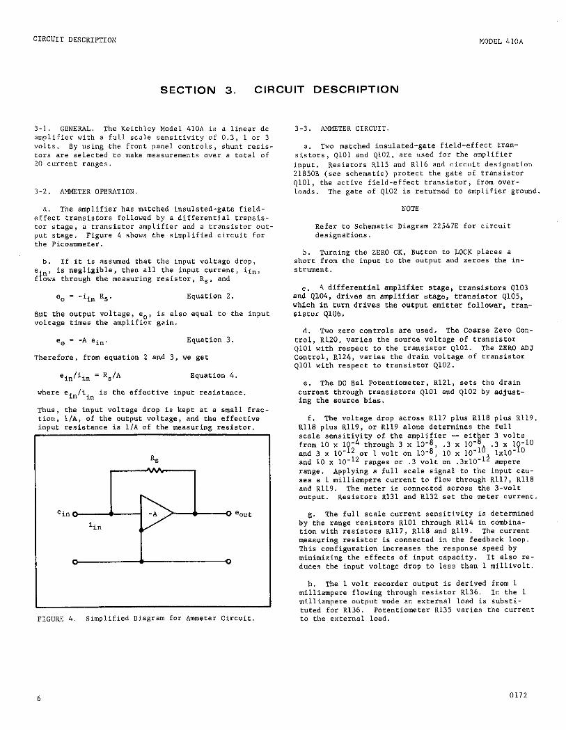
a. The amplifier has matched insulated-gate field- effect transiet”r8 followed by a differential transis- tor stage, a transistor amplifier and a transistor out- put stage. Figure 4 shows the simplified circuit for the Picoamnefer.
b. 1f it is assumed that the input voltage drop,
‘,p, is negligible, then all the input current, ii”,
ows through the measuring resistor, R,, and
=o = -iin Rs. Equation 2.
But the output voltage, e”, is also equal to the input voltage times the amplifier gain.
e. = -A ein. Equation 3.
Therefore, from equation 2 and 3, we get
ein/iin = Rs/A Equation 4.
where ein/iin is the effective input resistance.
Thus, the input voltage drop is kept at a small frac- tion, l/A, of the output voltage, and the effective input resistance is l/A of the measuring resistor.
=in o--J@0 %t
0 I 0
FIGURS 4. simplified Diagram for Ammeter Circuit
3-3. AMMETER CIRCUIT
a. Two matched insulared-gare field-effect tran- sistors, ~101 and Q102, are used for the amplifier input. Resistors ~115 and R116 and circuit designation 21850B (see schematic) protect the gate of tran~ietor QlOl, the active field-effect transistor, from “ver- loads. The gate of Q102 is returned to amplifier ground.
NOTE
Refer to Schematic Diagram 22547E for circuit designations.
b. Turning the ZERO CK. Button to LOCK places a short from the input to the output and zeroes the in- strument.
4 differential amplifier stage, transistors Q103 andC’Q104, drives an amplifier stage, transisror 9105, which in turn drives the output emitter follower, tran- SlSE”r QIOb.
d. Two zero controls are used. The Coarse Zero Con- trol, R120, varies the source voltage of transistor QlOl with respect to the franeistor Q102. The ZERO ADJ ConeroL, R124, varies the drain voltage of transistor QlOl with respect to rransistor 4102.
e. The DC Bal Potentiometer, R121, sets the drain current through transistors QlOl and Q102 by adjust- ing the source bias.
f. The volrage drop across ~117 plus Rllg plus R119, R118 plus R119, or R119 alone determines the full scale sensitivity of the emplifier - either 3 volts from 10 x 1O-4 through 3 x 10⁻⁸, .3 x 1O-8 .3 x lo-10 and 3 x lo-l2 or 1 volt on 10-8, 10 x lo- 16 and 10 x lo-l2 ranges or .3 volt on .3x10-
l* 1x10⁻¹⁰ ampere
range. Applying a full scale signal to the input cau- ses e 1 milliampere current to flow through R117, Rllg and R119. The meter is connected across the 3-volt output. Resistors R131 and R132 set the meter current.
g. The full scale current sensitivity is determined by the range resistors RlOl through R114 in combina- tion with resistors R117, R118 and R119. The current measuring resistor is connected in the feedback loop. This configuration increases the response speed by minimizing the effects of input capacity. It ale” re- duces the input voltage drop to less than 1 millivolt.
h. The 1 volt recorder output is derived from 1 milliampere flowing through resistor R136. In the 1 milliampere output mode an external load is substi- tuted for R136. Potentiometer R135 varies ehe current to the external load.
6 0172
MODEL 41OA
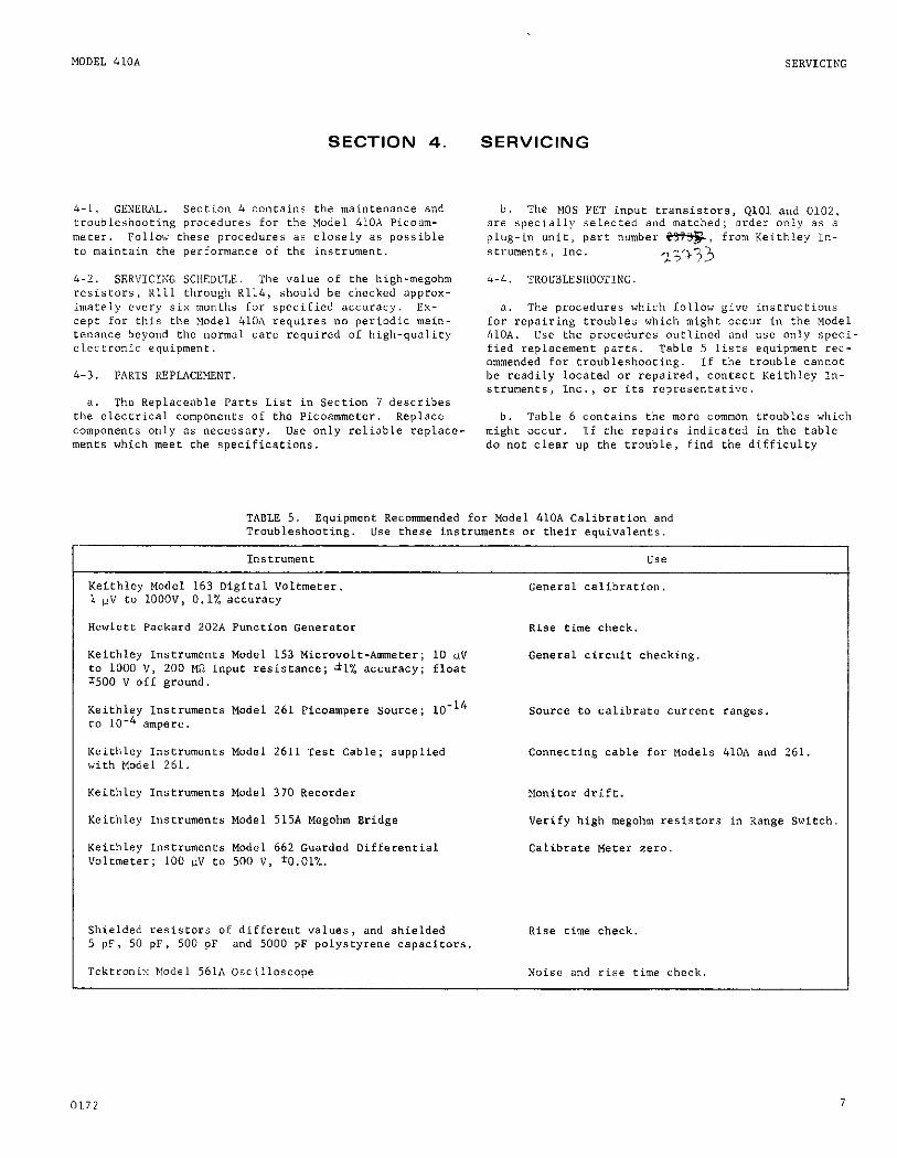
SECTION 4. SERVICING
SERVICING
4-2. SER”ICISG SCl,EOCI,E. The value Of the high-megotlm resistors, 11111 through K114, should be checked approx- imately every six months for specified accuracy. ES- cept for rtlis the Yodel 4101, requires “0 periodic main- tenance beyond the normal care required Of high-quality electronic equipment.
4-3. PARTS REPLACEMENT.
a. The Replaceable Parts LiSf in section 7 describes the electrical campanenes of the Picoammecer. Replace companenrs only as necessary. Ike only reliable replace- ments which meet the specifications.
3. The procedures which follow give instructions for repairing troubles which might occur in rhc Model 410A. “se the procedures outlined and use only speci- fied replacement parts. Table 5 Lists equipment ret- ommended for troubleshooting. if the Lrouble cannot be readily located or repaired, contact Keifhley In- Str”“entS, Inc., or its representative.
b. Table 6 contains the more common troubles which might occur. If the repairs indicated in the cable do not clear up the trouble, find the difficulty
Instrument “SC?
Keiehley Model 163 Digital Voltmeter 1 0” to 1000”, 0.1% accuracy
Keithley Instruments Model 153 Microvolt-Ammeter; 10 vv co 1000 v, 200 MR input resistance; ;fl% accuracy; float $500 ” off ground.
Keithley Instruments Model 261 Picoampere Source; 10-l’ to 10-4 ampere.
Keithley Instruments Model 370 Recorder
Keirhley Instruments Model 515A Megohm Bridge
Keithley Insfruments Model 662 Guarded Differential Voltmeter; 100 uv to 500 V, *O.Ol%.
Shielded resistors of different values, and shielded 5 pr, 50 PF, 500 pF and 5000 pF polystyrene capacitors.
Tektronix Model 561A oscilloscope
General calibration.
Rise rime check.
General circuit checking
Connecting cable for Models 410.A and 261.
Monitor drift.
Verify high megohm resistors in Range Switch.
Calibrate lacer zero.
Noise and rise time check.
0172 7

SERVICING
through a circuit-by-circuit check, such as given in paragraph 4-5. Refer to circuit description in Section 3 to find the more critical companents and to determine their *unction in the circuit. The complete circuit schematic, ?2547E, is in Section 7.
4-5. PROCEDURES TO GUIDE TROUBLESHOOTING.
a. If the instrument will not operate, check ehe power supplies. The typical voltage values, gi”e” on the schematic, are referenced to chassis ground. Make measurements with the Model 153 Microvolt Ammeter.
b. At times, the meter will not zero on any ran&e with the METER Switch in the ZERO CK position. If this occurs, adjust the front panel ZERO ADJ. Control or, if necessary, the Coarse Zero Poten!ziomeeer, R120, located on the PC Board. If this does not work, in- spect all PC boards for a possible break in the tapes. If these appear all right proceed with step c.
C. Amplifier.
1. To check the amplifier, disconnect rhe feed- back loop by removing Ql06, 0102, Dl05 and R.130 from rbe PC board. Check diodes Dl02 and Dl05
MODEL 410A
2. Connect a Model 153 between the bases of QlO3 and Q104. Adjust the Coarse Zero Potentiometer, Ri20, and the front panel ZERO ADJ. Control for a null (it may be difficult to reach a steady null; however, it is sufficient to be able to swing through zero in a smooth manner). If this is not possible, remO”e QlO3 and Q104 from the circuie and repeat the same process. If null can now be reached, replace Q103 and Q104. If it cannot be reached, QlOl and Ql02 are faulty.
3. Check the next stage, QIO5, by placing a Model 153 from the collector end of R129 to ground. Ad- just the Model 410.4 Zero Controls for null. If this cannot be accomplished, check DlOl for a possible open by shorring it with a clip lead. If null can now be reached, DlOl is open and should be replaced. If null cannot be reached, replace Q105.
4. If null can now be attained at the collector of QlO5, rbe trouble is in the output stage and Q106 should be replaced. If this does not cure the trouble, carefully check all the diodes associaeed with the output stage - Dl02, Dl03, 0104 and DlO5
TABLE 6. Model 410.4 Troubleshooting.
Difficulty
Excessive zero offset
Probable cause I
so1ueian
Input transistors may be defective Check QlOl and 4102; replace if faulty.
Power supply voltage low Check power supply.
Excessive temperature fluctuations Check QlOl and Ql02; replace if faulty. or defecrive input transistors
cannot zero on any range
Meter off scale on one of range settings
Refer to paragraph 4-5. Refer to paragraph 4-5.
Faulty range resistor Check resistor; replace if faulty.
One range out of specification Defective range resistor Check resistor: replace if faulty.
8 0172
MODEL 410.4 CALIBRATION
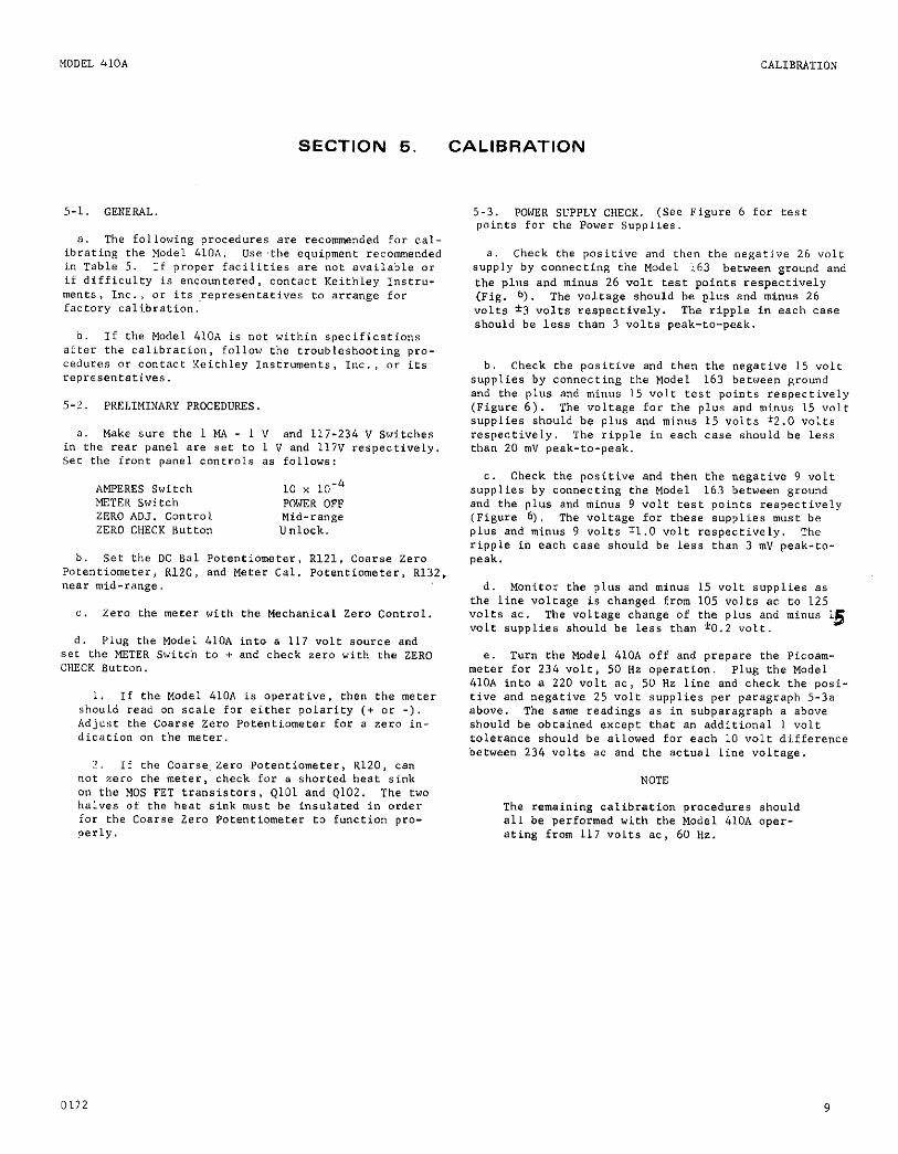
SECTION 5. CALIBRATION
5-1. GENERAL.
a. The following procedures are recommended for cal- ibrating the Model 410A. Use ,the equipment recommended in Table 5. If proper facilities a;e no? available or if difficulty is encountered, coneact Keithley ~nstru- merits, Inc., or its .representatives to arrange for factory calibration.
0. If the Model 41OA is not within specifications after the calibration, fallow the troubleshooeing pro- cedures or contact Keithley Instruments, Inc., or its representatives.
5-Y. PRELIMINARY PROCEDURES
a. Make sure the 1 MA - 1 V and 117-234 V Switches in the rear panel are see to 1 V and 117” respectively set the front panel controls as fallows:
HMPERES Switch 10 x 10-4 METER Switch POWER OFF ZERO AOJ. Control Mid-range ZERO CHECK Sutton Unlock.
b. see the DC B81 Potentiometer, R121, coarse zero Pacentiometer, RlZC, and Meter Cal. PoLentiometer, R132, near mid-range,
c. Zero the meter wifh the Mechanical Zero Coneral.
d. Plw the Model 410~ into a 117 volt eource and set the K&R Switch to + and check zero with the ZERO CHECK Button.
1 If the Model 410A is operative, then the meter should read an scale for either polarity (t or -). Adjust the Coarse Zero Potentiometer for a zero in- dication on the meter.
2. If the coarse.zero PatenLiometer, R120, can not zero the meter, check for a shorted beat sink on the MOS FET transistors, QlOl and Q102. The two halves of the heat sink must be insulated in order for the Coarse Zero Potentiometer to function pro- perly.
5-3. POWER SUPPLY CHECK. (See Figure 6 for test points for the Power Supplies.
a. Check the positive and then the negative 26 volt supply by connecting the Model 163 between ground and the pIus and minus 26 volt test points respectively (Hg. b). The voltage should be plus and minus 26 volts *3 volts respectively. The ripple in each caee should be less than 3 YOlt8 peak-to-peak.
b. Check the posieive and then the negative 15 volt supplies by connecting the Model 163 between ground and the plus and minus 15 volt fese points respectively (Figure 6). The voltage for the plus and minus 15 vole supplies should be plus and minus 15 volts *2.0 volts respectively. The ripple in each case should be less than 20 m” peak-to-peak.
c. Check the positive and then the negative 9 volt supplies by connecting the Model 163 between ground and the plus and minus 9 volt test paints respectively (Figure 6). the voltage for these supplies muse be plus and minus 9 volts il.0 volt respectively. The ripple in each case should be less than 3 mv peak-to- peak.
d. Monitor the plus and minus 15 volt supplies as the line voltage is changed from 105 volts ac to 125 volts ac. The voltage change of the plus and minus 15 volt supplies should be less than f0.2 volt.
e. Turn the Model 410.4 off and prepare the Picoam- meter for 234 volr. 50 Hz operation. Plug the Model 410.4 into a 220 volt ac, 50 Hz line and check the posi- tive and negative 25 volt supplies per paragraph 5-3a above. The seme readings as in subparagraph a above should be obtained except that an additional 1 volt tolerance should be allowed for each 10 volr difference between 234 volts ac and the actual line voltage.
NOTE
The remaining calibration procedures should all be performed with the Model 410A oper- ating from 117 volts ac, 60 Hz.
0172 9
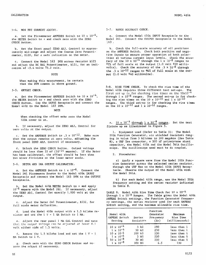
5-4. MOS FET CURRENT ADJUST.
a. set the Picoammeeer AMPERES Switch to 10 x 1W4. the METER switch to + and check zero with the ZERO CHECK Button.
b. set the front panel ZERO AD.,. Control to approx- imately mid-range and adjust the Coarse Zero Potenti- ometer, R120, for a zero indication on the meter.
C. Connect the Model 163 DVM across resistor R.123 and adjust the DC BAL Potentiometer, R121, for an indi- cation of -5.4 “olrs +0.2 “olt.
NOTE
When making this measurement, be certain that the WI., co,,,,,,on is above ground.
5-5. OFFSET CHECK.
a. See the Picoammeter AMPERES Switch to 10 x 10e4, the METER Switch to + and check zero with the ZERO CHECK Button. Cap the INPUT Receptacle and connect the Model 41OA to the Model 163 WM.
NOTE
When checking the offset make sure the Model 410A CoYer is on.
b. If necessary, adjuse the ZERO ADJ. Conerol for zero voles at the outpnt.
C. Set the AMPERES Switch to .3 Y 10-12. Make sure that the output remains at zero “olts, adjusting the front panel ZERO ADJ. Control if necessary.
d. Unlock the ZERO CHECK Button. Output voltage should be less than 33 m” (lo-l4 ampere). If the Meter has been calibrated, the offset should be less than two minor divisions on the lower meter scale.
5-6. METER AND LMA OUTPUT CALImATION.
a. see the AMPERES Switch to 1 x 10⁻⁶. Connect the Model 261 Picoampere Source to the Model 41OA INPUT ~ecepeacle and connect the Model 163 D”M to the OUTPUT ReCeptaCle.
b. Set the Model 410A METER Switch to + and apply 10-e ampere with the Model 261. If necessary, adjust the ZERO ADJ. Control for exactly 1.000 “olt at the output.
C, Adjust the Meter Cal Potentiometer, R132, for full scale meter deflection.
d. Load the Model 41OA output with a 1.5 kilohm re- sistor and see the 1 V - 1 MA Switch to 1 MA.
e. Adjust the rear panel 1 Ew CAL Control and note that the output voltage can be adjusted at least 0.1 volt either side of 1.5 volts.
f. remove the 1.5 kilohm load and set the 1 V - 1 MA Switch to 1 V.
g. Check zero with the ZERO CHECK Button and re- zero the olitpue if necessary.
10
MODEL 410h
5-7. RANGE ACCURACY CHECK
a. Cmnect the Model 410.4 INPUT Receptacle to the Model 261. Connect the O”TP”T Receptacle fo the Model 163
b. Check the full-scale accuracy of all positions on the AMPERES Switch. Check both positi”e and nega- tive inputs to ensure proper operation of both palar- ities at various current input levels. Check the accu- racy of the 10 x 1O-4 through the 1 x 10-S ranges to i2% of full scale af the output (1.0 volt *20 milli- volts). Check the accuracy of the .3 x 10.8 rhrough the .3 x lo-12 ranges to *4% of full scale at the out- out (1.0 volt T40 milli”olts).
5-S. RISE TIME CHECK. To check the rise time of the \lodel 410A requires three different test set-ups. The first set-up is for checking rise times on the 10~10‘~ through 1 x 10-S ranges. The second set-up is for check. ing the rise times on the 10 x 10-10 and 1 x 10⁻¹⁰ ranges. The third set-up is for checking the rise times on the 10 x lo-l2 and 1 x lo-l2 ranges.
a. 10 x 10-4 through 1 x 1O-8 w. Set the tell fixture up as illuserated in Figure 5.
1. Equipment used (Refer to Table 5): The Model 202A Function Generator, six shielded resistors rang- ing in value from 3 kilohms to 300 megohms (See Table 8), a UHF Tee connector, a 500 pF polystyrene shunt capacitor, the Model 41OA and the Model 561A Oscilla- scope. The oscilloscope used mutt be dc coupled.
2. Procedures:
a) Apply a square wave from the Model 202A Func- tion Generator across the selected series resistor, through the W Tee to the Model 4lOA INPUT Recep- tacle. Observe the output of rhe Model 410A with the Model 561A.
b) For each Model 410A range, use the Model 202A frequency setting and the series resistor indicated in Table 8.
TABLE 8. Model 410A Rise Time Check for 10 x 10e4 Through 1 x 10-S Ranges. The Table gives the Model 41OA AMPERE Switch settings, the Function Generator frequen- cy settings, the series resistor used for each AMPERE Switch setting, and the maximum allowable rise time.
Funcrio" Model 410A Ge”eratOX Maximum
AMPERE Switch Series Frequency Rise Time setting Resistors (HZ) (milliseconds)
10 x 10-4 3 kfi 250 less than 1 1 x 10⁻⁴ 30 k!l 250 less than 1
IO x 10-6 300 kn 250 less than I 1 x 10⁻⁶ 3 MCI 250 less than I
IO x 10-8 30 Ml? 250 less than 1 1 x 10⁻⁸ 300 MC? 2.5 130
0172

MODEL 410A CALIBRATION
-10 b. 10 Y 10 & 1 -10 x 10 m. Set this test fixture up as illuSerafed in Figure 5, except use a 5000 PF shunt capacitor end Substitute a shielded 50
1. Equipmenr Used: This test set-up uz.eS the Same equipment of the previous set-up with the exception of the 5000 pF and 50 pF palysytrene capacitors. The 50 pF series capacitor in this ret-up served a simi- lar function as the series re~i~for~ in the previous test set-up.
2. Proceduree:
a) Apply a triangular wave from the Model 202.4 across the capacitor, through the UHF Tee to the
r yodel 410.4 INPUT receptacle. Monitor the Model 410A output with the Model 561A. Use the proper Model 202A frequency setting as indicated in Table 9.
b) Adjust the Model 202A amplitude control as needed to obtain 2 volt?. peak-to-peak at the Model 41OA output. Check the 10 - 90% rise rime to the figures shown in Table 9.
TA8l.E 9. Model 410A Rise Time Check for 10 x 10el" and 1 x lo-lo Ranges. The Table gives the Model 410A AMPERE Switch setrings, the Function Generator frequency set- tings, and the maximum allowable rise time.
Model 410A Function Generamr Maximum AMPERE Switch Frequency Rise Time
Settine. (HZ) (milliseconds)
2.5 100 1.0 400 I
.
c. 10 x lo-l2 and 1 x lo-l2 w. Set this test fixture up as in paragraph 5-8b above except use a 500 pF shunt capacitor and a 5 pF series capacitor berween the Function venerator and the WE Tee.
1. Equipment Used: Except for the values of the capacitors mentioned above, this set-up USES the fame equipment as in paragraph 5-8b.
2,. Procedures:
“1 Set the Picaammeter AMPERES Switch to 10 x
10. 2. Apply a 0.5 Hz triangular wave from the Model 202A ecross the capacitor, through the UHF Tee to the Model 410A INPUT Receptacle.
b) Adjust the Model 202A amplitude control as needed to obtain 2 volts peak-to-peak at ehe Model 410A output. Check the 10 _ 90% rise time on the Model 561A. It should be less than one second.
c) Set the Picoammeeer AMPERK+ Switch to 1 x 10-12. Apply a 0.05 Hz triangular uave from the Model 202A to rhe Model 410A.
d) Adjust the Model 202A amplitude control to obtain 2 voles peak-to-peak at the Model 41OA out- put. Adjust the slide on resistor RI14 to obtain between 2 to 2.5 secondr 10 - 90% rise time.
e) Replace the 500 pF shunt cap~cimr with a 5000 pF shunt capacitor.
f) Apply a triangular signal from the Function Generaear to the Model 4lOA as listed in Table 10. Adjust the Model 202A amplitude control as needed to obtain 2 voles peak-to-peak at the Model 410A output. Check the 10 - 90% rise times to the fig- ures in Table 10.
FIGURE 5. lest Set-up for Model 410A Rise Time Checks on all ranges. Make Sure rhe series reSiStor or capacitor, and the UHF Tee and shunt capacieor are properly shielded.
0172 11
CALIBRATION MODEL 410A
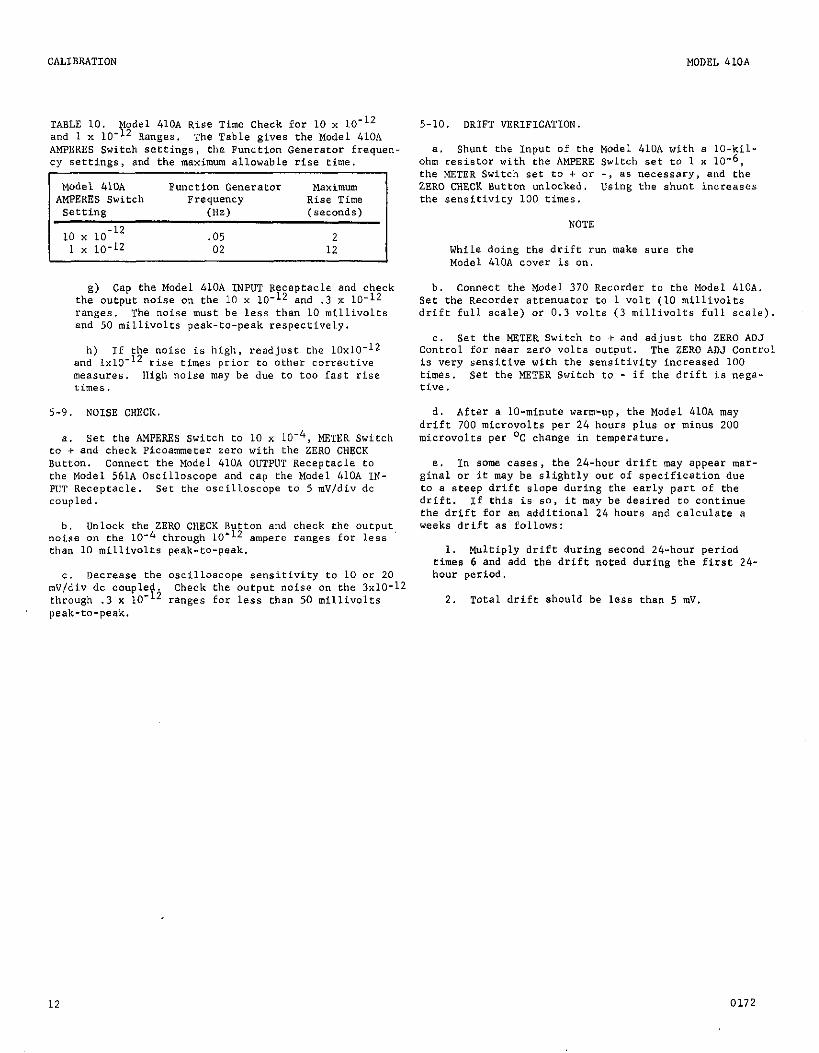
TABLE 10. Model 410A Rise Time Check for 10 x 10-12 and 1 x 10-12 Ranges. The Table gives the Model 410A AMPERES Switch settings, the Function Generator frequen cy settings, and the maximum allawable rise time.
~~
g) Cap the Model 410A INPUT Receptacle and check the output noise on the 10 x lo-l2 and .3 x lo-l2 ranges. The noise muet be less than 10 millivolts end 50 millivolts peak-to-peak respectively.
h) If the noise is high, readjust the 10~10~1~ and 1x10-” rise times prior to athee corrective measures. High naise may be due to too fast rise rimes.
5-9. NOISE CHECK.
a. Set the AMPERES Switch to 10 x 10m4, METER Switch to c and check Picoammeter zero with the ZERO CHECK Sutton. Connect the Model 410A OUTPUT Receptacle to the Model 561A Oscilloscope and cap the Made1 &lo.& IN- PUT Receptacle. Set the oscilloscope to 5 mV/div dc coup led.
b. Unlock the ZERO CHECK Button and check the o”tput noise on the 10m4 through 10-l’ ampere ranges for less than 10 millivolts peak-to-peak.
C, decrease the oscilloscope sensitivity to 10 or 20 1”
5-10. DRIFT vERIFICATION.
a. Shunt the Input of the Model 410.4 with a lo-kil- ohm resistor with the AMPERE Switch set to 1 x 10⁻⁶, the METER Switch set to + or -, es necessary, and the ZERO CHECK Buttcrr unlocked. Using the shunt increases the sensitivity 100 times.
NOTE
While doing the drift run make sure the Model 410A ccwer is on.
b. Connect the Model 370 Recorder to the Model 410.4. Set the Recorder eteenuat~r to 1 volt (10 millivolts drift full scale) or 0.3 volts (3 millivolts full scale).
C. Set the METER Switch to + and adjust the ZERO AoJ Control far near zero volte ~ucput. The ZERO ADJ Cantrol is very sensitive with the sensitivity increased 100 times. Set the METER Switch to - if the drift is negs- tive.
d. After a lo-minute warm-up, the Model 410A may drift 700 microvolts per 24 hours plus or minus 200 microvoles per ‘C change in temperature.
e. In ecrne cases, the 24-hour drift may appear mar- ginal or it may be slightly out of specification due to e steep drift elape during the early pert of the drift. 1f ehis ie so, if may be desired LO continue the drift for e,, additional 24 hours and calculate e weeks drift as fallaws:
1. Multiply drift during second 24-hour period times 6 and add the drift noted during the first 24- hour period.
peak-to-peak.
Check the output noise on the 3x10⁻¹‘ ranges far less than 50 millivolts 2. Total drift should be less than 5 m”.
12 0172

MODEL 41OA CALIBRATION
I
FIGURE 6. Chassis, Top view.
0172 13

CALIBRATION MODEL 410A
FIGURE 7. Component Layout, Pc184.
14 0172

MODEL 410A ; ACCESSORIES
SECTION 6. ACCESSORIES
6-l. GENERAL. The following Keithley accessories 6-2. OPEPATlNG INSTRUCTIONS. A separate Instru~eion can be used wifh the Model 410A to provide additional Manual is supplied with each accessory giving complete convenience and versatility. operating information.
I
Model 6106 Electrometer Connection Kit
Description:
The Model 6106 contains a group of the most useful leads and adparecs far low current measurements. All components are housed in a rugged carrying case with individual compartments.
Parts List:
Description It=” NO.
Keirhley Part No.
Cable, 30”, UHF to clips 1 1907x Cable, 24”, UHF to UHF 2 18265C Connector, UHF to UHF B-5 Adaptor, UHF to BNC :, a-115 Adaptor, UHF to BNC 5 G-172 Adaptor Tee, UHF to UHF 6 cs-171 Adaptor, Binding Post 7 190718
The two cables (Items 1 and 2) are coaxial shielded leads useful for connections where low noise is essen- tial. The 24” cable (Item 2) can be used to intercon- nect two instruments having UHF receptacles. The 30” cable (Item 1) can be used to connect to the circuit under test through the use of clip leads. A binding post adapter gives easy access to the electrometer “high” rerminal. Two UkB’ female couplers (Item 3) permit cables to be connected togefher. The UHF “tee” connector simplifies galvanometric current measurements when using a current source and electrometer or pico- ameter. Adapters (items 4 and 5) are useful far con- version from LIHF to BNC terminations.
Model 261 Picoampere Source
Oeseription:
The Model 261 is an accurate picoampere current source with 3 digit resolution. The output ranges are lo-l4 ampere to 1.1 x 10m4 ampere, positive or negative, in eight decade ranges. Accuracy is rated from 1.25% to 21.6% exclusive of input drop considerations.
Application:
‘The Model 261 is a secondary standard for use in cali- brating picoameters and electrometers. It can also be used as an accurate current source for zero suppression and for galvanometric measurements.
0172 15

ACCESSORIES MODEL 41OA
Models 24OA, 244, 245, 246 Voltage Supplies
Description: Output Ranges:
Keiehley voltage supplies are highly-stable, low-noise Model No. Voltage power supplies for voltages up to 23100 volts dc. 240A 0 to i12oov
244 -200 to -2200" 245 0 to ~2100"
Application: 246 0 to i31oov
Keithley voltage supplies are commonly used with pico- ameters in the measurement of resistance, light levels (photomultipliers), and radiation intensity (ion chambers). These high voltage supplies have been designed to operate with the Keithley line of electrameters, picoameters and resisrivity accessories. A typical application is shown using the Model 414s (or 414A) and the Model 240A in a photomultiplier experiment.
Model 4104 Electronic Trip Model 4109 Polarizing Supply
The Model 4104 is an electronic trip installed in the The Model 4109 provides +300 volts at 1 mA for appli- p'coameter to provide automatic current control. cations requiring a stable voltage source. The Model Combinations of high, low, + polarity, and latching 4109 can be ordered installed in the picoameeer if is available. desired.
16 0172
MODEL 410A ACCESSORIES
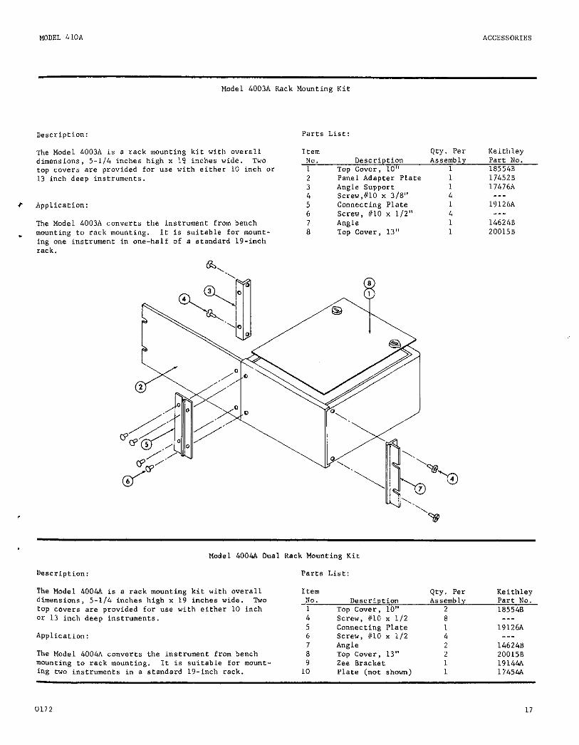
Model 4003A Rack Mounting Kit
Description: Parts List:
The Model 4003A is a rack mounting kit with overall dimensions, 5-l/4 inches high x 19 inches wide. TWO top cover‘s are provided far use with either 10 inch or 13 inch deep instruments.
t Application:
The Model 4003A converts the instrument from bench . mounting to rack mounting. It is suitable for mount-
ing one instrument in one-half of a standard 19-inch rack.
1eem NO. Description 1 Too Cover. 10" 2 Panel Adagter Plate 1 174520 3 Angle support 1 17476A 4 Screw,#lO x 3/S" 4 ___
5 Connecting Plate 1 19126A 6 Screw, #IO x l/Z" 4 ___
7 Angle 1 146248 8 Top Cover, 13" 1 200158
oty. Per Keithley Assembly Part NO.
1 185548
Model 4004A Dual
Description:
The Model 4004A is B rack mounting kit with overall dimensions, 5-l/4 inches high x 19 inches wide. Two top covers are provided for use with either 10 inch Or 13 inch deep instruments.
Application:
The Model 4004~ converts the instrument from bench mounting to rack mounting. It is suitable for mount- ing two instruments in a standard 19-inch rack.
Rack “ou”ei”g Kit
Parts List:
Item Qey. Per Keithley -NO. Description Assemblv par-c NO.
1 Top Cover, 10" 2 185548 4 Screw, 010 x l/2 8 --- 5 Connecting Plate 1 19126A 6 Screw, #lo x 112 4 ---
7 Angle 2 146248 8 Top Cover, 13" 2 200158 9 Zee Bracket 1 19144.4
10 Plate (not shown) 1 17454.4
0172 17
REPLACEABLE PAR+S MODEL 410A
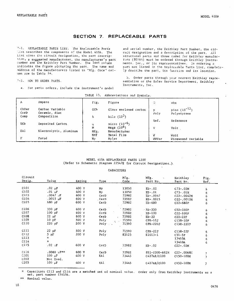
SECTION 7. REPLACEABLE PARTS
7.1, REPLACEABLE PARTS LIST. The Replaceable part's !.ist describes the components of the mdel 410~. me List: vi"es the circuit designation, the pare descrip- tion, a suggeswd manufacturer, ehe manufacturer's part number Brld the Keithley part Number. The last column idicates the figure picturing the part. The name and address of the manufacturers listed in "Mfg. Code" col- LLnm are in Table 14,
7.:9, HOW TO ORDER PflllTS
and serial number, the Keithley Pare Number, the cir- cuit designation and a description of the pare. All structural parts and those coded for Keithley manufac- ture (80164) must be ordered throu8h Keithley ~nscru- rents. Inc., or its represencncives. In ordering a part not listed in the replaceable Parts List, complete- ly describe the part, its function and its locntion.
b. Order parts through your nearest Keithley repre sentative or the Sales service Deonrfment. Keithle" Instruments, 1°C.
a. ?or parts orders, include the inserunent's model
TABLE 13. Abbreviations and symbols.
A Ampere Fig. Figure ohm
CbVar cartan Variable GCb Glass enclosed carbon p pi.20 (lo-'*) cem ceramic, disc POlY POly.Yeyrene camp Composition k kilo (103)
Ref. Reference DCb Deposited Carbon
L micra (10-6) Vega (106) " Volt
EAl Electrolytic, Aluminum Mfg. MGill"f~Ct"i-~r MC Metal Film w watt
F Farad MY Mylar WW"a= Wirewound "ariable
MODEL 410A REPLACEABLE PARTS LIST (Refer to Schematic Diagram 225478 far Circuit Designations.)
CAPACITORS
Rating Mfg. Code
Mfg. Pare NO.
Keithley Part No.
Fig. Ref.
Cl01 Cl02 Cl03 Cl04 Cl05
Cl06 Cl07 Cl08 Cl09 Cl10
Cl11 Cl12 Cl13 Cl14 CL15
.02 uF
.01 ;F ,004, SF .0015 Is 680 PF
330 oF 100 ;F 22 PF 10 pF 220 pF
22 p* 5 pF Y * .02 ;rF
.0068 UT?** 100 VF Not Used. 100 VF
400 ” 400 " 600 " 600 v 600 "
600 V 600 v 600 v 500 v so0 v
500 " 200 "
600 "
600 V 400 v
13050 13050 72982 72982
.72982 ED-330 72982 ED-100 12982 ED-22 71590 CPR-10J 71590 CPR-220J
71590 CPR-22J 83125 E1013-1
72982 ED-.02
72982 851-Z5"0-682M 73445 C437AR/GlOO
ED-.02 ED-.01 ED-.0047 ED-.0015 ED-680
C437ARIGlOO
C73-.02M 6 C73...01M 6 C22-.O047M 6 C22-.0015M 6 C22-680P 6
C22-33OP 6 c22-1OOP 6 c22-22P 6 C138-1OP 6 C138-220P 6
C138-22P 6 c31-5P 6 1341OA 6 1341OA 6 C22-.02M
C22-.006811 7 C150-100M 7
C150-100M 7

MODEL 4LOA REPLACEABLE PARTS
RESISTORS
circuit Desig. Rating Type
Mfg. Mfg. Keithley Fig. Code Part NO. Part NO. Ref.
RlOl R102 R103 R104 R105
RI06 RI07 ~108 RI09 Ill10
Rlll R112 RI13 RI14 RI15
109 n 1010 n 1011 9 1012 n 1 Mn
R116,:9: 100 kR R117 2 kcl RI18 700 0 R119 300 0 R120 1 lcn
8121 RI22 R123 R124 R125
R126 RI27 R128 RI29 R130
R131 R132 R133 R134 R135
R201 R202 R203 R,204 R205
R206
Circuit Mfg. Keithley Fig. bsig. x’umlJcr ^ coae Parr NO. Ref.
5 kR 9 ki? 18 lc* 2 !a 18 kR
15 kR 2.2 !4 680 ~2 4.7 k0 1.2 kn
1 kn
27 kn 390 n 820 0 820 n 820 n
820 n
1%. 112 w I%, l/2 w l%, l/2 w I%, 1 w I%, l/2 w
I%, l/2 w l%, l/2 w l%, l/2 w l%, 1 w l%, 2 w
3% 3% 3% 3% l%, l/2 w
lO%, l/4 w 112%. l/2 w l/2%, l/2 w l/2%, l/2 w lo%, 5 w
20%, 2 w l%, l/2 w l%, l/2 w 20%, 0.2 w l%, l/2 w
IO%, l/2 w lo%, l/2 w lO%, l/2 w lo%, l/2 w IO%, l/2 w
l%, l/2 w 20%, 2 w U2%, l/Z w l/2%, l/2 w lO%, 5 w
l/2%, l/2 w
lo’/,, l/2 w lO%, l/2 w lO%, l/2 w lO%, l/2 w lo%, l/2 w
lO%, l/2 w
DCb 91637 DCF l/2 DCb 91637 DCF l/2 DCb 07716 DCC EPOXY 91637 MMF-1 DCb 91637 DCF l/2
DCb DCb DCb DCb DCb
07716 07716 91637 91637 91637
DCC R12-1M DCC R12-3M DCF 112 R12-IOM DC-1 R13-30M DC-2 4l?udQw
GCb 63060 GCb 63060 GCb 63060 GCb 63060 DCb 07716
COlIp MtF MC MtF ww”ar
01121 07716 07716 07716 71450
ww”Z DCb DCb Cmp” DCb
71450 07716 07716 71450 07716
COtlIp camp camp camp COUIP
01121 01121 01121 01121 01121
DCb 07716 ww”ar 71450 MtF 07716 MtF 07716 ww”ar 71450
MZF 07716
a1121 01121 01121
.01121 01121
01121
m-1 Rx-1 Rx-1 Rx-1 DCC
CB CEC CEC CEC AW
INS-115 DCC DCC 70 DCC
ES ES EB EB HB
DCC INS-115 CEC CEC AW
CRC
EB EB ELI EB ES
EB
R12-3K R12-10K x12-30K K150-100K R12-3OOK
R76-100K R61-2K R61-700 R61-300 RP34-1K
RP50-5K 7 R12-9K 7 R12-18K 7 RP31-2K 1 R12-18K 7
Rl-15K 7 RI-2.2K 7 ~1-680 7 RI-4.7K 7 R3-1.2K 7
R12-2K 7 RPSO-2K 7 R61-1K 7 R61-1K 6 RP34-1K 2,6
~61-1K 6
Rl-27K Rl-390 Rl-820 Rl-820 Rl-820
Rl-820
QlOl*;i 80164 4102** 80164 Q103 80164 21675.A 7 Q104 80164 21675A 7 QlO5 2N3904 04713 TG-47 7
Q106 NPN, case TO-66 40513 02735 ** Reolace Q101. Q102 or RI16 by ordering Plug-in board 23735.
TG-122 7
0476 19
REPLACEABLE PARTS MODEL 410A
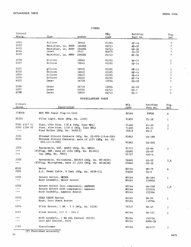
DIODES
circuie Desig.
DLOl "102 0103 0104 D105
0106 0107
D?Ol D?"? 0203 "204 0205
0206 0207 D208
Mfg. Keiehley Type N"Ulber Code
Fig. Part NO. Ref.
Silicon IN645 01295 RF-14 7 Rectifier, IA, 800" IN4006 04713 RF-38 7 Rectifier, LA, 800V 1~4006 04713 RF-38 7 zener "R47 84970 DZ-30 7 Rectifier. Lt. 800" 1N4006 04713 RF-38 7
Silicon lN645 01295 RF-14 7 Silicon lN645 01295 w-14 7
$ilicon lN645 01295 RF-14 Silicon
7 lN645 01295 RF-14 7
Silicon lN645 01295 RF-14 7 Silicon IN645 01295 RF-14 7 zener lN718 12954 DZ-18 7
Ze"er 1N718 12954 DZ-18 7 zener IN935 04713 DZ-7 7 Ze"er 1N935 04713 DZ-7 7
MISCELLANEO"S PARTS
Mfg. Keiehley Fig. Code Part No. Ref.
218508 MOS FET Input Plug-in Card
DS201 Pilot Light, Neon (Mfg. No. 2190)
F201 (117 ") Fuse, slow blow, l/8 A (Mfg. type MOL) F-201 (234 ") Fuse, slov blow, l/16 A (Mfg. type MDL)
___ Fuse Holder (Mfg. No. 342012)
JlOl PlOl
Printed Circuit CcmCact~ (Mfg. No. 02-005-113-6-200) Printed Circuit Contacts, mate of JlOl (MFg. No. OZ-
005-111-5-200)
5102 --_ ---
.7103 --_
Ml01 P201
SlOl
Receptacle, DHF, INPUT (Mfg. No. 6804) (F)Plug, UHF, mate of 5102 (Mfg. No. 83-822)
Cap (Mfg. No. 7901)
Receptacle, Microphone, OUTPUT (Mfg. No. 80-PC~F) (F)Plug, Microphone, mate of 5103 (Mfg. NO. 80~MCZM)
Meter A.C. Power Cable, 6 feet (Mfg. Na. 4638-U)
Rotary Switch, METER Knob Assembly, Meter Switch
91737 CS-64 02660 cs-49 91737 CAP-4
02660 m-32 02660 CS-32
80164 m-79 93656 co-5
80164 SW-264 80164 21660A
5102 Rotary Switch less components, AMPERES 80164 SW-268 Rotary Switch with components, Amperes 80164 221978 Knob Assembly, Amperes Switch 80164 22220A
5103 ZERO CHECK Button 80164 SW-94 Knob, Zero Check Buteon 80164 14376A
s104
SZO1
___
Slide Switch, 1 MA - 1 " (Mfg. No. 6326)
Slide Switch, 117 v - 234 "
Knob Assembly, 1 MA CAL Control (~135) zero ADJ Control, R124
79727
80164
80164
T201 Transformer
(P) Furnished accessory. 20
80164
SW-45
SW-151
1637% RP66-2K
m-112
80164 2m5
91802 PL-28
71400 71400 75915
m-20 NJ-21 m-3
91662 cs-199
91662 m-200
2
236
6
1
136
1
2
2
7
0476
MODEL 410A REPLACEABLE PARTS
TABLE 14. Code List of Suggerred Manufacturers. (Based on Federal Supply Code for Manufacturers, Cataloging Handbook H4-1.)
01121
01295
02660
02735
04713
07716
12954
13050
63060
71279
7 1400
71450
Allen-Bradley Carp. 1201 Saueh 2nd Street Milwaukee, Wis. 53204
Texas InstrunlentS, Inc. Semiconductor-Components Division 13500 North Central Expressway Dallas, Tex. 75231
Amphenol Corp. 2801 South 25th Avenue Broadview, Chicago, Illinois 60153
Radio Corp. of America Commercial ReceiL Tube and Semiconductor Division Somerville, N.J.
Motorola, 1°C. Semiconductor Products Division 5005 Eaet McDowell Road Phoenix, Arizona 85008
International Resistance Co. 2850 Mt. Pleasant Burlington, Iowa 52601
Dickson Electronics Corp. 302 S. Wells Fargo Avenue Scottsdale, Ariz.
Potter Co. Highway 51 N. weeso”, Miss. 39191
Vicroreen Instrument Co. 5806 Hough Avenue Cleveland, Ohio 44103
Cambridge Thermionic Carp 430 Concord Avenue Cambridge, Mass.
Bussmann Mfg. Div. of McGraw Edison Co. 2538 W. University St. St. Louis, MO.
cm Corp. 1142 W. Beardeley Avenue Elkhart, 1nd.
ring
71590
72982
73445
75915
79727
80164
83125
84970
91637
91662
91737
91802
93656
Centralab Division of Globe-Union, 1nc 932 E. Keefe Avenue Milwaukee, Wis. 53212
Erie Technological Products, Inc 644 W. 12th Street Erie, Pa. 16512
Amperex Electronic Co. Division of North American Phillips Co., 1nc. Hicksville, N.Y.
Littlefuse, 1°C. 800 E. Northwese Highway Des Plainee, Ill. 60016
Continental-Wirt Electronics Carp Philadelphia, Pa.
Keith& Instruments, Inc. 28775 Aurora ~~~~ Cleveland, Ohio 44139
General InSteumentS carp Capacitor Division Darlington, S.C.
Sarkes Tarzian, Inc. E. Hillside Dr. Bloomington, Ind.
Dale Electronics, Inc. P.O. BOX 609 Columbus, Nebraska 68601
Elm carp. Willow Grove, Pa.
Gremar Mfg. co., Inc. 7 North Avenue Wakefield, Mass.
Industrial Device= Inc. 982 River Rd. Edgewater, N.J. 07020
Electric Cord Co. 1275 Bloomfield Avenue Caldwell, N.J.
0172 21

REPLACEABLE PARTS MODEL 4lOA
TABLE 15. Mechanical Parts List
Quantity Keithley Fig. Description Per Assembly Part NO. Ref.
1) Chassis 1 21659C 8
11) Front Panel
Top Cover Assembly
12) Cover, Sheet Mete.1
13) Screws
Handle Assembly
14) Handle
15) Screws 116-32 x 3/8” R.H. Slotted
Bottom Cover Assembly
2) Cover
3) Fastener
Feet Assembly
4) Feet
5) Ball
6) Screws M-32 x 3/S” Phillips, Pan Head
Tilt Bail Assembly
7) Bail
8) Right Assembly
9) Left Assembly
10) Screws $16-32 x l/4” Phillips, Pan Head
1 21767C
_-- 185538
1 17130D
4 ___
___ _--
1 HH-18
2 ___
___ 19298C
1 1934OB
2 FA-54
__- _--
4 FE-5
4 FE-6
4 _-_
--- _-_
1 17147B
1 192068
1 19205B
2 -..
8
9
22 0172
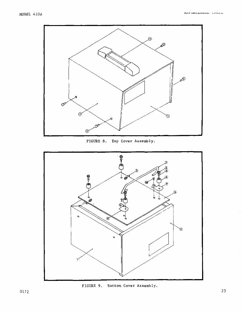
FIGURE 8. Top Cover Assembly.
0172
FIGURE 9. Bottom Cover Assembly. 23
-
-

KEITHLEY INSTRUMENTS, INC. 28775 AURORA ROAD
CLEVELAND, OHIO 44139 SERVICE FORM
MODEL NO. SERIAL NO. P.O. NO. DATE R-
NAME PHONE
COMPANY
ADDRESS CITY STATE ZIP
El : Describe problem and symptoms using quantitative data whenever possible (enclose readings, chart recordings, etc.)
(Attach additional sheets as necessary).
El Show a block diagram of your measurement system including all instruments connected (whether power is turned on or not). Also describe signal source.
' the instrument. List the positions of alJ controls and switches on both front and rear panels of
El Describe input signal source levels, frequencies, etc.
q List and describe all cables used in the experiment (length, shielding, etc.).
' for each. List and describe all other equipment used in the experiment. Give control settings
El Environment: Where is the measurement being performed? (Factory, controlled laboratory, out-of-doors, etc.) What power line voltage is used? Variation? Frequency? Ambient temperature? OF. Variation? OF. Rel. Humidity? Other
(If special modifications have been made by the user,
REV 0774

![Eee-III-electrical and Electronicmeasurements and Instrume [10ee35]-Notes](https://static.fdocuments.net/doc/165x107/55cf9d5e550346d033ad54ca/eee-iii-electrical-and-electronicmeasurements-and-instrume-10ee35-notes.jpg)