KeContact Load Management System manualSchematic overview (load management) Fleet solution The...
156
KeContact Load Management System manual
Transcript of KeContact Load Management System manualSchematic overview (load management) Fleet solution The...

KeContact Load Management
System manual

© KEBA 2014
Subject to alteration in the course of technical advancement. No guarantee is offered for the accuracy of the information provid-ed. All rights reserved.
All brand and product names are trademarks of their respective companies. Technical information in this document is subject to change without notice.
Document: Revision 2.00 / Release date: 29.08.2014 / Article no.: 91140
KEBA AG, Postfach 111, Gewerbepark Urfahr, A-4041 Linz, www.kecontact.com
Comments to this manual
In this manual you will find warnings against possible dangerous situations. The used symbols apply to the following meanings:
!
WARNING!
Indicates a potentially hazardous situation which, if not avoided could result in death or serious injury.
!
CAUTION!
Indicates a potentially hazardous situation which, if not avoided may result in minor or moderate injury.
CAUTION
Indicates a situation which, if not avoided could result in property damage.
Notes Notes on use of equipment and useful practical tips. Notices do not contain any information that draws attention to potentially dangerous or harmful functions.
Important information.
► Step of a sequence of operations.

3 / 156
List of changes
Version: V1.00 Date: 10.03.2014
Page Description
- Document created -
Version: V2.00 Date: 29.08.2014
- Revised complete document

Contents
4 / 156
Contents
1 Important information .................................................................................................................... 6
1.1 Safety instructions ................................................................................................................. 6 1.2 Intended use .......................................................................................................................... 6 1.3 About this manual.................................................................................................................. 7
2 System Overview ........................................................................................................................... 8
2.1 System components .............................................................................................................. 9 2.2 Scope of delivery ................................................................................................................. 10
3 System configuration information ............................................................................................. 11
3.1 General statement ............................................................................................................... 11 3.1.1 Supported communication protocols .................................................................... 12 3.1.2 Value for limitation of the power grid .................................................................... 13 3.1.3 Current allocation on multiple vehicles ................................................................. 14
3.2 Software architecture .......................................................................................................... 15
4 Hardware installation ................................................................................................................... 16
4.1 Common power line ............................................................................................................ 16 4.2 Provisions for flawless ISO 15118 communication ............................................................. 17 4.3 Ethernet wiring .................................................................................................................... 18 4.4 Wallbox numbering and Ethernet addressing ..................................................................... 19 4.5 DIP-switch settings .............................................................................................................. 20 4.6 KeContact M10 MMI menu ................................................................................................. 24
5 First time installation ................................................................................................................... 26
5.1 Installation menu ................................................................................................................. 27 5.2 Making a backup of the Compact Flash card ...................................................................... 29
6 Load management program ........................................................................................................ 30
6.1 Toolbar icons ....................................................................................................................... 31 6.2 Accessing the Load management program ........................................................................ 32
6.2.1 Login ..................................................................................................................... 33 6.2.2 Change password ................................................................................................. 34 6.2.3 Standard accounts and passwords....................................................................... 35
6.3 Home screen ....................................................................................................................... 36 6.4 Rebooting the system (Login required) ............................................................................... 37 6.5 Monitoring menu.................................................................................................................. 38
6.5.1 Charge Point Overview ......................................................................................... 39 6.5.1.1 General tab ........................................................................................... 39 6.5.1.2 Load Management tab ......................................................................... 42 6.5.1.3 Authorization tab................................................................................... 44 6.5.1.4 Metering and Power control tab ........................................................... 46 6.5.1.5 Power profile tab................................................................................... 49
6.5.2 Wallbox details ...................................................................................................... 51 6.5.2.1 Charging Overview tab ......................................................................... 51 6.5.2.2 Wallbox Settings tab ............................................................................. 54 6.5.2.3 Wallbox Operation tab .......................................................................... 56 6.5.2.4 Vehicle Overview tab ............................................................................ 58
6.5.3 Session overview .................................................................................................. 60 6.5.4 Session history ...................................................................................................... 63 6.5.5 Power usage ......................................................................................................... 65
6.6 Configuration menu ............................................................................................................. 66 6.6.1 Charge Point configuration ................................................................................... 68

Contents
5 / 156
6.6.1.1 General tab ........................................................................................... 68 6.6.1.2 Load Management tab ......................................................................... 71 6.6.1.3 Authorization tab................................................................................... 73 6.6.1.4 Metering and Power control tab ........................................................... 75
6.6.2 Wallbox configuration ........................................................................................... 79 6.6.2.1 Configure Wallbox tab .......................................................................... 79 6.6.2.2 Preconfigured Parameters tab ............................................................. 81
6.6.3 Power Profile configuration ................................................................................... 83 6.6.4 Edit Power Profile ................................................................................................. 87 6.6.5 View Power Profile ................................................................................................ 91
6.7 Installation menu ................................................................................................................. 92 6.8 Management menu ............................................................................................................. 96
6.8.1 Charging session .................................................................................................. 97 6.8.1.1 Charging session details .................................................................... 100
6.8.2 Manage Accounts ............................................................................................... 102 6.8.3 Select Account .................................................................................................... 104 6.8.4 View Meter Readings .......................................................................................... 105
6.8.4.1 Download meter readings .................................................................. 107 6.8.5 Manage White list ............................................................................................... 109
6.8.5.1 Configure White list entry ................................................................... 112 6.8.5.2 Import White list .................................................................................. 114
6.8.6 Manage NMKs .................................................................................................... 117 6.8.7 Housekeeping ..................................................................................................... 119
6.8.7.1 Start housekeeping ............................................................................ 119 6.8.7.2 Housekeeping parameters ................................................................. 121
6.9 Service menu .................................................................................................................... 123 6.9.1 Software Update ................................................................................................. 124 6.9.2 Firmware Update ................................................................................................ 126 6.9.3 Firmware versions............................................................................................... 128 6.9.4 Logfiles ................................................................................................................ 129 6.9.5 Diagnostics information ...................................................................................... 131 6.9.6 Digital Certificates ............................................................................................... 132 6.9.7 Manage Certificates ............................................................................................ 135 6.9.8 Upload Certificate ............................................................................................... 138 6.9.9 OCPP Host Interfaces ........................................................................................ 139
6.9.9.1 Configure Central system interface .................................................... 141 6.9.9.2 Configure Central system interface - Communication........................ 144 6.9.9.3 Configure Central system interface - Meter readings......................... 146
6.10 About screen ..................................................................................................................... 148 6.11 Error screen ....................................................................................................................... 149
7 Appendix ..................................................................................................................................... 150
7.1 Glossary ............................................................................................................................ 150 7.2 List of Abbreviations .......................................................................................................... 150 7.3 Data sheet power supply TDK-Lambda DPP50 ................................................................ 151
8 INDEX .......................................................................................................................................... 153

Important information
6 / 156
1 Important information
1.1 Safety instructions
!
WARNING!
Electrical hazard! For assembly and installation of the individual components (Charge Point, KeContact M10 etc.), please follow the instructions and safety instructions in the corresponding manuals.
1.2 Intended use
KeContact M10 Load Management is a system solution that allows the configuring and managing of up to 15 KeContact P20 (c-series) Wallboxes. A load management with different profiles can be realised with the KeContact M10.
Only KEBA approved devices (Wallboxes) may be connected to the closed KeContact LAN.
The correct use of the devices in all cases includes observing the ambient conditions for which the devices are developed.
The instructions contained in this manual must be precisely followed in all circumstances. Failure to do so could result in the creation of potential sources of danger or the disabling of safety features.
Apart from the safety instructions given in this manual, the safety precautions and accident prevention measures appropriate to the situation in question must also be observed.

Important information
7 / 156
1.3 About this manual
This manual is valid for
KeContact Load Management System Solution For whom is this manual? This manual is intended for use by qualified personnel1. These are persons with the relevant technical knowledge appropriate to the operations they are required to perform.
Project engineer
Skilled personnel and architects, who look for and select sites
Electrical installation company for the provision of electricity connection
Start-up technician
Operator of the devices
Service technician Documentation for further reading The following documents are to be observed depending on the system solution used:
Title
KeContact P20 Installation manual (for the specialist)
KeContact P20 User manual
Please also see: www.kecontact.com/vehicle-specifics.html This website lists known electrical peculiarities of EVs available and recommended system configurations for KeContact M10 Load management.
1 Persons who due to specialist training, expertise and experience as well as knowledge of current standards who are able to assess work carried out and possible hazards.

System Overview
8 / 156
2 System Overview
Charging multiple electric vehicles simultaneously, may exceed the capacity of the existing power connec-tion. To avoid an overload, simultaneous charging of multiple vehicles or at least the capacity of the individu-al vehicles must be managed and limited. This requires a solution that protects the grid from overload using smart load balancing and load scheduling and provides an efficient energy profile for each individual EV (electric vehicle).
The communication between electric vehicles (EV) and the KeContact M10 works according to IEC 61851-1 Mode 3 or, if supported by the EV, ISO 15118 high-level protocol. Schematic overview (hardware)
[M10]… KeContact M10 [KC P20]… KeContact P20 (c-series) Wallbox 1-15
[PS]… Power supply unit 24V
[Eth0]…Ethernet port for Installation, configuration and monitoring
[Eth1]…Ethernet port only for configuration and monitoring
[SW]… Ethernet switch
[PP]… Patch panel
Note: The DVI and USB ports on the KeContact M10 cannot be used to operate the device with a keyboard and a monitor!

System Overview
9 / 156
2.1 System components
The items listed below are not all included in the standard delivery (for details please see chapter "Scope of delivery").
KeContact M10
KeContact M10 The KeContact M10 is an industrial PC developed by KEBA AG. For more details please see “Kemro KeContact M10 Project Engineering manual”.
Power supply unit
Power supply unit 24V The rail mounted power supply is used to supply the KeContact M10.
Manufacturer's data: TDK-Lambda DPP50-24 Output voltage of 24V
For more details please see data sheet in the Ap-pendix.
KeContact P20 Wallbox (example)
KeContact P20 KeContact P20 c-series Wallboxes can be used in combination with the KeContact M10 load manage-ment. The wallbox is available in different variants. For more details please see "KeContact P20 Instal-lation manual".
Further required components:
Ethernet switch The Ethernet switch is used for the network connection of the individual Wallboxes to the KeContact M10.
Patch panel (CAT6) The Ethernet cable (Cat6 or higher quality) of the individual Wallboxes are applied on the patch panel and are connected to the Ethernet switch using a RJ45 patch cable.

System Overview
10 / 156
2.2 Scope of delivery
Component Delivery
KeContact M10
Compact Flash Card with installed software (already inside KeContact M10)
Backup Compact Flash Card – can be ordered from KEBA
Power supply unit TDK-Lambda DPP50-24 (24V) – can be ordered from KEBA
KeContact P20 c-series – can be ordered from KEBA
Component recommendations:
Ethernet switch Moxa EDS 205-A (5 Port)
Ethernet switch Moxa EDS 316 (16 Port)
Patch panel DIGITUS Desktop CAT 6, shielded DN-91608SD (8 Port)
External protocol switch Benedikt & Jäger „M10 PF W1 +GK +G2“
… delivery … optional available component

System configuration information
11 / 156
3 System configuration information
3.1 General statement
Purpose of the load management software
Cost-effective allocation of the available or allowed capacity (e.g. charging at night with low rates)
Load balancing
Optimized power distribution over several vehicles
Support for different communication protocols (low level IEC 61851-1, high-level ISO 15118) Schematic overview (load management)
Fleet solution The KeContact M10 is the server for a group of Charging stations (KeContact P20 Wallboxes) with a com-mon power line. KeContact M10 is the logical Charge Point. After a power failure or the loss of the communication connection, an automatic restart is performed. After-wards the running charging sessions are resumed. Plug & Charge with ISO 15118 The ISO 15118 protocol allows an intelligent charging of an Electric Vehicle. The charging station informs the vehicle when and at which price a certain energy amount is available. This data, the current battery level and the programmed finishing time is the basis for the vehicle to determine a cost optimized charging procedure. Basis functionality for charging Vehicles that offer only a functionality for charging according IEC 61851-1 are also supported. The authoriza-tion for charging can be carried out with a chip card (RFID).

System configuration information
12 / 156
Load Management The Load Management of the KeContact M10 distributes the available power line capacity to the connected vehicles. “First come, first serve” mode The vehicle gets the information of the available energy amount till the scheduled departure of the car via an ISO 15118 message. With this information, the vehicle calculates its charging procedure and reports it to the KeContact M10. The required energy amount will be reserved and is not available for other vehicles. "Equal allocation" mode This mode is used, if the communication with the vehicle is not possible via ISO 15118 protocol. In the case that there is not enough energy available for all vehicles, all vehicles get the equal amount. If this amount is too low (below the minimum-current for electric vehicles), the charging of the vehicles will be stopped for a certain period of time. A combined mode of both strategies is possible too. Authorization The KeContact M10 can manage a „White list“ with authorization codes. Vehicles (Vehicle ID with ISO 15118) and chip cards (RFID) can be added to this White list. Counter data The counter data are not calibrated. It is therefore at the discretion of the operator, whether the data is used for billing purposes.
3.1.1 Supported communication protocols
The load management software together with the KeContact P20 charging stations supports the exchange of information according to the following two standards:
Mode 3 Charging DIN EN 61851-1
Communication via DIN EN-61851-1 is a low level communication, between Charge Point and Electric Vehicle.
The limitation of the maximum possible charge current is done via the control pilot pin of the charging cable and is determined by the Wallbox (and the used cable). The Wallbox can regulate the charg-ing current by changing the PWM signal (Pulse Width Modulation).
ISO Charging ISO 15118
Communication via ISO 15118 is a high-level communication be-tween the Charge Point system and the Electric Vehicle using power line communication (PLC).
Moment, duration and charging current are negotiated between the KeContact M10 and the Electric Vehicle.
Initial settings must be made for the entire system: Which communication protocol shall be supported?
only Mode 3 (no high-level negotiation will be used)
only ISO communication (sole Mode 3 Electric Vehicles will not be able to charge)
combined mode charging (both, Mode 3 and ISO communication is a allowed)

System configuration information
13 / 156
3.1.2 Value for limitation of the power grid
A key value for the load management system is the total maximum available current (amps) of the power grid. This value represents the maximum power which can be supplied from the grid due to wiring and fuses.
Additionally the maximum total current can be reduced in dependence of time and day.
Example: The total maximum available current of the power supply line is 200 amps. Between 8 o'clock pm and 6 o'clock am there is no reduction. From 6 o'clock am till 8 o'clock pm there is a restriction to reduce the maxi-mum total current down to 120 amps.
Splitting between Mode 3 charging and ISO charging
The maximum total current for charging vehicles using Mode 3 communication or ISO communication can be split into two sections. For both groups of vehicles thus the available total current is reserved. The specified limit is dynamic, so vehicles with a Mode 3 communication can temporarily use free quota from the ISO range as long as there are free capacities. Vice versa this is not possible.
Example: 80 amps shall be reserved for Mode 3 charging. 120 amps shall be reserved for ISO charging.

System configuration information
14 / 156
3.1.3 Current allocation on multiple vehicles
The allocation of quotas follows the FIFO principle (First-in-First out), the charging current quotas for Mode 3 charging and ISO charging will be considered separately.
Section ISO charging If the total charging current of the EVs in the ISO charging group exceeds the limit, a new added vehicle (in the example "ISO4") will not be charged immediately. The vehicle "ISO4" is shifted for a later moment, until the consumption of the other EVs in the ISO group is going down and a quota is available. Section Mode 3 charging If the total charging current of the EVs in the Mode 3 charging group exceeds the limit, a new added vehicle (in the example “M3-1”) can be charged anyway, if there is a free quota in the ISO charging group. The vehi-cle “M3-1” will be charged until the ISO quota is needed again. If this happens, the charging current for the Mode 3 charging vehicles is reduced accordingly. ISO charging vehicles always have higher priority.

System configuration information
15 / 156
3.2 Software architecture
The KeContact M10 system contains the following main software components. Load Manager:
The load manager has the following responsibilities:
Controls and coordinates charging sessions for several vehicles on the separate charging stations (PDCs).
Is offering WEB services for the vehicle manager. These services allow the vehicle manager to initi-ate, start / stop charging sessions and other activities in response to the according requests of an electric vehicle using high-level communication.
All necessary activities and events that occur on the different charging stations (sockets) are man-aged and controlled by the socket manager (PDC manager). This way the socket manager assists the load manager in managing the separate charging sessions.
The load manager gathers the different information of the separate charging sessions, the used PDCs and the vehicle information and forwards those data to the charge point manager.
A core component of the load manager is the socket manager:
Represents the network of all connected PDCs and their status.
Forwards requests to the addressed PDCs, handles and reports status changes Vehicle Manager:
The vehicle manager has the following responsibilities:
Handles communication with vehicles using high-level communication (ISO 15118). Issues requests to the charge point manager and web service requests to the load manager in order to fulfil loading requests received by vehicles.
Establishes und closes secure communication sessions with vehicles. Charge Point Manager:
The charge point manager has the following responsibilities:
Manages the available power and assigns it to the PDCs (for Mode 3 charging) and to electric vehi-cles (for charging controlled by high-level communication).
Manages the HTML user interface for monitoring (status and current transactions) and entry of con-figuration data. Access to the monitoring pages of the charge point manager is allowed to anybody with proper network access.
Pages for configuration and system changes require a login. User Interface: The operator of the system connects with a web browser to the KeContact M10.

Hardware installation
16 / 156
4 Hardware installation
4.1 Common power line
The Wallboxes must be connected to one common power line with protective devices, otherwise the KeCon-tact M10 is not able to perform a correct load management according to the maximum available current.
A clustering of Wallboxes is not permitted! Be aware that each wallbox has to be secured by an individual RCD. Please see the “KeContact P20 Installation manual” for further details about installation.
Common power line – schematic overview
DO NOT USE multiple power lines!

Hardware installation
17 / 156
4.2 Provisions for flawless ISO 15118 communication
Installation recommendations when using more than one PLC Wallboxes. PLC blocking filters: If the vehicles are using ISO 15118 without SLAC mechanism (automatic pairing function), it is recommend-ed to install PLC blocking filters in the supply line of the PLC Wallboxes. This avoids communication trouble when charging two vehicles at the same time. Suitable PLC blocking filters can be ordered from KEBA.
Network Membership Key’s (NMKs) If the NMKs of the vehicles are different, PLC blocking filters are not required! The NMK of a vehicle can be changed with the “KEBA - EV Connection Assistant” software that can be downloaded from www.kecontact.com.
Schematic overview
Additional information With Public NMKs you are able to connect to devices in the whole network supported with PLC modems in the Wallboxes. Private NMKs are useful to connect to one device specified in the network.

Hardware installation
18 / 156
4.3 Ethernet wiring
For details about installing and connecting the components, please refer to the individual compo-nent manuals (KeContact P20 Installation manual, Installation manual of your Ethernet switch and patch panel). Use the LSA+® terminal block [ETH1] for the Ethernet connection and NOT the RJ45 port.
In any case the KeContact LAN must be designed as a closed network without direct public access.
Only the KeContact M10 can be connected via the Ethernet port [ETH1] to a public LAN (eg, corporate network).
The individual Wallboxes are wired to the patch panel using a Cat6 (or higher quality) patch cable.
The connection between Ethernet switch and patch panel is made with standard patch cables (2xRJ45). Color coding:
According to the used wiring standard in the building, the contacts are wired according to TIA-568A/B for 100BaseT:
Pin -568A pair
-568B pair
-568A color
-568B color
1 (Tx+) 3 2 white/green
white/orange
2 (Tx−) 3 2 green/white or green
orange/white or orange
3 (Rx+) 2 3 white/orange
white/green
4 (Rx−) 2 3 orange/white or orange
green/white or green
Ethernet port
Pin assignment of LSA+® terminal block [ETH1] For details please see the “KeContact P20 Installation manual”.

Hardware installation
19 / 156
4.4 Wallbox numbering and Ethernet addressing
Wallbox numbering (1 to 15):
The unique address that is selected with the DIP switches inside the Wallbox is also the unique number (1 to 15) of the Wallbox that is used in the Load management program.
► Please place a sticker with the selected number clearly visible on the housing of the Wallbox to make it easier to identify the Wallbox in the Load management program.
The IP addresses on the closed KeContact LAN shall be determined as follows:
IP range: 192.168.25.xx
xx… Unique address (= Wallbox number / Network Membership ID) of the KeContact P20 Wallbox. Note: The settable Ethernet addresses start at 10 + DIP switch setting.
DIP switches
DIP switches Wallbox The address of the Wallbox is set with DIP switches inside the Wallbox (for details please see chapter "DIP-switch settings" and the “KeContact P20 Installation manual”).
KeContact M10 display
Showing the IP address For information purpose the current IP address of the KeContact M10 can be seen on its display.
Connecting to a Public LAN (corporate network)
If you want to use the Public LAN connection (Eth1) of the KeContact M10, it is required to get an IP address from your corporate DHCP server.
Please ask your network administrator for the detailed integration of the KeContact M10 in your corporate network. This is not part of this manual.

Hardware installation
20 / 156
4.5 DIP-switch settings
Changes in the DIP-switch settings will take effect once the charging station has been restarted! To do this, press the [Service button] for 1 second or switch the power supply off/on.
DIP-switches
DIP-switches The DIP-switches are used for the addressing and con-figuring the charging station and are located under the connector panel cover. [DSW1]…configuration (upper DIP-switch) [DSW2]…addressing (lower DIP-switch)
DIP-switch example The figure shows for a better explanation, the position of the DIP-switches for the ON and OFF state.
INPUT/OUTPUT (DSW1) / ONLY FOR STANDARD MODE
Function DIP-switch Figure
External enable input [X1] is used
D1.1 ON=yes
Switch contact output [X2] is used
D1.2 ON=yes
SmartHome interface via UDP (details see “UDP Program-mers Guide”)
D1.3 ON=
enabled

Hardware installation
21 / 156
PHASES / ONLY FOR LOAD MANAGEMENT MODE DSW1.3 to DSW1.5
Function DIP-switch Figure
Supply (phases) D1.3
ON=
only 1 phase
OFF= all
3 Phases
Phase assignment (*) D1.4 D1.5 Figure
Phase L1 at terminal 1 connected
OFF OFF
ON OFF
Phase L2 at terminal 1 connected
OFF ON
Phase L3 at terminal 1 connected
ON ON
(*) Comments: For load distribution in single phase operating mode any phase (L1, L2 or L3) of the mains supply line can be connected to the connection terminal 1. The determination of which phase of the mains supply line was connected serves for informing the (optional) load management software in order to facilitate an efficient and proper load distribution.

Hardware installation
22 / 156
SETTING THE AMPERAGE (DSW1) (*1)
Current D1.6 D1.7 D1.8 Figure
10A OFF OFF OFF
13A ON OFF OFF
16A OFF ON OFF
20A ON ON OFF
25A OFF OFF ON
32A ON OFF ON
(*1) Preadjusted maximum current value for the EV charger (control pilot duty cycle).
STANDARD MODE + DHCP (NO ADDRESSING) DSW2.1 to DSW2.4=OFF / DSW2.6=OFF
The charging procedure in STANDARD mode is carried out automatically by the charging station without higher-ranking control system.
The charging station attempts to obtain an IP address via DHCP server, if needed.
This also corresponds to the basic settings for charging stations without network connection.

Hardware installation
23 / 156
STANDARD MODE + ADDRESSING DSW2.6=ON
The charging procedure in STANDARD mode is carried out automatically by the charging station without higher-ranking control system.
The charging station has the static IP address: [192.168.25.xx]
Set the desired IP address with the DIP-switches DSW2.1 to DSW2.4 (see “Addressing”).
Example: address 17
LOAD MANAGEMENT MODE + ADDRESSING DSW2.6=OFF
The charging procedure in LOAD MANAGEMENT mode is controlled by a higher-ranking load management system.
Since multiple charging stations are located in a network; an addressing of the charging stations is necessary.
Set the desired IP address with the DIP-switches DSW2.1 to DSW2.4 (see “Addressing”).
Example: address 17
ADDRESSING (for all modes without DHCP) DSW2.1 to DSW2.4
If multiple charging stations are located in a net-work, an addressing of the charging stations is necessary.
The addressing is done via the DIP-switches DSW2.1 to DSW2.4. The settable Ethernet ad-dresses start at 10 + DIP-switch setting.
With the 4-bit addressing, the addresses 11 to 26 are usable [192.168.25.xx].
DSW2.1 = Address Bit 20 (Value=1) DSW2.2 = Address Bit 21 (Value=2) DSW2.3 = Address Bit 22 (Value=4) DSW2.4 = Address Bit 23 (Value=8)
Example for address "17":
DSW2.1 = ON (value=1) DSW2.2 = ON (value=2) DSW2.3 = ON (value=4) DSW2.4 = OFF (value=0)
Address= 10 + 1 + 2 + 4 + 0 = 17
COMMISSIONING MODE (DSW2.8)
Function DIP-switch Figure
Commissioning mode activate
D2.8 ON=yes

Hardware installation
24 / 156
4.6 KeContact M10 MMI menu
KeContact M10 display
General The MMI menu (Man-Machine-Interface) on the KeCon-tact M10 is shown on a two line display with 16 charac-ters in each line.
Buttons The MMI menu can be operated with the following buttons:
ESC
For the selection of a menu item or the starting of a function press the [ENTER] button:
For the navigation within the menu press the [DOWN] or [UP] button:
Exit a menu or cancel a function with the [ESC] button:
ESC
For more details about the KeContact M10, please see the “Kemro KeContact M10 Project Engi-neering manual”.

Hardware installation
25 / 156
Description of the MMI menu items (Flow diagram)
[DD.MM.YY] [HH:MM] … Date and time since the last start of the KeContact M10 (will not be refreshed).
DVM menu The DVM (= Device Manager) contains the central management of all device services.
Start DVM Starts the DVM (Device Manager). Required if the DVM was stopped via the MMI menu.
Stop DVM Stops the DVM (Device Manager).
Rescan sockets „Rescan sockets“ is required to install the connected sockets (the detection is triggered).
Sockets count Shows the number of the installed sockets.
Restart system Restarts the KeContact M10.
Shutdown system Shutdown of the KeContact M10.

First time installation
26 / 156
5 First time installation
Installation is the process of making a Charge Point operational. A Charge Point consists of one KeContact M10 and one or more Wallboxes (KeContact P20). First time installation
► Prepare the KeContact LAN and all hardware components (KeContact M10, Wallboxes, Ethernet switch etc.) as described in chapter “Hardware installation”.
► Switch on all hardware components.
Depending on your system, it may take a few minutes until the KeContact M10 is completely in operation. The progress of the KeContact M10 startup is displayed at the MMI menu:
- Power-on self test (POST)…
- Starting OS…
- MMI main menu loading…
- Date / time and IP address…
The access to the installation mode of the web application is now possible.
► Start the “Rescan sockets” function via the MMI menu of the KeContact M10. This function de-tects the connected Wallboxes and may take a few minutes.
► Connect your laptop computer to the KeContact LAN [ETH0].
Connection via port ETH0:
Type in the IP address http://192.168.25.1:9091/admin of the KeContact M10 in the ad-
dress bar of your web browser (an open port “9091” is required to get access to the application). Please save the settings using ETH0 otherwise an ETH1 connection is not possible.
The Login screen for the Installation menu appears:
► Enter Username and Password of a user that has access to the installation menu. The KeContact M10 ships with a default Installation-Account:
Username: "installer" Password: "kecontactm10"
► Enter the required data in the “Installation menu” (see the following chapter “Installation menu”) and save the installation data.
It is strongly recommended to change the password of the “Installation Account” after the initial installation. This is possible by using the “Administrator-Account". See chapter “Standard accounts and passwords” for a list of preconfigured accounts.

First time installation
27 / 156
5.1 Installation menu
Installation menu
Parameters
ID: Unique ID of the Charge Point. In ISO 15118-2, the ID of the Charge Point is called EVSE-ID. According to ISO 15118-2, it is a globally unique identifier containing an octet string. In communication with the Electric Vehicle, the Charge Point ID will be concatenated with the Socket ID to receive the EVSE-ID.
[default value: Charge Point ID]
Name:
Human-readable name of the Charge Point for presentation purposes.
[default value: Charge Point ID]
Charge point Operator:
Human-readable name of the operator of the Charge Point.
[default value: empty]
First time installation
28 / 156
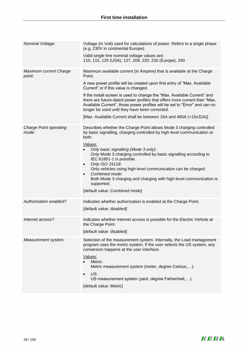
Nominal Voltage:
Voltage (in Volt) used for calculations of power. Refers to a single phase (e.g. 230V in continental Europe).
Valid single line nominal voltage values are: 110, 115, 120 (USA), 127, 208, 220, 230 (Europe), 240
Maximum current Charge point:
Maximum available current (in Ampere) that is available at the Charge Point.
A new power profile will be created upon first entry of “Max. Available Current” or if this value is changed.
If the install screen is used to change the “Max. Available Current” and there are future-dated power profiles that offers more current than “Max. Available Current”, those power profiles will be set to "Error" and can no longer be used until they have been corrected.
[Max. Available Current shall be between 16A and 480A (=15x32A)]
Charge Point operating mode:
Describes whether the Charge Point allows Mode 3 charging controlled by basic signalling, charging controlled by high-level communication or both.
Values:
Only basic signalling (Mode 3 only): Only Mode 3 charging controlled by basic signalling according to IEC 61851-1 is possible.
Only ISO 15118: Only vehicles using high-level communication can be charged.
Combined mode: Both Mode 3 charging and charging with high-level communication is supported.
[default value: Combined mode]
Authorization enabled?
Indicates whether authorization is enabled at the Charge Point.
[default value: disabled]
Internet access?
Indicates whether internet access is possible for the Electric Vehicle at the Charge Point.
[default value: disabled]
Measurement system:
Selection of the measurement system. Internally, the Load management program uses the metric system. If the user selects the US system, any conversion happens at the user interface.
Values:
Metric: Metric measurement system (meter, degree Celsius,…).
US: US measurement system (yard, degree Fahrenheit,…).
[default value: Metric]

First time installation
29 / 156
Time zone:
Selection of the Time zone. Internally, the Load management program uses UTC. If the user selects a different time zone, conversions happen at the user interface.
Language:
Selection of the user interface language. If there is only one user inter-face language available, the parameter "Language" is not shown.
[default value: English]
Buttons
Save: Press the [Save] button to save the installation data.
5.2 Making a backup of the Compact Flash card
After finishing the configuration of the system as described in the following chapters, it is recom-mended to make a backup of the Compact Flash (CF) card, to be able to restore the original sys-tem parameters.
► Turn off the KeContact M10. Navigate through the MMI and select “Shutdown system” (for details see “KeContact M10 MMI menu”.
► Remove the CF card from the KeContact M10 and insert it into a CF card reader.
► Use a suitable program to create an ISO image of the CF card. It is not sufficient to copy the files using the “Copy & Paste” function.

Load management program
30 / 156
6 Load management program
The following screen illustrates the design of the graphical user interface (GUI).
The web page consists of the following components:
A header area at the top of the screen. The header contains the KEBA logo, the product name (KeContact M10) and a tag that identifies the page group to which the current page belongs.
A menu area at the left side of the screen. The menu contains buttons that access the primary screens of the page group to which the current screen belongs. Any screen of the page group includes buttons navigating to all primary screens belong-ing to the screens inside the page groups. There might be secondary screens that are accessed from the primary screens. They will only be shown at the menu if they are visible and/or accessible.
A content area showing the information, entry fields and buttons necessary for the user.
A toolbar showing navigation icons.

Load management program
31 / 156
6.1 Toolbar icons
Help Navigates to the “Help” screen for the current page.
Reboot Reboots the KeContact M10. A reboot of the KeContact M10 will also lead to a loss of con-nection between KeContact M10 and Wallbox and thus to a reboot of the Wallboxes.
About / Information Navigates to the “About” screen.
Monitoring Navigates to the “Top monitoring” screen (identical to charge point monitoring).
Configuration Navigates to the “Top configuration” screen (identical to charge point configuration).
Installation Navigates to the “Installation” screen.
Management Navigates to the “Management menu” screen.
Service Navigates to the “Service menu” screen (identical to software/firmware version overview).
Home Navigates to the “Home” screen.
Back (previous page) Navigates to the previous tab screen (if at the first screen, nothing happens).
Next (next page) Navigates to the next tab screen (if at the last screen, nothing happens).
Logout Log out and return to the “Home” screen.
Refresh Refreshes the current screen (only to be used in status screens).

Load management program
32 / 156
6.2 Accessing the Load management program
► You can easily access the Load management program using a conventional web browser (e.g. Internet Explorer). Please ask your network administrator for the detailed integration of the KeContact M10 in your corporate network. This is not part of this manual.
Connection via port ETH0 (for Installation):
Type in the IP address http://192.168.25.1:9091/admin of the KeContact M10 in the ad-
dress bar of your web browser (an open port “9091” is required to get access to the application).
Secured connection via port ETH1:
Type in the IP address https://xxx.xxx.xxx.xxx:8443/admin of the KeContact M10 in the
address bar of your web browser (an open port “8443” is required to get access to the applica-tion). After a restart of the KeContact M10, the IP address is shown in the MMI display. Please note that higher versions of the Internet Explorer 9 do not accept certificates which are unsafe (like the KEBA standard certificate). Certificates: To guarantee a safe connection via HTTPS, the KeContact M10 is delivered with a digital KEBA standard certificate. The standard certificate is valid for at least 2 years. KEBA standard certificates are non registered and unsafe certificates. This is the reason why web browsers may show a warning note when the M10 User Interface is loaded. It is strongly recommended to replace the pre-installed, unsafe KEBA standard certificate with a trusted certificate of your choice. The certificates can be replaced via the M10 User Interface.
► The HOME screen of the Load management program appears.
Without Login you have access to the HOME screen and the Monitoring screens. If you want to change con-figuration values, a Login with Username and Password is required. Accounts and their access rights and passwords can be maintained at the account management screens of the KeContact M10. Access rights refer to the groups of screens such as installation, configuration or man-agement accessible from the toolbar at the bottom of a KeContact M10 screen. In addition, there is a special access right for the account management screen belonging to the management group. The user can change its password from the password entry screen. The KeContact M10 ships with predefined accounts supporting typical user roles such as an installer. It is strongly recommended to change the passwords of those accounts during the initial configuration of the Ke-Contact M10.

Load management program
33 / 156
6.2.1 Login
Some functions of the Load management program may require a Login with Username and Password.
Login screen
Buttons
Login: Enter “User name” and “Password” and press the [Login] button to ac-cess the KeContact Load management program.
If the user doesn't work with one of the password protected screens for 15 minutes, it will be automatically logged out.
Change Password: Press the [Change Password] button to go to the change password screens.
Typical workflow: Using password protected screens The user wants to enter a password-protected area, but is not logged in or is logged in with an account that doesn’t have the right to access the area. The user selects a screen in the password-protected area typically by pressing a button in the toolbar at the bottom of the screen.
► The KeContact M10 presents the login screen. Enter Username and Password and press the [Login] button. The screen selected will be shown.
► Please press the [Logout] button in the toolbar after performing the work in the password protected area. The HOME screen appears.

Load management program
34 / 156
6.2.2 Change password
Change password screen
Parameters
User name: User for which the password shall be changed.
Current password: Enter your current case sensitive password for the account.
New password: Enter your new case sensitive password for the account.
Repeat new password: Repeat the (case sensitive) password for the account. The two “New password” fields must be equal in order to be accepted.
Buttons
Change Password: Press the [Change Password] button to save the new password.

Load management program
35 / 156
Typical workflow: Change password
► Try to access a password-protected screen. The KeContact M10 presents the login screen.
► Press the button [Change Password]. The “Change Password” screen appears.
► Enter the old and the new password and press the button [Change Password].
In case a user forgets the password, an administrator can set a new password.
6.2.3 Standard accounts and passwords
Administrator-Account Deleting the Administrator-Account is not possible. Change the password for this account immediately at the first start-up! Do not use very simple or predictable passwords (do not use e.g. “User name: admin / Pass-word: password”).
User name: admin
Password: Serial number of the M10 Note: The serial number is shown at the login screen (ID = “Keba_CS”serial number”)
Installation-Account The installation account has access to all free accessible screens and the installation menu. Only accessible with a direct physical connection to the Ethernet port [Eth0] of the KeContact M10.
User name: installer
Password: kecontactm10 Configuration-Account (Management-Account) With the Configuration-Account the system is operated. It has access to all menus except the „Installation menu“. It is highly recommended to change at least the password for this account.
User name: manager
Password: danube User-Accounts Depending on the system it is possible to create user accounts with specific access permissions (details see chapter “Management menu -> Manage Accounts”).
In your own interest, ensure to store all changed passwords (e.g., employee passwords) at a safe place. If necessary, this allows the system owner to restore access to the accounts.

Load management program
36 / 156
6.3 Home screen
The “Home” screen shows the global status of all connected Wallboxes and is accessible without Login. The screen will refresh automatically if any states change. The number of the Wallbox is shown at the icon. The number of the Wallbox is defined by the DIP switch settings inside the Wallbox. To be able to identify a Wallbox the Wallbox number is also shown on a label that should be affixed to the Wallbox during the installation. During normal operation, the “Home” screen is the only monitoring screen that needs to be used. From this screen, it is possible to show details about the Charge Point and the individual Wallboxes.
Home screen
► Click on a Wallbox icon to navigate to the “Monitoring menu” of the selected Wallbox.

Load management program
37 / 156
Description of the “Home screen” icons
Wallbox free (green) The Wallbox is working, no vehicle is plugged in.
Wallbox occupied (grey) A vehicle is plugged into the Wallbox. The vehicle might charge, might be in a charging pause or might be fully charged.
Wallbox degraded (red) The Wallbox is working, but has only a limited functionality. Currently, there are two reasons for the Wallbox to be in this state: - Communication for ISO 15118 doesn't work, but ISO 15118 is enabled in the Wallbox. - The temperature monitoring has recognized a temperature that is too high and has reduced the power that can be consumed by the electric vehicle.
Wallbox unavailable (grey) The Wallbox doesn't work, no electric vehicle might charge. This might be due to a Wallbox malfunction or a problem in the communication between the Wallbox and the KeContact M10 has occured.
6.4 Rebooting the system (Login required)
If there are problems that cannot be properly diagnosed remotely, it might be helpful to reboot the system. Reboots are often tried to get out of an error situation when there is not enough time to analyze the root cause. The KeContact M10 resumes the Charging Sessions after a restart.
► Navigate to the “Management menu” by clicking at the [Management] icon in the toolbar at the bottom of the screen.
Reboot the system by pressing the [Reboot] icon in the toolbar at the bottom of the screen. This reboots both the KeContact M10 and the connected Wallboxes.
The reboot process will take several minutes. After the reboot process has been completed, the user inter-face of the KeContact M10 is accessible again.

Load management program
38 / 156
6.5 Monitoring menu
Press the [Monitoring] button.
Monitoring is the process of supervising the day-to-day operation of the Charge Point.
Monitoring menu – Charge Point overview
The most important work flows in monitoring are:
Monitoring the Charge Point: Day-to-day supervision of the Charge Point using the Home screen.
Viewing Charge Point details: If something extraordinary happens or a driver calls, it might be neces-sary to view details about the charge point.
Viewing Wallbox details: If something extraordinary happens or a driver calls, it might be necessary to view details about the Charge Point.

Load management program
39 / 156
6.5.1 Charge Point Overview
This screen shows details about the Charge Point and its parameters including aggregated status data cov-ering all Wallboxes. The screen doesn't automatically refresh. Refresh the screen by clicking the refresh button at the toolbar.
6.5.1.1 General tab
Charge Point overview – General
Charge Point information
ID: Unique ID of the Charge Point. In ISO 15118-2, the ID of the Charge Point is called EVSE-ID. According to ISO 15118-2, it is a globally unique identifier containing an octet string. In communication with the Electric Vehicle, the Charge Point ID will be concatenated with the Socket ID to receive the EVSE-ID. [default value: Charge Point ID]
Name:
Human-readable name of the Charge Point for presentation purposes. [default value: Charge Point ID]

Load management program
40 / 156
Status: Status of the Charge Point.
Display values:
Available: Everything is functional and at least one Socket is not occupied and/or unavailable.
Occupied: All Sockets are used and/or unavailable.
Degraded: There is a failure on any of the Charge Point devices or Sockets.
Faulted: The Charge Point (and not only a Socket) has a fatal error.
Unavailable: The Charge Point is not available for operation.
Model: Model name of the Charge Point.
Display values:
KeContact M10
Vendor: Vendor name of the Charge Point.
General information
Charge Point operating mode:
Describes whether the Charge Point allows Mode 3 charging controlled by basic signalling, charging controlled by high-level communication or both.
Maximum current Charge Point:
Maximum available current (in Ampere) that is available at the Charge Point.
Nominal voltage: Voltage (in Volt) used for calculations of power. Refers to a single phase (e.g. 230V in continental Europe).
Authorization enabled?
Indicates whether authorization is enabled at the Charge Point.
Internet access?
Indicates whether internet access is possible for the Electric Vehicle at the Charge Point which is using high-level communication ISO 15118.
User interface
Measurement system:
Shows the selected measurement system (Metric system, US measure-ment system).
Time zone:
Shows the selected Time zone (GMT).
Language: Shows the selected user interface language.

Load management program
41 / 156
Typical workflow: Viewing Charge Point details
► Press the Monitoring button in the toolbar. The Charge Point Monitoring screen appears.
► If the general information is not sufficient, more details can be seen at other tabs of the screen. They can be reached by pressing [>] or [<] at the toolbar or by clicking at the tab headers shown at the content area of the screen.
The following information can be viewed and analyzed in addition to general information. Most of this information might be of interest for troubleshooting. Load Management: Configuration options for load management (distribution of available energy to all vehicles that have been plugged into Wallboxes belonging to the Charge Point). Authorization: Configuration options for the way users will be authorized. Metering and Power Control: Configuration options for the process of controlling whether the electric vehicle doesn't use more than the assigned power and for the way metering data will be collected. Power Profile: The currently active power profile determining limits of the available power over time. Session overview: This screen provides an overview of Charging Sessions that are ongoing or have been finished. By selecting a Charging Session and pressing the "Session History" button, the session history screen is shown for that particular session. Session history: A charging session starts, when an electric vehicle plugs in and stops when the electric vehicle will be disconnected. During a Charging Session, there will be multiple charging transactions. This screen provides an overview about the events that occurred during the processing of a Charging Transaction. Power Usage: This screen shows how much energy has been consumed today or during a particular day in the past.
► Because most data shown at the screens are static, the screens will not be refreshed.
Up to date information can be loaded by clicking on the Refresh button .
► Return to the home screen by clicking on the [HOME] button .

Load management program
42 / 156
6.5.1.2 Load Management tab
Charge Point overview – Load Management
Charge Point information
ID: Unique ID of the Charge Point. In ISO 15118-2, the ID of the Charge Point is called EVSE-ID. According to ISO 15118-2, it is a globally unique identifier containing an octet string. In communication with the Electric Vehicle, the Charge Point ID will be concatenated with the Socket ID to receive the EVSE-ID.
[default value: Charge Point ID]
Name:
Human-readable name of the Charge Point for presentation purposes.
[default value: Charge Point ID]

Load management program
43 / 156
Charging strategy parameters
Charging strategy category:
Category of the charging strategy. Characterises the rules that will be used by the Charging Strategy. Two Charging Strategies with the same Charging Strategy Category might have different parameters.
Display values:
Fifo for fleets: Strategy for corporate fleets of EVs based on the “First come, First serve” principle.
Minimum current Low-level (PWM):
The minimum current (in Ampere) that will be used during charging of Electric Vehicles controlled by basic signalling. The default is the limitation defined in IEC 61851-1. Since some Electric Vehicles require a higher minimum current, it is possible to set that amount to a higher level. Please also see: www.kecontact.com/vehicle-specifics.html for further information and configuration guidelines.
Maximum charging pause:
Maximum duration of a charging pause initiated by the Charge Point (in seconds) before the Charge Point tries to wake up the Electric Vehicle. An Electrical Vehicle was put into sleep mode, because the available power at the Charge Point was less than the minimum current low-level for that Wallbox.
Reserve previous profile? [only ISO 15118 relevant]
Indicates whether the energy agreed in a previously agreed Charging Profile will be reserved during the renegotiation of a Charging Profile.
Display values:
No: The energy will be never reserved.
EV initiated only: Energy is reserved if the renegotiation is initiated by the Electric Ve-hicle.
Always: The energy will always be reserved during the renegotiation.
Energy pricing
Unit of energy pricing: The unit of energy (such as kWh) for which a price is defined in the Pow-er Profile.
Display values:
Wh, kWh
Currency:
The currency used at the Charge Point for pricing energy. Alphabetic code from ISO4217 (optional). Energy prices can be used to indicate preferences for times of energy delivery if no currency is given.

Load management program
44 / 156
6.5.1.3 Authorization tab
Charge Point overview – Authorization
Charge Point information
ID: Unique ID of the Charge Point. In ISO 15118-2, the ID of the Charge Point is called EVSE-ID. According to ISO 15118-2, it is a globally unique identifier containing an octet string. In communication with the Electric Vehicle, the Charge Point ID will be concatenated with the Socket ID to receive the EVSE-ID.
[default value: Charge Point ID]
Name:
Human-readable name of the Charge Point for presentation purposes.
[default value: Charge Point ID]

Load management program
45 / 156
Authorization [only ISO 15118 relevant]*
Authorization enabled?
Indicates whether authorization is enabled at the Charge Point.
Learns charging token?
Indicates whether a Charging Token can be generated, if an Electric Ve-hicle plugs into a Socket with enabled Authorization.
Note. A creation of Charging Tokens will only be done for some types of Charging Tokens such as PEV-IDs.
Automatically accepts token?
Indicates whether a Charging Token is generated by plugging in an Elec-tric Vehicle into a Socket with enabled Authorization.
Automatic acceptance dura-tion:
Default value for the number of days until the expiration of a Charging Token that will be automatically created.
Default expiry period:
Default value for the number of days a Charging Token will be considered accepted if no expiration date is delivered to the Charge Point when au-thenticating the Charging Token.
(*) This options are only active if “Authorization enabled?” = “Yes”.
Power line communication
Uses public NMK? [only ISO 15118 relevant]
Indicates whether the Charge Point uses the public NMK or the private NMK for the communication with the Wallboxes.
Please note: If authorization is enabled and the Charge Point is operating in combined mode, an Electric Vehicle which is charging with basic signalling will charge 30 seconds until charging will be stopped if no authorization has been done. Within the 30 seconds, a possible high-level communication can be established.

Load management program
46 / 156
6.5.1.4 Metering and Power control tab
Charge Point overview – Metering and Power control
Charge Point information
ID: Unique ID of the Charge Point. In ISO 15118-2, the ID of the Charge Point is called EVSE-ID. According to ISO 15118-2, it is a globally unique identifier containing an octet string. In communication with the Electric Vehicle, the Charge Point ID will be concatenated with the Socket ID to receive the EVSE-ID.
[default value: Charge Point ID]
Name:
Human-readable name of the Charge Point for presentation purposes.
[default value: Charge Point ID]

Load management program
47 / 156
Metering
Publishes meter values:
Decides how intermediate meter reading will be handled.
Display values:
No: Intermediate meter readings will neither be stored in the Charging Transaction nor written to a log file.
Most recent: The most recent intermediate meter reading will be stored at the Charging Transaction, but no log file entry will be written.
Full log: The most recent intermediate meter reading will be stored at the Charging Transaction and written to the log file.
Metering period:
Duration in seconds between two consecutive intermediate meter read-ings.
Meter collection type:
Type of collection of meter readings for export.
Display values:
ClockAligned: Meter readings will be generated for Sockets or the Charge Point. They will be collected in evenly spaced intervals starting from mid-night.
Sampled: Meter readings will be generated for Charging sessions. They will be collected at the start and end of the Charging session as well as in evenly spaced intervals starting from the start of the Charging ses-sion.
Both: Both clock-aligned and sampled Meter readings will be collected.
Collection interval clock aligned:
Size (in seconds) of the clock-aligned data interval. This is the size of the set of evenly spaced aggregation intervals per day, starting at 00:00:00 (midnight).
Collection interval session aligned:
Interval (in seconds) between sampling of metering data, intended to be exported. Sampling starts at the begin of the Charging session.

Load management program
48 / 156
Power control
Power control action:
Defines, whether the Charge Point controls the level of power drawn by the Electric Vehicle.
Display values:
No action The Charge Point does not control the power levels drawn by the Electric Vehicles connected to the Wallbox.
Only logging The Charge Point logs, if an Electric Vehicle exceeds the assigned power levels.
When outside global limits The Charge Point disconnects an Electric Vehicle exceeding its as-signed power levels, if the power used by all Electric Vehicles ex-ceeds the power made available to the Charge Point.
Always The Charge Point disconnects an Electric Vehicle if it exceeds the assigned power levels.
Tolerance power control:
Level of current (in Ampere) by which the power must exceed the as-signed power level before the power control takes action.
Max excess count ISO 15118:
Maximum number of measurements at which the assigned power level must be exceeded during charging control using high-level communica-tion, before power control takes action.
Max excess count low-level:
Maximum number of measurements at which the assigned power level must be exceeded during Mode 3 charging, before power control takes action.
History repeated violations:
Indicates if multiple session history entries will be written if an Electric Vehicle exceeds the assigned power level multiple times or if a session history entry will only be written the first time.

Load management program
49 / 156
6.5.1.5 Power profile tab
Charge Point overview – Power profile
Charge Point information
ID: Unique ID of the Charge Point. In ISO 15118-2, the ID of the Charge Point is called EVSE-ID. According to ISO 15118-2, it is a globally unique identifier containing an octet string. In communication with the Electric Vehicle, the Charge Point ID will be concatenated with the Socket ID to receive the EVSE-ID.
[default value: Charge Point ID]
Name:
Human-readable name of the Charge Point for presentation purposes.
[default value: Charge Point ID]

Load management program
50 / 156
Power profile
Valid from:
Point in time at which the validity of a Power Profile begins. A Power Pro-file remains valid until its successor gets valid.
[DD.MM.YYYY]
Special day:
Special day(s) at which the Power Profile overrides the currently active Power Profile.
Reserved for ISO 15118: [Only in combined mode ac-tive]
Percentage of the Maximum Current Offered that is reserved for Electric Vehicles using high-level communication.
[Maximum is 100%]
100% means that the complete available power of the M10 is reserved for ISO 15118 vehicles, even if Mode 3 vehicles want to charge.
Power profile items
Item name:
Name of the Power Profile.
Days of week:
Days of the week at which the Power Profile is valid. (Monday, Tuesday, Wednesday,….)
From / To:
Time period from / to the Power Profile is valid.
Max. Current [A]:
Maximum current for this Power Profile.
Price:
Energy price during this Power Profile.
Current 15118 [A]:
Current (in Ampere) that is reserved for charging by vehicles using high-level communication.
Optional: If no value is set, the value will be calculated as follows: “Reserved for ISO 15118” x “Max current” / 100

Load management program
51 / 156
6.5.2 Wallbox details
This screen shows details about one Wallbox and can be called for a particular Wallbox (Wallbox Number) by clicking on one of the Wallbox icons at the Home screen. The screen doesn't automatically refresh. Re-fresh the screen by clicking the refresh button at the toolbar.
6.5.2.1 Charging Overview tab
Wallbox details – Charging overview
Charging Session
Wallbox Number: The drop down box shows the socket number of all Wallboxes that are visible at the home screen.
If the user changes the Wallbox number, the screen is shown for the Wallbox selected by the user. If no Wallbox is passed to the screen, Wallbox 1 will be selected.
Session ID: Unique identifier of the Charging Session. Unique within the scope of a Charge Point. The Session Sequence ID is generated by the Charge Point during the session setup.

Load management program
52 / 156
Session state: Shows the state of the current Charging Session.
Display values:
Not plugged in: No electric vehicle is connected to the Wallbox.
Standby: The vehicle is connected, but on standby.
Charging: The vehicle is charging or in a charging pause and the vehicle is not blocked.
Blocked: The vehicle has been blocked by the Wallbox or no active charging transaction exists.
Error: The socket is degraded or fatal.
Session start time: Point in time when the Charging Session has started.
Departure Time: Planned end of charging as communicated by the Electric Vehicle during charge parameter discovery.
Charging State details
Signalling: Describes whether the Charging Session is a Mode 3 charging session or a high-level charging session.
Display values:
Basic signalling: Mode 3 charging according to IEC 61851-1 controlled by basic signal-ling.
ISO 15118: Charging session controlled by high-level communication.
Number of phases: The maximum number of phases which a Electric Vehicle can use during the charging transaction. Must be 1 or 3.
Current offered: Current offered at the Wallbox (taken from charging profile or the preas-signed current, whichever applies).
Current measured: Current according to the last measurement at the Wallbox.
Charging State details
Energy Requested: Energy requested by the electric vehicle during the last charge parameter negotiation. Empty for charging controlled by basic signalling.
Energy Consumed: Energy consumed during the Charging Session.
Wallbox state: Shows the state of the selected Wallbox.
Display values:
Free: No vehicle is connected.
Not ready to charge: The Wallbox is operational and the power switch is open.
Offering energy:

Load management program
53 / 156
The Wallbox is operational and the power switch is closed.
Degraded: Some Wallbox functions are not working (e.g. the Wallbox is derated because of high temperature).
Offline: The Wallbox is not working at all.
Vehicle state: Shows the state of the vehicle connected to the selected Wallbox.
Display values:
No Vehicle: No vehicle is connected to the Wallbox.
Plugged In: A vehicle is plugged in.
Ready to charge: The vehicle is ready to consume energy.
Charging: There is an active charging session, the Wallbox is operational and the vehicle is not blocked.
Error code: Decimal error code reported by the Wallbox in case the Wallbox is in an error state.
Typical workflow: Viewing Wallbox details
► Press the icon representing the Wallbox at the home screen. The Wallbox monitoring screen belonging to the Wallbox appears.
► If the general information is not sufficient, more details can be seen at other tabs of the screen. They can be reached by pressing [>] or [<] at the toolbar or by clicking at the tab headers shown at the content area of the screen.
► The following information can be viewed and analyzed in addition to the general information. Most of this information might be of interest when troubleshooting. Wallbox settings: Details about the settings of the Wallbox. This includes settings entered at the DIP switches of the Wallbox and information stored inside the wallbox. Wallbox operation: Details about the current operation of the Wallbox. Vehicle overview: Details about the vehicle attached to the wallbox (mostly only available for electric vehicles using ISO 15118).
► Because most data shown at the screens are static, the screens will not be refreshed.
Up to date information can be loaded by clicking on the [Refresh] button .
► Return to the home screen by clicking on the [HOME] button .

Load management program
54 / 156
6.5.2.2 Wallbox Settings tab
Wallbox details – Wallbox settings
Identification
Wallbox Number: The drop down box shows the socket number of all Wallboxes that are visible at the home screen.
If the user changes the Wallbox number, the screen is shown for the Wallbox selected by the user. If no Wallbox is passed to the screen, Wallbox 1 will be selected.
Model name Wallbox: Model name of the Wallbox.
Display values:
KeContact P20
Wallbox serial number: Serial number stored in the EPROM of the Wallbox.
EVSE-ID for ISO 15118: ID of the Wallbox to be used when communicating with the Electric Vehi-cle. The Charge Point ID will be concatenated with the Socket ID to re-ceive the EVSE-ID.

Load management program
55 / 156
Details
Firmware version Version of the firmware deployed at the Wallbox.
Maximum available current: Maximum energy level available by charging at the Wallbox (in Ampere).
Number of phases: Number of phases supported by the Wallbox (must be 1 or 3).
Phase used: The phase to which the socket is connected for single-phase charging.
Display values:
L1, L2, L3.
Fixed cable? Wallbox with fixed cable:
Display values:
Yes / No.
IP address (Wallbox):
IP address of the Wallbox.
Values: 192.168.25.xxx (where xxx is the Socket ID)
Ventilation supported? Indicates whether ventilation is supported.
Display values:
Yes / No.
Requires authorization? Indicates whether authorization is enabled at the Wallbox.
Display values:
Yes / No.

Load management program
56 / 156
6.5.2.3 Wallbox Operation tab
Wallbox details – Wallbox operation
Identification
Wallbox Number: The drop down box shows the socket number of all Wallboxes that are visible at the home screen.
If the user changes the Wallbox number, the screen is shown for the Wallbox selected by the user. If no Wallbox is passed to the screen, Wallbox 1 will be selected.
EVSE-ID for ISO 15118: ID of the Wallbox to be used when communicating with the Electric Vehi-cle. The Charge Point ID will be concatenated with the Socket ID to re-ceive the EVSE-ID.
Wallbox operating mode: Describes whether the Wallbox allows Mode 3 charging controlled by basic signalling, charging controlled by high-level communication or both.
Values:
Only basic signalling (Mode 3 only): Only Mode 3 charging controlled by basic signalling according to IEC 61851-1 is possible.
Only ISO 15118: Only vehicles using high-level communication can be charged.
Combined mode: Both Mode 3 charging and charging with high-level communication is supported.

Load management program
57 / 156
Wallbox available? Indicates whether the Wallbox is available for charging.
Wallbox reserved? Indicates whether the Wallbox has been reserved for a particular charg-ing token.
Details
Fixed cable? Indicates if the Wallbox has a fixed cable or works with an external cable that will be plugged into the Wallbox.
Display values:
Yes / No.
Wallbox plugged? Indicates whether a cable or a vehicle is plugged into the Wallbox.
Display values:
Vehicle and Wallbox
Wallbox only
No
Wallbox connector locked? Indicates whether the connector at the side of Wallbox is locked. If there is a fatal error (Socket Status = fatal), the value of this attribute might not be accurate, but only indicate the last status reported by the Wallbox. A Wallbox with a fixed cable will always report locked.
Display values:
Yes / No.
Wallbox pulsing? Indicates whether the Wallbox is pulsing.
Display values:
Yes / No.
Power switch closed? Indicates whether the power switch inside the Wallbox is closed. If there is a fatal error (Socket Status=fatal), the value of this attribute might not be accurate, but only indicate the last status reported by the Wallbox.
Display values:
Yes / No.
Nominal voltage: Voltage (in Volt) used for calculations of power which will be assigned to the Wallboxes in case of load management. Refers to a single phase (e.g. 230V in continental Europe).
Valid single line nominal voltage values are: 110, 115, 120 (USA), 127, 208, 220, 230 (Europe), 240
Voltage measured: Voltage measured at the most recent measurement.
Current offered? Current offered at the Wallbox (taken from charging profile or the preas-signed current, whichever applies).
Housing inside temperature? Shows the temperature inside the Wallbox.
Display values:
°C / °F.
Energy meter: Energy meter value in [kWh].

Load management program
58 / 156
6.5.2.4 Vehicle Overview tab
Wallbox details – Vehicle overview
Identification
Wallbox Number: The drop down box shows the socket number of all Wallboxes that are visible at the home screen.
If the user changes the Wallbox number, the screen is shown for the Wallbox selected by the user. If no Wallbox is passed to the screen, Wallbox 1 will be selected.
Vehicle ID: [only ISO 15118 relevant]
Specifies the identification of the electric vehicle in a readable format. Optional attribute, can only be present with high-level communication. In ISO 15118-2 it is called PEV-ID. If present, the PEV-ID contains the MAC address of the EV as a string.
Contract ID: [only ISO 15118 relevant]
Contains the unique contract identification number. Identifies the contract, on the electric vehicle. Several electric vehicles might use the same con-tract ID. Only for electric vehicles using high-level communication.

Load management program
59 / 156
Vehicle details
Signalling: Describes whether the Charging Session is a Mode 3 charging session or a high-level charging session.
Display values:
Basic signalling: Mode 3 charging according to IEC 61851-1 controlled by basic signal-ling.
ISO 15118: Charging session controlled by high-level communication.
Time plugged in: Point in time when the charging session has started.
Departure time: [only ISO 15118 relevant]
Planned end of charging as communicated by the electric vehicle during charge parameter discovery.
Energy consumed: Energy consumed during the Charging session.
Time started: Point in time when the charging transaction has started.
Electric vehicles can only charge in charging transactions. A charging transaction is terminated by a renegotiation, a charging pause, a power cut or several other exceptions.
Time finished: Point in time when the charging transaction has ended.
Termination reason: Code indicating the reason for the termination of a transaction.
Display values:
Vehicle unplugged: The EV has initiated the termination by unplugging.
ISO 15118 command: The EV has initiated the termination by unplugging. High-level: The EV has initiated the termination by sending a com-mand via high-level communication.
Socket failure: The charging transaction has been terminated by the Wallbox be-cause of a socket failure (for example overheating).
Power control: The charging transaction has been terminated because the EV has drawn more than the assigned power.
Housekeeping: The EV has unplugged during a power cut, socket unavailability or down-time of the KeContact M10.
Charging profile exceeded: The EV has exceeded its charging profile.
Derating The charging transaction has been terminated because the socket has been derated.

Load management program
60 / 156
6.5.3 Session overview
This screen is listing all Charging Sessions (both active and historical).
Monitoring menu – Session overview
Charge Point information
ID: Unique ID of the Charge Point. In ISO 15118-2, the ID of the Charge Point is called EVSE-ID. According to ISO 15118-2, it is a globally unique identifier containing an octet string. In communication with the Electric Vehicle, the Charge Point ID will be concatenated with the Socket ID to receive the EVSE-ID.
[default value: Charge Point ID]
Name:
Human-readable name of the Charge Point for presentation purposes.
[default value: Charge Point ID]

Load management program
61 / 156
Sessions table
Session ID: Unique identifier of the Charging Session.
Wallbox: Socket number of the Wallbox.
Start: Point in time when the charging transaction has started.
End: Point in time when the charging transaction has ended.
Signalling: Shows whether the Charging Session was a “Low-level (PWM)” charging session or a “High-level (ISO 15118)” charging session.
Termination: Code indicating the reason for the termination of a transaction.
Display values:
Vehicle unplugged: The EV has initiated the termination by unplugging.
ISO 15118 command: The EV has initiated the termination by unplugging. High-level: The EV has initiated the termination by sending a com-mand via high-level communication.
Socket failure: The charging transaction has been terminated by the Charge Point because of a socket failure (for example overheating).
Power control: The charging transaction has been terminated because the EV has drawn more than the assigned power.
Authorization failure: Authorization has been denied for the charging session.
Housekeeping. The EV has unplugged during a power cut, socket unavailability or down-time of the KeContact M10.
Energy consumed [kWh]: Energy consumed during the Charging Session.
Current [A]: Current according to the last measurement at the Wallbox.
Buttons
Got to Wallbox: Press the [Go to Wallbox] button to go to the Monitoring menu of the se-lected Wallbox.
Session history: Press the [Session history] button to go to the Session History screen.

Load management program
62 / 156
Typical workflow: Monitor Charging Sessions
► Press the Monitoring button in the toolbar. The Charge Point Monitoring screen appears.
► Press the menu button [Session Overview] at the left side of the screen. The session overview screen appears. This screen provides an overview of charging sessions that are ongoing or have been finished. By selecting a charging session and pressing the [Session History] button, the session history screen is shown for that particular session. By selecting a charging session and pressing the [Go to Wallbox] button, the Wallbox monitoring screen is shown for the Wallbox at which the session occurs.
► The session history provides a log of important events that have occurred during the charging session and it’s charging transactions. For an active charging sessions, further details can be found at the monitoring screens for the Wallbox.
► Because most data shown at the screens are static, the screens will not be refreshed.
Up to date information can be loaded by clicking on the [Refresh] button .
► Return to the home screen by clicking on the [HOME] button .

Load management program
63 / 156
6.5.4 Session history
This screen shows the charging transactions of a particular charging session. To access the session history of a charging session, mark a charging session and press the “Session Histo-ry” button at the right bottom end of the screen.
Monitoring menu – Session history

Load management program
64 / 156
Session
Session ID: Unique identifier of the Charging Session.
Wallbox number: Socket number of the Wallbox.
Session start time: Point in time when the Charging Session has started.
Session end time: Point in time when the Charging Session has ended.
Session history table
History type:
The most important types of history entries.
Display values:
Start session A Charging Session has started.
Resume session A charging session has been resumed by the Electric Vehicle.
End session A Charging Session has ended.
Start transaction A Charging Transaction has started.
Waiting authorization The Wallbox waits for authorization.
End transaction A Charging Transaction has ended.
Power exceeded The Electric Vehicle has drawn more power than assigned in the Charging Profile.
No ventilation The Electric Vehicle has requested ventilation, but the socket doesn't support ventilation.
Time:
Timestamp of the entry into the session history.
Meter reading:
Meter reading in the transaction history. Might be different from attributes depending on the type of transaction.
Termination:
Termination reason at the session history. Might be either “Termination Reasons Session” or “Termination Reason Transaction” depending on the type of history entry.
Details:
Detailed information contained in the session history.
It will be populated with additional information such as "Contract ID" for the start of a session or the measured current in case of exceeding the assigned current.

Load management program
65 / 156
6.5.5 Power usage
This screen shows the power usage during a time interval.
Monitoring menu – Power Usage
Please select a day
Day: Please select a day. If the user doesn't enter a day, today will be as-sumed. For the entry of the day, a date picker widget will be used.
Power Usage table
From: Point in time at which the interval in the power usage table starts for the selected day.
Cars at start: Number of cars that where plugged in during the time interval.
Cars arrived: Number of cars that arrived during the time interval.
Cars left: Number of cars that left during the time interval.
Cars at peak: Maximum number of cars that were plugged in during the time interval.
Energy consumed:
Overall energy consumed during the time interval (by all vehicles).
Energy consumed will be measured as follows: For all Wallboxes, the difference between the last meter reading of the previous period and the last meter reading of the current period will be calculated. The sum for all Wallboxes will be calculated to get the overall energy.

Load management program
66 / 156
6.6 Configuration menu
Press the [Configuration] button to show the “Configuration menu”.
Configuration screens for the Charge Point (global parameters).
Configuration menu – Charge Point configuration
Additional information: Operating mode Cables connecting an electric vehicle with a KeContact P20 Wallbox contain 3 or 5 wires for the transport of electric energy and two wires for data communication. There are two protocols (set of rules for communica-tion) for data exchange between the electric vehicle and the Charge Point - Basic Signalling (according to IEC 61851-1) and ISO/IEC 15118 (in short ISO 15118).
Those two protocols are not mutually exclusive, ISO 15118 works on top of Basic Signalling. ISO 15118 is better suited to optimize the power delivery capacity of the electricity grid and can handle authorization. As of today, most electric vehicles only support basic signalling.

Load management program
67 / 156
A Charge Point and the connected Wallboxes can have three different operating modes:
Only Basic Signalling Only Basic Signalling is supported. Since electric vehicles using ISO 15118 can fall back to Basic Signal-ling, they can charge, but without having the advantages of ISO 15118 communication.
Only ISO 15118 Only electric vehicles supporting ISO 15118 can charge.
Combined Mode Both, Basic Signalling and ISO 15118 is supported. When a car is plugged into a Wallbox, the Charge Point tries to establish an ISO 15118 communication. If this doesn't work, “Basic Signalling” will be used for the communication after 30 seconds.
If the Operating mode of a Charge Point is "Only Basic Signalling" or "Only ISO 15118", all Wallboxes must have the Operating mode "Only Basic Signalling" or "Only ISO 15118" respectively. If the Operating mode of a Charge Point is "Combined mode", Wallboxes can have any Operating mode. The ISO 15118 version used by Daimler's Smart III Electric Drive requires a security key (Network Member-ship Key, NMK) to establish a communication link between the Wallbox and the electric vehicle. The Smart III actually supports two NMKs, a public key for communication for example at a repair shop or for a public Charging Station and a private key that can be stored inside the electric vehicle. A KeContact M10 has to be configured to use either the public or the private NMK. The following workflows are relevant for managing the Operating mode of a Charge Point:
Change the Operating Mode of a Charge Point A KeContact M10 ships with "Combined mode" as the default operating mode. This operating mode can be changed using the web user interface.
Change the Operating Mode of a Wallbox If a wallbox is installed at a Charge Point, its operating mode will be initialized with the operating mode of the Charge Point.
If the operator is not logged into the KeContact M10 or doesn't have the necessary access rights, the Login screen will appear. The Operating mode of the Charge Point can also be configured at the Installation screen.

Load management program
68 / 156
6.6.1 Charge Point configuration
These screens allow the configuration of the Charge Point parameters.
6.6.1.1 General tab
Charge Point configuration– General
Charge Point information
ID: Unique ID of the Charge Point. In ISO 15118-2, the ID of the Charge Point is called EVSE-ID. According to ISO 15118-2, it is a globally unique identifier containing an octet string. In communication with the Electric Vehicle, the Charge Point ID will be concatenated with the Socket ID to receive the EVSE-ID.
[default value: Charge Point ID]
Name:
Human-readable name of the Charge Point for presentation purposes.
[default value: Charge Point ID]
Model: Model name of the Charge Point.
Display values:
KeContact M10

Load management program
69 / 156
General information
Charge Point operating mode:
Describes whether the Charge Point allows Mode 3 charging controlled by basic signalling, charging controlled by high-level communication or both.
Values:
Only basic signalling (Mode 3 only): Only Mode 3 charging controlled by basic signalling according to IEC 61851-1 is possible.
Only ISO 15118: Only vehicles using high-level communication can be charged.
Combined mode: Both Mode 3 charging and charging with high-level communication is supported.
[default value: Combined mode]
Maximum current Charge Point:
Maximum available current (in Ampere) that is available at the Charge Point. Most likely, this is a limitation determined by the power delivery contract of the organization using the M10 system.
A new power profile will be created upon first entry of “Max. Available Current” or if this value is changed by using this screen.
If this screen is used to change the “Max. Available Current” and there are future-dated power profiles that offer more current than “Max. Availa-ble Current”, those power profiles will be set to "Error" and can no longer be used until they have been corrected. The state might change if “Max. Available Current” is increased again or if the power profile is changed.
[Max. Available Current shall be between 16A and 480A (=15x32A)]
Nominal voltage: Voltage (in Volt) used for calculations of power. Refers to a single phase (e.g. 230V in continental Europe).
Valid single line nominal voltage values are: 110, 115, 120 (USA), 127, 208, 220, 230 (Europe), 240
Internet access? [only ISO 15118 relevant]
Indicates whether internet access is possible for the Electric Vehicle at the Charge Point.
[default value: disabled]
User interface
Measurement system:
Selection of the measurement system. Internally, the Load management program uses the metric system. If the user selects the US system, any conversion happens at the user interface.
Values:
Metric: Metric measurement system (meter, degree Celsius,…).
US: US measurement system (yard, degree Fahrenheit,…).
[default value: Metric]
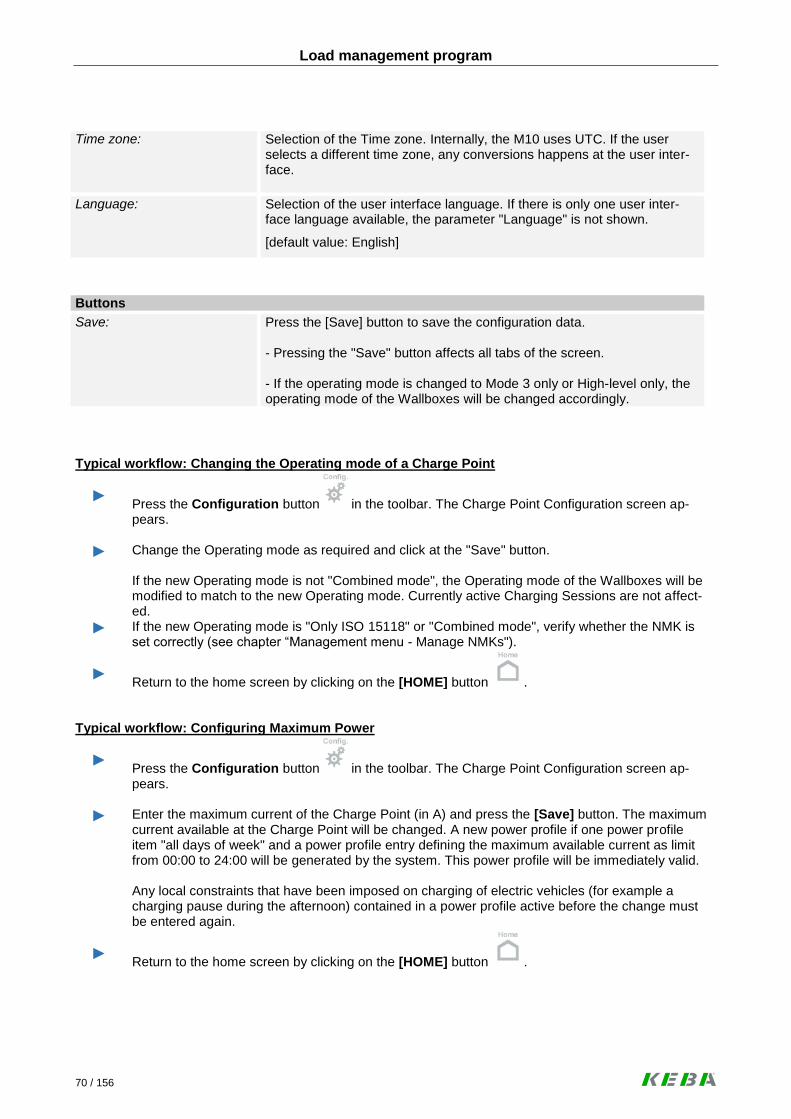
Load management program
70 / 156
Time zone:
Selection of the Time zone. Internally, the M10 uses UTC. If the user selects a different time zone, any conversions happens at the user inter-face.
Language:
Selection of the user interface language. If there is only one user inter-face language available, the parameter "Language" is not shown.
[default value: English]
Buttons
Save: Press the [Save] button to save the configuration data. - Pressing the "Save" button affects all tabs of the screen. - If the operating mode is changed to Mode 3 only or High-level only, the operating mode of the Wallboxes will be changed accordingly.
Typical workflow: Changing the Operating mode of a Charge Point
► Press the Configuration button in the toolbar. The Charge Point Configuration screen ap-pears.
► Change the Operating mode as required and click at the "Save" button. If the new Operating mode is not "Combined mode", the Operating mode of the Wallboxes will be modified to match to the new Operating mode. Currently active Charging Sessions are not affect-ed.
► If the new Operating mode is "Only ISO 15118" or "Combined mode", verify whether the NMK is set correctly (see chapter “Management menu - Manage NMKs").
► Return to the home screen by clicking on the [HOME] button .
Typical workflow: Configuring Maximum Power
► Press the Configuration button in the toolbar. The Charge Point Configuration screen ap-pears.
► Enter the maximum current of the Charge Point (in A) and press the [Save] button. The maximum current available at the Charge Point will be changed. A new power profile if one power profile item "all days of week" and a power profile entry defining the maximum available current as limit from 00:00 to 24:00 will be generated by the system. This power profile will be immediately valid. Any local constraints that have been imposed on charging of electric vehicles (for example a charging pause during the afternoon) contained in a power profile active before the change must be entered again.
► Return to the home screen by clicking on the [HOME] button .

Load management program
71 / 156
6.6.1.2 Load Management tab
Charge Point configuration – Load Management
Charge Point information
ID: Unique ID of the Charge Point. In ISO 15118-2, the ID of the Charge Point is called EVSE-ID. According to ISO 15118-2, it is a globally unique identifier containing an octet string. In communication with the Electric Vehicle, the Charge Point ID will be concatenated with the Socket ID to receive the EVSE-ID.
[default value: Charge Point ID]
Name:
Human-readable name of the Charge Point for presentation purposes.
[default value: Charge Point ID]
Charging strategy parameters
Charging strategy category:
Category of the charging strategy. Characterises the rules that will be used by the Charging Strategy. Two Charging Strategies with the same Charging Strategy Category might have different parameters.
Display values:
Fifo for fleets: Strategy for corporate fleets of EVs based on the “First come, First serve” principle.

Load management program
72 / 156
Minimum current Low-level (PWM):
The minimum current (in Ampere) that will be used during charging of Electric Vehicles controlled by basic signalling. The default is the limitation defined in IEC 61851-1. Since some Electric Vehicles require a higher minimum current, it is possible to set that amount to a higher level. Please also see: www.kecontact.com/vehicle-specifics.html for further information and configuration guidelines.
Maximum charging pause:
Maximum duration of a charging pause initiated by the Charge Point (in seconds) before the Charge Point tries to wake up the Electric Vehicle. An Electrical Vehicle was put into sleep mode, because the available power at the Charge Point was less than the minimum current low-level for that Wallbox.
Reserve previous profile? [only ISO 15118 relevant]
Indicates whether the energy agreed in a previously agreed Charging Profile will be reserved during the renegotiation of a Charging Profile.
Display values:
No: The energy will be never reserved.
EVInitiatedOnly: Energy is reserved if the renegotiation is initiated by the Electric Ve-hicle.
Always: The energy will always be reserved during the renegotiation.
Energy pricing
Unit of energy pricing: The unit of energy (such as kWh) for which a price is defined in the Pow-er Profile.
Display values:
Wh, kWh
Currency:
The currency used at the Charge Point for pricing energy. Alphabetic code from ISO 4217 (optional). Energy prices can be used to indicate preferences for times of energy delivery. The energy prices are sent to the Electric Vehicle in case of a high-level communication. The EV can use this information to charge at that point in time when the price of energy is low.
Buttons
Save: Press the [Save] button to save the configuration data. - Pressing the "Save" button affects all tabs of the screen.

Load management program
73 / 156
6.6.1.3 Authorization tab
Charge Point configuration – Authorization
Charge Point information
ID: Unique ID of the Charge Point. In ISO 15118-2, the ID of the Charge Point is called EVSE-ID. According to ISO 15118-2, it is a globally unique identifier containing an octet string. In communication with the Electric Vehicle, the Charge Point ID will be concatenated with the Socket ID to receive the EVSE-ID.
[default value: Charge Point ID]
Name:
Human-readable name of the Charge Point for presentation purposes.
[default value: Charge Point ID]
Authorization [only ISO 15118 relevant]*
Authorization enabled? Decides whether authorization is enabled at the Charge Point.
If the attribute Authorizing Charge Point is disabled, all sockets will be set to non-authorizing.
Learns charging token?
Decides whether a Charging Token can be generated, if an Electric Vehi-cle plugs into a Socket with disabled Authorization.
Note. A creation of Charging Tokens will only be done for some types of Charging Tokens such as PEV-IDs.

Load management program
74 / 156
Automatically accepts token?
Decides whether a Charging Token is generated by plugging in an Elec-tric Vehicle into a Socket with enabled Authorization.
Automatic acceptance dura-tion:
Default value for the number of days until expiration of a Charging Token that will be automatically created.
Default expiry period:
Default value for the number of days a Charging Token will be considered accepted if no expiration date is delivered to the Charge Point when au-thenticating the Charging Token.
May change imported white lists?
Indicates whether it is possible to edit imported white lists.
(*) This options are only active if “Authorization enabled?” = “Yes”.
Buttons
Save: Press the [Save] button to save the configuration data. - Pressing the "Save" button affects all tabs of the screen. -Generate Charging Tokens, Acceptance Duration and Automatically accepts token are only relevant for Charge Points that authorizes using PEV-ID.
Additional information: The KeContact M10 provides functions to ensure that only drivers entitled to use the charge point may charge their electric vehicles. The following mechanisms are supported:
RFID: The user may swipe a RFID contained in the white list of the KeContact M10. If the KeContact M10 is connected to an optional central administration system using its OCPP system management in-terface, the KeContact M10 will inquire the white list of the central system if the RFID is not contained in the white list of the KeContact M10.
EVCCID (PEV-ID): The KeContact M10 supports ISO/IEC 15118 Plug&Charge using a vehicle ID (PEV-ID or in newer versions of the ISO/IEC 15118 standard EVCCID). During setup of an ISO/IEC 15118 charging session, the KeContact M10 compares the vehicle ID passed by the electric vehicle with its in-ternal white list. As with RFIDs, the KeContact M10 can also inquire the white list of a central manage-ment system if the vehicle ID is not contained in the internal white list of the KeContact M10.
GUI: The KeContact M10 provides a GUI screen allowing a system administrator to approve an electric vehicle for charging. For example, this can be used if the driver has forgotten her or his RFID.
Central System: A central system may approve an ongoing charging session that could not be author-ized locally using the OCPP system management interface. For example, this can be used from a call centre.
The charging tokens (RFID or vehicle ID) that can be used to authorize a charging session are maintained in a white list stored at the KeContact M10. A white list entry may be entered at the GUI of the KeContact M10, imported from a file that is uploaded from the Web GUI or at the OCPP system management interface of the KeContact M10. In addition, it is possible to "teach" vehicle IDs to a KeContact M10. It is possible to switch off authorization for a charge point or an individual Wallbox.

Load management program
75 / 156
Typical workflow: Enable/ Disable Authorization (Charge Point)
► Press the [Configuration] button in the toolbar at the bottom of the screen. The charge point configuration screen appears.
► Select the tab “Authorization”.
► Check or uncheck the checkbox "Authorization enabled". If the checkbox is unchecked, authoriza-tion for all Wallboxes will be disabled. Already authorized charging sessions will not be affected by the change of the authorization policy of the Wallbox.
► Press the [Save] button to save the settings.
► Return to the home screen by clicking on the [HOME] button .
6.6.1.4 Metering and Power control tab
Charge Point configuration – Metering and Power control

Load management program
76 / 156
Charge Point information
ID: Unique ID of the Charge Point. In ISO 15118-2, the ID of the Charge Point is called EVSE-ID. According to ISO 15118-2, it is a globally unique identifier containing an octet string. In communication with the Electric Vehicle, the Charge Point ID will be concatenated with the Socket ID to receive the EVSE-ID.
[default value: Charge Point ID]
Name:
Human-readable name of the Charge Point for presentation purposes.
[default value: Charge Point ID]
Metering
Publishes meter values?
Decides how intermediate meter reading will be handled.
Display values:
No: Intermediate meter readings will neither be stored in the Charging Transaction nor written to a log file.
Most recent: The most recent intermediate meter reading will be stored at the Charging Transaction, but no log file entry will be written.
Full log: The most recent intermediate meter reading will be stored at the Charging Transaction and written to the log file.
Metering period:
Duration in seconds between two consecutive intermediate meter read-ings. The period may not be smaller than 5 seconds. Recommendation: Due to the high data amount, do not enter a short me-tering period for a long time.
Meter collection type:
Type of collection of meter readings for export.
Display values:
ClockAligned: Meter readings will be generated for Sockets or the Charge Point. They will be collected in evenly spaced intervals starting from mid-night.
Sampled: Meter readings will be generated for Charging sessions. They will be collected at the start and end of the Charging session as well as in evenly spaced intervals starting from the start of the Charging ses-sion.
Both: Both clock-aligned and sampled Meter readings will be collected.
Collection interval clock aligned:
Size (in seconds) of the clock-aligned data interval. This is the size of the set of evenly spaced aggregation intervals per day, starting at 00:00:00 (midnight). Optional. Must be populated, if Meter Collection Type = ClockAligned or Both.
Collection interval session aligned:
Interval (in seconds) between sampling of metering data, intended to be exported. Sampling starts at the begin of the Charging session. Optional. Must be populated, if Meter Collection Type = Sampled or Both.

Load management program
77 / 156
Power control
Power control action:
Defines, whether the Charge Point controls the level of power drawn by the Electric Vehicle.
Display values:
No action The Charge Point doesn't control power levels drawn by the Electric Vehicles connected to the Charge Point.
Only logging The Charge Point logs, if an Electric Vehicle exceeds the assigned power levels.
When outside global limits The Charge Point disconnects an Electric Vehicle exceeding its as-signed power levels, if the power used by all Electric Vehicles ex-ceeds the power made available to the Charge Point.
Always The Charge Point disconnects an Electric Vehicle if it exceeds the assigned power levels.
Tolerance power control:
Level of current (in Ampere) by which the power must exceed the as-signed power level before the power control takes action.
Max excess count ISO 15118:
Maximum number of measurements at which the assigned power level must be exceeded during charging control using high-level communica-tion, before power control takes action.
Max excess count low-level:
Maximum number of measurements at which the assigned power level must be exceeded during Mode 3 charging, before power control takes action.
History repeated violations:
Decides if multiple session history entries will be written if an Electric Vehicle exceeds the assigned power level multiple times or if a session history entry will only be written the first time.
Typical workflow: Configure meter value collection
► Press the [Configuration] button in the toolbar at the bottom of the screen. The charge point configuration screen appears.
► Select the tab “Metering and Power Control”.
► Update the meter reading settings and press the [Save] button.
► Return to the home screen by clicking on the [HOME] button .

Load management program
78 / 156
Typical workflow: Configure power control
► Press the [Configuration] button in the toolbar at the bottom of the screen. The charge point configuration screen appears.
► Select the tab “Metering and Power Control”.
► Update the power control settings and press the [Save] button.
► Return to the home screen by clicking on the [HOME] button .
Typical workflow: Manage power control
► An electric vehicle has been blocked because of power control. Use the monitoring screens to analyze the situation (see “Monitor Charging sessions”).
► If the electric vehicle has been blocked because of an incorrect configuration, correct the power control settings (refer to workflow “Configure Power Control”).
► Depending on the results of the analysis, unblock the charging session. If a vehicle is unblocked that has been blocked by power control, Power control might block the electric vehicle again if it still doesn’t follow the rules. Unblocking therefore only make sense in case of a temporary violation or after the settings for power control have been modified.
► Return to the home screen by clicking on the [HOME] button .

Load management program
79 / 156
6.6.2 Wallbox configuration
These screens allow the configuration of the Wallbox parameters.
6.6.2.1 Configure Wallbox tab
This screen shows Wallbox parameters that can be changed at the user interface.
Wallbox configuration – Configure Wallbox
Select Wallbox for configuration
Wallbox Number: The drop down box shows the socket number of all Wallboxes that are visible at the home screen. If the user changes the Wallbox number, the screen is shown for the Wallbox selected by the user. If no Wallbox is passed to the screen, Wallbox 1 will be selected.
Charge Point information
Charge Point operating mode:
Describes whether the Charge Point allows Mode 3 charging controlled by basic signalling, charging controlled by high-level communication or both.
Authorization enabled?
Shows whether authorization is enabled at the Charge Point.

Load management program
80 / 156
Wallbox configuration
Wallbox operating mode:
Describes whether the Wallbox allows Mode 3 charging controlled by basic signalling, charging controlled by high-level communication or both.
The Operating mode Wallbox can only be changed if the Charge Point operates in "Combined mode". Otherwise, the operating mode of the Wallbox must be the same than the operating mode of the Charge Point.
Values:
Only basic signalling (Mode 3 only): Only Mode 3 charging controlled by basic signalling according to IEC 61851-1 is possible.
Only ISO 15118: Only vehicles using high-level communication can be charged.
Combined mode: Both Mode 3 charging and charging with high-level communication is supported.
[default value: Combined mode]
Requires authorization?
Decides whether authorization is required at the Wallbox.
Enabling Authorization is only possible if Authorizing Charge Point is en-abled.
Buttons
Save: Press the [Save] button to save the configuration data. - Changes will not have an impact on currently active sessions.
Typical workflow: Changing the Operating mode of a Wallbox
► Press the [Configuration] button in the toolbar. The Charge Point Configuration screen appears.
► Click at the button [Wallbox] in the menu bar at the left side of the web page. The wallbox con-figuration screen appears.
► Select the number of the wallbox for which the operating mode shall be changed.
► Change the operating mode as required and click at the [Save] button. If a charging session is currently active at the wallbox, this will not be affected by the new operating mode of the wallbox.
► Return to the home screen by clicking on the [HOME] button .

Load management program
81 / 156
Typical workflow: Enable/ Disable Authorization (Wallbox)
► Press the [Configuration] button in the toolbar at the bottom of the screen. The charge point configuration screen appears.
► Click at the button [Wallbox] in the menu bar at the left side of the web page. The Wallbox con-figuration screen appears.
► Select the number of the Wallbox for which authorization will be enabled or disabled.
► Check or uncheck the check box "Requires authorization?" as required. Already authorized charging sessions will not be affected by the change of the authorization policy of the Wallbox.
► Press the [Save] button to save the settings.
► Return to the home screen by clicking on the [HOME] button .
6.6.2.2 Preconfigured Parameters tab
This screen shows Wallbox parameters reported by the firmware of the Wallbox (read only). A change re-quires a firmware update or other DIP switch settings.
Wallbox configuration –Preconfigured Parameters

Load management program
82 / 156
Identification
Wallbox Number: The drop down box shows the socket number of all Wallboxes that are visible at the home screen.
If the user changes the Wallbox number, the screen is shown for the Wallbox selected by the user. If no Wallbox is passed to the screen, Wallbox 1 will be selected.
Model name Wallbox: Model name of the Wallbox.
Display value:
KeContact P20
Wallbox serial number: Serial number stored in the EPROM of the Wallbox.
EVSE-ID for ISO 15118: ID of the Socket to be used when communicating with the Electric Vehi-cle. The Charge Point ID will be concatenated with the Socket ID to re-ceive the EVSE-ID.
Details
Firmware version Version of the firmware deployed at the Wallbox.
Maximum available current: Maximum energy level available by charging at the Wallbox (in Ampere).
Number of phases: Number of phases supported by the Wallbox (must be 1 or 3).
Phase used: The phase to which the Wallbox is connected for single-phase charging.
Display values:
L1, L2, L3.
Fixed cable? Wallbox with fixed cable:
Display values:
Yes / No.
IP address (Wallbox):
IP address of the Wallbox.
Values: 192.168.25.xxx (where xxx is the Socket ID)
Ventilation supported? Indicates whether ventilation is supported.
Display values:
Yes / No.
Requires authorization? Indicates whether authorization is enabled at the Wallbox.
Display values:
Yes / No.

Load management program
83 / 156
6.6.3 Power Profile configuration
Overview screen that shows all existing Power Profiles.
Configuration menu - Power Profiles
Power Profile details
Valid from: Point in time at which the validity of a power profile begins. A Power Pro-file remains valid until its successor gets valid.
Special Day: Special day at which the Power Profile overrides the currently active Power Profile.
Max. Current [A]: Maximum current (in Ampere) that can be offered in aggregate to all Elec-tric Vehicles connected to the Charge Point when the Power Profile is applicable.
System generated? Indicates whether the Power Profile is system generated. If you change the Maximum current, a new “system generated” Power Profile will be created.
DSO generated? Indicates whether the Power Profile is DSO (OCPP) generated.

Load management program
84 / 156
Power Profile details
Status: Indicates whether a power profile is superseded, active or for future use.
Display values:
The power profile is in the database for future use.
The power profile is not in use because currently, a power profile for a special day is active. The power profile will turn back active after the special day has passed.
The power profile is currently being used.
The power profile was active in the past, but has been replaced by another active power profile.
The power profile is not correct. This can happen if the maximum available power for the KeContact M10 system has been changed.)
Buttons
New: Press the [New] button to create a new Power Profile.
Delete: Press the [Delete] button to delete the selected Power Profile.
- Deleting a profile requires a confirmation by the user.
- Deleting is only possible for Power Profiles in state "Future" or "Error" and only for Power Profiles that are not system generated.
- Deleting is not possible for currently active or used Power Profiles.
View: Press the [View] button to show the selected Power Profile.
Edit: Press the [Edit] button to change the selected Power Profile. - Editing is only possible for Power Profiles in state "Future" or "Error" and only for Power Profiles that are not system generated.
Copy: Press the [Copy] button to copy the selected Power Profile. - The Power Profile will only be persistent if it is saved in the “Edit Power Profile” screen.
Additional information:
The load management functionality of the KeContact M10 distributes the energy available at an access point to the electricity grid to all electric vehicles connected to the charge point. Technical characteristics of the electric vehicle such as the maximum power than can be drawn by the charger inside the electric vehicle, the number of phases, the maximum current that can be carried by the cable between the electric vehicle and the outlet of the charge point managed by the KeContact M10, the requested energy, the expected time of departure, ... will be taken into account if this information is available at the charge point. The energy that can be distributed to the electric vehicles connected to the charge point is restricted as fol-lows: The KeContact M10 maintains a limit for the current at the access line to the electricity grid (maximum available current) that may not be exceeded for technical reasons. Typically, a circuit breaker will trip if the sum of all currents drawn by the electric vehicles connected to the charge point exceeds this limit.

Load management program
85 / 156
A power profile can be entered at the GUI of the KeContact M10 that contains further limits that depend on the time of day and the type of day. Those limits can be used to ensure that electric vehicles are charged at a point in time when energy is less expensive or to reserve certain periods of the day for other energy con-sumers. If no power profile is entered at the GUI, a default power profile is used that always offers the maxi-mum available current. The following picture shows an example power profile:
A power profile consists of one or more power profile items that apply to one or more days of week. Every power profile item consist of one or more power profile entries giving the maximum current availa-ble at a particular time interval. A power profile is valid until the start of validity of a new power profile. A Power Profile only expires if there is another Power Profile which becomes active in the future. Active or expired power profiles may not be changed. A power profile may only be valid for a special day such as Easter Monday. After the end of the special day, the previously active power profile will be reactivated again.

Load management program
86 / 156
Typical workflow: Scheduling available energy (new Power Profile)
► Press the [Configuration] button in the toolbar at the bottom of the screen.
► Click at the button [Power Profile] in the menu bar at the left side of the web page. The power profile configuration screen appears.
► Press the [New] button below the table of the available power profiles. The power profile editor screen appears.
► Enter the details about the power profile (valid from, special day ...). One after the other enter details about the power profile items. Previously entered power profile items can be selected from the drop down box with the label "Power Profile Item Name". For a power profile item, enter the power profile entries into the table "power profile entries".
► Press the [Save] button to save the Power profile.
► Return to the home screen by clicking on the [HOME] button .

Load management program
87 / 156
6.6.4 Edit Power Profile
Screen to edit a Power Profile.
Configuration menu - Edit Power Profile
Power profile
Valid from:
Point in time at which the validity of a Power Profile begins. A Power Pro-file remains valid until its successor gets valid.
[DD.MM.YYYY]
Special day:
Special day at which the Power Profile overrides the currently active Power Profile. The “Special day” function can not be used together with the “Valid from” date.

Load management program
88 / 156
Reserved for ISO 15118: [Only in combined mode ac-tive]
Percentage of the Maximum Current Offered that is reserved for Electric Vehicles using high-level communication.
[Maximum is 100%]
100% means that the complete available power of the M10 is reserved for ISO 15118 vehicles, even if Mode 3 vehicles want to charge.
Maximum current Charge Point:
Max available current (in Ampere) that is available at the Charge Point. Most likely, this is a limitation determined by the power delivery contract of the organization.
Power profile items
Power profile item name: Name of the Power Profile for presentation purposes.
The dropdown box contains all values contained in the database and a value to indicate "new". If "New power profile item name" is selected, a screen with an empty item will be presented to enter a new Power Profile item name.
Power profile entries
Item name:
Name of the Power Profile Item.
Days of week:
Days of the week at which the Power Profile is valid. (Monday, Tuesday, Wednesday,….)
From / To:
Time period from / to the Power Profile is valid. The “Valid from” date must be in the future and may not be identical to the “Valid from” date of other Power Profiles.
Max. Current [A]:
Maximum current for this Power Profile. This value may not exceed the Maximum Current of the Charge Point.
Price:
Energy price during this Power Profile. The price may not be negative.
Current 15118 [A]:
Current (in Ampere) that is reserved for charging by vehicles using high-level communication. This value may not exceed the Maximum Current of the Charge Point.
Optional: If no value is set, the value will be calculated as follows: “Reserved for ISO 15118” x “Max current” / 100
Buttons
Save: Press the [Save] button to save the Power Profile settings.
Additional information: You are able to edit a Power Profile only if the Power Profile was not active in the past or is not currently active.

Load management program
89 / 156
Edit Power Profile Items
Power profile item
Power Profile Item name: Name of the Power Profile Item.
Start time: Start time of the Power Profile Item.
End time: End time of the Power Profile Item.
Max. current offered:
Maximum current for this Power Profile Item. This value may not exceed the Maximum Current of the Charge Point.
Price: Energy price during this Power Profile Item. The price may not be nega-tive.
Maximum current for ISO 15118:
Current (in Ampere) that is reserved for charging by vehicles using high-level communication. This value may not exceed the Maximum Current of the Charge Point.
Valid at…
Days of week: Days at which the Power Profile Item is valid. At least one day of the week must be selected.
Values:
Monday, Tuesday, Wednesday, Thursday, Friday, Saturday, Sunday
Buttons
Update: Press the [Update] button to save the new Power Profile Item settings.

Load management program
90 / 156
Typical workflow: Scheduling available Energy (existing Power Profile)
► Press the [Configuration] button in the toolbar at the bottom of the screen.
► Click at the button [Power Profile] in the menu bar at the left side of the web page. The power profile configuration screen appears.
► Select the power profile that shall be changed in the table and press the [Edit] button below the table of the available power profiles. The power profile editor screen appears.
► Enter the details about the power profile (valid from, special day ...) if necessary. Select the power profile item to be changed from the drop down box with the label "Power Profile Item Name" or enter the name of a new power profile item. Change the details about the power profile item if necessary. If necessary, change the power profile entries in the table "power profile entries".
► Press the [Save] button to save the Power profile.
► Return to the home screen by clicking on the [HOME] button .

Load management program
91 / 156
6.6.5 View Power Profile
Configuration menu - View Power Profile
Power profile
Valid from:
Point in time at which the validity of a Power Profile begins. A Power Pro-file remains valid until its successor gets valid.
Special day:
Special day at which the Power Profile overrides the currently active Power Profile.
Reserved for ISO 15118:
Percentage of the Maximum Current Offered that is reserved for Electric Vehicles using high-level communication.
Maximum current Charge Point:
Max available current (in Ampere) that is available at the Charge Point. Most likely, this is a limitation determined by the power delivery contract of the organization using the M10 system.
Power profile entries
Days of week: Days at which the Power Profile is valid.
From / To:
Time period from / to the Power Profile is valid.
Max. Current: Maximum current for this Power Profile.
Price: Energy price during this Power Profile.
Current ISO 15118:
Current (in Ampere) that is reserved for charging by vehicles using high-level communication.

Load management program
92 / 156
6.7 Installation menu
Press the [Installation] button to show the “Installation menu”.
Menu to enter details necessary to parameterize a working KeContact M10 system. There are two variants of the installation process:
First time installation: This is the initial installation of a Charge Point. After the installation, the Charge Point is operational.
Please find the detailed description of the installation process in chapter “First time installation -> Installation menu”.
Update installation: An update installation is required if a Wallbox is added, the IP address set by the DIP switches of the Wallbox is changed or the capacity of the connection to the power grid is changed.
Installation menu

Load management program
93 / 156
In the following, the Update installation is described:
► Install the new Wallbox or perform the required changes as described in chapter “Hardware in-stallation”.
► Switch on all hardware components.
Depending on your system, it may take a few minutes until the KeContact M10 is completely in operation. The progress of the KeContact M10 startup is displayed at the MMI menu:
- Power-on self test (POST)…
- Starting OS…
- MMI main menu loading…
- Date / time and IP address…
The access to the installation mode of the web application is now possible.
► Only when installing a new Wallbox or changing the IP addresses using the DIP switches, please start the “Rescan sockets” function via the MMI menu of the KeContact M10. This function de-tects the connected Wallboxes.
► Connect your notebook to the KeContact LAN [ETH0].
Connection via port ETH0:
Type in the IP address http://192.168.25.1:9091/admin of the KeContact M10 in the ad-
dress bar of your web browser (an open port “9091” is required to get access to the application). Please save the settings using ETH0 otherwise an ETH1 connection is not possible.
► Enter Username and Password of a user that has access to the installation menu. This information can be obtained from the system administrator of the Charge Point.
► Change the required data in the “Installation menu” and save the installation data.
Please see chapter “First time installation” for further information.

Load management program
94 / 156
Parameters
ID: Unique ID of the Charge Point. In ISO 15118-2, the ID of the Charge Point is called EVSE-ID. According to ISO 15118-2, it is a globally unique identifier containing an octet string. In communication with the Electric Vehicle, the Charge Point ID will be concatenated with the Socket ID to receive the EVSE-ID.
[default value: Charge Point ID]
Name:
Human-readable name of the Charge Point for presentation purposes.
[default value: Charge Point ID]
Charge point Operator:
Human-readable name of the operator of the Charge Point.
[default value: empty]
Nominal Voltage:
Voltage (in Volt) used for calculations of power. Refers to a single phase (e.g. 230V in continental Europe).
Valid single line nominal voltage values are: 110, 115, 120 (USA), 127, 208, 220, 230 (Europe), 240
Maximum current Charge point:
Maximum available current (in Ampere) that is available at the Charge Point. Most likely, this is a limitation determined by the power delivery contract of the organization using the M10 system.
A new power profile will be created upon first entry of “Max. Available Current” or if this value is changed by using this screen.
If the install screen is used to change the “Max. Available Current” and there are future-dated power profiles that offers more current than “Max. Available Current”, those power profiles will be set to "Error" and can no longer be used until they have been corrected. The state might change if “Max. Available Current” is increased again or if the power profile is changed.
[Max. Available Current shall be between 16A and 480A (=15x32A)]
Charge Point operating mode:
Describes whether the Charge Point allows Mode 3 charging controlled by basic signalling, charging controlled by high-level communication or both.
Values:
Only basic signalling (Mode 3 only): Only Mode 3 charging controlled by basic signalling according to IEC 61851-1 is possible.
Only ISO 15118: Only vehicles using high-level communication can be charged.
Combined mode: Both Mode 3 charging and charging with high-level communication is supported.
[default value: Combined mode]
Authorization enabled?
Indicates whether authorization is enabled at the Charge Point.
[default value: disabled]

Load management program
95 / 156
Internet access? [only ISO 18118 relevant]
Indicates whether internet access is possible for the Electric Vehicle at the Charge Point.
[default value: disabled]
Measurement system:
Selection of the measurement system. Internally, the Load management program uses the metric system. If the user selects the US system, any conversion happens at the user interface.
Values:
Metric: Metric measurement system (meter, degree Celsius,…).
US: US measurement system (yard, degree Fahrenheit,…).
[default value: Metric]
Time zone:
Selection of the Time zone. Internally, the Load management program uses UTC. If the user selects a different time zone, any conversions hap-pen at the user interface.
Language:
Selection of the user interface language. If there is only one user inter-face language available, the parameter "Language" is not shown.
[default value: English]
Buttons
Save: Press the [Save] button to save the installation data.

Load management program
96 / 156
6.8 Management menu
Press the [Management] button to show the “Management menu”.
Screens in this group support the operation of the KeContact M10 (e.g. manage accounts, meter readings or white lists).
Management menu

Load management program
97 / 156
6.8.1 Charging session
Screen for Stopping and Resuming of running charging sessions.
Management menu – Charging sessions
Session entries
Wallbox: Shows the socket number of the Wallbox.
Start: Point in time when the charging session started.
Planned End: Planned end of charging as communicated by the Electric Vehicle during charge parameter discovery in high-level communication.
Type: Describes whether the Charging Session is a Mode 3 charging session or a high-level charging session.
Display values:
Basic signalling: Mode 3 charging according to IEC 61851-1 controlled by basic signal-ling.
ISO 15118: Charging session controlled by high-level communication.

Load management program
98 / 156
State:
Shows the state of the current Charging Session.
Display values:
Not plugged in: No electric vehicle is connected to the Wallbox.
Standby: The vehicle is connected, but on standby.
Charging: The vehicle is charging or in a charging pause and the vehicle is not blocked.
Blocked: The vehicle has been blocked by the Wallbox or no active charging transaction exists.
Error: The socket is degraded or fatal.
Authorization?
Indicates whether the Charging session is authorized.
Display values:
Yes/No
Authorization Type:
Type of the identification of the holder of the Charging Token.
Display values:
PEV-ID: The token holder is identified by a PEV-ID.
RFID: The token holder is identified by a RFID.
Manual: The session has been authorized via the Graphical User Interface.
Host: A Charging session has been authorized by the host using a Remote Start Transaction message (OCPP) or equivalent.
Authorization token:
ID of the charging token (either PEV-ID or Token RFID or Session Se-quence ID). Session Sequence ID will be used for manually generated charging tokens.
Authorization:
Approval reason: The reason entered via a free text field when manually approving a Charging Session.
- The “Approval reason” will be ignored unless the [Authorize] button is pressed and is stored just for information purposes.
Buttons:
View details: Press the [View details] button to show the “Charging session details” screen.
Unblock: Press the button [Unblock] button to unblock a blocked session, the Elec-tric Vehicle may resume charging.
Block: Press the [Block] to switch a session into the (internal) session state “blocked”. The Electric Vehicle stops charging.
Authorize: If the session has not yet been authorized and the button [Authorize] is pressed, then the Electric Vehicle is authorized to start charging.
- "Authorize" is only possible if the session is in state "Waiting for Authori-zation".

Load management program
99 / 156
Typical workflow: Authorize Charging Sessions
► Press the [Management] button in the toolbar. The Management screen (Charging Session Management) appears.
► Select the charging session to be authorized, enter the approval reason and press the button [Authorize].
► To optionally view the details about the authorization, press the [Refresh] button in the toolbar at the bottom of the screen.
► Return to the home screen by clicking on the [HOME] button .
Typical workflow: Manage Charging Sessions
► Press the [Management] button in the toolbar. The Management screen (Charging Session Management) appears.
► This screen provides an overview of the ongoing charging sessions. By selecting a charging ses-sion and pressing one of the buttons below the table showing the charging sessions, manage-ment operations (blocking, unblocking, authorization) can be performed and details about the charging sessions can be reviewed. If the button [View Details] is pressed, detailed information about the charging session that has been selected is shown. If the button [Unblock] is pressed, a blocked charging session starts charging again. This button doesn’t work for charging sessions that have not yet been authorized. If the button [Block] is pressed, a working charging session stops charging. This button doesn’t work for charging sessions that have not yet been authorized. If the button [Authorize] is pressed, a charging session that has not yet been authorized is au-thorized.
► Because most data shown at the screens are static, the screens will not be refreshed.
Up to date information can be loaded by clicking on the [Refresh] button .
► Return to the home screen by clicking on the [HOME] button .

Load management program
100 / 156
6.8.1.1 Charging session details
This screen shows the “Charging session details”. The content of this screen is currently identical to the “Session History” screen in the Monitoring menu.
► To show this screen, select a charging session in the “Charging Sessions” screen and press the [View Details] button.
Management menu – Charging session details
Session
Session ID: Unique identifier of the Charging Session.
Wallbox number: Socket number of the Wallbox.
Session start time: Point in time when the Charging Session has started.
Session end time: Point in time when the Charging Session has ended.

Load management program
101 / 156
Session history table
History type:
Type of the history entry.
Display values:
Start session A Charging Session has started.
Resume session A charging session has been resumed by the Electric Vehicle.
End session A Charging Session has ended.
Start transaction A Charging Transaction has started.
Start system transaction A new charging transaction has been started by the system because of an exceptional condition such as Charge Parameter Discovery without Power Delivery Request while high-level communication.
End transaction A Charging Transaction has ended.
Power exceeded The Electric Vehicle has drawn more power than assigned in the Charging Profile or at the Wallbox.
Renegotiation A renegotiation has been initiated because the Electric Vehicle has exceeded the electric current assigned in the Charging Profile.
No ventilation The Electric Vehicle has requested ventilation, but the Wallbox doesn't support ventilation.
Time:
Timestamp of the entry into the session history.
Meter reading:
Meter reading in the transaction history. Might be from different attributes depending on the type of transaction.
Termination:
Termination reason at the session history. Might be either “Termination Reasons Session” or “Termination Reason Transaction” depending on the type of history entry.
Details:
Detailed information contained in the session history.
It will be populated with additional information such as "Contract ID" for the start of a session or the measured current in case of exceeding the assigned current.

Load management program
102 / 156
6.8.2 Manage Accounts
Screen to manage (create, change, delete) user accounts.
Management menu – Account Details
Account details and password change
User name: Unique name identifier of the user account.
Account description:
More detailed text description of the user account.
Password:
Case sensitive password for the user account.
If a new user account is created, a password is required.
Repeat password:
Field to enter the password the second time if the user or an administra-tor wants to enter or change a password. The two password fields must be equal in order to be accepted by the software.
Access rights
Installation screen: The user is authorized to access the installation screen.
Configuration menu: The user is authorized to access the Configuration menu.
Management menu:
The user is authorized to access the Management menu.
The access to the management menu doesn't automatically permit the access to the account management screens. This requires special user rights (Access Account Management).

Load management program
103 / 156
Service menu: The user is authorized to access the Service menu.
Account Management:
The user is authorized to access the Account Management screen.
Enable this function in order to allow the user to create, change or delete user accounts.
Buttons
Delete: Press the [Delete] button to delete the user account data belonging to the User name. Deleting the administrator account is not possible.
Save: Press the [Save] button to save the User account data that are currently on the screen.
- If there is no entry with the same User name in the database, a new account will be created.
- The Save button will replace an existing account with the same User name. If no new password has been entered, the old password in the database will be used.
Search: Press the [Search] button to open the “Select Account” screen.
Read: Press the [Read] button in order to retrieve the stored account data be-longing to the User name.
Typical workflow: Manage accounts
► Press the [Management] button in the toolbar.
► Press the button [Manage Accounts] at the left side of the screen. The account details screen appears.
► You can either enter the details for a new account or work with an existing account: New Account: Enter a new user including its password and access rights and press the [Save] button. Existing Account: As first step of working with an existing account, get the details of the account onto the screen by entering the username and press the [Read] button.
► If the exact username for the account to be processed is not known, you can find it by pressing the [Search] button. The select account screen appears. Select the account and press the [Select] button. The username will be transferred to the ac-count management screen.
► Change the existing account and press the [Save] button. If you want to delete the account rather than changing it, press the [Delete] button.
► Please press the [Logout] button in the toolbar after performing the work in the password protected area. The HOME screen appears.

Load management program
104 / 156
6.8.3 Select Account
Press the [Search] button in the “Manage Account” screen to open the “Select Account” screen.
Management menu – Select account
User accounts
User name:
Name of the user account.
Description:
Description of the user account.
Buttons
Select: Select a user account and press the [Select] button to open the Manage Account screen for the selected user.

Load management program
105 / 156
6.8.4 View Meter Readings
Screen to view the meter values collected overall and by socket.
Management menu – View Meter Readings
Metering Criteria
Publishes meter values? Indicates how intermediate meter reading will be handled.
Display values:
No Intermediate meter readings will neither be stored in the Charging Transaction nor written to a log file.
Most recent The most recent intermediate meter reading will be stored at the Charging Transaction, but no log file entry will be written.
Full log The most recent intermediate meter reading will be stored at the Charging Transaction and written to the log file.
Metering period: Duration in seconds between two consecutive intermediate meter read-ings.

Load management program
106 / 156
Select meter values for viewing
Wallbox: Selection attribute for the Socket ID. Contains all valid socket numbers and "all".
Meter reading type: Indicates metering readings of which types shall be shown. Only meter readings matching those criteria will be presented (e.g. “all”, “Start Transaction”, “Transaction aligned”,…).
Meter readings table
Wallbox: The drop down box shows the socket number of all Wallboxes that are visible at the home screen.
Timestamp: Timestamp of the meter reading. Might be from different attributes de-pending on the type of meter reading.
Type: Type of meter reading.
Display values:
Start Transaction Meter reading at the start of a charging session.
End Transaction Meter reading at the end of a charging session.
Intermediate Meter reading during a charging session.
Transaction aligned socket
Clock aligned charge point
Meter readings can be either periodic (for example every ten or fifteen minutes) or related to a charging transaction (primarily if ISO 15118 is used). The attribute Metering Period determines how often meter read-ings will be collected. According to ISO 15118, meter readings have to be collected at the beginning and the end of a charging transaction as well as frequently during the charging process (intermediate meter readings).
Value [Watth]: Value of the meter reading. Might be from different attributes depending on the type of meter reading.
Buttons
Export: Press the [Export] button to show the “Download meter readings” screen.
Typical workflow: View meter values
► Press the [Management] button in the toolbar.
► Press the menu button [Meter Readings] at the left side of the screen. Review the current meter readings of the wallbox.
► The data shown at the meter readings screen will not be refreshed. Up to date information can be loaded by clicking on the [Refresh] button at the bottom of the screen.
► Return to the home screen by clicking on the [HOME] button .

Load management program
107 / 156
6.8.4.1 Download meter readings
Screen to export the meter values to a file either on an USB stick or in a directory. The screen lists all creat-ed meter reading archives.
► To show this screen, select an item in the “View Meter Readings” screen and press the [Export] button.
Management menu – Download Meter Readings
Meter reading archives
Time created: Creation timestamp of a meter reading archive (local time).
Size (kB): Size of a meter reading archive (in kB).
Buttons
Delete: Press the [Delete] button to delete the selected meter reading archives.
Download: Press the [Download] button to download the selected meter reading archive. A dialogue box appears that allows to specify a location for the download.
New: Press the [New] button to create a new archive. All currently available meter readings will be collected and packaged into a new zip-archive. The archive will be shown at the archive table at this screen and can be downloaded from this screen.

Load management program
108 / 156
Meter readings file description
The meter readings file (*.xls) is intended to use by all customers. The meter readings file can be download-ed in the “Management menu – Meter readings” screen and contains all stored meter values. Detailed field description
(example of a meter readings file)
Field Description
A Socket number
B Meter reading type
C Charging session ID
D Transaction ID
E Entry time stamp
F Meter value (Energy consumed) Meter value/1000 = Wh
G Token ID: Shows the authorization token which has authorized the charging session. If no token is asso-ciated to a charging session, then the Wallbox does not require an authorization.
Typical workflow: Export meter values
► Press the [Management] button in the toolbar.
► Press the menu button [Meter Readings] at the left side of the screen.
► Press the [Export] button. The location to store the meter reading can be defined in the dialogue boxes that pops up after pressing the “Export” button.
► Return to the home screen by clicking on the [HOME] button .

Load management program
109 / 156
6.8.5 Manage White list
Screen to manage white lists of charging tokens.
Management menu – White List
Search White list
Token type: Selection attribute for the token type (e.g. “all”, “PEVID”, “RFID”,…).
Token ID (prefix):
Prefix of the Token ID to be selected.
[Default value: empty]
Token status: Selection attribute for the token status (e.g. “all”, “accepted”, “blocked”,…)
[Default value: “all”]
White list table
Token type: Type of the identification of the holder of the Charging Token.
Display values:
PEV-ID: The token holder is identified by a PEV-ID which is used by a high-level communication.
RFID: The token holder is identified by a RFID.
Manual: The session has been authorized via the Graphical User Interface.
Host: A Charging session has been authorized by the host using a Remote Start Transaction message (OCPP) or equivalent.

Load management program
110 / 156
Token ID:
ID of the charging token (either PEV-ID or Token RFID or Session Se-quence ID). Session Sequence ID will be used for manually generated charging tokens.
Status: Status of the charging token. All states except “Accepted” are considered as “not able to authorize”.
Display values:
Accepted: The Charging Token is accepted. It can be used to authorize a charg-ing session.
Blocked: The Charging Token has been blocked by an administrator or by the system. The Blocking reason contains information about the Reason of the blocking.
Expired The Charging Token has been authorized, but the authorization has expired.
Invalid: The Charging Token has been recognized as invalid.
Pending: The Charging Token is waiting for acceptance.
Overwritten: The Charging Token has been (logically) deleted by an OCPP mes-sage. It cannot be used for authorizing charging sessions. It is in the data store of the KeContact server as long as there are any historical charging sessions. Overwritten Charging Tokens will be purged dur-ing housekeeping.
Status time:
Timestamp of the last status change of the Charging Token.
Expires:
The last day the Charging Token is valid.
Version:
Version number of a white list. It is only populated if the Charging Token was imported from a file or from an external system. This attribute will be updated each time a change for the Charging Token will be imported.
Buttons
Import: Press the [Import] button to import a white list of charging tokens from a file.
Change: Press the [Change] button to change the selected charging token.
New: Press the [New] button to create a new charging token white list.
Unblock: Press the [Unblock] button to set a blocked charging token status to “Ac-cepted”.
Block: Press the [Block] button to set the charging token status to “Blocked” (status “Accepted” is required).
Accept: Press the [Accept] button to set the charging token status to “Accepted” (status “Pending” is required).

Load management program
111 / 156
Typical workflow: Manage White list items
► Press the [Management] button in the toolbar. The Management screen (Charging Session Management) appears.
► Click at the button [White list] in the menu bar at the left side of the web page. The white list management screen appears.
► Press [New] for entering a new charging token or select a charging token for processing and press [Change], [Unblock] or [Block].
► If "New" has been selected: Enter the new white list entry and press the [Save] button. Press "New" to enter further white list entries until all new RFIDs and/or PEV-IDs have been en-tered. If "Change" has been selected: Change the white list entry and press the [Save] button. Enter the ID of other charging tokens to be changed and press "Read" until all RFIDs and/or PEV-IDs have been changed as required. If "Unblock" is selected, a previously blocked charging token may be used for authorization again. If "Block" is selected, a charging token can no longer be used for authorization. This doesn't affect any active charging session that has been authorized using the charging token.
► Return to the home screen by clicking on the [HOME] button .
Typical workflow: Teaching vehicle IDs Whether a vehicle ID acquired by teaching requires approval can be entered at the tab "Authorization" of the Charge Point configuration screen.
► Plug the electric vehicle for which the vehicle ID shall be taught into a non-authorizing Wallbox. A charging session will be started for the electric vehicle, the vehicle ID will be entered into the in-ternal white list.
► If a vehicle ID acquired by teaching requires approval, press the [Management] button in the toolbar. The Management screen (Charging Session Management) appears.
► Click at the button [White list] in the menu bar. The white list management screen appears.
► Select the vehicle ID that has been acquired by teaching and press the button [Accept].
► Return to the home screen by clicking on the [HOME] button .

Load management program
112 / 156
6.8.5.1 Configure White list entry
Screen to configure a White list entry (Charging Token).
► To show this screen, select an item in the “Whitelist” screen and press the [Change] or [New] button.
Edit White list – Configure White list
Identification
Identification type: Type of the identification of the holder of the Charging Token.
Display values:
PEV-ID: The token holder is identified by a PEV-ID which is used by a high-level communication.
RFID: The token holder is identified by a RFID.
Manual: The session has been authorized via the Graphical User Interface.
Host: A Charging session has been authorized by the host using a Remote Start Transaction message (OCPP) or equivalent.
Token ID: ID of the charging token (either PEV-ID or Token RFID or Session Se-quence ID). Session Sequence ID will be used for manually generated charging tokens.

Load management program
113 / 156
Status
Status: Status of the charging token. All states except “Accepted” are considered as “not able to authorize”.
Display values:
Accepted: The Charging Token is accepted. It can be used to authorize a charg-ing session.
Blocked: The Charging Token has been blocked by an administrator or by the system. The Blocking reason contains information about the Reason of the blocking.
Expired The Charging Token has been authorized, but the authorization has expired.
Invalid: The Charging Token has been recognized as invalid.
Pending: The Charging Token is waiting for acceptance.
Overwritten: The Charging Token has been (logically) deleted by an OCPP mes-sage. It cannot be used for authorizing charging sessions. It is in the data store of the KeContact server as long as there are any historical charging sessions. Overwritten Charging Tokens will be purged dur-ing housekeeping.
Token Status time:
Timestamp of the last status change of the Charging Token.
Expiry date:
The last day the Charging Token is valid.
Blocking reason:
Reason for blocking a Charging Token.
Display values:
Administration: The Charging token has been blocked by an administrator.
Invalid: The Charging token is invalid.
Approval reason:
The reason entered via a free text field when manually approving a Charging Session.
Data entry
Entry date: Timestamp the Charging Token has been created.
Entered locally?
This value is “Yes”, if the Charging Token has been entered manually or entered by PEV-ID.
Display values:
Yes / No
White list version:
Version number of the white list.
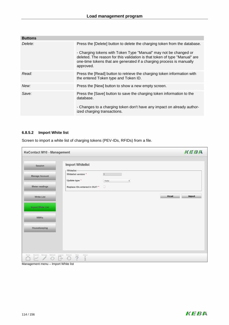
Load management program
114 / 156
Buttons
Delete: Press the [Delete] button to delete the charging token from the database. - Charging tokens with Token Type "Manual" may not be changed or deleted. The reason for this validation is that token of type "Manual" are one-time tokens that are generated if a charging process is manually approved.
Read: Press the [Read] button to retrieve the charging token information with the entered Token type and Token ID.
New: Press the [New] button to show a new empty screen.
Save: Press the [Save] button to save the charging token information to the database. - Changes to a charging token don't have any impact on already author-ized charging transactions.
6.8.5.2 Import White list
Screen to import a white list of charging tokens (PEV-IDs, RFIDs) from a file.
Management menu – Import White list

Load management program
115 / 156
White list
White list version:
Version number of the white list.
- The white list version entered into this text field and the white list version in the database must match.
Update type:
Indicates how the white list file will be applied.
Display Values:
Full: Charging tokens in the database that are not contained in the import file will be deleted (Replace IDs entered at the GUI=disabled re-quired).
Partial: Charging tokens in the database are not deleted when importing of a new white list file.
Imported only Only the charging tokens in the import file will be synchronized with the whitelist tokens that have been imported previously. The charging tokens entered at the GUI will not be considered.
Replace IDs entered at the GUI?
Charging tokens in the import file that are already contained in the data-base will be overwritten (checkbox enabled), otherwise ignored.
Buttons
Import: Press the [Import] button to select a file for upload. - Charging tokens in the import file that are not yet contained in the data-base will be imported. - The import doesn't affect charging tokens with the Token Type="Manual", they will neither be overwritten nor deleted. - If the white list version in the import file has already been imported, the import will be rejected. - The charging tokens inside the file must have a valid Token Type. To-ken Type "Manual" is not allowed.
Typical workflow: Import White list items
► Press the [Management] button in the toolbar. The Management screen (Charging Session Management) appears.
► Click at the button [White list] in the menu bar. The white list management screen appears.
► Press the [Import] button. The white list import screens appears.
► Enter the parameters required for the upload and press the [Import] button. A dialogue box appears that allows the selection of a file for upload to the KeContact M10.
► Return to the home screen by clicking on the [HOME] button .

Load management program
116 / 156
Structure of the White list import file: The White list import file is a comma-separated (*.csv) file. Each line has the following syntax:
[Token Type], [Token ID], [Status], [Expire Date]
RFID PEVID Manual Host
ID number
ACCEPTED BLOCKED EXPIRED INVALID PENDING
DD-MM-YYYY hh:mm:ss
File example:

Load management program
117 / 156
6.8.6 Manage NMKs
Screen to manage NMKs. Shows NMKs of all Wallboxes and allows distributing the NMKs to the Wallboxes. With Public NMKs you are able to connect to devices in the whole network supported with PLC modems in the Wallboxes. Private NMKs are useful to connect to one device specified in the network. The table shows which NMK is currently being used by which modem. If the Wallbox is offline, the last known status will be shown.
Management menu – Manage NMKs
NMKs in Wallboxes table
Wallbox: The socket ID of the Wallbox into which the modem has been integrated.
MAC address:
MAC address of the integrated modem. Please use the standard format for MAC addresses.
NMK: NMK currently stored in the modem (shown in hexadecimal notation).
If a Wallbox contains the public NMK, both NMK and password will be shown. If a Wallbox contains the private NMK, at least the information that have been entered by the user during the configuration of the NMK will be shown.
NMK password:
Network password of the integrated PLC modem (Wallbox). Might be empty, if NMK of the modem is not empty.
Date inquired:
Timestamp when the NMK in the Wallbox has been inquired for the last time.

Load management program
118 / 156
Charge Point NMK details
Uses public NMK? Indicates whether the Charge Point uses the public NMK or the private NMK for the communication with the Wallboxes.
Public network password PLC:
Network password associated with the public NMK for the PLC modem generated by the Charge Point. Is the same for all Wallboxes connected to a Charge Point. Might be empty if the “Public NMK” is not empty.
Public NMK: Public NMK for the PLC modem of the Wallbox. It is the same for all in-stallations and Wallboxes attached to them. Might be empty if the “Public network password PLC” is not empty.
Private network password PLC:
Network password associated with the private NMK for the PLC modem generated by the Charge Point. Is the same for all Wallboxes connected to a Charge Point. Might be empty if the “Private NMK” is not empty.
Private NMK:
Private NMK for the PLC modem generated by the Charge Point. Is the same for all Wallboxes connected to a Charge Point. Might be empty if the “Private network password PLC” is not empty.
Buttons
Set: Press the [Set] button to store the configuration settings for the NMK (public or private NMK; value of the private NMK will be stored). - The public NMK and the associated password are part of the configura-tion of the KeContact M10 system and can only be changed by a soft-ware update.
Typical workflow: Managing NMKs
► Press the [Management] button in the toolbar. The Management screen (Charging Session Management) appears.
► Click at the button [Manage NMKs] in the menu bar at the left side of the screen. The NMK Man-agement screen appears.
► Make the required changes and click at the [Set] button. The NMK settings can only be changed for the system as a whole. Changes will be transferred to the Wallboxes. If a Wallbox is busy or offline (not connected to the Charge Point), the changes will be transferred to the Wallboxes at a later point in time.
► The table showing the NMK state reflect the actual NMK settings reported by the Wallbox. The data shown in this table will not be refreshed. Up to date information can be loaded by clicking on the [Refresh] button in the toolbar.
► Return to the home screen by clicking on the [HOME] button .

Load management program
119 / 156
6.8.7 Housekeeping
Screens to start the housekeeping process and to manage the housekeeping parameters.
6.8.7.1 Start housekeeping
Screen to show the current resource usage and for starting the housekeeping process. Housekeeping runs automatically. The amount of data to be deleted is defined in a set of parameters which can be entered at the GUI of the KeContact M10. In addition to the automatic housekeeping it is also possi-ble to start housekeeping manually.
The disk space of the CF card is very limited. It is important to configure the housekeeping pa-rameters depending on the expected traffic of your system. The housekeeping process runs once a day and deletes log files or archives according to your configuration. In the first time it is rec-ommended to check the Free disk space periodically and if necessary, change the parameters accordingly.
Management menu – Start Housekeeping
Disk Space
Disk size: Size of the disk (in MB).
Free space: Free disk space (in MB).
Database size: Disk space (in MB) occupied by the database.

Load management program
120 / 156
Disk Usage
Firmware versions: Disk space occupied by firmware version packages (in MB).
Log files: Disk space occupied by log files download packages (in MB).
Metering archives: Disk space occupied by metering archives (in MB).
Software versions: Disk space occupied by software version packages (in MB).
Housekeeping jobs
Most recent housekeeping: Timestamp of the most recent housekeeping run.
Buttons:
Start: Press the [Start] button to start the housekeeping process immediately. The standard housekeeping parameters will be used. To selectively delete software versions, firmware versions, meter value archives, log files archives and diagnostics archives, the screens to man-age those artefacts can be used.
Typical workflow: Starting the housekeeping process manually
► Press the [Management] button in the toolbar. The Management screen (Charging Session Management) appears.
► Press the menu button [Housekeeping] at the left side of the screen. The housekeeping screen appears. Review the current state of the disk usage at the KeContact M10.
► If required, go to the tab [Housekeeping Parameters] to change the parameters for the house-keeping run. Change the parameters for the housekeeping run and press “Save”. Go back to tab “Start Housekeeping”.
► Start the housekeeping process by pressing the [Start] button. The housekeeping process runs in the background and might need a longer time. There is no immediate feedback.
► Return to the home screen by clicking on the [HOME] button .

Load management program
121 / 156
6.8.7.2 Housekeeping parameters
Screen to configure the housekeeping parameters.
Management menu – Housekeeping parameters
History
Transaction history: Maximum number of days the history of charging sessions and charging transactions shall be kept at the KeContact M10.
[default value: 60]
Meter values: Maximum number of days the meter values shall be kept at the KeCon-tact M10.
[default value: 7]

Load management program
122 / 156
Maximum number of archives
Diagnostic archives: Maximum number of archives containing diagnostics information that shall be kept at the disk of the KeContact M10.
[default value: 3]
Log file archives: Maximum number of archives containing log files that shall be kept at the disk of the KeContact M10.
[default value: 3]
Meter value archives: Maximum number of archives containing meter values that shall be kept at the disk of the KeContact M10.
[default value: 3]
Maximum number of versions
Firmware versions: Maximum number of firmware versions that shall be kept at the disk of the KeContact M10.
[default value: 3]
Software versions: Maximum number of software versions that shall be kept at the disk of the KeContact M10.
[default value: 3]
Typical workflow: Configure automated housekeeping processes
► Press the [Management] button in the toolbar. The Management screen (Charging Session Management) appears.
► Press the menu button [Housekeeping] at the left side of the screen. The housekeeping screen appears. Review the current state of the disk usage at the KeContact M10.
► Go to the tab [Housekeeping Parameters] to change the parameters for the housekeeping run. Change the parameters for the housekeeping run and press “Save”.
► Return to the home screen by clicking on the [HOME] button .

Load management program
123 / 156
6.9 Service menu
Press the [Service] button to show the “Service menu”.
Overview menu to support the service technician with diagnosing or updating of a KeCon-tact M10 system.
Service menu
The service menu of the KeContact M10 contains some administration functions that are not required fre-quently such as software updates or the exchange of digital certificates.
Manage Software Versions: A new version of the KeContact M10 software can be uploaded and in-stalled.
Manage Firmware Versions: A new version of the firmware for the Wallboxes connected with the Ke-Contact M10 can be uploaded and installed.
Handle Fault Reporting: If an error is detected, information that will help to diagnose and correct the fault can be downloaded.
Manage Certificates: Digital certificates to secure ISO/IEC 15118 communication, the communication to central systems using OCPP and Web communication for the user interface of the KeContact M10 can be uploaded and installed.
Manage Central System Interfaces: Interfaces to central systems can be installed and configured.

Load management program
124 / 156
6.9.1 Software Update
Screen to import and install software updates.
Service menu – Software update
Currently installed software version
Installed software version: Currently installed software version.
Time installed: Date and time at which the software version has been installed.
Software versions
Software version: Uploaded software version. The table contains all software version pack-ages that have been previously uploaded.
Date uploaded: Date and time at which the software version has been uploaded.

Load management program
125 / 156
Buttons
Delete: Press the [Delete] button to delete all selected software updates.
Upload: Press the [Upload] button to select a software update file for upload.
- The upload function will not trigger an automatic installation.
Install: Press the [Install] button to install the selected software version.
- Install is only possible, if only one software version has been selected.
Typical workflow: Manage Software versions Software update files for the KeContact M10 are “*.keb” files and can be uploaded and installed via the graphical user interface. The software version comes as an archive that should be stored onto a USB flash drive or other storage device that is accessible from the PC running the KeContact M10 user interface.
► Press the [Service] button in the toolbar at the bottom of the screen.
► Press the menu button [Software Update] at the left side of the screen. The software update screen appears. Review the installed and updated software versions to ensure that the installa-tion of the software version can work smoothly.
► Press the [Upload] button. A dialogue appears where the location of the archive with the new software version can be entered.
► When the upload is finished, select the software version to be installed and press [Install]. Installation will happen in the background and might take several minutes. The KeContact M10 will be restarted during this process.
► After the software update, return to the “Software Update” screen and review the software version information at the top of the screen to ensure that the update has worked.
► Return to the home screen by clicking on the [HOME] button .
When updating the KeContact M10 software, your personal settings are stored and therefore a new configuration of the system is not necessary. If there are problems with a new software version, a fallback to a previous version is possible by selecting the old version in the “Software Update” screen and pressing the “Install” button. Update files can be found in the download section at www.kecontact.com .

Load management program
126 / 156
6.9.2 Firmware Update
Screen to import and install firmware updates for the Wallboxes attached to the KeContact M10.
Service menu – Firmware update
Currently installed firmware version
Installed firmware version: The firmware version that is currently installed at the KeContact M10.
Time installed: The date and time at which the currently installed firmware version has been installed at the KeContact M10.
Firmware versions
Firmware version: A firmware version for which a package is available at the KeContact M10. The table contains all firmware version packages that have been previ-ously uploaded.
Date uploaded: The date and time at which the firmware version has been uploaded to the KeContact M10.

Load management program
127 / 156
Buttons
Delete: Press the [Delete] button to delete the selected firmware update.
Upload: Press the [Upload] button to select a firmware update file for upload.
- The upload function will not trigger an automatic installation.
Install: Press the [Install] button to install the selected firmware version.
- Install is only possible, if one and only firmware version has been se-lected.
Typical workflow: Manage Firmware versions Firmware update files for the KeContact P20 Wallboxes can be uploaded and installed via the graphical user interface. The firmware version comes as an archive that should be stored onto a USB flash drive or other storage device that is accessible from the PC running the KeContact M10 user interface.
► Press the [Service] button in the toolbar at the bottom of the screen.
► Press the menu button [Firmware Update] at the left side of the screen. The firmware update screen appears. Review the installed and updated firmware versions to ensure that the installa-tion of the software version can work smoothly.
► Press the [Upload] button. A dialogue appears where the location of the archive with the new firmware version can be entered.
► When the upload is finished, select the firmware version to be installed and press [Install].
Installation will happen in the background and might take several minutes. The Wallboxes will be restarted during this process. This also means that any charging sessions controlled using the PWM (Mode 3) signal will be terminated. If a Wallbox is offline during the update, the new firm-ware version will be installed as soon as the Wallbox comes online again.
► Return to the home screen by clicking on the [HOME] button . Wait until the Wallbox icons show that the Wallboxes are online again.
► Press the [Service] button in the toolbar at the bottom of the screen. The diagnostics in-formation screen appears.
► Press the menu button [Firmware Versions] at the left side of the screen. The firmware version screen appears. Review the listing of firmware versions per Wallbox installed to assure that the firmware update has worked properly.
► Return to the home screen by clicking on the [HOME] button .
If there are problems with a new firmware version, a fallback to a previous version is possible by selecting the old version in the “Firmware Update” screen and pressing the “Install” button. Update files can be found in the download section at www.kecontact.com .

Load management program
128 / 156
6.9.3 Firmware versions
Screen providing an overview of the current firmware versions installed at the KeContact M10
Service menu – Firmware versions
Currently installed at the charge point
Installed firmware version: The firmware version that is currently installed at the KeContact M10.
Time installed: The date and time at which the currently installed firmware version has been installed at the KeContact M10.
Firmware versions
Wallbox: Socket number of the Wallbox.
Firmware version: Firmware version of the Wallbox.
Date installed: Date and time of the installation of the firmware version at the Wallbox. This is the timestamp when the firmware version has been reported by the Wallbox to the KeContact M10 for the first time.

Load management program
129 / 156
6.9.4 Logfiles
Exports the logs to a file (either on an USB stick or a directory on the workstation).
Service menu – Log files
Log level
Log level: Level of detail for the log file to be created. Only valid for new log files.
Values:
Debug, Info, Warnings, Errors
Duration: Duration for which the change of the log level is valid (in minutes). When the duration has passed, the log level will return to the default settings.
Log file archives
Time created: Creation timestamp of a log file archive (local time).
Size (MB): Size of a log file archive (in MB).

Load management program
130 / 156
Buttons
Delete: Press the [Delete] button, to delete the selected log file archives.
Download: Press the [Download] button, to download the selected log file archives.
- A dialogue box will be presented that allows the user to select the loca-tion to which the files will be downloaded.
New: Press the [New] button, to generate a new logfile archive.
- All currently available logs will be collected and packaged into a new zip-archive. The archive will be shown at the archive table at this screen and is available for download.
Log files packed in a zip file are intended to use by service technicians and developers only and can be downloaded in the “Service menu – Log files” screen.
In case of unexpected errors, please send these files to the customer support with your service request.
Typical workflow: Generating Log files If an error is observed at the KeContact M10 that cannot be resolved without help, the support engineer asks for additional information about the KeContact M10 internals (log files or diagnostics information or both).
► Press the [Service] button in the toolbar at the bottom of the screen.
► If the support engineer has asked for log files, press the menu button [Log Files] at the left side of the screen. The log file screen appears.
► Generate a new log file archive by pressing the [New] button. The generation of the archive will take some time. When the archive has been generated, select it and press the [Download] button. A dialogue box appears where a storage location for the archive can be entered. This location must be accessi-ble from the PC of the operator using the Web interface of the KeContact M10.
► Return to the home screen by clicking on the [HOME] button .

Load management program
131 / 156
6.9.5 Diagnostics information
Screen to create and export diagnostics information to a zip file.
Service menu – Diagnostics Information
Buttons
Delete: Press the [Delete] button, to delete the selected diagnostics files ar-chives.
Download: Press the [Download] button, to download the selected diagnostics file archive.
New: Press the [New] button, to generate a new diagnostics file archive.
Diagnostic files packed in a zip file are intended to use by service technicians and developers only and can be downloaded in the “Service menu – Diagnostics” screen.
In case of unexpected errors, please send these files to the customer support with your service request.

Load management program
132 / 156
Typical workflow: Generating Diagnostics information If an error is observed at the KeContact M10 that cannot be resolved without help, the support engineer asks for additional information about the KeContact M10 internals (log files or diagnostics information or both).
► Press the [Service] button in the toolbar at the bottom of the screen.
► If the support engineer has asked for diagnostics information, press the menu button [Diagnos-tics] at the left side of the screen. The diagnostics screen appears.
► Generate a new diagnostics information archive by pressing the [New] button. The generation of the archive will take some time.
When the archive has been generated, select it and press the [Download] button. A dialogue box appears where a storage location for the archive can be entered. This location must be accessi-ble from the PC of the operator using the Web interface of the KeContact M10.
► Return to the home screen by clicking on the [HOME] button .
6.9.6 Digital Certificates
Screen to provide an overview of all previously uploaded digital certificates.
Service menu – Digital Certificates

Load management program
133 / 156
Certificates table
Alias: Readable name that can be used to identify the certificate.
Purpose: Purpose of the certificate. It is currently assumed that a particular certifi-cate only serves for one purpose (ISO 15118, OCPP Client, OCPP Serv-er or Web GUI).
Interface type: Type of the interface.
Serial number: Serial number of the certificate.
Status: Status of the certificate.
Display values:
Uploaded (the certificate has been uploaded, but not yet installed into the key store).
Installed (the certificate is available in the key store)
Expired (the certificate is expired)
Error (The certificate has been uploaded and the last attempt to in-stall the certificate has failed).
Expiry date: Expiration date of the digital certificate.
Buttons
Delete: Press the [Delete] button, to delete the selected certificate.
If the certificate is installed or expired, it will also be removed from the key store.
Install: Press the [Install] button, to provision the selected certificate to the key store.
- Install is only possible, if the certificate has the status “Uploaded”.
Manage: Press the [Manage] button, to view or change details of the selected cer-tificate.
Upload: Press the [Upload] button, to upload a new certificate.
- A dialogue box appears that allows the user to specify a location for the file to be uploaded from. The upload function will not trigger an automatic installation of the certificate.

Load management program
134 / 156
General description of a certificate file A certificate file is a “*.pfx” file and can be bought in various internet shops (e.g. http://www.digicert.com ). Certificate files can be uploaded via the graphical user interface (see “Service menu – Upload Certificate”). Contents of a certificate:
Country Name (2 letter code) [AU]: DE
State or Province Name (full name) [Some-State]: Bayern
Locality Name (eg, city) []: Ingolstadt
Organization Name (eg, company) [Internet Widgits Pty Ltd]: Unternehmen GmbH
Organizational Unit Name (eg, section) []:
Common Name (eg, YOUR name) []:
Email Address []: [email protected]
Security warning Like the pre-installed certificate, you can create your own non-verified certificate but your internet browser will show a security warning.
Typical workflow: Manage Certificates
► Press the [Service] button in the toolbar at the bottom of the screen.
► Press the menu button [Digital Certificates] at the left side of the screen. The digital certificates overview screen appears.
► Press the [Upload] button to upload the PFX file. The “Upload Certificate” screen appears.
► Enter the information about the intended usage of the certificate and press [Upload]. A dialogue box appears where the location of the pfx file can be entered. The PFX file must be accessible from the PC of the operator using the Web interface. After the upload, the “Certificate Overview” screen will be shown again.
► Select the certificate to be installed and press [Install]. A dialogue box appears where the pass-word for the PFX file must be entered.
The installation of the certificate happens in the background. After the process is completed, a status change is visible in the “Certificates Overview” screen. Because most the data shown in the screen are static, data shown in this screen will not be refreshed. Up to date information can be loaded by clicking on the [Refresh] button in the button bar at the bottom of the screen.
► Return to the home screen by clicking on the [HOME] button .

Load management program
135 / 156
6.9.7 Manage Certificates
Screen to view a server certificate and to update the purpose of the certificate. The KeContact M10 ships with an initial set of digital certificates.
Service menu – Manage certificate
Identification
Certificate ID: ID of the certificate issued by the KeContact M10.
Alias: Readable name that can be used to identify the certificate.

Load management program
136 / 156
Usage and status
Usage: Usage of the certificate. It is currently assumed that a particular certificate only serves for one purpose.
Display Values:
ISO 15118: Certificate is used as server certificate in the conversation with an electric vehicle using ISO 15118-2 CD.
OCPP Client: This certificate is used as client certificate when sending OCPP mes-sages.
OCPP Server: This certificate is used as server certificate when receiving OCPP messages.
Web GUI: This certificate is used by an https setup for the Web GUI of a Ke-Contact server instance.
Host Interface Type: Type of the interface for which the certificate can be used for secure communication.
Display values:
System Management The interface is used for monitoring, managing and configuring the KeContact server.
Energy Management The interface is used to manage the energy offered by the charge point. An example is a DSO interface using OCPP.
Full Management The interface is used for system management and energy manage-ment.
Status: Status of the certificate.
Display values:
Uploaded The certificate has been uploaded, but not yet installed into the key store.
Installed The certificate is available in the key store.
Expired The certificate is expired.
Error The certificate has been uploaded and the last attempt to install the certificate has failed.
Date uploaded: Date when the certificate has been uploaded to the KeContact M10.
Date installed: Timestamp when the digital certificate has been installed.

Load management program
137 / 156
Certificate details
Owner name: Name of the owner of the certificate.
Owner organisation: Organisation of the owner of the certificate.
Issuer name: Name of the issuer of the certificate.
Issuer organisation: Organisation of the issuer of the certificate.
Version: Version number of the certificate.
Serial number: Serial number of the certificate (up to 20 octets, represented as hexadec-imal numbers, with colons between the octets).
Date issued: Date when the certificate has been issued.
Date expired: Expiration date of the digital certificate.
Buttons
Install: Press the [Install] button to install the certificate shown at the screen.
Delete: Press the [Delete] button, to delete the certificate from the database.
If the certificate is installed or expired, it will also be removed from the key store.

Load management program
138 / 156
6.9.8 Upload Certificate
Screen to enter parameters for the upload of a new certificate.
Service menu – Upload Certificate
Certificate Purpose
Usage: Usage of the certificate. It is currently assumed that a particular certificate only serves for one purpose.
Display Values:
ISO 15118: Certificate is used as server certificate in the conversation with an electric vehicle using ISO 15118-2 CD.
OCPP Client: This certificate is used as client certificate when sending OCPP mes-sages.
OCPP Server: This certificate is used as server certificate when receiving OCPP messages.
Web GUI: This certificate is used by an https setup for the Web GUI of a Ke-Contact server instance.

Load management program
139 / 156
Host Interface Type: Type of the interface for which the certificate can be used for secure communication.
Display values:
System Management The interface is used for monitoring, managing and configuring the KeContact server.
Energy Management The interface is used to manage the energy offered by the charge point. An example is a DSO interface using OCPP.
Full Management The interface is used for system management and energy manage-ment.
Buttons
Upload: Press the [Upload] button, to select the location of the file (certificate). The upload function will not trigger an automatic installation of the certifi-cate.
6.9.9 OCPP Host Interfaces
Screen that provides an overview of the installed host interfaces and offers functions to start and stop the interfaces.
Service menu – OCPP interfaces

Load management program
140 / 156
Central System interfaces
Name: Name of the interface.
Type: Type of the interface.
Display values:
System Management The interface is used for monitoring, managing and configuring the KeContact server.
Energy Management The interface is used to manage the energy offered by the charge point. An example is a DSO interface using OCPP.
Energy and System Management The interface is used for system management and energy manage-ment.
Status: Status of the interface.
Display values:
Online The KeContact server is communicating with the central system using the OCPP interface.
Offline The host interface is working, but the central system is currently not reachable.
Stopped The interface to the central system has been temporarily deactivated.
Status Time: Time of the status change.
Buttons
Start: Press the [Start] button, to start a stopped host interface.
Stop: Press the [Stop] button, to stop the selected host interface.
Delete: Press the [Delete] button, to delete the selected host interface. Any message that has not been sent will be purged. The system might automatically restart to complete the deletion.
Change: Press the [Change] button, to change the parameters of the selected host interface.
Create: Press the [Create] button, to enter parameters for a new host interface.
Additional information: OCPP (“Open Charge Point Protocol”) is an interface between the KeContact M10 and an OCPP host. In-formation about the status, meter values, errors of the M10 and the connected Wallboxes will be provided if the interface is online.

Load management program
141 / 156
6.9.9.1 Configure Central system interface
This screen is for the configuration of general parameters of the Central system interface.
► To show this screen, select an item in the “OCPP interfaces” screen and press the [Change] button.
Configure OCPP Interface – Central system interface
Identification
Interface name: Identification name of the interface.

Load management program
142 / 156
Communication protocol
Central system name: Readable name of the host. Used for presentation at the user interface and in log files.
Communication protocol: Identifier of the Protocol:
Display values:
Full Management: Full set of OCPP messages including any proprietary extensions.
System Management: Set of currently supported OCPP messages that are useful for sys-tem management and remote management of charging transactions.
Energy Management: Set of OCPP messages including proprietary extensions based on forthcoming OCPP versions to integrate a KeContact Server into the network of a DSO or other energy management system for load management purposes.
Protocol version: Version of the protocol.
Display values:
1.5: OCPP 1.5 version with the priority extensions implemented to support the DSO interface and any configuration parameters handled by the OCPP messages GetConfiguration and ChangeConfiguration.
Interface type: Two host interfaces may not have the same interface type. If a host inter-face is of type “Full Management”, there may be no second host inter-face.
Display values:
System Management The interface is used for monitoring, managing and configuring the KeContact server.
Energy Management The interface is used to manage the energy offered by the charge point. An example is a DSO interface using OCPP.
Energy and System Management The interface is used for system management and energy manage-ment.
Status
Interface status: Status of the interface.
Display values:
Online The KeContact server is communicating with the central system using the OCPP interface.
Offline The host interface is working, but the central system is currently not reachable.
Stopped The interface to the central system has been temporarily deactivated.
Time last status change: Date and time of the last change of the Host interface status.

Load management program
143 / 156
General parameters
Use central system time: Indicates whether timestamps in messages sent via the Host Interface shall be in the time of the host (checkbox checked) or in local time at the KeContact server. The time will only be used in outgoing OCPP messag-es.
Store message when stopped?
Indicates whether messages addressed to the host will be stored (check-box checked) or dropped if the Host Interface is in state “Stopped”.
Message stored if offline for x minutes
Duration (in minutes) a message addressed to the host will be stored if the system has gone offline. Only if “Store message when stopped” is checked.
Authorize message support-ed?
Indicates whether the central system supports the Authorize message (checkbox checked).
Buttons
Save: Press the [Save] button, to store the configuration parameters of the cen-tral system interface. If the central interface does not yet exist, it will be created. Creating or changing of a Central system interface might lead to a restart of the ap-plication.
Typical workflow: Manage Central System Interfaces
► Set metering value collection policy as described in the workflow “Configure Meter Value Collec-tion”. If encrypted (SSL) communication is used, upload and install the necessary digital certifi-cates (see workflow “Manage Certificates”).
► Press the [Service] button in the toolbar at the bottom of the screen.
► Press the menu button [OCPP Interfaces] at the left side of the screen. The OCPP interfaces overview screen appears.
► Press the [Create] button to generate a new interface. The OCPP interface configuration screen appears.
► Enter the parameters of the OCPP interface into the configurations screens. Press the [Save] button to store the settings.
► Return to the home screen by clicking on the [HOME] button .

Load management program
144 / 156
6.9.9.2 Configure Central system interface - Communication
This screen is for the configuration of the communication between the charge point and the Central system.
Configure OCPP Interface - Central system interface Communication
Identification
Interface name: Identification name of the interface.
Addressing
Use TLS? Indicates whether the OCPP communication shall use HTTPS (checkbox checked) or HTTP (unchecked).
Address central system: The URL of the host (with the port) to be used for OCPP communication with that host.
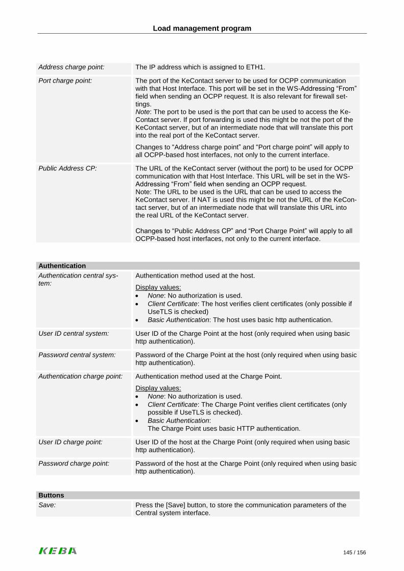
Load management program
145 / 156
Address charge point: The IP address which is assigned to ETH1.
Port charge point: The port of the KeContact server to be used for OCPP communication with that Host Interface. This port will be set in the WS-Addressing “From” field when sending an OCPP request. It is also relevant for firewall set-tings. Note: The port to be used is the port that can be used to access the Ke-Contact server. If port forwarding is used this might be not the port of the KeContact server, but of an intermediate node that will translate this port into the real port of the KeContact server.
Changes to “Address charge point” and “Port charge point” will apply to all OCPP-based host interfaces, not only to the current interface.
Public Address CP: The URL of the KeContact server (without the port) to be used for OCPP communication with that Host Interface. This URL will be set in the WS-Addressing “From” field when sending an OCPP request. Note: The URL to be used is the URL that can be used to access the KeContact server. If NAT is used this might be not the URL of the KeCon-tact server, but of an intermediate node that will translate this URL into the real URL of the KeContact server. Changes to “Public Address CP” and “Port Charge Point” will apply to all OCPP-based host interfaces, not only to the current interface.
Authentication
Authentication central sys-tem:
Authentication method used at the host.
Display values:
None: No authorization is used.
Client Certificate: The host verifies client certificates (only possible if UseTLS is checked)
Basic Authentication: The host uses basic http authentication.
User ID central system: User ID of the Charge Point at the host (only required when using basic http authentication).
Password central system: Password of the Charge Point at the host (only required when using basic http authentication).
Authentication charge point: Authentication method used at the Charge Point.
Display values:
None: No authorization is used.
Client Certificate: The Charge Point verifies client certificates (only possible if UseTLS is checked).
Basic Authentication: The Charge Point uses basic HTTP authentication.
User ID charge point: User ID of the host at the Charge Point (only required when using basic http authentication).
Password charge point: Password of the host at the Charge Point (only required when using basic http authentication).
Buttons
Save: Press the [Save] button, to store the communication parameters of the Central system interface.

Load management program
146 / 156
6.9.9.3 Configure Central system interface - Meter readings
This screen is for the configuration of the transfer of meter readings.
Configure OCPP Interface - Central system interface Meter Readings
Identification
Interface name: Identification name of the interface.
Meter reading transfer parameters
Send immediately? Send the Meter readings immediately after they have been collected (checkbox checked) or store until the current Meter value send interval has passed (unchecked).
Send every x seconds: Interval (in seconds) between sending of two sets of Meter readings using the Host Interface. The first interval starts at midnight.

Load management program
147 / 156
If no meter readings shall be sent at all, all attributes in the following group "Meter reading messages" must be set to false (checkboxes unchecked).
Meter reading messages
Send clock-aligned? Indicates whether to send Meter readings with Me-terReadingType=ClockAlignedCharge Point (checkbox checked).
Send clock-aligned per Wall-box?
Indicates whether to send Meter readings with Me-terReadingType=ClockAlignedSocket (checkbox checked).
Send session aligned?
Indicates whether to send Meter readings with Me-terReadingType=Transaction Aligned (checkbox checked).
Send at start of session?
Indicates whether to send Meter readings with Me-terReadingType=StartTransaction (checkbox checked).
Send at end of session?
Indicates whether to send Meter readings with Me-terReadingType=StopTransaction (checkbox checked).
Buttons
Save: Press the [Save] button, to store the meter reading parameters of the Central system interface.

Load management program
148 / 156
6.10 About screen
Press the [Information] button to show the “About” screen.
This screen shows details about the installation such as software and firmware versions and license information.
About screen
Charge Point
Model: Model name of the Charge Point (e.g. KeContact M10).
Installed software version: Currently installed software version. This is the overall software version including the operating system of the KeContact M10.
Installed firmware version: The firmware version that is currently installed at the KeContact M10.

Load management program
149 / 156
Copyright and legal information
Copyrights: Copyright - KEBA AG. All rights reserved.
Legal: Legal statements referring to the KeContact M10 in addition to the copy-right notice.
KEBA is the sole proprietor of the intellectual and industrial property rights of this software product. This software product is protected world-wide. All conceivable patent rights remain with KEBA. With delivery of this software product the user obtains the right to use the software product in combination with the delivered hardware (KeControl C3 - CP 332/M). Manipulation and copying is only allowed within the scope of council di-rective 91/250/ECC. Unauthorized use, copying and manipulation of the software product or parts of the software product is prohibited and will be prosecuted.
Please note: Reference to third party software that has been integrated into the Ke-Contact M10 software. KEBA AG is not responsible for these software components and is not liable for it.
6.11 Error screen
This screen is shown if a technical error occurs (HTTP error).
Error screen
HTTP Error
Error text: Text of the HTTP error message including the HTTP error code.
Error explanation: Explanation what the user shall do in case of an error.

Appendix
150 / 156
7 Appendix
7.1 Glossary
Charge Point is a technical system that can be used to charge one or more electric vehicles (one or more outlets).
M10 system is a charge point for fleets of electric vehicles consisting of hardware and software developed by KEBA AG and specified in this document.
High-Level Communication is used for the communication between charge point and electric vehicle based on ISO 15118 or a similar communication protocol.
KeContact LAN is the local area network that connects the charge points, electric vehicles and the KeCon-tact M10.
KeContact M10 is an industrial PC developed and marketed by KEBA AG. It is used as the central man-agement component (hardware and software).
MAC address is a unique identifier assigned to network interface components such as Ethernet cards.
Public LAN is the term used in this document for the local area network that connects the KeContact M10 with the public internet or the intranet of the organization that is operating the load management system.
Wallbox is the KeContact P20 charging station (with one outlet). The Wallbox sometimes is also called “Socket” in association with the M10.
7.2 List of Abbreviations
CP Control Pilot
DSO Distribution System Operator
EV Electric Vehicle
EVSE Electric Vehicle Supply Equipment
GP GreenPHY
GUI Graphical User Interface
LM Load Management
LMC Load Management Controller
NAT Network Address Translation
NEK Network Encryption Key
NMK Network Membership Key
OCPP Open Charge Point Protocol
PDC Power Distribution Controller
PLC Power Line Communication
PEV-ID Unique identifier of the Electric Vehicle
PWM Pulse Width Modulation
RFID Radio Frequency Identification
VNC Virtual Network Communication

Appendix
151 / 156
7.3 Data sheet power supply TDK-Lambda DPP50
Dimensions

Appendix
152 / 156

INDEX
153 / 156
8 INDEX
A
About screen ............................................................ 148
About this manual ........................................................ 7
Accessing the Load management program ................ 32
Addressing ................................................................. 19
Administrator-Account .............................................. 35
Appendix ................................................................. 150
B
Backup of the Compact Flash card ............................ 29
C
Change password ....................................................... 34
Charge Point configuration ........................................ 68
Common power line .................................................. 16
Configuration menu ................................................... 66
Edit Power Profile ................................................. 87
Power Profile configuration .................................. 83
View Power Profile ............................................... 91
Wallbox configuration ........................................... 79
Configuration-Account .............................................. 35
Corporate network ..................................................... 19
Current allocation on multiple vehicles ..................... 14
D
Description of a certificate file ................................ 134
DIP-switch settings .................................................... 20
Documentation for further reading .............................. 7
E
Error screen .............................................................. 149
Ethernet wiring .......................................................... 18
F
First time installation ................................................. 26
G
General statement ...................................................... 11
Glossary ................................................................... 150
H
Hardware installation ................................................. 16
Home screen .............................................................. 36
Home screen icons ..................................................... 37
I
Important information .................................................. 6
Installation menu ................................................. 27, 92
Installation-Account .................................................. 35
Intended audience for this manual ............................... 7
Intended use ................................................................. 6
K
KeContact M10 MMI menu ...................................... 24
KeContact P20 Wallbox .............................................. 9
L
List of Abbreviations ............................................... 150
Load management program ....................................... 30
Login .......................................................................... 33
M
Management menu ..................................................... 96
Charging session .................................................... 97
Charging session details ...................................... 100
Configure White list entry ................................... 112
Download meter readings .................................... 107
Housekeeping ...................................................... 119
Housekeeping parameters .................................... 121
Import White list .................................................. 114
Manage Accounts ................................................ 102
Manage NMKs .................................................... 117
Manage White list ................................................ 109
Select Account ..................................................... 104
Start housekeeping ............................................... 119
View Meter Readings .......................................... 105
Management-Account ................................................ 35
Meter readings file description ................................ 108
Monitoring menu ....................................................... 38
Charge Point Overview ......................................... 39
Power usage ........................................................... 65
Session history ....................................................... 63
Session overview ................................................... 60
Wallbox details ...................................................... 51
N
Numbering ................................................................. 19
O
Operating mode .......................................................... 66
P
Preconfigured Parameters tab .................................... 81
Provisions for flawless ISO 15118 communication ... 17
R
Rebooting the system ................................................. 37
S
Safety instructions ........................................................ 6
Scope of delivery ....................................................... 10
Service menu ............................................................ 123
Configure Central system interface ..................... 141
Configure Central system interface -
Communication ............................................... 144
Configure Central system interface - Meter readings
......................................................................... 146
Diagnostics information ...................................... 131
Digital Certificates ............................................... 132
Firmware Update ................................................. 126
Firmware versions ............................................... 128

INDEX
154 / 156
Logfiles ............................................................... 129
Manage Certificates ............................................. 135
OCPP Host Interfaces .......................................... 139
Software Update .................................................. 124
Upload certificate ................................................ 138
Software architecture ................................................. 15
Standard accounts and passwords .............................. 35
Supported communication protocols ......................... 12
System components ..................................................... 9
System configuration information ............................. 11
System Overview ......................................................... 8
T
Toolbar icons ............................................................. 31
U
Update installation ..................................................... 92
User-Accounts ........................................................... 35
V
Validity ........................................................................ 7
Value for limitation of the power grid ....................... 13
W
Wallbox numbering and Ethernet addressing ............ 19
Workflows
Authorize Charging Sessions ................................ 99
Change password ................................................... 35
Changing the Operating mode of a Charge Point .. 70
Changing the Operating mode of a Wallbox ......... 80
Configure automated housekeeping processes .... 122
Configure meter value collection ........................... 77
Configure power control ........................................ 78
Configuring Maximum Power ............................... 70
Enable/ Disable Authorization (Charge Point) ...... 75
Enable/ Disable Authorization (Wallbox) ............. 81
Export meter values ............................................. 108
Generating Diagnostics information .................... 132
Generating LogFiles ............................................ 130
Import White list items ........................................ 115
Manage accounts ................................................. 103
Manage Central System Interfaces ...................... 143
Manage Certificates ............................................. 134
Manage Charging Sessions .................................... 99
Manage Firmware versions ................................. 127
Manage power control ........................................... 78
Manage Software versions ................................... 125
Manage Whitelist items ....................................... 111
Managing NMKs ................................................. 118
Monitor Charging Sessions ................................... 62
Scheduling available Energy (existing Power
Profile) .............................................................. 90
Scheduling available energy (new Power Profile) . 86
Starting the housekeeping process manually ....... 120
Teaching vehicle IDs ........................................... 111
Using password protected screens ......................... 33
View meter values ............................................... 106
Viewing Charge Point details ................................ 41
Viewing Wallbox details ....................................... 53

____________________________________________________________________________________ ____________________________________________________________________________________ ____________________________________________________________________________________ ____________________________________________________________________________________ ____________________________________________________________________________________ ____________________________________________________________________________________ ____________________________________________________________________________________ ____________________________________________________________________________________ ____________________________________________________________________________________ ____________________________________________________________________________________ ____________________________________________________________________________________ ____________________________________________________________________________________ ____________________________________________________________________________________ ____________________________________________________________________________________ ____________________________________________________________________________________ ____________________________________________________________________________________ ____________________________________________________________________________________ ____________________________________________________________________________________ ____________________________________________________________________________________ ____________________________________________________________________________________ ____________________________________________________________________________________ ____________________________________________________________________________________ ____________________________________________________________________________________ ____________________________________________________________________________________ ____________________________________________________________________________________ ____________________________________________________________________________________ ____________________________________________________________________________________ ____________________________________________________________________________________ ____________________________________________________________________________________


![KeContact P20 Installation manual - The Mobility House€¦ · · 2016-05-30KEBA AG, Postfach 111, Gewerbepark Urfahr, ... KeContact P20 Use of this manual ... [S] is used for authorizing](https://static.fdocuments.net/doc/165x107/5ae548ed7f8b9a7b218f830a/kecontact-p20-installation-manual-the-mobility-house-2016-05-30keba-ag-postfach.jpg)


![(pentru specialist) Manual de instalare KeContact P20 / P30 · a unui utilizator cu carduri MIFARE sau tag-uri conform ISO14443. Comutator cu cheie Comutatorul cu cheie [S] serveşte](https://static.fdocuments.net/doc/165x107/5e4f383e7e8c041ea955ed6c/pentru-specialist-manual-de-instalare-kecontact-p20-a-unui-utilizator-cu-carduri.jpg)