
KCM Instructions Manual, German and English Instruction Manual... · Betriebsanleitung KCM...
80
S701x2-S724x2 Руководство по эксплуатации 1 KCM Usable with AKD, S300, S400, S600, S700 (400/480V, max. 48A) Deutsch Betriebsanleitung KCM Kondensatormodule English Instruction Manual KCM Capacitor Modules Original Language is German. All other content is translated from the original language. Edition 05/2016 Bewahren Sie das Handbuch als Produktbestandteil während der Lebensdauer des Produktes auf. Geben Sie das Handbuch an nachfolgende Benutzer oder Besitzer des Produktes weiter. Keep the manual as a product component during the life span of the product. Pass the manual to future users / owners of the product.
Transcript of KCM Instructions Manual, German and English Instruction Manual... · Betriebsanleitung KCM...
S701x2-S724x2 Руководство по эксплуатации 1
KCM Usable with AKD, S300, S400, S600, S700 (400/480V, max. 48A)
Deutsch Betriebsanleitung KCM Kondensatormodule English Instruction Manual KCM Capacitor Modules
Original Language is German. All other content is translated from the original language. Edition 05/2016
Bewahren Sie das Handbuch als Produktbestandteil während der Lebensdauer des Produktes auf. Geben Sie das Handbuch an nachfolgende Benutzer oder Besitzer des Produktes weiter. Keep the manual as a product component during the life span of the product. Pass the manual to future users / owners of the product.
Betriebsanleitung KCM Kondensatormodul / Instruction Manual KCM Capacitor ModulesV1.0DE/EN
UrheberrechteAlle Rechte vorbehalten.
Jede Vervielfältigung, Adaption oder Übersetzung ohne vorherige schriftliche Genehmigung
ist untersagt, außer im Rahmen des Urheberrechtsgesetzes.
© Copyright KOLLMORGEN Europe GmbH
CopyrightAll rights reserved.
Any duplication, adaptation or translation without prior written permission
is prohibited, unless it is under copyright law.
© Copyright KOLLMORGEN Europe GmbH
Technische Änderungen vorbehalten!Durch Weiterentwicklung des Produkts können die in dieser Betriebsanleitung verwendeten / angegebenen Abbildungen und Technische Daten geringfügig vom aktuellen Zustand abweichen.
We reserve the right to make technical changes.Due to the product's further development, the diagrams and
technical data used/indicated in this Betriebsanleitung may
be slightly different from the current status.
V1.0DE/EN
Betriebsanleitung KCM KondensatormoduleV1.0DE/EN i
Deutsch
Kollmorgen 05/2016 Inhaltsverzeichnis
1 Einführung1.1 Vorwort . . . . . . . . . . . . . . . . . . . . . . . . . . . . . . . . . . . . . . . . . . . . . . . . . . . . . . . . . . . . . . . . . . . 11.2 Umweltschutz . . . . . . . . . . . . . . . . . . . . . . . . . . . . . . . . . . . . . . . . . . . . . . . . . . . . . . . . . . . . . . 11.3 Umgang mit dieser Betriebsanleitung . . . . . . . . . . . . . . . . . . . . . . . . . . . . . . . . . . . . . . . . . . . . 11.3.1 Zielgruppe . . . . . . . . . . . . . . . . . . . . . . . . . . . . . . . . . . . . . . . . . . . . . . . . . . . . . . . . . . . . . . . . . 11.3.2 Grundsätzliches. . . . . . . . . . . . . . . . . . . . . . . . . . . . . . . . . . . . . . . . . . . . . . . . . . . . . . . . . . . . . 21.3.3 Abkürzungen . . . . . . . . . . . . . . . . . . . . . . . . . . . . . . . . . . . . . . . . . . . . . . . . . . . . . . . . . . . . . . . 21.3.4 Textauszeichnungen . . . . . . . . . . . . . . . . . . . . . . . . . . . . . . . . . . . . . . . . . . . . . . . . . . . . . . . . . 31.3.5 Definitionen . . . . . . . . . . . . . . . . . . . . . . . . . . . . . . . . . . . . . . . . . . . . . . . . . . . . . . . . . . . . . . . . 3
2 Gerätebeschreibung2.1 Bestimmungsgemäße Verwendung . . . . . . . . . . . . . . . . . . . . . . . . . . . . . . . . . . . . . . . . . . . . . 52.2 Angewandte Richtlinien . . . . . . . . . . . . . . . . . . . . . . . . . . . . . . . . . . . . . . . . . . . . . . . . . . . . . . . 52.3 Typenschlüssel . . . . . . . . . . . . . . . . . . . . . . . . . . . . . . . . . . . . . . . . . . . . . . . . . . . . . . . . . . . . . 62.4 Übersichtsbild . . . . . . . . . . . . . . . . . . . . . . . . . . . . . . . . . . . . . . . . . . . . . . . . . . . . . . . . . . . . . . 72.5 Typenschilder . . . . . . . . . . . . . . . . . . . . . . . . . . . . . . . . . . . . . . . . . . . . . . . . . . . . . . . . . . . . . . 82.6 Kennzeichnungen auf dem Gehäuse . . . . . . . . . . . . . . . . . . . . . . . . . . . . . . . . . . . . . . . . . . . . 92.7 Umgebungsbedingungen . . . . . . . . . . . . . . . . . . . . . . . . . . . . . . . . . . . . . . . . . . . . . . . . . . . . 102.8 Elektrische Anschlusswerte. . . . . . . . . . . . . . . . . . . . . . . . . . . . . . . . . . . . . . . . . . . . . . . . . . . 102.9 Abmessungen und Gewicht. . . . . . . . . . . . . . . . . . . . . . . . . . . . . . . . . . . . . . . . . . . . . . . . . . . 102.10 Lärmemission . . . . . . . . . . . . . . . . . . . . . . . . . . . . . . . . . . . . . . . . . . . . . . . . . . . . . . . . . . . . . 10
3 Grundlegende Sicherheitshinweise3.1 Personal . . . . . . . . . . . . . . . . . . . . . . . . . . . . . . . . . . . . . . . . . . . . . . . . . . . . . . . . . . . . . . . . . 113.2 Gerät . . . . . . . . . . . . . . . . . . . . . . . . . . . . . . . . . . . . . . . . . . . . . . . . . . . . . . . . . . . . . . . . . . . . 113.3 Anforderungen Underwriters Laboratories (UL) . . . . . . . . . . . . . . . . . . . . . . . . . . . . . . . . . . . 12
4 Transport / Lagerung / Montage4.1 Lieferung prüfen . . . . . . . . . . . . . . . . . . . . . . . . . . . . . . . . . . . . . . . . . . . . . . . . . . . . . . . . . . . 134.2 KCM Kondensatormodul transportieren . . . . . . . . . . . . . . . . . . . . . . . . . . . . . . . . . . . . . . . . . 134.3 KCM Kondensatormodul lagern . . . . . . . . . . . . . . . . . . . . . . . . . . . . . . . . . . . . . . . . . . . . . . . 134.4 KCM Kondensatormodul auspacken . . . . . . . . . . . . . . . . . . . . . . . . . . . . . . . . . . . . . . . . . . . . 134.5 KCM Kondensatormodul montieren . . . . . . . . . . . . . . . . . . . . . . . . . . . . . . . . . . . . . . . . . . . . 144.6 KCM Kondensatormodul erden . . . . . . . . . . . . . . . . . . . . . . . . . . . . . . . . . . . . . . . . . . . . . . . . 15
5 Inbetriebnahme5.1 KCM Kondensatormodul anschließen . . . . . . . . . . . . . . . . . . . . . . . . . . . . . . . . . . . . . . . . . . . 165.1.1 KCM-S anschließen. . . . . . . . . . . . . . . . . . . . . . . . . . . . . . . . . . . . . . . . . . . . . . . . . . . . . . . . . 175.1.2 KCM-P anschließen. . . . . . . . . . . . . . . . . . . . . . . . . . . . . . . . . . . . . . . . . . . . . . . . . . . . . . . . . 205.2 Zwei oder mehr KCM Kondensatormodule parallel anschließen . . . . . . . . . . . . . . . . . . . . . . 215.3 Zwei oder mehr Applikationen mit einem Zwischenkreisverbund
an einem KCM Kondensatormodul anschließen . . . . . . . . . . . . . . . . . . . . . . . . . . . . . . . . . . . 225.4 RS422-Kommunikationsschnittstelle anschließen. . . . . . . . . . . . . . . . . . . . . . . . . . . . . . . . . . 235.5 Überwachungsschnittstelle anschließen (geräteabhängig) . . . . . . . . . . . . . . . . . . . . . . . . . . . 245.6 KCM Kondensatormodul trennen . . . . . . . . . . . . . . . . . . . . . . . . . . . . . . . . . . . . . . . . . . . . . . 275.7 KCM Kondensatormodul formieren . . . . . . . . . . . . . . . . . . . . . . . . . . . . . . . . . . . . . . . . . . . . . 28
6 Sonstige Tätigkeiten6.1 KCM Kondensatormodul reinigen . . . . . . . . . . . . . . . . . . . . . . . . . . . . . . . . . . . . . . . . . . . . . . 296.2 KCM Kondensatormodul warten . . . . . . . . . . . . . . . . . . . . . . . . . . . . . . . . . . . . . . . . . . . . . . . 296.3 KCM Kondensatormodul reparieren . . . . . . . . . . . . . . . . . . . . . . . . . . . . . . . . . . . . . . . . . . . . 306.4 KCM Kondensatormodul entsorgen . . . . . . . . . . . . . . . . . . . . . . . . . . . . . . . . . . . . . . . . . . . . 30

Betriebsanleitung KCM KondensatormoduleV1.0DE/ENii
Inhaltsverzeichnis 05/2016 Kollmorgen
Deutsch
7 Erweiterungsmodul7.1 Technische Daten. . . . . . . . . . . . . . . . . . . . . . . . . . . . . . . . . . . . . . . . . . . . . . . . . . . . . . . . . . . 317.2 Transport / Lagerung / Montage . . . . . . . . . . . . . . . . . . . . . . . . . . . . . . . . . . . . . . . . . . . . . . . . 317.3 Ein Erweiterungsmodul an das KCM Kondensatormodul anschließen . . . . . . . . . . . . . . . . . . 317.4 Ein weiteres Erweiterungsmodul anschließen . . . . . . . . . . . . . . . . . . . . . . . . . . . . . . . . . . . . . 347.5 Erweiterungsmodul trennen . . . . . . . . . . . . . . . . . . . . . . . . . . . . . . . . . . . . . . . . . . . . . . . . . . . 357.6 Sonstige Tätigkeiten . . . . . . . . . . . . . . . . . . . . . . . . . . . . . . . . . . . . . . . . . . . . . . . . . . . . . . . . . 35
Betriebsanleitung KCM KondensatormoduleV1.0DE/EN 1
Deutsch
Kollmorgen 05/2016 1 Einführung
1 EINFÜHRUNG
1.1 VorwortSie haben sich für die zukunftweisende Energietechnologie der KOLLMORGEN
Europe GmbH entschieden.
Wir danken Ihnen für das entgegengebrachte Vertrauen.
Mit innovativen Produkten setzen wir als Systemanbieter verlässliche Standards in
der Energietechnologie. Mit der Zertifizierung unseres Umweltmanagements nach
EMAS III sowie unseres Qualitätsmanagements nach DIN EN ISO 9001 bekennen
wir uns zu einer nachhaltigen Unternehmenskultur.
1.2 Umweltschutz
Verpackungen Verpackungen bestehen aus umweltgerechten Materialien und können über die
örtliche Müllentsorgung entsorgt werden.
Geräte Die KOLLMORGEN Europe GmbH nimmt defekte oder nicht mehr verwendete
Geräte zurück.
1.3 Umgang mit dieser Betriebsanleitung
1.3.1 ZielgruppeDiese Betriebsanleitung richtet sich an qualifiziertes Elektrofachpersonal, das mit
dem KCM Kondensatormodul der KOLLMORGEN Europe GmbH in allen Lebens-
zyklen umgehen soll.
Dazu gehören:
• KCM-S: Spart Energie
• KCM-P: Power trotz Netzausfall
• KCM-E: Erweiterungsmodul
Betriebsanleitung KCM KondensatormoduleV1.0DE/EN2
Deutsch
1 Einführung 05/2016 Kollmorgen
1.3.2 GrundsätzlichesDie Betriebsanleitung ist in einzelne Kapitel unterteilt.
Beachten Sie Folgendes:
• Lesen Sie vor dem ersten Gebrauch des KCM Kondensatormoduls diese Be-
triebsanleitung sorgfältig und vollständig durch. Während des Gebrauchs ist es
dafür zu spät!
• Bemühen Sie sich, sie zu verstehen. Erst danach sind Sie in der Lage, das KCM
Kondensatormodul sicher und bestimmungsgemäß zu betreiben.
• Handeln Sie stets entsprechend den in der Betriebsanleitung gegebenen
Anweisungen.
• Bewahren Sie diese Betriebsanleitung in Gerätenähe auf.
Der Ablageort muss bekannt sein.
1.3.3 Abkürzungen
BGV Berufsgenossenschaftliche VorschriftEEPROM Electrical Eraseable Programmable Read Only Memory
Elektrisch löschbarer programmierbarer Speicher (-baustein)EMV Elektromagnetische VerträglichkeitEN Europäische NormEU Europäische UnionIT Isolated Terra (isoliertes Netz)KCM-E KOLLMORGEN Capacitor Module - ErweiterungsmodulKCM-P KOLLMORGEN Capacitor Module - EnergieversorgungKCM-S KOLLMORGEN Capacitor Module - EnergiespeicherLED Leuchtdiode (light-emitting diode)RFC Resonanz Frequenz CorrectionSPS Speicher-programmierbare SteuerungUL Underwriters Laboratories
(Unabhängige Organisation, die Produkte hinsichtlich ihrer Sicherheit untersucht und zertifiziert)
Betriebsanleitung KCM KondensatormoduleV1.0DE/EN 3
Deutsch
Kollmorgen 05/2016 1 Einführung
1.3.4 Textauszeichnungen
Verweis Ein Verweis auf andere Seiten in dieser Betriebsanleitung beginnt mit dem
Doppelpfeil-Symbol „ “.
Aktion und Reaktion Das Symbol „⌧“ kennzeichnet eine Aktion des Personals, während das
Symbol „ “ die ausgelöste Reaktion des Gerätes kennzeichnet.
Beispiel:
⌧Hauptschalter einschalten.
Lampe leuchtet.
Bildpositionen und
Bild-Text-Bezug
Wichtige Details werden in Grafiken mit Nummern (z. B. q) gekennzeichnet.
Im Text erfolgt der Bezug zu dieser Position durch diese Nummer hinter dem zuge-
hörigen Detail.
1.3.5 Definitionen
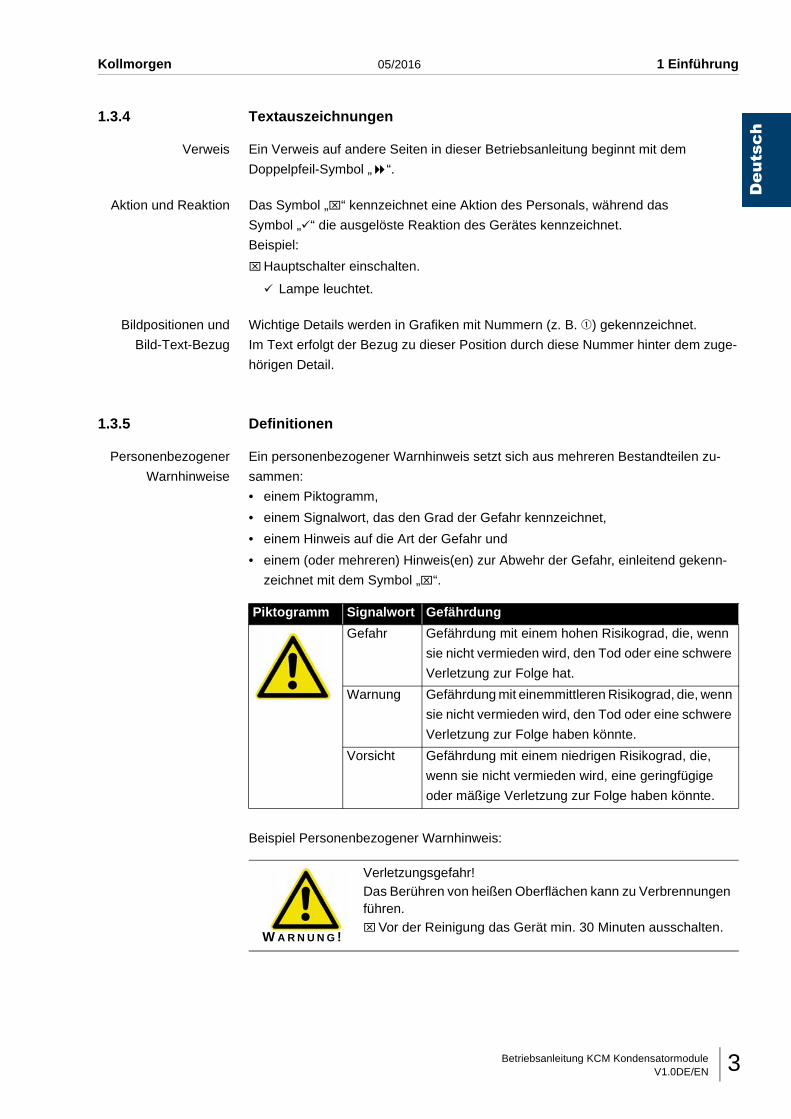
Personenbezogener
Warnhinweise
Ein personenbezogener Warnhinweis setzt sich aus mehreren Bestandteilen zu-
sammen:
• einem Piktogramm,
• einem Signalwort, das den Grad der Gefahr kennzeichnet,
• einem Hinweis auf die Art der Gefahr und
• einem (oder mehreren) Hinweis(en) zur Abwehr der Gefahr, einleitend gekenn-
zeichnet mit dem Symbol „⌧“.
Beispiel Personenbezogener Warnhinweis:
Piktogramm Signalwort Gefährdung
Gefahr Gefährdung mit einem hohen Risikograd, die, wenn
sie nicht vermieden wird, den Tod oder eine schwere
Verletzung zur Folge hat.
Warnung Gefährdung mit einemmittleren Risikograd, die, wenn
sie nicht vermieden wird, den Tod oder eine schwere
Verletzung zur Folge haben könnte.
Vorsicht Gefährdung mit einem niedrigen Risikograd, die,
wenn sie nicht vermieden wird, eine geringfügige
oder mäßige Verletzung zur Folge haben könnte.
W A R N U N G !
Verletzungsgefahr!Das Berühren von heißen Oberflächen kann zu Verbrennungen führen.⌧Vor der Reinigung das Gerät min. 30 Minuten ausschalten.
Betriebsanleitung KCM KondensatormoduleV1.0DE/EN4
Deutsch
1 Einführung 05/2016 Kollmorgen
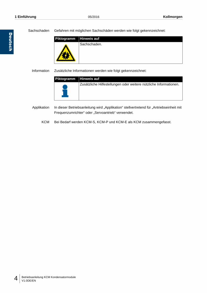
Sachschaden Gefahren mit möglichen Sachschäden werden wie folgt gekennzeichnet:
Information Zusätzliche Informationen werden wie folgt gekennzeichnet:
Applikation In dieser Betriebsanleitung wird „Applikation“ stellvertretend für „Antriebseinheit mit
Frequenzumrichter“ oder „Servoantrieb“ verwendet.
KCM Bei Bedarf werden KCM-S, KCM-P und KCM-E als KCM zusammengefasst.
Piktogramm Hinweis auf
Sachschaden.
Piktogramm Hinweis auf
Zusätzliche Hilfestellungen oder weitere nützliche Informationen.
Betriebsanleitung KCM KondensatormoduleV1.0DE/EN 5
Deutsch
Kollmorgen 05/2016 2 Gerätebeschreibung
2 GERÄTEBESCHREIBUNG
2.1 Bestimmungsgemäße Verwendung
KCM-S Dient zum Speichern von Bremsenergie von Applikationen (Antriebe mit Frequenz-
umrichter oder Servoantriebe). Das KCM-S benötigt keine eigene Spannungsversor-
gung. Es ist möglich, mehrere KCM-S parallel zu betreiben, um die maximale
Leistung zu vergrößern. Zur Energiespeichervergrößerung können auch optionale
Erweiterungsmodule (KCM-E) angeschlossen werden.
Das KCM-S wird kundenspezifisch ausgeliefert und darf nur unter Einhaltung dieser
Spezifikationen betrieben werden.
KCM-P Dient zur netzunabhängigen Versorgung eines Gleichstromzwischenkreises von
Applikationen (Frequenzumrichtern oder Servoantrieben) mit elektrischer Span-
nung. Das KCM-P benötigt keine eigene Spannungsversorgung. Es ist möglich,
mehrere KCM-P parallel zu betreiben, um die maximale Leistung zu vergrößern.
Zur Energiespeichervergrößerung können auch optionale Erweiterungsmodule
(KCM-M) angeschlossen werden.
Das KCM-P wird kundenspezifisch ausgeliefert und darf nur unter Einhaltung dieser
Spezifikationen betrieben werden.
KCM-E Wird an die KCM Kondensatormodule KCM-S oder KCM-P angeschlossen und ver-
größert deren Energiespeicher.
Werden mehrere dynamische KCM Kondensatormodule parallel angeschlossen,
sind die zusätzlichen KCM-E symmetrisch zu verteilen.
Schutzeinrichtung Schutzeinrichtungen (z. B. Abdeckung) dürfen nicht entfernt werden.
Einsatzbereich Der Einsatzbereich der KCM Kondensatormodule ist innerhalb von Elektroschalt-
schränken im Industriebereich. Der Betrieb in explosionsgefährdeten Bereichen ist
untersagt.
Umbauten Eigenmächtige Umbauten sind verboten.
Garantie- und Haftungsansprüche erlöschen dadurch.
Instandhaltung Instandhaltungsarbeiten dürfen nur vom Hersteller durchgeführt werden.
2.2 Angewandte RichtlinienDie KCM Kondensatormodule erfüllen die grundlegenden Anforderungen der Richt-
linie 2014/35/EU (Niederspannungsrichtlinie) und der Richtlinie 2014/30/EU (EMV-
Richtlinie).
Betriebsanleitung KCM KondensatormoduleV1.0DE/EN6
Deutsch
2 Gerätebeschreibung 05/2016 Kollmorgen
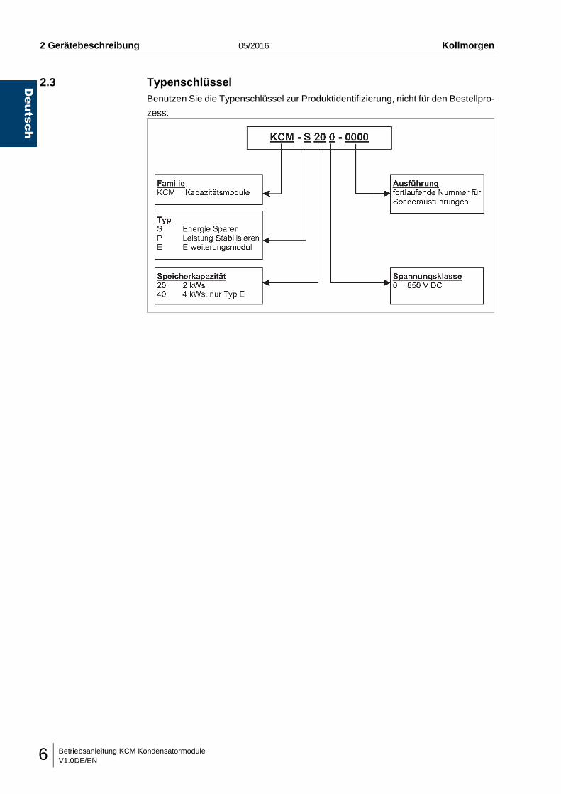
2.3 TypenschlüsselBenutzen Sie die Typenschlüssel zur Produktidentifizierung, nicht für den Bestellpro-
zess.
Betriebsanleitung KCM KondensatormoduleV1.0DE/EN 7
Deutsch
Kollmorgen 05/2016 2 Gerätebeschreibung
2.4 Übersichtsbild
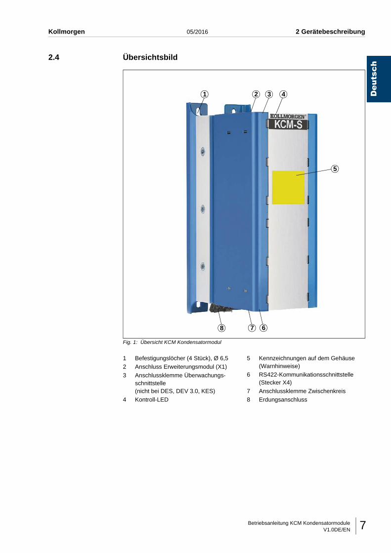
Fig. 1: Übersicht KCM Kondensatormodul
1 Befestigungslöcher (4 Stück), Ø 6,52 Anschluss Erweiterungsmodul (X1)
3 Anschlussklemme Überwachungs-schnittstelle (nicht bei DES, DEV 3.0, KES)
4 Kontroll-LED
5 Kennzeichnungen auf dem Gehäuse (Warnhinweise)
6 RS422-Kommunikationsschnittstelle (Stecker X4)
7 Anschlussklemme Zwischenkreis8 Erdungsanschluss
1 2 3 4
5
678
Betriebsanleitung KCM KondensatormoduleV1.0DE/EN8
Deutsch
2 Gerätebeschreibung 05/2016 Kollmorgen
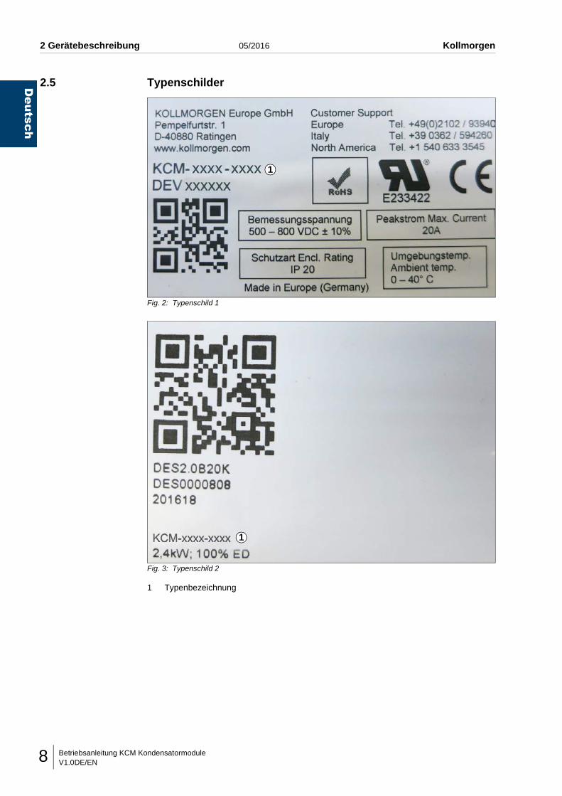
2.5 Typenschilder
Fig. 2: Typenschild 1
Fig. 3: Typenschild 2
1 Typenbezeichnung
1
1
Betriebsanleitung KCM KondensatormoduleV1.0DE/EN 9
Deutsch
Kollmorgen 05/2016 2 Gerätebeschreibung
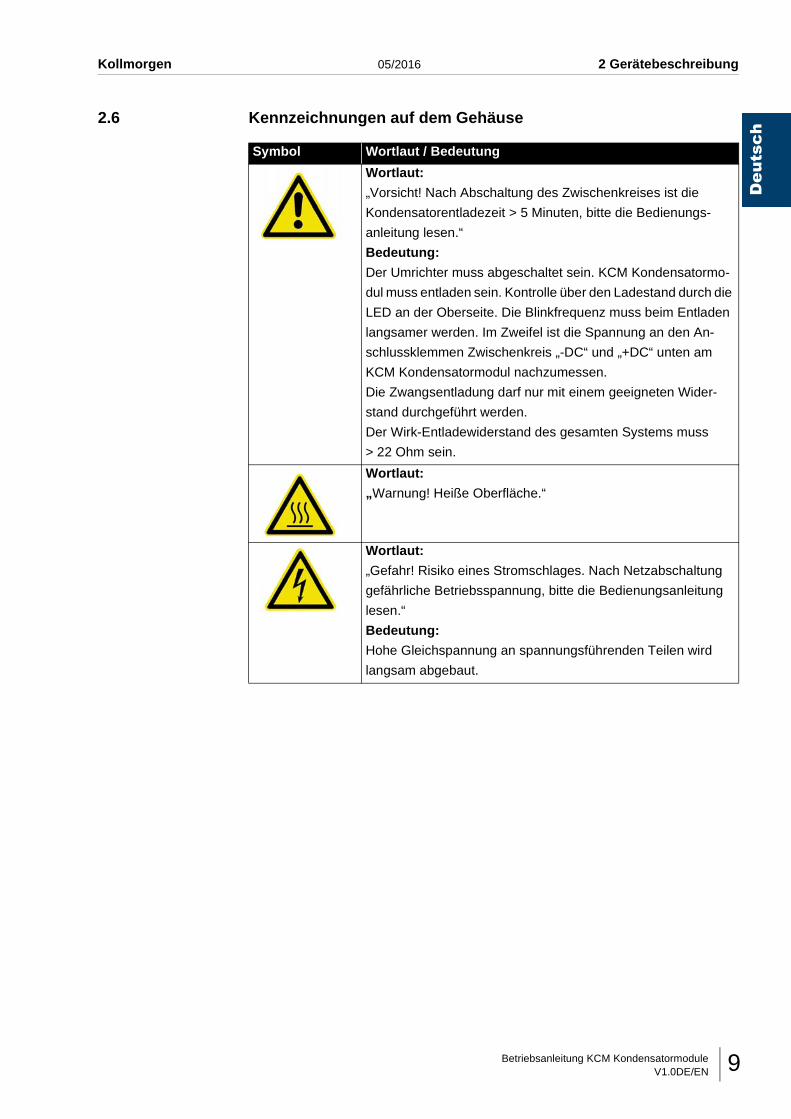
2.6 Kennzeichnungen auf dem Gehäuse
Symbol Wortlaut / Bedeutung
Wortlaut:
„Vorsicht! Nach Abschaltung des Zwischenkreises ist die
Kondensatorentladezeit > 5 Minuten, bitte die Bedienungs-
anleitung lesen.“
Bedeutung:
Der Umrichter muss abgeschaltet sein. KCM Kondensatormo-
dul muss entladen sein. Kontrolle über den Ladestand durch die
LED an der Oberseite. Die Blinkfrequenz muss beim Entladen
langsamer werden. Im Zweifel ist die Spannung an den An-
schlussklemmen Zwischenkreis „-DC“ und „+DC“ unten am
KCM Kondensatormodul nachzumessen.
Die Zwangsentladung darf nur mit einem geeigneten Wider-
stand durchgeführt werden.
Der Wirk-Entladewiderstand des gesamten Systems muss
> 22 Ohm sein.
Wortlaut:
„Warnung! Heiße Oberfläche.“
Wortlaut:
„Gefahr! Risiko eines Stromschlages. Nach Netzabschaltung
gefährliche Betriebsspannung, bitte die Bedienungsanleitung
lesen.“
Bedeutung:
Hohe Gleichspannung an spannungsführenden Teilen wird
langsam abgebaut.
Betriebsanleitung KCM KondensatormoduleV1.0DE/EN10
Deutsch
2 Gerätebeschreibung 05/2016 Kollmorgen
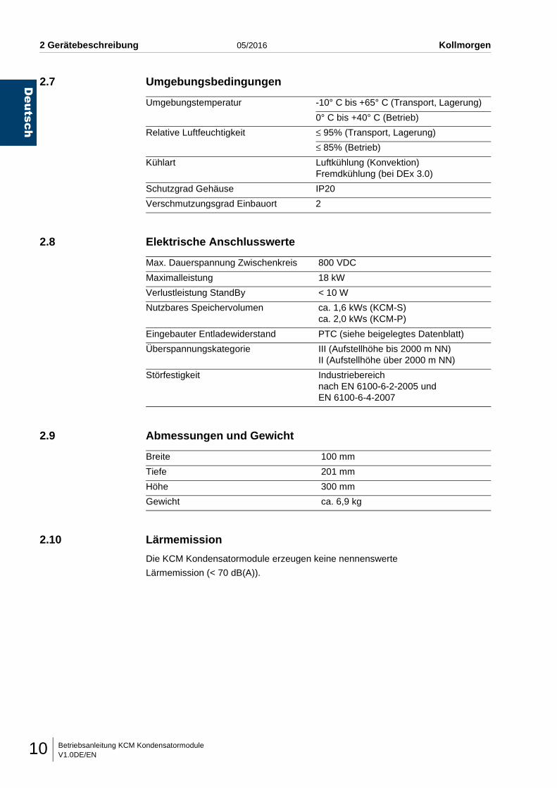
2.7 Umgebungsbedingungen
2.8 Elektrische Anschlusswerte
2.9 Abmessungen und Gewicht
2.10 Lärmemission
Die KCM Kondensatormodule erzeugen keine nennenswerte
Lärmemission (< 70 dB(A)).
Umgebungstemperatur -10° C bis +65° C (Transport, Lagerung)
0° C bis +40° C (Betrieb)
Relative Luftfeuchtigkeit ≤ 95% (Transport, Lagerung)
≤ 85% (Betrieb)
Kühlart Luftkühlung (Konvektion)Fremdkühlung (bei DEx 3.0)
Schutzgrad Gehäuse IP20
Verschmutzungsgrad Einbauort 2
Max. Dauerspannung Zwischenkreis 800 VDC
Maximalleistung 18 kW
Verlustleistung StandBy < 10 W
Nutzbares Speichervolumen ca. 1,6 kWs (KCM-S)ca. 2,0 kWs (KCM-P)
Eingebauter Entladewiderstand PTC (siehe beigelegtes Datenblatt)
Überspannungskategorie III (Aufstellhöhe bis 2000 m NN)II (Aufstellhöhe über 2000 m NN)
Störfestigkeit Industriebereichnach EN 6100-6-2-2005 und EN 6100-6-4-2007
Breite 100 mm
Tiefe 201 mm
Höhe 300 mm
Gewicht ca. 6,9 kg
Betriebsanleitung KCM KondensatormoduleV1.0DE/EN 11
Deutsch
Kollmorgen 05/2016 3 Grundlegende Sicherheitshinweise
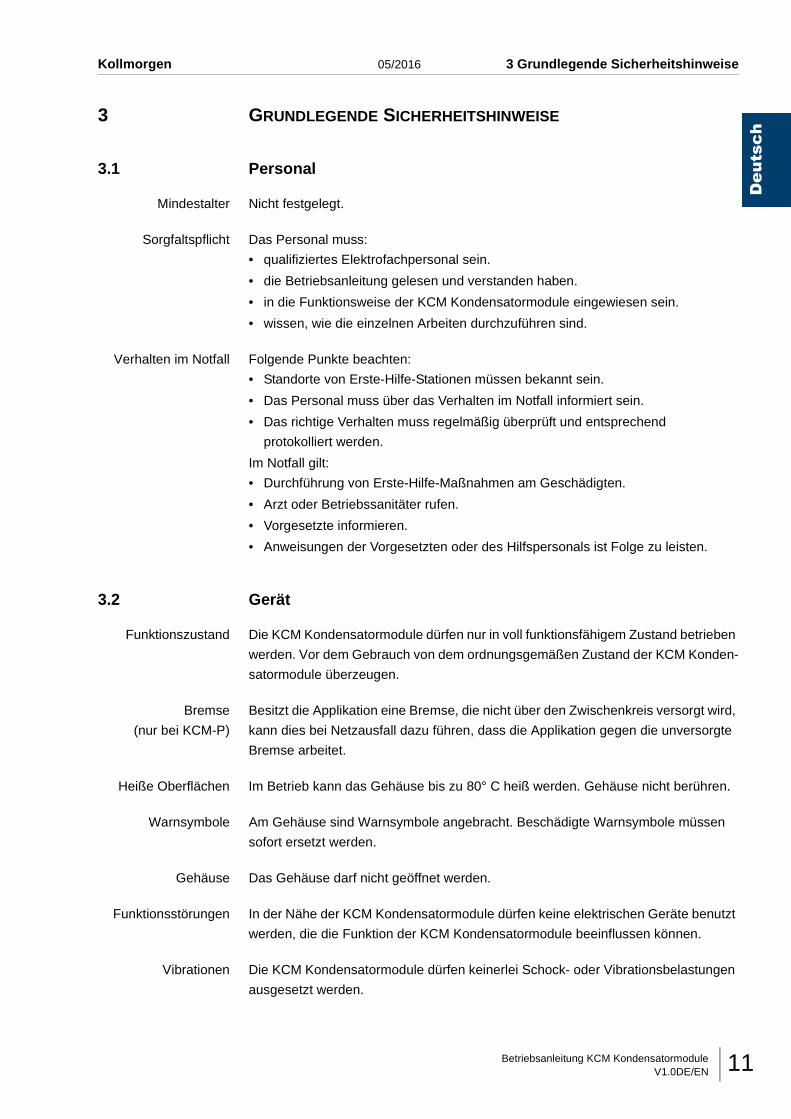
3 GRUNDLEGENDE SICHERHEITSHINWEISE
3.1 Personal
Mindestalter Nicht festgelegt.
Sorgfaltspflicht Das Personal muss:
• qualifiziertes Elektrofachpersonal sein.
• die Betriebsanleitung gelesen und verstanden haben.
• in die Funktionsweise der KCM Kondensatormodule eingewiesen sein.
• wissen, wie die einzelnen Arbeiten durchzuführen sind.
Verhalten im Notfall Folgende Punkte beachten:
• Standorte von Erste-Hilfe-Stationen müssen bekannt sein.
• Das Personal muss über das Verhalten im Notfall informiert sein.
• Das richtige Verhalten muss regelmäßig überprüft und entsprechend
protokolliert werden.
Im Notfall gilt:
• Durchführung von Erste-Hilfe-Maßnahmen am Geschädigten.
• Arzt oder Betriebssanitäter rufen.
• Vorgesetzte informieren.
• Anweisungen der Vorgesetzten oder des Hilfspersonals ist Folge zu leisten.
3.2 Gerät
Funktionszustand Die KCM Kondensatormodule dürfen nur in voll funktionsfähigem Zustand betrieben
werden. Vor dem Gebrauch von dem ordnungsgemäßen Zustand der KCM Konden-
satormodule überzeugen.
Bremse
(nur bei KCM-P)
Besitzt die Applikation eine Bremse, die nicht über den Zwischenkreis versorgt wird,
kann dies bei Netzausfall dazu führen, dass die Applikation gegen die unversorgte
Bremse arbeitet.
Heiße Oberflächen Im Betrieb kann das Gehäuse bis zu 80° C heiß werden. Gehäuse nicht berühren.
Warnsymbole Am Gehäuse sind Warnsymbole angebracht. Beschädigte Warnsymbole müssen
sofort ersetzt werden.
Gehäuse Das Gehäuse darf nicht geöffnet werden.
Funktionsstörungen In der Nähe der KCM Kondensatormodule dürfen keine elektrischen Geräte benutzt
werden, die die Funktion der KCM Kondensatormodule beeinflussen können.
Vibrationen Die KCM Kondensatormodule dürfen keinerlei Schock- oder Vibrationsbelastungen
ausgesetzt werden.
Betriebsanleitung KCM KondensatormoduleV1.0DE/EN12
Deutsch
3 Grundlegende Sicherheitshinweise 05/2016 Kollmorgen
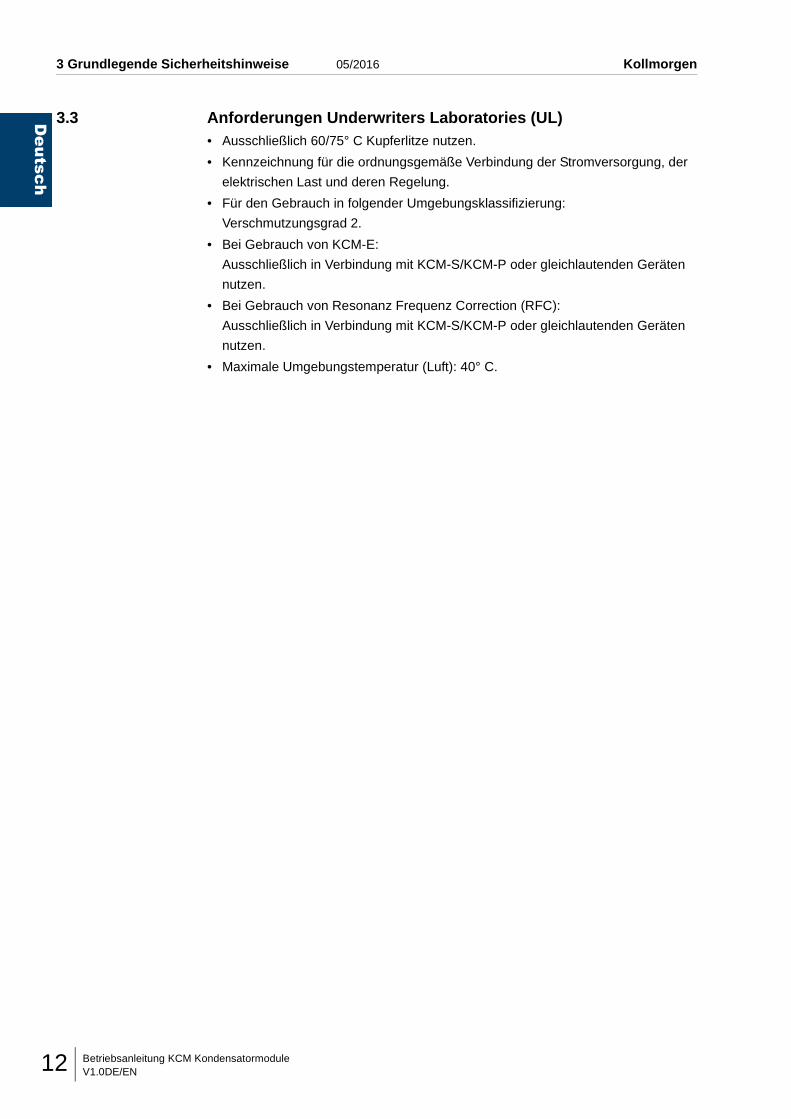
3.3 Anforderungen Underwriters Laboratories (UL)• Ausschließlich 60/75° C Kupferlitze nutzen.
• Kennzeichnung für die ordnungsgemäße Verbindung der Stromversorgung, der
elektrischen Last und deren Regelung.
• Für den Gebrauch in folgender Umgebungsklassifizierung:
Verschmutzungsgrad 2.
• Bei Gebrauch von KCM-E:
Ausschließlich in Verbindung mit KCM-S/KCM-P oder gleichlautenden Geräten
nutzen.
• Bei Gebrauch von Resonanz Frequenz Correction (RFC):
Ausschließlich in Verbindung mit KCM-S/KCM-P oder gleichlautenden Geräten
nutzen.
• Maximale Umgebungstemperatur (Luft): 40° C.
Betriebsanleitung KCM KondensatormoduleV1.0DE/EN 13
Deutsch
Kollmorgen 05/2016 4 Transport / Lagerung / Montage
4 TRANSPORT / LAGERUNG / MONTAGE
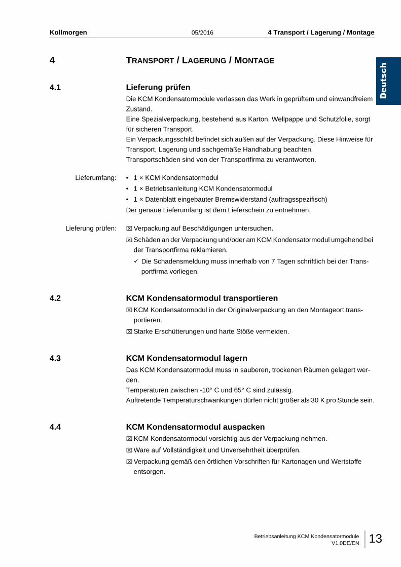
4.1 Lieferung prüfenDie KCM Kondensatormodule verlassen das Werk in geprüftem und einwandfreiem
Zustand.
Eine Spezialverpackung, bestehend aus Karton, Wellpappe und Schutzfolie, sorgt
für sicheren Transport.
Ein Verpackungsschild befindet sich außen auf der Verpackung. Diese Hinweise für
Transport, Lagerung und sachgemäße Handhabung beachten.
Transportschäden sind von der Transportfirma zu verantworten.
Lieferumfang: • 1 × KCM Kondensatormodul
• 1 × Betriebsanleitung KCM Kondensatormodul
• 1 × Datenblatt eingebauter Bremswiderstand (auftragsspezifisch)
Der genaue Lieferumfang ist dem Lieferschein zu entnehmen.
Lieferung prüfen: ⌧Verpackung auf Beschädigungen untersuchen.
⌧Schäden an der Verpackung und/oder am KCM Kondensatormodul umgehend bei
der Transportfirma reklamieren.
Die Schadensmeldung muss innerhalb von 7 Tagen schriftlich bei der Trans-
portfirma vorliegen.
4.2 KCM Kondensatormodul transportieren⌧KCM Kondensatormodul in der Originalverpackung an den Montageort trans-
portieren.
⌧Starke Erschütterungen und harte Stöße vermeiden.
4.3 KCM Kondensatormodul lagernDas KCM Kondensatormodul muss in sauberen, trockenen Räumen gelagert wer-
den.
Temperaturen zwischen -10° C und 65° C sind zulässig.
Auftretende Temperaturschwankungen dürfen nicht größer als 30 K pro Stunde sein.
4.4 KCM Kondensatormodul auspacken⌧KCM Kondensatormodul vorsichtig aus der Verpackung nehmen.
⌧Ware auf Vollständigkeit und Unversehrtheit überprüfen.
⌧Verpackung gemäß den örtlichen Vorschriften für Kartonagen und Wertstoffe
entsorgen.
Betriebsanleitung KCM KondensatormoduleV1.0DE/EN14
Deutsch
4 Transport / Lagerung / Montage 05/2016 Kollmorgen
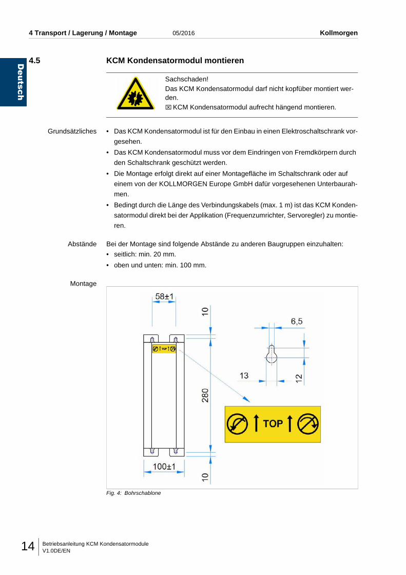
4.5 KCM Kondensatormodul montieren
Grundsätzliches • Das KCM Kondensatormodul ist für den Einbau in einen Elektroschaltschrank vor-
gesehen.
• Das KCM Kondensatormodul muss vor dem Eindringen von Fremdkörpern durch
den Schaltschrank geschützt werden.
• Die Montage erfolgt direkt auf einer Montagefläche im Schaltschrank oder auf
einem von der KOLLMORGEN Europe GmbH dafür vorgesehenen Unterbaurah-
men.
• Bedingt durch die Länge des Verbindungskabels (max. 1 m) ist das KCM Konden-
satormodul direkt bei der Applikation (Frequenzumrichter, Servoregler) zu montie-
ren.
Abstände Bei der Montage sind folgende Abstände zu anderen Baugruppen einzuhalten:
• seitlich: min. 20 mm.
• oben und unten: min. 100 mm.
Montage
Fig. 4: Bohrschablone
Sachschaden!Das KCM Kondensatormodul darf nicht kopfüber montiert wer-den.⌧KCM Kondensatormodul aufrecht hängend montieren.
Betriebsanleitung KCM KondensatormoduleV1.0DE/EN 15
Deutsch
Kollmorgen 05/2016 4 Transport / Lagerung / Montage
⌧KCM Kondensatormodul gemäß der Bohrschablone mit vier Schrauben (M6) auf-
recht hängend wie folgt montieren:
Zuerst die beiden oberen Schrauben einschrauben, dann das KCM Kondensator-
modul einhängen und danach die beiden unteren Schrauben einschrauben.
Leistungsanschluss ist unten.
⌧Alle Schrauben handfest anziehen und den festen Sitz kontrollieren.
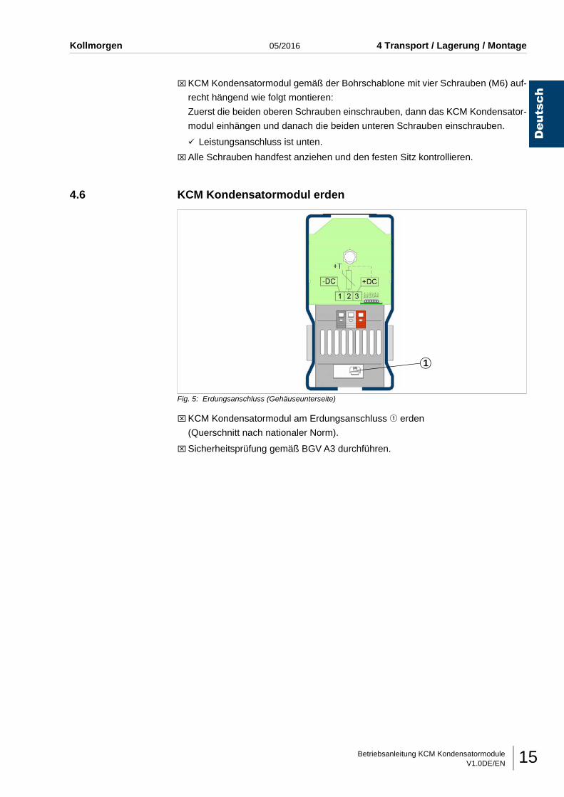
4.6 KCM Kondensatormodul erden
Fig. 5: Erdungsanschluss (Gehäuseunterseite)
⌧KCM Kondensatormodul am Erdungsanschluss q erden
(Querschnitt nach nationaler Norm).
⌧Sicherheitsprüfung gemäß BGV A3 durchführen.
1
Betriebsanleitung KCM KondensatormoduleV1.0DE/EN16
Deutsch
5 Inbetriebnahme 05/2016 Kollmorgen
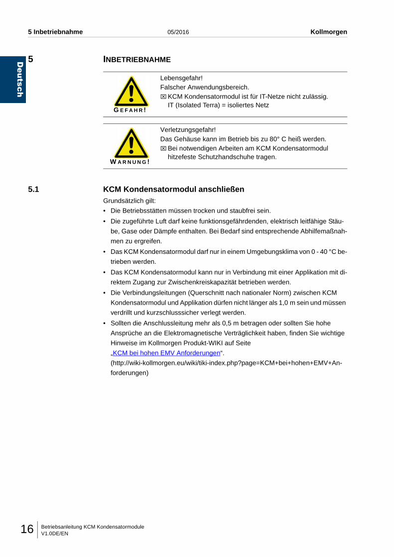
5 INBETRIEBNAHME
5.1 KCM Kondensatormodul anschließenGrundsätzlich gilt:
• Die Betriebsstätten müssen trocken und staubfrei sein.
• Die zugeführte Luft darf keine funktionsgefährdenden, elektrisch leitfähige Stäu-
be, Gase oder Dämpfe enthalten. Bei Bedarf sind entsprechende Abhilfemaßnah-
men zu ergreifen.
• Das KCM Kondensatormodul darf nur in einem Umgebungsklima von 0 - 40 °C be-
trieben werden.
• Das KCM Kondensatormodul kann nur in Verbindung mit einer Applikation mit di-
rektem Zugang zur Zwischenkreiskapazität betrieben werden.
• Die Verbindungsleitungen (Querschnitt nach nationaler Norm) zwischen KCM
Kondensatormodul und Applikation dürfen nicht länger als 1,0 m sein und müssen
verdrillt und kurzschlusssicher verlegt werden.
• Sollten die Anschlussleitung mehr als 0,5 m betragen oder sollten Sie hohe
Ansprüche an die Elektromagnetische Verträglichkeit haben, finden Sie wichtige
Hinweise im Kollmorgen Produkt-WIKI auf Seite
„KCM bei hohen EMV Anforderungen“.
(http://wiki-kollmorgen.eu/wiki/tiki-index.php?page=KCM+bei+hohen+EMV+An-
forderungen)
G E F A H R !
Lebensgefahr!Falscher Anwendungsbereich.⌧KCM Kondensatormodul ist für IT-Netze nicht zulässig.
IT (Isolated Terra) = isoliertes Netz
W A R N U N G !
Verletzungsgefahr!Das Gehäuse kann im Betrieb bis zu 80° C heiß werden.⌧Bei notwendigen Arbeiten am KCM Kondensatormodul
hitzefeste Schutzhandschuhe tragen.
Betriebsanleitung KCM KondensatormoduleV1.0DE/EN 17
Deutsch
Kollmorgen 05/2016 5 Inbetriebnahme
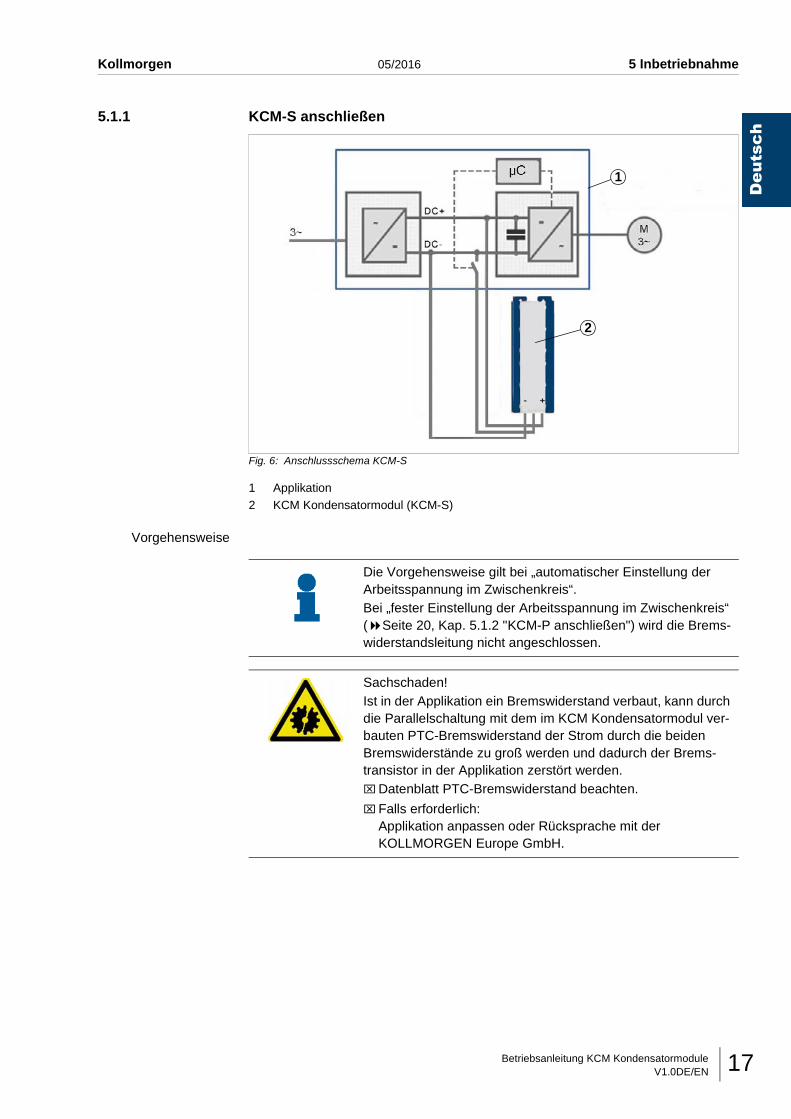
5.1.1 KCM-S anschließen
Fig. 6: Anschlussschema KCM-S
1 Applikation2 KCM Kondensatormodul (KCM-S)
Vorgehensweise
1
2
Die Vorgehensweise gilt bei „automatischer Einstellung der Arbeitsspannung im Zwischenkreis“.Bei „fester Einstellung der Arbeitsspannung im Zwischenkreis“ ( Seite 20, Kap. 5.1.2 "KCM-P anschließen") wird die Brems-widerstandsleitung nicht angeschlossen.
Sachschaden!Ist in der Applikation ein Bremswiderstand verbaut, kann durch die Parallelschaltung mit dem im KCM Kondensatormodul ver-bauten PTC-Bremswiderstand der Strom durch die beiden Bremswiderstände zu groß werden und dadurch der Brems-transistor in der Applikation zerstört werden.⌧Datenblatt PTC-Bremswiderstand beachten.
⌧ Falls erforderlich: Applikation anpassen oder Rücksprache mit der KOLLMORGEN Europe GmbH.
Betriebsanleitung KCM KondensatormoduleV1.0DE/EN18
Deutsch
5 Inbetriebnahme 05/2016 Kollmorgen
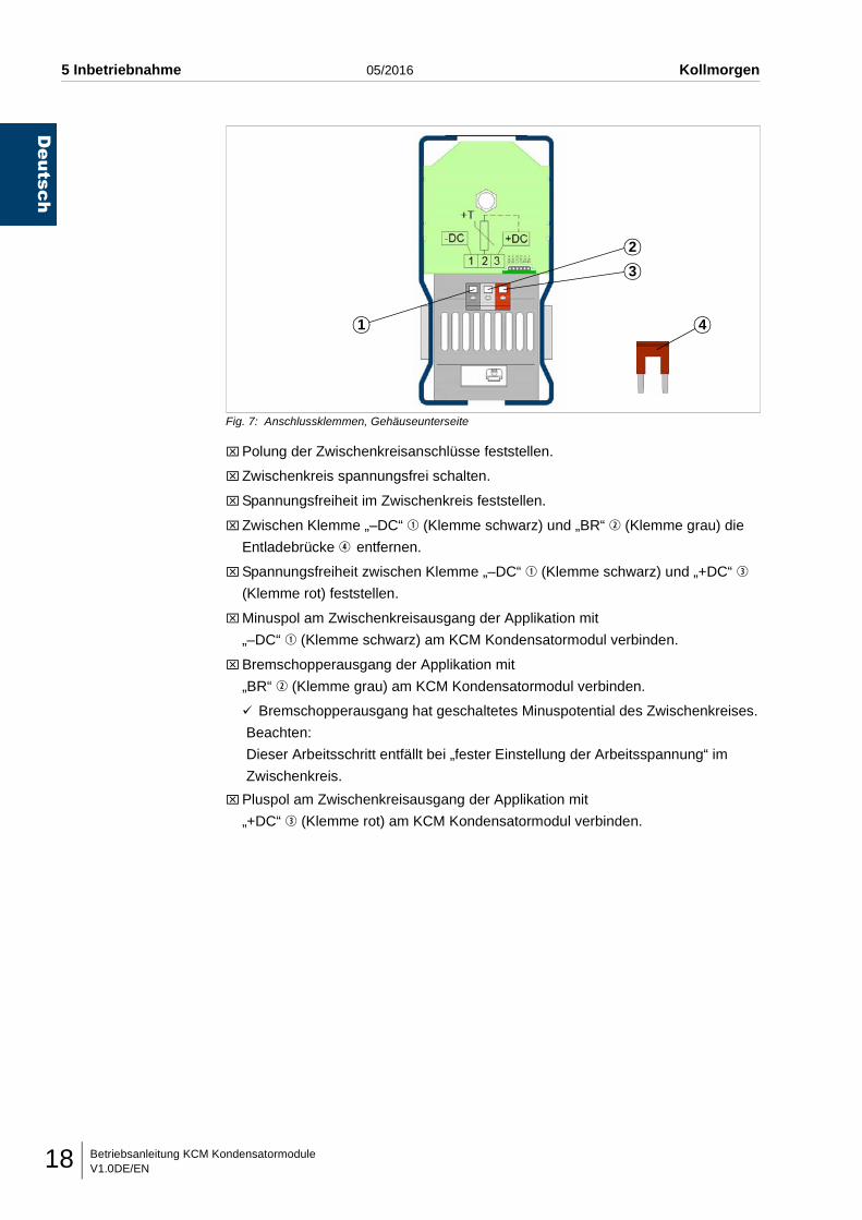
Fig. 7: Anschlussklemmen, Gehäuseunterseite
⌧Polung der Zwischenkreisanschlüsse feststellen.
⌧Zwischenkreis spannungsfrei schalten.
⌧Spannungsfreiheit im Zwischenkreis feststellen.
⌧Zwischen Klemme „–DC“ q (Klemme schwarz) und „BR“ w (Klemme grau) die
Entladebrücke r entfernen.
⌧Spannungsfreiheit zwischen Klemme „–DC“ q (Klemme schwarz) und „+DC“ e
(Klemme rot) feststellen.
⌧Minuspol am Zwischenkreisausgang der Applikation mit
„–DC“ q (Klemme schwarz) am KCM Kondensatormodul verbinden.
⌧Bremschopperausgang der Applikation mit
„BR“ w (Klemme grau) am KCM Kondensatormodul verbinden.
Bremschopperausgang hat geschaltetes Minuspotential des Zwischenkreises.
Beachten:
Dieser Arbeitsschritt entfällt bei „fester Einstellung der Arbeitsspannung“ im
Zwischenkreis.
⌧Pluspol am Zwischenkreisausgang der Applikation mit
„+DC“ e (Klemme rot) am KCM Kondensatormodul verbinden.
1
2
3
4
Betriebsanleitung KCM KondensatormoduleV1.0DE/EN 19
Deutsch
Kollmorgen 05/2016 5 Inbetriebnahme
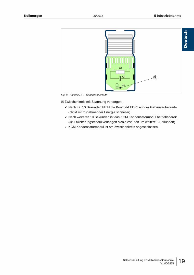
Fig. 8: Kontroll-LED, Gehäuseoberseite
⌧Zwischenkreis mit Spannung versorgen.
Nach ca. 10 Sekunden blinkt die Kontroll-LED t auf der Gehäuseoberseite
(blinkt mit zunehmender Energie schneller).
Nach weiteren 10 Sekunden ist das KCM Kondensatormodul betriebsbereit
(Je Erweiterungsmodul verlängert sich diese Zeit um weitere 5 Sekunden).
KCM Kondensatormodul ist am Zwischenkreis angeschlossen.
5
Betriebsanleitung KCM KondensatormoduleV1.0DE/EN20
Deutsch
5 Inbetriebnahme 05/2016 Kollmorgen
5.1.2 KCM-P anschließen
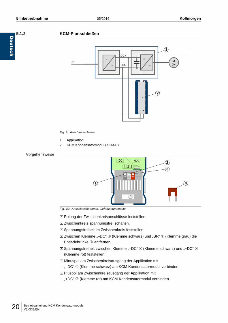
Fig. 9: Anschlussschema
1 Applikation2 KCM Kondensatormodul (KCM-P)
Vorgehensweise
Fig. 10: Anschlussklemmen, Gehäuseunterseite
⌧Polung der Zwischenkreisanschlüsse feststellen.
⌧Zwischenkreis spannungsfrei schalten.
⌧Spannungsfreiheit im Zwischenkreis feststellen.
⌧Zwischen Klemme „–DC“ q (Klemme schwarz) und „BR“ w (Klemme grau) die
Entladebrücke r entfernen.
⌧Spannungsfreiheit zwischen Klemme „–DC“ q (Klemme schwarz) und „+DC“ e
(Klemme rot) feststellen.
⌧Minuspol am Zwischenkreisausgang der Applikation mit
„–DC“ q (Klemme schwarz) am KCM Kondensatormodul verbinden.
⌧Pluspol am Zwischenkreisausgang der Applikation mit
„+DC“ e (Klemme rot) am KCM Kondensatormodul verbinden.
1
2
1
2
3
4
Betriebsanleitung KCM KondensatormoduleV1.0DE/EN 21
Deutsch
Kollmorgen 05/2016 5 Inbetriebnahme
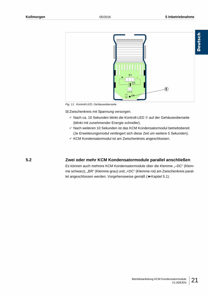
Fig. 11: Kontroll-LED, Gehäuseoberseite
⌧Zwischenkreis mit Spannung versorgen.
Nach ca. 10 Sekunden blinkt die Kontroll-LED t auf der Gehäuseoberseite
(blinkt mit zunehmender Energie schneller).
Nach weiteren 10 Sekunden ist das KCM Kondensatormodul betriebsbereit
(Je Erweiterungsmodul verlängert sich diese Zeit um weitere 5 Sekunden).
KCM Kondensatormodul ist am Zwischenkreis angeschlossen.
5.2 Zwei oder mehr KCM Kondensatormodule parallel anschließenEs können auch mehrere KCM Kondensatormodule über die Klemme „–DC“ (Klem-
me schwarz), „BR“ (Klemme grau) und „+DC“ (Klemme rot) am Zwischenkreis paral-
lel angeschlossen werden. Vorgehensweise gemäß ( Kapitel 5.1).
5
Betriebsanleitung KCM KondensatormoduleV1.0DE/EN22
Deutsch
5 Inbetriebnahme 05/2016 Kollmorgen
5.3 Zwei oder mehr Applikationen mit einem Zwischenkreisverbundan einem KCM Kondensatormodul anschließen
Nur eine Applikation hat einen Bremswiderstand
⌧KCM Kondensatormodul an dieser Applikation anschließen.
⌧Bremswiderstandsleitung an dieser Applikation anschließen.
Mehrere Applikationen haben einen Bremswiderstand und es ist
sichergestellt, dass immer alle Applikationen gleichzeitig bremsen
⌧KCM Kondensatormodul an eine beliebige Applikation anschließen.
⌧Bremswiderstandsleitung an der gleichen Applikation anschließen.
Mehrere Applikationen haben einen Bremswiderstand und es ist nicht
sichergestellt, dass immer alle Applikationen gleichzeitig bremsen
(nur bei KCM Kondensatormodul mit fester Einstellung der Arbeitsspannung
im Zwischenkreis möglich)
⌧KCM Kondensatormodul an einer beliebigen Applikation anschließen.
⌧Bremswiderstandsleitung nicht anschließen (feste Voreinstellung).

Betriebsanleitung KCM KondensatormoduleV1.0DE/EN 23
Deutsch
Kollmorgen 05/2016 5 Inbetriebnahme
5.4 RS422-Kommunikationsschnittstelle anschließen
Fig. 12: Gehäuseunterseite, RS422-Kommunikationsschnittstelle X4
Grundsätzliches • Die Kommunikationsschnittstelle q ist zum Austauschen von Daten mit dem KCM
Kondensatormodul.
• Die Schnittstelle muss mit einer externen RS422-Kommunikationsschnittstelle
verbunden werden.
Belegung Stecker X4
Fig. 13: Pinbelegung Stecker X4 und externe Schnittstelle
1
Pin Signal Beschreibung
1 RX+ verbinden mit TX+ externe Schnittstelle
2 RX- verbinden mit TX- externe Schnittstelle
3 GND verbinden mit GND
4 +12V verbinden mit Versorgungsspannung +5...16 V
5 TX+ verbinden mit RX+ externe Schnittstelle
6 TX- verbinden mit RX- externe Schnittstelle
X4
RX-RX++5...16 VGNDTX-TX+
Betriebsanleitung KCM KondensatormoduleV1.0DE/EN24
Deutsch
5 Inbetriebnahme 05/2016 Kollmorgen
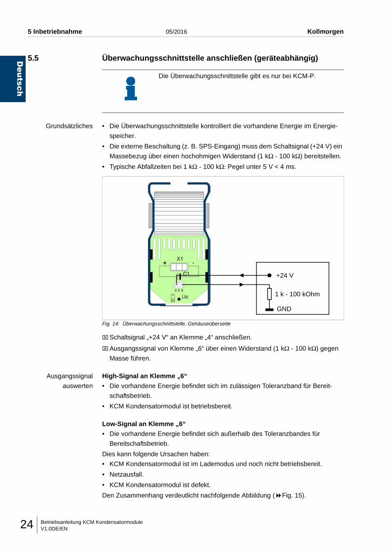
5.5 Überwachungsschnittstelle anschließen (geräteabhängig)
Grundsätzliches • Die Überwachungsschnittstelle kontrolliert die vorhandene Energie im Energie-
speicher.
• Die externe Beschaltung (z. B. SPS-Eingang) muss dem Schaltsignal (+24 V) ein
Massebezug über einen hochohmigen Widerstand (1 kΩ - 100 kΩ) bereitstellen.
• Typische Abfallzeiten bei 1 kΩ - 100 kΩ: Pegel unter 5 V < 4 ms.
Fig. 14: Überwachungsschnittstelle, Gehäuseoberseite
⌧Schaltsignal „+24 V“ an Klemme „4“ anschließen.
⌧Ausgangssignal von Klemme „6“ über einen Widerstand (1 kΩ - 100 kΩ) gegen
Masse führen.
Ausgangssignal
auswerten
High-Signal an Klemme „6“
• Die vorhandene Energie befindet sich im zulässigen Toleranzband für Bereit-
schaftsbetrieb.
• KCM Kondensatormodul ist betriebsbereit.
Low-Signal an Klemme „6“
• Die vorhandene Energie befindet sich außerhalb des Toleranzbandes für
Bereitschaftsbetrieb.
Dies kann folgende Ursachen haben:
• KCM Kondensatormodul ist im Lademodus und noch nicht betriebsbereit.
• Netzausfall.
• KCM Kondensatormodul ist defekt.
Den Zusammenhang verdeutlicht nachfolgende Abbildung ( Fig. 15).
Die Überwachungsschnittstelle gibt es nur bei KCM-P.
+24 V
1 k - 100 kOhm
GND
Betriebsanleitung KCM KondensatormoduleV1.0DE/EN 25
Deutsch
Kollmorgen 05/2016 5 Inbetriebnahme
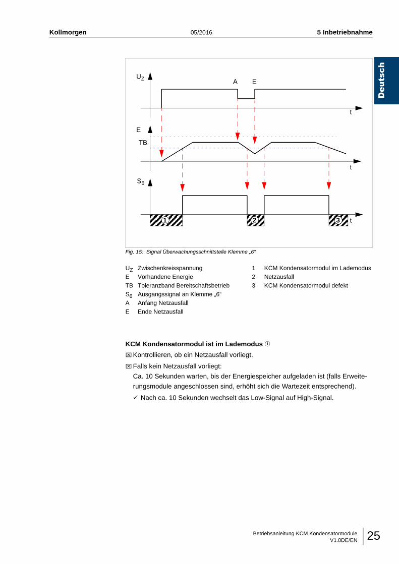
Fig. 15: Signal Überwachungsschnittstelle Klemme „6“
KCM Kondensatormodul ist im Lademodus q
⌧Kontrollieren, ob ein Netzausfall vorliegt.
⌧Falls kein Netzausfall vorliegt:
Ca. 10 Sekunden warten, bis der Energiespeicher aufgeladen ist (falls Erweite-
rungsmodule angeschlossen sind, erhöht sich die Wartezeit entsprechend).
Nach ca. 10 Sekunden wechselt das Low-Signal auf High-Signal.
UZ ZwischenkreisspannungE Vorhandene Energie
TB Toleranzband BereitschaftsbetriebS6 Ausgangssignal an Klemme „6“A Anfang Netzausfall
E Ende Netzausfall
1 KCM Kondensatormodul im Lademodus2 Netzausfall
3 KCM Kondensatormodul defekt
AUZ
E
t
t
S6
TB
E
1 2 3
t
Betriebsanleitung KCM KondensatormoduleV1.0DE/EN26
Deutsch
5 Inbetriebnahme 05/2016 Kollmorgen
Netzausfall w ( Fig. 15)
• Wird durch die Überwachungsschnittstelle ein Netzausfall erkannt, verbleiben
noch mindestens 80% der gespeicherten Energie. Diese Energie kann genutzt
werden, um die Applikation sicher in den Stillstand zu führen.
• Es ist zu beachten, dass durch das Herunterfahren der Applikation unter Umstän-
den wieder Energie frei wird, welche zu einem Ansteigen der Zwischenkreis-
spannung führt.
• Wenn die Zwischenkreisspannung weit genug ansteigt, wird die Energie genutzt,
um den Energiespeicher wieder zu laden. Wird der Energiespeicher so weit gela-
den, dass die Energie wieder im zulässigen Toleranzband für Bereitschaftsbetrieb
liegt, führt dies zu einem High-Signal an Klemme „6“, welches fälschlicherweise
als Wiederkehren des Netzes interpretiert werden könnte.
⌧Kontrollieren, ob ein Netzausfall vorliegt.
KCM Kondensatormodul arbeitet nicht ordnungsgemäß e ( Fig. 15)
Falls ein Low-Signal an Klemme „6“ anliegt, obwohl
• KCM Kondensatormodul längere Zeit in Betrieb (aufgeladen) ist und
• kein Netzausfall vorliegt,
ist das KCM Kondensatormodul defekt.
⌧Umgehend Hersteller bezüglich weiterem Vorgehen kontaktieren.
Betriebsanleitung KCM KondensatormoduleV1.0DE/EN 27
Deutsch
Kollmorgen 05/2016 5 Inbetriebnahme
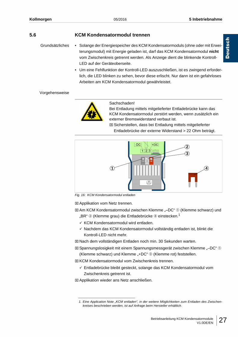
5.6 KCM Kondensatormodul trennen
Grundsätzliches • Solange der Energiespeicher des KCM Kondensatormoduls (ohne oder mit Erwei-
terungsmodul) mit Energie geladen ist, darf das KCM Kondensatormodul nicht
vom Zwischenkreis getrennt werden. Als Anzeige dient die blinkende Kontroll-
LED auf der Geräteoberseite.
• Um eine Fehlfunktion der Kontroll-LED auszuschließen, ist es zwingend erforder-
lich, die LED blinken zu sehen, bevor diese erlischt. Nur dann ist ein gefahrloses
Arbeiten am KCM Kondensatormodul gewährleistet.
Vorgehensweise
Fig. 16: KCM Kondensatormodul entladen
⌧Applikation vom Netz trennen.
⌧Am KCM Kondensatormodul zwischen Klemme „–DC“ q (Klemme schwarz) und
„BR“ w (Klemme grau) die Entladebrücke r einstecken.1
KCM Kondensatormodul wird entladen.
Nachdem das KCM Kondensatormodul vollständig entladen ist, blinkt die
Kontroll-LED nicht mehr.
⌧Nach dem vollständigen Entladen noch min. 30 Sekunden warten.
⌧Spannungslosigkeit mit einem Spannungsmessgerät zwischen Klemme „–DC“ q
(Klemme schwarz) und Klemme „+DC“ e (Klemme rot) feststellen.
⌧KCM Kondensatormodul vom Zwischenkreis trennen.
Entladebrücke bleibt gesteckt, solange das KCM Kondensatormodul vom
Zwischenkreis getrennt ist.
⌧Applikation wieder ans Netz anschließen.
Sachschaden!Bei Entladung mittels mitgelieferter Entladebrücke kann das KCM Kondensatormodul zerstört werden, wenn zusätzlich ein externer Bremswiderstand verbaut ist.⌧Sicherstellen, dass bei Entladung mittels mitgelieferter
Entladebrücke der externe Widerstand > 22 Ohm beträgt.
1. Eine Application Note „KCM entladen“, in der weitere Möglichkeiten zum Entladen des Zwischen-kreises beschrieben werden, ist auf Anfrage beim Hersteller erhältlich.
1
2
3
4
Betriebsanleitung KCM KondensatormoduleV1.0DE/EN28
Deutsch
5 Inbetriebnahme 05/2016 Kollmorgen
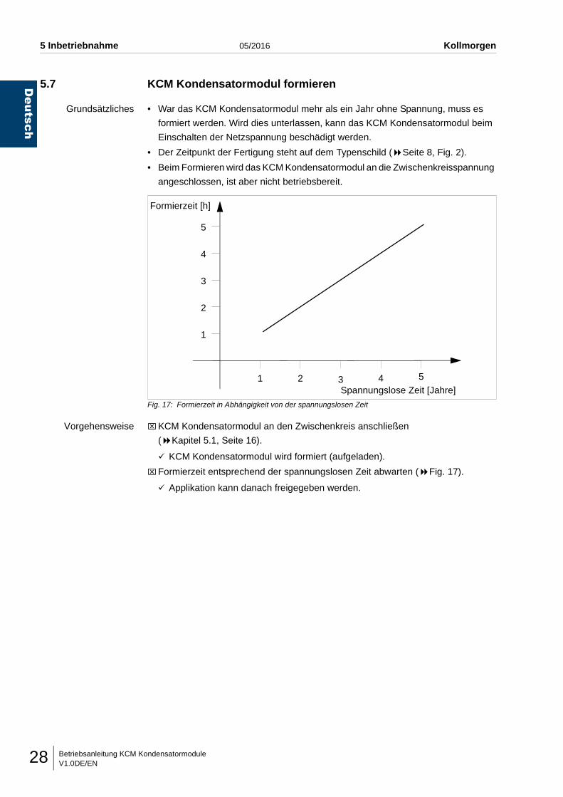
5.7 KCM Kondensatormodul formieren
Grundsätzliches • War das KCM Kondensatormodul mehr als ein Jahr ohne Spannung, muss es
formiert werden. Wird dies unterlassen, kann das KCM Kondensatormodul beim
Einschalten der Netzspannung beschädigt werden.
• Der Zeitpunkt der Fertigung steht auf dem Typenschild ( Seite 8, Fig. 2).
• Beim Formieren wird das KCM Kondensatormodul an die Zwischenkreisspannung
angeschlossen, ist aber nicht betriebsbereit.
Fig. 17: Formierzeit in Abhängigkeit von der spannungslosen Zeit
Vorgehensweise ⌧KCM Kondensatormodul an den Zwischenkreis anschließen
( Kapitel 5.1, Seite 16).
KCM Kondensatormodul wird formiert (aufgeladen).
⌧Formierzeit entsprechend der spannungslosen Zeit abwarten ( Fig. 17).
Applikation kann danach freigegeben werden.
Spannungslose Zeit [Jahre]
Formierzeit [h]
5
4
3
2
1
1 2 3 4 5
Betriebsanleitung KCM KondensatormoduleV1.0DE/EN 29
Deutsch
Kollmorgen 05/2016 6 Sonstige Tätigkeiten
6 SONSTIGE TÄTIGKEITEN
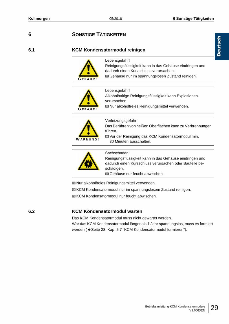
6.1 KCM Kondensatormodul reinigen
⌧Nur alkoholfreies Reinigungsmittel verwenden.
⌧KCM Kondensatormodul nur im spannungslosem Zustand reinigen.
⌧KCM Kondensatormodul nur feucht abwischen.
6.2 KCM Kondensatormodul wartenDas KCM Kondensatormodul muss nicht gewartet werden.
War das KCM Kondensatormodul länger als 1 Jahr spannungslos, muss es formiert
werden ( Seite 28, Kap. 5.7 "KCM Kondensatormodul formieren").
G E F A H R !
Lebensgefahr!Reinigungsflüssigkeit kann in das Gehäuse eindringen und dadurch einen Kurzschluss verursachen.⌧Gehäuse nur im spannungslosen Zustand reinigen.
G E F A H R !
Lebensgefahr!Alkoholhaltige Reinigungsflüssigkeit kann Explosionen verursachen.⌧Nur alkoholfreies Reinigungsmittel verwenden.
W A R N U N G !
Verletzungsgefahr!Das Berühren von heißen Oberflächen kann zu Verbrennungen führen.⌧Vor der Reinigung das KCM Kondensatormodul min.
30 Minuten ausschalten.
Sachschaden!Reinigungsflüssigkeit kann in das Gehäuse eindringen und dadurch einen Kurzschluss verursachen oder Bauteile be-schädigen.⌧Gehäuse nur feucht abwischen.
Betriebsanleitung KCM KondensatormoduleV1.0DE/EN30
Deutsch
6 Sonstige Tätigkeiten 05/2016 Kollmorgen
6.3 KCM Kondensatormodul reparierenEine defektes KCM Kondensatormodul kann nur vom Hersteller repariert werden.
6.4 KCM Kondensatormodul entsorgen⌧KCM Kondensatormodul trennen
( Seite 27, Kap. 5.6 "KCM Kondensatormodul trennen").
⌧KCM Kondensatormodul ausbauen.
⌧KCM Kondensatormodul an den Hersteller zurückschicken.
Betriebsanleitung KCM KondensatormoduleV1.0DE/EN 31
Deutsch
Kollmorgen 05/2016 7 Erweiterungsmodul
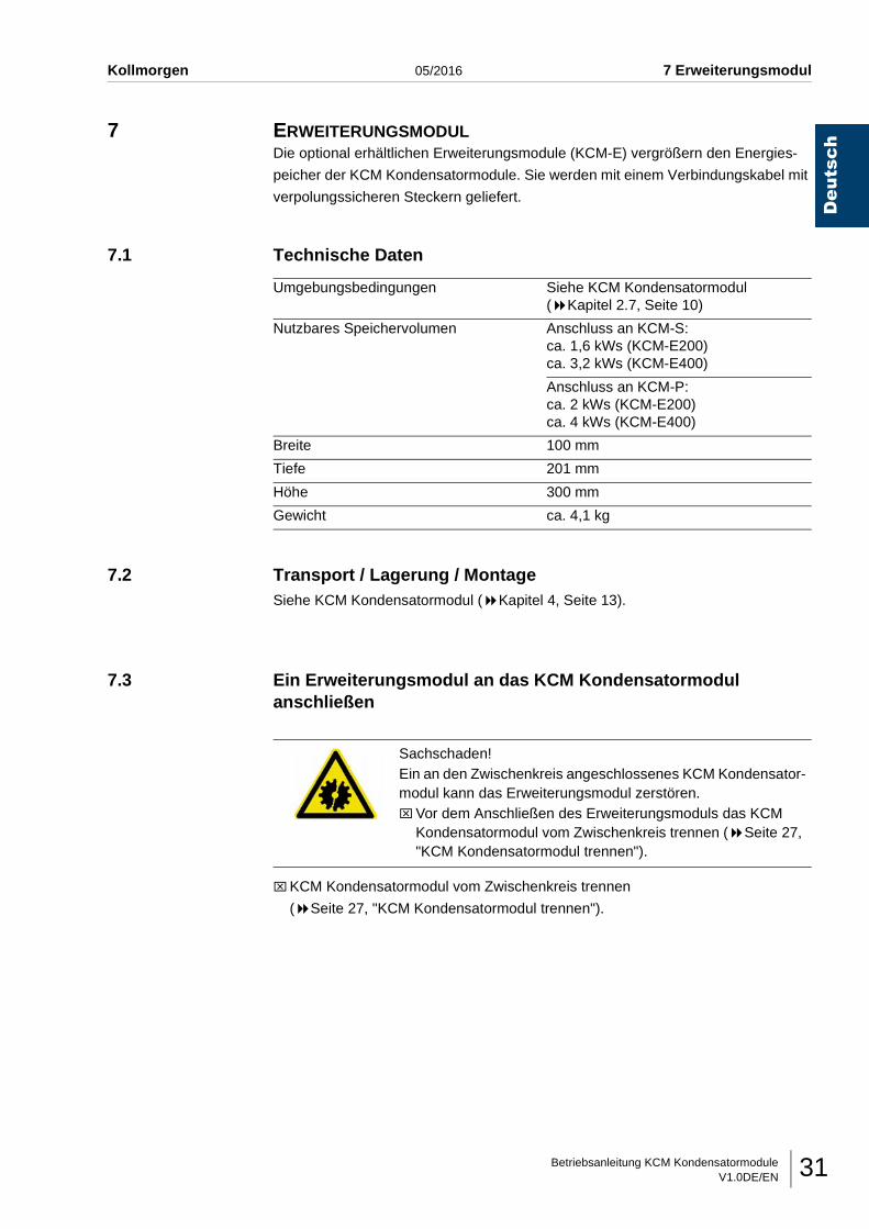
7 ERWEITERUNGSMODULDie optional erhältlichen Erweiterungsmodule (KCM-E) vergrößern den Energies-
peicher der KCM Kondensatormodule. Sie werden mit einem Verbindungskabel mit
verpolungssicheren Steckern geliefert.
7.1 Technische Daten
7.2 Transport / Lagerung / MontageSiehe KCM Kondensatormodul ( Kapitel 4, Seite 13).
7.3 Ein Erweiterungsmodul an das KCM Kondensatormodul anschließen
⌧KCM Kondensatormodul vom Zwischenkreis trennen
( Seite 27, "KCM Kondensatormodul trennen").
Umgebungsbedingungen Siehe KCM Kondensatormodul( Kapitel 2.7, Seite 10)
Nutzbares Speichervolumen Anschluss an KCM-S:ca. 1,6 kWs (KCM-E200)ca. 3,2 kWs (KCM-E400)
Anschluss an KCM-P:ca. 2 kWs (KCM-E200)ca. 4 kWs (KCM-E400)
Breite 100 mm
Tiefe 201 mm
Höhe 300 mm
Gewicht ca. 4,1 kg
Sachschaden!Ein an den Zwischenkreis angeschlossenes KCM Kondensator-modul kann das Erweiterungsmodul zerstören.⌧Vor dem Anschließen des Erweiterungsmoduls das KCM
Kondensatormodul vom Zwischenkreis trennen ( Seite 27, "KCM Kondensatormodul trennen").
Betriebsanleitung KCM KondensatormoduleV1.0DE/EN32
Deutsch
7 Erweiterungsmodul 05/2016 Kollmorgen
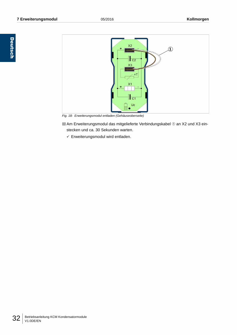
Fig. 18: Erweiterungsmodul entladen (Gehäuseoberseite)
⌧Am Erweiterungsmodul das mitgelieferte Verbindungskabel q an X2 und X3 ein-
stecken und ca. 30 Sekunden warten.
Erweiterungsmodul wird entladen.
1
Betriebsanleitung KCM KondensatormoduleV1.0DE/EN 33
Deutsch
Kollmorgen 05/2016 7 Erweiterungsmodul
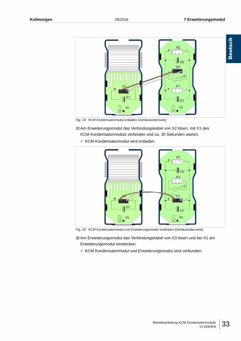
Fig. 19: KCM Kondensatormodul entladen (Gehäuseoberseite)
⌧Am Erweiterungsmodul das Verbindungskabel von X2 lösen, mit X1 des
KCM Kondensatormoduls verbinden und ca. 30 Sekunden warten.
KCM Kondensatormodul wird entladen.
Fig. 20: KCM Kondensatormodul und Erweiterungsmodul verbinden (Gehäuseoberseite)
⌧Am Erweiterungsmodul das Verbindungskabel von X3 lösen und bei X1 am
Erweiterungsmodul einstecken.
KCM Kondensatormodul und Erweiterungsmodul sind verbunden.
Betriebsanleitung KCM KondensatormoduleV1.0DE/EN34
Deutsch
7 Erweiterungsmodul 05/2016 Kollmorgen
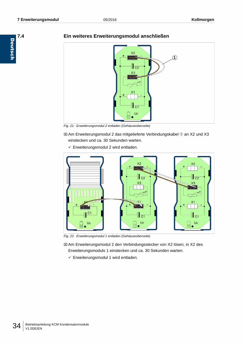
7.4 Ein weiteres Erweiterungsmodul anschließen
Fig. 21: Erweiterungsmodul 2 entladen (Gehäuseoberseite)
⌧Am Erweiterungsmodul 2 das mitgelieferte Verbindungskabel q an X2 und X3
einstecken und ca. 30 Sekunden warten.
Erweiterungsmodul 2 wird entladen.
Fig. 22: Erweiterungsmodul 1 entladen (Gehäuseoberseite)
⌧Am Erweiterungsmodul 2 den Verbindungsstecker von X2 lösen, in X2 des
Erweiterungsmoduls 1 einstecken und ca. 30 Sekunden warten.
Erweiterungsmodul 1 wird entladen.
1
Betriebsanleitung KCM KondensatormoduleV1.0DE/EN 35
Deutsch
Kollmorgen 05/2016 7 Erweiterungsmodul
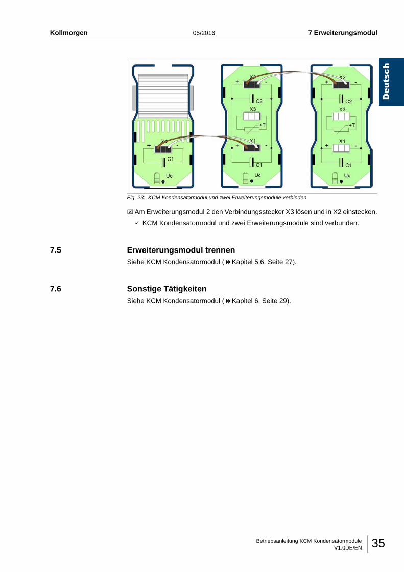
Fig. 23: KCM Kondensatormodul und zwei Erweiterungsmodule verbinden
⌧Am Erweiterungsmodul 2 den Verbindungsstecker X3 lösen und in X2 einstecken.
KCM Kondensatormodul und zwei Erweiterungsmodule sind verbunden.
7.5 Erweiterungsmodul trennenSiehe KCM Kondensatormodul ( Kapitel 5.6, Seite 27).
7.6 Sonstige TätigkeitenSiehe KCM Kondensatormodul ( Kapitel 6, Seite 29).
Betriebsanleitung KCM KondensatormoduleV1.0DE/EN36
Notizen... 05/2016 Kollmorgen
Deutsch
Instruction Manual KCM Capacitor ModulesV1.0DE/EN i
English
Kollmorgen 05/2016 Table of contents
1 Introduction1.1 Foreword . . . . . . . . . . . . . . . . . . . . . . . . . . . . . . . . . . . . . . . . . . . . . . . . . . . . . . . . . . . . . . . . . . 11.2 Environmental protection. . . . . . . . . . . . . . . . . . . . . . . . . . . . . . . . . . . . . . . . . . . . . . . . . . . . . . 11.3 Working with this Instruction Manual . . . . . . . . . . . . . . . . . . . . . . . . . . . . . . . . . . . . . . . . . . . . . 11.3.1 Target group . . . . . . . . . . . . . . . . . . . . . . . . . . . . . . . . . . . . . . . . . . . . . . . . . . . . . . . . . . . . . . . 11.3.2 Basic information . . . . . . . . . . . . . . . . . . . . . . . . . . . . . . . . . . . . . . . . . . . . . . . . . . . . . . . . . . . . 21.3.3 Abbreviations. . . . . . . . . . . . . . . . . . . . . . . . . . . . . . . . . . . . . . . . . . . . . . . . . . . . . . . . . . . . . . . 21.3.4 Symbols used in the text . . . . . . . . . . . . . . . . . . . . . . . . . . . . . . . . . . . . . . . . . . . . . . . . . . . . . . 31.3.5 Definitions . . . . . . . . . . . . . . . . . . . . . . . . . . . . . . . . . . . . . . . . . . . . . . . . . . . . . . . . . . . . . . . . . 3
2 Description of the device2.1 Intended use . . . . . . . . . . . . . . . . . . . . . . . . . . . . . . . . . . . . . . . . . . . . . . . . . . . . . . . . . . . . . . . 52.2 Applied guidelines . . . . . . . . . . . . . . . . . . . . . . . . . . . . . . . . . . . . . . . . . . . . . . . . . . . . . . . . . . . 52.3 Type designation . . . . . . . . . . . . . . . . . . . . . . . . . . . . . . . . . . . . . . . . . . . . . . . . . . . . . . . . . . . . 62.4 Overview diagram . . . . . . . . . . . . . . . . . . . . . . . . . . . . . . . . . . . . . . . . . . . . . . . . . . . . . . . . . . . 72.5 Type plates . . . . . . . . . . . . . . . . . . . . . . . . . . . . . . . . . . . . . . . . . . . . . . . . . . . . . . . . . . . . . . . . 82.6 Labels on the housing . . . . . . . . . . . . . . . . . . . . . . . . . . . . . . . . . . . . . . . . . . . . . . . . . . . . . . . . 92.7 Ambient conditions . . . . . . . . . . . . . . . . . . . . . . . . . . . . . . . . . . . . . . . . . . . . . . . . . . . . . . . . . 102.8 Electrical supply data. . . . . . . . . . . . . . . . . . . . . . . . . . . . . . . . . . . . . . . . . . . . . . . . . . . . . . . . 102.9 Dimensions and weight . . . . . . . . . . . . . . . . . . . . . . . . . . . . . . . . . . . . . . . . . . . . . . . . . . . . . . 102.10 Noise emission . . . . . . . . . . . . . . . . . . . . . . . . . . . . . . . . . . . . . . . . . . . . . . . . . . . . . . . . . . . . 10
3 Basic safety instructions3.1 Personnel . . . . . . . . . . . . . . . . . . . . . . . . . . . . . . . . . . . . . . . . . . . . . . . . . . . . . . . . . . . . . . . . 113.2 The device . . . . . . . . . . . . . . . . . . . . . . . . . . . . . . . . . . . . . . . . . . . . . . . . . . . . . . . . . . . . . . . . 113.3 Requirements of Underwriters Laboratories (UL) . . . . . . . . . . . . . . . . . . . . . . . . . . . . . . . . . . 12
4 Transport / Storage / Installation4.1 Checking the delivery . . . . . . . . . . . . . . . . . . . . . . . . . . . . . . . . . . . . . . . . . . . . . . . . . . . . . . . 134.2 Transporting the KCM Capacitor Module . . . . . . . . . . . . . . . . . . . . . . . . . . . . . . . . . . . . . . . . 134.3 Storing the KCM Capacitor Module . . . . . . . . . . . . . . . . . . . . . . . . . . . . . . . . . . . . . . . . . . . . . 134.4 Unpacking the KCM Capacitor Module . . . . . . . . . . . . . . . . . . . . . . . . . . . . . . . . . . . . . . . . . . 134.5 Installing the KCM Capacitor Module . . . . . . . . . . . . . . . . . . . . . . . . . . . . . . . . . . . . . . . . . . . 144.6 Earthing the KCM Capacitor Module . . . . . . . . . . . . . . . . . . . . . . . . . . . . . . . . . . . . . . . . . . . . 15
5 Commissioning5.1 Connecting the KCM Capacitor Module . . . . . . . . . . . . . . . . . . . . . . . . . . . . . . . . . . . . . . . . . 165.1.1 Connecting KCM-S . . . . . . . . . . . . . . . . . . . . . . . . . . . . . . . . . . . . . . . . . . . . . . . . . . . . . . . . . 175.1.2 Connecting KCM-P . . . . . . . . . . . . . . . . . . . . . . . . . . . . . . . . . . . . . . . . . . . . . . . . . . . . . . . . . 205.2 Connecting two or more KCM Capacitor Moduless in parallel . . . . . . . . . . . . . . . . . . . . . . . . 215.3 Connecting two or more applications with a DC link system
to one KCM Capacitor Module . . . . . . . . . . . . . . . . . . . . . . . . . . . . . . . . . . . . . . . . . . . . . . . . 225.4 Connecting the RS422 communication interface . . . . . . . . . . . . . . . . . . . . . . . . . . . . . . . . . . 235.5 Connecting the monitoring interface (depending on device) . . . . . . . . . . . . . . . . . . . . . . . . . . 245.6 Disconnecting the KCM Capacitor Module . . . . . . . . . . . . . . . . . . . . . . . . . . . . . . . . . . . . . . . 275.7 Conditioning the KCM Capacitor Module . . . . . . . . . . . . . . . . . . . . . . . . . . . . . . . . . . . . . . . . 28
6 Other tasks6.1 Cleaning the KCM Capacitor Module . . . . . . . . . . . . . . . . . . . . . . . . . . . . . . . . . . . . . . . . . . . 296.2 Maintenance of the KCM Capacitor Module . . . . . . . . . . . . . . . . . . . . . . . . . . . . . . . . . . . . . . 296.3 Repairing KCM Capacitor Modules . . . . . . . . . . . . . . . . . . . . . . . . . . . . . . . . . . . . . . . . . . . . . 306.4 Disposing of an KCM Capacitor Module . . . . . . . . . . . . . . . . . . . . . . . . . . . . . . . . . . . . . . . . . 30
Instruction Manual KCM Capacitor ModulesV1.0DE/ENii
Table of contents 05/2016 Kollmorgen
English
7 Extension module7.1 Technical data . . . . . . . . . . . . . . . . . . . . . . . . . . . . . . . . . . . . . . . . . . . . . . . . . . . . . . . . . . . . . 317.2 Transport / Storage / Installation. . . . . . . . . . . . . . . . . . . . . . . . . . . . . . . . . . . . . . . . . . . . . . . . 317.3 Connecting an extension module to the KCM Capacitor Module . . . . . . . . . . . . . . . . . . . . . . . 317.4 Connecting an additional extension module . . . . . . . . . . . . . . . . . . . . . . . . . . . . . . . . . . . . . . . 347.5 Disconnecting an extension module . . . . . . . . . . . . . . . . . . . . . . . . . . . . . . . . . . . . . . . . . . . . . 357.6 Other tasks . . . . . . . . . . . . . . . . . . . . . . . . . . . . . . . . . . . . . . . . . . . . . . . . . . . . . . . . . . . . . . . . 35
Instruction Manual KCM Capacitor ModulesV1.0DE/EN 1
Kollmorgen 05/2016 1 Introduction
English
1 INTRODUCTION
1.1 ForewordWe would like to thank you for the confidence you have placed in us by choosing the
pioneering energy technology produced by KOLLMORGEN Europe GmbH.
We thank you for your trust in us.
As a system provider, we set reliable standards in energy technology with our innova-
tive products. We aim for a sustainable corporate culture with our environmental man-
agement certified to EMAS III and our quality managements to DIN EN ISO 9001.
1.2 Environmental protection
Packaging We use environmentally friendly materials for our packaging which can be disposed
of via the local waste disposal system.
Equipment KOLLMORGEN Europe GmbH will take back faulty equipment or equipment which
is no longer in use.
1.3 Working with this Instruction Manual
1.3.1 Target groupThis Instruction Manual is aimed at qualified electricians who are to work with the
KCM Capacitor Module from KOLLMORGEN Europe GmbH in all phases of its serv-
ice life.
These include:
• KCM-S: Saves energy
• KCM-P: Power despite power failure
• KCM-E: Extension module
Instruction Manual KCM Capacitor ModulesV1.0DE/EN2
English
1 Introduction 05/2016 Kollmorgen
1.3.2 Basic informationThis Instruction Manual is divided into chapters.
Please note the following:
• Before using the KCM Condenser Module, read through this Instruction Manual
carefully and thoroughly. It is too late when the equipment is in use.
• Make an effort to understand it. Only then will you be able to operate the KCM Ca-
pacitor Module safely and as intended.
• Always follow the instructions given in the Instruction Manual.
• Keep this Instruction Manual close to the device.
Operators must know where it is kept.
1.3.3 Abbreviations
BGV Occupational health and safety regulationsEEPROM Electrical erasable programmable read only memory
Electrical erasable programmable read only memory (integrated circuit)EMC Electromagnetic CompatibilityEN European standardEU European UnionIT Isolated Terra (no connection to earth)KCM-E KOLLMORGEN Capacitor Module - Extension ModuleKCM-P KOLLMORGEN Capacitor Module - Energy SupplyKCM-S KOLLMORGEN Capacitor Module - Energy StorageLED Light-emitting diodePLC Programmable logic controlRFC Resonanz Frequenz CorrectionUL Underwriters Laboratories
(Independent company which investigates and certifies the safety of products)
Instruction Manual KCM Capacitor ModulesV1.0DE/EN 3
Kollmorgen 05/2016 1 Introduction
English
1.3.4 Symbols used in the text
Reference A reference to other pages in this Instruction Manual starts with the double arrow
symbol " ".
Action and reaction The symbol "⌧" indicates an action of the personnel, whilst the
symbol " " indicates the triggered reaction of the device.
For example:
⌧Switch on the main switch.
The lamp illuminates.
Image items and
relationship between
text and image
Important details are marked with numbers (e.g. q) in diagrams.
This is referred to in the text by this number after the associated detail.
1.3.5 Definitions
Person-Related
Warning Instructions
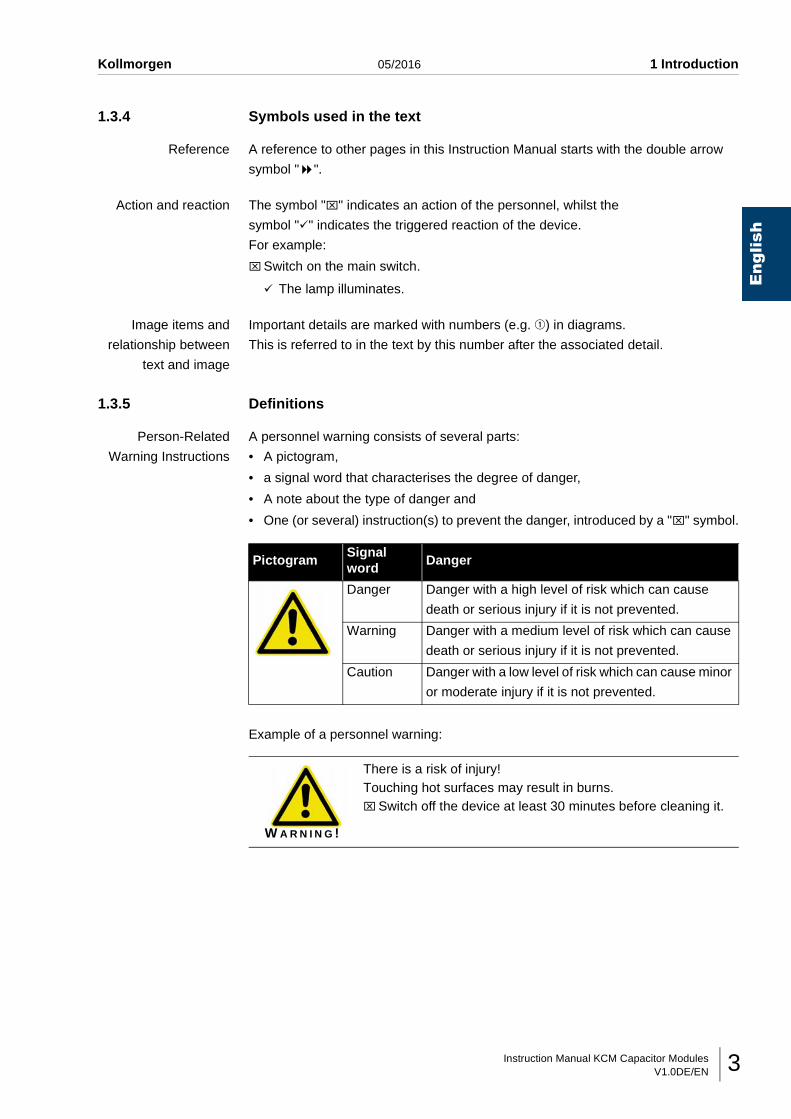
A personnel warning consists of several parts:
• A pictogram,
• a signal word that characterises the degree of danger,
• A note about the type of danger and
• One (or several) instruction(s) to prevent the danger, introduced by a "⌧" symbol.
Example of a personnel warning:
PictogramSignal word
Danger
Danger Danger with a high level of risk which can cause
death or serious injury if it is not prevented.
Warning Danger with a medium level of risk which can cause
death or serious injury if it is not prevented.
Caution Danger with a low level of risk which can cause minor
or moderate injury if it is not prevented.
W A R N I N G !
There is a risk of injury!Touching hot surfaces may result in burns.⌧Switch off the device at least 30 minutes before cleaning it.
Instruction Manual KCM Capacitor ModulesV1.0DE/EN4
English
1 Introduction 05/2016 Kollmorgen
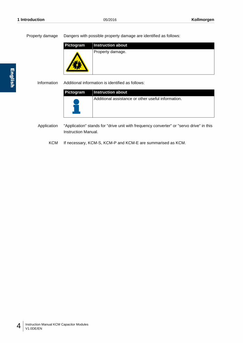
Property damage Dangers with possible property damage are identified as follows:
Information Additional information is identified as follows:
Application "Application" stands for "drive unit with frequency converter" or "servo drive" in this
Instruction Manual.
KCM If necessary, KCM-S, KCM-P and KCM-E are summarised as KCM.
Pictogram Instruction about
Property damage.
Pictogram Instruction about
Additional assistance or other useful information.
Instruction Manual KCM Capacitor ModulesV1.0DE/EN 5
Kollmorgen 05/2016 2 Description of the device
English
2 DESCRIPTION OF THE DEVICE
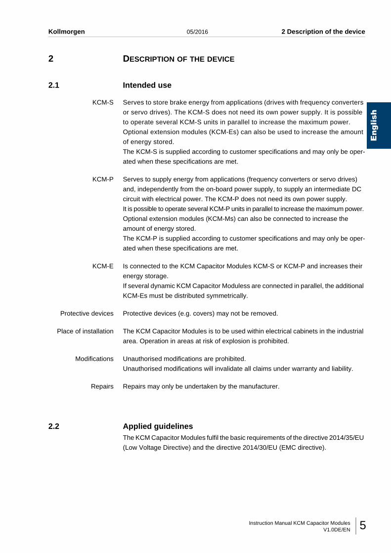
2.1 Intended use
KCM-S Serves to store brake energy from applications (drives with frequency converters
or servo drives). The KCM-S does not need its own power supply. It is possible
to operate several KCM-S units in parallel to increase the maximum power.
Optional extension modules (KCM-Es) can also be used to increase the amount
of energy stored.
The KCM-S is supplied according to customer specifications and may only be oper-
ated when these specifications are met.
KCM-P Serves to supply energy from applications (frequency converters or servo drives)
and, independently from the on-board power supply, to supply an intermediate DC
circuit with electrical power. The KCM-P does not need its own power supply.
It is possible to operate several KCM-P units in parallel to increase the maximum power.
Optional extension modules (KCM-Ms) can also be connected to increase the
amount of energy stored.
The KCM-P is supplied according to customer specifications and may only be oper-
ated when these specifications are met.
KCM-E Is connected to the KCM Capacitor Modules KCM-S or KCM-P and increases their
energy storage.
If several dynamic KCM Capacitor Moduless are connected in parallel, the additional
KCM-Es must be distributed symmetrically.
Protective devices Protective devices (e.g. covers) may not be removed.
Place of installation The KCM Capacitor Modules is to be used within electrical cabinets in the industrial
area. Operation in areas at risk of explosion is prohibited.
Modifications Unauthorised modifications are prohibited.
Unauthorised modifications will invalidate all claims under warranty and liability.
Repairs Repairs may only be undertaken by the manufacturer.
2.2 Applied guidelinesThe KCM Capacitor Modules fulfil the basic requirements of the directive 2014/35/EU
(Low Voltage Directive) and the directive 2014/30/EU (EMC directive).
Instruction Manual KCM Capacitor ModulesV1.0DE/EN6
English
2 Description of the device 05/2016 Kollmorgen
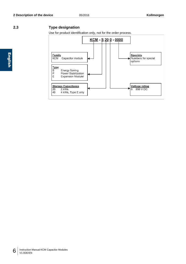
2.3 Type designationUse for product identification only, not for the order process.
Instruction Manual KCM Capacitor ModulesV1.0DE/EN 7
Kollmorgen 05/2016 2 Description of the device
English
2.4 Overview diagram
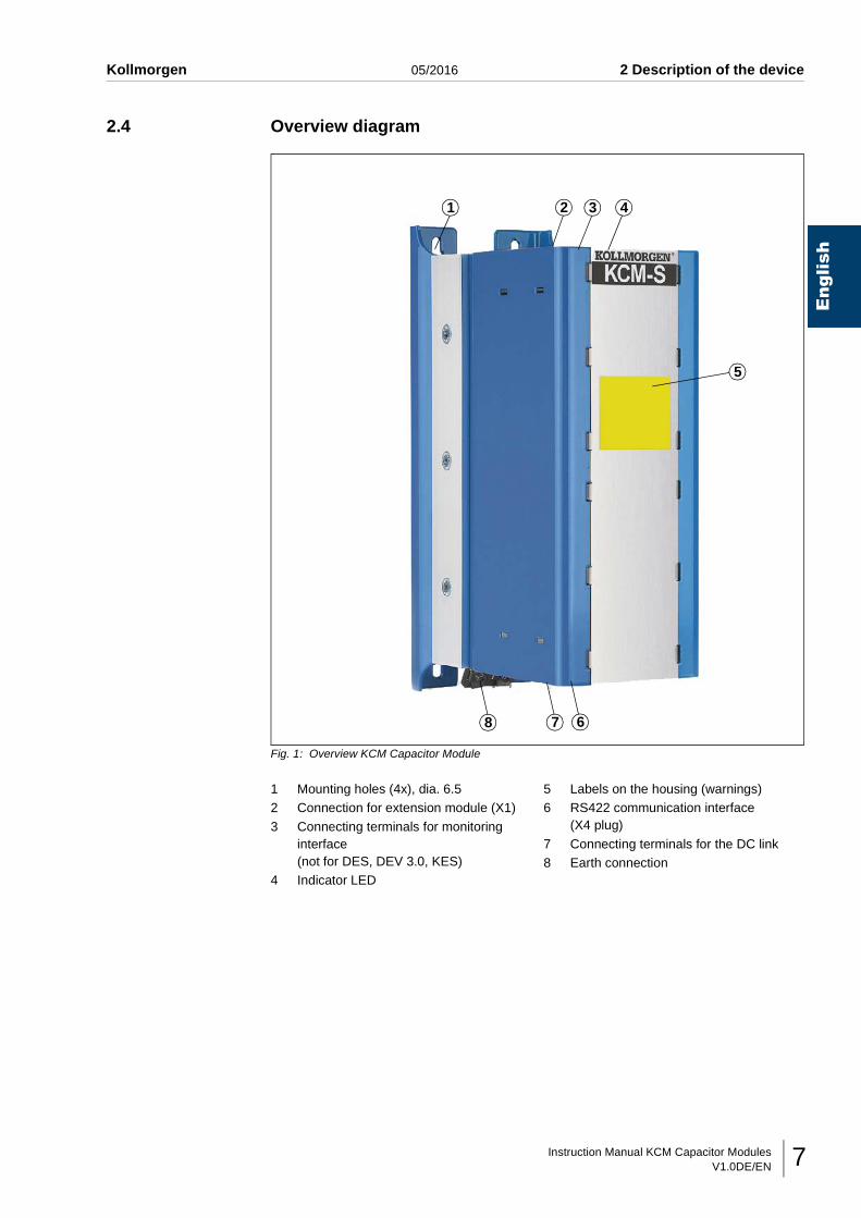
Fig. 1: Overview KCM Capacitor Module
1 Mounting holes (4x), dia. 6.52 Connection for extension module (X1)
3 Connecting terminals for monitoring interface (not for DES, DEV 3.0, KES)
4 Indicator LED
5 Labels on the housing (warnings)6 RS422 communication interface
(X4 plug)
7 Connecting terminals for the DC link8 Earth connection
1 2 3 4
5
678
Instruction Manual KCM Capacitor ModulesV1.0DE/EN8
English
2 Description of the device 05/2016 Kollmorgen
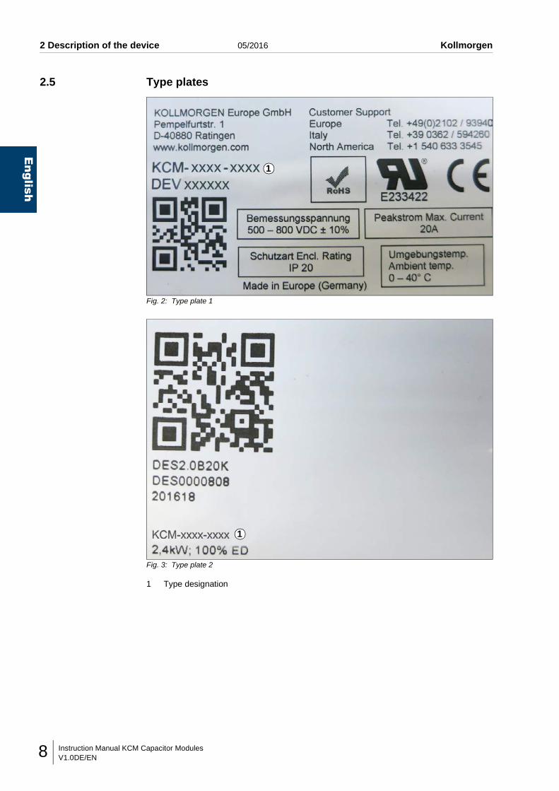
2.5 Type plates
Fig. 2: Type plate 1
Fig. 3: Type plate 2
1 Type designation
1
1
Instruction Manual KCM Capacitor ModulesV1.0DE/EN 9
Kollmorgen 05/2016 2 Description of the device
English
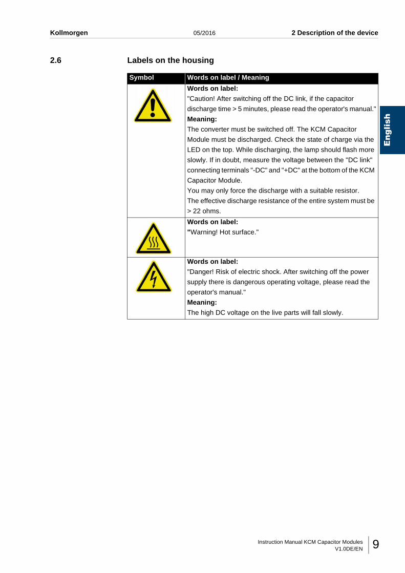
2.6 Labels on the housing
Symbol Words on label / Meaning
Words on label:
"Caution! After switching off the DC link, if the capacitor
discharge time > 5 minutes, please read the operator's manual."
Meaning:
The converter must be switched off. The KCM Capacitor
Module must be discharged. Check the state of charge via the
LED on the top. While discharging, the lamp should flash more
slowly. If in doubt, measure the voltage between the "DC link"
connecting terminals "-DC" and "+DC" at the bottom of the KCM
Capacitor Module.
You may only force the discharge with a suitable resistor.
The effective discharge resistance of the entire system must be
> 22 ohms.
Words on label:
"Warning! Hot surface."
Words on label:
"Danger! Risk of electric shock. After switching off the power
supply there is dangerous operating voltage, please read the
operator's manual."
Meaning:
The high DC voltage on the live parts will fall slowly.
Instruction Manual KCM Capacitor ModulesV1.0DE/EN10
English
2 Description of the device 05/2016 Kollmorgen
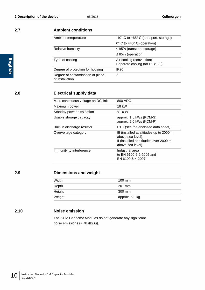
2.7 Ambient conditions
2.8 Electrical supply data
2.9 Dimensions and weight
2.10 Noise emission
The KCM Capacitor Modules do not generate any significant
noise emissions (< 70 dB(A)).
Ambient temperature -10° C to +65° C (transport, storage)
0° C to +40° C (operation)
Relative humidity ≤ 95% (transport, storage)
≤ 85% (operation)
Type of cooling Air cooling (convection)Separate cooling (for DEx 3.0)
Degree of protection for housing IP20
Degree of contamination at place of installation
2
Max. continuous voltage on DC link 800 VDC
Maximum power 18 kW
Standby power dissipation < 10 W
Usable storage capacity approx. 1.6 kWs (KCM-S)approx. 2.0 kWs (KCM-P)
Built-in discharge resistor PTC (see the enclosed data sheet)
Overvoltage category III (installed at altitudes up to 2000 m above sea level)II (installed at altitudes over 2000 m above sea level)
Immunity to interference Industrial areato EN 6100-6-2-2005 and EN 6100-6-4-2007
Width 100 mm
Depth 201 mm
Height 300 mm
Weight approx. 6.9 kg
Instruction Manual KCM Capacitor ModulesV1.0DE/EN 11
Kollmorgen 05/2016 3 Basic safety instructions
English
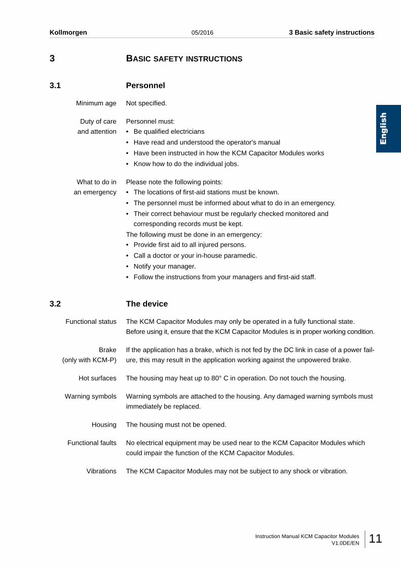
3 BASIC SAFETY INSTRUCTIONS
3.1 Personnel
Minimum age Not specified.
Duty of care
and attention
Personnel must:
• Be qualified electricians
• Have read and understood the operator's manual
• Have been instructed in how the KCM Capacitor Modules works
• Know how to do the individual jobs.
What to do in
an emergency
Please note the following points:
• The locations of first-aid stations must be known.
• The personnel must be informed about what to do in an emergency.
• Their correct behaviour must be regularly checked monitored and
corresponding records must be kept.
The following must be done in an emergency:
• Provide first aid to all injured persons.
• Call a doctor or your in-house paramedic.
• Notify your manager.
• Follow the instructions from your managers and first-aid staff.
3.2 The device
Functional status The KCM Capacitor Modules may only be operated in a fully functional state.
Before using it, ensure that the KCM Capacitor Modules is in proper working condition.
Brake
(only with KCM-P)
If the application has a brake, which is not fed by the DC link in case of a power fail-
ure, this may result in the application working against the unpowered brake.
Hot surfaces The housing may heat up to 80° C in operation. Do not touch the housing.
Warning symbols Warning symbols are attached to the housing. Any damaged warning symbols must
immediately be replaced.
Housing The housing must not be opened.
Functional faults No electrical equipment may be used near to the KCM Capacitor Modules which
could impair the function of the KCM Capacitor Modules.
Vibrations The KCM Capacitor Modules may not be subject to any shock or vibration.
Instruction Manual KCM Capacitor ModulesV1.0DE/EN12
English
3 Basic safety instructions 05/2016 Kollmorgen
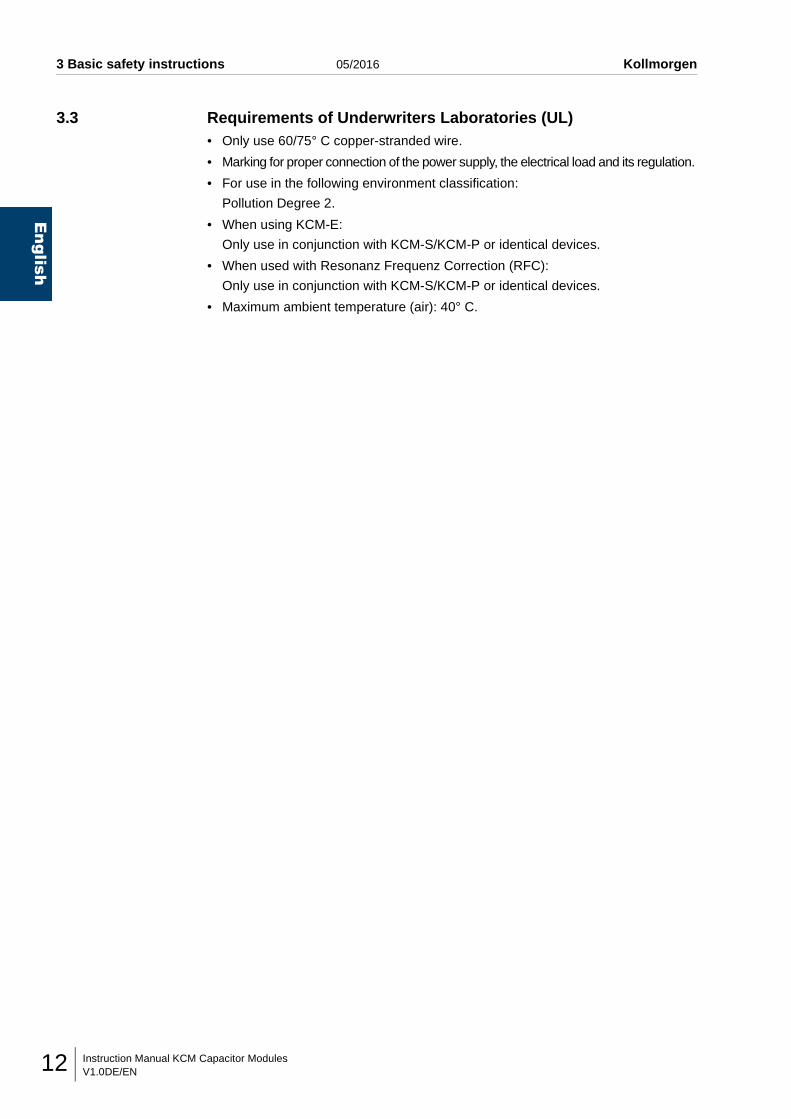
3.3 Requirements of Underwriters Laboratories (UL)• Only use 60/75° C copper-stranded wire.
• Marking for proper connection of the power supply, the electrical load and its regulation.
• For use in the following environment classification:
Pollution Degree 2.
• When using KCM-E:
Only use in conjunction with KCM-S/KCM-P or identical devices.
• When used with Resonanz Frequenz Correction (RFC):
Only use in conjunction with KCM-S/KCM-P or identical devices.
• Maximum ambient temperature (air): 40° C.
Instruction Manual KCM Capacitor ModulesV1.0DE/EN 13
Kollmorgen 05/2016 4 Transport / Storage / Installation
English
4 TRANSPORT / STORAGE / INSTALLATION
4.1 Checking the deliveryThe KCM Capacitor Modules leave the factory in a tested and perfect condition.
Special packaging, consisting of cardboard, corrugated cardboard and protective
film, ensures safe transport.
There is a packing label on the outside of the packaging. This contains instructions
for transport, storage and proper handling which must be followed.
Any transport damage is the responsibility of the transport company.
Scope of delivery • 1 × KCM Capacitor Module
• 1 × Instruction Manual KCM Capacitor Module
• 1 × Data sheet for the built-in brake resistor (specific to order)
Please see the delivery note for the exact scope of delivery.
Checking the delivery: ⌧Check the packaging for damage.
⌧ Immediately notify the transport company about any damage to the packaging
and/or the KCM Capacitor Module.
The transport company must receive a written damage report within 7 days.
4.2 Transporting the KCM Capacitor Module⌧Transport the KCM Capacitor Module to where it is to be installed in its original
packaging.
⌧Avoid heavy vibrations and hard knocks.
4.3 Storing the KCM Capacitor ModuleThe KCM Capacitor Module must be stored in clean, dry areas.
Temperatures between -10° C and 65° C are permissible.
Any temperature fluctuations must not exceed 30 K per hour.
4.4 Unpacking the KCM Capacitor Module⌧Carefully remove the KCM Capacitor Module from its packaging.
⌧Check that nothing is missing and that it is undamaged.
⌧Dispose of the packaging in accordance with local regulations for cardboard boxes
and recyclable materials.
Instruction Manual KCM Capacitor ModulesV1.0DE/EN14
English
4 Transport / Storage / Installation 05/2016 Kollmorgen
4.5 Installing the KCM Capacitor Module
Basic information • The KCM Capacitor Module is intended to be installed in an electrical cabinet.
• The KCM Capacitor Module must be protected against penetration of foreign bod-
ies in the cabinet.
• It must be installed directly onto a mounting area in the cabinet or onto a subframe
provided by KOLLMORGEN Europe GmbH for this purpose.
• The KCM Capacitor Module needs to be installed right next to the application (fre-
quency converter, servo controller) on account of the length of the connecting ca-
ble (max. 1 m).
Spacing During installation, the following spacings to other modules must be maintained:
• At the side: at least 20 mm.
• Above and below: at least 100 mm.
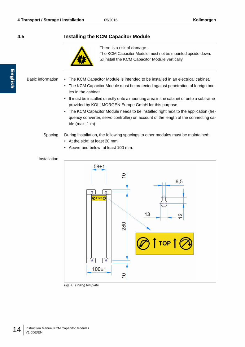
Installation
Fig. 4: Drilling template
There is a risk of damage.The KCM Capacitor Module must not be mounted upside down.⌧ Install the KCM Capacitor Module vertically.
Instruction Manual KCM Capacitor ModulesV1.0DE/EN 15
Kollmorgen 05/2016 4 Transport / Storage / Installation
English
⌧ Install the KCM Capacitor Module according to the drilling template, vertically,
using four bolts (M6) as follows.
Screw in the two top bolts first of all, then hook in the KCM Capacitor Module
and then screw in the two bottom bolts.
The power connection is at the bottom.
⌧Tighten all bolts by hand and check for firm seating.
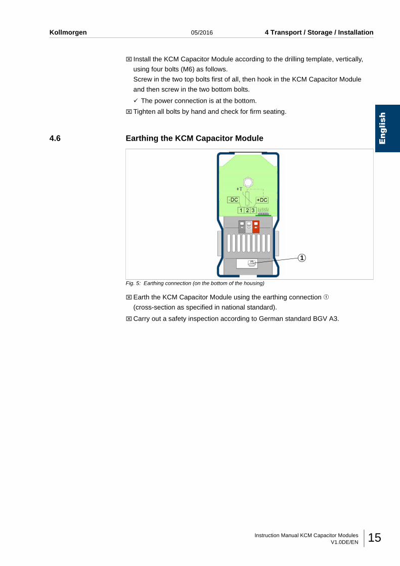
4.6 Earthing the KCM Capacitor Module
Fig. 5: Earthing connection (on the bottom of the housing)
⌧Earth the KCM Capacitor Module using the earthing connection q
(cross-section as specified in national standard).
⌧Carry out a safety inspection according to German standard BGV A3.
1
Instruction Manual KCM Capacitor ModulesV1.0DE/EN16
English
5 Commissioning 05/2016 Kollmorgen
5 COMMISSIONING
5.1 Connecting the KCM Capacitor ModuleThe following always applies:
• The places of operation must be dry and dust-free.
• The air supplied must not contain any electrically-conductive dust, gas or vapour
which could impair functionality. Corresponding remedial measures must be taken
if necessary.
• The KCM Capacitor Module may only be operated in ambient temperatures from
0 - 40 °C.
• The KCM Capacitor Module may only be operated in connection with an applica-
tion which has direct access to the intermediate circuit capacity.
• The connecting wires (cross-section to comply with your national standards) be-
tween the KCM Capacitor Module and the application must not be longer than 1.0
m, must be laid as a twisted pair and must be proof against short-circuits.
• If the connecting line is more than 0.5 m or if you have increased demands on the
electromagnetic compatibility, you will find important information in the Kollmorgen
product WIKI on Page
"KCM at increased EMC requirements".
(http://wiki-kollmorgen.eu/wiki/tiki-index.php?page=KCM+with+high+EMC+re-
quirements)
D A N G E R !
There is a danger of fatal injury.Do not use in the wrong area.⌧ It is not permitted to use the KCM Capacitor Module for IT
networks.IT (Isolated Terra) = floating supply
W A R N I N G !
There is a risk of injury!The housing may heat up to 80° C in operation.⌧ If you have to work on the KCM Capacitor Module, wear heat-
resistant safety gloves.
Instruction Manual KCM Capacitor ModulesV1.0DE/EN 17
Kollmorgen 05/2016 5 Commissioning
English
5.1.1 Connecting KCM-S
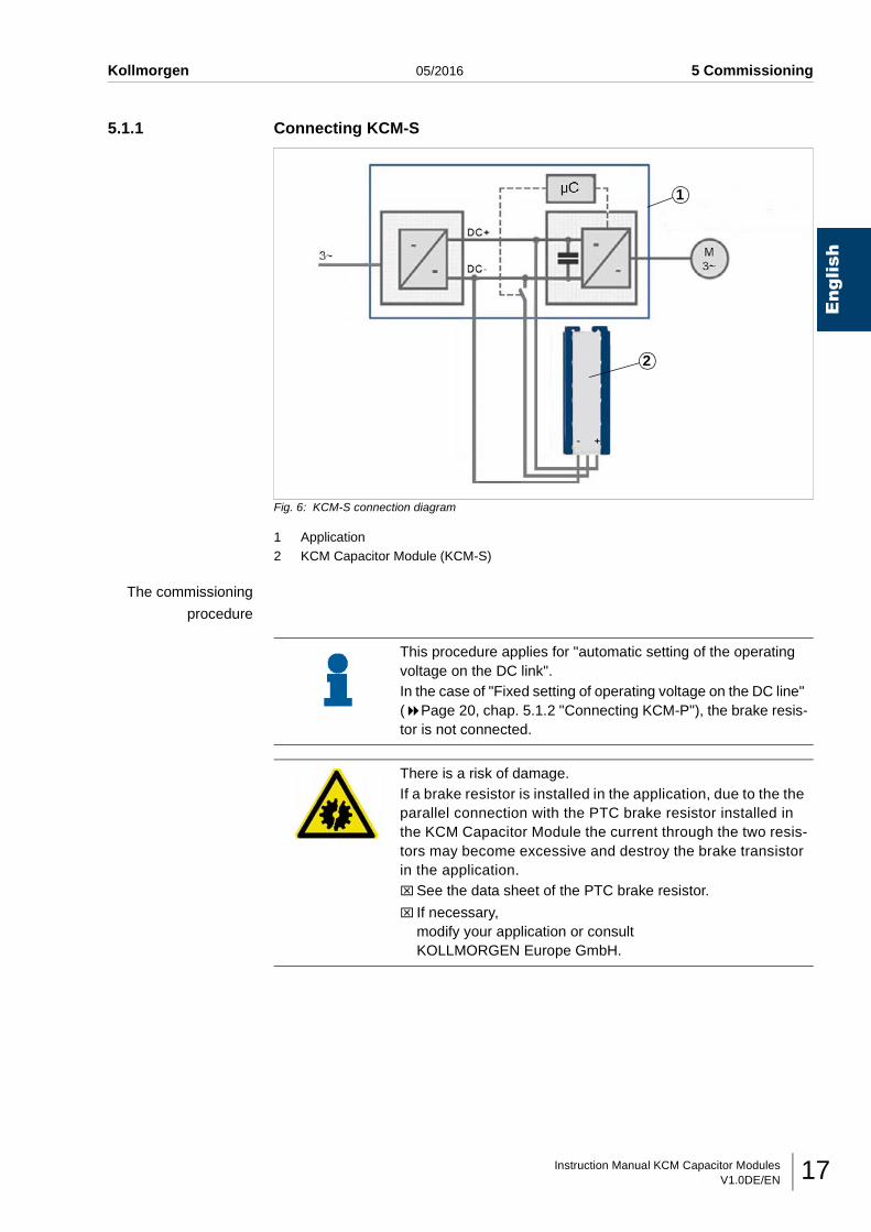
Fig. 6: KCM-S connection diagram
1 Application2 KCM Capacitor Module (KCM-S)
The commissioning
procedure
1
2
This procedure applies for "automatic setting of the operating voltage on the DC link".In the case of "Fixed setting of operating voltage on the DC line" ( Page 20, chap. 5.1.2 "Connecting KCM-P"), the brake resis-tor is not connected.
There is a risk of damage.If a brake resistor is installed in the application, due to the the parallel connection with the PTC brake resistor installed in the KCM Capacitor Module the current through the two resis-tors may become excessive and destroy the brake transistor in the application.⌧See the data sheet of the PTC brake resistor.
⌧ If necessary, modify your application or consult KOLLMORGEN Europe GmbH.
Instruction Manual KCM Capacitor ModulesV1.0DE/EN18
English
5 Commissioning 05/2016 Kollmorgen
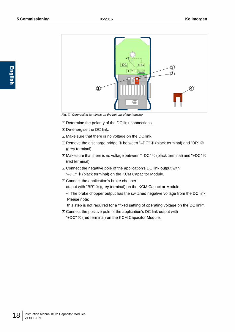
Fig. 7: Connecting terminals on the bottom of the housing
⌧Determine the polarity of the DC link connections.
⌧De-energise the DC link.
⌧Make sure that there is no voltage on the DC link.
⌧Remove the discharge bridge r between "–DC" q (black terminal) and "BR" w
(grey terminal).
⌧Make sure that there is no voltage between "–DC" q (black terminal) and "+DC" e
(red terminal).
⌧Connect the negative pole of the application's DC link output with
"–DC" q (black terminal) on the KCM Capacitor Module.
⌧Connect the application's brake chopper
output with "BR" w (grey terminal) on the KCM Capacitor Module.
The brake chopper output has the switched negative voltage from the DC link.
Please note:
this step is not required for a "fixed setting of operating voltage on the DC link".
⌧Connect the positive pole of the application's DC link output with
"+DC" e (red terminal) on the KCM Capacitor Module.
1
2
3
4
Instruction Manual KCM Capacitor ModulesV1.0DE/EN 19
Kollmorgen 05/2016 5 Commissioning
English
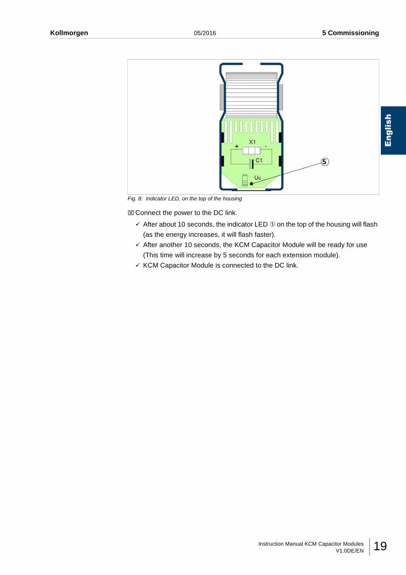
Fig. 8: Indicator LED, on the top of the housing
⌧Connect the power to the DC link.
After about 10 seconds, the indicator LED t on the top of the housing will flash
(as the energy increases, it will flash faster).
After another 10 seconds, the KCM Capacitor Module will be ready for use
(This time will increase by 5 seconds for each extension module).
KCM Capacitor Module is connected to the DC link.
5
Instruction Manual KCM Capacitor ModulesV1.0DE/EN20
English
5 Commissioning 05/2016 Kollmorgen
5.1.2 Connecting KCM-P
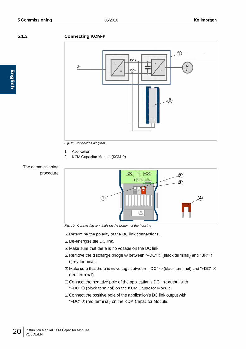
Fig. 9: Connection diagram
1 Application2 KCM Capacitor Module (KCM-P)
The commissioning
procedure
Fig. 10: Connecting terminals on the bottom of the housing
⌧Determine the polarity of the DC link connections.
⌧De-energise the DC link.
⌧Make sure that there is no voltage on the DC link.
⌧Remove the discharge bridge r between "–DC" q (black terminal) and "BR" w
(grey terminal).
⌧Make sure that there is no voltage between "–DC" q (black terminal) and "+DC" e
(red terminal).
⌧Connect the negative pole of the application's DC link output with
"–DC" q (black terminal) on the KCM Capacitor Module.
⌧Connect the positive pole of the application's DC link output with
"+DC" e (red terminal) on the KCM Capacitor Module.
1
2
1
2
3
4
Instruction Manual KCM Capacitor ModulesV1.0DE/EN 21
Kollmorgen 05/2016 5 Commissioning
English
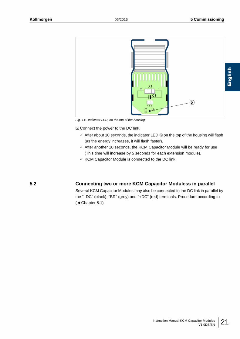
Fig. 11: Indicator LED, on the top of the housing
⌧Connect the power to the DC link.
After about 10 seconds, the indicator LED t on the top of the housing will flash
(as the energy increases, it will flash faster).
After another 10 seconds, the KCM Capacitor Module will be ready for use
(This time will increase by 5 seconds for each extension module).
KCM Capacitor Module is connected to the DC link.
5.2 Connecting two or more KCM Capacitor Moduless in parallelSeveral KCM Capacitor Modules may also be connected to the DC link in parallel by
the "–DC" (black), "BR" (grey) and "+DC" (red) terminals. Procedure according to
( Chapter 5.1).
5
Instruction Manual KCM Capacitor ModulesV1.0DE/EN22
English
5 Commissioning 05/2016 Kollmorgen
5.3 Connecting two or more applications with a DC link systemto one KCM Capacitor Module
Only one application has a brake resistor
⌧Connect the KCM Capacitor Module to this application.
⌧Connect the brake resistor line to this application.
Several applications have a brake resistor and it is certain
that all applications always brake at the same time
⌧Connect the KCM Capacitor Module to any application.
⌧Connect the brake resistor line to the same application.
Several applications have a brake resistor and it is not certain
that all applications always brake at the same time
(only for KCM Capacitor Module with a fixed setting for the working voltage on
the DC link)
⌧Connect the KCM Capacitor Module to any application.
⌧Do not connect the brake resistor line (fixed default setting).
Instruction Manual KCM Capacitor ModulesV1.0DE/EN 23
Kollmorgen 05/2016 5 Commissioning
English
5.4 Connecting the RS422 communication interface
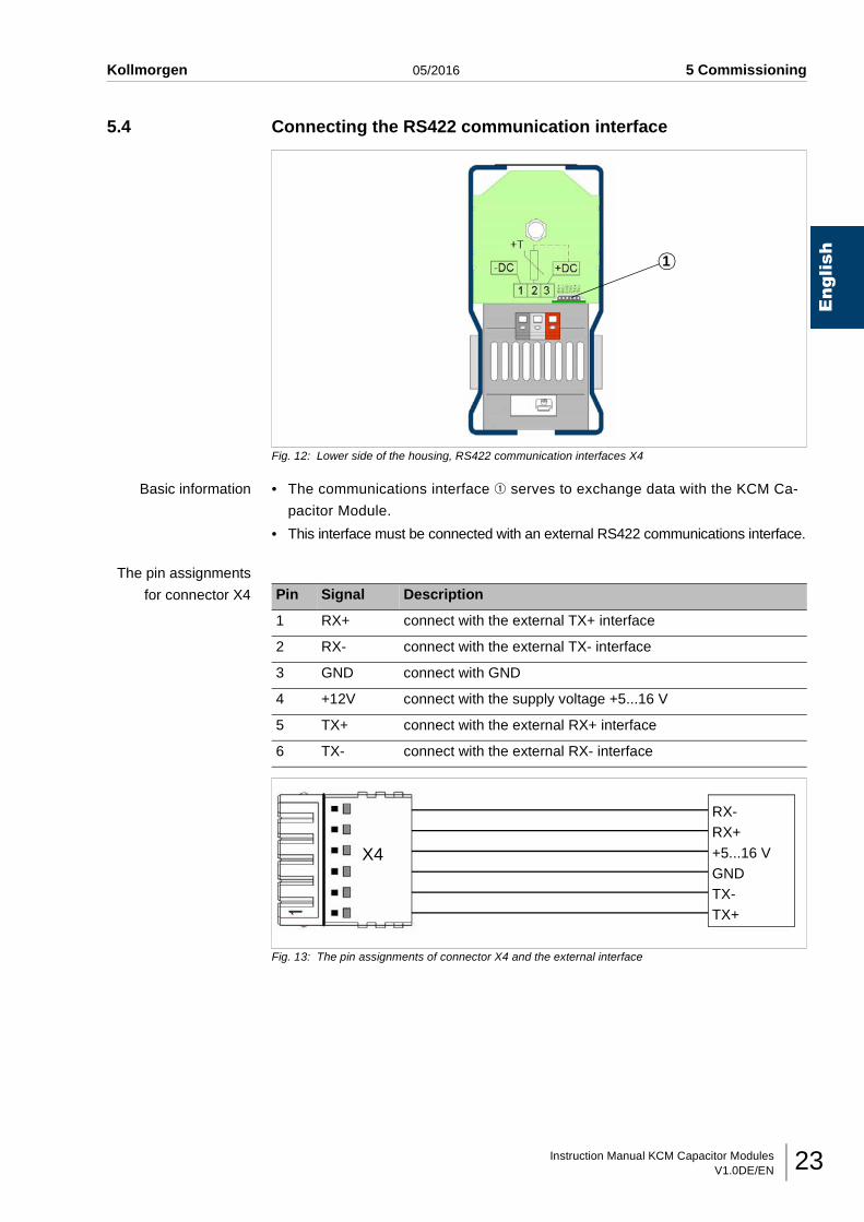
Fig. 12: Lower side of the housing, RS422 communication interfaces X4
Basic information • The communications interface q serves to exchange data with the KCM Ca-
pacitor Module.
• This interface must be connected with an external RS422 communications interface.
The pin assignments
for connector X4
Fig. 13: The pin assignments of connector X4 and the external interface
1
Pin Signal Description
1 RX+ connect with the external TX+ interface
2 RX- connect with the external TX- interface
3 GND connect with GND
4 +12V connect with the supply voltage +5...16 V
5 TX+ connect with the external RX+ interface
6 TX- connect with the external RX- interface
X4
RX-RX++5...16 VGNDTX-TX+
Instruction Manual KCM Capacitor ModulesV1.0DE/EN24
English
5 Commissioning 05/2016 Kollmorgen
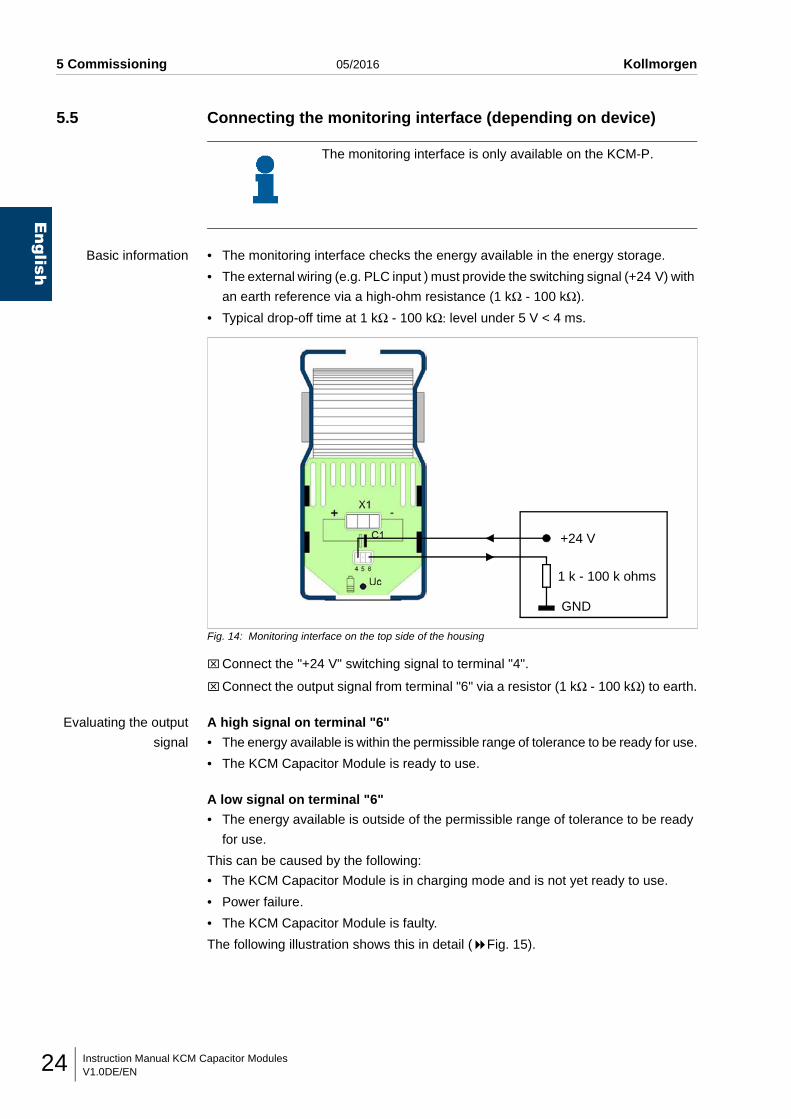
5.5 Connecting the monitoring interface (depending on device)
Basic information • The monitoring interface checks the energy available in the energy storage.
• The external wiring (e.g. PLC input ) must provide the switching signal (+24 V) with
an earth reference via a high-ohm resistance (1 kΩ - 100 kΩ).
• Typical drop-off time at 1 kΩ - 100 kΩ: level under 5 V < 4 ms.
Fig. 14: Monitoring interface on the top side of the housing
⌧Connect the "+24 V" switching signal to terminal "4".
⌧Connect the output signal from terminal "6" via a resistor (1 kΩ - 100 kΩ) to earth.
Evaluating the output
signal
A high signal on terminal "6"
• The energy available is within the permissible range of tolerance to be ready for use.
• The KCM Capacitor Module is ready to use.
A low signal on terminal "6"
• The energy available is outside of the permissible range of tolerance to be ready
for use.
This can be caused by the following:
• The KCM Capacitor Module is in charging mode and is not yet ready to use.
• Power failure.
• The KCM Capacitor Module is faulty.
The following illustration shows this in detail ( Fig. 15).
The monitoring interface is only available on the KCM-P.
+24 V
1 k - 100 k ohms
GND
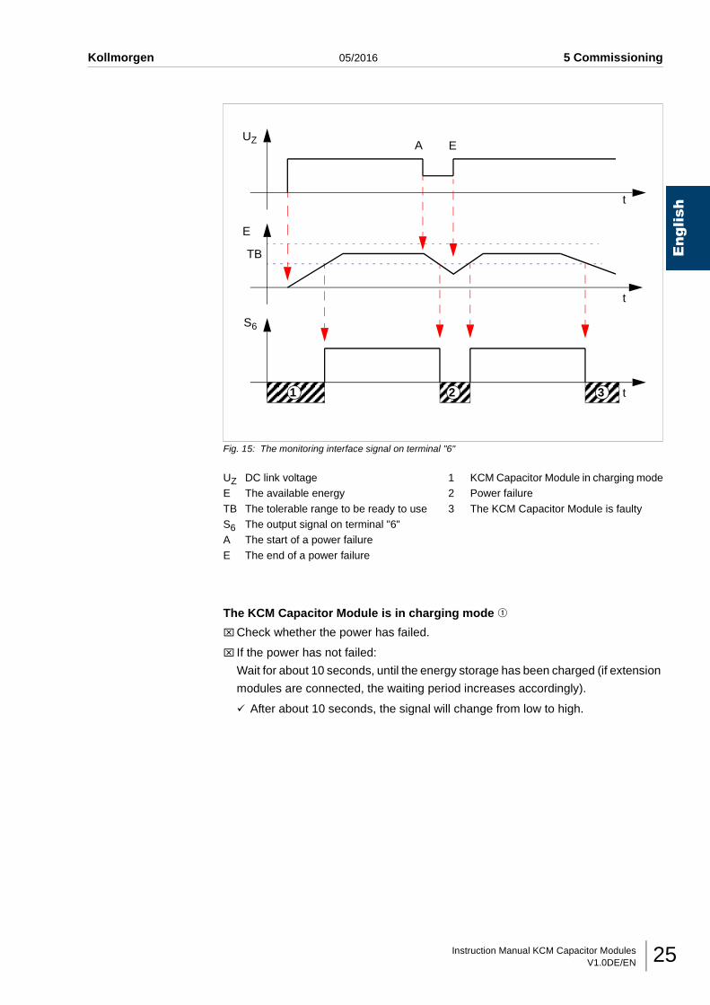
Instruction Manual KCM Capacitor ModulesV1.0DE/EN 25
Kollmorgen 05/2016 5 Commissioning
English
Fig. 15: The monitoring interface signal on terminal "6"
The KCM Capacitor Module is in charging mode q
⌧Check whether the power has failed.
⌧ If the power has not failed:
Wait for about 10 seconds, until the energy storage has been charged (if extension
modules are connected, the waiting period increases accordingly).
After about 10 seconds, the signal will change from low to high.
UZ DC link voltageE The available energy
TB The tolerable range to be ready to useS6 The output signal on terminal "6"A The start of a power failure
E The end of a power failure
1 KCM Capacitor Module in charging mode2 Power failure
3 The KCM Capacitor Module is faulty
AUZ
E
t
t
S6
TB
E
1 2 3
t
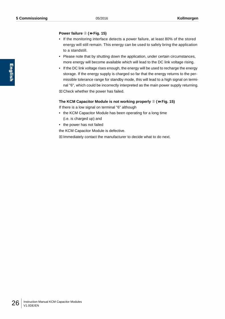
Instruction Manual KCM Capacitor ModulesV1.0DE/EN26
English
5 Commissioning 05/2016 Kollmorgen
Power failure w ( Fig. 15)
• If the monitoring interface detects a power failure, at least 80% of the stored
energy will still remain. This energy can be used to safely bring the application
to a standstill.
• Please note that by shutting down the application, under certain circumstances,
more energy will become available which will lead to the DC link voltage rising.
• If the DC link voltage rises enough, the energy will be used to recharge the energy
storage. If the energy supply is charged so far that the energy returns to the per-
missible tolerance range for standby mode, this will lead to a high signal on termi-
nal "6", which could be incorrectly interpreted as the main power supply returning.
⌧Check whether the power has failed.
The KCM Capacitor Module is not working properly e ( Fig. 15)
If there is a low signal on terminal "6" although
• the KCM Capacitor Module has been operating for a long time
(i.e. is charged up) and
• the power has not failed
the KCM Capacitor Module is defective.
⌧ Immediately contact the manufacturer to decide what to do next.
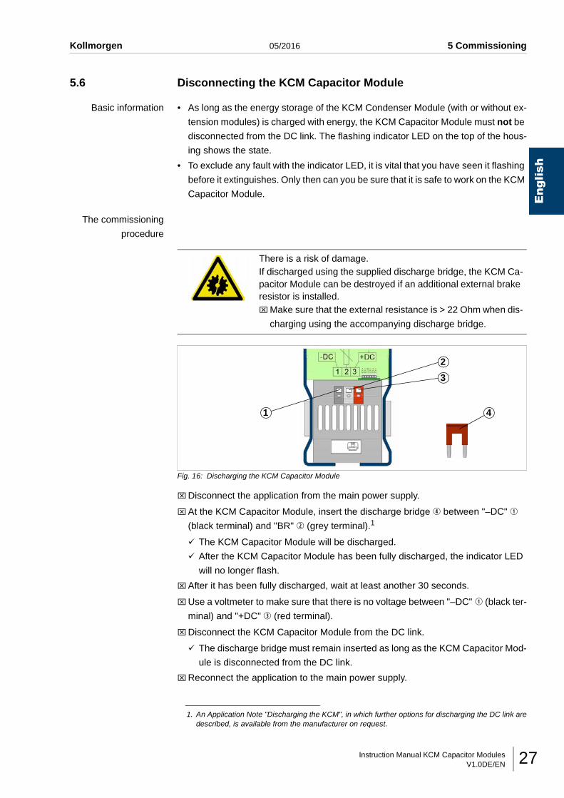
Instruction Manual KCM Capacitor ModulesV1.0DE/EN 27
Kollmorgen 05/2016 5 Commissioning
English
5.6 Disconnecting the KCM Capacitor Module
Basic information • As long as the energy storage of the KCM Condenser Module (with or without ex-
tension modules) is charged with energy, the KCM Capacitor Module must not be
disconnected from the DC link. The flashing indicator LED on the top of the hous-
ing shows the state.
• To exclude any fault with the indicator LED, it is vital that you have seen it flashing
before it extinguishes. Only then can you be sure that it is safe to work on the KCM
Capacitor Module.
The commissioning
procedure
Fig. 16: Discharging the KCM Capacitor Module
⌧Disconnect the application from the main power supply.
⌧At the KCM Capacitor Module, insert the discharge bridge r between "–DC" q
(black terminal) and "BR" w (grey terminal).1
The KCM Capacitor Module will be discharged.
After the KCM Capacitor Module has been fully discharged, the indicator LED
will no longer flash.
⌧After it has been fully discharged, wait at least another 30 seconds.
⌧Use a voltmeter to make sure that there is no voltage between "–DC" q (black ter-
minal) and "+DC" e (red terminal).
⌧Disconnect the KCM Capacitor Module from the DC link.
The discharge bridge must remain inserted as long as the KCM Capacitor Mod-
ule is disconnected from the DC link.
⌧Reconnect the application to the main power supply.
There is a risk of damage.If discharged using the supplied discharge bridge, the KCM Ca-pacitor Module can be destroyed if an additional external brake resistor is installed.⌧Make sure that the external resistance is > 22 Ohm when dis-
charging using the accompanying discharge bridge.
1. An Application Note "Discharging the KCM", in which further options for discharging the DC link aredescribed, is available from the manufacturer on request.
1
2
3
4
Instruction Manual KCM Capacitor ModulesV1.0DE/EN28
English
5 Commissioning 05/2016 Kollmorgen
5.7 Conditioning the KCM Capacitor Module
Basic information • If the KCM Capacitor Module has been de-energised for more than one year, it
must be formed. Failure to do this may result in the KCM Capacitor Module being
damaged when the main supply voltage is switched on.
• The date of manufacture is on the model plate ( Page 8, Fig. 2).
• During forming, the KCM Capacitor Module is connected to the DC link but is not
ready for use.
Fig. 17: Conditioning time, depending on the voltage-free period
The commissioning
procedure
⌧Connect the KCM Capacitor Module to the DC link
( Chapter 5.1, page 16).
The KCM Capacitor Module will be conditioned (charged up).
⌧Wait for the duration of the conditioning period which corresponds to the length of
the voltage-free period ( Fig. 17).
The application can then be enabled again.
Voltage-free time [years]
Conditioning
5
4
3
2
1
1 2 3 4 5
time [h]
Instruction Manual KCM Capacitor ModulesV1.0DE/EN 29
Kollmorgen 05/2016 6 Other tasks
English
6 OTHER TASKS
6.1 Cleaning the KCM Capacitor Module
⌧Only use alcohol-free cleaning agents.
⌧Only clean the KCM Capacitor Module when it is completely de-energised.
⌧ Just wipe down the KCM Capacitor Module with a damp cloth.
6.2 Maintenance of the KCM Capacitor ModuleThe KCM Capacitor Module requires no maintenance.
If the KCM Capacitor Module has been de-energised for more than 1 year, it must be
formed ( Page 28, chap. 5.7 "Conditioning the KCM Capacitor Module").
D A N G E R !
There is a danger of fatal injury.Cleaning fluid can penetrate the housing and cause a short-circuit.⌧Only clean the housing when the unit is completely de-
energised.
D A N G E R !
There is a danger of fatal injury.Cleaning agents which contain alcohol can cause explosions.⌧Only use alcohol-free cleaning agents.
W A R N I N G !
There is a risk of injury!Touching hot surfaces may result in burns.⌧Switch off the KCM Capacitor Module for at least 30 minutes
before cleaning it.
There is a risk of damage.Cleaning fluid can penetrate the housing and cause a short-circuit or damage components.⌧ Just wipe down the housing with a damp cloth.

Instruction Manual KCM Capacitor ModulesV1.0DE/EN30
English
6 Other tasks 05/2016 Kollmorgen
6.3 Repairing KCM Capacitor Modules
A faulty KCM Capacitor Module can only be repaired by its manufacturer.
6.4 Disposing of an KCM Capacitor Module⌧Disconnect the KCM Capacitor Module
( Page 27, chap. 5.6 "Disconnecting the KCM Capacitor Module").
⌧Remove the KCM Capacitor Module.
⌧Return the KCM Capacitor Module to the manufacturer.
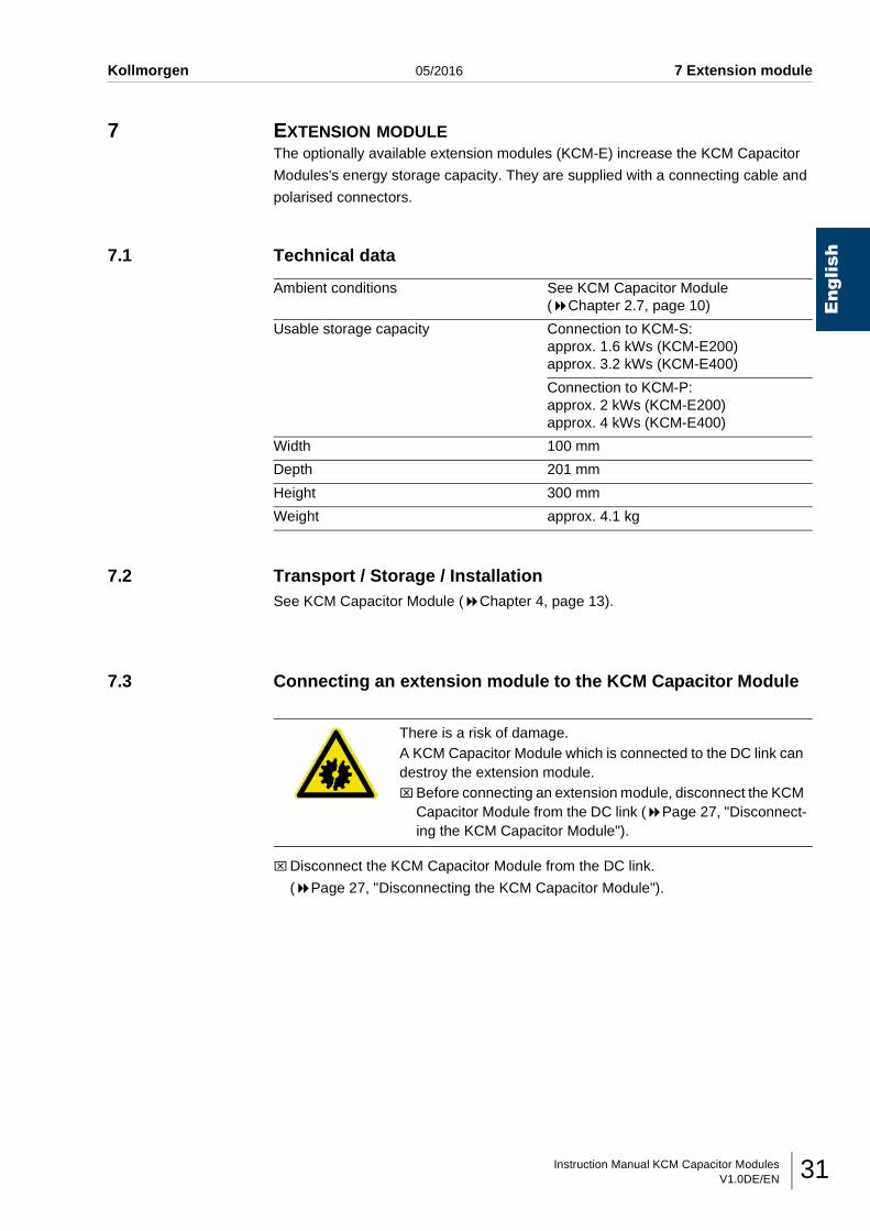
Instruction Manual KCM Capacitor ModulesV1.0DE/EN 31
Kollmorgen 05/2016 7 Extension module
English
7 EXTENSION MODULEThe optionally available extension modules (KCM-E) increase the KCM Capacitor
Modules's energy storage capacity. They are supplied with a connecting cable and
polarised connectors.
7.1 Technical data
7.2 Transport / Storage / InstallationSee KCM Capacitor Module ( Chapter 4, page 13).
7.3 Connecting an extension module to the KCM Capacitor Module
⌧Disconnect the KCM Capacitor Module from the DC link.
( Page 27, "Disconnecting the KCM Capacitor Module").
Ambient conditions See KCM Capacitor Module( Chapter 2.7, page 10)
Usable storage capacity Connection to KCM-S:approx. 1.6 kWs (KCM-E200)approx. 3.2 kWs (KCM-E400)
Connection to KCM-P:approx. 2 kWs (KCM-E200)approx. 4 kWs (KCM-E400)
Width 100 mm
Depth 201 mm
Height 300 mm
Weight approx. 4.1 kg
There is a risk of damage.A KCM Capacitor Module which is connected to the DC link can destroy the extension module.⌧Before connecting an extension module, disconnect the KCM
Capacitor Module from the DC link ( Page 27, "Disconnect-ing the KCM Capacitor Module").
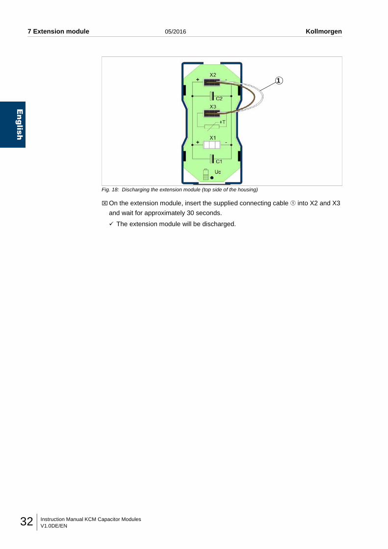
Instruction Manual KCM Capacitor ModulesV1.0DE/EN32
English
7 Extension module 05/2016 Kollmorgen
Fig. 18: Discharging the extension module (top side of the housing)
⌧On the extension module, insert the supplied connecting cable q into X2 and X3
and wait for approximately 30 seconds.
The extension module will be discharged.
1
Instruction Manual KCM Capacitor ModulesV1.0DE/EN 33
Kollmorgen 05/2016 7 Extension module
English
Fig. 19: Discharging the KCM Capacitor Module (top side of the housing)
⌧On the extension module, disconnect the connecting cable from X2, connect it to
X1 of the KCM Condenser Module and wait for approx. 30 seconds.
The KCM Capacitor Module will be discharged.
Fig. 20: Connect the KCM Capacitor Module and the extension module (top side of the housing)
⌧On the extension module, detach the connecting cable from X3 and insert it into
X1 on the extension module.
The KCM Capacitor Module and the extension module are connected.
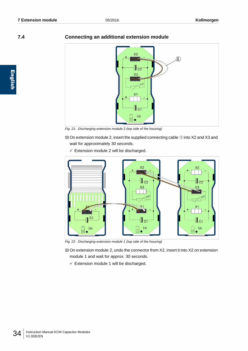
Instruction Manual KCM Capacitor ModulesV1.0DE/EN34
English
7 Extension module 05/2016 Kollmorgen
7.4 Connecting an additional extension module
Fig. 21: Discharging extension module 2 (top side of the housing)
⌧On extension module 2, insert the supplied connecting cable q into X2 and X3 and
wait for approximately 30 seconds.
Extension module 2 will be discharged.
Fig. 22: Discharging extension module 1 (top side of the housing)
⌧On extension module 2, undo the connector from X2, insert it into X2 on extension
module 1 and wait for approx. 30 seconds.
Extension module 1 will be discharged.
1
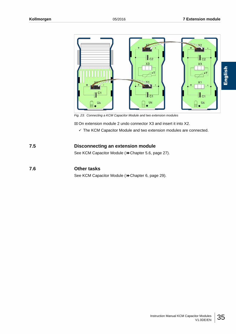
Instruction Manual KCM Capacitor ModulesV1.0DE/EN 35
Kollmorgen 05/2016 7 Extension module
English
Fig. 23: Connecting a KCM Capacitor Module and two extension modules
⌧On extension module 2 undo connector X3 and insert it into X2.
The KCM Capacitor Module and two extension modules are connected.
7.5 Disconnecting an extension moduleSee KCM Capacitor Module ( Chapter 5.6, page 27).
7.6 Other tasksSee KCM Capacitor Module ( Chapter 6, page 29).
Instruction Manual KCM Capacitor ModulesV1.0DE/EN36
Notes… 05/2016 Kollmorgen
English
Instruction Manual KCM Capacitor ModulesV1.0DE/EN 37
Kollmorgen 05/2016 Notes…
English
Service
Wir bieten Ihnen einen kompetenten und schnellen
Service. Wählen Sie das zuständige regionale
Vertriebsbüro in Deutschland oder kontaktieren Sie
den Kundenservice.
Service
We are committed to quality customer service. In
order to serve in the most effective way, please
contact your local sales representative for
assistance. If you are unaware of your local sales
representative, please contact us.
Servizio
Ci impegniamo a fornire un servizio di qualità al
cliente. Per servire nel senso più efficace, prego
mettasi in contatto con il vostro rappresentante locale
per assistenza. Contattateci per maggiori
informazioni.
Servicio
Queremos ofrecer al cliente un servicio de calidad.
Para ello les agradecemos que contacten con su
representante local de ventas. En el caso de que no
lo conozcan, no duden en ponerse en contacto con
nosotros en las siguientes direcciones.
Europe
KOLLMORGEN Customer Support Europe
Internet www.kollmorgen.com
E-Mail [email protected]
Tel.: +49 (0)2102 - 9394 - 0
Fax: +49 (0)2102 - 9394 - 3155
KOLLMORGEN European
UK Website Product WIKI
North America
KOLLMORGEN Customer Support North America
Internet www.kollmorgen.com
E-Mail [email protected]
Tel.: +1 - 540 - 633 - 3545
Fax: +1 - 540 - 639 - 4162
KOLLMORGEN KOLLMORGEN
US Website Developer Network
Asia
KOLLMORGEN
Internet www.kollmorgen.com
E-Mail [email protected]
Tel: +86 - 400 661 2802
Fax: +86 - 21 6071 0665
KOLLMORGEN
CN Website