Kawasaki Robot Arc welding robots - … · Kawasaki Robot Arc welding robots ... path, users can...
6
Cat. No. 3L1775 Mar. ’18 M Printed in Japan Kawasaki Robot ] Materials and specifications are subject to change without notice. CAUTIONS TO BE TAKEN TO ENSURE SAFETY lFor those persons involved with the operation / service of your system, including Kawasaki Robot, they must strictly observe all safety regulations at all times. They should carefully read the Manuals and other related safety documents. lProducts described in this catalogue are general industrial robots. Therefore, if a customer wishes to use the Robot for special purposes, which might endanger operators or if the Robot has any problems, please contact us. We will be pleased to help you. lBe careful as Photographs illustrated in this catalogue are frequently taken after removing safety fences and other safety devices stipulated in the safety regulations from the Robot operation system. ROBOT DIVISION Tokyo Head Office/Robot Division 1-14-5, Kaigan, Minato-ku, Tokyo 105-8315, Japan Phone: +81-3-3435-2501 Fax: +81-3-3437-9880 Akashi Works/Robot Division 1-1, Kawasaki-cho, Akashi, Hyogo 673-8666, Japan Phone: +81-78-921-2946 Fax: +81-78-923-6548 Global Network Kawasaki Robotics (USA), Inc. 28140 Lakeview Drive, Wixom, MI 48393, U.S.A. Phone: +1-248-446-4100 Fax: +1-248-446-4200 Kawasaki Robotics (UK) Ltd. Unit 4 Easter Court, Europa Boulevard, Westbrook Warrington Cheshire, WA5 7ZB, United Kingdom Phone: +44-1925-71-3000 Fax: +44-1925-71-3001 Kawasaki Robotics GmbH Im Taubental 32, 41468 Neuss, Germany Phone: +49-2131-34260 Fax: +49-2131-3426-22 Kawasaki Robotics Korea, Ltd. 43, Namdong-daero 215beon-gil, Namdong-gu, Incheon, 21633, Korea Phone: +82-32-821-6941 Fax: +82-32-821-6947 Kawasaki Robotics (Tianjin) Co., Ltd. 1·2/F, Building 6, No.19 Xinhuan Road, TEDA, China Phone: +86-22-5983-1888 Fax: +86-22-5983-1889 Kawasaki Motors Enterprise (Thailand) Co., Ltd. (Rayong Robot Center) 119/10 Moo 4 T.Pluak Daeng, A.Pluak Daeng, Rayong 21140 Thailand Phone: +66-38-955-040-58 Fax: +66-38-955-145 https://robotics.kawasaki.com/ ISO certified in Akashi Works. Kawasaki Robot Arc welding robots Arc welding robots
Transcript of Kawasaki Robot Arc welding robots - … · Kawasaki Robot Arc welding robots ... path, users can...

Cat. No. 3L1775 Mar. ’18 M
Printed in Japan
Kawasaki Robot
] Materials and specifications are subject to change without notice.
CAUTIONS TO BE TAKEN TO ENSURE SAFETY
lFor those persons involved with the operation / service of your system, including Kawasaki Robot, they must strictly observe all safety regulations at all times. They should carefully read the Manuals and other related safety documents.
lProducts described in this catalogue are general industrial robots. Therefore, if a customer wishes to use the Robot for special purposes, which might endanger operators or if the Robot has any problems, please contact us. We will be pleased to help you.
lBe careful as Photographs illustrated in this catalogue are frequently taken after removing safety fences and other safety devices stipulated in the safety regulations from the Robot operation system.
ROBOT DIVISION
Tokyo Head Office/Robot Division1-14-5, Kaigan, Minato-ku, Tokyo 105-8315, JapanPhone: +81-3-3435-2501 Fax: +81-3-3437-9880
Akashi Works/Robot Division1-1, Kawasaki-cho, Akashi, Hyogo 673-8666, JapanPhone: +81-78-921-2946 Fax: +81-78-923-6548
Global Network
Kawasaki Robotics (USA), Inc.28140 Lakeview Drive, Wixom, MI 48393, U.S.A.Phone: +1-248-446-4100 Fax: +1-248-446-4200
Kawasaki Robotics (UK) Ltd.Unit 4 Easter Court, Europa Boulevard, Westbrook Warrington Cheshire, WA5 7ZB, United KingdomPhone: +44-1925-71-3000 Fax: +44-1925-71-3001
Kawasaki Robotics GmbHIm Taubental 32, 41468 Neuss, GermanyPhone: +49-2131-34260 Fax: +49-2131-3426-22
Kawasaki Robotics Korea, Ltd.43, Namdong-daero 215beon-gil, Namdong-gu, Incheon, 21633, KoreaPhone: +82-32-821-6941 Fax: +82-32-821-6947
Kawasaki Robotics (Tianjin) Co., Ltd.1·2/F, Building 6, No.19 Xinhuan Road, TEDA, China Phone: +86-22-5983-1888 Fax: +86-22-5983-1889
Kawasaki Motors Enterprise (Thailand) Co., Ltd.(Rayong Robot Center)119/10 Moo 4 T.Pluak Daeng, A.Pluak Daeng, Rayong 21140 Thailand Phone: +66-38-955-040-58 Fax: +66-38-955-145
https://robotics.kawasaki.com/ ISO certified in Akashi Works.
Kawasaki Robot
Arc welding robots
Arc welding robots
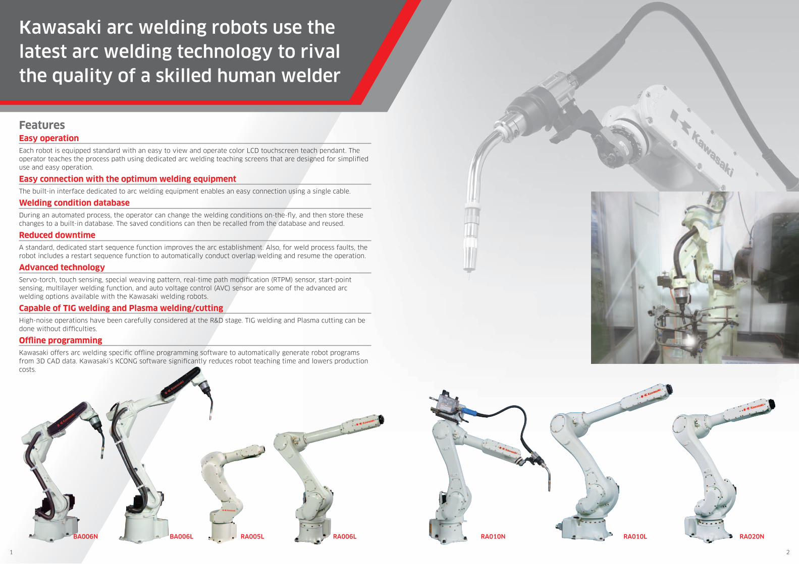
Kawasaki arc welding robots use the latest arc welding technology to rival the quality of a skilled human welder
FeaturesEasy operationEach robot is equipped standard with an easy to view and operate color LCD touchscreen teach pendant. The operator teaches the process path using dedicated arc welding teaching screens that are designed for simplified use and easy operation.
Easy connection with the optimum welding equipment The built-in interface dedicated to arc welding equipment enables an easy connection using a single cable.
Welding condition databaseDuring an automated process, the operator can change the welding conditions on-the-fly, and then store these changes to a built-in database. The saved conditions can then be recalled from the database and reused.
Reduced downtimeA standard, dedicated start sequence function improves the arc establishment. Also, for weld process faults, the robot includes a restart sequence function to automatically conduct overlap welding and resume the operation.
Advanced technologyServo-torch, touch sensing, special weaving pattern, real-time path modification (RTPM) sensor, start-point sensing, multilayer welding function, and auto voltage control (AVC) sensor are some of the advanced arc welding options available with the Kawasaki welding robots.
Capable of TIG welding and Plasma welding/cutting High-noise operations have been carefully considered at the R&D stage. TIG welding and Plasma cutting can be done without difficulties.
Offline programmingKawasaki offers arc welding specific offline programming software to automatically generate robot programs from 3D CAD data. Kawasaki’s KCONG software significantly reduces robot teaching time and lowers production costs.
RA020NRA010LRA010NRA006LRA005LBA006N BA006L
1 2

Standard specifications
BA006N BA006L RA005L RA006L RA010N RA010L RA020N
Type Articulated robot
Degree of freedom (axes) 6
Max. payload (kg) 6 6 5 6 10 10 20
Max. reach (mm) 1,445 2,036 903 1,650 1,450 1,925 1,725
Positional repeatability (mm) ]1 ±0.06 ±0.08 ±0.03 ±0.03 ±0.03 ±0.05 ±0.04
Motion range(°)
Arm rotation (JT1) ±165 ±165 ±180 ±180 ±180 ±180 ±180
Arm out-in (JT2) +150 - –90 +150 - –90 +135 - –80 +145 - –105 +145 - –105 +155 - –105 +155 - –105
Arm up-down (JT3) +90- –175 +90- –175 +118 - –172 +150 - –163 +150 - –163 +150 - –163 +150 - –163
Wrist swivel (JT4) ±180 ±180 ±360 ±270 ±270 ±270 ±270
Wrist bend (JT5) ±135 ±135 ±145 ±145 ±145 ±145 ±145
Wrist twist (JT6) ±360 ±360 ±360 ±360 ±360 ±360 ±360
Max. speed(°/s)
Arm rotation (JT1) 240 210 300 250 250 190 190
Arm out-in (JT2) 240 210 300 250 250 205 205
Arm up-down (JT3) 220 220 300 215 215 210 210
Wrist swivel (JT4) 430 430 460 365 365 400 400
Wrist bend (JT5) 430 430 460 380 380 360 360
Wrist twist (JT6) 650 650 740 700 700 610 610
Moment(N·m)
Wrist swivel (JT4) 12 12 12.3 13 22 22 45
Wrist bend (JT5) 12 12 12.3 13 22 22 45
Wrist twist (JT6) 3.75 3.75 7 7.5 10 10 29
Moment of Inertia(kg·m2)
Wrist swivel (JT4) 0.4 0.4 0.4 0.45 0.7 0.7 0.9
Wrist bend (JT5) 0.4 0.4 0.4 0.45 0.7 0.7 0.9
Wrist twist (JT6) 0.07 0.07 0.12 0.14 0.2 0.2 0.3
Mass (kg) 150 160 37 150 150 230 230
Body color Munsell 10GY9/1 equivalent
Installation Floor, Ceiling
Environmentalcondition
Ambient temperature (°C) 0 - 45
Relative humidity (%) 35 - 85 (No dew, nor frost allowed)
Power requirements (kVA) ]2 2.0 2.0 1.5 2.0 2.0 3.0 3.0
Controller
America
E01
E77
E01Europe E71
Japan & Asia E74
]1: conforms to ISO9283 ]2: depends on the payload and motion patterns
Optional equipment
• Shock sensor
• Torch bracket (350 A/500 A)
• Installation base (600 mm / 300 mm)
• Base plate (750 mm × 750 mm × 25 mm)
• Linear slide
• Positioner
• Servo torch
• RTPM (arc sensor)
• AVC (arc-sensor dedicated to TIG welding)
• 3D laser sensor
• Wall mounting
KCONG Kawasaki Common Offline NC data Generator
Servo Torch
KCONG, our offline programming software, automatically generates a robot’s welding path based off of workpiece geometry.
Kawasaki’s servo torch option delivers high quality welding.
FeaturesNo need for time-consuming robot teaching
KCONG generates robot welding paths quickly and easily from 3D CAD data such as DXF, IGES, STEP or VRML.
Offline process verification
Once KCONG automatically generates the robot welding path, users can then view the simulation of the arc welding process, check for collisions, weld access, and system layout issues, and make fine adjustments to the generated welding path.
Direct program download
After verifying the weld process and making any necessary adjustments, the operation program is generated by KCONG. The completed weld operation program can then be downloaded directly to the robot controller.
FeaturesCan be used with small-gauge iron or aluminum wire
Feeds small-gauge iron wire (ø 0.6 mm) or aluminum wire steadily with no buckling.
Excellent arc stability
The constant-speed wire feed control improves wire feeding performance, resulting in excellent arc stability.
Improved arc ignition performance
The servo torch can control complex wire feeding at the start and end of welding operations, thereby improving arc ignition.
3 4
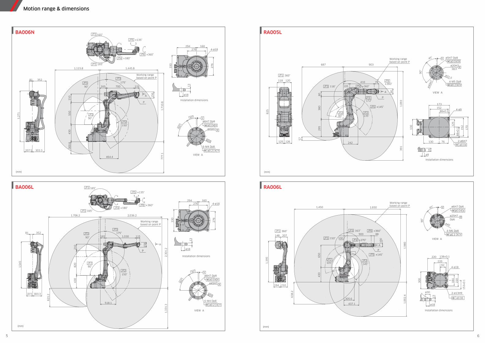
Motion range & dimensions
(mm)
165°
1,445.81,115.8
JT4 ±180°
JT5 ±135°
JT6 ±360°
165°
81 352
JT2
JT3
JT1
JT1
ø18
13
X
X
ø0.04
Y
ø0.2 X Y
ø6H7 Dp8
ø45H760°
30°
ø56
6-M4 Dp8ø66
294
33
0
4-ø18276
27
6
160
A
77
7.1
1,7
10
.8
30
0.8
1,2
71
207.5 303.3
464.4
165 700
43
05
50
21
0
115
15
6
JT2
JT3
PInstallation dimensions
VIEW A
Working rangebased on point P
90°
175°
90°
150°
(mm)
165°
JT4 ±180°
JT5 ±135°
JT6 ±360°
165°
JT2
JT3
JT1
JT1
ø18
13
X
X
ø0.04
Y
ø0.2 X Y
ø6H7 Dp8
ø45H760°
30°
ø56
6-M4 Dp8ø66
294
33
0
4-ø18276
27
6
160
JT2
JT3
1,030
62
1.2
518.1
82
0
115
43
0
15
6
21
0
2,036.2
165
1,3
31
.32
,30
1.2
1,706.2
303.3
81
1,5
41
352
207.5
P
A
175°
90°
150°
90°
Installation dimensions
VIEW A
Working rangebased on point P
BA006N
BA006L
(mm)
4-ø18
2-ø13H9
ø6H7 Dp6
ø0.04
ø0.06
ø0.3
ø40
ø25H7
Dp6
ø18
ø30
A
100
88900
210194
148 207
65
04
30
1,0
02
.41
,98
0
63
8.2
1,450 1,650
305.6
437.1
10
0
1,1
95
XY
YX
X
90
°
45°
4-M6 Dp8
92
220
138±0.1220
18
4
22
0
15
3±
0.130
0
13
JT2 105°
JT2145°
JT3 150°
JT3 163°JT1 360°
JT4 ±270°
JT5 ±145°
JT6 ±360°
P
Installation dimensions
VIEW A
Working rangebased on point P
RA006L
(mm)
JT6±360°
JT4 ±360°
JT5 ±145°
JT280°
JT2135°
JT3 118°
A
JT3172°
687 903
1,0
93
39
1
242
29
53
80
80
105
410 78
82
5
57
120118
126125
90
X
YX
X Y4-M5 Dp8
45°
Dp3
90
°
15
88±0.1
17
0
88
±0
.1
173152
15
212
5
76
13
0
130
JT1 360°
4-ø9
2-ø6H7
ø9
ø40H
7
ø5H7 Dp8
ø0.04
ø0.04
ø0.2
ø31.5
ø20H7
P
Installation dimensions
VIEW A
Working rangebased on point P
RA005L
5 6
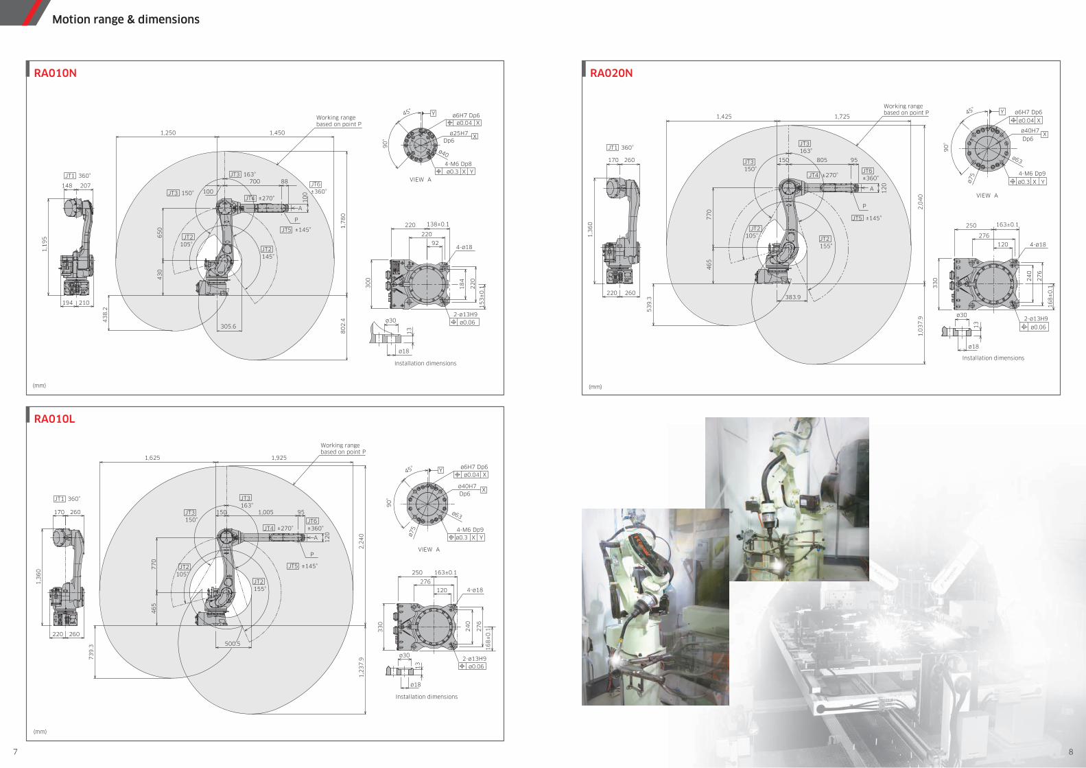
Motion range & dimensions
(mm)
13
ø30
ø18
2-ø13H9ø0.06
JT1 360°
4-ø18
45°
90
°
ø75 4-M6 Dp9
ø63
X
X
Yø0.3
ø0.04
Xø40H7Dp6
ø6H7 Dp6
JT2155°
JT2105°
JT3150°
JT3 163°
276
163±0.1250
120
24
0
27
6
16
8±
0.13
30
Y
JT4 ±270°
JT5 ±145°
JT6±360°
1,9251,625
A
2,2
40
1,005
77
04
65
500.5
1,2
37
.973
9.3
260220
260
1,3
60
170 95150
12
0
P
Installation dimensions
VIEW A
Working rangebased on point P
RA010L
(mm)
JT1 360°
JT5 ±145°
JT4 ±270°JT6±360°
250
33
0
13
276
120 4-ø18
ø30
24
0
27
6
ø18
163±0.1
16
8±
0.1
2-ø13H9
ø0.06
45°
90
°
ø75
Y
4-M6 Dp9
ø63
X
X
X
Yø0.3
ø0.04
ø40H7
Dp6
ø6H7 Dp61,425 1,725
2,0
40
1,0
37
.9
A 12
0
77
04
65
1,3
60
53
9.3
JT2155°
JT2105°
JT3150°
JT3163°
150260170
260220
95805
383.9
P
Installation dimensions
VIEW A
Working rangebased on point P
RA020N
(mm)
4-ø18
A
100
700 88
210194
148 207
65
04
30
80
2.4
1,7
80
43
8.2
1,250 1,450
305.6
10
0
1,1
95
Y
X
90
°
45°
Dp6
92
220
138±0.1220
18
4
22
0
15
3±
0.13
00
13
JT2 105°
JT2 145°
JT3 150°
JT3 163°JT1 360°
JT4 ±270°
JT5 ±145°
JT6 ±360°
ø30
ø18
ø40
4-M6 Dp8X Yø0.3
ø25H7
Xø0.04ø6H7 Dp6
2-ø13H9ø0.06
P
Installation dimensions
VIEW A
Working rangebased on point P
RA010N
7 8
USB
RS-232C
DIO board
External-axis motor
Standard
Option
Optional board
Optional device
Ethernet
DeviceNet board, master/slave
CC-Link board, master/slave
PROFIBUS board, master/slave
PROFINET board, master/slave
Ethernet/IP board, master/slave
CAN open board, slave
EtherCAT board, master/slave
Cubic-S✽1 (area monitor/speed monitor)
Conveyor I/F board
Option switch✽2
Rapid-feed checkmode switch✽1
Transformer unit✽1
Teach pendant
Terminal software
Terminal software
Vision controller
USB Memory
Brake release switch
DIO board: 32 points eachmax. 3 boards (96 points)
✽1 E01 only✽2 E7X only
POWER
REPEATTEACH
420 500
25
02
60
18
18
17
09
POWER100% CONTROL
REPEATTEACHOFF ON R
PS OT
EM CG
E YNE
580 550
580 550
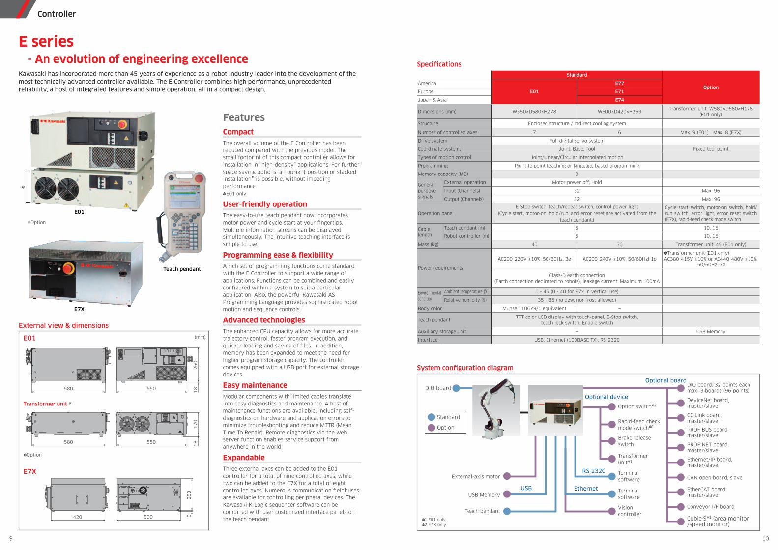
Controller
Teach pendant
System configuration diagram
Specifications
External view & dimensions
E01 (mm)
Transformer unit ]
E7X
E series - An evolution of engineering excellenceKawasaki has incorporated more than 45 years of experience as a robot industry leader into the development of the most technically advanced controller available. The E Controller combines high performance, unprecedented reliability, a host of integrated features and simple operation, all in a compact design.
FeaturesCompactThe overall volume of the E Controller has been reduced compared with the previous model. The small footprint of this compact controller allows for installation in “high-density” applications. For further space saving options, an upright-position or stacked installation] is possible, without impeding performance.]E01 only
User-friendly operationThe easy-to-use teach pendant now incorporates motor power and cycle start at your fingertips. Multiple information screens can be displayed simultaneously. The intuitive teaching interface is simple to use.
Programming ease & flexibilityA rich set of programming functions come standard with the E Controller to support a wide range of applications. Functions can be combined and easily configured within a system to suit a particular application. Also, the powerful Kawasaki AS Programming Language provides sophisticated robot motion and sequence controls.
Advanced technologiesThe enhanced CPU capacity allows for more accurate trajectory control, faster program execution, and quicker loading and saving of files. In addition, memory has been expanded to meet the need for higher program storage capacity. The controller comes equipped with a USB port for external storage devices.
Easy maintenanceModular components with limited cables translate into easy diagnostics and maintenance. A host of maintenance functions are available, including self-diagnostics on hardware and application errors to minimize troubleshooting and reduce MTTR (Mean Time To Repair). Remote diagnostics via the web server function enables service support from anywhere in the world.
ExpandableThree external axes can be added to the E01 controller for a total of nine controlled axes, while two can be added to the E7X for a total of eight controlled axes. Numerous communication fieldbuses are available for controlling peripheral devices. The Kawasaki K-Logic sequencer software can be combined with user customized interface panels on the teach pendant.
E01
E7X
Standard
OptionAmerica
E01
E77
Europe E71
Japan & Asia E74
Dimensions (mm) W550×D580×H278 W500×D420×H259Transformer unit: W580×D580×H178
(E01 only)
Structure Enclosed structure / Indirect cooling system
Number of controlled axes 7 6 Max. 9 (E01) Max. 8 (E7X)
Drive system Full digital servo system
Coordinate systems Joint, Base, Tool Fixed tool point
Types of motion control Joint/Linear/Circular Interpolated motion
Programming Point to point teaching or language based programming
Memory capacity (MB) 8
Generalpurposesignals
External operation Motor power off, Hold
Input (Channels) 32 Max. 96
Output (Channels) 32 Max. 96
Operation panelE-Stop switch, teach/repeat switch, control power light
(Cycle start, motor-on, hold/run, and error reset are activated from the teach pendant.)
Cycle start switch, motor-on switch, hold/run switch, error light, error reset switch (E7X), rapid-feed check mode switch
Cablelength
Teach pendant (m) 5 10, 15
Robot-controller (m) 5 10, 15
Mass (kg) 40 30 Transformer unit: 45 (E01 only)
Power requirements
AC200-220V ±10%, 50/60Hz, 3ø AC200-240V ±10%l 50/60Hzl 1ø]Transformer unit (E01 only)AC380-415V ±10% or AC440-480V ±10%
50/60Hz, 3ø
Class-D earth connection (Earth connection dedicated to robots), leakage current: Maximum 100mA
Environmentalcondition
Ambient temperature (°C) 0 - 45 (0 - 40 for E7x in vertical use)
Relative humidity (%) 35 - 85 (no dew, nor frost allowed)
Body color Munsell 10GY9/1 equivalent —
Teach pendantTFT color LCD display with touch-panel, E-Stop switch,
teach lock switch, Enable switch
Auxiliary storage unit — USB Memory
Interface USB, Ethernet (100BASE-TX), RS-232C
]Option
]
]Option
9 10