
Kaushal drive
33
DC DRIVES WITH DC-DC CONVERTER PREPARED BY:- kaushal boghani (130760109002) SUBMITED TO:-Prof. Archan Patel. Prof. Richa Mali. SHREE SWAMI ATMANAND SARASWATI INSTITUTE OF TECHNOLOGY.
-
Upload
kaushal-boghani -
Category
Engineering
-
view
239 -
download
0
Transcript of Kaushal drive

DC DRIVES WITH DC-DC CONVERTER
PREPARED BY:- kaushal boghani (130760109002)SUBMITED TO:-Prof. Archan Patel. Prof. Richa Mali.
SHREE SWAMI ATMANAND SARASWATI INSTITUTE OF
TECHNOLOGY.

CONTENTAbstractIntroductionBodyConclusionReference
ABSTRACT:-•Here we are going to study about the design of dc drive with use of dc – dc converter or dc chopper .design of choke coil 1-phase and 3-phase variable choke coil.
•We will also cover the topic like how duty cycle is affected to speed of motor and armature voltage .
•We are going to study about the different mode of operation like motoring mode regenerating mode in different quadrant with circuit diagram.
•equation of power , armature voltage , armature current and speed in terms of duty cycle .
•Waveforms of different quantities .
•We are going to see the application of different mode of operation of dc motor by use of dc drive with dc chopper .
INTRODUCTION•The dc to dc converter or chopper based dc motor drives are widely used in traction application.
•By varying duty cycle we can control the speed of dc motor and armature voltage.
•Chopper provides the regenerative braking which returns energy to source and improves efficiency.
•Chopper drives can operate in one , two, or four quadrant.
MODE OF OPERATION
1. Principle of Power Control
2. Principle of Regenerative Brake Control
3. Principle of Rheostatic Brake Control
4. Combined Regenerative and Rheostatic Brake Control
5. Two and Four Quadrant DC – DC Converter Drives
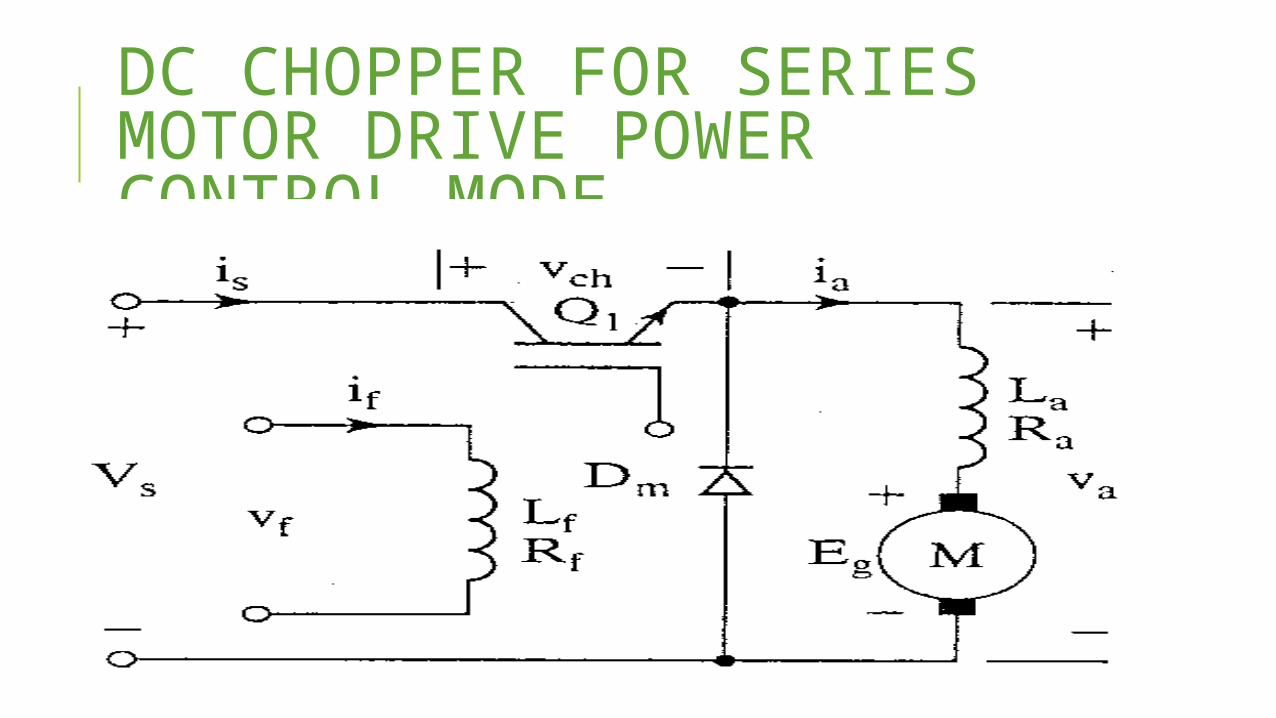
DC CHOPPER FOR SERIES MOTOR DRIVE POWER CONTROL MODE
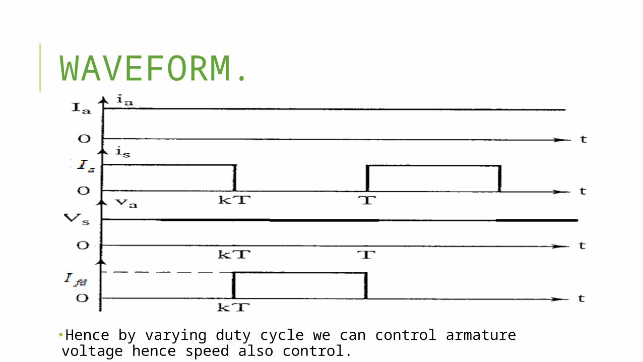
WAVEFORM.
•Hence by varying duty cycle we can control armature voltage hence speed also control.
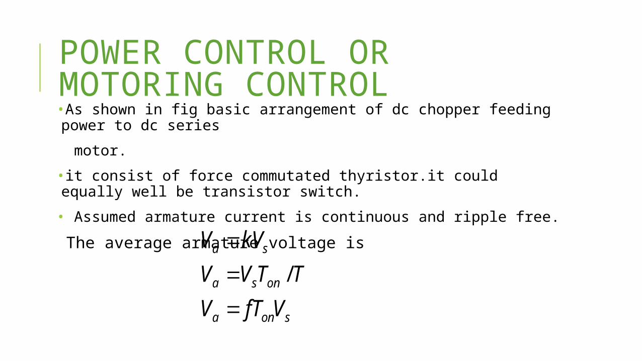
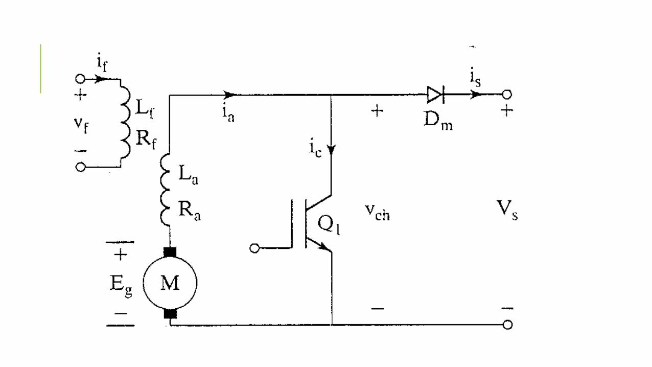
POWER CONTROL OR MOTORING CONTROL•As shown in fig basic arrangement of dc chopper feeding power to dc series
motor.
•it consist of force commutated thyristor.it could equally well be transistor switch.
• Assumed armature current is continuous and ripple free.
The average armature voltage is
sona
onsa
sa
VfTVTTVV
kVV
/
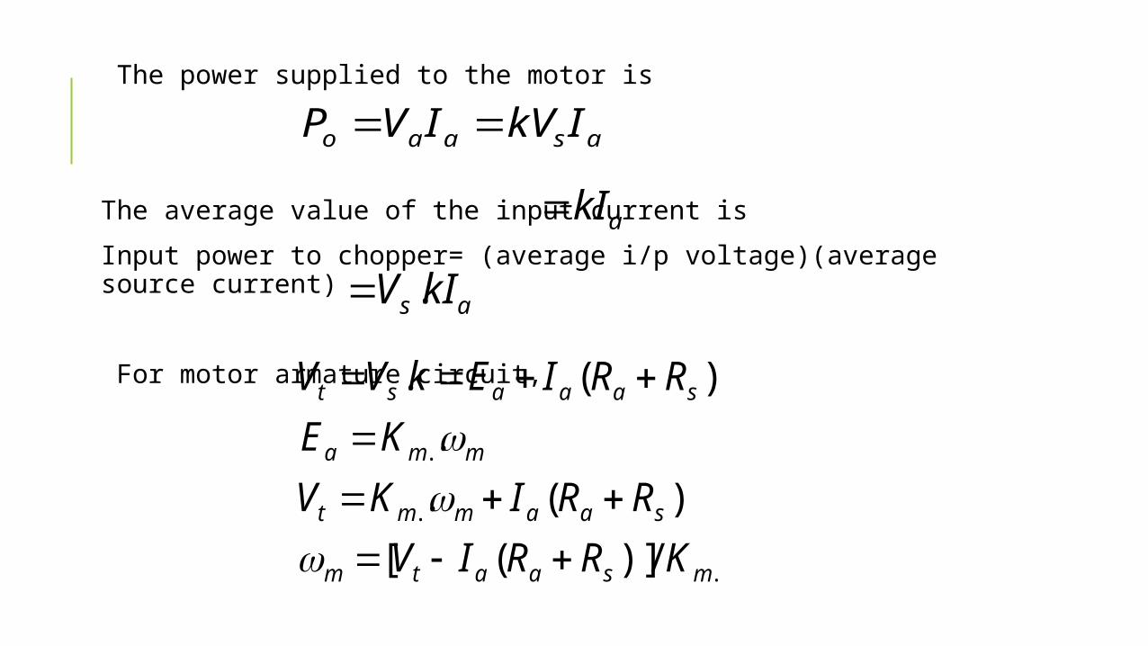
The power supplied to the motor is
The average value of the input current is
Input power to chopper= (average i/p voltage)(average source current)
For motor armature circuit,
asaao IkVIVP
as kIV .
.
.
.
/)]([)(.
.)(.
msaatm
saammt
mma
saaast
KRRIVRRIKV
KERRIEkVV
akI
REGENERATIVE BRAKING CONTROL•In regenerative braking control motor act as generator and kinetic energy of motor is connected to load is returned to source.
•During motoring mode supply voltage is larger than back emf but in case of regenerating mode back emf is greater than supply voltage
•During chopper is on and it act as short circuited and becomes zero. during
• period F.D conduct and becomes high & current flows into the supplyonT tV
offT tV
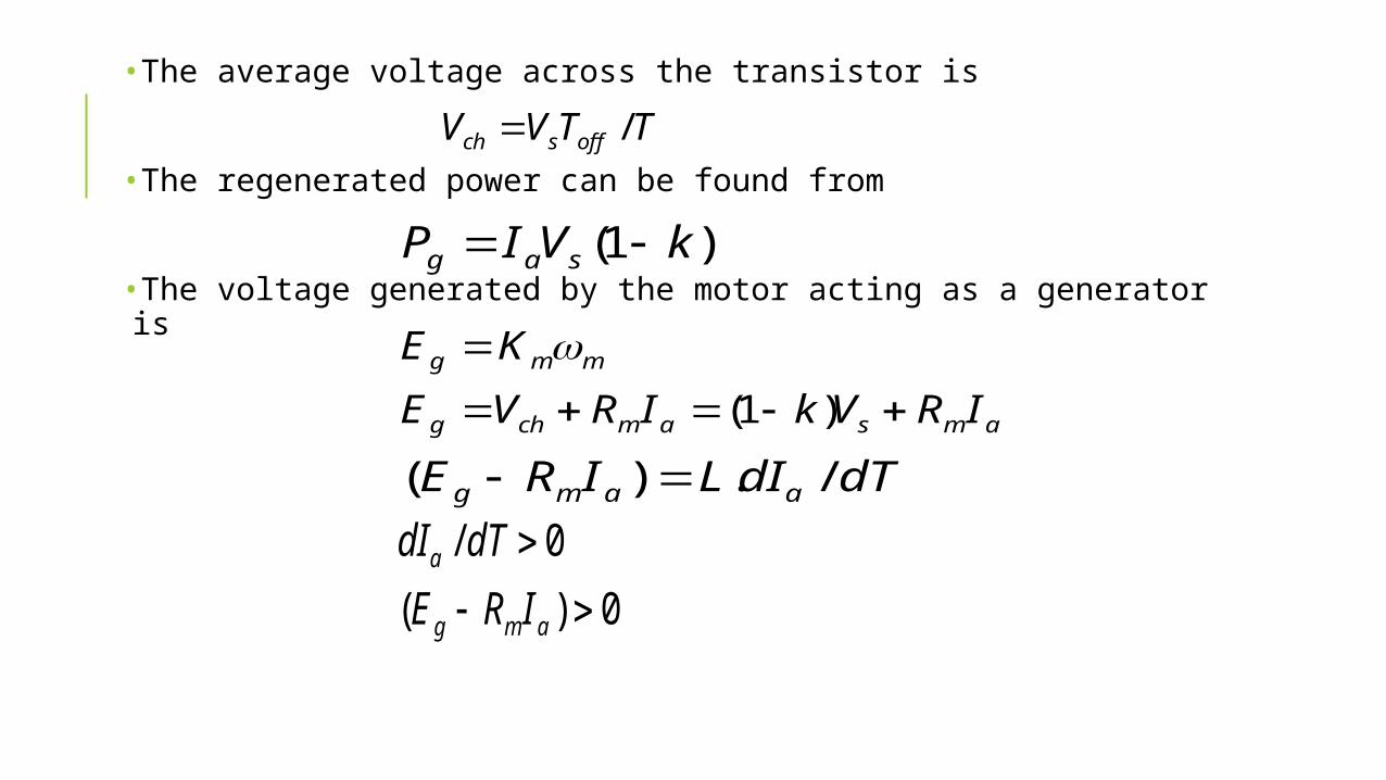
•The average voltage across the transistor is
•The regenerated power can be found from
•The voltage generated by the motor acting as a generator is
TTVV offsch /
)1( kVIP sag
amsamchg
mmg
IRVkIRVE
KE
)1(
dTdILIRE aamg /.)(
0)(0/
amg
a
IREdTdI
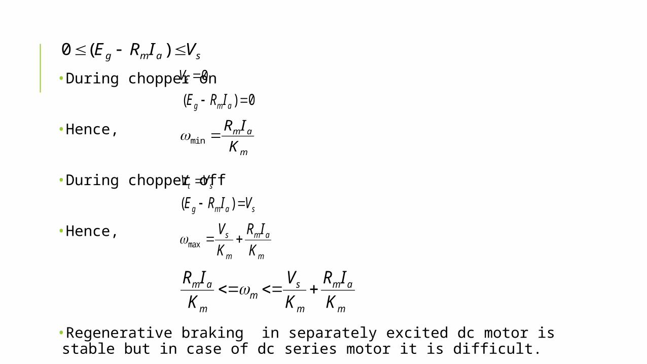
•During chopper on
•Hence,
•During chopper off
•Hence,
•Regenerative braking in separately excited dc motor is stable but in case of dc series motor it is difficult.
samg VIRE )(00tV
0)( amg IRE
m
am
KIR
min
st VV
samg VIRE )(
m
am
m
s
KIR
KV
max
m
am
m
sm
m
am
KIR
KV
KIR
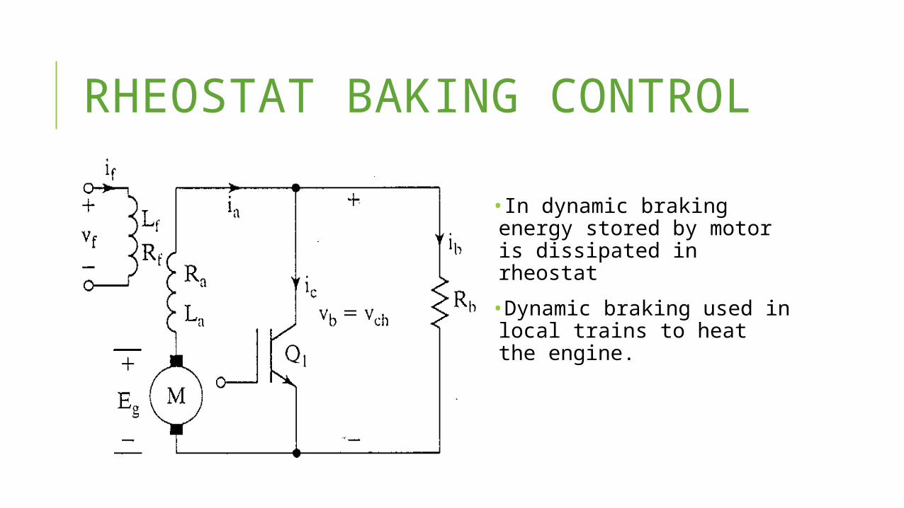
RHEOSTAT BAKING CONTROL
•In dynamic braking energy stored by motor is dissipated in rheostat
•Dynamic braking used in local trains to heat the engine.
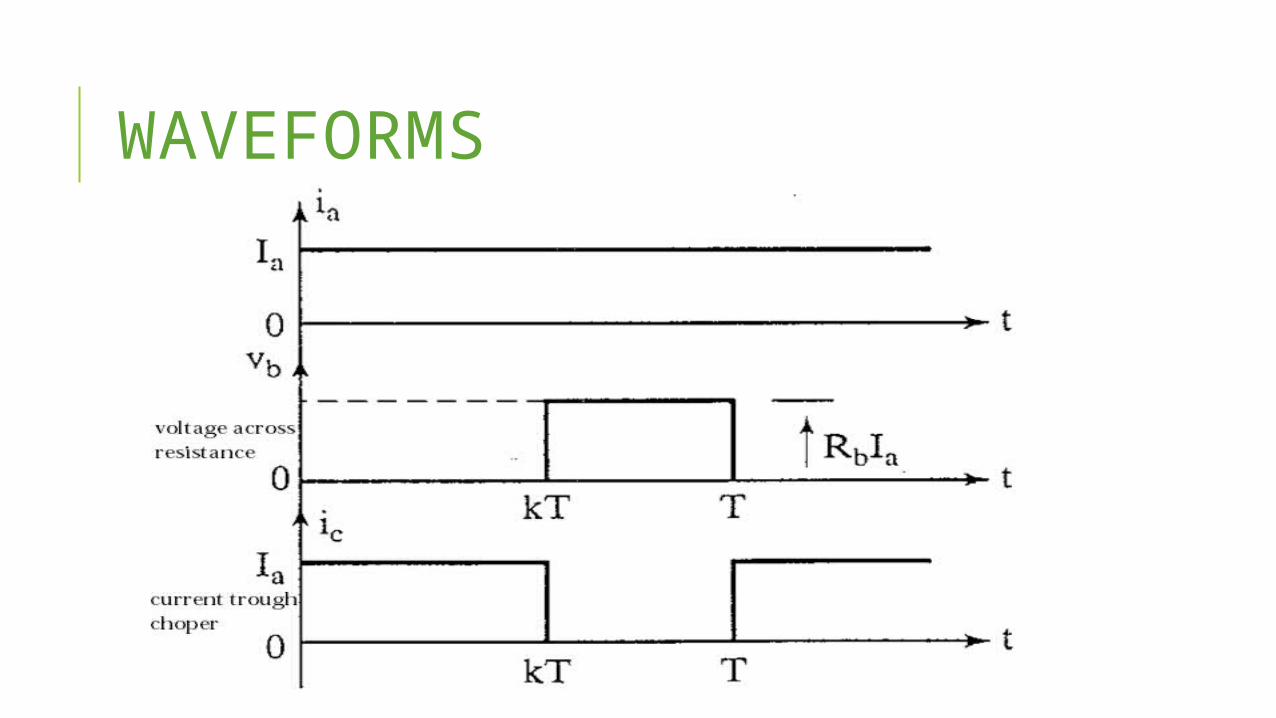
WAVEFORMS
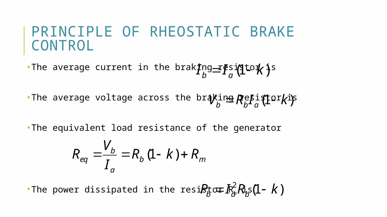
PRINCIPLE OF RHEOSTATIC BRAKE CONTROL•The average current in the braking resistor is
•The average voltage across the braking resistor is
•The equivalent load resistance of the generator
•The power dissipated in the resistor Rb is
)1( kII ab
)1( kIRV abb
mba
beq RkR
IVR )1(
)1(2 kRIP bab
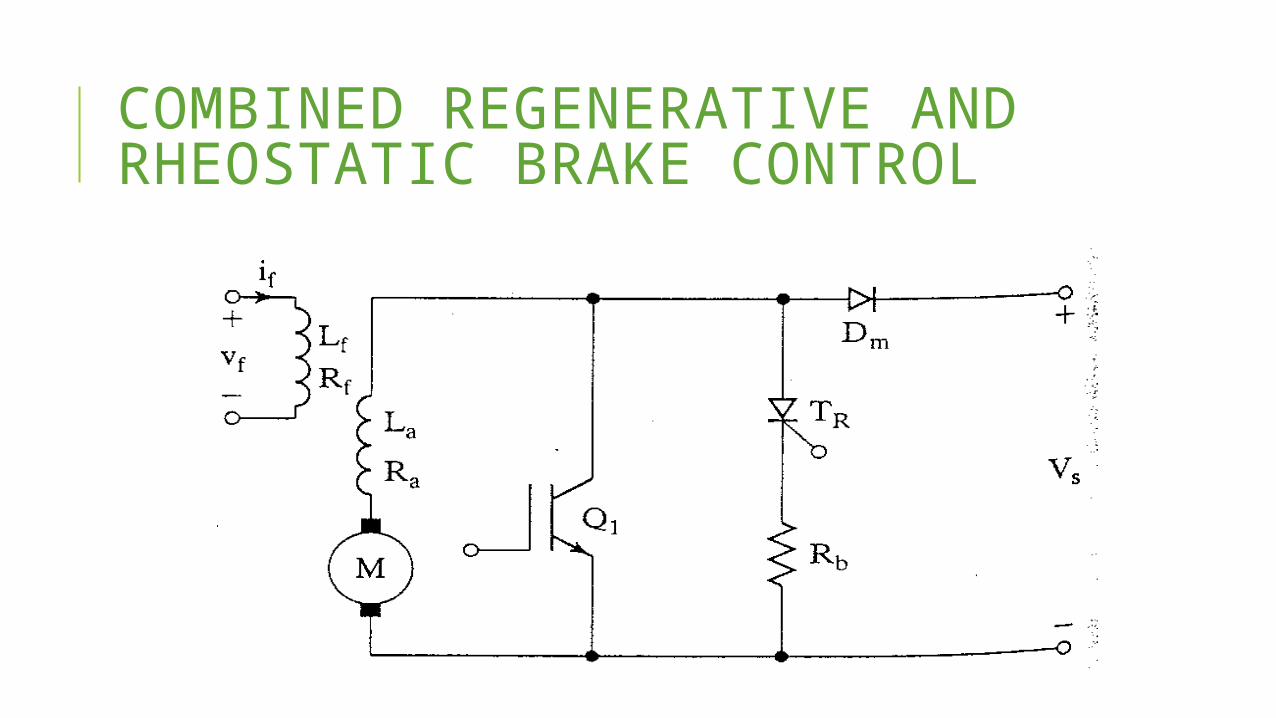
COMBINED REGENERATIVE AND RHEOSTATIC BRAKE CONTROL
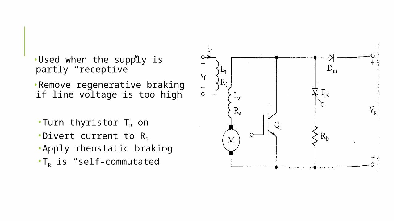
•Used when the supply is partly “receptive”
•Remove regenerative braking if line voltage is too high
•Turn thyristor TR on•Divert current to RB
•Apply rheostatic braking•TR is “self-commutated”
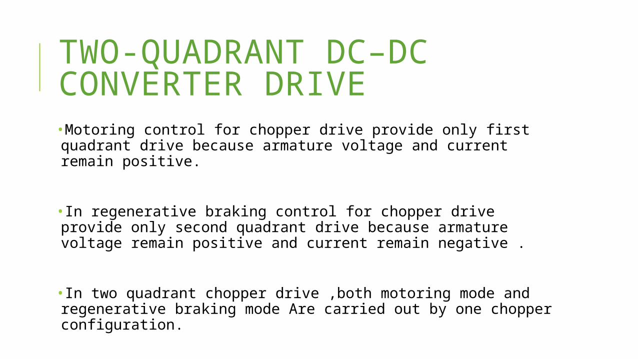
TWO-QUADRANT DC–DC CONVERTER DRIVE•Motoring control for chopper drive provide only first quadrant drive because armature voltage and current remain positive.
•In regenerative braking control for chopper drive provide only second quadrant drive because armature voltage remain positive and current remain negative .
•In two quadrant chopper drive ,both motoring mode and regenerative braking mode Are carried out by one chopper configuration.
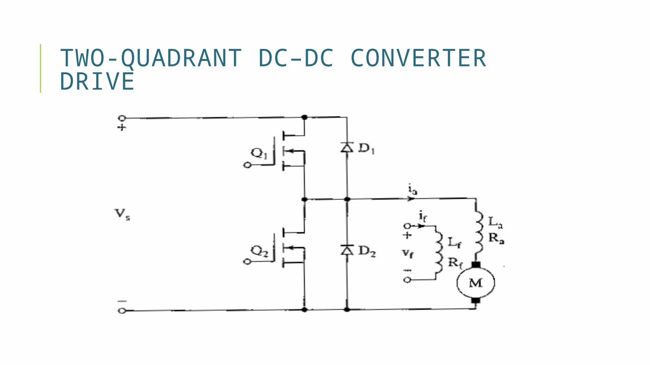
TWO-QUADRANT DC–DC CONVERTER DRIVE
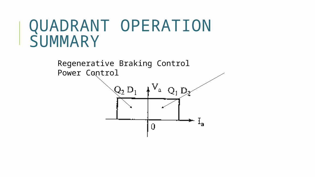
QUADRANT OPERATION SUMMARY
Regenerative Braking Control Power Control
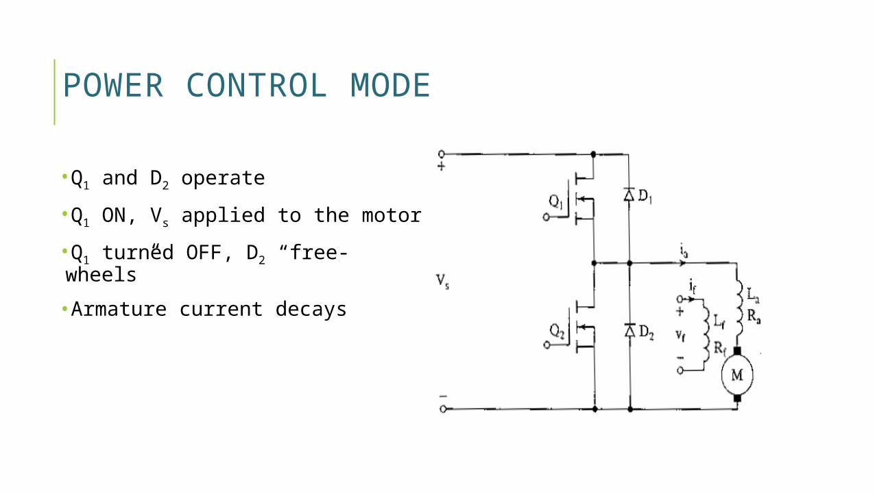
POWER CONTROL MODE
•Q1 and D2 operate
•Q1 ON, Vs applied to the motor
•Q1 turned OFF, D2 “free-wheels”
•Armature current decays
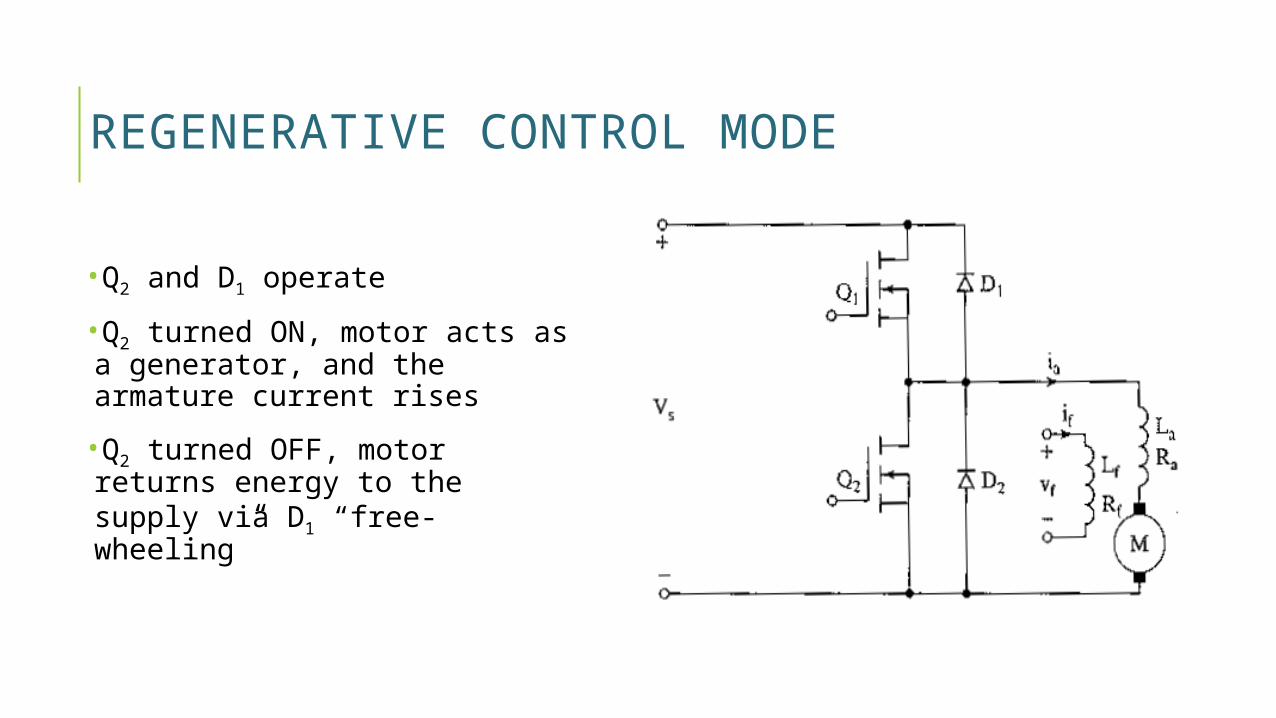
REGENERATIVE CONTROL MODE
•Q2 and D1 operate
•Q2 turned ON, motor acts as a generator, and the armature current rises
•Q2 turned OFF, motor returns energy to the supply via D1 “free-wheeling”
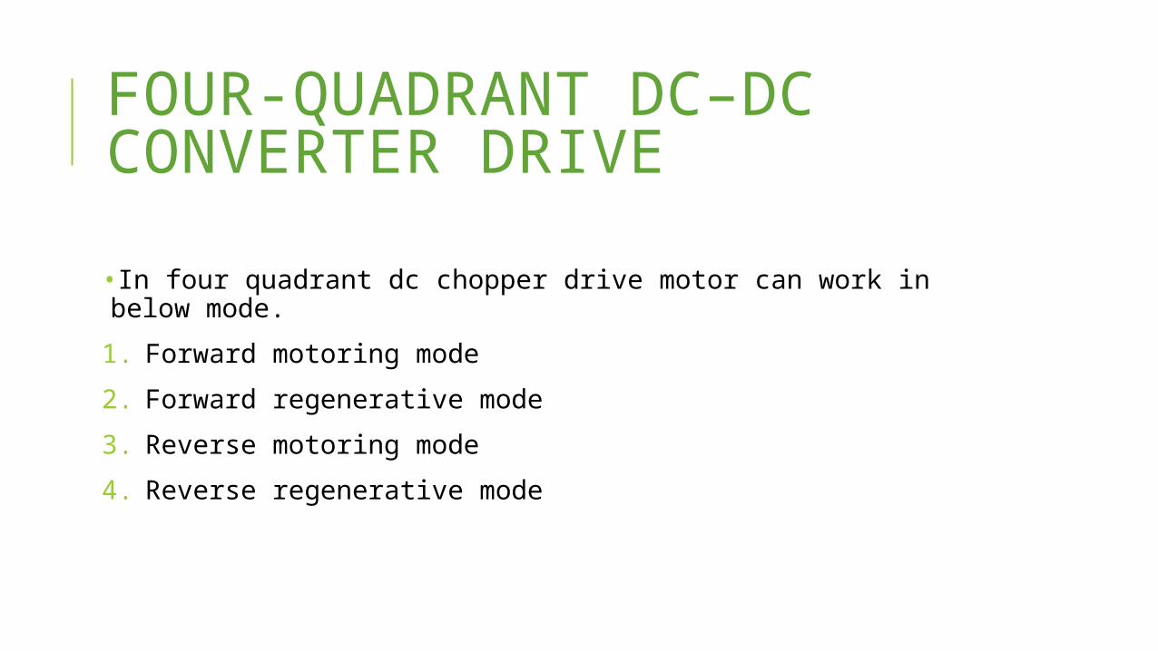
FOUR-QUADRANT DC–DC CONVERTER DRIVE•In four quadrant dc chopper drive motor can work in below mode.
1. Forward motoring mode
2. Forward regenerative mode
3. Reverse motoring mode
4. Reverse regenerative mode
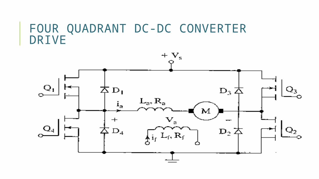
FOUR QUADRANT DC-DC CONVERTER DRIVE
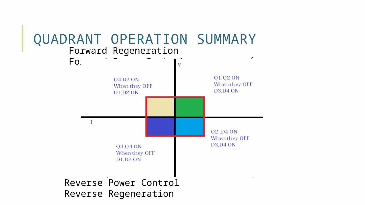
QUADRANT OPERATION SUMMARYForward Regeneration Forward Power Control
Reverse Power Control Reverse Regeneration
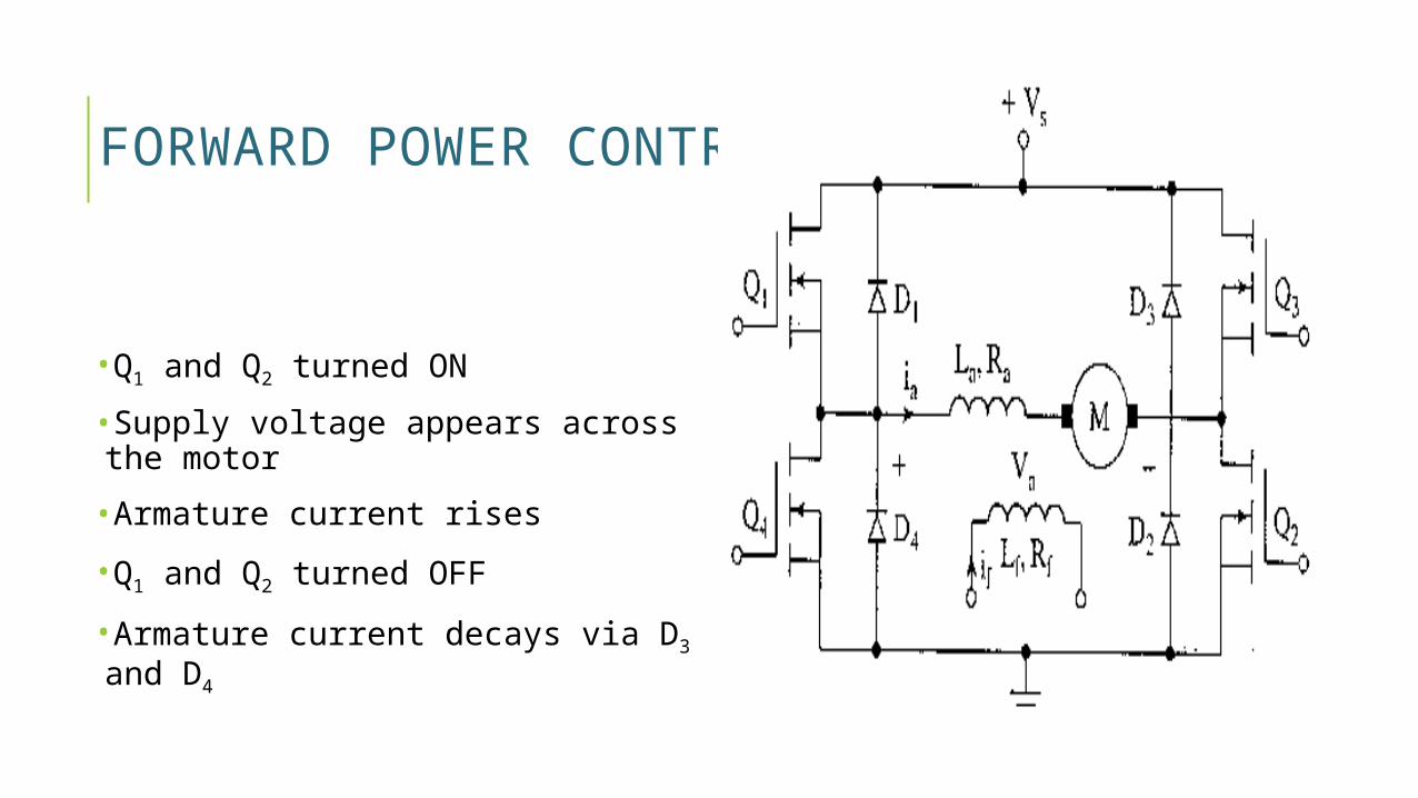
FORWARD POWER CONTROL MODE
•Q1 and Q2 turned ON
•Supply voltage appears across the motor
•Armature current rises
•Q1 and Q2 turned OFF
•Armature current decays via D3 and D4
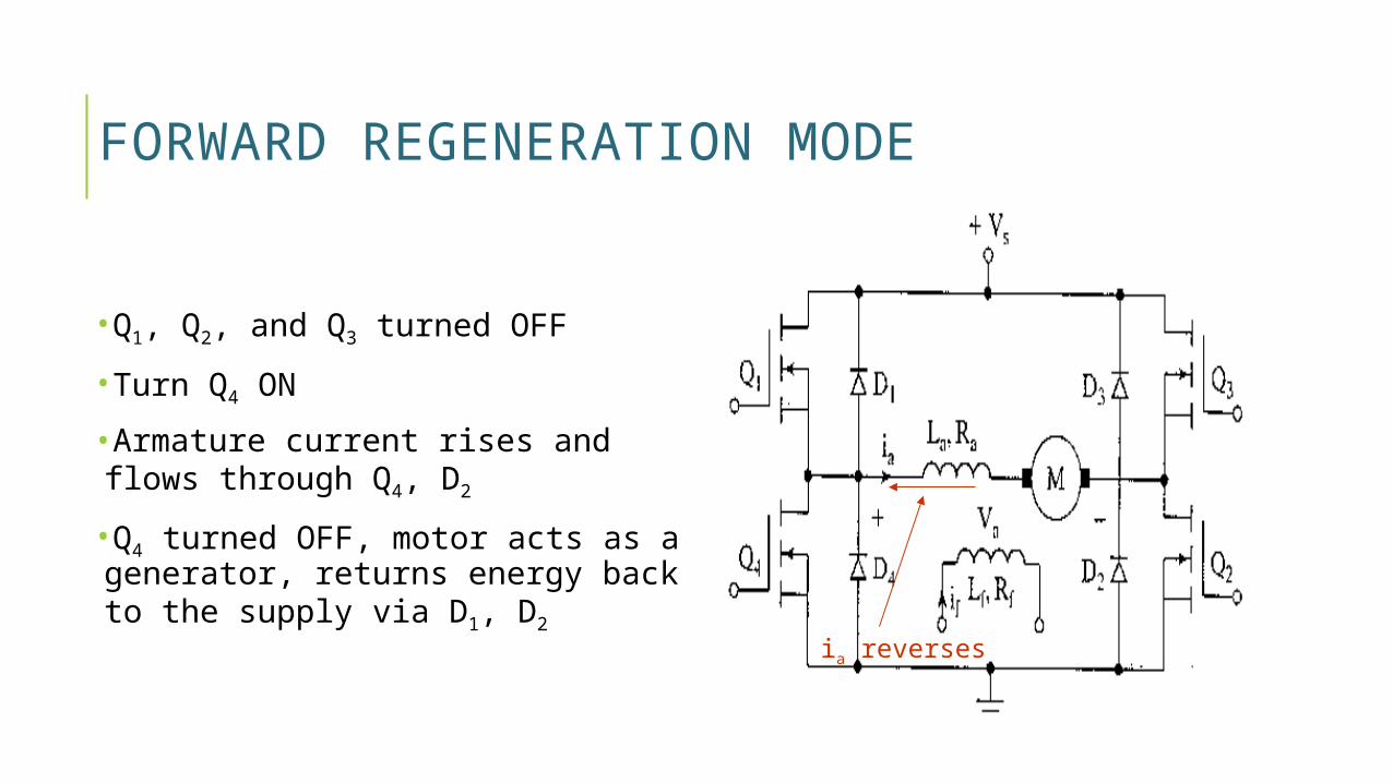
FORWARD REGENERATION MODE
•Q1, Q2, and Q3 turned OFF
•Turn Q4 ON
•Armature current rises and flows through Q4, D2
•Q4 turned OFF, motor acts as a generator, returns energy back to the supply via D1, D2
ia reverses
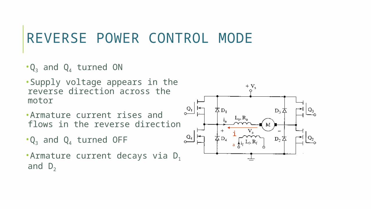
REVERSE POWER CONTROL MODE•Q3 and Q4 turned ON
•Supply voltage appears in the reverse direction across the motor
•Armature current rises and flows in the reverse direction
•Q3 and Q4 turned OFF
•Armature current decays via D1 and D2 ia
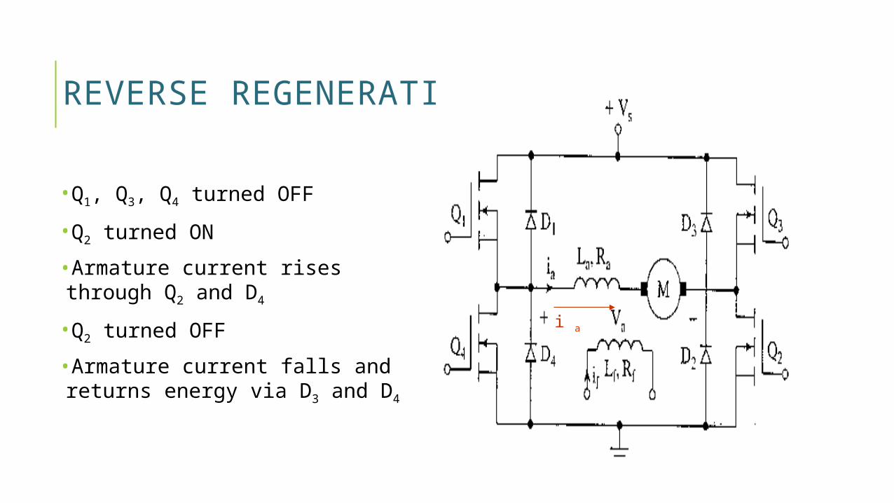
REVERSE REGENERATION MODE
•Q1, Q3, Q4 turned OFF
•Q2 turned ON
•Armature current rises through Q2 and D4
•Q2 turned OFF
•Armature current falls and returns energy via D3 and D4
i a

REFRENCESPOWER ELECTRONICS KHANNA PUBLICATION BY Dr .P.S.BIMBHRAwww.faculty.umassed.edu/xtras.3910.comwww.site.uottawa.ca/hfh.365.com

Thank you


![[IJCST-V3I4P31]:Parvesh Kaushal, Mr. Amarvir Singh](https://static.fdocuments.net/doc/165x107/563dbbae550346aa9aaf5845/ijcst-v3i4p31parvesh-kaushal-mr-amarvir-singh.jpg)
