
KAPITEL 12 - rvs.uni-bielefeld.de · KAPITEL 12 An Overview of IEC 61508 on E/E/PE Functional...
42
KAPITEL 12 An Overview of IEC 61508 on E/E/PE Functional Safety Peter B. Ladkin 2008 12.1 What IEC 61508 is about, how it is standardised, how used The International Electrotechnical Commission is the organisation which develops and sets international standards in electrotechnical engineering areas. In 1997 the IEC published the standard IEC 61508, Functional safety of electrical/electronic/pro- grammable electronic safety-related systems. The phrase „electrical/electronic/pro- grammable electronic“ is cumbersome and is often shortened to E/E/PE, which some pronounce „ee-ee-pee-ee“ and others such as myself „eepee“. The standard has been slowly making its way into the safety-critical and safety- related digital systems mainstream over the last decade. The British Health and Safety Executive (HSE) uses it as a measure of whether a safety-critical system has reduced risk „as low as reasonably practicable“, a requirement of English law, otherwise known as ALARP. The terminology ALARP refers back to a judgment by Lord Asquith of Bishopstone in the English case Edwards vs. National Coal Board in 1949 in which Lord Asquith also issued guidance as to the meaning of the phrase „reasonably practicable“. It is intended that there shall be sector-specific norms deriving from IEC 61508, which will take precedence in those sectors for which they exist. So, for example, the European Committee for Electrotechnical Standardisation (Europisches Komitee fr elektrotechnische Normung) CENELEC issues standards
Transcript of KAPITEL 12 - rvs.uni-bielefeld.de · KAPITEL 12 An Overview of IEC 61508 on E/E/PE Functional...

KAPITEL 12An Overview of IEC 61508 on E/E/PE Functional SafetyPeter B. Ladkin 2008
12.1 What IEC 61508 is about, how it is standardised, howused
The International Electrotechnical Commission is the organisation which developsand sets international standards in electrotechnical engineering areas. In 1997 theIEC published the standard IEC 61508, Functional safety of electrical/electronic/pro-grammable electronic safety-related systems. The phrase „electrical/electronic/pro-grammable electronic“ is cumbersome and is often shortened to E/E/PE, which somepronounce „ee-ee-pee-ee“ and others such as myself „eepee“.
The standard has been slowly making its way into the safety-critical and safety-related digital systems mainstream over the last decade. The British Health andSafety Executive (HSE) uses it as a measure of whether a safety-critical systemhas reduced risk „as low as reasonably practicable“, a requirement of English law,otherwise known as ALARP. The terminology ALARP refers back to a judgment byLord Asquith of Bishopstone in the English case Edwards vs. National Coal Board in1949 in which Lord Asquith also issued guidance as to the meaning of the phrase„reasonably practicable“. It is intended that there shall be sector-specific normsderiving from IEC 61508, which will take precedence in those sectors for which theyexist. So, for example, the European Committee for Electrotechnical Standardisation(Europisches Komitee fr elektrotechnische Normung) CENELEC issues standards

260 12 An Overview of IEC 61508 on E/E/PE Functional Safety
for railway automation, such as EN 50128, on software for railway control andmonitoring systems which are based on, but which supercede, the requirements ofIEC 61508.
12.2 Definitions of Basic Concepts
Definitions devised by engineers are unfortunately not generally of the same qualityas those used by mathematicians, logicians or philosophers. However, they do givesome idea of what concepts are being addressed by a standard, and IEC 61508 is noexception.
Harm is physical injury or damage to the health of people either directly, or indirectlyas a result of damage to property or to the environment
Harm is the basic notion of what you don’t want, and the basis for explaining anotion of safety as, say, absence of harmful events, although, s we shall see, thisis not how IEC 61508 does it. There is no notion of accident as a harmful eventin IEC 61508, but rather
Hazardous event : a hazardous situation which results in harm
The standard does not explain what is meant by a situation. Given we havea definition of state, it is tempting to identify a situation as a state, since thisis how the word is used in normal everyday language. However, for us anevent is a pair of states, so an event logically cannot be a state (pairs cannot beidentical with their elements according to the usual set-theoretic logic) and itwould follow that an event logically cannot be a situation, if situations were tobe states. But the definition identifies hazardous event with a certain type ofhazardous situation, so it seems as if situations are events here. The standarddefines
Hazardous situation : a circumstance in which a person is exposed to hazard(s)
We are not much nearer, though, since the term circumstance is not defined. Letus therefore not set too much store by the word „situation“ or „circumstance“,and take a hazardous event to be an event from which harm causally results.The question arises how long or convoluted the causal chain is to be betweenhazardous event and harm, and what other factors may come into play, andhow much. For example, I ride my bicycle from my driveway onto the roadway,

12.2 Definitions of Basic Concepts 261
and as I do so a car comes around the corner on my side of the road and wipesme out. Riding my bicycle onto the roadway is certainly an event, and it didcausally result in harm, by the Counterfactual Test, since if I hadn’t done it Iwouldn’t have been wiped out. But do we really want to call it a hazardousevent and make it the center of focus? Surely the event that should be at thecenter of focus as unwanted is the fact that car and bicycle met in the samephysical place at the same time and harm directly resulted from the collision:what we would usually call an accident. And then you can ask how this mighthave happened causally, and trace precursor events. But we cannot do this withthe IEC 61508 vocabulary, which allows us no accidents; only hazardous events,and provides no guidance as to how causally „near“ an event must be to harmto count as a „hazardous event“. In fact, the state of the usage is that mostengineers of my acquaintance who are conversant with the standard would usethe phrase „hazardous event“ as equivalent to „accident or a direct precursor ofan accident“. So that is probably the best way to go.
As we have seen, hazardous events are hazardous situations and these arecircumstances in which one is exposed to a hazard, which is
Hazard : a potential source of harm
We know what harm is, but not what it is to be a source of harm, let alonea potential source. As the philosopher and logician W.V.O. Quine once asked,exactly how many potential fat men are standing in that empty doorway? Thereare long-standing difficulties with the coherence of notions of potential-this-and-thats. Let us look therefore at the notion of source. I guess a source is somekind of origin. One may guess further that what is meant is a causal origin, i.e.,a cause. We can put this together with the common usage of the term „hazard“to refer to a state out of which sometimes harm occurs, but not inevitably,and guess that maybe this is what is meant by „potential“: not inevitable. Weare familiar from Chapter XXXX with a notion of hazard as some state fromwhich an accident will result if the environment is unfavorable, and our currentnotion looks to be similar. We can imagine that a hazard might be a state, oran event, which contains a significant set of causal factors of an accident, butwhich causal set is not necessarily sufficient for an accident to occur, in otherwords that other causes have to participate. The point of the term „significant“is to indicate something like „a lot“, or „almost all“; that is, that you have a lot

262 12 An Overview of IEC 61508 on E/E/PE Functional Safety
of causal factors present in the hazard and it only requires one or two more,maybe under your control but maybe not, to „tip the scales“ and result in anaccident, that is, harm.
That is the core set of concepts in IEC 61508 which talk about what we wouldcall accidents. We have not get seen a definition of safety, and that is becausethe standard defines safety not through accidents, but through risk.
Risk: [the/a] combination of the probability of occurrence of harm and the severityof that harm
We have seen something like this before. The definition does not say how theprobability and severity are „combined“ but we have already discussed variousproposals in technical detail and can imagine that something along those linesis meant here. Now, here comes a novelty of the IEC 61508 standard:
Tolerable risk : risk which is acceptable in a given context, based on the currentvalues of society
„Acceptable“ means something which is possible to accept, or which is accepted.It is not suggested who does the accepting of the risk. Lawmakers? Politicians?Individuals exposed to harm? Other „stakeholders“? Neither is it suggested how„current values of society“ might be determined, or even to what this phraserefers. 5,000+ people die in accidents involving automobiles on the road inGermany every year; 3,000+ in Britain. Is the risk of 1 in 15,000 of dying in anygiven year on the road in Germany „acceptable“, based on the „current valuesof society“? The current value of road deaths is indeed 5000+, and peopledo drive, so it seems as if people in general in some sense do „accept“ thisrisk. But consider the police and state campaigns to control errant driving andreduce accident totals. If 5000+ deaths per year represent the „current valuesof society“ then it seems as if these campaigns are fighting against the „currentvalues of society“. Indeed so, and who would say it wouldn’t be a good thingin this case to change the „current values of society“ so that 5000+ deaths peryear are no longer „acceptable?
So we can see there are lots of problems with this definition. But the basic ideais clear. The guidance as to what is an acceptable risk or not comes not fromtheory, but from social considerations, from asking the society at large. Andhowever one does that, and whatever answer one receives, one works with thatanswer to determine „tolerable risk“. And then one can define
12.2 Definitions of Basic Concepts 263
Safety : freedom from unacceptable risk
The concept „unacceptable risk“ is not defined, but let us imagine that it means„risk that is not tolerable risk“ (examples of such sloppiness should be trivial tocorrect, but it seems that in the process of deriving international standards suchas this it can become almost impossibly hard). So safety is not defined in termsof absence of harm or other unwanted effects, but in terms of the absence ofrisk of a certain sort.
Let us reconsider the 5000+ road-deaths-per-year figure above, and the argu-ment that this is what seems to be acceptable based on German society’s currentvalues. It then follows from the definition of safety that German roads are safe.And, mutatis mutandis, British roads and Greek roads and Spanish roads andIndonesian roads and everybody else’s roads as well. Because the current levelsof road accidents, whatever they may be, are what is - obviously - accepted inthose societies. The reader may conclude for hisherself whether this notion ofsafety makes much sense. But it is what we have to work with when we workto IEC 61508.
Let us briefly compare with other definitions of unwanted events, say the definitionof aircraft accident in the US Code of Federal Regulations, 49 CFR 830.2. Thisdefinition is similar to that in Annex 13 to the Convention on International CivilAviation, usually known as ICAO Annex 13, which is longer, and also accounts formissing aircraft. 49 CFR 830.2 reads as follows:
Aircraft accident means an occurrence associated with the operation of an aircraftwhich takes place between the time any person boards the aircraft with the intentionof flight and all such persons have disembarked, and in which any person suffersdeath or serious injury, or in which the aircraft receives substantial damage.
There is here a specific definition of an event which is called an accident. In thatspecific event, a certain amount of harm (in the 61508 sense) occurs or substantialdamage to the aircraft. This latter phenomenon is not covered by IEC 61508; thisdefinition thus covers outcomes which may be fundamentally different from thosecovered by IEC 61508, although there are commonalities. For example, suppose aftera long transatlantic flight you arrive at an airport with a shortish runway and adifficult approach over obstacles, land hard, comprising the landing gear so that somebraking systems no longer function as intended, overrun the runway, and damage theaircraft enough so that it has to be scrapped, as happened to an Airbus A340 aircraft
264 12 An Overview of IEC 61508 on E/E/PE Functional Safety
from Madrid to Quito, Ecuador on 11 November, 2007. You have had an accidentaccording to 49 CFR 830.2, but not a „hazardous event“ according to IEC 61508,since no harm resulted - very luckily. We leave it to the reader to decide whether thisseems to be an appropriate selection of concepts.
Although we succeeded in interpreting the definition of „risk“ in IEC 61508 in amanner consistent with other notions of risk, we were able to do so because we know,or think we know, what is meant. Let us briefly see what kind of difficulties we mighthave had, were we to have been ignorant of other notions of risk and have tried toderive our understanding from the IEC 61508 definition directly.
It is certain that I shall suffer some small degree of harm from using my bicycleregularly. Once every couple of months I scratch myself on something (that is harm)and that is going to continue happening. And, who knows but I hope not, I may berun over by a car sometime and killed. So the probability of occurrence of harm is 1,representing certainty (that scratch will occur). And according to the definition, I amsupposed to combine that probability 1 with „severity of that harm“. What severity?There are at least two to choose from: the trivial severity of the scratch, and thecatastrophic severity of my life being lost. If I combine the probability 1 with thetrivial severity (following the indication of the words „that harm“, which suggest theharm to which the probability attaches), then my calculation of risk would lose thesignificant fact that I stand some chance of being killed. It would suggest that ridinga bicycle on the road is similar to using a screwdriver in risk. But you don’t die if youstop paying attention to the surroundings when using the screwdriver, and you wellmight on a bicycle. So combining the probability 1 with the trivial severity doesn’tseem right. Maybe we should combine it with the catastrophe of the deadly accident?But then that would indicate a similarity to, say, jumping off a tall building on to aconcrete sidewalk, high probability „combined“ with catastrophic consequence. And Iwant to say the risk, whatever it may be, of riding my bicycle doesn’t seem to me atall like the risk of jumping off a tall building onto a concrete sidewalk. So that can’tbe it either.
The conclusion is that we cannot take the IEC 61508 definition of risk as a goodguide to what risk is. We need something like the modified de Moivre definition tomake sense of the notion. Since that definition has been around, used and abused for300 years and still going strong for financial people, it makes sense to continue to useit, even if one has to approximate it sometimes.
12.3 The Major Concepts of IEC 61508 265
A good set of definitions defines terms before they are used tries to be precise triesto reduce or eliminate ambiguity tries to limit the number of concepts left undefinedtries to be clear to the intended audience as to what is meant
From the discussion above, the reader might well conclude that IEC 61508 doesnot do very well on any of these criteria.
12.3 The Major Concepts of IEC 61508
IEC 61508 bases its approach on a number of fundamental, sometimes complex,concepts. It is important to understand that all systems are considered by the standardto be control systems. This follows from the observation that two specific subsystemsare always present, namely
the Equipment under Control (EUC). This is the subsystem consisting of the equip-ment providing some or all of the functions for which the system was designed. (Thedefinition of EUC in IEC 61508 is somewhat unhelpful.)
the EUC Control System (EUCCS). The control system of the equipment whichis under control. The EUCCS is a „system which responds to input signals from theprocess and/or from an operator and generates output signals causing the EUC tooperate in the desired manner.“ The standard says further that „the EUC controlsystem is separate and distinct from the EUC.“
The fundamental concepts of IEC 61508 are:
1. A detailed system life-cycle model, from initial development through decommis-sioning
2. The notion of functional safety. The standard requires the provision of so-calledsafety functions for the mitigation of risk associated with functions of the systemin the cases in which this risk is deemed to be too high
3. A focus on risk reduction. The standard implicitly assumes that there is no suchthing as zero risk - risk cannot be entirely eliminated. The safety functions are toperform the risk reduction where it is needed
4. A four-way classification of (sub)system types. Besides the EUC and EUCCS (thefirst two subsystem types, of which there is only one of each), there may be Safety-Related Systems (SRS). Besides this, there may be subsystems which are none ofthese.

266 12 An Overview of IEC 61508 on E/E/PE Functional Safety
This classification may not be exclusive: the EUCCS may or may not be a SRS. TheEUC is not an SRS.
5. The notion of Safety Integrity Level, or SIL, of a required function. There are fourdegrees of SIL, SIL 1 through SIL 4, ranging from moderately stringent to verystringent integrity requirements (we shall see later exactly what integrity may be).
12.4 The System Life-Cycle
The safety life cycle of a safety-related system is defined in a task flow graph. The taskgraph associates 16 steps with the safety life cycle. The safety life cycle is that part ofthe life cycle of a system during which activities related to assuring the safety of thesystem take place. Other tasks appear if they are prerequisites for tasks associatedwith assuring the safety of the system.
The point of the safety life cycle flow graph and its tasks is to define a fixed structurewithin which safety-assurance activities associated with the system may fit, and thusbe audited to ensure that every necessary activity or measure has been undertaken.The life cycle does not claim to be the only appropriate life cycle, as far as I know, butit is important to have precisely one defined such model to which all can adhere.
I take such lifecycle models seriously, in the sense that they are partial specificationsof processes. They are fairly simple in that they subdivide development and give aprecedence ordering to the parts. When such a model appears in a standard suchas IEC 61508, then anyone adhering to the norm must be able to subdivide hisherdevelopment process in exactly the way specified by the Lifecycle model and exhibitit in documentation, or risk being judged as not having followed the standard, whichin some cases in some countries can be a criminal offence.
Various features of the life cycle model are worth noting.
The first safety-assurance activity occurs at Stage 3, with Hazard and Risk Analysis,called by some in other standards the Preliminary Hazard Analysis. At this point,you have some idea from concept and scope definition what the system should do,functionally, albeit abstractly. It is generally agreed amongst critical-system engineersthat at this point it makes sense to start figuring out all the ways in which thingscan go dangerously wrong. Not how it can go wrong, but how it can go dangerouslywrong. Say we are designing a car. Then the engine may cut out on starting, and we

12.4 The System Life-Cycle 267
may not want this, but this is not a dangerous failure. But if a wheel falls off at highspeed, this would be a dangerous failure, as would a failure of the brakes to workwhen applied. Identifying all these types of dangerous failure is the activity at Stage3.
Having performed the preliminary hazard analysis, you have some idea of how thesystem can go dangerously wrong. At this point you can start formulating constraintsthat it not go dangerously wrong in these identified ways. The wheels must beattached firmly enough that they cannot come loose, or the driver must be warnedin good time of a problem. The brakes must be so designed that they cannot failto operate moderately effectively when required, or the driver must be warnedappropriately in advance. And so on. This is Stage 4 and these constraints form theOverall Safety Requirements.
Given the Overall Safety Requirements, one may then begin to consider to whichparts of the system each safety requirement must apply. The safety requirement thatthe wheels not fall off applies to the wheels themselves, the hubs, the axles andassociated subsystems. It does not concern the fuel tank, or to the sunroof. This isStage 5, the Safety Requirements Allocation of requirements to subsystems to whichthey apply.
At this point, it is understood that the requirements and requirements analysis partof system development is finished (in the very simple and abstract so-called Waterfallmodel of system development; in the Spiral Model of system development, whichcorresponds rather better to actual practice it will be revisited many times duringsystem development). The system begins at this point to be designed in detail.
Stages 6-8 concern the overall planning. Stage 6: how will the system be installed,operated and maintained, and how will the various continuing safety requirementsbe assured during installation, operation and maintenance of the system? Are thewheel nuts to be installed with a locking pin? How often does the tightness of thewheel nuts need to be checked? Whether there is metal fatigue around the holes forthe locking pins? How often the brake lines need to be checked for fluid leaks. And soon. Stage 7 concerns how the safety of the system is to be checked (validated). Howyou assure that the brake lines are sufficiently robust to resist rupture between theinspection intervals. How you assure that the wheel nuts will not work loose betweeninspections. Stage 8 concerns how the system is to be installed and commissioned.Here, an example of a chemical processing plant would be more appropriate than

268 12 An Overview of IEC 61508 on E/E/PE Functional Safety
considering a car, and indeed it has been a concern of some that IEC 61508 washeavily influenced by concerns from the process industries rather than, say, the autoindustry.
Stages 9-11 form the nub of the safety-design activities. We have briefly seen, above,that the standard assures safety through provision of safety functions in (sub)systemscontributing to an activity which is insufficiently safe (whatever this might be; wehave yet to discuss how this is determined). A (sub)system required to implementa safety function, or which contributes to the achievement of a required SIL, iscalled a Safety-Related System (SRS). Stages 9 and 10 concern the design, analysisand implementation of these SRSs, which are of two types: those involving E/E/PEcomponents (Stage 9) and those which do not (Stage 10). IEC 61508 is concernedprimarily with the E/E/PE components, so Stage 9 will be decomposed further, as weshall see. The standard acknowledges that there may be ways to reduce risk that donot involve the provision of safety functions, in our car example, say, by restrictingthe speed at which the car may travel, so that the wheel attachments are not subjectto the kinds of forces that will work them loose. Such ways are pursued in Stage 11.The standard does not have anything further to say about Stages 10 and 11.
The further stages, Stages 12-16 are performed when the system has been built.It must be installed and commissioned (if it is a processing plant; for a car this maysimply mean „sent out of the factory to a dealer“). This is Stage 12. Then the systemmust be checked to verify that all the required safety attributes have been identifiedand appropriately handled during building and installation, in Stage 13. (There issome systematic confusion amongst engineers as to what activities the terms „verify“and „validate“ refer. Some have it one way, say, software verification specialists, andothers use the terms exactly opposite to these meanings, say, telecommunicationssystem engineers. I don’t propose to resolve this issue of meaning here. IEC 61508says this is „validation“, I said „verify“. So be it.) Then the system may be put intooperation, and there are safety activities required during operation and maintenance.These form Stage 14. It is also foreseen that the system will be modified duringoperation, say to cope with an operating environment with different characteristicsthan foreseen at system-design time (say, the roads are more bumpy and slipperythan they were at design time, and the wheel attachments and brakes have to cope),or to cope with extended functional requirements (say, the motor needed to be morepowerful, or the brakes more powerful, to address the competitor’s new model, andso these modifications need to be incorporated). This is then Stage 15. Finally, when

12.4 The System Life-Cycle 269
the system is all clapped out, you need to dispose of it. There may be activities hereconcerning safety. For example, you cannot just put the complete car in a landfill. Youneed to remove the battery and other toxic items and dispose of them separately. Andmaybe you want to reuse rubber tires, and recycle the metal in some of the parts.This is the final stage, Stage 16.
12.4.1 The E/E/PE and Software Safety Lifecycles
IEC 61508 defines more detailed, but still general, lifecycle stages for Stage 9 in theoverall life cycle, the E/E/PE (sub)system development and the development of itssoftware.
These mimic the overall life cycle tasks in miniature. They emphasise that alongwith development come specific tasks to plan for and execute the validation of thesafety properties of the system or subsystem. Because this life cycle task structure isintended to apply to subsystems as well as the overall system, the integration of thesubsystem in with other system parts is explicitly represented.
In the case of software, the integration activity includes the activity of „integrating“the software with the hardware, that is, of getting the code running on the target HW.
To repeat, these life cycle schemas are intended as a means of book keeping. Apartfrom guiding the development to ensure that no important safety-relevant tasks areinadvertently omitted, the schema plays a role in system justification. When onedocuments the safety activities undertaken and untertakes to demonstrate that theyare sufficient to ensure the required level of safety, that is, when one prepares what iscalled the safety case for the system, then it is convenient to have such a standardtask decomposition to help structure the safety case document.
12.4.2 Common Software Lifecycle Stages and the IEC 61508 Lifecycle
Those developing software usually organise the activities into stages, which followone another, yielding a so-called Waterfall Model of development.
A typical Waterfall Model might have:
1. Requirements Specification and Analysis Phase. In this phase is determined whatthe system has to do, what functions it has to perform. And these requirements areanalysed abstractly for completeness, consistency, feasibility and other desirable
270 12 An Overview of IEC 61508 on E/E/PE Functional Safety
properties.
2. Design Phase. The detailed design of the system is performed. The result is aDesign Specification. It is also shown in this phase how the design is to fulfil theRequirements Specification.
3. Implementation. The design is coded. This phase will usually also include veri-fication, showing that the code indeed fulfils the Design Specification; and unittesting.
4. Integration. The code is loaded on to the hardware, and the hardware embeddedin the larger system. This phase usually includes a testing task, called integrationtesting
5. Commissioning and Operational „Maintenance“. When the system is built andoperating, modifications will usually need to be made. These are often referred toas „maintenance“, although „maintenance“ is an activity that consumes most ofthe budget of any large project, indeed may consume some 60-80
The Waterfall Model is an idealisation. Typically, phenomena encountered in laterstages will result in revisions undertaken at earlier stages. However, the later in the„Waterfall“ a phenomenon is discovered, the more costly it is to fix in earlier stages(people may suggest a factor of 10 cost per backward stage, but this is only a verycrude estimate, of course). The need for revisiting earlier stages led to the so-calledSpiral Model of development, in which stages are explicitly revisited, one hopes withdecreasing modifications, until one is finally done.
To date, there is no explicit integration of the IEC 61508 safety lifecycle modelwith even crude software development models such as a Waterfall or a simple SpiralModel. There is thus no guidance available for software developers how they mightthen integrate the IEC 61508 lifecycle model into their development processes.
Integration is not quite as easy a task as it might appear. For example, in typicalsystem safety processes, a hazard analysis performed at requirements-specificationtime will be a preliminary hazard analysis. As the system becomes more concreteduring the design phase, often a further hazard analysis will be performed as theinteraction of the components of the design is specified. Hazards beyond thosespecified in the preliminary analysis almost inevitably crop up during design.
For example, suppose we are building a rail-road level-crossing (see the next sectionfor a picture). The hazard analysis at the Requirements stage will concern functional

12.4 The System Life-Cycle 271
deficits, for exampleindeed may consume some 60-80% of it in largish projects.
A Simple “Waterfall” Model of Software Development
The Waterfall Model is an idealisation. Typically, phenomena encountered in later stages will result in
revisions undertaken at earlier stages. However, the later in the “Waterfall” a phenomenon is
discovered, the more costly it is to fix in earlier stages (people may suggest a factor of 10 cost per
backward stage, but this is only a very crude estimate, of course). The need for revisiting earlier stages
led to the so-called Spiral Model of development, in which stages are explicitly revisited, one hopes
with decreasing modifications, until one is finally done.
To date, there is no explicit integration of the IEC 61508 safety lifecycle model with even crude
software development models such as a Waterfall or a simple Spiral Model. There is thus no guidance
available for software developers how they might then integrate the IEC 61508 lifecycle model into
their development processes.
Integration is not quite as easy a task as it might appear. For example, in typical system safety
processes, a hazard analysis performed at requirements-specification time will be a preliminary hazard
12
RequirementsSpecification& Analysis
Design Specification& Analysis
Program Coding& Verification
HW/SW & SystemIntegration
Maintenance &Modification
Abbildung 12.4: A Simple„Waterfall“ Model of Software
Development
A train approaches and the barrier stays up Thebarriers come down before the warning lights andbells activate A barrier comes half-way but not fullydown
At the Design stage, new hazards may be identi-fied that are not present at the Requirements stage.
The train-sensors and the logic processor are phy-sically separated and joined by a cable. What hap-pens when the cable is severed or partially sever-ed? Is the processor cabinet sufficiently protectedagainst the ingress of rainwater?
At the Program Coding and Verification stage, fur-ther hazards may be identified that are not presentat either Requirements or Design stages.
The source code language is C. Does the sourcecode contain any constructs that are ambiguous, orany that lead to non-deterministic behavior? Thesource code language is C. The C code is synthesi-sed by a code generator from a state-machine-like„specification“ language. Does the code generatoralways produce code which is deterministic andwhose meaning exactly matches the meaning of thestate machine specification from which it was gene-rated? At the HW/SW integration state, yet furtherhazards arise which were not expressible at earlierstages.
We are using the compiler from company X. Thishas known weaknesses which we believe will notaffect our code. Are we sure that our source code will be compiled in such a way asto preserve the meaning of our program? The target hardware is Y. Can the compiledcode exhibit run-time errors?
So we see that at each stage of the Waterfall SW lifecycle we can identify hazards

272 12 An Overview of IEC 61508 on E/E/PE Functional Safety
that could not be expressed in the language of the earlier stages. However, the IEC61508 life cycle only allows for one hazard analysis stage, Stage 3. The need for manymany hazard analyses as the design progresses into code and object code fits ill withthis sole designated stage in the standard.
The standard does recognise the potential need for more than one hazard analysis:
7.4.2.1: A hazard and risk analysis shall be undertaken which shall take intoaccount information from the overall scope definition phase (see 7.3). If decisionsare taken at later stages in the overall, E/E/PES or software safety lifecycle phaseswhich may change the basis on which the earlier decisions were taken, then a furtherhazard and risk analysis shall be undertaken. ......... NOTE 2: It may be necessary formore than one hazard and risk analysis to be carried out.
However, the standard does not explicitly recognise that such analyses are inevi-table at each stage of the software Waterfall lifecycle (Note 2 above says „may benecessary“). And given that they will occur, there is no guidance on how the SafetyLifecycle model with its 13 stages needs to be modified to account for them.
To show that integrating the Safety Lifecycle with a software development mo-del, even one as simplistic as the Waterfall model, will not be trivial, consider thefollowing.
There is one stage for hazard and risk analysis, namely Stage 3. Hazard and riskanalyses must be performed after Stages 9.3, E/E/PES design and development, and9.4, E/E/PES integration, as we have just seen. It follows that in an integrated SafetyLifecycle/Waterfall development model an instance of Stage 3 must follow both Stages9.3 and 9.4. Hence there must be shown a path from Stage 9.3, respectively 9.4, backto Stage 3. Let us indicate this with simple arrows, from Stage 9.3, respectively 9.4,back to Stage 3.
There are now two loops in the Safety Lifecycle graph: one loop passing from Stage3 down to Stage 9.3 and back to Stage 3; the other passing from Stage 3 down toStage 9.4 and back to Stage 3. These loops are nested. So when one has finishedStage 9.4, E/E/PES integration, and performs the hazard analysis (passing to Stage 3again), then a further iteration of Stage 9.3, E/E/PES design and development, liesbefore us. Can this be right? Well, maybe if one is using the so-called Spiral Model ofsoftware development, in which the various stages are revisited again and again, butthis is not the Waterfall model.

12.4 The System Life-Cycle 273
Both the Waterfall model and the Safety Lifecycle model were task-precedencediagrams without loops. Now, there is a loop in the Safety Lifecycle model. And themeaning of the arrows is no longer clear, for it seems that on looping back to Stage 3from Stage 9.4, one may skip Stage 9.3 the second time through, for (let us assume)one has completed this stage successfully. So now it seems as if the tasks in the flowdown the Safety Lifecycle may no longer be compulsory: one may skip certain tasks ifone is, say, on the second time along a path which contains a loop. But then how dowe determine which tasks we may skip on a path with a loop, and when? There is noguidance.
An alternative would be expressly to insert the additional necessary hazard and riskanalyses in the Safety Lifecycle model at the points at which they must be performed.This would involve inserting a hazard and risk analysis step after Stage 9.1, beforeStage 9.3, after Stage 9.3, before Stage 9.4, after Stage 9.4, before the confluenceof the arrows from Stages 9.2 and 9.5, and, presenting some difficulties, within the„inside“ of Stage 9.3 itself.
The hazard and risk analyses within Stage 9.3 could be addressed by appending anote to the effect that between all recognised software development lifecycle stageswithin Stage 9.3, whatever the software development lifecycle model used, one mayexpect a hazard and risk analysis to be performed.
Both of these steps involve modification of the Safety Lifecycle diagram. We mayconclude that the current diagram in the standard is an inaccurate portrayal of whatmust be performed.

274 12 An Overview of IEC 61508 on E/E/PE Functional Safety
10 11
NOTE 1 Activities relating to verification, management of functional safety and functional safety assessment are not shown for reasons of clarity but are relevent to all overall, E/E/PES and software safety lifecycle phases.
NOTE 2 The phases represented by boxes 10 and 11 are outside the scope of this standard.
NOTE 3 Parts 2 and 3 deal with box 9 (realisation) but they also deal, where relevant, with the programmable electronic (hardware and software) aspects of boxes 13, 14 and 15.
Concept1
Overall scope
definition2
Hazard and risk analysis3
Overall safety
requirements4
Safety requirements
allocation 5
Back to appropriate
overall safety lifecycle
phase
Overall safety validation13
Overall operation,
maintenance and repair
Overall modification and retrofit14 15
Decommissioning
or disposal16
Safety-related
systems:
E/E/PES
Realisation(see E/E/PES
safety
lifecycle)
9Safety-related
systems:
other
technology
Realisation
Overall installation
and commissioning12
8
Overall planning
OveralI
operation and
maintenance
planning
OveralI
installation and
commissioning
planning
Overall
safety
validation
planning
6 7 8
External risk reduction facilities
Realisation
Abbildung 12.1: Lifecycle according to IEC 61508

12.4 The System Life-Cycle 275
Safety-related systems: E/E/PES
Realisation
9
Box 9 in figure 2
E/E/PES safety validation
9.6
Safety functions requirements specification
Safety integrity requirements specification
9.1
9.1.1 9.1.2
E/E/PES safety requirements specification
To box 12 in figure 2
E/E/PES safety validation planning
E/E/PES design and development
9.39.2
9.4 E/E/PES operation and maintenance procedures
9.5E/E/PES integration
One E/E/PES safety lifecycle for each
E/E/PE safety-related system
To box 14 in figure 2
E/E/PES safety lifecycle
Abbildung 12.2: E/E/PES Safety-Lifecycle

276 12 An Overview of IEC 61508 on E/E/PE Functional Safety
Software safety validation
9.6
Safety functions requirements specification
Safety integrity requirements specification
9.1
9.1.1 9.1.2
Software safety requirements specification
To box 12 in figure 2
Software safety validation planning
Software design and development
9.39.2
9.4 Software operation and modification procedures
9.5PE integration (hardware/software)
To box 14 in figure 2
E/E/PES safety
lifecycle(see figure 3)
Software safety lifecycle
Common Software Lifecycle Stages and the IEC 61508 Lifecycle
Those developing software usually organise the activities into stages, which follow one another,
yielding a so-called Waterfall Model of development.
A typical Waterfall Model might have
1. Requirements Specification and Analysis Phase. In this phase is determined what the system
has to do, what functions it has to perform. And these requirements are analysed abstractly for
completeness, consistency, feasibility and other desirable properties.
2. Design Phase. The detailed design of the system is performed. The result is a Design
Specification. It is also shown in this phase how the design is to fulfil the Requirements
Specification.
3. Implementation. The design is coded. This phase will usually also include verification, showing
that the code indeed fulfils the Design Specification; and unit testing.
4. Integration. The code is loaded on to the hardware, and the hardware embedded in the larger
system. This phase usually includes a testing task, called integration testing
5. Commissioning and Operational “Maintenance”. When the system is built and operating,
modifications will usually need to be made. These are often referred to as “maintenance”,
although “maintenance” is an activity that consumes most of the budget of any large project,
11
Abbildung 12.3: Software Safety Lifecycle
12.5 Functional Safety 277
12.5 Functional Safety
The IEC 61508 standard concerns itself with functional safety. This phrase refers toaspects of safety concerning the function of the system. There will typically be safetyaspects of a system which do not concern the function of the system directly. Theseaspects are usually noted by the term non-functional safety.
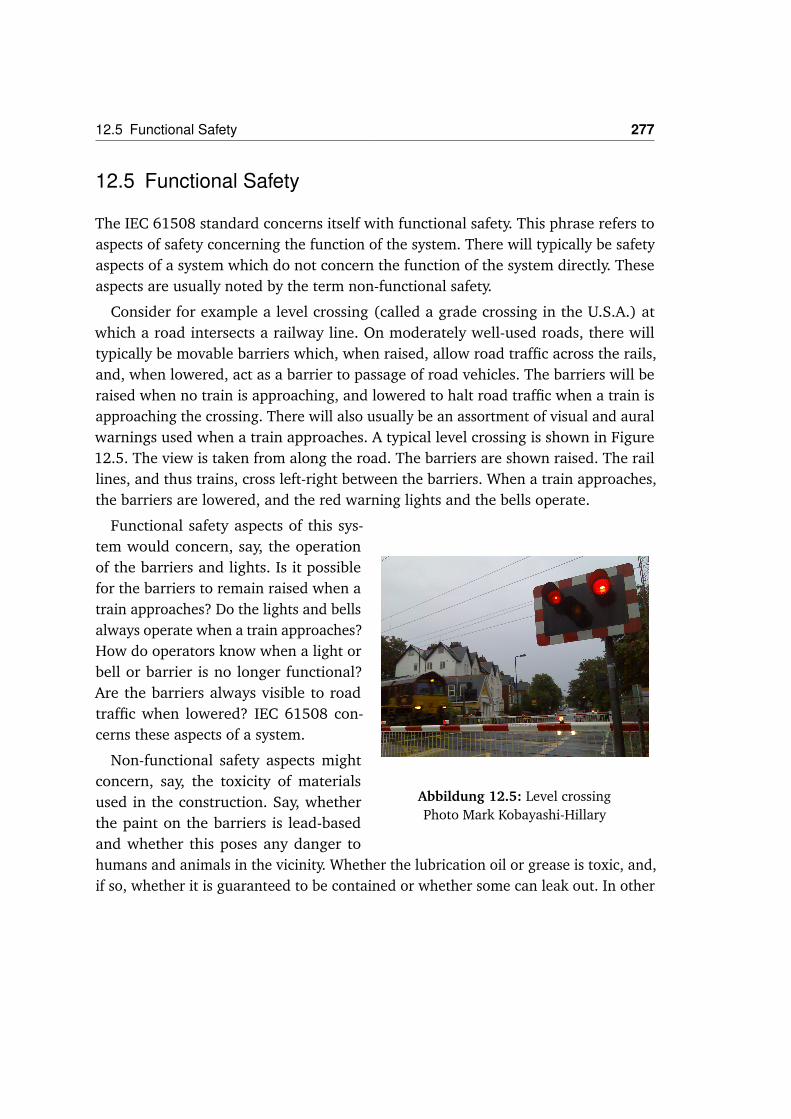
Consider for example a level crossing (called a grade crossing in the U.S.A.) atwhich a road intersects a railway line. On moderately well-used roads, there willtypically be movable barriers which, when raised, allow road traffic across the rails,and, when lowered, act as a barrier to passage of road vehicles. The barriers will beraised when no train is approaching, and lowered to halt road traffic when a train isapproaching the crossing. There will also usually be an assortment of visual and auralwarnings used when a train approaches. A typical level crossing is shown in Figure12.5. The view is taken from along the road. The barriers are shown raised. The raillines, and thus trains, cross left-right between the barriers. When a train approaches,the barriers are lowered, and the red warning lights and the bells operate.
Abbildung 12.5: Level crossingPhoto Mark Kobayashi-Hillary
Functional safety aspects of this sys-tem would concern, say, the operationof the barriers and lights. Is it possiblefor the barriers to remain raised when atrain approaches? Do the lights and bellsalways operate when a train approaches?How do operators know when a light orbell or barrier is no longer functional?Are the barriers always visible to roadtraffic when lowered? IEC 61508 con-cerns these aspects of a system.
Non-functional safety aspects mightconcern, say, the toxicity of materialsused in the construction. Say, whetherthe paint on the barriers is lead-basedand whether this poses any danger tohumans and animals in the vicinity. Whether the lubrication oil or grease is toxic, and,if so, whether it is guaranteed to be contained or whether some can leak out. In other
278 12 An Overview of IEC 61508 on E/E/PE Functional Safety
words, safety aspects of the system which are secondary to its intended function. Ofcourse, oil, grease and paint are essential to the correct functioning of the system,but the function of the system concerns solely when barriers and warnings operate,and when they do not, and when they should (and maybe when they should not).IEC 61508 is not concerned with the non-functional aspects such as toxicity of systemcomponents.
12.5.1 Assuring Functional Safety and Safety Functions
If it is found during the hazard and risk analysis of the system functions that aparticular aspect is too risky (we discuss below how this is determined), then thespecific risk must be mitigated or eliminated.
One way to do this is to redesign the system such that the specific risky aspect isno longer present. For example, at a road-rail crossing, if it cannot be determined toa satisfactory degree that barriers will always come down and lights flash and bellssound when a train approaches a level crossing, maybe one would build a road bridgeover the railroad instead.
Another way, emphasised by IEC 61508, is to provide additional functions whosepurpose is to intervene to mitigate the identified risk so that it becomes acceptable.Such a function is called a safety function in the standard. The definition is somewhatconvoluted:
Safety function : Function to be implemented ....... which is intended to achieve ormaintain a safe state for the EUC, in respect of a specific hazardous event
Here, the mitigation of the risk is phrased in terms of a „safe state“ for the Equip-ment under Control. But safety is not necessarily solely concerned with states, dividedinto „safe“ and „non-safe“, but also concerned with behavior. Although, indeed in theo-retical computer science a „safety property“ of a computational system is a partitionof the states of the system into two (which may be called „safe“ and „unsafe“).
Consider, for example, a car collision in which airbags are deployed and save thecar occupants from injury. Call this Case 1. Consider as well the exact same collision,with the same car and people at the same place, and the same dynamics, but this timewithout airbag deployment, and the occupants are seriously injured. Call this Case 2.Now, it would be reasonable to think that the airbags execute a safety function. Theycertainly have a function: to deploy and cushion in case of a sudden deceleration.

12.6 Risk and Risk Reduction 279
This function has also, obviously, a lot to do with avoiding harm, since the humanbody cannot tolerate decelerations of the sort that occur in substantial car collisionswithout airbags.
But the airbag deployment does not return the EUC to a safe state. Indeed, theEUC remains just as thoroughly totalled in Case 1 as is does in Case 2. So it looks asif airbag deployment is not a safety function in the sense of IEC 61508.
Let us look again at my above explanation of a safety function as one whose purposeis to intervene to mitigate the identified risk so that it becomes acceptable. We cancertainly say that Case 2 is a hazardous event, because it was a hazardous situationwhich resulted in harm: people were injured. This hazardous event has a certain riskassociated with it, namely its likelihood of occurrence combined with its severity. Theairbag deployment serves to reduce the severity of this hazardous event considerably,indeed in Case 1 to the point at which it is barely still a hazardous event accordingto IEC 61508 (let us suppose the occupants are badly shaken, so this still countsas harm). Having functioning airbags thus serves not to alter the likelihood of anyhazardous events that are collisions, but it serves to alter the severity of each of thoseevents. Thus it is a risk reduction measure (one factor in the risk calculation remainsthe same; the other is reduced). It mitigates the risk so that it becomes acceptable,and does so through affecting the second component of the risk calculation ratherthan the first.
So as a function to reduce risk to an acceptable level, the airbag deployment works.It may make sense to consider it and its brethren an „honorary safety function“ in anIEC 61508-conforming development.
12.6 Risk and Risk Reduction
The entire assessment of safety in IEC 61508 occurs through risk assessment andrisk reduction. In the hazard and risk analysis, hazardous events are identified andthe necessary risk reduction for these events determined. I discuss here how this isenvisaged to happen.
Apart from the definition of „risk“ which we have discussed, IEC 61508 says that„[r]isk is a measure of the probability and consequence of a specified hazardous eventoccurring“ (Part 5, Annex A: Risk and safety integrity - general concepts, ParagraphA5. The definitions explicitly refer to Part 5, Annex A for „discussion“, so we may

280 12 An Overview of IEC 61508 on E/E/PE Functional Safety
assume this is intended to be definitive). This suggests that the overall risk of using asystem, the de-Moivre-type risk, is not a concept to which IEC 61508 explicitly givesmuch credence. Consider the definition of „EUC risk“:
• EUC risk: risk arising from the EUC or its interaction with the EUC controlsystem
If we are to put together EUC risk with its explanation as a measure of the „proba-bility and consequence of a specific hazardous event“, we would say that EUC riskis a measure of some features of a specific hazardous event. Assuming there will bemany sorts of hazardous events, this does suggest that we are being led to considereach of them individually, and not aggregate as in a de-Moivre-type risk assessment.Indeed, the requirement in Part 1, Paragraph 7.4.2.7 is that
• 7.4.2.7 The EUC risk shall be evaluated, or estimated, for each determinedhazardous event. Given that the EUC risk has been determined for a specifichazardous event, there is now a requirement that
• 7.5.2.2 The necessary risk reduction shall be determined for each determi-ned hazardous event. The necessary risk reduction may be determined in aquantitative and/or qualitative manner.
This refers to the notion of „necessary risk reduction“:
• Necessary risk reduction: risk reduction to be achieved by the E/E/PE safety-related systems, other technology safety-related systems and external risk-reduction facilities in order to ensure that the tolerable risk is not exceeded
This process of determining risk reduction is summarised in Figure 12.6.
Let us consider a specific hazardous event, E, and suppose one has determined theEUC risk of E and the tolerable risk of E (in other words, what risk „society accepts“ ofE). Suppose further than the EUC risk of E is higher than the tolerable risk of E. Thenone must take steps to ensure that the risk of E in the overall system S is reduced to atmost the tolerable risk of E. The means envisaged by IEC 61508 for the risk reductionin the E/E/PE part is the introduction of functions which specifically reduce the riskof E, so that the risk of E in the operation of the system S’, where
S’ = EUC enhanced with the introduced functions
is at or below the tolerable risk of E. The risk of E in the operation of S’ is called
• Residual risk: risk remaining after protective measures have been taken

12.6 Risk and Risk Reduction 281
Tolerable risk
EUC risk
Necessary risk reduction
Actual risk reduction
Increasing
risk
Residual
risk
Partial risk covered by E/E/PE
safety-related systems
Partial risk covered by other technology
safety-related systems
Partial risk covered by external risk
reduction facilities
Risk reduction achieved by all safety-related
systems and external risk reduction facilities
Let us consider a specific hazardous event, E, and suppose one has determined the EUC risk of E and
the tolerable risk of E (in other words, what risk “society accepts” of E). Suppose further than the EUC
risk of E is higher than the tolerable risk of E. Then one must take steps to ensure that the risk of E in
the overall system S is reduced to at most the tolerable risk of E. The means envisaged by IEC 61508
for the risk reduction in the E/E/PE part is the introduction of functions which specifically reduce the
risk of E, so that the risk of E in the operation of the system S', where
! S' = EUC enhanced with the introduced functions
is at or below the tolerable risk of E. The risk of E in the operation of S' is called
! Residual risk: risk remaining after protective measures have been taken
The difference between the EUC risk and the residual risk is denoted in the diagram as the “actual risk
reduction”. This phrase has no formal definition, probably because it is clear what it means.
This analysis and prophylaxis is supposed to take place for each specific hazardous event.
Determination of Risk Reduction: Balancing the Options
Suppose one has performed a hazard analysis and identified a set of hazardous events and their
likelihoods and severities, as required in 7.4.2.
One of the ways in which one can deal with an identified hazard is to redesign the system to eliminate
it. Indeed, IEC 61508 requires
! 7.4.2.2 Consideration should be given to elimination of the hazards
18
Abbildung 12.6: Determining Risk Reduction
The difference between the EUC risk and the residual risk is denoted in the diagramas the „actual risk reduction“. This phrase has no formal definition, probably becauseit is clear what it means.
This analysis and prophylaxis is supposed to take place for each specific hazardousevent.
12.6.1 Determination of Risk Reduction: Balancing the Options
Suppose one has performed a hazard analysis and identified a set of hazardous eventsand their likelihoods and severities, as required in 7.4.2.
One of the ways in which one can deal with an identified hazard is to redesign thesystem to eliminate it. Indeed, IEC 61508 requires
• 7.4.2.2 Consideration should be given to elimination of the hazards
But suppose eliminating one hazard increases the risk of another hazardous eventnot associated with that hazard?

282 12 An Overview of IEC 61508 on E/E/PE Functional Safety
For example, a couple of decades ago, experiments were performed on an anti-misting kerosene (AMK) to be used in jet aircraft. The idea of the kerosene was toinhibit ignition of the fuel in the case of an aircraft accident. Indeed, the FAA believedit had identified 32 accidents between 1960 and 1984 in which AMK could havesaved lives1. A test was performed using a remote-piloted Boeing B720, which waslanded in the desert into a set of large steel „knives“, placed vertically in the ground,whose purpose was to slice into the tanks and release fuel into the atmosphere,and see what happened. The fuel ignited, but burned at a lower temperature thanotherwise expected, and less of it burned, thus giving potential passengers more timeto evacuate away from the aircraft. Nevertheless, the television coverage showed afireball and developments of AMK were effectively discontinued. Suppose indeed thatdevelopment of AMK had been continued. The fuel had different physical characte-ristics from the usual jet fuels, and new means of delivery, both from fuel tankersto aircraft, and from aircraft fuel tanks to engines, would have been required. So,suppose one had decided to eliminate the hazard of immediate conflagration in anaircraft accident by using AMK. How does one balance this against the increased riskof engine problems during flight, which would have been engendered by the changeof delivery technology required?
Consider another example. There has been a general trend over the last thirtyyears in new commercial aircraft design to replace mechanical control systems withelectrical/electronic control systems. One of the reasons for this has been to reduceoverall aircraft weight and to increase the ease of building the aircraft. However, it hasalso been argued that electrical/digital-technology control systems are actually morereliable than their forbears, inter alia because of the added ease of implementingfault-tolerance in such systems. However, putting more electrical wires into airplanes,bound together in wire bundles, increases the chances of insulation faults and arcingwithin and between electrical wires, so called „arc faults“, a phenomenon givenincreased prominence after the accident to TWA 800 in 1996 and to Swissair 111in 1998, and the ensuing investigations into wiring quality on commercial aircraft.How may one balance the potentially reduced risk of functional faults with electricalcontrol systems against the increased risk of arc faults and ensuing aircraft fires dueto the increase in required electrical wiring?
This example is particularly poignant because it involves exchanging a risk infunction (operational reliability of a control system) with a non-functional risk (awiring fire is a non-functional safety hazard, under the definition of functional/non-

12.6 Risk and Risk Reduction 283
functional we have seen above). So in this example the second risk, that of a wiringfire, is „invisible“ to IEC 61508 and therefore so is any trade-off of risk. IEC 61508would suggest to increase control-system reliability through moving to electrics andwould not necessarily recognise the increased wiring-fire hazard which it mightengender.
IEC 61508 gives no guidance on how one may proceed in such cases, nor indeed isthere any explicit recognition in the standard that such circumstances could arise.
There are a number of possible ways in which the convenors of IEC 61508 couldreply to the above queries. The most trivial would be to say that IEC 61508 doesnot cover commercial aviation; that would just be avoiding the question, but thisauthor has nevertheless heard such kinds of reply. A second reply would be to saythat the standard allows recognition of the situation, but neither explicitly recognisesthe situation nor offers guidance because there is no generally agreed way to proceed.It may be the case that there is no generally-agreed way to proceed, but this is sowith lots of other issues, such as when and how to apply so-called formal methodsin development and analysis, on which the standard does offer guidance: at least anexplicit recognition of the situation seems appropriate.
A third answer would be that the standard in fact does offer guidance, but implicitly,and that the guidance it does offer is not necessarily appropriate! As follows.
Let us suppose we have two hazards, H1 and H2. Say, H1 is the chance of immediate,deadly conflagration of jet fuel in the case of a tank rupture; and H2 is all enginescutting out in flight. IEC 61508 says to give consideration to eliminating the hazard.Suppose we do so, and eliminate hazard H1 (say, by introducing AMK into dailycommercial flight operations), and thereby increase the risk associated with H2(engines failing during cruise flight because of interactions because the fuel deliverysystems and the physical properties of the fuel argue with each other). The IEC 61508tells us we must look at hazardous events arising from H2, whose risk has beenincreased (through increasing the probability of occurrence of H2), and reduce therisk of those hazardous events to a tolerable level (to the „tolerable risk“ associatedwith the event). So it seems as if IEC 61508 might be telling us to eliminate hazardswhere possible, and then work harder to reduce the increased risk of others down totheir defined „tolerable level“.
But what about considering the joint risk of H1-events and H2-events? Althoughone has eliminated the risk of H1-events, maybe the „tolerable level“ associated with

284 12 An Overview of IEC 61508 on E/E/PE Functional Safety
H2 events is such that the risk of (H2-events with AMK) is higher than the joint risk of(H1-events without AMK) together with (H2-events without AMK). A risk reductionapproach associated with a de-Moivre-type risk would say that the joint risk is whatis most important and advise to reduce the joint risk as far as possible. This seemsthen to be an approach which is contra-indicated by IEC 61508 as written.
The possibility of reading IEC 61508 contrary to established reasonable approaches,such as the de-Moivre type, suggests that explicit guidance in IEC 61508 is necessary.And it is not there at the moment.
The core of this issue lies with the focus in IEC 61508 on risks of individual„hazardous events“, rather than on overall risk, as considered by a de-Moivre-typecalculation.
12.6.2 Risk Reduction and ALARP
IEC 61508 considers ALARP explicitly, in Part 5 Annex B, ALARP and tolerable riskconcepts.
The first observation to make is that, while IEC 61508 concerns itself with reducingrisk of infividual events, the ALARP principle encompasses overall risk. In the quandaryover how jointly to handle H1 and H2 above, ALARP would say to reduce the jointrisk (if it is „reasonably practicable“ so to do) rather than eliminated H1 and incurringthereby an increased risk of H2-events above that of the previous joint risk.
There have been various attempts to turn ALARP into a principle of engineering,and IEC 61508 Part 5 Annex B is just one of them. It seems wise, therefore, to reiteratethat ALARP is a principle of English law, not an engineering principle. It may be thatengineering principles can be devised that, say, would have avoided the cases in whichEnglish law decided that ALARP had been violated, but there is no a priori guaranteethat these principles exactly encompass all that case law has and will decide aboutALARP. It is with this caveat that we may consider how ALARP can guide engineers.
The guidance given in IEC 61508 Part 5 Annex B uses the diagram shown in Figure12.7.
This diagram, on the vertical axis, suggests the following
1.There are cases in which the risk is unacceptable, no matter what you do. Theengineering advice is: don’t go there except in „extraordinary circumstances“. 2.Thereare cases in which the risk is (socially) acceptable anyway. As an engineer, if you

12.6 Risk and Risk Reduction 285
There have been various attempts to turn ALARP into a principle of engineering, and IEC 61508 Part 5
Annex B is just one of them. It seems wise, therefore, to reiterate that ALARP is a principle of English
law, not an engineering principle. It may be that engineering principles can be devised that, say, would
have avoided the cases in which English law decided that ALARP had been violated, but there is no a
priori guarantee that these principles exactly encompass all that case law has and will decide about
ALARP. It is with this caveat that we may consider how ALARP can guide engineers.
The guidance given in IEC 61508 Part 5 Annex B uses a diagram:
Intolerable region
Broadly acceptable region
(No need for detailed working to demonstrate ALARP)
Negligible risk
Risk cannot be justified
except in extraordinary
circumstances
Tolerable only if further risk reduction is impracticable or if its cost is grossly disproportionate to the improvement gained
It is necessary to maintain assurance that risk remains at this level
The ALARP or tolerability region
(Risk is undertaken only if a benefit is desired)
As the risk is reduced, the less, proportionately, it is necessary to spend to reduce it further to satisfy ALARP. The concept of diminishing proportion is shown by the triangle.
This diagram, on the vertical axis, suggests the following
1. There are cases in which the risk is unacceptable, no matter what you do. The engineering
advice is: don't go there except in “extraordinary circumstances”.
2. There are cases in which the risk is (socially) acceptable anyway. As an engineer, if you are in
this region then you don't need to perform “detailed working” to demonstrate adherence to
ALARP.
3. There is a region in which ALARP affects your work as an engineer. You have no need to
reduce risk further than you have if:
- either it is impracticable to do so, or
- the cost of doing so is “grossly disproportionate” to the “improvement gained”.
Let us consider first Case 2. Suppose the risk is acceptable. But suppose for a certain amount of
available resources you could have reduced the risk further. The legal principle of ALARP seems to
require that you do so. However, the IEC 61508 guidance says “no need to perform detailed working to
demonstrate” this. This seems to be, at best, questionable advice. A lawyer might well advise
21
Abbildung 12.7: ALARP
are in this region then you don’t need to perform „detailed working“ to demonstrateadherence to ALARP. 3.There is a region in which ALARP affects your work as anengineer. You have no need to reduce risk further than you have if: - either it isimpracticable to do so, or - the cost of doing so is „grossly disproportionate“ to the„improvement gained“.
Let us consider first Case 2. Suppose the risk is acceptable. But suppose for a certainamount of available resources you could have reduced the risk further. The legalprinciple of ALARP seems to require that you do so. However, the IEC 61508 guidancesays „no need to perform detailed working to demonstrate“ this. This seems to be,at best, questionable advice. A lawyer might well advise „whatever you think of themagnitude of the risk, make sure your documents prove you’ve done everythingreasonable practicable to reduce it“. This suggests that „detailed working“ mightindeed be helpful, in contrast to Part 5 Annex B’s suggestion that there is „no need“.All kinds of random assertions are made in court trials: my view is that it is best to bewell prepared.

286 12 An Overview of IEC 61508 on E/E/PE Functional Safety
Case 3 is an interpretation of case law as it presently is in England. If it is impracti-cable to reduce risk further (and you can demonstrate to the satisfaction of the courtthat it is impracticable!) then indeed you have no need to reduce risk further. Thisadvice relies explicitly upon the finding of Lord Asquith of Bishopstone in Edwards vs.National Coal Board 1949, in which he said
„Reasonably practicable is a narrower term than Physically possible and implies thata computation must be made [] in which the quantum of risk is placed in one scaleand the sacrifice involved in the measures necessary for averting the risk (whetherin time, trouble or money) is placed in the other and that, if it be shown that thereis a great disproportion between them the risk being insignificant in relation to thesacrifice the person upon whom the obligation is imposed discharges the onus whichis upon him.“
This may be taken broadly to substantiate the advice given in the diagram above.But note there is also further advice in the diagram, that „as the risk is reduced, theless, proportionately, it is necessary to spend to reduce it further to satisfy ALARP“. Ido not know of a legal basis for this advice; neither does it follow from the finding ofLord Asquith.
The U.K. Health and Safety Executive explains its role thus: „HSE’s job is to protectpeople against risks to health or safety arising out of work activities.“ It was set upas a regulatory body by the Health and Safety at Work Act of 1974. It acts as the defacto regulator for complex safety-critical systems that are not otherwise regulated(for example, commercial aviation is otherwise regulated). HSE brings legal casesagainst companies deemed to have violated HSW. In deciding whether to bring suchcases, one factor HSE considers is, of course, whether a company has fulfilled its dutyto reduce risk ALARP, and HSE often uses IEC 61508 as a reference standard to testthis duty2. Thus is a strong connection made between ALARP and IEC 61508 in theU.K. through regulatory behavior.
12.7 Subsystem Types
There are three types of system and subsystem to which IEC 61508 continuouslyrefers:
Equipment under control (EUC).

12.8 Safety Integrity and Safety Integrity Levels (SILs) 287
EUC control system (EUCCS).
Safety-related system (SRS). A system which „both implements the required safetyfunctions needed to achieve or maintain a safe state for the EUC and is intended toachieve, on its own or with other E/E/PE safety-related systems, other technologysafety-related systems or external risk reduction facilities, the necessary safety integri-ty for the required safety functions.“ So an SRS implements the safety functions andis which includes amongst its purposes not only implementing safety functions butalso achieving the required safety integrity.
There is just one of EUC and EUCCS. There may be many SRSs. An SRS is requiredto mitigate any hazardous event for which the tolerable risk is lower than the EUCrisk, and there may be many such hazardous events.
Besides these three subsystem types, there is the fourth type, of
Subsystems which are none of the above
12.8 Safety Integrity and Safety Integrity Levels (SILs)
Safety integrity is a key concept in IEC 61508 and is defined as the reliability of anSRS:
• Safety integrity: probability of a safety-related system satisfactorily performingthe required safety functions under all the state conditions within a statedperiod of time E/E/PE SRSs are assigned a safety integrity level:
• safety integrity level (SIL): discrete level (one out of a possible four) for spe-cifying the safety integrity requirements of the safety functions to be allocatedto the E/E/PE safety-related systems, ....
The four safety integrity levels for so-called high demand or continuous-modesystems are logarithmically related, according to Table 12.1
NOTE See notes 3 to 9 below for details on interpreting this table.
The safety integrity refers not to failure but to dangerous failure:
• dangerous failure: [a] failure which has the potential to put the safety-relatedsystem in a hazardous or fail-to-function state

288 12 An Overview of IEC 61508 on E/E/PE Functional Safety
Safety Integrity High demand or continuous mode of operationLevel (Probability of a dangerous failure per hour)
4 10−9 to < 10−8
3 10−8 to < 10−7
2 10−7 to < 10−6
1 10−6 to < 10−5
Tabelle 12.1: Safety Integrity Levels
We recall that there is no definition of what a „hazardous state“ might be, but itmight well be a SRS state as a consequence of which hazardous situation ensues.There is likewise no definition of what a „fail-to-function state“ is, and here it isharder to guess. Is a fail-to-function state one in which the SRS engages in nodynamic behavior at all, or can it be a state in which the behavior of the SRS isdifferent from that specified or required? If it is a state in which the SRS engagesin no behavior (it is stopped), then it is easy to see how hazards arise. The SRS isrequired to implement one or more safety functions, and a safety function is specifiedbecause it has been determined that the EUC risk of a specific hazardous event isnot tolerable. The safety function is there to reduce this risk to a tolerable risk. If thesafety function is no longer active, then the EUC risk of this specific hazardous eventis not tolerable, so it is easy to understand how a failure which might lead to a SRSfailure to function (under this interpretation) could be termed „dangerous“.
I emphasise that the notion of SIL applies to the E/E/PE parts of a system. There hasbeen considerable discussion amongst safety-critical digital system engineers aboutthe adequacy of this notion as defined in IEC 61508, and many have considerablereservations about it. There are other notions of SIL used in other standards whichdo not necessarily suffer from the same disadvantages.
First, a SIL is an attempt to designate the criticality of an SRS implementing asafety function. It is an attempt to do so which retains a certain amount of simplicity,namely there are just a few „boxes“ into which any SRS function can be put. Thesimplicity is advantageous in that the categories are necessarily broad, so that it isnot necessary to try to estimate the exact reliability with which a safety functionis performed, but just to fit it into a general region. To have few categories whilecovering all the possibilities, one is drawn most obviously to some kind of logarithmic

12.8 Safety Integrity and Safety Integrity Levels (SILs) 289
scale, which is how the categories are indeed defined in the table.
However, as Martyn Thomas has pointed out, the categories are incomplete. Whatif you need a safety function F, but it only needs to be reliable to the point of onedangerous failure in ten thousand operational hours? That is a critical figure, and onethat is not necessarily easy to achieve, but yet it accrues to no SIL. IEC 61508 proffersguidance on what techniques are appropriate for developing an SRS with a specifiedSIL, but since the requirement for F corresponds to no SIL, there is correspondinglyno guidance. But there is no reason to think that the safety function F is any lesscritical to safety than any other safety function.
There may also appear to be an incompleteness at the other end. No failure ratelower than one dangerous failure in 109 hours of operation occurs in the SIL table.One reason for this is explained in Note 6 accompanying the table. The standard setsa lower limit of one dangerous failure in 109 hours of operation on the any dangerous-failure measure that can be claimed. So it does not allow anyone to claim lower thanthis in any circumstance. On the other hand, to achieve SIL 4, the table suggestsone has to show not only that a failure rate is lower than one dangerous failure in108 hours of operation, but also that more than or equal to one dangerous failuremust occur every 109 hours of operation, which seems perverse (as well as likelyindemonstrable). It would have been preferable simply to specify a probability ofdangerous failure per hour of „< 10−8“. We may hope this anomaly will be correctedin future revisions of the standard.
A fundamental disquiet with the notion of SIL used in the standard is the associationof a SIL with a set of recommended development techniques, for example, whetherthe use of formal methods is or is not recommended. So, for example, the use offormal methods such as CCS, CSP, HOL, LOTOS, OBJ, temporal logic, VDM and Z is„recommended“, but „only exceptionally, for some very basic components only“ forSIL 3 (Part 6, Table E.14). One can query the wisdom of this sort of advice, as follows.
A SIL of 3 requires a system attain a very, very low dangerous failure rate, betweenone in ten million and one in one hundred million hours of operation. Now, typicalsafety-critical code quality is about one error per thousand lines of source code (perKLOC: „Lines of code“ = LOC, thousand LOC = KLOC) (John McDermid, personalcommunication). Some organisations are able to attain measured quality of one errorin 25 KLOC by using highly-integrated formal methods while writing the programs(for example, the SPARK Ada system of the U.K. company Praxis High-Integrity

290 12 An Overview of IEC 61508 on E/E/PE Functional Safety
Systems). Others are able to attain one error per 4 KLOC on smallish systems, say afew tens of KLOC (see for example Les Hatton, Safer C, Addison-Wesley 1989). As iswell-known, the consequences of these errors in software can hardly be functionallybounded in advance. It is usually not possible to say with any degree of confidencehow the system will ultimately behave if a certain type of error occurs. It follows thata worst-case assumption is that each error in SRS software may result in a dangerousfailure, and it is rare to see how to do better than this worst-case assumption. Sothere is a wide gap between measured software quality, even using integrated formalmethods throughout development, and a requirement for dangerous failure suchas contained in SIL 3. Use of formal methods such as by Praxis seem to improvethe quality of delivered software by one to two orders of magnitude, but there isno known evidence that one can achieve SIL 3 reliability without using rigorousdevelopment techniques, as the standard suggests.
Indeed, even if there were such evidence, what could be a reason for not wishingsoftware to be as reliable as possible, even exceeding its SIL requirement?
One suspects that behind such advice lies the old canard about formal methodsconsume resources in great quantity when compared with the gain in quality thatthey enable. Against, one may observe that certain companies use formal methods inorder to produce software of higher quality with lower resource consumption. Sincethis can be done, it sets the state of the art and there is no reason not to recommend,indeed require, state-of-the-art quality-attainment methods in every critical softwaredevelopment, from SIL 0 (if it existed) through SIL 4.
In question here are two aspects of the association in IEC 61508 of developmentmethods (as „not recommended“, „recommended“ or „highly recommended“) withsoftware quality as represented in the SILs.
The first aspect is that, although one may reasonably expect particularly carefuldevelopment processes to result in software of higher quality, no association hasever been shown between the use of a specific development technique and a specificquality level of the resulting software, let alone for a range of development techniquesand the entire SIL quality-specification range.
The second aspect is that any association of specific methods with reliability rangesthat are powers of ten must be somewhat arbitrary. Even if such an association wereto be shown between, say, requirements analysis and specification in Z and rates ofdangerous failure in the range of less than 10−7 per operational hour, what reason

12.8 Safety Integrity and Safety Integrity Levels (SILs) 291
would we have to expect that such a boundary would lie at 10−7 rather than, say,12−7?
More obviously reasonable advice on association between development techniquesand SILs would surely be that one be free to use whatever development techniquesone thinks suitable, but that the results, in terms of the quality of delivered software,must be demonstrated to a high degree of confidence based on objectively goodevidence.
However, this runs up against the difficulty of what might constitute good evidence.In 1993, Littlewood and Strigini pointed out, for a Bayesian approach to evidence, andButler and Finelli for a frequentist approach, that assuring any failure rate (dangerousfailure or not) of below 10−5 per hour through statistical testing of a software systemwas infeasible. Indeed, Littlewood and Strigini observed that if you needed the resultof your testing to confirm a failure rate of 10−6 per hour or below, you had to gointo testing with a very good reason to claim (a prior probability in Bayesian-theoryterms) that you had achieved that rate already. And if you have that good reason inany case, why do all that testing?
There are serious issues here of evidence and achievement that cannot satisfactorilybe summarised in a few paragraphs, but constitute rather a research program. Itseems likely, though, that any anchoring of evidence to failure rates will have totake place at much higher failure rates than those envisaged in the SIL table in IEC61508. It seems certain that that table will have to be significantly modified. For thesereasons and others, many thoughtful engineers consider the requirements concerningSILs in IEC 61508 to be irrecoverably flawed.
12.8.1 Lowest Recognised Risk Reduction
We have noted that the standard sets a lower limit of one dangerous failure in109 hours of operation on the any dangerous-failure measure that can be claimed.There are at least two areas in which this lower limite may or must be exceeded. 1.Incommercial airplane certification, critical subsystems must be free of any single failurethat causes a catastrophic event (loss of the airplane, loss of life) to a level of at mostone in 109 operational hours. 2.In the automobile industry, it is well possible thatsome critical electronic components attain of the order of 1010 lifetime operationalhours3. Suppose they could be analysed and guaranteed down to one dangerous

292 12 An Overview of IEC 61508 on E/E/PE Functional Safety
failure 109 operational hours, the lowest level recognised by IEC 61508.Then, as faras one could tell, there would still be of the order of 10 critical events during thesystem life.
One may well query whether it is wise to have a standard that does not allow useven to express a measure of one dangerous failure, or more generally discriminatethis case from that of ten dangerous failures, in the operational life of a particularsystem.
12.8.2 Relationship between SILs and ALARP
Felix Redmill has elucidated the relationship between SILs and the ALARP princi-ple for U.K. engineers (Proceedings of the 8th Safety-Critical Systems Symposium,Southampton, U.K., Spinger-Verlag London, 2000).
Redmill pointed out that a SIL is an a priori requirement, which is defined andallocated in the Safety-Requirements-Analysis task during development. However,ALARP is a dynamic requirement that is assigned and handled in the task of Design,when designing and building the system is underway. He concludes that in someparticular case the ALARP principle could well require a reduction in risk beyond thatrequired by the SIL for a function.
This observation is astute, but to date no examples of this phenomenon haveappeared in the literature. One may also further observe that, since the HSE considerALARP to be satisfied if IEC 61508 has been followed during system development,that no further evidence would be required by the regulator that ALARP has beenfollowed than by exhibiting the derived SIL and the evidence for its attainment.
12.9 Appropriate and Inappropriate Applications of the IEC61508 Approach
With some understanding of the basic concepts behind IEC 61508, we may nowlook at some possible applications and see how and whether the standard fits thoseapplications conceptually.

12.9 Appropriate and Inappropriate Applications of the IEC 61508 Approach 293
12.9.1 Safety Functions
We have seen that achieving risk reduction through safety functions may not alwaysbe the most appropriate way to reduce risk.
An appropriate application
An example of an appropriate application of a safety function is the interlock onBoeing B767 aircraft (as well as many others) which prevents in-flight deploymentof reverse thrust. The normal thrust on a jet aircraft comes from the air and othergases expelled out of the rear of the engine. Reverse thrust is a mechanism to helpdeceleration on the runway during landing. A thrust reverse mechanism can be oneof two types, „clamshell“ (Figure 12.8a) or „cascade“ (Figure 12.8b).
(a) Clamshell Type (b) Cascade Type
Abbildung 12.8: Deployed Thrust Reversers
Two parts of the cowling rotate into the thrust stream and mechanically deflectit upwards/downwards and, most importantly, somewhat forwards. This forwards-directed component of thrust helps brake the aircraft on the runway during landing.A thrust reverse mechanism of the „cascade“ type is not quite as visible, since thethrust stream is reversed this time inside the cowling and exits midway. A cascadereverser works on the thrust stream essentially the same way as a cascade reverser.
On many if not most modern jet aircraft, thrust reverser deployment in flight almostinevitably leads to loss of control of the aircraft, which is defined as a „catastrophic“event in commercial aviation certification terms. So such an event would count as

294 12 An Overview of IEC 61508 on E/E/PE Functional Safety
a hazard, and it can be eliminated through inhibitory mechanisms. On the BoeingB767 aircraft, there is a hydromechanical mechanism which physically prevents thethrust reverse mechanism from operating when the landing gear is not deployedand there is not weight on the main landing gear (known as a „weight on wheels“or WoW criterion). WoW may be determined in a number of ways, most of whichinvolve sensing main landing gear strut movement as the aircraft weight compressesthe shock absorbers.
In May of 1991, a Lauda Air Boeing B767 crashed over Thailand. It was determinedthat thrust reverse had been electrically commanded (the crew spoke of the deploy-ment warning light illuminating on the cockpit voice recorder) and the subsequentradar track showed a loss-of-control descent consistent with thrust reverse havingactually been deployed on the affected engine. However, there was no failure modeknown of the interlock mechanism, the safety function as IEC 61508 would have cal-led it. Subsequent tests discovered such a failure mode. The rubber-compound sealson the interlock hydraulics became brittle with time, and could partly disintegrate,leaving hard rubber particles in the hydraulic fluid. These particles could becomelodged in a valve in the interlock mechanism, preventing it from closing fully when itneeded to, and thus inhibiting the interlock function. Since at least one failure modeof the interlock mechanism had been demonstrated, it was thereby known that theinterlock could fail and thus that in-flight thrust reverse, while unlikely, was possible.Deployment of the left engine thrust reverser in flight, leading to loss of control, wasdesignated as the probable cause by the accident investigators.
An inappropriate application
The ground spoilers and thrust reversers on the Airbus A320 aircraft are used, alongwith wheel brakes, to brake the aircraft on the runway. We have discussed thrustreverse, which is actually a minor braking effect (but which becomes significant whenthe runway is slippery, say when very wet or icy). Ground spoilers dump the lift onthe wings, putting the aircraft weight on the wheels and enabling effective wheelbraking. Ground spoilers are deployed and thrust reverse enabled on landing throughdigital logic involving the WoW criterion.
In September 1993, an Airbus A320 landed fast on a very wet runway in Warsawjust after passage of a thunderstorm with accompanying wind shear (which thepreviously landing aircraft had experienced a minute or so earlier). Upon touchdown,

12.9 Appropriate and Inappropriate Applications of the IEC 61508 Approach 295
ground spoilers should have deployed automatically, and reverse thrust was alsocommanded. However, neither functioned for some 9 seconds (and the wheel brakesnot for 13 seconds). The aircraft ran off the end of the runway, hit an earth bank,and burned. Two people lost their lives, but all others, passengers and crew, escapedwithout injury.
Abbildung 12.9: Deployed Spoilers of anAirbus A319
The inhibition of ground spoilers andreverse thrust during flight has the sa-me justification on the A320 as on theBoeing B767. As we have seen, reverse-thrust inhibition proceeds on the B767through an explicit safety function, na-mely an interlock mechanism. On theAirbus A320 family, this inhibition is ac-complished through digital logical condi-tions, which signals also have other func-tions and effects. It seems inappropriateto speak of implementing a „safety func-tion“ here. Rather, it seems preferable tospeak of a safety requirement being sa-tisfied through the design of the digitallogic.
Risk Reduction
We have seen that risk reduction is the main mechanism through which IEC 61508enhances safety.
An appropriate application
Consider an anti-lock braking system, an ABS, on a road car. In terms of IEC 61508concepts, the system components are as follows.
the EUC is the brakes the EUCCS is the brake activation mechanism, from pedal tobrake pads the SRS is the wheel-rotation sensors and the responsive brake-release-and-reapply mechanism
The EUC risk we can take as known, similarly the tolerable risk, so one can calculatethe required risk reduction and transform this requirement into a SIL according tothe SIL table. Then one demonstrates that the ABS fulfils the SIL.
296 12 An Overview of IEC 61508 on E/E/PE Functional Safety
Note that IEC 61508 is not applied in this way. Designers wish to allow the car tobe driven also when the ABS does not function. So ABS is not designated as an SRS(which must always be active) but rather as a functional enhancement which is notformally safety-related. So this example is conceptual. I chose it because it is ratherclear.
An inappropriate application
This section owes a considerable debt to the discussion in Derek Fowler’s paperApplication of IEC 61508 to Air Traffic Management and Similar Complex CriticalSystems, published in Lessons in System Safety, Proceedings of the Eighth SafetyCritical Systems Symposium, ed. Felix Redmill and Tom Anderson, Springer-Verlag,London 2000.
Consider air traffic control. The purpose of air traffic control is to avoid mid-aircollisions between participating aircraft by maintaining a specified amount separationbetween the aircraft, while enabling each aircraft to continue towards its destinationand landing. The IEC 61508 subsystems in air traffic control would be as follows.
the EUC is the air traffic itself: all participating aircraft the EUCCS is Air TrafficManagement (ATM), that is, the procedures contained in the laws of flight plus thecentralised planning that results in the Flight Plan for each participating aircraftthe SRS is the dynamic control exercised by the controllers with whom the aircraftcrews talk when under way: Air Traffic Control (ATC). The controllers modify theplanned flights of the participating aircraft dynamically, to ensure that separation ismaintained.
But now we run into some difficulty concerning the necessary estimates of riskaccording to IEC 61508.
EUC risk. This would be the probability of collision with ATM, but without ATC. ButATC historically has been present since there has been a significant risk of collisionamongst air traffic, certainly under all modern traffic and ATM conditions. So thereare no statistics at all by which to judge EUC risk Tolerable risk would be given by theTarget Level of Safety (TLS), a certain probability of collision. This can be and hasbeen set by ATC specialist organisations when needed The question then arises of howmuch risk reduction needs to be achieved by ATC over that provided by ATM? (The„required risk reduction“ of IEC 61508.) This question likely cannot be answered;

12.9 Appropriate and Inappropriate Applications of the IEC 61508 Approach 297
indeed it may not seem appropriate even to ask it. One has no idea of the relativecontributions of ATM and ATC to the TLS.
So it seems as if air traffic management and control is not a suitable area in whichto apply the risk-reduction concepts of IEC 61508 without considerable alteration inthe foreseen approach.
12.9.2 Safety Integrity Levels
An appropriate application
Consider what is called on British trains the Driver’s Safety Device, or „dead man’shandle“. This is a device which must be continually activated by a train driver, andmay be a pedal or a lever, or some other such device
Safety Integrity Levels
An appropriate application
Consider what is called on British trains the Driver's Safety Device, or “dead man's handle”. This is a
device which must be continually activated by a train driver, and may be a pedal or a lever, or some
other such device
A “dead man's handle” on a suburban train
The device on British trains is a lever with a red knob, which must be kept continually depressed by the
driver's hand when the train is running. If it is released, after a second or two emergency brakes are
automatically applied. The device is there to ensure that, if the driver becomes incapacitated for any
reason (stroke or heart attack, say), the train will be brought immediately to a stop.
In January 2003, near Waterfall, New South Wales, Australia, a train driver suffered a heart attack but
the “dead man's brake” did not activate. The train derailed, killing seven people on board including the
driver. A brief description of the accident may be found at http://en.wikipedia.org/wiki/Waterfall_train_disaster
The statistics on train drivers being incapacitated are, obviously, known in detail by every rail authority.
These authorities also set tolerable risk, or Target Levels of Safety. The required risk reduction can
therefore be determined, and from this the SIL of the Driver Safety Device may be read off.
Indeed, the dead man's handle implements an on-demand function which is triggered less than once a
year, system-wide. A designation of SIL 4 for an on-demand function requires that it be more reliable
than one failure in 10,000 applications (the SIL table for on-demand safety functions is different from
that for continuous functions which we discussed above). This would translate, then, to a condition that
the safety function provided could fail once every 10,000 years. That is obviously unnecessarily
stringent. The device could be happily designed to an on-demand SIL 2 or SIL 3 requirement.
More details on the device may be found at http://en.wikipedia.org/wiki/Dead_man's_switch
An inappropriate application
31
Abbildung 12.10: A „dead man’s handle“ ona suburban train
The device on British trains is a leverwith a red knob, which must be kept con-tinually depressed by the driver’s handwhen the train is running. If it is released,after a second or two emergency brakesare automatically applied. The device isthere to ensure that, if the driver beco-mes incapacitated for any reason (strokeor heart attack, say), the train will bebrought immediately to a stop.
In January 2003, near Waterfall, NewSouth Wales, Australia, a train driversuffered a heart attack but the „deadman’s brake“ did not activate. The trainderailed, killing seven people on boardincluding the driver. A brief descripti-on of the accident may be found athttp://en.wikipedia.org/wiki/Waterfall_train_disaster
The statistics on train drivers being incapacitated are, obviously, known in detail byevery rail authority. These authorities also set tolerable risk, or Target Levels of Safety.The required risk reduction can therefore be determined, and from this the SIL of the

298 12 An Overview of IEC 61508 on E/E/PE Functional Safety
Driver Safety Device may be read off.
Indeed, the dead man’s handle implements an on-demand function which is trig-gered less than once a year, system-wide. A designation of SIL 4 for an on-demandfunction requires that it be more reliable than one failure in 10,000 applications(the SIL table for on-demand safety functions is different from that for continuousfunctions which we discussed above). This would translate, then, to a condition thatthe safety function provided could fail once every 10,000 years. That is obviouslyunnecessarily stringent. The device could be happily designed to an on-demand SIL 2or SIL 3 requirement.
More details on the device may be found athttp://en.wikipedia.org/wiki/Dead_man’s_switch
’subsubsectionAn inappropriate application
An inappropriate application is represented somewhat trivially by the thrust-reverser interlock mechanism discussed above. Certification requires a failure proba-bility of less than 10−9 per operating hour, whereas the most stringent SIL allowed bythe IEC 61508 standard is a failure probability of between 10−8 and 10−9 per hour.
Another inappropriate application is represented by the air traffic control systemdiscussed above. There are many independent ATC subsystems, say of the order ofsome hundred. These subsystems can be classified, at the highest possible, at SIL 4.However, the entire system, consisting of 100 or more independent subsystems, canthen only be shown to satisfy at most SIL 2 (100 x 10−9 = 10−7). However, typicalTLS’s for air traffic control are in the range of a probability of dangerous failureper hour of 10−8 or lower. Again, I am indebted to Derek Fowler, op. cit., for thisobservation.
12.9.3 Difficulties with Applying ALARP
To show that IEC 61508 is not alone in its conceptual difficulties, we can considerhow ALARP may fare.
An appropriate application
Consider a SIL 1 programmable electronic subsystem, say implemented on a FieldProgrammable Gate Array (FPGA). Its functional-dangerous-failure probability requi-

12.9 Appropriate and Inappropriate Applications of the IEC 61508 Approach 299
rement lies in the region of one every 10,000 operating hours, which is about onceper year of continual operation (a year is typically taken by system engineers to be10,000 hours, more or less. It is actually some 8,760 hours, or 8,784 hours in a leapyear). Say one took 4,000 of these FPGAs and ran them continuously with inputsspanning the entire projected operating range for some 3 months, without a failure.Then one has accumulated failure-free experience of the order of some ten millionoperating hours, and Bayesian statistical calculations from this statistical testing allowone to form a high degree of confidence that the dangerous-failure requirement ofone failure every 10,000 hours is fulfilled.
An inappropriate application
Consider now a digital-logic-based flight control system (DFCS) for an aircraft. Sincefailure of flight controls can lead to loss of control, considered a „catastrophic“ event,this system must be required to be reliable to the order of one failure in 109 operatinghours, a failure probability of 10−9 per operating hour. The quantity of 109 operatinghours has never been exceeded by any fleet of commercial aircraft of a single model,so this says that such a failure may not be expected in the fleet life of the aircraft.
But there is no corresponding requirement on maintenance procedures. In March2001, an Airbus A320 aircraft departing Frankfurt was found to be cross-controlled,that is, when the pilot flying applied right bank to correct a left wing dip on take-off,he exacerbated the left wing dip and the wing came within a couple of meters ofhitting the ground. Luckily, the non-flying pilot noticed what was happening andhis control was not crossed, so he was able to recover, by deploying the take-overcommand button and flying the aircraft himself.
In other words, although risk had been reduced as far as reasonably practicable onthe design of the DFCS, it had certainly not been reduced as far as practicable on themaintenance, which cross-wired the captain’s control for bank, and failed to detectthe error during post-maintenance control checks. the ALARP principle applies todesign, and not necessarily to maintenance, although of course there are other legalprinciples, such as duty of care which occur under the various concepts of negligence,that would apply should an accident occur through maintenance mistakes and shouldit be decided to process such an event through the legal system.


![IEC 61508 and ISO 13849 Assessment - Precision Sensors · 2020. 2. 7. · IEC 61508 Site Audit Report, Precision Sensors [R3] Precision Sensors Final Safety Case IEC 61508 SafetyCaseDB](https://static.fdocuments.net/doc/165x107/60b0c617d7840d54fe30fb1a/iec-61508-and-iso-13849-assessment-precision-2020-2-7-iec-61508-site-audit.jpg)
