Kansas City Kansas School District · Kansas City Kansas School District Project Manual IFB 16-055...
124
Kansas City Kansas School District Project Manual IFB 16-055 Main Library 2017 Roofing Project December 2016 USD #500 2010 North 59 th Street Kansas City, Kansas 66114
Transcript of Kansas City Kansas School District · Kansas City Kansas School District Project Manual IFB 16-055...

Kansas City Kansas School District
Project Manual
IFB 16-055Main Library 2017 Roofing
Project
December 2016
USD #500 2010 North 59th Street
Kansas City, Kansas 66114

USD #500 December 2016 2017 Main Library Roofing Project
TABLE OF CONTENTS 00010 - 1
DOCUMENT 00010 - TABLE OF CONTENTS
DIVISION 00 BIDDING REQUIREMENTS AND CONTRACT FORMS Section 00010 Table of Contents Section 00101 Invitation to Bid Section 00201 Instructions to Bidders Section 00411 Bid Form and Attachment A
DIVISION 1 - GENERAL REQUIREMENTS
Section 01100 Summary Section 01330 Submittal Procedures Section 01700 Execution Requirements Section 01770 Closeout Procedures
DIVISION 2 (NOT APPLICABLE)
DIVISION 3 – CONCRETE
Section 03931 Concrete Deck Rehabilitation
DIVISION 4 (NOT APPLICABLE)
DIVISION 5 - METALS
Section 05310 Steel Deck
DIVISION 6 - WOOD AND PLASTICS
Section 06105 Miscellaneous Carpentry
DIVISION 7 - THERMAL AND MOISTURE PROTECTION
Section 07501 Aliphatic Polyurethane Roofing Section 07511 Cold Applied Built-Up Roofing Section 07541 Tri-Polymer Alloy Roofing Section 07591 Membrane Reroofing Preparation Section 07620 Sheet Metal Flashing And Trim
DIVISION 8 – 16 (NOT APPLICABLE)
DETAIL DRAWINGS
ROOF PLANS
END OF DOCUMENT 00010

USD #500 December 2016 2017 Main Library Roofing Project
INVITATION TO BIDDERS 00101 - 1
DOCUMENT 00101 – INVITATION TO BID
PROJECT: 2017 Roof Replacement Projects
LOCATION: Main Library - Kansas City Kansas Public Schools OWNER: Unified School District #500
The Owner will receive sealed bids until the bid time and date at the location given below for the following Work: Roof Replacement on miscellaneous buildings as listed in Specification Documents.
BID SUBMITTAL AND BID SECURITY The Owner will consider bids as listed above, prepared in compliance with the Instructions to Bidders issued by the Owner, and delivered as follows: Bid Date: December 22, 2016 Bid Time: 1:00 p.m., local time. Location: Bids to be mailed or hand delivered to the following address:
Attn: Mr. Robert Young, Director - Purchasing 2010 North 59th Street Third Floor – Conservatory Room Kansas City, Kansas 66104
Faxed bids are not acceptable.
The Owner (USD #500) reserves the right to accept or reject any and all bids and reserves the right to final judgment as to awarding the bid.
PRE-BID CONFERENCE A pre-bid conference for all bidders will be held at District Maintenance Shop, 2220 N. 59th, Suite 229, Kansas City, Kansas 66104 on December 6 and 7, 2016 at 9:00 a.m., local time. All prospective bidders are required to attend.
DOCUMENTS Bidding documents may be obtained during the pre-bid. Documents will be provided to prime bidders only; only complete sets of documents will be issued.
TIME OF COMPLETION Bidders shall begin work upon receipt of Notice to Proceed and to complete the work within the Contract Time indicated in the Contract Documents.
BIDDER’S QUALIFICATIONS Bidders must be properly licensed under the state laws governing their respective trades and be able to obtain insurance and bonds required for the Work.
END OF SECTION 00101

USD #500 December 2016 2017 Main Library Roofing Project
INSTRUCTIONS TO BIDDERS 00201 - 1
DOCUMENT 00201 – INSTRUCTIONS TO BIDDERS
1.1 ADVERTISEMENT FOR BIDS
A. An Invitation to Bid, published as a separate document, is part of these instructions.
1.2 DEFINITIONS
A. Bidding Documents include the Bidding Requirements and the proposed Contract Documents.The Bidding Requirements consist of the Advertisement for Bids, these Instructions to Bidders,bid forms, and other sample bidding and contract forms. The proposed Contract Documentsconsist of the form of Agreement between the Owner and Contractor, Conditions of theContract, Drawings, Specifications, and all Addenda issued prior to execution of the Contract.
B. Addenda are written or graphic instruments issued by the Owner prior to the execution of theContract that modify or interpret the Bidding Documents.
C. The Base Bid is the sum stated in the Bid for which the Bidder offers to perform the Workdescribed in the Bidding Documents as the base, to which Work may be added or from whichWork may be deleted for sums stated in Alternate Bids.
D. An Alternate Bid is an amount stated in the Bid to be added to or deducted from the amount ofthe Base Bid if the corresponding change in the Work, as described in the Bidding Documents,is accepted.
E. A Unit Price is an amount stated in the Bid as a price per unit of measurement for materials,equipment, or services, or a portion of the Work as described in the Bidding Documents.
F. A Bidder is a person or entity who submits a Bid to the Owner and who meets the requirementsset forth in the Bidding Documents.
1.3 BIDDING DOCUMENTS
A. Obtaining Bidding Documents: Bidders may obtain complete sets of the Bidding Documentsfrom the issuing office designated in the Advertisement for Bids in the number and for the costor deposit sum, if any, stated therein. Bidders shall use complete sets of Bidding Documents inpreparing Bids. The Owner assumes no responsibility for errors or misinterpretations resultingfrom the use of incomplete sets of Bidding Documents.
B. Examination of Bidding Documents and Site: Before submitting a bid, the Bidder shall carefullyexamine the drawings, read the specifications and all other Contract Documents and visit thesite of the Work. The Bidder shall fully inform himself prior to bidding as to all existingconditions and limitations under which the Work is to be performed and he/she shall include inthe Bid a sum to cover the cost of all items necessary to perform the Work as set forth in theContract Documents. No allowance will be made to the Bidder because of lack of suchexamination or knowledge. The submission of a bid shall be construed as conclusive evidencethat the Bidder has made such examination.

USD #500 December 2016 2017 Main Library Roofing Project
INSTRUCTIONS TO BIDDERS 00201 - 2
C. Interpretation or Correction of Bidding Documents: If the Bidder is in doubt as to the interpretation of any part of the Bidding Documents, or finds discrepancies in or omissions from any part of the Contract Documents, he/she must submit a written Request for Interpretation thereof not later than 7 days prior to opening of bids. Address all communications to the Owner.
1.4 ADDENDA
A. Any interpretation, correction to, or addition to the Contract Documents will be made by written Addendum and will be delivered by mail or fax to each prime Bidder of record and the plan services indicated in the Advertisement for Bids. The written Addenda constitute the only interpretations of the Contract Documents; the Owner accepts no responsibility for any other claimed interpretations.
B. It is the responsibility of each Bidder to verify that he/she has received all Addenda prior to submitting a bid. It is also the responsibility of each Bidder to verify that all sub-Bidders and material suppliers whose prices are incorporated in the Bidder’s bid are familiar with the Bidding Documents in their entirety, including all Addenda issued up to the time of bid opening.
C. In the event a conflict or omission is discovered in the Bidding Documents after the issuing of the last addendum such that an interpretation cannot be issued by the Owner prior to bidding, the Bidder is directed to estimate on and provide the quantity and quality of material and labor consistent with the overall represented work so as to provide all materials, equipment, labor, and services necessary for the completion of the Work.
1.5 SUBSTITUTIONS DURING BIDDING
A. Substitutions are not allowed during bidding. Bids shall be submitted based upon the materials, equipment, and services specified.
1.6 BIDDING PROCEDURES
A. Form Of Bid 1. Bids must be submitted on the Bid Form provided, properly executed and with all items
filled out in ink or typed. Do not change or add words to the Bid Form. Unauthorized conditions, limitations, or provisions on or attached to the Bid Form may be cause for rejection of the bid. Bidder’s information on the Bid Form that is altered by erasure or by interlineation prior to submittal must be initialed and explained by notation on the Bid Form above the signature of the Bidder. All signatures must be witnessed.
B. Submission Of Bids 1. Each bid shall be delivered to the location indicated on the Bid Form on or before the day
and hour set for receipt and opening of bids. Each bid shall be submitted in an opaque, sealed envelope marked in the lower left-hand corner as follows:
Bid for (name of prime contract) Name of Project Bidder's Name

USD #500 December 2016 2017 Main Library Roofing Project
INSTRUCTIONS TO BIDDERS 00201 - 3
Bidder's Address Contractor's License No. Date and Time of Bid Opening
2. If not delivered in person, this envelope shall be enclosed in a second envelope for
posting to the location indicated for receipt of bids. This envelope shall be addressed as follows:
Bid for (name of prime contract)
Owner name
Street address OR Post Office Box 0000
City Name, State, Zip Code Contractor's License No. Date and Time of Bid Opening
3. It is the sole responsibility of the Bidder to see that his/her bid is received in proper time.
No bids submitted after the time fixed for receiving bids will be considered; late bids will be returned to the Bidder unopened.
C. Acknowledgement Of Addenda 1. Bidder must acknowledge all Addenda received in the spaces provided on the Bid Form.
By submitting a bid, Bidder indicates that all considerations issued by addendum are incorporated in the bid.
D. Bid Supplements 1. Attached to the Bid Form will be certain supplements that are included in this Project
Manual following the Bid Form. Bidders shall complete all forms, entering “Not Applicable” where information does not apply to their portion of the Work. Absence of any of the Bid Supplements included in the Project Manual will be reason for possible rejection of bid.
E. Status Of Bidders 1. Proprietors submitting bids shall indicate their status as proprietors. 2. Bidders submitting bids for partnerships shall indicate their status as partners and shall
submit, upon request of the Owner within 24 hours following receipt of bids, a certified copy of the power of attorney authorizing the executor of the bid to bind the partnership.
3. Bidders submitting bids for corporations shall indicate their status as corporations and shall submit, upon request of the Owner within 24 hours following receipt of bids, a certified copy of the board of directors’ authorization for the Bidder to bind the corporation and shall affix the corporate seal on the bid.
4. Bidders shall provide, upon request of the Owner, within 24 hours following receipt of bids, the following: a. Names and addresses of proprietors, of all members of a partnership, or of the
corporation’s officers. b. Name of county or state where the partnership is registered or where the
corporation is incorporated. Corporations must be licensed to do business in the project state at the time of executing the contract.

USD #500 December 2016 2017 Main Library Roofing Project
INSTRUCTIONS TO BIDDERS 00201 - 4
1.7 MODIFICATION AND WITHDRAWAL OF BIDS
A. A bid may be withdrawn on personal requests received from Bidder prior to submission time. A withdrawn bid may be resubmitted up to submission time. Negligence or error on the part of the Bidder in preparing his/her bid confers no right for withdrawal of the bid after it has been opened.
B. Telegraphic and faxed bids will not be considered.
C. No Bidder may withdraw a bid within 60 days following the opening of bids.
1.8 AWARD OR REJECTION OF BIDS
A. The contract, if awarded, will be awarded to the lowest responsible Bidder, subject to the Owner's right to reject any or all bids and to waive any informality in the bids or in the bidding. Failure to complete all information required on the Bid Form and Bid Form Supplements, may result in rejection of bid. The Owner shall have the right to accept alternates in any order or combination, unless otherwise specifically provided in the Bidding Documents, and to determine the low bidder on the basis of the sum of the Base Bid and Alternates accepted.
B. Bids may be rejected if the Bid Form shows any unexplained erasures, omissions, alterations of form, additions not called for, added restrictions or qualifying conditions or other irregularities of any kind.
C. The Owner may make such investigations as he/she deems necessary to determine the ability of the Bidder to perform the Work, and the Bidder shall furnish to the Owner all such information for this purpose as the Owner may request. The Owner reserves the right to reject any bid if the evidence submitted by or investigation of such Bidder fails to satisfy the Owner that such Bidder is properly qualified to carry out the obligations of the Contract and to complete the Work contemplated therein within the Contract Time.
1.9 ACCEPTANCE
A. The acceptance of a bid will be a Notice of Award, signed by a duly authorized representative of the Owner; no other act by the Owner or his/her agents shall constitute the acceptance of a bid. The acceptance of a bid by the Owner shall bind the successful Bidder to execute the contract. The Bidder to whom the contract is awarded by the Owner, shall, sign and deliver to the Owner for execution by the Owner all required copies of the Agreement, along with all required insurance and bonding documents. The rights and obligations provided for in the Contract shall become effective upon the parties only with formal execution of the Agreement by the Owner.
1.10 BONDS AND CERTIFICATES
A. Bid shall be accompanied by an acceptable bid bond or certified cashier's check drawn on a local bank, payable to Treasurer, Board of Education, for an amount not less than five percent of the total amount of the bid. This bid security shall become the property of the Board of Education as liquidated damages in the event the successful bidder fails to execute and deliver a

USD #500 December 2016 2017 Main Library Roofing Project
INSTRUCTIONS TO BIDDERS 00201 - 5
contract, along with specified surety and statutory bonds, within ten days after the received notice of the acceptance of his bid by the Board of Education.
B. Bidder shall deliver to the Owner, upon receipt of contract or purchase order, a Performance Bond, a Payment Bond, and a Labor and Material Bond, each in the amount of 100 percent of the Contract Sum, with a corporate surety authorized to transact business in the Project State, within 3 days following execution of the Contract, or prior to commencement of the Work, whichever occurs first. Attorneys-in-fact who sign bonds must file with each bond a certified and effective dated copy of their power of attorney.
C. Satisfactory certificates of insurance in the amounts specified in the Contract Documents shall be furnished prior to commencement of Work.
D. All bonds and policies or certificates of insurance must meet with the approval of the Owner before the Contractor will be allowed to commence the Work. Failure or refusal to furnish bonds or insurance policies or certificates in a form satisfactory to the Owner shall subject the Bidder(s) to forfeiture of bid bond.
E. The form of the Agreement that the successful Bidder, as Contractor, will be required to execute is the form of Agreement referenced in the Project Manual.
1.11 INVOICING AND OFFICE SUPPORT
A. All bidders must have the ability within their office to process all required paperwork for invoicing the District. This is to include, but not be limited to, timely issuance of invoices with proper backup to support the amount due, certified payrolls/reports, and all required closeout documents.
B. Invoices may be emailed IF the contents of the email contain a cover letter with the invoice amount and all necessary support backup for the total amount due.
C. All tax exempt “completion forms” must be provided to the District within the State of Kansas required timeframe. Violation of this process point might negate the tax free benefit of working with the District.
1.13 LIQUIDATED DAMAGES
A. Liquidated Damages: In the event Contractor fails to complete the work in accordance with the
Schedule specified in the Agreement or within such additional time(s) as may be granted by formal written action of the District, District will suffer damage, the amount of which is difficult or impossible to ascertain. It is agreed that the Contractor shall pay to the District as fixed late fees, and not a penalty, the sum of $800.00 USD for each calendar day of delay until the work is completed and accepted by the District. Contractor and its Surety shall be liable for late fees assessed by the District.
END OF SECTION 00201

USD #500 December 2016 2017 Main Library Roofing Project
BID FORM 00411 - 1
DOCUMENT 00411 – BID FORM
USD #500 Bidder: ___________________________________ 2017 - Main Library Roof Replacement Project (Bidder enter name here) 625 Minnesota Ave. Kansas City, Kansas 66101
BASE BID OR ALTERNATE BID, SINGLE-PRIME (ALL TRADES) CONTRACT The undersigned Bidder, having carefully examined the Bidding and Contract Requirements, Conditions of the Contract, Drawings, Specifications, and all subsequent Addenda, all as issued by the Owner, having visited the site, and being familiar with all conditions and requirements of the Work, hereby agrees to furnish all material (other than roofing material listed on Attachment A), labor, equipment and services as described in the above documents, without exception, including all scheduled Allowances if any, necessary to complete the specified work. USD #500 shall purchase all roofing material supplied by the primary roofing material manufacturer for all projects. The Bidder shall provide Attachment A with their bid, verifying quantities required to complete this project as specified. All materials not listed on Attachment A shall be the responsibility of the Bidder. The cost for the items listed on Attachment A shall not be included in your Base Bid price. Failure to provide the mandatory Attachment A with verified quantities will render your bid non-responsive.
Single Prime (All trades) Contract for the above-named Project, in accordance with the requirements of the Bidding Documents, for the sum of:
BASE BID 1. Main Library – Single Ply Roof System $_____________________ ALTERNATE BID 1. Main Library – Built-Up Roof System $__________________ADD or DEDUCT
UNIT PRICES 1. Wood Blocking Replacement $_________________per board foot 2. Drain Bowl Replacement – 5” $_________________each 3. Drain Clamping Ring Replacement $_________________each 4. Metal Deck Repair $_________________per square foot 5. Metal Deck Replacement $_________________per square foot 6. Concrete Deck Repair $_________________per cubic foot 7. Gypsum Deck Repair $_________________per cubic foot 8. 18-gauge Metal – Flat-stock $_________________per square foot 9. Plywood Replacement 5/8” $_________________per square foot
USD #500 December 2016 2017 Main Library Roofing Project
BID FORM 00411 - 2
BONDING Bid shall be accompanied by an acceptable bid bond or certified cashier's check drawn on a local bank, payable to Treasurer, Board of Education, for an amount not less than five percent of the total amount of the bid. This bid security shall become the property of the Board of Education as liquidated damages in the event the successful bidder fails to execute and deliver a contract, along with specified surety and statutory bonds, within ten days after the received notice of the acceptance of his bid by the Board of Ed-ucation. The undersigned Bidder agrees to furnish a Payment & Performance Bond, in the amount of 100% of total contract value after receipt of contract.
TIME OF COMPLETION The undersigned Bidder proposes and agrees hereby to commence the Work of the Contract Documents on a date specified in a written Notice to Proceed to be issued by the District, and work shall be complet-ed within 120 days after receipt of Notice to Proceed. If work cannot be completed within specified timeframe, contractor shall provide immediate repairs to stop or minimize leaks until work is completed and shall pay as a late fee the sum of $800 for each consecutive calendar day that work is not completed thereafter.
ACKNOWLEDGEMENT OF ADDENDA The undersigned Bidder acknowledges receipt of and use of the following Addenda in the preparation of this Bid: Addendum No. 1, dated _____________ Addendum No. 2, dated _____________ Addendum No. 3, dated _____________ Addendum No. 4, dated _____________
CONTRACTOR'S LICENSE The undersigned further states that he is a duly licensed Contractor, for the type of work proposed, in the State of Kansas, and that all fees, permits, etc., pursuant to the submission of this proposal have been paid in full.

USD #500 December 2016 2017 Main Library Roofing Project
BID FORM 00411 - 3
SUBMISSION OF BID Respectfully submitted this ____ day of ____________, 2017.
By:
(Name of bidding firm or corporation)
Witness: By:
(Signature)
Attest:
(Signature) (Type or print name)
By: Title:
(Type or print name) (Owner/Partner/President/Vice Pres.)
Title: Address:
(Corporate Secretary or Assistant Secretary Only)
Phone:
License:
(Affix Corporate Seal Here) Federal ID No.:

USD #500 December 2016 2017 Main Library Roofing Project
BID FORM 00411 - 4
ATTACHMENT A USD #500
2017 - Main Library Roofing Project Base Bid #1
Products Material Size & Container Material Quantity AlphaGuard WB Primer 1 gallon bucket 2 – bucket AlphaGuard MT Base Coat 5 gallon bucket 9 – buckets AlphaGuard MT Top Coat 5 gallon bucket 6 – buckets Burmastic Adhesive 52 gallon lined barrels 15 - barrels Burmastic Composite Ply 20 rolls per pallet - 2/sq/roll 12 – pallets Burmastic 33-lb Glass Ply 20 rolls per pallet – 2/sq/roll 5 - pallets Burmastic SF Adhesive 5 gallon buckets 115 - buckets Burmesh 6” x 300’ rolls 2 - rolls Double Duty Aluminum 5 gallon bucket 6 – buckets Low Rise Foam Adhesive 4 sets per case (1.5 gal/case) 18 - cases Permafab 40” x 324’ roll 1 – roll Permafab 12” x 300’ roll 1 - roll Polyroof SF 3 gallon bucket 51 - buckets TPA 80 mil. Fleeced Back 78” x 75” roll 38 - rolls TPA Flashing - 45 mil 24” x 50’ roll 20 – rolls TPA/LV Bonding Adhesive 5 gallon buckets 38 - buckets TPA Small Flashing Boots 10 per case 1 - case TPA Universal Corners Inside & Outside 10 per case 3 - cases TPA T-Joint Patches 100 per case 1 - case TPA Cover Strip 6” x 100’ roll 2 - rolls TRA Elastomeric Sheeting 18” x 50’ roll 18 – rolls TremSeal D 30 tubes per case 1 - cases TremSeal Pitch Pan Sealer 4 cartridge sets/case – 1.5 gal/case 8 – cases Contractor Name: __________________________________________ Project Size: _________________________________square feet

USD #500 December 2016 2017 Main Library Roofing Project
BID FORM 00411 - 5
ATTACHMENT A USD #500
2017 – Main Library Roofing Project Alternate Bid #1
Products Material Size & Container Material Quantity AlphaGuard WB Primer 1 gallon bucket 2 – bucket AlphaGuard MT Base Coat 5 gallon bucket 9 – buckets AlphaGuard MT Top Coat 5 gallon bucket 6 – buckets Burmastic Adhesive 52 gallon lined barrels 60 - barrels Burmastic Composite Ply 20 rolls per pallet - 2/sq/roll 12 – pallets Burmastic 33-lb Glass Ply 20 rolls per pallet – 2/sq/roll 20 - pallets Burmastic SF Adhesive 5 gallon buckets 115 - buckets Burmesh 6” x 300’ rolls 2 - rolls Double Duty Aluminum 5 gallon bucket 6 – buckets Low Rise Foam Adhesive 4 sets per case (1.5 gal/case) 18 - cases Permafab 40” x 324’ roll 1 – roll Permafab 12” x 300’ roll 1 - roll Polyroof SF 3 gallon bucket 80 - buckets TRA Elastomeric Sheeting 18” x 50’ roll 32 – rolls TremSeal D 30 tubes per case 1 - cases TremSeal Pitch Pan Sealer 4 cartridge sets/case – 1.5 gal/case 8 – cases Contractor Name: __________________________________________ Project Size: _________________________________square feet
END OF DOCUMENT 00411

USD #500 December 2016 2017 Main Library Roofing Project
SUMMARY 01100 - 1
SECTION 01100 - SUMMARY
PART 1 - GENERAL
1.1 RELATED DOCUMENTS
A. Drawings and general provisions of the Contract, including General and Supplementary Conditions and other Division 1 Specification Sections, apply to this Section.
1.2 SUMMARY
A. This Section includes the following: 1. Work covered by the Contract Documents. 2. Type of the Contract. 3. Work phases. 4. Use of premises. 5. Owner's occupancy requirements. 6. Work restrictions. 7. Specification formats and conventions.
1.3 WORK COVERED BY CONTRACT DOCUMENTS
A. Project Identification: 1. Main Library – Roofs 1, 2, 3, 4, & 5
B. Owner: Kansas City Kansas Public Schools - (USD #500) 1. Owner's Representative: Gary Stauch 913-208-1206 and Mark Stubbolo 913-305-6368.
C. The Work consists of the following: 1. General conditions and details for all roof areas:
a. The District has implemented the following Job Site Safety & Risk Mitigation Requirements and Policies. 1) The area surrounding the kettle shall be secured by an eight foot chain link
fence prior to start of work, and the District must approve prior to job start. 2) Any axes, shovels, picks, brooms, ladders or other tools or equipment found
on the grounds surrounding the work site and not secured inside the chain link fence or job box shall justify a $500 penalty per occurrence to be deducted from final payment.
3) Any ropes extending from the roof or ladder wheels, accessible from the ground while the contractor is not on site shall justify a $500 penalty per occurrence to be deducted from final payment.
b. Contractor shall supply Site Specific Safety Plan and Sheet Metal Submittal drawings prior to start of work. 1) Safety Plan shall show a site plan locating kettle, security fence, roof access
points, cranes, dumpsters, ORIs, material storage, and any other equipment being supplied and used by contractor throughout the duration of the project.
USD #500 December 2016 2017 Main Library Roofing Project
SUMMARY 01100 - 2
c. Contractor shall keep complete roofing specification and approved submittal drawing on the roof at all times during the work. 1) If required paperwork is not present on the roof, the project may be
immediately shut down at Districts discretion. a) All cost associate with such shut downs shall be the contractor’s
responsibility. d. It is the responsibility of the contractor to provide 100% supervision of the kettle at
all times when hot adhesives are in use. 1) It is the Districts requirements that the Kettle person have a minimum of 5-
years’ experience monitoring and regulating the temperature controls on a kettle.
e. It is the Districts requirements that all project Foreman have a minimum of 5-years’ experience installing the specified roofing system. 1) Documentation showing Foreman work history shall be provided to District
and approved by District prior to job start. 2) If Foreman does not have 5-years’ experience installed specified roofing
system, contractor shall pay for full-time inspection by the roofing material manufacturers representative.
f. After receipt of all roofing materials listed on Attachment A Form, contractor shall provide the District a letter stating they have received all materials, which shall be secure and stored on their property.
g. It is the responsibility of the contractor to report in writing to the District, any areas of cracks or deterioration to the masonry walls above the roofline.
h. It is the responsibility of the contractor for all underside clean up from drippage and debris coming through the roof deck.
i. It is the responsibility of the contractor to water/air flush, inspect and confirm to the District that all drains are properly flowing and not leaking prior to start of work. 1) Contractor shall provide a written report on their findings within the first
week of work. 2) Any clogged or leaking drains after start of work are the contractor’s
responsibility to repair and unclog. j. It is the responsibility of the contractor to examine the job site and document any
damages or issues with pictures and/or video. 1) Any damages found after start of work will be the responsibility of the
contractor. 2) Contractor shall submit all videos and pictures to District with their
submittal package prior to job start. k. It is the responsibility of the contractor to add or remove perimeter and projection
wood blocking to accommodate new roof system. 1) Metal edge details are only allowed at gutters. All existing metal edge
details shall be changed to raised edge details. Contractors are responsible for adding new wood blocking per attached detail drawing and approved by roofing material manufacturer and owner.
l. It is the responsibility of the contractor to clean roofs, drains, gutters, and scuppers of all debris and trash at the end of the project and prior to the expiration of their two year warranty. 1) Failure to provide this work shall end the contractor’s approval to bid future
work with the owner. m. It is the contractor’s responsibility to keep all RTU’s clean and free of any roofing
material, personal items, or debris.

USD #500 December 2016 2017 Main Library Roofing Project
SUMMARY 01100 - 3
1) RTU’s shall not be used to store tools, lunchbox’s, or any items related to the project.
n. It is the contractor’s responsibility to disconnect and raise all electrical conduit and gas lines, and extend plumbing pipes as needed to complete work per specifications and meet all local building codes. 1) All lines shall be supported by new specified supports and hangers. 2) No lines shall be supported directly on outside walls, expansion joints, or
other equipment. 3) During work, contractor shall properly support lines with wood blocking as
needed to complete work and eliminate any damage to lines. a) Any damage found after project shall be the responsibility of the
contractor to repair and/or replace as owner approves. o. Drains:
1) Sump all drains a minimum of 48” x 48”. 2) Replace all broken or missing drain strainers with new cast iron strainers that
will properly fit drain ring. 3) Install 30” x 30” four-pound lead flashing into drain and strip-in with 2-plies
of trilaminate felt and/or 2-plies of granular MB membrane set in cold asphalt mastic, or as required by roofing material manufacturer. a) Adhere lead in a solid application of cold mastic.
4) Replace any broken or missing drain clamping rings and bolts. 5) Drain plugs shall be installed in all drains prior to roof removal.
a) All drain plugs shall be removed and drains cleared at the end of each day.
b) Any drain or drain pipe joint leak found after completion of project, and not documented as leaking prior to job start, shall be the responsibility of the contractor to repair and/or replace as approved by owner.
p. Remove obsolete equipment and projections as indicated by owner during pre-bid meeting. 1) Cover voids in decks with minimum 16-gauge flat metal panels or matching
metal deck. a) Provide additional structural support on underside as required by local
codes. q. As needed, raise and extend projection curbs and pipes, expansion/control joints,
and perimeters to accommodate new insulation height and provide a minimum eight-inch flashing height. 1) Add or remove wood blocking as needed to accommodate new tapered insulation at perimeter and projection details.
r. Replace deteriorated wood blocking at perimeters and projections as needed. 1) Provide unit cost per board foot. 2) New wood blocking shall not be installed on ends. 3) All blocking shall be securely fastened and approved by owner and roofing material manufacturer.
s. Repair deck as needed. (Provide unit cost) 1) District’s representative and/or roofing manufacturer representative shall be
notified and allowed to verify deck repair and/or replacement. t. Adhere fiberboard cant at all projection base flashing locations as required by
roofing material manufacture. u. Adhere fiberboard cricket on high side of projections to eliminate any ponding
water.
USD #500 December 2016 2017 Main Library Roofing Project
SUMMARY 01100 - 4
1) Adhere as required by roofing material manufacturer. v. At all perimeter and projection base flashing:
1) Prime masonry walls prior to installing any base flashing. 2) Adhere 2-ply flashing in Type IV asphalt for Hot BUR systems.
a) Trilaminate base ply. b) Granule surfaced Fire-Rated Modified Bitumen membrane for top
ply. 3) Adhere TRA flashing in cold elastomeric adhesive for Cold BUR systems.
w. Base Flashing: 1) Install bar termination at the top edge of all base flashing where the flashing
is not wrapped over a curb, wall, or expansion joint. a) Strip-in all bar terminations with 3-course of asphalt mastic and
reinforcing mesh. 2) Base flashing height shall be a minimum of eight-inches and shall not
exceed twelve-inches. 3) Flashing over twelve-inches shall be bar terminated and another flashing
membrane wrapped over the above wall or projection and extended down past the bar termination a minimum of four-inches, or install metal wall panels above base flashing.
4) Adhere fiberboard cant at all base flashing with hot Type IV asphalt. 5) Provide a 3-course strip-in at all vertical and horizontal flashing laps,
horizontal edges, and corners of flashing with elastomeric asphalt mastic. 6) Install specified counterflashing over termination bar. Termination bar shall
always be covered with metal counterflashing a minimum of four-inches. 7) All brick walls shall require new 22-gauge pre-finished reglet joint
counterflashing. a) Width shall be sufficient to extend down over bar termination a
minimum of four-inches. 8) New 22-gauge metal end covers and 90-degree corners shall be installed to
properly terminate ends of all sheet metal details. 9) District’s representative and roofing material manufacturer shall review and
approve all completed flashing work prior to the installation of sheet metal. x. Install fiberboard tapered edge strips as needed along perimeters and around
projections to provide positive drainage. 1) Adhere tapered edge strips with hot Type IV asphalt.
y. Install new 22-gauge pre-finished metal counterflashing skirt to all mechanical equipment curbs and vents. 1) The new skirt can be mechanically fastened or riveted to the existing curb
flange with no back-water laps, and shall extend down over the bar termination a minimum of four-inches.
z. All new coping shall be 22-gauge pre-finished and approved by owner and roofing manufacturer. (District to select color) 1) Outside and inside fascia width shall exceed and extend down past the
existing fascia width unless otherwise specified. 2) Install proper end closures and trims, approved by the roofing manufacturer,
where terminating into concrete, brick, stucco, and/or metal walls. 3) Provide a new 20-gauge continuous cleat on all copings. 4) Slope the new coping to the inside by installing a treated wood at the outside
edge and covering top with treated 5/8” or thicker plywood. 5) Any fascia over 6” shall have horizontal stiffening ribs every 6” o.c.

USD #500 December 2016 2017 Main Library Roofing Project
SUMMARY 01100 - 5
6) Walls shall be completely wrapped (inside and outside) with new flashing or trilaminate base sheet prior to installing new coping. a) Flashing or base sheet shall be back-nailed on the outside face of wood nailer to completely encapsulate and cover all wood.
aa. Install new 22-gauge pre-finished gutters and downspouts as specified. 1) Gutter and downspout size shall be based on drainage area and shall follow
local code requirements. a) Minimum 6” gutters and 4” x 5” downspouts.
2) Inside upper flange of gutter shall extend up over membrane covering perimeter felt and wood blocking.
3) Downspouts shall be open faced except for bottom two feet. 4) Downspouts draining into underground lines shall be solid and provide
appropriate metal transition connections at tie-in. 5) Provide new concrete splash blocks under each downspout.
a) If downspout is located on another roof, splash blocks shall have protection treads installed under them.
6) Any substrate behind gutter shall be wrapped with new 22-gauge pre-finished metal prior to installing new gutters. a) Fascia wrap shall be approved by Districts Representative and roofing
material manufacturer, and detail drawings shall be included in submittal package.
bb. Install new 22-gauge pre-finished metal edge with gravel stop at all gutter edges. 1) Set primed metal edge in solid bed of asphalt mastic over wood nailer. 2) Mechanically fasten flange into wood blocking with approved fasteners
every four inches on-center, two rows staggered. 3) Strip in flange with two ply flashing system.
a) Install metal gravel dam approximately 12” back from gutter and set metal flange in asphalt mastic. Do not attach or strip in metal dam.
b) Coat flashing with premium reflective fibered aluminum coating. 4) Outside fascia shall extend down into gutter a minimum of four inches.
cc. Install metal gravel dams around all roof drains, scuppers, gutters, and overflows. 1) Approximate size 4” x 4”. 2) Adhere flange of dams in asphalt mastic. 3) Do not attach or strip in flange of dams. 4) V-cuts in metal dams shall extend to roof level.
dd. Install new 22-gauge pre-finished raised edge caps at all outside perimeters unless otherwise specified. (Metal-edge/gravel-stop details are only allowed at gutters unless otherwise specified) 1) Outside fascia width shall extend down past the existing fascia width a
minimum of one inch unless otherwise specified. 2) Install proper end closures and trims, approved by the roofing manufacturer,
where terminating into concrete, brick, stucco, and/or metal walls. 3) Provide a new 20-gauge continuous cleat on all copings. 4) Fasten on inside slope of new metal with approved grommeted screws.
ee. Install new 22-gauge pre-finished surface-mount counterflashing to all specified walls. 1) Fasten to substrate 8” o.c. minimum with approved fasteners. 2) Top edge shall provide a caulking lip.
a) Prime metal and wall prior to installing sealant b) Install sealant compatible to roof system and components. c) Sealant shall be tooled to eliminate any voids and shed water.

USD #500 December 2016 2017 Main Library Roofing Project
SUMMARY 01100 - 6
ff. Install new four-pound lead flashing sleeves over plumbing pipes and strip-in with two plies of trilaminate felt set in cold asphalt mastic. 1) Adhere lead in solid application of asphalt mastic. 2) Plumbing pipe shall extend above finished roof a minimum of eight-inches
or more as required by local building codes. gg. Install new 24-gauge pitch pans and hoods around all electrical conduits, cooling
pipes, equipment supports, and miscellaneous projections. 1) Strip-in with two-plies of trilaminate felt set in cold asphalt mastic or as
required by roofing material manufacturer. 2) Fill pans with dual component, solvent free, roofing sealant. 3) Install 24-gauge sloped hoods over pans with sealant around projection. 4) Install gooseneck hoods over pitch pans with multiple pipes.
hh. Install new jacks and storm collars at all round vent stacks. 1) Secure storm collar and seal with approved sealant. 2) Strip-in with two plies of trilaminate felt set in cold asphalt mastic.
ii. At all scuppers, install new 22-gauge scupper sleeves. 1) Insulation around all scuppers shall be sumped 48” x 48”.
a) Install metal gravel dams outside sump areas. 2) Scupper sleeves shall be primed and set in a bed of elastomeric mastic. 3) Secure interior flanges at top, bottom, and sides. 4) Strip-in with two plies of trilaminate felt set in cold elastomeric mastic. 5) Install new 22-gauge pre-finished scupper heads and downspouts.
a) Match size and shape of exiting scupper heads and downspouts unless otherwise specified or required larger by local building codes. i) All scupper heads shall have a half-moon overflow opening in the outside face.
b) Install new scupper heads and downspouts at all drain line pipes extending out vertical walls.
c) New downspouts shall be 4” x 5” or match existing, whichever is bigger.
d) Size of heads and downspouts shall meet building codes and owner’s requirements.
6) Provide new concrete splash blocks under each downspout. jj. At metal edge and gravel stop perimeters not changed to raised metal edge details,
remove existing and install new 22-gauge pre-finished metal. 1) Install 20-gauge continuous cleat. 2) Outside fascia shall exceed the existing width and/or extend down over
current termination point by a minimum of one-inch. 3) Inside horizontal flange shall be primed, set in a bed of asphalt mastic,
fastened 8” staggered o.c., and striped in with 2-plies of trilaminate felt and cold asphalt mastic or as required by roofing material manufacturer.
kk. Install hanger supports under gas and conduit lines that are 4” or wider. (Provide Owner with the hanger design prior to installation) 1) Install rubber triangular support blocks at gas line supports and electrical
conduit smaller than 4”. a) Install treated wood blocking to adjust height.
2) Install protection treads under wood blocking supports, rubber blocks, and hanger support legs.
3) Hanger supports shall meet or exceed PS-1-2 by PHP Systems & Design. 4) All wood blocking supports for gas and electrical conduit shall be replaced
with new rubber pipe blocks or hangers.

USD #500 December 2016 2017 Main Library Roofing Project
SUMMARY 01100 - 7
ll. Repair and replace all PVC condensate lines on RTU’s. 1) Any broken or missing PVC components, including pee-traps, shall be
replaced. 2) Extend all PVC drain lines out past RTU’s a minimum of four feet towards
the closest drainage point. a) Attach PVC lines to wood blocking with u-clamps every 6’ o.c.
mm. All wood supports shall be replaced with new treated wood with protection treads underneath, unless being replaced by other supports mentioned in specification. 1) New wood shall not be installed on ends unless approved by owner and
roofing material manufacture. nn. Install protection treads outside the access panels to all RTU’s, mechanical
equipment, roof hatches, and roof access doors. oo. Paint all base flashing, soil stacks, gas lines, drain strainers, drain sumps, and
rusted equipment or sheet metal with two coats of aluminum reflective coating unless otherwise specified.
pp. Contractor shall provide District’s Representative and roofing material manufacturer a completed Pre-Final Inspection Form prior to installing, flood coat and gravel, modified bitumen cap sheet, and/or any restoration coating material. 1) After receipt of the Form, a meeting shall be scheduled to walk completed
roof work. 2) Only after the roof walk and approval by the District and roofing material
manufacturer shall the contractor install the appropriate surfacing’s and/or membranes.
3) If the Form is not received and no roof walk is completed, the project will be rejected if these top surfacing’s or membranes are installed. a) The contractor shall be responsible for all cost to remove surfacing’s
and/or membranes as needed for inspection of the underlying roof system.
2. Main Library – Roofs 1, 2, 3, 4, and 5 625 Minnesota K.C., KS 66101 a. Prior to any roofing work, contractor shall provide a masonry sub-contractor to:
1) Roof 1 – Tuck-point and repair cracks on both sides of the brick wall located to the north of the cooling tower. a) Install exterior grade, fibrated elastomeric coating to the south side,
consisting of a primer, base coat, and top coat. b) Install a clear waterproof coating to the north elevation brick.
2) Roofs 2 and 4: a) Tuck-point and repair cracks in all perimeter walls. b) At horizontal metal window sill under windows and batten plates;
remove existing sealant, clean and prime metal and masonry, install backer-rod or bond breaker tape, and install new polyurethane sealant.
c) Install a clear waterproofing coating over all brick areas. 3) Roof 3 – Penthouse lower walls and chimney:
a) Tuck-point as needed and install a clear waterproofing coating over all brick areas.
b) Remove obsolete projections and repair wall prior to installing coatings.
b. Remove all roofing and insulation down to concrete, gypsum, and metal decks.

USD #500 December 2016 2017 Main Library Roofing Project
SUMMARY 01100 - 8
1) Remove all perimeter and projection base flashing and sheet metal terminations.
c. Sweep decks clean of all dirt, dust, and debris. d. Roof 1 – Gypsum Deck
1) Remove and dispose of existing satellite dish and all supports. a) Cut flush with gypsum decking.
2) Remove and dispose of antenna attached to the east wall of small raised roof along the north perimeter.
3) Remove obsolete curbs, rails and equipment on Roof 3 – Penthouse. 4) Remove existing roof access door threshold and replace with a new 22-
gauge pre-finished metal threshold. 5) Install new wood blocking around all outside perimeters to provide a raised
edge detail. a) New detail shall provide a minimum flashing height of 4”.
6) Remove and reinstall wall screen fins on the east and west of cooling tower. a) Reinstall fins pointing downward.
7) Mechanically fasten trilaminate base sheet over gypsum deck per FM 1-60 fastening pattern.
8) Adhere 1-ply of trilaminate base sheet in solvent free insulation adhesive. a) Roll base sheet with 70-lb roller to fully adhere into adhesive.
9) Adhere 80-mil fleeced back TPA membrane and flashing in bonding adhesive. a) Follow roofing material manufactures installation requirements and
termination details. 10) Install new 22-gauge pre-finished raised edge detail around all outside
perimeters. a) New exterior fascia shall extend down lower than existing a minimum
of 2” and shall kick out onto concrete ledge 1” further than existing. b) Seal outside edge at concrete ledge with double sided butyl tape and
polyurethane sealant. 11) Install 22-gauge pre-finished reglet counterflashing around brick penthouse
walls and north cooling tower wall. 12) Install 22-gauge pre-finished metal edge around small raised roof at north
perimeter. a) New fascia and matching skirt flashing shall extend down over lower
base flashing of main roof a minimum of 4”. 13) Install a polyurethane anti-skid walkway extending from the penthouse roof
access door around to the cooling tower and penthouse roof access ladder. a) Mix silica sand and 3M colored granules for the anti-skip surfacing. b) Walkway shall be a minimum of 4’ wide. c) Mask off edges with painters tape and remove immediately after
adhesive has been installed. d) Follow roofing manufacturer’s installation requirements.
14) Install new free standing safety rail system from the roof access door past the southwest corner of the penthouse, approximately 40’.
e. Roofs 2, 3, and 4 – Metal decks 1) On Roof 3, install new wood blocking around perimeters to provide a raised
edge detail. a) New detail shall provide a minimum of 4” exposed new flashing the
above new roof surface.

USD #500 December 2016 2017 Main Library Roofing Project
SUMMARY 01100 - 9
2) On Roof 3, remove obsolete curbs, rails, and equipment as determined at pre-bid meeting.
3) On Roof 3, lift Liebert unit and install new flashing and 22-guage pre-finished cap over the support rails.
4) Mechanically fasten 1” polyisocyanurate insulation over metal decks per roofing material manufacturer requirements for FM 1-60 fastening pattern.
5) On Roofs 2 and 4, adhere tapered polyisocyanurate insulation with low-rise foam insulation adhesive over the bottom layer of insulation. a) Slope ¼” per foot b) Starting height: ½”
6) Adhere ½” high-density fiberboard insulation with low-rise foam insulation adhesive.
7) Adhere 1-ply of trilaminate base sheet with solvent free insulation adhesive. a) Roll base sheet with 70-lb roller to fully adhere into adhesive.
8) Adhere 3-plies of 33-lb fiberglass felt in cold modified asphalt adhesive. 9) Adhere TRA base flashing to all perimeter and projection base flashing with
cold elastomeric asphalt mastic. 10) On Roof 3, install new 22-gauge pre-finished raised edge detail around all
outside perimeters. a) New exterior fascia shall extend down lower than existing a minimum
of 2”. 11) On Roofs 2 and 4:
a) Install new .040 pre-finished aluminum counterflashing skirt into existing reglet receive at all perimeters walls.
b) Install new .040 pre-finished aluminum coping over the outside parapet walls.
12) Install cold modified asphalt flood coat and Kunshek gravel surface. 13) Install two coats of aluminum reflective coating to all base flashing, drain
strainers, rusted equipment, and gas lines. f. Roof 5 – Concrete deck
1) Remove all roofing and insulation down to concrete decks. a) Sweep decks clean of all dirt and debris.
2) Remove all perimeter and projection flashing and metal terminations. a) Wire brush existing wall drain metal and copper to a shiny finish.
3) Prime concrete deck and all metal transitions and projections with primer recommended by roofing material manufacturer.
4) Install polyurethane liquid membrane system with base coat, polyester membrane, and finish coat. a) Polyurethane liquid membrane system shall be installed per roofing
material manufacturer’s requirements. b) Transition liquid membrane base flashing at north wall up to the
underside of the overhang. c) Transition into wall drains and reinstall wall drain cover/strainers.
5) Along outside perimeter, install new 22-gauge pre-finished gravel stop metal edge. a) Gravel stop kick shall be a minimum of 1.5”. b) Set gravel stop in solvent-free elastomeric asphalt mastic. c) Prime and strip-in flange with new polyurethane liquid membrane
system. 6) At north perimeter wall, install new .040 pre-finished aluminum
counterflashing skirt into the existing aluminum receiver.

USD #500 December 2016 2017 Main Library Roofing Project
SUMMARY 01100 - 10
1.4 TYPE OF CONTRACT
A. Project will be constructed under a single prime contract.
1.5 USE OF PREMISES
A. Use of Site: Limit use of premises to work in areas indicated. Do not disturb portions of project site beyond areas in which the Work is indicated. 1. Driveways and Entrances: Keep driveways, loading areas, and entrances serving
premises clear and available to Owner, Owner's employees, and emergency vehicles at all times. Do not use these areas for parking or storage of materials. a. Schedule deliveries to minimize space and time requirements for storage of
materials and equipment on-site.
B. Use of Existing Building: Maintain existing building in a watertight condition throughout construction period. Repair damage caused by construction operations. Protect building and its occupants during construction period.
C. Security: Comply with Owner’s requirements related to security.
D. Safety: Comply with all OSHA regulations and guidelines that apply to project.
E. No smoking on Owner’s property.
F. No changing into or from work clothes on site.
G. Use of adjacent roofs not related to the project is prohibited unless provided written approval by Owner.
1.6 OWNER'S OCCUPANCY REQUIREMENTS
A. Partial Owner Occupancy: Owner will occupy the premises during entire construction period, with the exception of areas under construction. Cooperate with Owner during construction operations to minimize conflicts and facilitate Owner usage. Perform the Work so as not to interfere with Owner's operations. Maintain existing exits, unless otherwise indicated. 1. Maintain access to existing walkways, corridors, and other adjacent occupied or used
facilities. Do not close or obstruct walkways, corridors, or other occupied or used facilities without written permission from Owner and authorities having jurisdiction.
2. Provide not less than 72 hours' notice to Owner of activities that will affect Owner's operations.
B. Owner Occupancy of Completed Areas of Construction: Owner reserves the right to occupy and to place and install equipment in completed areas of building, before Substantial Completion, provided such occupancy does not interfere with completion of the Work. Such placement of equipment and partial occupancy shall not constitute acceptance of the total Work. 1. Before partial Owner occupancy, mechanical and electrical systems shall be fully
operational, and required tests and inspections shall be successfully completed. On occupancy, Owner will operate and maintain mechanical and electrical systems serving occupied portions of building.

USD #500 December 2016 2017 Main Library Roofing Project
SUMMARY 01100 - 11
1.7 WORK RESTRICTIONS
A. On-Site Work Hours: Work shall be generally performed inside the existing building during normal business working hours of 7:00 a.m. to 5:00 p.m., Monday through Friday, except otherwise indicated. 1. Weekend Hours: As approved by Owner. 2. Early Morning Hours: As approved by Owner. 3. Hours for Utility Shutdowns: Coordinated with and approved by Owner.
B. Existing Utility Interruptions: Do not interrupt utilities serving facilities occupied by Owner or others unless permitted under the following conditions and then only after arranging to provide temporary utility services according to requirements indicated: 1. Notify Owner not less than two days in advance of proposed utility interruptions. 2. Do not proceed with utility interruptions without Owner’s written permission.
1.8 SPECIFICATION FORMATS AND CONVENTIONS
A. Specification Format: The Specifications are organized into Divisions and Sections using the 16-division format and CSI/CSC's "Master Format" numbering system.
B. Specification Content: The Specifications use certain conventions for the style of language and the intended meaning of certain terms, words, and phrases when used in particular situations. These conventions are as follows: 1. Abbreviated Language: Language used in the Specifications and other Contract
Documents is abbreviated. Words and meanings shall be interpreted as appropriate. Words implied, but not stated, shall be inferred, as the sense requires. Singular words shall be interpreted as plural and plural words shall be interpreted as singular where applicable as the context of the Contract Documents indicates.
2. Imperative mood and streamlined language are generally used in the Specifications. Requirements expressed in the imperative mood are to be performed by Contractor. Occasionally, the indicative or subjunctive mood may be used in the Section Text for clarity to describe responsibilities that must be fulfilled indirectly by Contractor or by others when so noted. a. The words "shall," "shall be," or "shall comply with," depending on the context,
are implied where a colon (:) is used within a sentence or phrase.
PART 2 - PRODUCTS (Not Used)
PART 3 - EXECUTION (Not Used)
END OF SECTION 01100

USD #500 December 2016 2017 Main Library Roofing Project
ALTERNATES 01230 - 1
SECTION 01230 - ALTERNATES
PART 1 - GENERAL
1.1 RELATED DOCUMENTS
A. Drawings and general provisions of the Contract, including General and Supplementary Conditions and other Division 1 Specification Sections, apply to this Section.
1.2 SUMMARY
A. This Section includes administrative and procedural requirements for alternates.
1.3 DEFINITIONS
A. Alternate: An amount proposed by bidders and stated on the Bid Form for certain work defined in the Bidding Requirements that may be added to or deducted from the Base Bid amount if Owner decides to accept a corresponding change either in the amount of construction to be completed or in the products, materials, equipment, systems, or installation methods described in the Contract Documents.
1. The cost or credit for each alternate is the net addition to or deduction from the Contract Sum to incorporate alternate into the Work. No other adjustments are made to the Contract Sum.
1.4 PROCEDURES
A. Coordination: Modify or adjust affected adjacent work as necessary to completely integrate work of the alternate into Project.
1. Include as part of each alternate, miscellaneous devices, accessory objects, and similar items incidental to or required for a complete installation whether or not indicated as part of alternate. Work of each alternate includes costs of related coordination, modification of existing or new work, and adjustment of indicated work.
B. Notification: Immediately following award of the Contract, notify each party involved, in writing, of the status of each alternate. Indicate if alternates have been accepted, rejected, or deferred for later consideration. Include a complete description of negotiated modifications to alternates.
C. Execute accepted alternates under the same conditions as other work of the Contract.
D. Schedule: A Schedule of Alternates is included at the end of this Section. Specification Sections referenced in schedule contain requirements for materials necessary to achieve the work described under each alternate.

USD #500 December 2016 2017 Main Library Roofing Project
ALTERNATES 01230 - 2
PART 2 - PRODUCTS (Not Used)
PART 3 - EXECUTION
3.1 SCHEDULE OF ALTERNATES
A. Alternate No. 1: Roof 1 1. Alternate: Provide amount to Add or Deduct to Base Bid No. 1 for installing a Built-Up
Roof (BUR) membrane in place of the single ply TRA membrane on Roof 1. BUR membrane shall match 3-ply membrane as specified for Roofs 2, 3, and 4 in Section 01100 “Summary”.
END OF SECTION 01230

USD #500 December 2016 2017 Main Library Roofing Project
UNIT PRICES 01270 - 1
SECTION 01270 - UNIT PRICES
PART 1 - GENERAL
1.1 RELATED DOCUMENTS
A. Drawings and general provisions of the Contract, including General and Supplementary Conditions and other Division 1 Specification Sections, apply to this Section.
1.2 SUMMARY
A. This Section includes administrative and procedural requirements for unit prices.
1.3 DEFINITIONS
A. Unit price is an amount proposed by bidders, stated on the Bid Form, as a price per unit of measurement for materials or services added to or deducted from the Contract Sum by appropriate modification, if estimated quantities of Work required by the Contract Documents are increased or decreased.
1.4 PROCEDURES
A. Unit prices include all necessary material, plus cost for delivery, installation, insurance, applicable taxes, overhead, and profit.
B. Measurement and Payment: Refer to individual Specification Sections for work that requires establishment of unit prices. Methods of measurement and payment for unit prices are specified in those Sections.
C. Owner reserves the right to reject Contractor's measurement of work-in-place that involves use of established unit prices and to have this work measured, at Owner's expense, by an independent surveyor acceptable to Contractor.
D. List of Unit Prices: A list of unit prices is included in Part 3. Specification Sections referenced in the schedule contain requirements for materials described under each unit price.
PART 2 - PRODUCTS (Not Used)
PART 3 - EXECUTION
3.1 LIST OF UNIT PRICES
A. Unit Price No. 1: Wood blocking replacement:

USD #500 December 2016 2017 Main Library Roofing Project
UNIT PRICES 01270 - 2
1. Description: Provide new wood blocking according to Division 6 Section "Miscellaneous Carpentry."
B. Unit Price No. 2: Drain Bowl Replacement:
1. Description: Remove existing drain bowl and replace with new five-inch cast iron drain bowl and connections according to local building codes.
C. Unit Price No. 3: Drain Clamping Ring Replacement:
1. Description: Remove existing drain clamping ring and replace with new cast iron drain clamping ring per local building codes.
D. Unit Price No. 4: Metal Deck repair:
1. Description: Remove existing deck material and replace according to Division 5 – 05310 Steel Deck.
E. Unit Price No. 5: Metal Deck replacement:
1. Description: Remove existing deck material and replace according to Division 5 – 05310 Steel Deck.
F. Unit Prices No. 6 & 7: Concrete & Gypsum Deck replacement: 1. Description: Remove damaged decking and repair areas of all dirt, dust, and debris.
Skim repair areas with quick-set gypsum per roofing material manufacturer’s recommendations.
G. Unit Price No. 8: Flat-stock metal plates: 1. Description: Install 18-gauge flat-stock metal over damaged deck and or holes and voids
in decking. Secure new flat-stock to deck with approved fasteners.
H. Unit Price No. 9: Plywood Replacement: 1. Description: Remove damaged plywood and replace with new 5/8” plywood according
to Division 6 Section “Miscellaneous Carpentry.”
END OF SECTION 01270

USD #500 December 2016 2017 Main Library Roofing Project
SUBMITTAL PROCEDURES 01330 - 1
SECTION 01330 - SUBMITTAL PROCEDURES
PART 1 - GENERAL
1.1 RELATED DOCUMENTS
A. Drawings and general provisions of the Contract, including General and Supplementary Conditions and other Division 1 Specification Sections, apply to this Section.
1.2 SUMMARY
A. This Section includes administrative and procedural requirements for submitting Shop Drawings, Product Data, Samples, and other submittals.
1.3 DEFINITIONS
A. Action Submittals: Written and graphic information that requires Owner's responsive action.
B. Informational Submittals: Written information that does not require Owner's responsive action. Submittals may be rejected for not complying with requirements.
1.4 SUBMITTAL PROCEDURES
A. General: Electronic copies of CAD Drawings of the Contract Drawings will be provided by Owner for Contractor's use in preparing submittals.
B. Coordination: Coordinate preparation and processing of submittals with performance of construction activities. Submit complete submittal package.
C. Processing Time: Allow enough time for submittal review, including time for resubmittals, as follows. Time for review shall commence on Owner's receipt of submittal. 1. No extension of the Contract Time will be authorized because of failure to transmit
submittals enough in advance of the Work to permit processing, including resubmittals. 2. Initial Review: Allow 10 days for initial review of each submittal. Allow additional time
if coordination with subsequent submittals is required. Owner will advise Contractor when a submittal being processed must be delayed for coordination.
3. Resubmittal Review: Allow 10 days for review of each resubmittal. 4. Concurrent Consultant Review: Where the Contract Documents indicate that submittals
may be transmitted simultaneously to Owner and to Owner's consultants, allow 10 days for review of each submittal. Submittal will be returned to Owner before being returned to Contractor.
D. Identification: Place a permanent label or title block on each submittal for identification.
1. Indicate name of firm or entity that prepared each submittal on label or title block.

USD #500 December 2016 2017 Main Library Roofing Project
SUBMITTAL PROCEDURES 01330 - 2
2. Provide a space approximately 6 by 8 inches (150 by 200 mm) on label or beside title block to record Contractor's review and approval markings and action taken by Owner.
3. Include the following information on label for processing and recording action taken:
a. Project name. b. Date. c. Name and address of Owner. d. Name and address of Contractor. e. Name and address of subcontractor. f. Name and address of supplier. g. Name of manufacturer. h. Submittal number or other unique identifier, including revision identifier.
1) Submittal number shall use Specification Section number followed by a decimal point and then a sequential number (e.g., 06100.01). Resubmittals shall include an alphabetic suffix after another decimal point (e.g., 06100.01.A).
i. Number and title of appropriate Specification Section. j. Drawing number and detail references, as appropriate. k. Location(s) where product is to be installed, as appropriate. l. Other necessary identification.
E. Deviations: Highlight, encircle, or otherwise specifically identify deviations from the Contract Documents on submittals.
F. Additional Copies: Unless additional copies are required for final submittal, and unless Owner observes noncompliance with provisions in the Contract Documents, initial submittal may serve as final submittal.
1. Submit one copy of submittal to concurrent reviewer in addition to specified number of copies to Owner.
2. Additional copies submitted for maintenance manuals will not be marked with action taken and will be returned.
G. Transmittal: Package each submittal individually and appropriately for transmittal and handling. Transmit each submittal using a transmittal form. Owner will discard submittals received from sources other than Contractor.
1. Transmittal Form: Use AIA Document G810, CSI Form 12.1A, or similar form acceptable to Owner.
2. On an attached separate sheet, prepared on Contractor's letterhead, record relevant information, requests for data, revisions other than those requested by Owner on previous submittals, and deviations from requirements in the Contract Documents, including minor variations and limitations. Include same label information as related submittal.
H. Resubmittals: Make resubmittals in same form and number of copies as initial submittal.
1. Note date and content of previous submittal. 2. Note date and content of revision in label or title block and clearly indicate extent of
revision.

USD #500 December 2016 2017 Main Library Roofing Project
SUBMITTAL PROCEDURES 01330 - 3
3. Resubmit submittals until they are marked "Approved” or “Approved as Noted."
I. Distribution: Furnish copies of final submittals to manufacturers, subcontractors, suppliers, fabricators, installers, authorities having jurisdiction, and others as necessary for performance of construction activities. Show distribution on transmittal forms.
J. Use for Construction: Use only final submittals with mark indicating ""Approved” or “Approved as Noted.”
PART 2 - PRODUCTS
2.1 ACTION SUBMITTALS
A. General: Prepare and submit Action Submittals required by individual Specification Sections.
B. Product Data: Collect information into a single submittal for each element of construction and type of product or equipment.
1. If information must be specially prepared for submittal because standard printed data are not suitable for use, submit as Shop Drawings, not as Product Data.
2. Mark each copy of each submittal to show which products and options are applicable. 3. Include the following information, as applicable:
a. Manufacturer's written recommendations. b. Manufacturer's product specifications. c. Manufacturer's installation instructions. d. Standard color charts. e. Standard product operation and maintenance manuals. f. Compliance with specified referenced standards. g. Testing by recognized testing agency. h. Notation of coordination requirements.
4. Submit Product Data before or concurrent with Samples. 5. Number of Copies: Submit three copies of Product Data, unless otherwise indicated.
Owner will return one copy. Mark up and retain one returned copy as a Project Record Document.
C. Shop Drawings: Prepare Project-specific information, drawn accurately to scale. Do not base Shop Drawings on reproductions of the Contract Documents or standard printed data.
1. Preparation: Fully illustrate requirements in the Contract Documents. Include the following information, as applicable:
a. Dimensions. b. Identification of products. c. Fabrication and installation drawings. d. Schedules. e. Compliance with specified standards. f. Notation of coordination requirements.

USD #500 December 2016 2017 Main Library Roofing Project
SUBMITTAL PROCEDURES 01330 - 4
g. Notation of dimensions established by field measurement. h. Relationship to adjoining construction clearly indicated. i. Seal and signature of professional engineer if specified.
2. Sheet Size: Except for templates, patterns, and similar full-size drawings, submit Shop Drawings on sheets at least 8-1/2 by 11 inches (215 by 280 mm) but no larger than 30 by 40 inches (750 by 1000 mm).
3. Number of Copies: Submit two opaque (bond) copies of each submittal. Owner will return one copy.
D. Samples: Submit Samples for review of kind, color, pattern, and texture for a check of these characteristics with other elements and for a comparison of these characteristics between submittal and actual component as delivered and installed.
1. Transmit Samples that contain multiple, related components such as accessories together in one submittal package.
2. Identification: Attach label on unexposed side of Samples that includes the following:
a. Generic description of Sample. b. Product name and name of manufacturer. c. Sample source. d. Number and title of appropriate Specification Section.
3. Disposition: Maintain sets of approved Samples at Project site, available for quality-control comparisons throughout the course of construction activity. Sample sets may be used to determine final acceptance of construction associated with each set. a. Samples not incorporated into the Work, or otherwise designated as Owner's
property, are the property of Contractor.
4. Samples for Initial Selection: Submit manufacturer's color charts consisting of units or sections of units showing the full range of colors, textures, and patterns available.
a. Number of Samples: Submit one full set(s) of available choices where color, pattern, texture, or similar characteristics are required to be selected from manufacturer's product line. Owner will return submittal with options selected.
E. Product Schedule or List: As required in individual Specification Sections, prepare a written summary indicating types of products required for the Work and their intended location. Include the following information in tabular form:
1. Type of product. Include unique identifier for each product. 2. Location. 3. Number of Copies: Submit three copies of product schedule or list, unless otherwise
indicated. Owner will return one copy.
a. Mark up and retain one returned copy as a Project Record Document.
F. Application for Payment: Comply with requirements specified in Division 1 Section "Payment Procedures."

USD #500 December 2016 2017 Main Library Roofing Project
SUBMITTAL PROCEDURES 01330 - 5
G. Schedule of Values: Comply with requirements specified in Division 1 Section "Payment Procedures."
2.2 INFORMATIONAL SUBMITTALS
A. General: Prepare and submit Informational Submittals required by other Specification Sections.
1. Number of Copies: Submit three copies of each submittal, unless otherwise indicated. Owner will not return copies.
2. Certificates and Certifications: Provide a notarized statement that includes signature of entity responsible for preparing certification. Certificates and certifications shall be signed by an officer or other individual authorized to sign documents on behalf of that entity.
3. Test and Inspection Reports: Comply with requirements specified in Division 1 Section "Quality Requirements."
B. Coordination Drawings: Comply with requirements specified in Division 1 Section "Project Management and Coordination."
C. Qualification Data: Prepare written information that demonstrates capabilities and experience of firm or person. Include lists of completed projects with project names and addresses, names and addresses of Owners and owners, and other information specified.
D. Welding Certificates: Prepare written certification that welding procedures and personnel comply with requirements in the Contract Documents. Submit record of Welding Procedure Specification (WPS) and Procedure Qualification Record (PQR) on AWS forms. Include names of firms and personnel certified.
E. Installer Certificates: Prepare written statements on manufacturer's letterhead certifying that Installer complies with requirements in the Contract Documents and, where required, is authorized by manufacturer for this specific Project.
F. Manufacturer Certificates: Prepare written statements on manufacturer's letterhead certifying that manufacturer complies with requirements in the Contract Documents. Include evidence of manufacturing experience where required.
G. Product Certificates: Prepare written statements on manufacturer's letterhead certifying that product complies with requirements in the Contract Documents.
H. Material Certificates: Prepare written statements on manufacturer's letterhead certifying that material complies with requirements in the Contract Documents.
I. Material Test Reports: Prepare reports written by a qualified testing agency, on testing agency's standard form, indicating and interpreting test results of material for compliance with requirements in the Contract Documents.
J. Product Test Reports: Prepare written reports indicating current product produced by manufacturer complies with requirements in the Contract Documents. Base reports on evaluation of tests performed by manufacturer and witnessed by a qualified testing agency, or on comprehensive tests performed by a qualified testing agency.

USD #500 December 2016 2017 Main Library Roofing Project
SUBMITTAL PROCEDURES 01330 - 6
K. Research/Evaluation Reports: Prepare written evidence, from a model code organization acceptable to authorities having jurisdiction, that product complies with building code in effect for Project. Include the following information:
1. Name of evaluation organization. 2. Date of evaluation. 3. Time period when report is in effect. 4. Product and manufacturers' names. 5. Description of product. 6. Test procedures and results. 7. Limitations of use.
L. Schedule of Tests and Inspections: Comply with requirements specified in Division 1 Section "Quality Requirements."
M. Preconstruction Test Reports: Prepare reports written by a qualified testing agency, on testing agency's standard form, indicating and interpreting results of tests performed before installation of product, for compliance with performance requirements in the Contract Documents.
N. Compatibility Test Reports: Prepare reports written by a qualified testing agency, on testing agency's standard form, indicating and interpreting results of compatibility tests performed before installation of product. Include written recommendations for primers and substrate preparation needed for adhesion.
O. Field Test Reports: Prepare reports written by a qualified testing agency, on testing agency's standard form, indicating and interpreting results of field tests performed either during installation of product or after product is installed in its final location, for compliance with requirements in the Contract Documents.
P. Maintenance Data: Prepare written and graphic instructions and procedures for operation and normal maintenance of products and equipment. Comply with requirements specified in Division 1 Section "Operation and Maintenance Data."
Q. Manufacturer's Instructions: Prepare written or published information that documents manufacturer's recommendations, guidelines, and procedures for installing or operating a product or equipment. Include name of product and name, address, and telephone number of manufacturer. Include the following, as applicable:
1. Preparation of substrates. 2. Required substrate tolerances. 3. Sequence of installation or erection. 4. Required installation tolerances. 5. Required adjustments. 6. Recommendations for cleaning and protection.
R. Manufacturer's Field Reports: Prepare written information documenting factory-authorized service representative's tests and inspections. Include the following, as applicable:
1. Name, address, and telephone number of factory-authorized service representative making report.

USD #500 December 2016 2017 Main Library Roofing Project
SUBMITTAL PROCEDURES 01330 - 7
2. Statement on condition of substrates and their acceptability for installation of product. 3. Statement that products at Project site comply with requirements. 4. Summary of installation procedures being followed, whether they comply with
requirements and, if not, what corrective action was taken. 5. Results of operational and other tests and a statement of whether observed performance
complies with requirements. 6. Statement whether conditions, products, and installation will affect warranty. 7. Other required items indicated in individual Specification Sections.
S. Insurance Certificates and Bonds: Prepare written information indicating current status of insurance or bonding coverage. Include name of entity covered by insurance or bond, limits of coverage, amounts of deductibles, if any, and term of the coverage.
T. Construction Photographs: Comply with requirements specified in Division 1 Section “Photographic Documentation."
U. Material Safety Data Sheets (MSDSs): Submit information directly to Owner.
PART 3 - EXECUTION
3.1 CONTRACTOR'S REVIEW
A. Review each submittal and check for coordination with other Work of the Contract and for compliance with the Contract Documents. Note corrections and field dimensions. Mark with approval stamp before submitting to Owner.
B. Approval Stamp: Stamp each submittal with a uniform, approval stamp. Include Project name and location, submittal number, Specification Section title and number, name of reviewer, date of Contractor's approval, and statement certifying that submittal has been reviewed, checked, and approved for compliance with the Contract Documents.
3.2 OWNER'S ACTION
A. General: Owner will not review submittals that do not bear Contractor's approval stamp and will return them without action.
B. Action Submittals: Owner will review each submittal, make marks to indicate corrections or modifications required, and return it. Owner will stamp each submittal with an action stamp and will mark stamp appropriately to indicate action taken.
C. Informational Submittals: Owner will review each submittal and will not return it, or will return it if it does not comply with requirements. Owner will forward each submittal to appropriate party.
D. Partial submittals are not acceptable, will be considered nonresponsive, and will be returned without review.

USD #500 December 2016 2017 Main Library Roofing Project
SUBMITTAL PROCEDURES 01330 - 8
E. Submittals not required by the Contract Documents may not be reviewed and may be discarded.
END OF SECTION 01330

USD #500 December 2016 2017 Main Library Roofing Project
EXECUTION REQUIREMENTS 01700 - 1
SECTION 01700 - EXECUTION REQUIREMENTS
PART 1 - GENERAL
1.1 RELATED DOCUMENTS
A. Drawings and general provisions of the Contract, including General and Supplementary Conditions and other Division 1 Specification Sections, apply to this Section.
1.2 SUMMARY
A. This Section includes general procedural requirements governing execution of the Work including, but not limited to, the following: 1. General installation of products. 2. Progress cleaning. 3. Protection of installed construction. 4. Correction of the Work.
PART 2 - PRODUCTS (Not Used)
PART 3 - EXECUTION
3.1 INSTALLATION
A. General: Locate the Work and components of the Work accurately, in correct alignment and elevation, as indicated.
B. Comply with manufacturer's written instructions and recommendations for installing products in applications indicated.
C. Install products at the time and under conditions that will ensure the best possible results. Maintain conditions required for product performance until Substantial Completion.
D. Conduct construction operations so no part of the Work is subjected to damaging operations or loading in excess of that expected during normal conditions of occupancy.
E. Tools and Equipment: Do not use tools or equipment that produce harmful noise levels.
F. Anchors and Fasteners: Provide anchors and fasteners as required to anchor each component securely in place, accurately located and aligned with other portions of the Work. 1. Allow for building movement, including thermal expansion and contraction.
G. Hazardous Materials: Use products, cleaners, and installation materials that are not considered hazardous.

USD #500 December 2016 2017 Main Library Roofing Project
EXECUTION REQUIREMENTS 01700 - 2
3.2 PROGRESS CLEANING
A. General: Clean Project site and work areas daily. Enforce requirements strictly. Dispose of materials lawfully.
1. Comply with requirements in NFPA 241 for removal of combustible waste materials and debris.
2. Containerize hazardous and unsanitary waste materials separately from other waste. Mark containers appropriately and dispose of legally, according to regulations.
B. Site: Maintain Project site free of waste materials and debris.
C. Work Areas: Clean areas where work is in progress to the level of cleanliness necessary for proper execution of the Work.
1. Remove liquid spills promptly.
D. Concealed Work: Remove debris from concealed work prior to concealing with subsequent construction.
E. Waste Disposal: Burying or burning waste materials on-site will not be permitted. Washing waste materials down sewers or into waterways will not be permitted.
F. During handling and installation, clean and protect construction in progress and adjoining materials already in place. Apply protective covering where required to ensure protection from damage or deterioration at Substantial Completion.
G. Clean and provide maintenance on completed construction as frequently as necessary through the remainder of the construction period.
H. Limiting Exposures: Supervise construction operations to assure that no part of the construction, completed or in progress, is subject to harmful, dangerous, damaging, or otherwise deleterious exposure during the construction period.
3.3 PROTECTION OF INSTALLED CONSTRUCTION
A. Provide final protection and maintain conditions that ensure installed Work is without damage or deterioration at time of Substantial Completion.
3.4 CORRECTION OF THE WORK
A. Repair or remove and replace defective construction. Restore damaged substrates and finishes. Comply with requirements in Division 1 Section "Cutting and Patching."
1. Repairing includes replacing defective parts, refinishing damaged surfaces, touching up with matching materials, and properly adjusting operating equipment.
B. Restore permanent facilities used during construction to their specified condition.

USD #500 December 2016 2017 Main Library Roofing Project
EXECUTION REQUIREMENTS 01700 - 3
C. Remove and replace damaged surfaces that are exposed to view if surfaces cannot be repaired without visible evidence of repair.
END OF SECTION 01700

USD #500 December 2016 2017 Main Library Roofing Project
CLOSEOUT PROCEDURES 01770 - 1
SECTION 01770 - CLOSEOUT PROCEDURES
PART 1 - GENERAL
1.1 RELATED DOCUMENTS
A. Drawings and general provisions of the Contract, including General and Supplementary Conditions and other Division 1 Specification Sections, apply to this Section.
1.2 SUMMARY
A. This Section includes administrative and procedural requirements for contract closeout, including, but not limited to, the following:
1. Final completion procedures. 2. Final cleaning.
1.3 FINAL COMPLETION
A. Preliminary Procedures: Before requesting final inspection for determining date of Final Completion, complete the following: 1. Submit specific warranties, workmanship bonds, maintenance service agreements, final
certifications, and similar documents. 2. Prepare and submit Project Record Documents, operation and maintenance manuals, and
similar final record information. 3. Terminate and remove temporary facilities from Project site, along with mockups,
construction tools, and similar elements. 4. Complete final cleaning requirements. 5. Touch up and otherwise repair and restore marred exposed finishes to eliminate visual
defects. 6. Submit a final Application for Payment according to Division 1 Section "Payment
Procedures." 7. Instruct Owner's personnel in maintenance of products and systems. 8. Inspection: Submit a written report of final inspection as specified in Division 7 roofing
section(s).

USD #500 December 2016 2017 Main Library Roofing Project
CLOSEOUT PROCEDURES 01770 - 2
PART 2 - PRODUCTS (Not Used)
PART 3 - EXECUTION
3.1 FINAL CLEANING
A. General: Provide final cleaning. Conduct cleaning and waste-removal operations to comply with local laws and ordinances and Federal and local environmental and antipollution regulations.
1. Complete the following cleaning operations before Final Completion:
a. Clean Project site, yard, and grounds, in areas disturbed by construction activities, including landscape development areas, of rubbish, waste material, litter, and other foreign substances.
b. Sweep paved areas broom clean. Remove petrochemical spills, stains, and other foreign deposits.
c. Rake grounds that are neither planted nor paved to a smooth, even-textured surface.
d. Remove tools, construction equipment, machinery, and surplus material from Project site.
e. Clean exposed exterior hard-surfaced finishes to a dirt-free condition, free of stains, films, and similar foreign substances. Avoid disturbing natural weathering of exterior surfaces. Restore reflective surfaces to their original condition.
f. Remove debris and surface dust from limited access spaces, including roofs, plenums, shafts, trenches, equipment vaults, manholes, attics, and similar spaces.
g. Touch up and otherwise repair and restore marred, exposed finishes and surfaces. Replace finishes and surfaces that cannot be satisfactorily repaired or restored or that already show evidence of repair or restoration.
h. Leave Project clean and ready for occupancy.
B. Comply with safety standards for cleaning. Do not burn waste materials. Do not bury debris or excess materials on Owner's property. Do not discharge volatile, harmful, or dangerous materials into drainage systems. Remove waste materials from Project site and dispose of lawfully.
END OF SECTION 01770

USD #500 December 2016 2017 Main Library Roofing Project
CONCRETE DECK REHABILITATION 03931 - 1
SECTION 03931 - CONCRETE DECK REHABILITATION
PART 1 - GENERAL
1.1 RELATED DOCUMENTS
A. Drawings and general provisions of the Contract, including General and Supplementary Conditions and Division 1 Specification Sections, apply to this Section.
1.2 SUMMARY
A. This Section includes the following: 1. Rehabilitation of deteriorated concrete deck surfaces.
1.3 UNIT PRICES
A. Unit prices include costs of field quality-control testing required by the Work for which the unit price applies.
B. Concrete Surface Removal and Patching or Rebuilding: Work will be paid for by the square foot computed on the basis of rectangular shapes approximating the actual shape of concrete surface requiring patching, removed and replaced with average, widths, and lengths, measured to the nearest foot.
1.4 SUBMITTALS
A. Product Data: Include material descriptions, chemical composition, physical properties, test data, and mixing and application instructions.
1.5 DELIVERY, STORAGE, AND HANDLING
A. Deliver materials to Project site in manufacturer's original and unopened containers, labeled with type and name of products and manufacturers.
B. Comply with manufacturer's written instructions for minimum and maximum temperature requirements and other conditions for storage.
C. Store cementitious materials off the ground, under cover, and in a dry location.
1.6 PROJECT CONDITIONS
A. Cold-Weather Requirements for Cementitious Materials: Comply with the following procedures: 1. When air temperature is below 40 deg F, heat patching material ingredients and existing
concrete to produce temperatures between 40 and 90 deg F. 2. When mean daily air temperature is between 25 and 40 deg F, cover completed Work with
weather-resistant insulating blankets for 48 hours after repair. 3. When mean daily air temperature is below 25 deg F, provide enclosure and heat to
maintain temperatures above 32 deg F within the enclosure for 48 hours after repair.

USD #500 December 2016 2017 Main Library Roofing Project
CONCRETE DECK REHABILITATION 03931 - 2
B. Hot-Weather Requirements for Cementitious Materials: Protect repair work when temperature and humidity conditions produce excessive evaporation of water from patching materials. Provide artificial shade and wind breaks, and use cooled materials as required. Do not apply to substrates with temperatures of 90 deg F and above.
PART 2 - PRODUCTS
2.1 MANUFACTURERS
A. Available Products: Subject to compliance with requirements, products that may be incorporated into the Work include, but are not limited to, the following:
B. Products: Subject to compliance with requirements, provide one of the following: 1. Latex Bonding Agent, Type II:
a. Euclid Chemical Company; FLEX-CON. b. Dayton Superior Corporation; Day-Chem Ad Bond (J-40). c. Kaufman Products, Inc.; SureBond.
2. Cementitious Patching Mortar, Rapid Setting: a. Euclid Chemical Company; EUCO-SPEED. b. Kaufman Products, Inc.; Duracrete.
2.2 BONDING AGENTS
A. Latex Bonding Agent: ASTM C 1059, Type II.
2.3 PATCHING MORTAR
A. Cementitious Patching Mortar: Packaged, dry mix complying with ASTM C 928.
2.4 CONCRETE
2.5 MIXES
A. Mix products in clean containers according to manufacturer's written instructions. 1. Add clean silica sand and coarse aggregates to products only as recommended by
manufacturer. 2. Do not add water, thinners, or additives unless recommended by manufacturer. 3. When practical, use manufacturer's premeasured packages to ensure that materials are
mixed in proper proportions. When premeasured packages are not used, measure ingredients using graduated measuring containers; do not estimate quantities or use shovel or trowel as unit of measure.
4. Do not mix more materials than can be used within recommended open time. Discard materials that have begun to set.
B. Concrete: 1. Proportion normal-weight concrete mixes to provide the following properties:
a. Compressive Strength: 3000 psi at 28 days. b. Slump Limit: 4 inches at point of placement. c. Air Content: 5.5 to 7.0 percent for concrete exposed to freezing and thawing, 2 to
4 percent elsewhere.

USD #500 December 2016 2017 Main Library Roofing Project
CONCRETE DECK REHABILITATION 03931 - 3
PART 3 - EXECUTION
3.1 EXAMINATION
A. Locate areas of delamination using hammer or chain drag sounding and mark boundaries. Mark areas for removal by simplifying and squaring off boundaries of delaminated areas.
3.2 PREPARATION
A. Protect people, motor vehicles, equipment, surrounding construction, Project site, plants, and surrounding buildings from injury resulting from concrete rehabilitation work.
B. Surface Preparation for Overlays: Remove delaminated material and deteriorated concrete surface material. Roughen surface of concrete by sand blasting, shot blasting, scarifying, needle scaling, high-pressure water jetting, scabbling, flame blasting, or milling to produce a surface profile recommended by manufacturer of patching materials. Sweep and vacuum roughened surface to remove debris followed by low-pressure water cleaning.
3.3 APPLICATION
A. Latex Bonding Agent, Type II: Mix with portland cement and scrub into concrete surface according to manufacturer's written instructions. If bonding agent dries, recoat before placing patching mortar or concrete.
B. Patching Mortar: Unless otherwise recommended by manufacturer, apply as follows: 1. Wet substrate thoroughly and then remove standing water. Scrub a slurry of neat
patching mortar mixed with latex bonding agent into substrate, filling pores and voids. 2. Place patching mortar by troweling toward edges of patch to force intimate contact with
edge surfaces. For large patches, fill edges first and then work toward center, always troweling toward edges of patch. At fully exposed reinforcing bars, force patching mortar to fill space behind bars by compacting with trowel from sides of bars.
3. After each lift is placed, consolidate material and screed surface. 4. Where multiple lifts are used, score surface of lifts to provide a rough surface for
application of subsequent lifts. Allow each lift to reach final set before placing subsequent lifts.
5. Allow surfaces of lifts that are to remain exposed to become firm and then finish to a smooth surface with a wood or sponge float.
C. Concrete: Place as follows: 1. Apply latex bonding agent to concrete substrate. 2. At unformed surfaces, screed concrete to produce a surface that when finished with
patching mortar will match required profile and surrounding concrete. 3. Wet-cure concrete for not less than seven days by keeping surfaces continuously wet by
water-saturated absorptive cover.
END OF SECTION 03931

USD #500 December 2016 2017 Main Library Roofing Project
STEEL DECK 05310 - 1
SECTION 05310 - STEEL DECK
PART 1 - GENERAL
1.1 RELATED DOCUMENTS
A. Drawings and general provisions of the Contract, including General and Supplementary Conditions and Division 1 Specification Sections, apply to this Section.
1.2 SUMMARY
A. This Section includes the following:
1. Roof deck.
B. Unit Prices: Work of this section is related to provisions of Division 1 Section “Unit Prices.”
1.3 SUBMITTALS
A. Product Data: For each type of deck, accessory, and product indicated.
B. Product Certificates: For each type of steel deck, signed by product manufacturer.
C. Welding certificates.
D. Field quality-control test and inspection reports.
1.4 QUALITY ASSURANCE
A. Welding: Qualify procedures and personnel according to AWS D1.3, "Structural Welding Code - Sheet Steel."
B. AISI Specifications: Comply with calculated structural characteristics of steel deck according to AISI's "North American Specification for the Design of Cold-Formed Steel Structural Members."
1.5 DELIVERY, STORAGE, AND HANDLING
A. Protect steel deck from corrosion, deformation, and other damage during delivery, storage, and handling.
B. Stack steel deck on platforms or pallets and slope to provide drainage. Protect with a waterproof covering and ventilate to avoid condensation.

USD #500 December 2016 2017 Main Library Roofing Project
STEEL DECK 05310 - 2
1.6 COORDINATION
A. Comply with owners ongoing operations.
PART 2 - PRODUCTS
2.1 ROOF DECK
A. Steel Roof Deck: Fabricate panels, without top-flange stiffening grooves, to comply with "SDI Specifications and Commentary for Steel Roof Deck," in SDI Publication No. 30, and with the following:
1. Prime-Painted Steel Sheet: ASTM A 1008/A 1008M, Structural Steel (SS), Grade 33 (230) minimum, shop primed with manufacturer's standard baked-on, rust-inhibitive primer.
2. Deck Profile: Match existing deck profile. 3. Profile Depth: Match existing deck profile depth. 4. Design Uncoated-Steel Thickness: Match existing deck steel thickness. 5. Span Condition: Existing. 6. Side Laps: Match existing condition.
2.2 ACCESSORIES
A. General: Provide manufacturer's standard accessory materials for deck that comply with requirements indicated.
B. Mechanical Fasteners: Corrosion-resistant, self-drilling, self-threading screws.
C. Side-Lap Fasteners: Corrosion-resistant, hexagonal washer head; self-drilling, carbon-steel screws, No. 10 (4.8-mm) minimum diameter.
D. Flexible Closure Strips: Vulcanized, closed-cell, synthetic rubber.
E. Miscellaneous Sheet Metal Deck Accessories: Steel sheet, minimum yield strength of 33,000 psi (230 MPa), not less than 0.0359-inch (0.91-mm) design uncoated thickness, of same material and finish as deck; of profile indicated or required for application.
F. Weld Washers: Uncoated steel sheet, shaped to fit deck rib, 0.0598 inch (1.52 mm) thick, with factory-punched hole of 3/8-inch (9.5-mm) minimum diameter.
G. Flat Sump Plate: Single-piece steel sheet, 0.0747 inch (1.90 mm) thick, of same material and finish as deck. For drains, cut holes in the field.
H. Galvanizing Repair Paint: ASTM A 780.
I. Repair Paint: Manufacturer's standard rust-inhibitive primer of same color as primer.

USD #500 December 2016 2017 Main Library Roofing Project
STEEL DECK 05310 - 3
PART 3 - EXECUTION
3.1 EXAMINATION
A. Examine supporting frame and field conditions for compliance with requirements for installation tolerances and other conditions affecting performance.
3.2 INSTALLATION, GENERAL
A. Install deck panels and accessories according to applicable specifications and commentary in SDI Publication No. 30, manufacturer's written instructions, and requirements in this Section.
B. Install temporary shoring before placing deck panels, if required to meet deflection limitations.
C. Locate deck bundles to prevent overloading of supporting members.
D. Place deck panels on supporting frame and adjust to final position with ends accurately aligned and bearing on supporting frame before being permanently fastened. Do not stretch or contract side-lap interlocks.
E. Place deck panels flat and square and fasten to supporting frame without warp or deflection.
F. Cut and neatly fit deck panels and accessories around openings and other work projecting through or adjacent to deck.
G. Comply with AWS requirements and procedures for manual shielded metal arc welding, appearance and quality of welds, and methods used for correcting welding work.
H. Mechanical fasteners may be used in lieu of welding to fasten deck. Locate mechanical fasteners and install according to deck manufacturer's written instructions.
3.3 ROOF-DECK INSTALLATION
A. Fasten roof-deck panels to steel supporting members by arc spot (puddle) welds of the surface diameter indicated or arc seam welds with an equal perimeter that is not less than 1-1/2 inches (38 mm) long, and as follows:
1. Weld Diameter: Match welds of existing deck to remain, but not less than 5/8 inch (16 mm), nominal.
2. Weld Spacing: Weld edge and interior ribs of deck units with a minimum of two welds per deck unit at each support. Space welds to match spacing of welds on existing deck units, but not less than 18 inches (450 mm) apart, maximum.
3. Weld Washers: Install weld washers at each weld location.
B. Side-Lap and Perimeter Edge Fastening: Fasten side laps and perimeter edges of panels between supports, at intervals not exceeding the lesser of 1/2 of the span or 18 inches (450 mm), and as selected from following to match existing deck unit installation:

USD #500 December 2016 2017 Main Library Roofing Project
STEEL DECK 05310 - 4
1. Mechanically fasten with self-drilling, No. 10 (4.8-mm-) diameter or larger, carbon-steel screws.
C. End Bearing: Install deck ends over supporting frame with a minimum end bearing of 1-1/2 inches (38 mm), with end joints as follows:
1. End Joints: Lapped 2 inches (51 mm) minimum.
D. Miscellaneous Roof-Deck Accessories: Install ridge and valley plates, finish strips, end closures, and reinforcing channels according to deck manufacturer's written instructions. mechanically fasten to substrate to provide a complete deck installation.
1. Weld cover plates at changes in direction of roof-deck panels, unless otherwise indicated.
E. Flexible Closure Strips: Install flexible closure strips over partitions, walls, and where indicated. Install with adhesive according to manufacturer's written instructions to ensure complete closure.
3.4 REPAIRS AND PROTECTION
A. Repair Painting: Wire brush and clean rust spots, welds, and abraded areas on top surface of prime-painted deck immediately after installation, and apply repair paint.
B. Provide final protection and maintain conditions to ensure that steel deck is without damage or deterioration at time of Substantial Completion.
END OF SECTION 05310

USD #500 December 2016 2017 Main Library Roofing Project
MISCELLANEOUS CARPENTRY 06105 - 1
SECTION 06105 - MISCELLANEOUS CARPENTRY
PART 1 - GENERAL
1.1 RELATED DOCUMENTS
A. Drawings and general provisions of the Contract, including General and Supplementary Conditions and Division 1 Specification Sections, apply to this Section.
1.2 SUMMARY
A. This Section includes the following: 1. Rooftop equipment bases and support curbs. 2. Wood blocking, cants, and nailers. 3. Sheathing.
1.3 DEFINITIONS
A. Lumber grading agencies, and the abbreviations used to reference them, include the following: 1. NELMA - Northeastern Lumber Manufacturers Association. 2. NLGA - National Lumber Grades Authority. 3. SPIB - Southern Pine Inspection Bureau. 4. WCLIB - West Coast Lumber Inspection Bureau. 5. WWPA - Western Wood Products Association.
1.4 SUBMITTALS
A. Product Data: For each type of process and factory-fabricated product. Indicate component materials and dimensions and include construction and application details. 1. Include data for wood-preservative treatment from chemical treatment manufacturer and
certification by treating plant that treated materials comply with requirements. Indicate type of preservative used, net amount of preservative retained, and chemical treatment manufacturer's written instructions for handling, storing, installing, and finishing treated material.
2. For products receiving a waterborne treatment, include statement that moisture content of treated materials was reduced to levels specified before shipment to Project site.
3. Include copies of warranties from chemical treatment manufacturers for each type of treatment.
1.5 DELIVERY, STORAGE, AND HANDLING
A. Stack lumber, plywood, and other panels; place spacers between each bundle to provide air circulation. Provide for air circulation around stacks and under coverings.

USD #500 December 2016 2017 Main Library Roofing Project
MISCELLANEOUS CARPENTRY 06105 - 2
PART 2 - PRODUCTS
2.1 WOOD PRODUCTS, GENERAL
A. Lumber: DOC PS 20 and applicable rules of lumber grading agencies certified by the American Lumber Standards Committee Board of Review. 1. Factory mark each piece of lumber with grade stamp of grading agency. 2. For exposed lumber indicated to receive a stained or natural finish, mark grade stamp on
end or back of each piece. 3. Where nominal sizes are indicated, provide actual sizes required by DOC PS 20 for
moisture content specified. Where actual sizes are indicated, they are minimum dressed sizes for dry lumber.
4. Provide dressed lumber, S4S, unless otherwise indicated. 5. Provide dry lumber with 19 percent maximum moisture content at time of dressing for 2-
inch nominal thickness or less, unless otherwise indicated.
B. Wood Structural Panels: 1. Plywood: Either DOC PS 1 or DOC PS 2, unless otherwise indicated. 2. Thickness: As needed to comply with requirements specified but not less than thickness
indicated. 3. Factory mark panels according to indicated standard.
2.2 WOOD-PRESERVATIVE-TREATED MATERIALS
A. Preservative Treatment by Pressure Process: AWPA C2 (lumber) and AWPA C9 (plywood), except that lumber that is not in contact with the ground and is continuously protected from liquid water may be treated according to AWPA C31 with inorganic boron (SBX). 1. Preservative Chemicals: Acceptable to authorities having jurisdiction and one of the
following: a. Chromated copper arsenate (CCA). b. Ammoniacal copper zinc arsenate (ACZA). c. Ammoniacal, or amine, copper quat (ACQ). d. Copper bis (dimethyldithiocarbamate) (CDDC). e. Ammoniacal copper citrate (CC). f. Copper azole, Type A (CBA-A). g. Oxine copper (copper-8-quinolinolate) in a light petroleum solvent.
B. Kiln-dry material after treatment to a maximum moisture content of 19 percent for lumber and 15 percent for plywood. Do not use material that is warped or does not comply with requirements for untreated material.
C. Mark each treated item with the treatment quality mark of an inspection agency approved by the American Lumber Standards Committee Board of Review. 1. For exposed lumber indicated to receive a stained or natural finish, mark end or back of
each piece.
D. Application: Treat items indicated on Drawings, and the following: 1. Wood cants, nailers, curbs, equipment support bases, blocking, stripping, and similar
members in connection with roofing, flashing, vapor barriers, and waterproofing.

USD #500 December 2016 2017 Main Library Roofing Project
MISCELLANEOUS CARPENTRY 06105 - 3
2. Wood sills, blocking, and similar concealed members in contact with masonry or concrete.
3. Wood framing members less than 18 inches above grade.
2.3 MISCELLANEOUS LUMBER
A. General: Provide lumber for support or attachment of other construction, including the following: 1. Rooftop equipment bases and support curbs. 2. Blocking. 3. Cants. 4. Nailers. 5. Furring. 6. Grounds.
B. For concealed boards, provide lumber with 15 percent maximum moisture content and any of the following species and grades: 1. Mixed southern pine, No. 2 grade; SPIB. 2. Eastern softwoods, No. 2 Common grade; NELMA. 3. Northern species, No. 2 Common grade; NLGA. 4. Western woods, Construction or No. 2 Common grade; WCLIB or WWPA.
2.4 PANEL PRODUCTS
A. Miscellaneous Concealed Plywood: Exterior sheathing, span rating to suit framing in each location, and thickness as indicated but not less than 1/2 inch.
2.5 FASTENERS
A. General: Provide fasteners of size and type indicated that comply with requirements specified in this Article for material and manufacture. 1. Where carpentry is exposed to weather, in ground contact, or in area of high relative
humidity, provide fasteners with hot-dip zinc coating complying with ASTM A 153/A 153M or of Type 304 stainless steel.
B. Nails, Wire, Brads, and Staples: FS FF-N-105.
C. Power-Driven Fasteners: CABO NER-272.
D. Wood Screws: ASME B18.6.1.
E. Screws for Fastening to Cold-Formed Metal Framing: ASTM C 954, except with wafer heads and reamer wings, length as recommended by screw manufacturer for material being fastened.
F. Lag Bolts: ASME B18.2.1.
G. Bolts: Steel bolts complying with ASTM A 307, Grade A; with ASTM A 563 hex nuts and, where indicated, flat washers.

USD #500 December 2016 2017 Main Library Roofing Project
MISCELLANEOUS CARPENTRY 06105 - 4
H. Expansion Anchors: Anchor bolt and sleeve assembly of material indicated below with capability to sustain, without failure, a load equal to 6 times the load imposed when installed in unit masonry assemblies and equal to 4 times the load imposed when installed in concrete as determined by testing per ASTM E 488 conducted by a qualified independent testing and inspecting agency. 1. Material: Stainless steel with bolts and nuts complying with ASTM F 593 and
ASTM F 594, Alloy Group 1 or 2.
2.6 METAL FRAMING ANCHORS
A. General: Provide galvanized steel framing anchors of structural capacity, type, and size indicated and acceptable to authorities having jurisdiction.
B. Galvanized Steel Sheet: Hot-dip galvanized after fabrication (ASTM A 153/A 153M) or stainless steel (ASTM A 666, Type 304)
PART 3 - EXECUTION
3.1 INSTALLATION, GENERAL
A. Discard units of material with defects that impair quality of carpentry and that are too small to use with minimum number of joints or optimum joint arrangement.
B. Set carpentry to required levels and lines, with members plumb, true to line, cut, and fitted. Fit carpentry to other construction; scribe and cope as needed for accurate fit. Locate nailers, blocking, and similar supports to comply with requirements for attaching other construction.
C. Apply field treatment complying with AWPA M4 to cut surfaces of preservative-treated lumber and plywood.
D. Securely attach carpentry work as indicated and according to applicable codes and recognized standards.
E. Countersink fastener heads on exposed carpentry work and fill holes with wood filler.
F. Use fasteners of appropriate type and length. Predrill members when necessary to avoid splitting wood.
3.2 WOOD BLOCKING, AND NAILER INSTALLATION
A. Install where indicated and where required for attaching other work. Form to shapes indicated and cut as required for true line and level of attached work. Coordinate locations with other work involved.
B. Attach items to substrates to support applied loading. Recess bolts and nuts flush with surfaces, unless otherwise indicated.

USD #500 December 2016 2017 Main Library Roofing Project
MISCELLANEOUS CARPENTRY 06105 - 5
3.3 PANEL PRODUCT INSTALLATION
A. Wood Structural Panels: Comply with applicable recommendations contained in APA Form No. E30K, "APA Design/Construction Guide: Residential & Commercial," for types of structural-use panels and applications indicated.
END OF SECTION 06105

USD #500 December 2016 2017 Main Library Roofing Project
ALIPHATIC POLYURETHANE 07501 - 1
SECTION 07501 – ALIPHATIC POLYURETHANE ROOFING
PART 1 - GENERAL
1.1 RELATED DOCUMENTS
A. Drawings and general provisions of the Contract, including General and Supplementary Conditions and Division 01 Specification Sections, apply to this Section.
1.2 SUMMARY
A. This Section includes the following: 1. Roof replacement. 2. Application of fluid-applied roof membrane.
B. Related Requirements: 1. Division 01 Section "Summary" for use of the premises and phasing requirements, and
for restrictions on use of the premises due to Owner or tenant occupancy.
C. Unit Prices: Refer to Division 01 Section "Unit Prices" for description of Work in this Section affected by unit prices.
1.3 MATERIALS OWNERSHIP
A. Demolished materials shall become Contractor's property and shall be removed from Project site.
1.4 DEFINITIONS
A. Roofing Terminology: Refer to ASTM D 1079 and glossary in NRCA's "The NRCA Roofing Manual" for definition of terms related to roofing work in this Section.
B. Roofing Re-Coating Preparation: Existing roofing that is to remain and be prepared to accept restorative coating application.
C. Patching: Removal of a portion of existing membrane roofing system from deck or removal of selected components and accessories from existing membrane roofing system and replacement with similar materials.
D. Remove: Detach items from existing construction and legally dispose of them off-site unless indicated to be removed and reinstalled.
E. Existing to Remain: Existing items of construction that are not indicated to be removed.
1.5 CLOSEOUT SUBMITTALS
A. Maintenance Data: To include in maintenance manuals.
B. Warranties: Executed copies of approved warranty forms.

USD #500 December 2016 2017 Main Library Roofing Project
ALIPHATIC POLYURETHANE 07501 - 2
1.6 QUALITY ASSURANCE
A. Installer Qualifications: An employer of workers trained and certified by manufacturer, including a full-time on-site supervisor with a minimum of five years experience installing products comparable to those specified, able to communicate verbally with Contractor, Architect, and employees, and the following: 1. Qualified by the manufacturer to install manufacturer's product and furnish warranty of
type specified. 2. Licensed to perform asbestos abatement work in Project jurisdiction.
B. Manufacturer Qualifications: Approved manufacturer listed in this Section with minimum five years experience in manufacture of specified products in successful use in similar applications. 1. Approval of Other Manufacturers and Comparable Products: Submit the following in
accordance with project substitution requirements, within time allowed for substitution review: a. Product data, including certified independent test data indicating compliance with
requirements. b. Samples of each component. c. Sample submittal from similar project. d. Project references: Minimum of five installations of specified products not less
than five years old, with Owner and Architect contact information. e. Sample warranty.
C. Roofing Inspector Qualifications: A technical representative of manufacturer not engaged in the sale of products and experienced in the installation and maintenance of the specified roofing system, qualified to perform roofing observation and inspection specified in Field Quality Control Article, to determine Installer’s compliance with the requirements of this Project, and approved by the manufacturer to issue warranty certification. The Roofing Inspector shall be one of the following: 1. An authorized full-time technical employee of the manufacturer.
D. Roofing Rehabilitation Preinstallation Conference: Conduct conference at Project site to comply with requirements in Division 01 Section "Project Management and Coordination." Review methods and procedures related to roofing system. 1. Meet with Owner; roofing re-coating materials manufacturer's representative; roofing re-
coating Installer including project manager and foreman; and installers whose work interfaces with or affects re-coating including installers of roof accessories and roof-mounted equipment requiring removal and replacement as part of the Work.
2. Review methods and procedures related to re-coating preparation, including membrane roofing system manufacturer's written instructions.
3. Review temporary protection requirements for existing roofing system that is to remain, during and after installation.
4. Review roof drainage during each stage of re-coating and review roof drain plugging and plug removal procedures.
5. Review and finalize construction schedule, and verify availability of materials, Installer's personnel, equipment, and facilities needed to make progress and avoid delays.
6. Review base flashings, special roofing details, drainage, penetrations, equipment curbs, and condition of other construction that will affect re-coating.
7. Review HVAC shutdown and sealing of air intakes. 8. Review shutdown of fire-suppression, -protection, and -alarm and -detection systems.

USD #500 December 2016 2017 Main Library Roofing Project
ALIPHATIC POLYURETHANE 07501 - 3
9. Review procedures for asbestos removal or unexpected discovery of asbestos-containing materials.
10. Review governing regulations and requirements for insurance and certificates if applicable.
11. Review existing conditions that may require notification of Owner before proceeding.
1.7 PROJECT CONDITIONS
A. Owner will occupy portions of building immediately below re-coating area. Conduct re-coating so Owner's operations will not be disrupted. Provide Owner with not less than 72 hours' notice of activities that may affect Owner's operations.
B. Protect building to be rehabilitated, adjacent buildings, walkways, site improvements, exterior plantings, and landscaping from damage or soiling from rehabilitation operations.
C. Maintain access to existing walkways, corridors, and other adjacent occupied or used facilities.
D. Weather Limitations: Proceed with rehabilitation work only when existing and forecasted weather conditions permit Work to proceed without water entering into existing roofing system or building. 1. Store all materials prior to application at temperatures between 60 and 90 deg. F. 2. Apply coatings within range of ambient and substrate temperatures recommended by
manufacturer. Do not apply materials when air temperature is below 50 or above 110 deg. F.
3. Do not apply roofing in snow, rain, fog, or mist.
E. Hazardous Materials: It is not expected that hazardous materials such as asbestos-containing materials will be encountered in the Work. 1. If materials suspected of containing hazardous materials are encountered, do not disturb;
immediately notify Owner. Hazardous materials will be removed by Owner under a separate contract.
1.8 WARRANTY
A. Warranty, General: Warranties specified shall be in addition to, and run concurrent with, other warranties required by the Contract Documents. Manufacturer's disclaimers and limitations on product warranties do not relieve Contractor of obligations under requirements of the Contract Documents.
B. Special Manufacturer’s Warranty: Submit roofing system Manufacturer's standard form, in which manufacturer agrees to repair or replace components of roofing system that fail in materials or workmanship within specified warranty period. Failure includes roof leaks. 1. Special warranty includes roofing membrane, base flashings, roofing membrane
accessories, roof insulation, fasteners, cover boards, sheet metal flashings and trim, copings, roof edge flashings, roof edge drainage systems, counterflashings and reglets, and roof expansion assemblies specified in other Division 7 Sections and other components of roofing system. Covers wind speeds up to 74 mph.
2. Warranty Period: 15 years from date of Substantial Completion.
C. Special Project Warranty: Submit roofing Installer's warranty, on warranty form at end of this Section, signed by Installer, covering Work of this Section, including all components of roofing

USD #500 December 2016 2017 Main Library Roofing Project
ALIPHATIC POLYURETHANE 07501 - 4
system such as roofing membrane, base flashing, roof insulation, fasteners, cover boards for the following warranty period: 1. Warranty Period: Two years from date of Substantial Completion.
PART 2 - PRODUCTS
2.1 MANUFACTURERS
A. Manufacturers: Subject to compliance with requirements, provide products by a manufacturer meeting qualification requirements in Quality Assurance Article.
2.2 MATERIALS
A. General: Re-coating materials recommended by roofing system manufacturer for intended use and compatible with components of existing membrane roofing system.
B. Temporary Roofing Materials: Selection of materials and design of temporary roofing is responsibility of Contractor.
C. Infill Materials: Where required to replace test cores and to patch existing roofing, use infill materials matching existing membrane roofing system materials, unless otherwise indicated.
2.3 FLUID-APPLIED ROOFING MEMBRANE
A. Polyurethane Elastomeric Fluid-Applied System: ASTM D 7311, elastomeric, two-coat two-component polyurethane fluid-applied roofing formulated for application to existing modified bitumen roofing, with the following minimum physical properties: 1. Polyurethane Top Coat:
a. Volume Solids, ASTM D 2697: 100%. b. Weight Solids, ASTM D1644: 100% c. Volatile Organic Compounds (VOC), ASTM D 3960: <6 g/L. d. Reflectivity, ASTM C 1549: 84% e. Emissivity, ASTM C 1371: 87%.
2. Polyurethane Base Coat: a. Volume Solids, ASTM D 2697: 100%. b. Weight Solids, ASTM D1644: 100% c. Volatile Organic Compounds (VOC), ASTM D 3960: 1 g/L.
B. Polyester Reinforcement: 100% stitch-bonded, polyester fabric for fluid-applied membrane and flashing.
2.4 AUXILIARY ROOFING MATERIALS
A. General: Auxiliary materials recommended by roofing system manufacturer for intended use and compatible with existing roofing system and fluid-applied roofing system.
B. Metal Surface Primer: Single-component, water based primer to promote adhesion of base coat to metal surfaces.

USD #500 December 2016 2017 Main Library Roofing Project
ALIPHATIC POLYURETHANE 07501 - 5
C. Asphaltic Surfaces Primer: Single-component, multi-substrate primer to promote adhesion of base coat to surfaces recommended by manufacturer.
D. Miscellaneous Accessories: Provide miscellaneous accessories recommended by roofing system manufacturer.
PART 3 - EXECUTION
3.1 EXAMINATION
A. Examine existing roofing substrates, with Installer present, for compliance with requirements and for other conditions affecting application and performance of roof coatings. 1. For the record, prepare written report, endorsed by Installer, listing conditions detrimental
to performance. 2. Verify compatibility of approved re-coating system with and suitability of substrates. 3. Verify that substrates are visibly dry and free of moisture. 4. Verify that roofing membrane surfaces have adequately aged to enable proper bond with
re-coating system base coat. 5. Verify that existing roofing membrane is free of blisters, splits, open laps, indications of
shrinkage, and puncture damage or other indications of impending roof system failure. 6. Application of fluid-applied re-coating membrane indicates acceptance of surfaces and
conditions.
3.2 PREPARATION
A. Protect existing roofing system that is indicated not to be rehabilitated, and adjacent portions of building and building equipment. 1. Comply with warranty requirements of existing roof membrane manufacturer. 2. Limit traffic and material storage to areas of existing roofing membrane that have been
protected. 3. Maintain temporary protection and leave in place until roofing has been completed.
B. Shut down air intake equipment in the vicinity of the Work in coordination with the Owner. Cover air intake louvers before proceeding with re-coating work that could affect indoor air quality or activate smoke detectors in the ductwork. 1. Verify that rooftop utilities and service piping affected by the Work have been shut off
before commencing Work.
C. Maintain roof drains in functioning condition to ensure roof drainage at end of each workday. Prevent debris from entering or blocking roof drains and conductors. Use roof-drain plugs specifically designed for this purpose. Remove roof-drain plugs at end of each workday, when no work is taking place, or when rain is forecast. 1. Do not permit water to enter into or under existing membrane roofing system components
that are to remain.
3.3 FLUID-APPLIED MEMBRANE APPLICATION
A. Remove all roofing, insulation and components down to concrete deck 1. Remove all loose asphaltic material. 2. Prime deck and asphaltic material with primer approved by roofing material
manufacturer.

USD #500 December 2016 2017 Main Library Roofing Project
ALIPHATIC POLYURETHANE 07501 - 6
B. Fluid-Applied Flashing Application: Install base coat and polyester reinforcement at parapets, curbs, penetrations, and drains prior to application of field of fluid-applied membrane. 1. Extend coating minimum of 8 inches up vertical surfaces and 4 inches onto horizontal
surfaces. 2. Roof Drains: Install base coat onto surrounding membrane surface and metal drain bowl
flange. Install target piece of fiberglass reinforcement immediately into wet base coat and roll to fully embed and saturate fabric. Reinstall clamping ring and strainer following application of top coat. Replace broken drain ring clamping bolts.
C. Base Coat: Apply base coat to flashing surfaces in accordance with manufacturer's written instructions at 2 to 3 gallons per square. Back roll to achieve minimum wet mil coating thickness of 32 to 48 mils unless otherwise recommended by manufacturer; verify thickness of base coat as work progresses. 1. Apply base coat on prepared and primed surfaces and spread coating evenly. 2. Embed polyester membrane into base coat and roll to confirm 100% complete adhesion. 3. Allow base coat to cure prior to application of top coat. 4. Following curing of base coat and prior to application of top coat, sand/grind raised or
exposed edges of polyester reinforcement.
D. Top Coat: Apply top coat uniformly in a complete installation to field of roof and flashings at 1 gallons per square. 1. Prime base coat prior to application of top coat if top coat is not applied within 72 hours
of the base coat application, using manufacturer's recommended primer. 2. Apply top coat to flashings extending coating up vertical surfaces and out onto horizontal
surfaces 4 inches. Install top coat over field base coat and spread coating evenly. 3. Back roll to achieve wet mil thickness of 16 mils unless otherwise recommended by
manufacturer. 4. Avoid foot traffic on new fluid-applied membrane for a minimum of 24 hours.
E. Slip-Resistant Walkway Topcoat: Apply second topcoat following application and curing of top coat. Cover 100% of Tower Roofs. 1. Prime first top coat prior to application of top coat, if top coat is not applied within 72
hours of the first top coat application, using manufacturer's recommended primer. 2. Back roll restoration top coat to achieve wet mil thickness of 20 mils unless otherwise
recommended by manufacturer. 3. Broadcast 20 to 30 lbs. per 100 sq. ft. of Slip-Resistant Top Coat Aggregate in wet top
coat. a. Mix 50/50 silica sand and colored 3M granule prior to installing into wet top coat.
4. Back roll sand and top coat creating even dispersal of sand.
3.4 FIELD QUALITY CONTROL
A. Roof Inspection: Contractor shall engage roofing system manufacturer's technical personnel to inspect roofing installation, and submit report to the Architect. Notify Owner 48 hours in advance of dates and times of inspections. Inspect work as follows: 1. Upon completion of preparation of first component of work, prior to application of re-
coating materials. 2. Following application of re-coating to flashings and application of base coat to field of
roof. 3. Upon completion of re-coating but prior to re-installation of other roofing components.

USD #500 December 2016 2017 Main Library Roofing Project
ALIPHATIC POLYURETHANE 07501 - 7
B. Repair fluid-applied membrane where test inspections indicate that they do not comply with specified requirements.
C. Arrange for additional inspections, at Contractor's expense, to verify compliance of replaced or additional work with specified requirements.
3.5 PROTECTING AND CLEANING
A. Protect roofing system from damage and wear during remainder of construction period.
B. Correct deficiencies in or remove coating that does not comply with requirements, repair substrates, and reapply coating.
C. Clean overspray and spillage from adjacent construction using cleaning agents and procedures recommended by manufacturer of affected construction.
END OF SECTION 07 01 50

USD #500 December 2016 2017 Main Library Roofing Project
COLD APPLIED BUILT-UP ROOFING 07511 - 1
PART 1 - SECTION 07511 – COLD-APPLIED BUILT-UP ROOFING
PART 2 - GENERAL
2.1 RELATED DOCUMENTS
A. Drawings and general provisions of the Contract, including General and Supplementary Conditions and Division 01 Specification Sections, apply to this Section.
2.2 SUMMARY
A. This Section includes the following: 1. Cold-applied built-up asphalt roofing system. 2. Roof insulation. 3. Roof surfacing consisting of aggregate surfacing.
B. Related Sections include the following: 1. Division 06 Section "Miscellaneous Rough Carpentry" for wood nailers, cants, curbs, and
blocking. 2. Division 07 Section "Sheet Metal Flashing and Trim" for metal roof penetration
flashings, flashings, and counterflashings.
2.3 DEFINITIONS
A. Roofing Terminology: Refer to ASTM D 1079 and glossary of NRCA's "The NRCA Roofing and Waterproofing Manual" for definition of terms related to roofing work in this Section.
2.4 PERFORMANCE REQUIREMENTS
A. General: Provide installed roofing membrane and base flashings that remain watertight; do not permit the passage of water; and resist specified uplift pressures, thermally induced movement, and exposure to weather without failure.
B. Material Compatibility: Provide roofing materials that are compatible with one another under conditions of service and application required, as demonstrated by roofing manufacturer based on testing and field experience.
a.
C. Flashings: Comply with requirements of Division 07 Section “Sheet Metal Flashing and Trim.” Provide base flashings, perimeter flashings, detail flashings and component materials that comply with requirements and recommendations of the following: 1. NRCA Roofing and Waterproofing Manual (Fifth Edition) for construction details and
recommendations.
2.5 SUBMITTALS
A. Product Certificate: Submit notarized certificate, indicating complete list of products intended for use under Work of this Section, including product names and numbers and manufacturers’ names, with statement indicating that products to be provided meet the requirements of the Contract Documents.

USD #500 December 2016 2017 Main Library Roofing Project
COLD APPLIED BUILT-UP ROOFING 07511 - 2
B. Product Data: For each type of product indicated. 1. Furnish Product Data and certification letter indicating percentages by weight of post-
consumer and pre-consumer recycled content for products having recycled content. 2. Indicate location of material manufacturer for regionally manufactured materials.
C. Shop Drawings: For roofing system. Include plans, elevations, sections, details, and attachments to other Work. 1. Base, perimeter, and detail flashings, cants, and membrane terminations. 2. Tapered insulation, including slopes. 3. Crickets, saddles, and tapered edge strips, including slopes. 4. Insulation fastening patterns.
D. Samples for Verification: For the following products: 1. 8-by-10-inch square of base sheet, ply sheet and flashing sheet. 2. 8-by-10-inch square of roof insulation.
E. Installer Certificates: Signed by roofing system manufacturer certifying that Installer is approved, authorized, or licensed by manufacturer to install roofing system.
F. Manufacturer Certificates: Signed by roofing manufacturer certifying that roofing system complies with requirements specified in "Performance Requirements" Article. 1. Submit evidence of meeting performance requirements.
G. Qualification Data: For Installer, manufacturer, and manufacturer’s technical representative.
H. Product Test Reports: Based on evaluation of comprehensive tests performed by manufacturer and witnessed by a qualified independent testing agency, for roofing system and system components. 1. Include report indicating compliance with roof system load-strain properties
requirements.
I. Manufacturer Certificates: Indicating compliance of proposed products with requirements, including: 1. Product Compatibility: Indicate manufacturer has verified compatibility of roofing
system components, including but not limited to: Roofing base and ply sheets, flashing sheets, reinforcement fabric felts and mats, adhesives, mastics, coatings, and sealants.
2. Adhesive Flammability: Indicate manufacturer has verified cold process adhesives and coatings are non-flammable.
J. Maintenance Data and Training Materials: For roofing system to include in maintenance manuals and Owner’s training library.
K. Warranties: Copy of manufacturer’s warranty that covers cold process built-up roofing system.
L. Inspection Reports: Copy of daily and final technical inspection reports of roofing installation.
2.6 QUALITY ASSURANCE
A. Installer Qualifications: A qualified firm that is approved, authorized, or licensed by roofing system manufacturer to install manufacturer's product and that is eligible to receive manufacturer's warranty.

USD #500 December 2016 2017 Main Library Roofing Project
COLD APPLIED BUILT-UP ROOFING 07511 - 3
B. Manufacturer’s Technical Representative Qualifications: An authorized full-time employee representative of manufacturer experienced in the installation and maintenance of the specified roofing system and qualified to determine Installer’s compliance with the requirements of this Project. 1. Must be performed daily by a Registered Engineer or Certified Roof Consultant in the
State of Missouri.
C. Source Limitations: Obtain components for roofing system from or approved in writing by roofing system manufacturer.
D. Preliminary Roofing Conference: Before starting reroofing preparation, conduct conference at Project site. Comply with requirements for preinstallation conferences in Division 01 Section "Project Management and Coordination." Review methods and procedures related to reroofing preparation and roofing system including, but not limited to, the following: 1. Contractor shall be required to bring the Foreman who will be supervising this project. 2. Meet with Owner, Owner's insurer if applicable, testing and inspecting agency
representative, roofing installer, roofing system manufacturer's representative, and other installers whose work interfaces with or affects roofing including installers of roof accessories and roof-mounted equipment.
3. Review methods and procedures related to roofing installation, including manufacturer's written instructions.
4. Review and finalize construction schedule and verify availability of materials, Installer's personnel, equipment, and facilities needed to make progress and avoid delays.
5. Review work restrictions and requirements for temporary facilities and controls. 6. Examine substrate conditions and finishes for compliance with requirements, including
flatness and fastening. 7. Review structural loading limitations of roof deck during and after roofing. 8. Review flashings, special roofing details, roof drainage, roof penetrations, equipment
curbs, and condition of other construction that will affect roofing system. 9. Review governing regulations and requirements for insurance and certificates if
applicable. 10. Review temporary protection requirements for roofing system during and after
installation. 11. Review roof observation and repair procedures after roofing installation. 12.
2.7 DELIVERY, STORAGE, AND HANDLING
A. Deliver roofing materials to Project site in original containers with seals unbroken and labeled with manufacturer's name, product brand name and type, date of manufacture, and directions for storage.
B. Do not store materials in open or in contact with ground or roof surface.
C. Store materials in their original undamaged containers in a clean, dry, protected location and within the temperature range required by roofing system manufacturer. Store roll goods on ends only.
D. Protect stored liquid material from direct sunlight. 1. Discard and legally dispose of liquid material that cannot be applied within its stated
shelf life.

USD #500 December 2016 2017 Main Library Roofing Project
COLD APPLIED BUILT-UP ROOFING 07511 - 4
E. Protect roof insulation materials from physical damage and from deterioration by sunlight, moisture, soiling, and other sources. Store in a dry location. Comply with insulation manufacturers written instructions for handling, storing, and protecting during installation.
F. Handle and store roofing materials and place equipment in a manner to avoid temporary overloading or permanent deflection of deck.
2.8 PROJECT CONDITIONS
A. Weather Limitations: Proceed with installation only when existing and forecasted weather conditions permit roofing system to be installed according to manufacturer's written instructions and warranty requirements.
2.9 WARRANTY
A. Warranty, General: Warranties specified shall be in addition to, and run concurrent with, other warranties required by the Contract Documents. Manufacturer's disclaimers and limitations on product warranties do not relieve Contractor of obligations under requirements of the Contract Documents.
B. Special Manufacturer’s Warranty: Submit roofing system Manufacturer’s special warranty, in which manufacturer agrees to repair or replace components of roofing system that fail in materials or workmanship within specified warranty period. Failure includes roof leaks. 1. Special warranty includes roofing membrane, base flashings, roofing membrane
accessories, roof insulation, fasteners, cover boards, and drainage systems specified in other Division 07 Sections and other components of roofing system.
2. Warranty Period: 15 years from date of Substantial Completion.
C. Special Project Warranty: Submit roofing Installer's warranty, on warranty form at end of this Section, signed by Installer, covering Work of this Section, including all components of roofing system such as roofing membrane, base flashing, roof insulation, fasteners, cover boards, sheet metal flashings and trim, for the following warranty period: 1. Warranty Period: Two years from date of Substantial Completion. 2.
1)
PART 3 - PRODUCTS
3.1 BASE-SHEET MATERIALS
A. Base Sheet: Nonperforated, asphalt-coated, polyester/fiberglass/polyester reinforced sheet dusted with fine mineral surfacing on both sides which exceeds the requirements of ASTM D 4601, Type II, and the following properties: 1. Tensile strength @ 77-degrees, ASTM D 5147: 165 lbf MD and 150 lbf XMD 2. Tear Strength @ 77-degrees, ASTM 5147: 260 lbf MD and 230 lbf XMD 3. Thickness, minimum, ASTM D 5147: 60 mils 4. Weight, minimum, ASTM D 5147: 38 lbs. 5. Asphalt, minimum, ASTM D 228-90a: 10 lb/100 sq. ft. 6.
3.2 ROOFING MEMBRANE PLIES

USD #500 December 2016 2017 Main Library Roofing Project
COLD APPLIED BUILT-UP ROOFING 07511 - 5
A. Ply Sheet: ASTM D 4601, Type II, Nonperforated, asphalt-coated, fiberglass reinforced sheet dusted with fine mineral surfacing on both sides which exceeds the requirements of the following properties: 1. Breaking Strength, minimum, ASTM D 146: machine direction - 90 lbf/in, cross
direction - 70 lbf/in. 2. Pliability, ½ inch radius bend, ASTM D 146: No failures. 3. Weight, minimum, ASTM D 228: 33 lb/100 sq. ft. 4. Mass of desaturated glass mat, minimum, ASTM D 228: 1.7 lb/100 sq. ft. 5. Ash, ASTM D 4601: 70 – 80% 6. Surfacing & stabilizer, maximum, ASTM D 4601: 65%
B. Flashing Sheet: Compounded from a blend of EPDM and SBR thermoset elastomers and reinforced with a polyester woven scrim with the following physical properties: 1. Breaking Strength, minimum, ASTM D 751: 350 lbf. MD and 300 lbf. XMD 2. Tear Strength: ASTM D 751: 77 lbf MD & XMD 3. Elongation ASTM D 751: 31% MD and 35% XMD 4. Low Temperature Flexibility: ASTM D 2136: -40 deg F. 5. Thickness, minimum, ASTM D 751: 0.045 inch. 6. Weight, ASTM D 751: 41.6 oz/sq yd
3.3 ASPHALT MATERIALS
A. Water-Based Asphalt Primer: Water-based, polymer modified, asphalt primer with the following physical properties: 1. Asbestos Content, EPA 600/R13/116: None. 2. Non-Volatile Content, minimum, ASTM D 2823: 32 percent. 3. Volatile Organic Compounds (VOC), maximum, ASTM D 3960: 65 g/L.
3.4 COLD-APPLIED ADHESIVE MATERIALS
A. Cold-Applied Adhesive, (Roofing Plies, and Flood Coat): One-part, asbestos-free, cold-applied adhesive specially formulated for compatibility and use with specified roofing membranes, with the following physical properties: 1. Asbestos Content, EPA 600 R-93/116: None. 2. Volatile Organic Compounds (VOC), maximum, ASTM D 6511: 270 g/L. 3. Nonvolatile Content, minimum, ASTM D 6511: 72 percent. 4. Flash Point, minimum, ASTM D 93: 100 deg F. 5. Density at 77 deg F ASTM D 6511: 8.6 lb/gal. 6. Uniformity and Consistency, ASTM D 6511: Pass. 7. Asphalt Content, minimum, ASTM D 6511: 50 percent.
B. Cold-Applied Adhesive, (Base Sheet): One-part, asbestos-free, fibrated, solvent-free, cold-applied adhesive specially formulated for compatibility and use with specified roofing base sheet, with the following physical properties: 1. Asbestos Content, EPA 600/R13/116: None. 2. Volatile Organic Compounds (VOC), maximum, ASTM D 3960: less than 25 g/L. 3. Viscosity at 77 deg. F, ASTM D2196: 12,000 – 17,000 cP 4. Density at 77 deg. F, ASTM D 1475: 8.6 lb/gal 5. Solids/Weight %, ASTM D 6511: 94-96%

USD #500 December 2016 2017 Main Library Roofing Project
COLD APPLIED BUILT-UP ROOFING 07511 - 6
C. Elastomeric Flashing Sheet Adhesive: One-part, solvent-free, asbestos-free, low-odor elastomeric roof mastic specially formulated for compatibility and use with specified roofing membranes and flashings, with the following properties: 1. Asbestos Content, EPA 600/R13/116: None. 2. Volatile Organic Compounds (VOC), maximum, ASTM D 3960: lsess than 20 g/L. 3. Viscosity at 77 deg. F, ASTM D2196: 600,000 0 2,000,000 cP 4. Elongation at 77 deg. F, minimum, ASTM D 412: 300 percent. 5. Density at 77 deg. F, ASTM D 1475: 8.6 lb/gal 6. Tensile Strength @ 77 deg. F, ASTM D 412: 30-50 psi @ 100% elongation 7.
3.5 AUXILIARY ROOFING MEMBRANE MATERIALS
A. General: Auxiliary materials recommended by roofing system manufacturer for intended use and compatible with built-up roofing.
B. Asphalt Roofing Mastic: ASTM D 4586, Type II, Class 1, one-part, asbestos-free, cold-applied mastic specially formulated for compatibility and use with specified roofing membranes and flashings, with the following properties: 1. Asbestos Content, ASTM D 276: None. 2. Nonvolatile Matter, minimum, ASTM D 4586: 85 percent. 3. Density at 77 deg F, ASTM D 1475: 9.5 lb/gal.
C. Type IV Asphalt: ASTM D 312, thermoplastic hot-melt adhesive, with the following properties: 1. Softening point, ASTM D 35: 215 – 225 deg F. 2. Penetration @77 deg F, ASTM D 5: 15 – 25 dmm 3. Flash point, minimum, @ 77 deg F, ASTM D92: 525 deg F. 4. Equiviscous tem range, ASTM D 4402: 425 – 475 deg F.
D. Fasteners: Factory-coated steel fasteners and metal or plastic plates meeting corrosion-resistance provisions in FM 4470; designed for fastening roofing membrane components to substrate; tested by manufacturer for required pullout strength; and acceptable to roofing system manufacturer.
E. Aggregate Surfacing: ASTM D 1863, No. 6 or No. 67, clean and dry, Kunshek.
F. Miscellaneous Accessories: Provide miscellaneous accessories recommended by roofing system manufacturer.
3.6 ROOF INSULATION
A. General: Provide preformed roof insulation boards that comply with requirements and referenced standards, selected from manufacturer's standard sizes and of thicknesses indicated.
B. Polyisocyanurate Board Insulation: ASTM C 1289, Type II, Class 1, Grade 2, HCFC-free, with felt or glass-fiber mat facer on both major surfaces.
C. Provide preformed saddles, crickets, tapered edge strips, and other insulation shapes where indicated for sloping to drain. Fabricate to slopes indicated.

USD #500 December 2016 2017 Main Library Roofing Project
COLD APPLIED BUILT-UP ROOFING 07511 - 7
3.7 INSULATION ACCESSORIES
A. General: Roof insulation accessories recommended by insulation manufacturer for intended use and compatible with membrane roofing.
B. Fasteners: Factory-coated steel fasteners and metal or plastic plates meeting corrosion-resistance, designed for fastening roof insulation to substrate, and acceptable to roofing system manufacturer.
C. Wood Fiber Cant Strips: ASTM C 208, Type II, Grade 1, cellulosic-fiber insulation board
D. Cover Board: ASTM C 208, Type II, Grade 2. High-density wood fiber insulation board coated with a premium quality asphalt coating.
E. Polyisocyanurate Board Insulation: ASTM C 1289, Type II, Class 1, Grade 2, HCFC-free, with felt or glass-fiber mat facer on both major surfaces. 1. As specified in “Summary” section.
3.8 COATING MATERIALS
A. Base Flashing Aluminum Coating: Non-fibered, aluminum pigmented roof coating with the following physical properties: 1. Asbestos Content, EPA/600/R-93/116: None. 2. Non-volatile Matter, minimum, ASTM D 1644: 48 percent. 3. Metallic Aluminum Content, minimum, ASTM D 2824: 15 percent. 4. Volatile Organic Compounds (VOC), maximum, ASTM D 3960: 495 g/L.
PART 4 - EXECUTION
4.1 EXAMINATION
A. Examine substrates, areas, and conditions, with Installer present, for compliance with the following requirements and other conditions affecting performance of roofing system: 1. Verify that roof openings and penetrations are in place and set and braced and that roof
drains are securely clamped in place. 2. Verify that wood cants, blocking, curbs, and nailers are securely anchored to roof deck at
penetrations and terminations and that nailers match thicknesses of insulation. 3. Proceed with installation only after unsatisfactory conditions have been corrected.
4.2 PREPARATION
A. Clean substrate of dust, debris, moisture, and other substances detrimental to roofing installation according to roofing system manufacturer's written instructions. Remove sharp projections.
B. Prevent materials from entering and clogging roof drains and conductors and from spilling or migrating onto surfaces of other construction. Remove roof-drain plugs when no work is taking place or when rain is forecast.
4.3 INSTALLATION, GENERAL
A. Install roofing system in accordance with manufacturer’s recommendations.

USD #500 December 2016 2017 Main Library Roofing Project
COLD APPLIED BUILT-UP ROOFING 07511 - 8
B. Install roofing system in accordance with the following NRCA Manual Plates and NRCA recommendations; modify as required to comply with requirements of FMG references above: 1. Base Flashing at Interior Walls: Plates BUR-5 and BUR-5S. 2. Perimeter Flat Edge: Plates BUR-3 and BUR-3S. 3. Perimeter Raised Edge: Plates BUR-2 and BUR-2S. 4. Penetration, Structural Member: Plates BUR-14 and BUR-14S. 5. Penetration, Sheet Metal Enclosure: Plates 15 and 15S 6. Penetration, Stack Flashing: Plates BUR-17 and BUR-17S. 7. Penetration, Pocket: Plates BUR-19 and BUR-19S. 8. Roof Drain: Plates BUR-20 and BUR-22S.
4.4 INSULATION INSTALLATION
A. Coordinate installing roofing system components so insulation is not exposed to precipitation or left exposed at the end of the workday.
B. Comply with roofing system manufacturer's written instructions for installing roof insulation.
C. Wood Fiber Cant Strips: Adhere and secure fiber cant strips at junctures of built-up roofing membrane system. Adhere with solid application of cold insulation adhesive.
D. Install insulation with long joints of insulation in a continuous straight line with end joints staggered between rows, abutting edges and ends between boards. Fill gaps exceeding 1/4 inch with insulation. 1. Cut and fit insulation within 1/4 inch of nailers, projections, and penetrations.
E. Install insulation at the specified thickness in “Summary” section.
F. Install one or more layers of insulation under area of roofing to achieve thickness indicated. Where overall insulation thickness is greater than 3 inches, install 2 or more layers with joints of each succeeding layer staggered from joints of previous layer a minimum of 6 inches in each direction.
G. Trim surface of insulation where necessary at roof drains so completed surface is flush and does not restrict flow of water, and provides sump as recommended by mfg.
H. Mechanically Fastened Insulation: Install insulation and secure to deck using mechanical fasteners specifically designed and sized for fastening specified board-type roof insulation to deck type. 1. Fasten insulation according to FM 1-60 Windstorm Classification. 2. Fasten insulation to resist uplift pressure at corners, perimeter, and field of roof.
I. Install cover boards over insulation with long joints in continuous straight lines with end joints staggered between rows. Stagger joints from joints in insulation below a minimum of 6 inches in each direction. Loosely butt cover boards together and adhere to roof deck. 1. Apply hot asphalt insulation adhesive to underside and immediately bond cover board to
substrate. Coverage shall be fully adhered at 30 lbs. per 100 square feet.
4.5 ROOFING MEMBRANE INSTALLATION, GENERAL
USD #500 December 2016 2017 Main Library Roofing Project
COLD APPLIED BUILT-UP ROOFING 07511 - 9
A. Install built-up roofing membrane system according to roofing system manufacturer's written instructions and applicable recommendations of ARMA/NRCA's "Quality Control Guidelines for the Application of Built-up Roofing." 1. Install roofing system BU - N - 4 including base sheet - A, according to specification-
plate classifications in NRCA's "The NRCA Roofing and Waterproofing Manual" and requirements in this Section.
B. Start installation of built-up roofing membrane in presence of roofing system manufacturer's technical personnel.
C. Coordinate installing roofing system components so insulation and roofing membrane sheets are not exposed to precipitation or left exposed at the end of the workday or when rain is forecast. 1. Provide tie-offs at end of each day's work to cover exposed roofing membrane sheets and
insulation with a course of coated felt set in roofing cement with joints and edges sealed. 2. Complete terminations and base flashings and provide temporary seals to prevent water
from entering completed sections of roofing system. 3. Remove and discard temporary seals before beginning work on adjoining roofing.
D. Cold Process Asphalt Heating 1. An in-line heat exchange unit may be used to facilitate application
a. Do not exceed maximum adhesive temperature of 100° F. 2. Heat exchange unit: Use heat transfer oil approved by heating equipment manufacturer. 3. Follow operation procedures recommended by heating equipment manufacturer.
E. Substrate-Joint Penetrations: Prevent roofing asphalt from penetrating substrate joints, entering building, or damaging roofing system components or adjacent building construction.
4.6 ROOFING MEMBRANE INSTALLATION
A. Install one lapped course of base sheet, extending sheet over and terminating beyond cants. Attach base sheet as follows: 1. Fully adhere base sheet with cold asphalt adhesive, coverage shall be solid layers at 2-
gallons per 100 square feet. 2. Use 70-lb steel roller to fully adhere base sheet.
B. Install three-ply sheets starting at low point of roofing system. Align ply sheets without stretching. Shingle side laps of ply sheets uniformly to achieve required number of plies throughout thickness of roofing membrane. Shingle in direction to shed water. Extend ply sheets over and terminate beyond cants. 1. Embed each ply sheet in a solid spray application of cold, fluid-applied adhesive, not less
than 2.5 gals. per 100 square feet, to form a uniform membrane without ply sheets touching.
C. Aggregate Surfacing: Promptly after installing and testing roofing membrane, base flashing, and stripping, flood-coat roof surface with 6 gal/100 sq. ft. of cold fluid-applied adhesive. While flood coat is fluid, cast the following average weight of aggregate in a uniform course: 1. Aggregate Weight: 500-lb/100 sq. ft.
4.7 FLASHING AND STRIPPING INSTALLATION

USD #500 December 2016 2017 Main Library Roofing Project
COLD APPLIED BUILT-UP ROOFING 07511 - 10
A. Install base flashing over cant strips and other sloping and vertical surfaces, at roof edges, and at penetrations through roof, and secure to substrates according to roofing system manufacturer's written instructions and as follows: 1. Prime substrates with asphalt primer if required by roofing system manufacturer. 2. Flashing Sheet Application: Adhere flashing sheet to substrate in cold adhesive applied at
rate required by roofing system manufacturer.
B. Extend base flashing up walls or parapets a minimum of 8 inches above roofing membrane and 6 inches onto field of roofing membrane.
C. Mechanically fasten top edge of base flashing with flat aluminum bar. 1. Seal top termination of base flashing with a strip of glass-fiber fabric set in asphalt
roofing cement. 2. Strip-in with 3 course at base of flashing and all vertical laps (mastic, mesh, mastic) 3. Fasten termination bar 8” on center.
D. At perimeters fasten base flashing to wood nailers per manufacturer’s recommendations.
E. Lift vent covers and wrap base flashing over the top of the existing curbs.
F. Install stripping, according to roofing system manufacturer's written instructions, where metal flanges and edgings are set on built-up roofing.
G. Roof Drains: Set 30” x 30” 4 lb. lead flashing in bed of asphalt roofing cement on completed roofing membrane. Sump drain area 48” x 48”. Cover metal flashing with stripping and extend a minimum of 4 inches beyond edge of metal flashing onto field of roofing membrane. Clamp roofing membrane, metal flashing, and stripping into roof-drain clamping ring.
H. Install new 4 lb. leads over soil stacks and strip-in with 2 plies of trilaminate felt in cold mastic.
I. Install new pitch pans with hoods around mechanical support legs, conduit, and other miscellaneous projections. Strip-in with 2 plies of trilaminate felt in cold mastic.
4.8 COATING INSTALLATION
A. Apply two layers of aluminum coating to base flashings, plumbing pipes, drain strainers, and rusted equipment according to manufacturer's written instructions.
4.9 FIELD QUALITY CONTROL
A. Test Cuts: Before flood coating and surfacing built-up roofing membrane, test specimens may be removed to evaluate problems observed during quality-assurance inspections of roofing membrane as follows: 1. Approximate quantities of components within roofing membrane will be determined
according to ASTM D 3617. 2. Test specimens will be examined for interply voids according to ASTM D 3617 and to
comply with criteria established in Appendix 3 of ARMA/NRCA's "Quality Control Guidelines for the Application of Built-up Roofing."
B. Final Roof Inspection: Arrange for roofing system manufacturer's technical personnel to inspect roofing installation on completion and submit report to Owner.

USD #500 December 2016 2017 Main Library Roofing Project
COLD APPLIED BUILT-UP ROOFING 07511 - 11
1. Notify Owner 48 hours in advance of date and time of inspection.
C. Repair or remove and replace components of roofing system where test results or inspections indicate that they do not comply with specified requirements.
D. Additional testing and inspecting, at Contractor's expense, will be performed to determine compliance of replaced or additional work with specified requirements.
4.10 PROTECTING AND CLEANING
A. Protect roofing system from damage and wear during remainder of construction period. When remaining construction will not affect or endanger roofing, inspect roofing for deterioration and damage, describing its nature and extent in a written report, with copies to Owner.
B. Correct deficiencies in or remove roofing system that does not comply with requirements, repair substrates, and repair or reinstall roofing system to a condition free of damage and deterioration at time of Substantial Completion and according to warranty requirements. 1. Clean overspray and spillage from adjacent construction using cleaning agents and
procedures recommended by manufacturer of affected construction. 2. 3. 4. END OF SECTION 07511 5.

USD #500 December 2016 2017 Main Library Roofing Project
TRI-POLYMER ALLOY ROOFING 07541 - 1
SECTION 07541 - TPA ROOFING
PART 1 - GENERAL
1.1 RELATED DOCUMENTS
A. Drawings and general provisions of the Contract, including General and Supplementary Conditions and Division 01 Specification Sections, apply to this Section.
1.2 SUMMARY
A. Section Includes:
1. Adhered thermoplastic TPA roofing system on existing lightweight insulating concrete
B. Related Sections:
1. Division 06 Section "Miscellaneous Rough Carpentry" for wood nailers, curbs, and blocking.
2. Division 07 Section "Sheet Metal Flashing and Trim" for metal roof penetration flashings, flashings, and counterflashings.
C. Unit Prices: Refer to Division 01 Section "Unit Prices" for description of Work in this Section affected by unit prices.
1.3 DEFINITIONS
A. Roofing Terminology: See ASTM D 1079 and glossary in NRCA's "The NRCA Roofing and Waterproofing Manual" for definition of terms related to roofing work in this Section.
1.4 PREINSTALLATION MEETINGS
A. Pre-installation Roofing Conference: Conduct conference at Project site.
1. Meet with Owner, Architect, Owner's insurer if applicable, testing and inspecting agency representative, roofing Installer, roofing system manufacturer's representative, and installers whose work interfaces with or affects roofing, including installers of roof accessories and roof-mounted equipment.
2. Review methods and procedures related to roofing installation, including manufacturer's written instructions.
3. Review and finalize construction schedule and verify availability of materials, Installer's personnel, equipment, and facilities needed to make progress and avoid delays.
4. Examine substrate conditions and finishes for compliance with requirements, including flatness and fastening.
5. Review structural loading limitations of roof deck during and after roofing. 6. Review base flashings, special roofing details, roof drainage, roof penetrations,
equipment curbs, and condition of other construction that will affect roofing system. 7. Review governing regulations and requirements for insurance and certificates if
applicable.

USD #500 December 2016 2017 Main Library Roofing Project
TRI-POLYMER ALLOY ROOFING 07541 - 2
8. Review temporary protection requirements for roofing system during and after installation.
9. Review roof observation and repair procedures after roofing installation.
1.5 ACTION SUBMITTALS
A. Product Data: For each type of product indicated.
B. Shop Drawings: For roofing system. Include plans, elevations, sections, details, and attachments to other work.
1. Base flashings and membrane terminations.
a. Indicate details meet requirements of NRCA and FMG required by this Section. 2. Membrane fastening or adhesion requirements.
1.6 INFORMATIONAL SUBMITTALS
A. Qualification Data: For Installer, Manufacturer, and Roofing Inspector.
1. Include letter from Manufacturer written for this Project indicating approval of Installer.
B. Contractor's Product Certificate: Submit notarized certificate, indicating products intended for Work of this Section, including product names and numbers and manufacturers’ names, with statement indicating that products to be provided meet the requirements of the Contract Documents.
C. Manufacturer Certificates: Signed by roofing manufacturer certifying that roofing system complies with requirements specified in "Performance Requirements" Article.
1. Submit evidence of compliance with performance requirements. 2. Product Compatibility: Indicate manufacturer has verified compatibility of roofing
system components, including but not limited to: Roofing membrane, flashing sheets, adhesives, and sealants.
D. Product Test Reports: Based on evaluation of comprehensive tests performed by manufacturer and witnessed by a qualified testing agency, for components of membrane roofing system.
E. Warranties: Unexecuted sample copies of special warranties.
F. Field Quality Control Reports: Daily reports of Roofing Inspector. Include weather conditions, description of work performed, tests performed, defective work observed, and corrective actions taken to correct defective work.
1.7 CLOSEOUT SUBMITTALS
A. Maintenance Data: To include in maintenance manuals.
B. Warranties: Executed copies of warranties.

USD #500 December 2016 2017 Main Library Roofing Project
TRI-POLYMER ALLOY ROOFING 07541 - 3
1.8 QUALITY ASSURANCE
A. Installer Qualifications: An employer of workers trained and certified by manufacturer, including a full-time on-site supervisor with a minimum of five years' experience installing products comparable to those specified, able to communicate verbally with Contractor, Architect, and employees, and qualified by the manufacturer to install manufacturer's product and furnish warranty of type specified.
B. Roofing Inspector Qualifications: A Roofing Inspector not engaged in the sale of products, certified as a Registered Roof Observer by the Roof Consultants Institute, experienced in the installation and maintenance of the specified roofing system, qualified to perform roofing observation and inspection specified in Field Quality Control Article, to determine Installer’s compliance with the requirements of this Project, and approved by the manufacturer to issue warranty certification. The Roofing Inspector shall be one of the following:
1. An authorized full-time technical employee of the manufacturer.
1.9 DELIVERY, STORAGE, AND HANDLING
A. Deliver roofing materials to Project site in original containers with seals unbroken and labeled with manufacturer's name, product brand name and type, date of manufacture, approval or listing agency markings, and directions for storing and mixing with other components.
B. Store liquid materials in their original undamaged containers in a clean, dry, protected location and within the temperature range required by roofing system manufacturer. Protect stored liquid material from direct sunlight.
1. Discard and legally dispose of liquid material that cannot be applied within its stated shelf life.
C. Protect roof insulation materials from physical damage and from deterioration by sunlight, moisture, soiling, and other sources. Store in a dry location. Comply with insulation manufacturer's written instructions for handling, storing, and protecting during installation.
D. Handle and store roofing materials and place equipment in a manner to avoid permanent deflection of deck.
1.10 PROJECT CONDITIONS
A. Weather Limitations: Proceed with installation only when existing and forecasted weather conditions permit roofing system to be installed according to manufacturer's written instructions and warranty requirements.
B. Daily Protection: Coordinate installation of roofing so insulation and other components of roofing system not permanently exposed are not subjected to precipitation or left uncovered at the end of the workday or when rain is forecast.
1. Provide tie-offs at end of each day's work to cover exposed roofing and insulation with a course of roofing sheet securely in place with joints and edges sealed.
2. Complete terminations and base flashings and provide temporary seals to prevent water from entering completed sections of roofing.

USD #500 December 2016 2017 Main Library Roofing Project
TRI-POLYMER ALLOY ROOFING 07541 - 4
3. Remove temporary plugs from roof drains at end of each day. 4. Remove and discard temporary seals before beginning work on adjoining roofing.
1.11 WARRANTY
A. Warranty, General: Warranties specified shall be in addition to, and run concurrent with, other warranties required by the Contract Documents. Manufacturer's disclaimers and limitations on product warranties do not relieve Contractor of obligations under requirements of the Contract Documents.
B. Manufacturer's Warranty: Manufacturer's standard or customized form, in which manufacturer agrees to repair or replace components of roofing system that fail in materials or workmanship within specified warranty period. Failure includes roof leaks.
1. Manufacturer's warranty includes roofing membrane, base flashings, fasteners, roofing membrane accessories and other components of roofing system.
2. Warranty Period: 15 years from date of Substantial Completion.
C. Installer's Warranty: Submit roofing Installer's warranty, on warranty form at end of this Section, signed by Installer, covering the Work of this Section and Work of related Sections listed in "Roof System Warranty" Paragraph, including all components of roofing system, for the following warranty period:
1. Warranty Period: Two years from date of Substantial Completion.
PART 2 - PRODUCTS
2.1 MANUFACTURERS
A. Any roofing material manufacturer who can meet or exceed all specification requirements.
2.2 PERFORMANCE REQUIREMENTS
A. General Performance: Installed membrane roofing and base flashings shall withstand specified uplift pressures, thermally induced movement, and exposure to weather without failure due to defective manufacture, fabrication, installation, or other defects in construction. Membrane roofing and base flashings shall remain watertight.
1. Accelerated Weathering: Roofing system shall withstand 2000 hours of exposure when tested according to ASTM G 152, ASTM G 154, or ASTM G 155.
2. Impact Resistance: Roofing system shall resist impact damage when tested according to ASTM D 3746 or ASTM D 4272.
B. Material Compatibility: Provide roofing materials that are compatible with one another under conditions of service and application required, as demonstrated by membrane roofing manufacturer based on testing and field experience.
C. Flashings: Comply with requirements of Division 07 Sections “Sheet Metal Flashing and Trim” and “Manufactured Roof Specialties.” Provide base flashings, perimeter flashings, detail flashings and component materials that comply with requirements and recommendations of the following:

USD #500 December 2016 2017 Main Library Roofing Project
TRI-POLYMER ALLOY ROOFING 07541 - 5
1. NRCA Roofing Manual (Sixth Edition) for construction details and recommendations. 2. SMACNA Architectural Sheet Metal Manual (Seventh Edition) for construction details.
D. Exterior Fire-Test Exposure: ASTM E 108, Class A; for application and roof slopes indicated, as determined by testing identical membrane roofing materials by a qualified testing agency. Materials shall be identified with appropriate markings of applicable testing agency.
E. Solar Reflectance Index: Not less than 80 when calculated according to ASTM E 1980, based on testing identical products by a qualified testing agency.
F. Energy Star Listing: Roofing system shall be listed on the DOE's ENERGY STAR "Roof Products Qualified Product List" for low-slope roof products.
G. Energy Performance: Roofing system shall have an initial solar reflectance index of not less than 0.70 and an emissivity of not less than 0.75 when tested according to CRRC-1.
2.3 BASE-SHEET MATERIALS
A. Polyester, and glass scrim, glass mat trilaminate reinforced sheet with the following properties: 1. Tensile Strength at 77 deg F, minimum, ASTM D 5147: machine direction, 165 lbf/in;
cross machine direction, 150 lbf/in. 2. Tear Strength at 77 deg F, minimum, ASTM D 5147: machine direction, 260 lbf; cross
machine direction, 230 lbf. 3. Thickness, minimum, ASTM D 5147: 60 mils 4. Weight, minimum, ASTM D 228: 38 lb/100 sq. ft. 5. Asphalt, minimum, ASTM D 228: 10 lb/100 sq. ft.
2.4 THERMOPLASTIC MEMBRANE ROOFING
A. TPA Sheet: ASTM D 6754-02, white thermoplastic single ply based on Elvaloy. Reinforced with polyester fabric and backed with non-woven polyester fleece. TPA sheet to have the following performance characteristics: 1. Thickness: 0.080 in., ASTM D 751-00. 2. Tensile strength: 350 lbf., ASTM D 751-00. 3. Elongation @ fabric break: 35% MD, 35% XMD, ASTM D 751-00. 4. Tear strength: 100 lbf, ASTM D 751-00. 5. Dimensional stability @ 176 deg. F: 0.3% @ 6 hrs., ASTM D 1204-94. 6. Low Temperature Flexibility: -40 deg. F, ASTM D 2136-94 (1998). 7. Color: white.
B. Sheet flashing of same material, type, reinforcement, thickness, and color as thermoplastic membrane.
2.5 AUXILIARY MEMBRANE ROOFING MATERIALS
A. General: Auxiliary membrane roofing materials recommended by roofing system manufacturer for intended use, and compatible with membrane roofing.
1. Liquid-type auxiliary materials shall comply with VOC limits of authorities having jurisdiction.

USD #500 December 2016 2017 Main Library Roofing Project
TRI-POLYMER ALLOY ROOFING 07541 - 6
B. Adhesive: Manufacturer's standard non-flammable, asbestos free water based bonding adhesive with the following performance characteristics:
1. Viscosity: 10000 – 16000 cps, ASTM D 1837. 2. Solids: 52 plus / minus 3 %, ASTM D 3168 3. WT / Gal: 8.97 lbs, ASTM D 244
C. Fasteners: Factory-coated steel fasteners and metal or plastic plates complying with corrosion-resistance provisions, designed for fastening membrane to substrate, and acceptable to membrane roofing system manufacturer.
D. Metal Termination Bars: Manufacturer's standard, predrilled stainless-steel or aluminum bars, approximately 1 by 1/8 inch (25 by 3 mm) thick; with anchors.
E. Termination Joint Sealant: Silicone, S, NS, 25 or 50, NT: Single-component, nonsag, plus 25 to 50 percent and minus 25 to 50 percent movement capability, nontraffic-use, neutral-curing silicone joint sealant; ASTM C 920, Type S, Grade NS, Class 25, Use NT, and compatible with adjacent materials.
F. Miscellaneous Accessories: Provide pourable sealers, preformed cone and vent sheet flashings, preformed inside and outside corner sheet flashings, T-joint covers, lap sealants, termination reglets, and other accessories.
PART 3 - EXECUTION
3.1 EXAMINATION
A. Examine substrates, areas, and conditions, with Installer present, for compliance with the following requirements and other conditions affecting performance of roofing system:
1. Verify that roof openings and penetrations are in place and curbs are set and braced and that roof drain bodies are securely clamped in place.
3.2 PREPARATION
A. Clean substrate of dust, debris, moisture, and other substances detrimental to roofing installation according to roofing system manufacturer's written instructions. Remove sharp projections.
B. Prevent materials from entering and clogging roof drains and conductors and from spilling or migrating onto surfaces of other construction. Remove roof-drain plugs when no work is taking place or when rain is forecast.
C. Complete terminations and base flashings and provide temporary seals to prevent water from entering completed sections of roofing system at the end of the workday or when rain is forecast. Remove and discard temporary seals before beginning work on adjoining roofing.
3.3 INSTALLATION, GENERAL
A. Install roofing system in accordance with “Summary” section.

USD #500 December 2016 2017 Main Library Roofing Project
TRI-POLYMER ALLOY ROOFING 07541 - 7
3.4 BASE-SHEET INSTALLATION
A. Install lapped base-sheet course, extending sheet over and terminating beyond cants. Attach base sheet as follows:
1. Mechanically fasten to existing gypsum deck.
2. Fully adhere base sheet over mechanically fastened base sheet with solvent-free cold asphalt adhesive.
3.5 ADHERED MEMBRANE ROOFING INSTALLATION
A. Adhere membrane roofing over area to receive roofing and install according to membrane roofing system manufacturer's written instructions.
1. Install sheet according to ASTM D 5036.
B. Start installation of membrane roofing in presence of membrane roofing system manufacturer's technical personnel.
C. Accurately align membrane roofing and maintain uniform side and end laps of minimum dimensions required by manufacturer. Stagger end laps.
D. Bonding Adhesive: Apply to substrate and underside of membrane roofing at rate required by manufacturer and allow to partially dry before installing membrane roofing. Do not apply to splice area of membrane roofing.
E. In addition to adhering, mechanically fasten membrane roofing securely at terminations, penetrations, and perimeter of roofing.
F. Apply membrane roofing with side laps shingled with slope of roof deck where possible.
G. Welded Seams: Clean seam areas, overlap membrane roofing, and hot-air weld side and end laps of membrane roofing and sheet flashings according to manufacturer's written instructions to ensure a watertight seam installation.
1. Test lap edges with probe to verify seam weld continuity. Apply lap sealant to seal cut edges of sheet membrane.
2. Verify field strength of seams a minimum of twice daily and repair seam sample areas. 3. Repair tears, voids, and lapped seams in roofing that does not comply with requirements.
H. Spread sealant bed over deck drain flange at roof drains and securely seal membrane roofing in place with clamping ring.
I. Install membrane roofing and auxiliary materials to tie in to existing roofing to maintain weathertightness of transition.
3.6 FIELD QUALITY CONTROL
A. Roofing Inspector: Owner will engage a qualified roofing inspector to perform roof tests and inspections and to prepare test reports.

USD #500 December 2016 2017 Main Library Roofing Project
TRI-POLYMER ALLOY ROOFING 07541 - 8
B. Roofing Inspector: Contractor shall engage a qualified roofing inspector for a minimum of [5] full-time days on site to examine substrates and conditions, verify materials, observe and inspect the Work, perform roof tests and inspections on completed portions of the Work, and to prepare and submit start up, interim, and final inspection reports.
1. Roofing Inspector's quality assurance inspections shall comply with criteria established in ARMA/NRCA's "Quality Control Guidelines for the Application of Built-up Roofing."
C. Final Roof Inspection: Arrange for roofing system manufacturer's technical personnel to inspect roofing installation on completion.
D. Repair or remove and replace components of membrane roofing system where inspections indicate that they do not comply with specified requirements.
E. Additional inspections, at Contractor's expense, will be performed to determine compliance of replaced or additional work with specified requirements.
3.7 PROTECTING AND CLEANING
A. Protect membrane roofing system from damage and wear during remainder of construction period. When remaining construction will not affect or endanger roofing, inspect roofing for deterioration and damage, describing its nature and extent in a written report, with copies to Architect and Owner.
B. Correct deficiencies in or remove membrane roofing system that does not comply with requirements; repair substrates; and repair or reinstall membrane roofing system to a condition free of damage and deterioration at time of Substantial Completion and according to warranty requirements.
C. Clean overspray and spillage from adjacent construction using cleaning agents and procedures recommended by manufacturer of affected construction.
END OF SECTION 07 54 19

USD #500 December 2016 2017 Main Library Roofing Project
MEMBRANE REROOFING PREPARATION 07591 - 1
SECTION 07591 - MEMBRANE REROOFING PREPARATION
PART 1 - GENERAL
1.1 RELATED DOCUMENTS
A. Drawings and general provisions of the Contract, including General and Supplementary Conditions and Division 1 Specification Sections, apply to this Section.
1.2 SUMMARY
A. This Section includes the following: 1. Protection of existing roofing system that is not reroofed.
1.3 MATERIALS OWNERSHIP
A. Except for items or materials indicated to be reused, reinstalled, or otherwise indicated to remain Owner's property, demolished materials shall become Contractor's property and shall be removed from Project site and disposed of legally.
1.4 DEFINITIONS
A. Roofing Terminology: Refer to ASTM D 1079 and glossary in NRCA's "The NRCA Roofing and Waterproofing Manual" for definition of terms related to roofing work in this Section.
B. Existing Membrane Roofing System: Built-up asphalt and coal-tar pitch roofing membrane, surfacing, and components and accessories between deck and roofing membrane.
C. Substrate Board: Rigid board or panel products placed over the roof deck that serve as thermal barriers, provide a smooth substrate, or serve as a component of a fire-resistance-rated roofing system.
D. Roof Tear-Off: Removal of existing membrane roofing system from deck.
E. Remove: Detach items from existing construction and legally dispose of them off-site unless indicated to be removed and reinstalled.
F. Existing to Remain: Existing items of construction that are not indicated to be removed.
1.5 SUBMITTALS
A. Product Data: For each type of product indicated.
B. Fastener pull-out test report.

USD #500 December 2016 2017 Main Library Roofing Project
MEMBRANE REROOFING PREPARATION 07591 - 2
C. Photographs or Videotape: Show existing conditions of adjoining construction and site improvements, including exterior and interior finish surfaces, which might be misconstrued as having been damaged by reroofing operations. Submit before Work begins.
1.6 QUALITY ASSURANCE
A. Regulatory Requirements: Comply with governing EPA notification regulations before beginning membrane roofing removal. Comply with hauling and disposal regulations of authorities having jurisdiction.
B. Reroofing Conference: Conduct conference at Project site to comply with requirements in Division 1 Section "Project Management and Coordination." Review methods and procedures related to roofing system including, but not limited to, the following:
1. Meet with Owner; Owner's insurer if applicable; testing and inspecting agency representative; roofing system manufacturer's representative; roofing Installer including project manager, superintendent, and foreman; and installers whose work interfaces with or affects reroofing including installers of roof accessories and roof-mounted equipment.
2. Review methods and procedures related to reroofing preparation, including membrane roofing system manufacturer's written instructions.
3. Review temporary protection requirements for existing roofing system that is to remain, during and after installation.
4. Review roof drainage during each stage of reroofing and review roof drain plugging and plug removal procedures.
5. Review and finalize construction schedule, and verify availability of materials, Installer's personnel, equipment, and facilities needed to make progress and avoid delays.
6. Review existing deck removal procedures and Owner notifications. 7. Review procedures to determine condition and acceptance of existing deck for reuse. 8. Review structural loading limitations of deck during reroofing. 9. Review base flashings, special roofing details, drainage, penetrations, equipment curbs,
and condition of other construction that will affect reroofing. 10. Review HVAC shutdown and sealing of air intakes. 11. Review shutdown of fire-suppression, -protection, and -alarm and -detection systems. 12. Review procedures for asbestos removal or unexpected discovery of asbestos-containing
materials. 13. Review governing regulations and requirements for insurance and certificates if
applicable. 14. Review existing conditions that may require notification of Owner before proceeding.
1.7 PROJECT CONDITIONS
A. Owner will occupy portions of building immediately below reroofing area. Conduct reroofing so Owner's operations will not be disrupted. Provide Owner with not less than 72 hours' notice of activities that may affect Owner's operations.
1. Coordinate work activities daily with Owner so Owner can place protective dust or water leakage covers over sensitive equipment or furnishings, shut down HVAC and fire-alarm or -detection equipment if needed, and evacuate occupants from below the work area if desired.

USD #500 December 2016 2017 Main Library Roofing Project
MEMBRANE REROOFING PREPARATION 07591 - 3
B. Protect building to be reroofed, adjacent buildings, walkways, site improvements, exterior plantings, and landscaping from damage or soiling from reroofing operations.
C. Maintain access to existing walkways, corridors, and other adjacent occupied or used facilities. Do not block required exits or path from required exit to public right-of-way. Coordinate with requirements of authorities having jurisdiction.
D. Owner assumes no responsibility for condition of areas to be reroofed.
E. Weather Limitations: Proceed with reroofing preparation only when existing and forecasted weather conditions permit Work to proceed without water entering into existing roofing system or building.
F. Hazardous Materials: It is not expected that hazardous materials such as asbestos-containing materials will be encountered in the Work. 1. If materials suspected of containing hazardous materials are encountered, do not disturb;
immediately notify Owner. Hazardous materials will be removed by Owner under a separate contract.
PART 2 - PRODUCTS
2.1 INFILL MATERIALS
A. Use infill materials matching existing decks, unless otherwise indicated.
1. Infill materials are specified in Division 7 Section "COLD OR HOT APPLIED ASPHALT BUILT-UP ROOFING "
2.2 AUXILIARY REROOFING MATERIALS
A. General: Auxiliary reroofing preparation materials recommended by roofing system manufacturer for intended use and compatible with components of new membrane roofing system.
B. Base Sheet Fasteners: Capped head, factory-coated steel fasteners, listed in FMG's "Approval Guide."
C. Metal Flashing Sheet: Metal flashing sheet is specified in Division 7 Section "Sheet Metal Flashing and Trim."
PART 3 - EXECUTION
3.1 PREPARATION
A. Coordinate with Owner to shut down air intake equipment in the vicinity of the Work. Cover air intake louvers before proceeding with reroofing work that could affect indoor air quality or activate smoke detectors in the ductwork.

USD #500 December 2016 2017 Main Library Roofing Project
MEMBRANE REROOFING PREPARATION 07591 - 4
B. During removal operations, have sufficient and suitable materials on-site to facilitate rapid installation of temporary protection in the event of unexpected rain.
C. Maintain roof drains in functioning condition to ensure roof drainage at end of each workday. Prevent debris from entering or blocking roof drains and conductors. Use roof-drain plugs specifically designed for this purpose. Remove roof-drain plugs at end of each workday, when no work is taking place, or when rain is forecast.
1. If roof drains will be temporarily blocked or unserviceable due to roofing system removal or partial installation of new membrane roofing system, provide alternative drainage method to remove water and eliminate ponding. Do not permit water to enter into or under existing membrane roofing system components that are to remain.
D. Verify that rooftop utilities and service piping have been shut off before commencing Work.
3.2 ROOF TEAR-OFF
A. General: Notify Owner each day of extent of roof tear-off proposed and obtain authorization to proceed.
B. Remove loose aggregate from aggregate-surfaced built-up bituminous roofing with a power broom.
C. Partial Roof Tear-Off: Where indicated, remove existing roofing membrane and immediately check for presence of moisture by visually observing roof insulation.
1. Coordinate with Owner's inspector to schedule times for tests and inspections immediately after membrane removal.
D. Complete Roof Tear-Off: 1. Remove all roofing, insulation, and flashing with metal terminations down to decks. 2. Sweep decks clean of all dirt, dust, and debris.
a. Do not leave tear-off debris on decks.
3.3 DECK PREPARATION
A. Inspect deck after partial tear-off of membrane roofing system.
B. If broken or loose fasteners that secure deck panels to one another or to structure are observed, or if deck appears or feels inadequately attached, immediately notify Owner. Do not proceed with installation until directed by Owner.
C. If deck surface is not suitable for receiving new roofing, or if structural integrity of deck is suspect, immediately notify Owner. Do not proceed with installation until directed by Owner.
D. Replace deck as needed. Replacement deck is specified in Division 5 Section "Steel Deck."

USD #500 December 2016 2017 Main Library Roofing Project
MEMBRANE REROOFING PREPARATION 07591 - 5
3.4 EXISTING BASE FLASHINGS
A. Remove existing base flashings around parapets, curbs, walls, and penetrations.
1. Clean substrates of contaminants such as asphalt, sheet materials, dirt, and debris.
B. Do not damage metal counterflashings that are to remain. Replace metal counterflashings damaged during removal with counterflashings of same metal, weight or thickness, and finish.
3.5 FASTENER PULL-OUT TESTING
A. Perform fastener pullout tests as required by Owner, and submit test report to Owner before installing new membrane roofing system.
1. Furnish detailed proposal to Owner for revised fastening pattern commensurate with pull-out test results.
3.6 INSULATION BOARD INSTALLATION
A. Install insulation boards over roof decks with long joints in continuous straight lines and end joints staggered between rows. Loosely butt recover boards together and fasten to deck.
1. Fasten or adhere bottom layer to resist wind-uplift pressure at corners, perimeter, and field of roof specified in Division 7 Section "COLD OR HOT APPLIED ASPHALT BUILT-UP ROOFING."
2. Install additional fasteners or adhesive near board corners and edges as necessary to conform boards to substrate and to adjacent boards.
3. Adhere top layer as specified in Division 7 Section “HOT OR COLD APPLIED ASPHALT BUILT-UP ROOFING.”
3.7 DISPOSAL
A. Collect and place demolished materials in containers. Promptly dispose of demolished materials. Do not allow demolished materials to accumulate on-site.
1. Storage or sale of demolished items or materials on-site will not be permitted.
B. Transport demolished materials off Owner's property and legally dispose of them.
END OF SECTION 07591

USD #500 December 2016 2017 Main Library Roofing Project
SHEET METAL FLASHING AND TRIM 07620 - 1
SECTION 07620 - SHEET METAL FLASHING AND TRIM
PART 1 - GENERAL
1.1 RELATED DOCUMENTS
A. Drawings and general provisions of the Contract, including General and Supplementary Conditions and Division 1 Specification Sections, apply to this Section.
1.2 SUMMARY
A. This Section includes the following sheet metal flashing and trim: 1. Manufactured reglets. 2. Formed low-slope roof flashing and trim. 3. Formed wall flashing and trim. 4. Formed equipment support flashing.
B. Related Sections include the following: 1. Division 1 Section “Summary for installing sheet metal flashing and trim. 2. Division 6 Section "Miscellaneous Carpentry" for wood nailers, curbs, and blocking. 3. Division 7 Section "Cold Applied Built-Up Roofing” for installing sheet metal flashing
and trim integral with roofing membrane.
1.3 PERFORMANCE REQUIREMENTS
A. Water Infiltration: Provide sheet metal flashing and trim that do not allow water infiltration to building interior.
1.4 SUBMITTALS
A. Shop Drawings: Show layouts of sheet metal flashing and trim, including plans and elevations. Distinguish between shop- and field-assembled work. Include the following:
1. Identify material, thickness, weight, and finish for each item and location in Project. 2. Details for forming sheet metal flashing and trim, including profiles, shapes, seams, and
dimensions. 3. Details for fastening, joining, supporting, and anchoring sheet metal flashing and trim,
including fasteners, clips, cleats, and attachments to adjoining work. 4. Details of expansion-joint covers, including showing direction of expansion and
contraction.
B. Samples for Initial Selection: For each type of sheet metal flashing and trim indicated with factory-applied color finishes.
1. Include similar Samples of trim and accessories involving color selection.

USD #500 December 2016 2017 Main Library Roofing Project
SHEET METAL FLASHING AND TRIM 07620 - 2
1.5 QUALITY ASSURANCE
A. Sheet Metal Flashing and Trim Standard: Comply with SMACNA's "Architectural Sheet Metal Manual." Conform to dimensions and profiles shown unless more stringent requirements are indicated.
B. Preinstallation Conference: Conduct conference at Project site to comply with requirements in Division 1 Section "Project Management and Coordination."
1. Meet with Owner, Manufacturer, Owner's insurer if applicable, Installer, and installers whose work interfaces with or affects sheet metal flashing and trim including installers of roofing materials, roof accessories, unit skylights, and roof-mounted equipment.
2. Review methods and procedures related to sheet metal flashing and trim. 3. Examine substrate conditions for compliance with requirements, including flatness and
attachment to structural members. 4. Document proceedings, including corrective measures and actions required, and furnish
copy of record to each participant.
1.6 DELIVERY, STORAGE, AND HANDLING
A. Deliver sheet metal flashing materials and fabrications undamaged. Protect sheet metal flashing and trim materials and fabrications during transportation and handling.
B. Unload, store, and install sheet metal flashing materials and fabrications in a manner to prevent bending, warping, twisting, and surface damage.
C. Stack materials on platforms or pallets, covered with suitable weathertight and ventilated covering. Do not store sheet metal flashing and trim materials in contact with other materials that might cause staining, denting, or other surface damage.
1.7 COORDINATION
A. Coordinate installation of sheet metal flashing and trim with interfacing and adjoining construction to provide a leakproof, secure, and noncorrosive installation.
B. Coordinate all sheet metal flashing and trim with roofing material manufacturer who will be warranting roof system, which will include sheet metal flashing and trim.
PART 2 - PRODUCTS
2.1 MANUFACTURERS
A. In other Part 2 articles where titles below introduce lists, the following requirements apply to product selection:
1. Available Products: Subject to compliance with requirements, products that may be incorporated into the Work include, but are not limited to, products specified.

USD #500 December 2016 2017 Main Library Roofing Project
SHEET METAL FLASHING AND TRIM 07620 - 3
2. Available Manufacturers: Subject to compliance with requirements, manufacturers offering products that may be incorporated into the Work include, but are not limited to, manufacturers specified.
2.2 SHEET METALS 1. Fluoropolymer 2-Coat System: Manufacturer's standard 2-coat, thermocured system
consisting of specially formulated inhibitive primer and fluoropolymer color topcoat containing not less than 70 percent polyvinylidene fluoride resin by weight; complying with AAMA 2604.
1) Color: As indicated by manufacturer's designations.
2.3 UNDERLAYMENT MATERIALS
A. Felts: ASTM D 226, Type II (No. 30), asphalt-saturated organic felt, nonperforated.
2.4 MISCELLANEOUS MATERIALS
A. General: Provide materials and types of fasteners, solder, welding rods, protective coatings, separators, sealants, and other miscellaneous items as required for complete sheet metal flashing and trim installation.
B. Fasteners: Wood screws, annular threaded nails, self-tapping screws, self-locking rivets and bolts, and other suitable fasteners designed to withstand design loads. 1. Exposed Fasteners: Heads matching color of sheet metal by means of plastic caps or
factory-applied coating. 2. Fasteners for Flashing and Trim: Blind fasteners or self-drilling screws, gasketed, with
hex washer head. 3. Blind Fasteners: High-strength aluminum or stainless-steel rivets.
C. Solder for Lead: ASTM B 32, Grade Sn50, 50 percent tin and 50 percent lead.
D. Butyl Sealant: ASTM C 1311, single-component, solvent-release butyl rubber sealant, polyisobutylene plasticized, heavy bodied for hooked-type expansion joints with limited movement.
E. Asphalt Roofing Cement: ASTM D 4586, asbestos free, of consistency required for application.
2.5 FABRICATION, GENERAL
A. General: Custom fabricate sheet metal flashing and trim to comply with recommendations in SMACNA's "Architectural Sheet Metal Manual" that apply to design, dimensions, metal, and other characteristics of item indicated. Shop fabricate items where practicable. Obtain field measurements for accurate fit before shop fabrication.
B. Fabricate sheet metal flashing and trim in thickness or weight needed to comply with performance requirements, but not less than that specified for each application and metal.

USD #500 December 2016 2017 Main Library Roofing Project
SHEET METAL FLASHING AND TRIM 07620 - 4
C. Fabricate sheet metal flashing and trim without excessive oil canning, buckling, and tool marks and true to line and levels indicated, with exposed edges folded back to form hems. 1. Seams for Other Than Aluminum: Fabricate nonmoving seams in accessories with flat-
lock seams. Tin edges to be seamed, form seams, and solder.
D. Sealed Joints: Form nonexpansion but movable joints in metal to accommodate elastomeric sealant to comply with SMACNA recommendations.
E. Expansion Provisions: Where lapped or bayonet-type expansion provisions in the Work cannot be used, form expansion joints of intermeshing hooked flanges, not less than 1 inch (25 mm) deep, filled with elastomeric sealant concealed within joints.
F. Conceal fasteners and expansion provisions where possible on exposed-to-view sheet metal flashing and trim, unless otherwise indicated.
G. Fabricate cleats and attachment devices from same material as accessory being anchored or from compatible, noncorrosive metal.
1. Thickness: As recommended by SMACNA's "Architectural Sheet Metal Manual" for application but not less than thickness of metal being secured.
2.6 LOW-SLOPE ROOF SHEET METAL FABRICATIONS
A. Roof Edge Flashing, Gravel Stop, and Fascia Caps: Fabricate in minimum 96-inch long, but not exceeding 10-foot long, sections. Furnish with 6-inch wide joint cover plates.
1. Joint Style: Lap, 4 inches (100 mm) wide. a. Prepainted, Metallic-Coated Steel: 22-gauge.
B. Copings and Raised Edge Caps: Fabricate in minimum 96-inch long, but not exceeding 10-foot long, sections. Fabricate joint plates of same thickness as copings. Furnish with continuous cleats to support edge of external leg and drill elongated holes for fasteners on interior leg. Miter corners, seal, and solder or weld watertight.
1. Joint Style: Butt, with 12-inch- (300-mm-) wide concealed backup plate and 6-inch- (150-mm-) wide exposed cover plates.
2. Fabricate copings from the following material: a. Prepainted, Metallic-Coated Steel: 22-gauge.
C. Roof to Wall Transition, Roof to Sheet Metal, Roof Edging Transition, Expansion-Joint Cover: Fabricate from the following material: 1. Prepainted, Metallic-Coated Steel: 0.0276 inch (0.70 mm) thick.
D. Counterflashing: Fabricate from the following material: 1. Prepainted, Metallic-Coated Steel: 22-gauge.
E. Flashing Receivers: Fabricate from the following material: 1. Prepainted, Metallic-Coated Steel: 22-gauge
F. Roof-Penetration Flashing: Fabricate from the following material:

USD #500 December 2016 2017 Main Library Roofing Project
SHEET METAL FLASHING AND TRIM 07620 - 5
1. Galvanized Steel: 22-gauge.
G. Roof-Drain Flashing: Fabricate from the following material:
1. Lead: 4.0-lb/sq. ft. (1.6 mm thick), hard tempered.
2.7 WALL SHEET METAL FABRICATIONS
A. Wall Expansion-Joint Cover: Fabricate from the following material: 1. Prepainted, Metallic-Coated Steel: 22-gauge
2.8 MISCELLANEOUS SHEET METAL FABRICATIONS
A. Equipment Support Flashing: Fabricate from the following material: 1. Prepainted, Metallic-Coated Steel: 22-gauge.
PART 3 - EXECUTION
3.1 EXAMINATION
A. Examine substrates, areas, and conditions, with Installer present, to verify actual locations, dimensions and other conditions affecting performance of work.
1. Verify that substrate is sound, dry, smooth, clean, sloped for drainage, and securely anchored.
2. Proceed with installation only after unsatisfactory conditions have been corrected.
3.2 INSTALLATION, GENERAL
A. General: Anchor sheet metal flashing and trim and other components of the Work securely in place, with provisions for thermal and structural movement. Use fasteners, solder, welding rods, protective coatings, separators, sealants, and other miscellaneous items as required to complete sheet metal flashing and trim system.
1. Torch cutting of sheet metal flashing and trim is not permitted.
B. Install exposed sheet metal flashing and trim without excessive oil canning, buckling, and tool marks.
C. Install sheet metal flashing and trim true to line and levels indicated. Provide uniform, neat seams with minimum exposure of solder, welds, and butyl sealant.
D. Install sheet metal flashing and trim to fit substrates and to result in watertight performance. Verify shapes and dimensions of surfaces to be covered before fabricating sheet metal.
1. Space cleats not more than 12 inches (300 mm) apart. Anchor each cleat with two fasteners. Bend tabs over fasteners.

USD #500 December 2016 2017 Main Library Roofing Project
SHEET METAL FLASHING AND TRIM 07620 - 6
E. Expansion Provisions: Provide for thermal expansion of exposed flashing and trim. Space movement joints at a maximum of 10 feet (3 m) with no joints allowed within 24 inches (600 mm) of corner or intersection. Where lapped or bayonet-type expansion provisions cannot be used or would not be sufficiently watertight, form expansion joints of intermeshing hooked flanges, not less than 1 inch (25 mm) deep, filled with butyl sealant concealed within joints.
F. Fasteners: Use fasteners of sizes that will penetrate substrate not less than 1-1/4 inches (32 mm) for nails and not less than 3/4 inch (19 mm) for wood screws.
1. Galvanized or Prepainted, Metallic-Coated Steel: Use stainless-steel fasteners. 2. Aluminum: Use aluminum or stainless-steel fasteners. 3. Copper Use copper or stainless-steel fasteners. 4. Stainless Steel: Use stainless-steel fasteners.
G. Seal joints with butyl sealant as required for watertight construction.
1. Where sealant-filled joints are used, embed hooked flanges of joint members not less than 1 inch (25 mm) into sealant. Form joints to completely conceal sealant. When ambient temperature at time of installation is moderate, between 40 and 70 deg F (4 and 21 deg C), set joint members for 50 percent movement either way. Adjust setting proportionately for installation at higher ambient temperatures. Do not install sealant-type joints at temperatures below 40 deg F (4 deg C).
2. Prepare joints and apply sealants to comply with requirements in Division 7 Section "Joint Sealants."
H. Soldered Joints: Clean surfaces to be soldered, removing oils and foreign matter. Pretin edges of sheets to be soldered to a width of 1-1/2 inches (38 mm) except where pretinned surface would show in finished Work.
1. Do not solder prepainted and metallic-coated steel sheet. 2. Where surfaces to be soldered are lead coated, do not tin edges, but wire brush lead
coating before soldering. 3. Lead-Coated Copper Soldering: Wire brush edges of sheets before soldering. 4. Do not use open-flame torches for soldering. Heat surfaces to receive solder and flow
solder into joints. Fill joints completely. Completely remove flux and spatter from exposed surfaces.
3.3 ROOF DRAINAGE SYSTEM INSTALLATION
A. General: Install sheet metal roof drainage items to produce complete roof drainage system according to SMACNA recommendations and as indicated. Coordinate installation of roof perimeter flashing with installation of roof drainage system.
3.4 ROOF FLASHING INSTALLATION
A. General: Install sheet metal roof flashing and trim to comply with performance requirements, sheet metal manufacturer's written installation instructions, and SMACNA's "Architectural Sheet Metal Manual." Provide concealed fasteners where possible, set units true to line, and level as indicated. Install work with laps, joints, and seams that will be permanently watertight.

USD #500 December 2016 2017 Main Library Roofing Project
SHEET METAL FLASHING AND TRIM 07620 - 7
B. Copings and Raised Edge Caps: Anchor to resist uplift and outward forces according to recommendations in FMG Loss Prevention Data Sheet 1-49 for specified wind zone and as indicated.
1. Interlock exterior bottom edge of coping with continuous cleats anchored to substrate at 16-inch (400-mm) centers.
2. Anchor interior leg of coping with screw fasteners and washers at 18-inch (450-mm) centers.
C. Pipe or Post Counterflashing: Install counterflashing umbrella with close-fitting collar with top edge flared for butyl sealant, extending a minimum of 4 inches (100 mm) over base flashing. Install stainless-steel draw band and tighten.
D. Counterflashing: Coordinate installation of counterflashing with installation of base flashing. Insert counterflashing in reglets or receivers and fit tightly to base flashing. Extend counterflashing 4 inches (100 mm) over base flashing. Lap counterflashing joints a minimum of 4 inches (100 mm) and bed with butyl sealant.
1. Secure in a waterproof manner by means of snap-in installation and sealant or lead wedges and sealant.
E. Roof-Penetration Flashing: Coordinate installation of roof-penetration flashing with installation of roofing and other items penetrating roof. Install flashing as follows:
1. Turn lead flashing down inside vent piping, being careful not to block vent piping with flashing.
2. Seal with butyl sealant and clamp flashing to pipes penetrating roof except for lead flashing on vent piping.
3.5 WALL FLASHING INSTALLATION
A. General: Install sheet metal wall flashing to intercept and exclude penetrating moisture according to SMACNA recommendations and as indicated. Coordinate installation of wall flashing with installation of wall-opening components such as windows, doors, and louvers.
B. Reglets: Installation of reglets into masonry joints as specified and approved by roofing material manufacturer.
3.6 MISCELLANEOUS FLASHING INSTALLATION
A. Equipment Support Flashing: Coordinate installation of equipment support flashing with installation of roofing and equipment. Weld or seal flashing with butyl sealant to equipment support member.
3.7 CLEANING AND PROTECTION
A. Clean exposed metal surfaces of substances that interfere with uniform oxidation and weathering.

USD #500 December 2016 2017 Main Library Roofing Project
SHEET METAL FLASHING AND TRIM 07620 - 8
B. Clean and neutralize flux materials. Clean off excess solder and sealants.
C. Remove temporary protective coverings and strippable films as sheet metal flashing and trim are installed. On completion of installation, clean finished surfaces, including removing unused fasteners, metal filings, pop rivet stems, and pieces of flashing. Maintain in a clean condition during construction.
D. Replace sheet metal flashing and trim that have been damaged or that have deteriorated beyond successful repair by finish touchup or similar minor repair procedures.
END OF SECTION 07620

Replacement


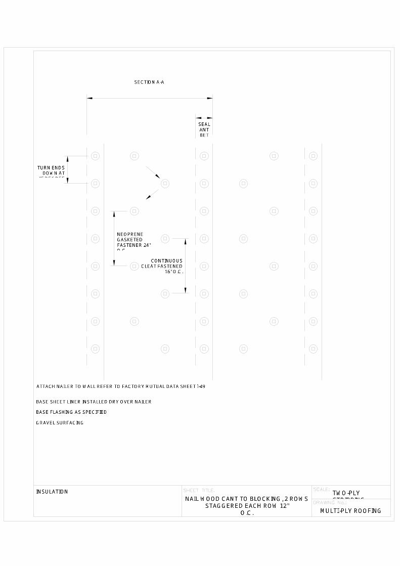


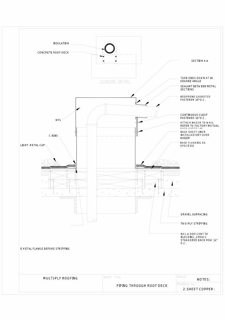


Addendum No. 1 – USD #500 2017 Main Library Roofing Project Page 1 of 3
ADDENDUM No. 1 Kansas City Kansas Public Schools (USD #500)
IFB 16-055 – 2017 Roofing Project for the Main Library December 19, 2016
You are instructed to read and note the following described changes, corrections, clarifications, omissions, deletions, additions, approvals and statements pertinent to the Construction Documents. Addendum No. 1 is a part of the Contract Bid and Construction Documents and shall govern in the performance of the Work. I. General Information A. Work can start on this project any time after receipt of contract and notice to
proceed. B. Submit the attached Revise Bid Form with the following changes: 1. Attachment A forms have been adjusted per contractor request. F. All materials listed on Attachment A forms shall ship prior to May 31, 2017 to
protect against price increase on June 1, 2017. G. Prime contractor shall use any subcontractor for their base and alternate bids as
long as their sub-contractors are licensed in the State of Kansas and Wyandotte County for the specific job requirements. 1. Contractor shall provide the district with a list of their sub-contractors
with their submittal package. 2. Any sub-contractor not meeting the state and county requirements shall
not be allowed on the project. H. If any electrical change orders are needed, the Prime Contractor shall use the
Districts electrical contractor under contract; which is currently RF Fisher. I. The Prime Contractor shall provide a sub-contractor to provide a water test on all
existing drains prior to starting the project. 1. Contractor shall water test all drains using a standard ¾” hose running full
on for a minimum of 10-minutes per drain. 2. Contractor shall verify that the primary roof drains, overflow roof drains,
and plumbing vents located within the project area are free of debris and properly functioning. The contractor shall perform a flood test of existing roof drain bowls and connections to piping by temporarily plugging the drain pipe below the existing connection and flooding the drain bowl to its top edge. Notify the Owner immediately if defects are found in the roof drain bowl and/or roof drain assembly components, or if the roof drains and/or plumbing vents are found to be blocked, clogged, or otherwise not properly functioning. Any plumbing work necessary to correct identified defects, and clear existing roof drains and vents shall be performed by a licensed plumber at the direction of the Owner. Prior to start of work, the contractor shall provide a letter to the Owner indicating this work has been completed, detailing the results of this roof drain inspection and testing, and identifying any corrective action needed.
3. After completion of roofing work, the Prime Contractor shall again obtain the services of a licensed plumbing contractor to verify that primary roof

Addendum No. 1 – USD #500 2017 Main Library Roofing Project Page 2 of 3
drains, overflow roof drains and plumbing vents located within the project area are free of debris and properly functioning. The plumber shall perform a second flood test of existing roof drains located in the project areas. The flood test shall include the same testing as completed prior to the roofing work. Continue to flood the roof drain, up and over the installed roof drain flashing. Notify the Prime Contractor and Owner immediately if defects are found in the roof drain flashing, roof drain bowl and/or roof drain assembly components, or if the roof drains and/or plumbing vents are found to be flocked, clogged, or otherwise not properly functioning. Plumbing work necessary to correct identified defects, and clear existing roof drains and vents shall be performed by a licensed plumber at the direction of the Owner and paid for by the Prime Contractor. After construction completion, the contractor shall provide a second letter to the Owner indicating this work has been completed, detailing the results of this roof drain inspection and testing, and identifying any corrective action needed.
J. All questions related to these projects shall be provided to the District no later than December 19, 2016 by 4:00 P.M.
K. The job site ground footprint to be secured by 8’ chain link fence, shall encompass; all material, equipment, tools, kettle, ORI’s, and anything related to these projects.
L. Contractors shall provide pull-out test over all gypsum or lightweight concrete decks. 1. Contractor shall provide the District results of their test and submit what
type and size of fasteners they will be using. II. Specification Adds, Deletions, or Changes:
A. Roof 1 1. Remove and replace existing aluminum coping over brick wall north of
cooling tower. a. Install a peel and stick membrane or trilaminate base sheet over
wall prior to installing new coping. 2. Extend base sheet over new perimeter wood blocking and seal on outside
fascia of wood. a. Wood blocking shall be secured and made 100% watertight with
new base sheet. 3. Delete the polyurethane anti-skid walkway and use TRA Walkways as
included on Revised Bid Form Attachment A form. 4. Alternate Price shall include the same roof membrane for Roof 1 as Roofs
2, 3, and 4 and the following: a. Mechanically fasten trilaminate base sheet over gypsum deck with
fasteners approved to meet FM 1-90 wind classification. b. Install adhered base sheet and 3-ply membrane and flashings as
specified for Roofs 2, 3 and 4. B. Roofs 1 and 3 1. At one mechanical unit sitting on wood sleepers on Roof 1 by the cooling
tower and two units on rails and sleepers on Roof 3, provide the following: a. Use a licensed mechanical sub-contractor to disconnect these units,
raise as needed, install new rails supports on the decks, install new flashing as specified, and 22-gauge pre-finished rail caps.

Addendum No. 1 – USD #500 2017 Main Library Roofing Project Page 3 of 3
b. New rails shall be a minimum of 8” above the new finished
membrane.
C. Roofs 2 and 4 1. Install a peel and stick membrane or trilaminate base sheet over the
outside parapet walls prior to installing new coping.
END OF ADDENDUM I

USD #500 December 2016 2017 Main Library Roofing Project
REVISED BID FORM 00411 - 1
DOCUMENT 00411 – REVISED BID FORM
USD #500 Bidder: ___________________________________ 2017 - Main Library Roof Replacement Project (Bidder enter name here) 625 Minnesota Ave. Kansas City, Kansas 66101
BASE BID OR ALTERNATE BID, SINGLE-PRIME (ALL TRADES) CONTRACT The undersigned Bidder, having carefully examined the Bidding and Contract Requirements, Conditions of the Contract, Drawings, Specifications, and all subsequent Addenda, all as issued by the Owner, having visited the site, and being familiar with all conditions and requirements of the Work, hereby agrees to furnish all material (other than roofing material listed on Attachment A), labor, equipment and services as described in the above documents, without exception, including all scheduled Allowances if any, necessary to complete the specified work. USD #500 shall purchase all roofing material supplied by the primary roofing material manufacturer for all projects. The Bidder shall provide Attachment A with their bid, verifying quantities required to complete this project as specified. All materials not listed on Attachment A shall be the responsibility of the Bidder. The cost for the items listed on Attachment A shall not be included in your Base Bid price. Failure to provide the mandatory Attachment A with verified quantities will render your bid non-responsive.
Single Prime (All trades) Contract for the above-named Project, in accordance with the requirements of the Bidding Documents, for the sum of:
BASE BID 1. Main Library – Single Ply Roof System $_____________________ ALTERNATE BID 1. Main Library – Built-Up Roof System $__________________ADD or DEDUCT
UNIT PRICES 1. Wood Blocking Replacement $_________________per board foot 2. Drain Bowl Replacement – 5” $_________________each 3. Drain Clamping Ring Replacement $_________________each 4. Metal Deck Repair $_________________per square foot 5. Metal Deck Replacement $_________________per square foot 6. Concrete Deck Repair $_________________per cubic foot 7. Gypsum Deck Repair $_________________per cubic foot 8. 18-gauge Metal – Flat-stock $_________________per square foot 9. Plywood Replacement 5/8” $_________________per square foot

USD #500 December 2016 2017 Main Library Roofing Project
REVISED BID FORM 00411 - 2
BONDING Bid shall be accompanied by an acceptable bid bond or certified cashier's check drawn on a local bank, payable to Treasurer, Board of Education, for an amount not less than five percent of the total amount of the bid. This bid security shall become the property of the Board of Education as liquidated damages in the event the successful bidder fails to execute and deliver a contract, along with specified surety and statutory bonds, within ten days after the received notice of the acceptance of his bid by the Board of Ed-ucation. The undersigned Bidder agrees to furnish a Payment & Performance Bond, in the amount of 100% of total contract value after receipt of contract.
TIME OF COMPLETION The undersigned Bidder proposes and agrees hereby to commence the Work of the Contract Documents on a date specified in a written Notice to Proceed to be issued by the District, and work shall be complet-ed within 120 days after receipt of Notice to Proceed. If work cannot be completed within specified timeframe, contractor shall provide immediate repairs to stop or minimize leaks until work is completed and shall pay as a late fee the sum of $800 for each consecutive calendar day that work is not completed thereafter.
ACKNOWLEDGEMENT OF ADDENDA The undersigned Bidder acknowledges receipt of and use of the following Addenda in the preparation of this Bid: Addendum No. 1, dated _____________ Addendum No. 2, dated _____________ Addendum No. 3, dated _____________ Addendum No. 4, dated _____________
CONTRACTOR'S LICENSE The undersigned further states that he is a duly licensed Contractor, for the type of work proposed, in the State of Kansas, and that all fees, permits, etc., pursuant to the submission of this proposal have been paid in full.

USD #500 December 2016 2017 Main Library Roofing Project
REVISED BID FORM 00411 - 3
SUBMISSION OF BID Respectfully submitted this ____ day of ____________, 2017.
By:
(Name of bidding firm or corporation)
Witness: By:
(Signature)
Attest:
(Signature) (Type or print name)
By: Title:
(Type or print name) (Owner/Partner/President/Vice Pres.)
Title: Address:
(Corporate Secretary or Assistant Secretary Only)
Phone:
License:
(Affix Corporate Seal Here) Federal ID No.:

USD #500 December 2016 2017 Main Library Roofing Project
REVISED BID FORM 00411 - 4
ATTACHMENT A USD #500
2017 - Main Library Roofing Project Base Bid #1
Products Material Size & Container Material Quantity AlphaGuard WB Primer 1 gallon bucket 2 – bucket AlphaGuard MT Base Coat 5 gallon bucket 9 – buckets AlphaGuard MT Top Coat 5 gallon bucket 6 – buckets AlphaGuard M-Prime 1 gallon buckets 1 – bucket Burmastic Adhesive 52 gallon lined barrels 16 - barrels Burmastic Composite Ply 20 rolls per pallet - 2/sq/roll 12 – pallets Burmastic 33-lb Glass Ply 20 rolls per pallet – 2/sq/roll 5 - pallets Burmastic SF Adhesive 5 gallon buckets 115 - buckets Burmesh 6” x 300’ rolls 3 - rolls Double Duty Aluminum 5 gallon bucket 9 – buckets ELS 5 gallon buckets 36 - buckets Low Rise Foam Adhesive 4 sets per case (1.5 gal/case) 18 - cases Permafab 40” x 324’ roll 1 – roll Permafab 12” x 300’ roll 1 - roll Polyroof SF 3 gallon bucket 63 - buckets TPA 80 mil. Fleeced Back 78” x 75” roll 39 - rolls TPA 45 mil Flashing 24” x 50’ roll 20 – rolls TPA/LV Bonding Adhesive 5 gallon buckets 9 - buckets TPA WB Bonding Adhesive 5 gallon buckets 38 - buckets TPA Small Flashing Boots 10 per case 1 - case TPA Universal Corners Inside & Outside 10 per case 4 - cases TPA T-Joint Patches 100 per case 2 - case TPA Cover Strip 6” x 100’ roll 6 - rolls TPA Walkway Roll 72 mil Gray 3’ x 60’ 2 - rolls TRA Elastomeric Sheeting 18” x 50’ roll 18 – rolls TremSeal D 30 tubes per case 1 - cases TremSeal Pitch Pan Sealer 4 cartridge sets/case – 1.5 gal/case 8 – cases Contractor Name: __________________________________________ Project Size: _________________________________square feet

USD #500 December 2016 2017 Main Library Roofing Project
REVISED BID FORM 00411 - 5
ATTACHMENT A USD #500
2017 – Main Library Roofing Project Alternate Bid #1
Products Material Size & Container Material Quantity AlphaGuard WB Primer 1 gallon bucket 2 – bucket AlphaGuard MT Base Coat 5 gallon bucket 9 – buckets AlphaGuard MT Top Coat 5 gallon bucket 6 – buckets AlphaGuard M-Prime 1 gallon bucket 1 - bucket Burmastic Adhesive 52 gallon lined barrels 60 - barrels Burmastic Composite Ply 20 rolls per pallet - 2/sq/roll 12 – pallets Burmastic 33-lb Glass Ply 20 rolls per pallet – 2/sq/roll 19 - pallets Burmastic SF Adhesive 5 gallon buckets 115 - buckets Burmesh 6” x 300’ rolls 7 - rolls Double Duty Aluminum 5 gallon bucket 12 – buckets ELS 5 gallon buckets 36 - buckets Low Rise Foam Adhesive 4 sets per case (1.5 gal/case) 18 - cases Permafab 40” x 324’ roll 1 – roll Permafab 12” x 300’ roll 1 - roll Polyroof SF 3 gallon bucket 145 - buckets TRA Elastomeric Sheeting 18” x 50’ roll 32 – rolls TremSeal D 30 tubes per case 1 - cases TremSeal Pitch Pan Sealer 4 cartridge sets/case – 1.5 gal/case 8 – cases Contractor Name: __________________________________________ Project Size: _________________________________square feet
END OF DOCUMENT 00411