Kactus2: Component editor€¦ · Kactus2: Component editor Requirements Kactus2 Software version...
18
Kactus2: Component editor Requirements Kactus2 Software version 2.0 (Build 1) or newer Table of Contents Requirements ...................................................................................................................................................... 1 HW component editor ........................................................................................................................................ 2 General editor.................................................................................................................................................. 2 File sets editor ................................................................................................................................................. 4 File set editor ................................................................................................................................................... 5 File editor ......................................................................................................................................................... 7 Model parameters editor (VHDL Generics) ................................................................................................... 8 Address space editor (CPUs)........................................................................................................................... 9 Views editor ..................................................................................................................................................... 9 Flat view editor (RTL) ....................................................................................................................................10 Ports editor ....................................................................................................................................................11 Bus interfaces editor .....................................................................................................................................13 Bus interface editor.......................................................................................................................................14 Port maps editor............................................................................................................................................15 CPUs editor ....................................................................................................................................................17
Transcript of Kactus2: Component editor€¦ · Kactus2: Component editor Requirements Kactus2 Software version...

Kactus2: Component editor
Requirements Kactus2 Software version 2.0 (Build 1) or newer
Table of Contents Requirements ...................................................................................................................................................... 1
HW component editor ........................................................................................................................................ 2
General editor.................................................................................................................................................. 2
File sets editor ................................................................................................................................................. 4
File set editor ................................................................................................................................................... 5
File editor ......................................................................................................................................................... 7
Model parameters editor (VHDL Generics) ................................................................................................... 8
Address space editor (CPUs)........................................................................................................................... 9
Views editor ..................................................................................................................................................... 9
Flat view editor (RTL) .................................................................................................................................... 10
Ports editor .................................................................................................................................................... 11
Bus interfaces editor ..................................................................................................................................... 13
Bus interface editor ....................................................................................................................................... 14
Port maps editor ............................................................................................................................................ 15
CPUs editor .................................................................................................................................................... 17

HW component editor Creating new HW component follows the same principles as creating a new bus. First select new fromthe top pane, under File group. From the pop-up window select HW Component from the left handmenu. Select IP from the Product Hierarchy pull down menu and correct Firmness pull down menu.
The Product pull down option lets you choose which type of component you are specifying. Firmnessoption gives information how the component can be modified. These are extensions to standard IP-XACT.
General editor

General editor contains the general information of a component, such as description.
On the top of the editor the VLNV-identifier and the file path to the xml-file are shown. These fieldscan’t be modified and if user wants to change the VLNV then the component must be saved as newcomponent with new VLNV. Kactus2 attributes contain the hierarchy, firmness and implementation ofwhich the implementation can’t be modified.
Attributes are a Kactus2-specific extension to the IP-XACT standard and their purpose is explainedbelow:
Attribute nameAttributevalue
Value description
Producthierarchy
Global Component does not fit into any other category.
Product Component represents a final product.
BoardComponent represents development- or final hardware platform i.e. a circuitboard.
Chip Component represents a chip i.e. some specific FPGA-chip.
SoC Component represents a system on chip.
IP Component represents a single IP-block.
Implementation
HW Component is hardware implementation.
SW Component is a software implementation.
SYSComponent contains information about the software component mapping to theunderlaying hardware platform.
Firmness
TemplateComponent is a model that can be used as a base when creating new componentsto the library but must not be used as such.
Mutable Component is fully modifiable.
ParametrizableComponent contains parameters that can be used to configure it but it can't bemodified further.
Fixed Component can’t be configured in any way and it is frozen to it's final state.
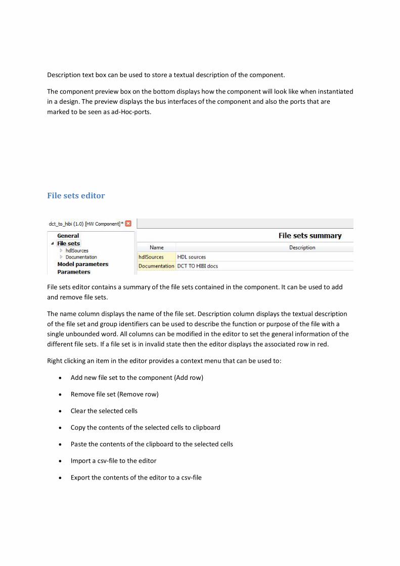
Description text box can be used to store a textual description of the component.
The component preview box on the bottom displays how the component will look like when instantiatedin a design. The preview displays the bus interfaces of the component and also the ports that aremarked to be seen as ad-Hoc-ports.
File sets editor
File sets editor contains a summary of the file sets contained in the component. It can be used to addand remove file sets.
The name column displays the name of the file set. Description column displays the textual descriptionof the file set and group identifiers can be used to describe the function or purpose of the file with asingle unbounded word. All columns can be modified in the editor to set the general information of thedifferent file sets. If a file set is in invalid state then the editor displays the associated row in red.
Right clicking an item in the editor provides a context menu that can be used to:
Add new file set to the component (Add row)
Remove file set (Remove row)
Clear the selected cells
Copy the contents of the selected cells to clipboard
Paste the contents of the clipboard to the selected cells
Import a csv-file to the editor
Export the contents of the editor to a csv-file

Group identifiers can contain several identifiers and the possible words are not limited. However theeditor suggests the following options for the group identifiers:
Diagnostics
Documentation
ProjectFiles
Simulation
sourceFiles
File set editor
File set editor can be used to edit the details of a single file set and to add and remove files contained inthe file set. File sets can be used to group files together to be referenced by other sections of acomponent.
On the top the name, display name and description of the file set are shown. Name is used to identifythe file set within a component and the description contains a textual description of the file set.
The files group box lists the files contained in the file set. File name contains the name of the file and filepath displays the relative file path from the component’s xml-file to the file. File types column displaysthe file types defined for the file and the description contains the textual description of a single file. Thefile types and description columns are editable but the file name and file path are not. The “Add Files”button opens a dialog that can be used to select files on the disk to add to the file set.
The files box also contains a context menu that has the following options:
Add new file to the file set (Add row)
Remove file from file set (Remove row)
Clear the selected cells
Copy the contents of the selected cells to clipboard
Paste the contents of the clipboard to the selected cells
Import a csv-file to the editor
Export the contents of the editor to a csv-file
If a file is in invalid state, i.e. missing a mandatory file type, then the file is displayed in red color. Theorder of files is maintained and can be changed by dragging rows. If the compilation order of files isimportant then the files should be listed in order needed by compilation.
The default build command can be used to define commands how to build files of the specified filetypes. The file type column displays a file type and the command and flags columns display the buildcommand and the flags set for the associated file type. The replace default flags column defines if theflags are appended to the current flags or shall replace the existing flags of a build command. The buildcommands editor contains a similar context menu as the files editor.
Group identifiers can contain several identifiers and the possible words are not limited. However theeditor suggests the following options for the group identifiers:
Diagnostics
Documentation
ProjectFiles
Simulation
sourceFiles
These identifiers can be used to describe the purpose of the file set.
Dependent directories can be used to describe a list of paths to directories containing files on which thefile set depends.

File editor
File editor can be used to edit the details of a single file within a file set.
The name field contains the relative file path from the containing component’s xml-file to the file. Thefile types list is used to specify the type of the file. File type can be used i.e. when specifying buildcommands for files.
The logical name of a file can be used i.e. to specify a VHDL library for a VHDL-file. If the "only used asdefault"-check box is checked then the logical name is only used as default and can be overridden byanother process.
The “is include file” and “contains external declarations” -check boxes can be used to specify the file isan include file and that the file contains external declarations and is needed by other files in this file set.
Description contains the textual description of the file and the build command can be used to define aspecific build command or –flags for this file. If the “replace default flags”-check box is checked then thedefault flags of the build script are replaced, if not then the flags are appended to the default flags.Target name is used to specify a path to the file that is derived from this file when build process is run.

Model parameters editor (VHDL Generics)
Model parameters editor can be used to add, remove and modify the model parameters of acomponent. Model parameters are often used in HDL languages to pass information to the model toconfigure it (e.g. VHDL generics).
Model parameters editor contains a context menu that has the following options:
Add new model parameter (Add row)
Remove model parameter (Remove row)
Clear the selected cells
Copy the contents of the selected cells to clipboard
Paste the contents of the clipboard to the selected cells
Import a csv-file to the editor
Export the contents of the editor to a csv-file
All columns of the editor are editable.
The name column contains the name of the model parameter. Data type specifies the data type of themodel parameter as it pertains to the language of the model. For example in VHDL this could bestd_logic or integer and in case of C-language int or char*. The usage type specifies how this modelparameter is used. Typed parameters appear in object-oriented languages, i.e. in C++. Non-typedparameters are found in all languages, i.e. in VHDL all types are non-typed.
Value contains the actual value of the model parameter. The value can be overridden by assigningconfigurable element value for this model parameter within a design that instantiates this component.Description contains the textual description of the associated model parameter.

Address space editor (CPUs)
Address spaces editor contains the summary of the address spaces of the component. This editor can beused to add and remove address spaces to the containing component. Editor enables user also to setthe general information of an address space.
Name column contains the name of the address space and the description column a textual descriptionof the address space. Addressable unit size specifies the number of bits each address incrementcontains. Width is the bit width of a row in the address space. Range is the address range of an addressspace expressed as addressable units.
Address spaces editor contains a context menu providing following options:
Add new address space (Add row)
Remove address space (Remove row)
Clear the selected cells
Copy the contents of the selected cells to clipboard
Paste the contents of the clipboard to the selected cells
Import a csv-file to the editor
Export the contents of the editor to a csv-file
Views editor

Views editor provides a summary of the views of the component. The editor can be used to add andremove views.
The name and description columns are editable and contain the name and textual description of thecorresponding view. The view type is not editable and is used to inform the user if the view ishierarchical or not. Hierarchical views contain a reference to a design or configuration which instantiatesub-components. Non-hierarchical views reference the file sets within the containing component.
The editor contains a context menu that contains following options:
Add new view (Add row)
Remove view (Remove row)
Clear the selected cells
Copy the contents of the selected cells to clipboard
Paste the contents of the clipboard to the selected cells
Import a csv-file to the editor
Export the contents of the editor to a csv-file
Views that are currently in an invalid state are displayed in red.
Flat view editor (RTL)

Flat view editor is used to edit the non-hierarchical views of a component. User may change the type ofthe view thus changing the editor type between this editor and the hierarchical view editor.
The name and description fields are used to edit the name and textual description of the view.Environment identifiers specify information about the tool environment of the view. The view type isused to select between flat view editor and hierarchical view editor. These fields mentioned arecommon with flat editor and hierarchical editor. The rest of the fields are specific for non-hierarchicalviews.
Language specifies the HDL for the view, i.e. this may be vhdl or verilog. Model name is a language-specific and therefore depends on the implementation language of the field. For VHDL this may be aconfiguration name or the entity(architecture) name.
File set references contain a list of file set names within the containing component that this view uses.Default file build commands contains a list of build commands and flags for the files contained in the filesets referenced through the file sets.
Ports editor
Ports editor provides a table containing all the ports of a component. This editor is used to add, removeand edit the ports.
Port name identifies each port and must match the name of the port in the implementation language.For example in case of VHDL the ports listed in the entity declaration are to be listed here.
The direction columns specifies the direction of the port and has four options:
in for input ports.
out for output ports.
inout for bidirectional and tri-state ports.
phantom for ports that exist on the IP-Xact component but not on the implementation.

The left and right bound define the width of the port in case of vectored ports. The width of the port isleft bound – right bound + 1. In case of scalar ports the left bound = right bound.
The port type specifies the type of the port. In case of VHDL the typical values for scalar and vectoredports are std_logic and std_logic_vector. The type definition is a language specific reference to wherethe type is defined. In previous example the type defition is IEEE.std_logic_1164.all. In case of SystemCthe type definition is the include file name, i.e. systemc.h.
The default value is used to assign a default value for an unconnected port. For example this is usedwhen generating a structural vhdl for the top-level hierarchical component to assign values to inputports that are not connected to any other port in the design. The description contains a textualdescription of the port.
The ad-Hoc column is a Kactus2-specific extension which is used in the graphical user interface of ahierarchical design.
The component instances are drawn as rectangles and their external interfaces are drawn to the edgesof the rectangle. In this case the instance has 5 bus interfaces: clk, led, rst_n, from_hibi and pkt_codec.Normally this is all that user sees of the interfaces of a component but if user selects ports to be shownas ad-Hoc then those ports are shown also. Figure above displays two ad-Hoc ports: rx_av_in andled_out, the directions of the ports can also be seen by the port icon.
Ports editor provides a context menu that contains following options:
Add new port (Add row)
Remove port (Remove row)
Clear the selected cells
Copy the contents of the selected cells to clipboard
Paste the contents of the clipboard to the selected cells
Import a csv-file to the editor
Export the contents of the editor to a csv-file

Bus interfaces editor
The bus interfaces editor displays a summary of the bus interfaces of a component. Bus interface is usedto group ports together to form an interface that i.e. fulfills requirements for a bus protocol. This editoris used to add and remove bus interfaces in a component.
The name and description columns contain the name and textual description of the bus interface. Theinterface column is used to select the interface mode of a bus interface.
There are seven different interface modes:
Master - indicates that the interface is the one that initiates transactions.
Slave - is the one that responds to transactions.
System - can be used for some interfaces that do not fit into the master or slave category.
Mirrored slave - is the mirrored version of slave interface and may provide address offsets to theconnected slave interfaces.
Mirrored master - is the mirrored version of master interface.
Mirrored system - is the mirrored version of system interface.
Monitor - is an interface that can be used for verification process. This interface type gathers data fromother interfaces.
The idea of mirrored interfaces is that they have the same ports as the normal interfaces but thedirections of the ports are inverted.
The bus definition and abstraction definition columns are not editable and they display the VLNV-identifiers of the IP-Xact documents that define qualities of the hardware bus that the interface fulfills.These fields can be set in the bus interface-specific editor.

Bus interface editor
Bus interfaces editor is used to edit the details of a single bus interface. Bus interface is used to groupports together to form an interface that i.e. fulfills requirements for a bus protocol. The editor containstwo tabs: the general tab which is used to set the general settings of the interface and the port maps tabwhich is used to group ports to the interface.
The name and description contain the name and textual description of the bus interface. Bus definitionand abstraction definition contain VLNV-references to the bus definition and abstraction definition IP-Xact documents that are associated with this interface. Those documents define the qualities that thisbus interface must meet. For example the abstraction definition defines the logical signals that belong tothe bus. These logical signals are used to define how the physical ports of the component are connectedin the bus, this is explained in the help page of port maps editor.
Interface mode combo box selects the interface mode of the bus interface. Below the combo box arethe interface mode-specific fields that are used to edit options of the currently selected interface mode.
In the general group the addressable unit size defines how many bits are included in the leastaddressable unit of the bus. The default setting is byte addressable (8 bits). The endianness indicateswhether the interface is big-endian or little-endian. The bit steering can be set to on or off. The bitsteering on implies that the interface is able to align data on different byte channels in case ofaddressable interfaces. The default setting when the bit steering is not set is off. When checked theconnection required indicates that when instantiated in a design, this interface must be connected tosome other interface and can’t be left unconnected.

Port maps editor
The port maps tab of a bus interface editor is used to group the physical ports of the containingcomponent to the logical signals listed in the associated abstraction definition.
The top-left corner contains a list of the logical signals that were defined in the abstraction definitionassigned in the general tab. The top-right corner contains a list of the physical ports in the component.The bottom table displays the mappings between logical signals and physical ports. A mapping can becreated by dragging an item from one of the top lists to the another or by selecting an item in the bothlists and pressing enter or clicking the connect button. After this the selected items disappear from thetop lists and appear as mapped on the port map table on the bottom.
If user selects several items on both lists and connects them, then mappings between the ports aremade in the order which the items were listed. If a mapping from one port to many is desired then usermay toggle the “1 to many” button and select a single item on either list and connect it to all selectedports on the other list. User can remove the mappings from the bottom table by selecting the row andpressing delete or selecting “Remove mapping” from the context menu. When a mapping is removedthe associated ports return to the top lists. Pressing the clean up-button will remove any duplicate portsfrom the lists. A port can also be returned to the top list by selecting it in the bottom table and selecting“Restore port to list” in the context menu. Picture below depicts how the physical ports between twocomponent instances are connected through their bus interfaces.

On the left side is a list of physical ports found on the component A. The right side lists the physical portsfound on a component B. The lines between the physical ports and the logical signals represent thecreated port mappings in the bus interfaces. For example component A has mapped its port comm_outto the logical signal COMM. Because the component B has mapped its port comm_in to the same logicalsignal this means that the ports are connected together if user connects these interfaces together in adesign. Of course if no connection is made between the component instances in the design then noports are connected. All ports of the component do not need to be mapped in the interface nor do allthe logical signals of the abstraction definition need to be associated with a physical port. Abstractiondefinition defines the directions of the signals in different interface modes thus making it possible tovalidate connections so that two output ports are not accidentally connected to each other. In the figureabove the abstraction definition could have defined the DATA signal to have direction out in masterinterfaces and in at slave interfaces.
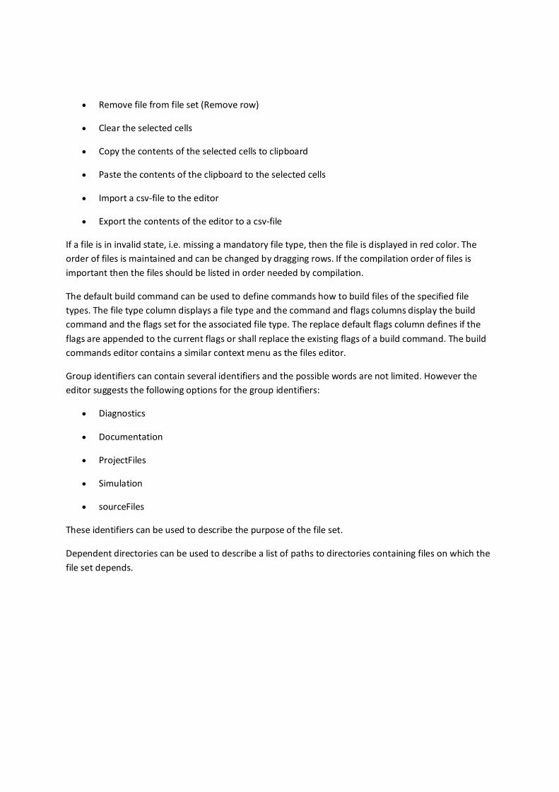
A vectored physical port can be sliced to connect only part of it by assigning left and right bounds in themapping table. Picture below depicts how a part of the physical port can be connected.
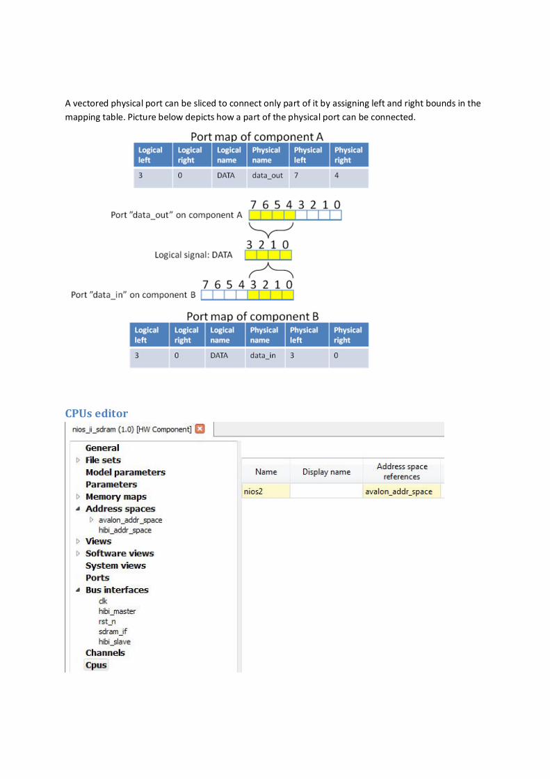
CPUs editor

The CPUs editor displays the programmable cores the component contains.
The name and description contain the name and textual description of the programmable core. Addressspace references contain the names of the address spaces that specify the logical address space of theCPU. The master interfaces of a component may reference the same address spaces to create a linkbetween programmable core and interface.
CPUs editor provides a context menu with the following options:
Add new cpu (Add row)
Remove cpu (Remove row)
Clear the selected cells
Copy the contents of the selected cells to clipboard
Paste the contents of the clipboard to the selected cells
Import a csv-file to the editor
Export the contents of the editor to a csv-file