
K8 Operation and Parts Manual - SternTHE BEATLES SERVICE AND OPERATION MANUAL Games configured for...
50
THE BEATLES SERVICE AND OPERATION MANUAL Games configured for North America operate on 60 cycle electricity only. These games will not operate in countries with 50 cycle electricity (Europe, UK, Australia). WARNING IMPORTANT HEALTH WARNING: PHOTOSENSITIVE SEIZURES - A very small percentage of people may experience a seizure when exposed to certain visual images, in- cluding flashing lights or patterns. Even people with no history of seizures of epilepsy may have an undiagnosed condition that can cause “photosensitive epileptic seizures” due to certain visual images, flashing lights or patterns. Symptoms can include lightheadedness, altered vision, eye or face twitching, jerking or shaking of arms or legs, disorientation, confusion, momentary loss of awareness, and loss of consciousness or convulsions that can lead to injury from falling down or striking nearby objects. IMMEDIATELY STOP PLAYING AND CONSULT A DOCTOR IF YOU EXPERIENCE ANY OF THESE SYMPTOMS. 1-800-KICKERS - [email protected] www.sternpinball.com - facebook.com/sternpinball MANUAL #780-50K8-00 THE BEATLES GOLD #500-55K8-01 THE BEATLES PLATINUM #500-55K7-01 THE BEATLES DIAMOND #500-55K9-01 © 2018 Apple Corps Ltd. All rights reserved. A Beatles™ product lecensed by Apple Corps Ltd. “Beatles” is a trademark of Apple Corps Ltd. “Apple” and the Apple logo are exclusively licensed by Apple Corps Ltd. Stern Pinball machines are assembled in Elk Grove Village, Illinois, USA. Stern Pinball has inspected each game element to ensure it meets our quality standards. Each pinball machine has unique characteristics that make it a one-of-a-kind American made product. Each will have variations in appearance resulting from differences in the machine’s particular wood parts, individual printed art and mechanical assemblies. No playfield is perfectly flat and varies depending on the season. Game play will result in playfield dimpling as the harder steel ball contacts the wood and coating; over time multiple dimples will blend to make them less noticeable. Normal plastic insert crazing (tiny stress cracks) and ghosting (small cloudy areas around insert edges) are often seen in pinball machines, due to a combination of plastic mold stress, pushing of inserts into purposely undersized holes, and heating and breaking of inserts’ plastic “skin” when the playfield is sanded. SERVICE AND OPERATION MANUAL ATTENTION! IMPORTANT WARRANTY INFORMATION The electronics system, node network architecture, mechanical devices and associated software control systems in this pinball machine are designed to work with genuine Stern Pinball accessories and devices. Installation of non-authorized accessories, lamps, LED’s, motors or other devices or modification of electro-mechanical devices may damage the system and will void your warranty.
Transcript of K8 Operation and Parts Manual - SternTHE BEATLES SERVICE AND OPERATION MANUAL Games configured for...

THE BEATLES SERVICE AND OPERATION MANUAL
Games configured for North America operate on 60 cycle electricity only. These games will not operate in countries with 50 cycle electricity (Europe, UK, Australia).
WARNING IMPORTANT HEALTH WARNING: PHOTOSENSITIVE SEIZURES - A very small percentage of people may experience a seizure when exposed to certain visual images, in-cluding flashing lights or patterns. Even people with no history of seizures of epilepsy may have an undiagnosed condition that can cause “photosensitive epileptic seizures” due to certain visual images, flashing lights or patterns. Symptoms can include lightheadedness, altered vision, eye or face twitching, jerking or shaking of arms or legs, disorientation, confusion, momentary loss of awareness, and loss of consciousness or convulsions that can lead to injury from falling down or striking nearby objects.
IMMEDIATELY STOP PLAYING AND CONSULT A DOCTOR IF YOU EXPERIENCE ANY OF THESE SYMPTOMS.
1-800-KICKERS - [email protected] www.sternpinball.com - facebook.com/sternpinball
MANUAL #780-50K8-00 THE BEATLES GOLD #500-55K8-01
THE BEATLES PLATINUM #500-55K7-01 THE BEATLES DIAMOND #500-55K9-01
© 2018 Apple Corps Ltd. All rights reserved.A Beatles™ product lecensed by Apple Corps Ltd.“Beatles” is a trademark of Apple Corps Ltd. “Apple” and the Apple logo are exclusively licensed by Apple Corps Ltd.
Stern Pinball machines are assembled in Elk Grove Village, Illinois, USA. Stern Pinball has inspected each game element to ensure it meets our quality standards.
Each pinball machine has unique characteristics that make it a one-of-a-kind American made product. Each will have variations in appearance resulting from differences in the machine’s particular wood parts, individual printed art and mechanical assemblies. No playfield is perfectly flat and varies depending on the season. Game play will result in playfield dimpling as the harder steel ball contacts the wood and coating; over time multiple dimples will blend to make them less noticeable. Normal plastic insert crazing (tiny stress cracks) and ghosting (small cloudy areas around insert edges) are often seen in pinball machines, due to a combination of plastic mold stress, pushing of inserts into purposely undersized holes, and heating and breaking of inserts’ plastic “skin” when the playfield is sanded.
SERVICE AND OPERATION MANUAL
ATTENTION! IMPORTANT WARRANTY INFORMATION
The electronics system, node network architecture, mechanical devices and associated software control systems in this pinball machine are designed to work with genuine Stern Pinball accessories and devices.
Installation of non-authorized accessories, lamps, LED’s, motors or other devices or modification of electro-mechanical devices may damage the system and will void your warranty.
2
THE BEATLES MANUAL 500-55K8-01© 2018 Apple Corps Ltd. All rights reserved. A Beatles™ product lecensed by Apple Corps Ltd. “Beatles” is a trademark of Apple Corps Ltd. “Apple” and the Apple logo are exclusively licensed by Apple Corps Ltd.
TABLE OF CONTENTS1. Setup and Moving .................................. 3
1.1 First-Time Setup Instructions ............................... 31.2 Adjustments Menu ............................................... 61.3 Transporting the Game ........................................ 71.4 Maintenance ........................................................ 81.5 Maintenance Kits ................................................. 81.6 Common Parts ..................................................... 8
2. SPIKE System and Node Guide ............ 92.1 SPIKE System Overview ...................................... 92.2 Node Bus Cabling ................................................ 92.3 System Power ...................................................... 92.4 SPIKE Node Addresses ....................................... 92.5 SPIKE Node Programming................................. 102.6 SPIKE System Terminology ............................... 102.7 Common SPIKE Node Boards ........................... 10
3. Light, Switch, and Driver Reference ... 113.1 SPIKE Node Boards ........................................... 113.2 Driver Reference ................................................ 123.3 Switch Reference ............................................... 143.4 Light Reference .................................................. 183.5 Motor Reference ................................................ 22
4. Electronic Pinouts and Schematics.... 234.1 SPIKE-2 CPU Node 0 ........................................ 234.2 Cabinet Node 1 .................................................. 274.3 Lower Playfield 48V Driver Pinout Node 8 ......... 284.4 Mid Upper Playfield 48V Driver Pinout Node 9 .. 294.5 Trough Serial Opto Receiver Extension 8a ........ 304.6 Trough Serial Opto Transmitter .......................... 304.7 Lower Center LED Board 8b .............................. 304.8 Drop Target 2 LED Board 8c .............................. 314.9 Drop Target 1 LED Board 8d .............................. 314.10 Main Center LED Board 9a ................................ 324.11 Dual Motor Driver ............................................... 32
4.12 Right LED Board ................................................ 334.13 Half Curve LED Board - Left .............................. 334.14 Half Curve LED Board - Right ............................ 334.15 Main Power Supply ............................................ 334.16 Power Distribution Board ................................... 344.17 Power Plug Wiring.............................................. 34
5. Parts Reference .................................... 355.1 Playfield Rubber Parts ....................................... 355.2 Rubber Size Chart .............................................. 355.3 Playfield Assemblies, Top .................................. 365.4 Playfield Assemblies, Bottom ............................ 375.5 Backbox Parts.................................................... 385.6 Speaker Panel Parts .......................................... 385.7 Cabinet Parts ..................................................... 395.8 Ball Shooter Assembly ....................................... 405.9 Auto Launch Assembly ...................................... 405.10 Ball Trough Assembly......................................... 415.11 Slingshot Assembly............................................ 415.12 Flipper Assembly, Left ........................................ 425.13 Flipper Assembly, Right ..................................... 425.14 Pop Bumper Assembly ...................................... 435.15 Right Upper Flipper Assembly w/ Cut Foot ....... 445.16 Magnetic Spinning Disc Assembly .................... 445.17 3-Bank Drop Target Assembly ........................... 455.18 4-Bank Drop Target Assembly ........................... 455.19 Left Spinner Assembly ....................................... 465.20 Right Spinner Assembly ..................................... 465.21 Single Opto & Bracket Assembly ....................... 475.22 Double Opto & Bracket Assembly ..................... 475.23 Back Panel Assembly ........................................ 47
6. Specifications ....................................... 486.1 Game Dimensions .............................................. 486.2 Warranty ............................................................. 496.3 Warnings, Compliance, and Legal Notices ........ 49
"A Hard Day's Night" Performed by The Beatles Courtesy of Calderstone Productions Ltd. / Apple Corps Ltd. under license from Universal Music Enterprises
"All My Loving" Performed by The Beatles Courtesy of Calderstone Productions Ltd. / Apple Corps Ltd. under license from Universal Music Enterprises
"Can't Buy Me Love" Performed by The Beatles Courtesy of Calderstone Productions Ltd. / Apple Corps Ltd. under license from Universal Music Enterprises
"Drive My Car" Courtesy of Calderstone Productions Ltd. / Apple Corps Ltd. under license from Universal Music Enterprises
"Help" Courtesy of Calderstone Productions Ltd. / Apple Corps Ltd. under license from Universal Music Enterprises
"I Should Have Known Better" Courtesy of Calderstone Productions Ltd. / Apple Corps Ltd. under license from Universal Music Enterprises
"It Won't Be Long" Courtesy of Calderstone Productions Ltd. / Apple Corps Ltd. under license from Universal Music Enterprises
“Taxman” Courtesy of Calderstone Productions Ltd. / Apple Corps Ltd. under license from Universal Music Enterprises
“Ticket To Ride” Courtesy of Calderstone Productions Ltd. / Apple Corps Ltd. under license from Universal Music Enterprises
“A Hard Day’s Night” by John Lennon, Paul McCartney / Composition owned by Sony/ATV Tunes LLC (ASCAP)
“All My Loving” by John Lennon, Paul McCartney / Composition owned by Sony/ATV Tunes LLC (ASCAP)
“Can’t Buy Me Love” by John Lennon, Paul McCartney / Composition owned by Sony/ATV Tunes LLC (ASCAP)
“Drive My Car” by John Lennon, Paul McCartney / Composition owned by Sony/ATV Tunes LLC (ASCAP)
“Help” by John Lennon, Paul McCartney / Composition owned by Sony/ATV Tunes LLC (ASCAP)
“I Should Have Known Better” by John Lennon, Paul McCartney / Composition owned by Sony/ATV Tunes LLC (ASCAP)
“It Won’t Be Long” by John Lennon, Paul McCartney / Composition owned by Sony/ATV Tunes LLC (ASCAP)
“Taxman” by George Harrison / Composition owned by Sony/ATV Tunes LLC (ASCAP)
“Ticket To Ride” by John Lennon, Paul McCartney / Composition owned by Sony/ATV Tunes LLC (ASCAP)
Special thanks: Gretsch Guitars, Ludwig, Pan American World Airways, Rickenbacker, and Vox. Copyright © 2018 Ludwig Drums. All Rights Reserved © 2018 Rickenbacker International Corporation © RIC, logotypes © 2018 Gretsch Guitars. All rights reserved. Copyright © Pan American World Airways Copyright © 2018 VOX AMPLIFICATION LTD. All Rights Reserved
1. SETUP AND MOVING
225 5 7
7
1
9
8
11
15
11
8
6
14
14
SETUP AND MOVING
3THE BEATLES MANUAL 500-55K8-01© 2018 Apple Corps Ltd. All rights reserved. A Beatles™ product lecensed by Apple Corps Ltd. “Beatles” is a trademark of Apple Corps Ltd. “Apple” and the Apple logo are exclusively licensed by Apple Corps Ltd.
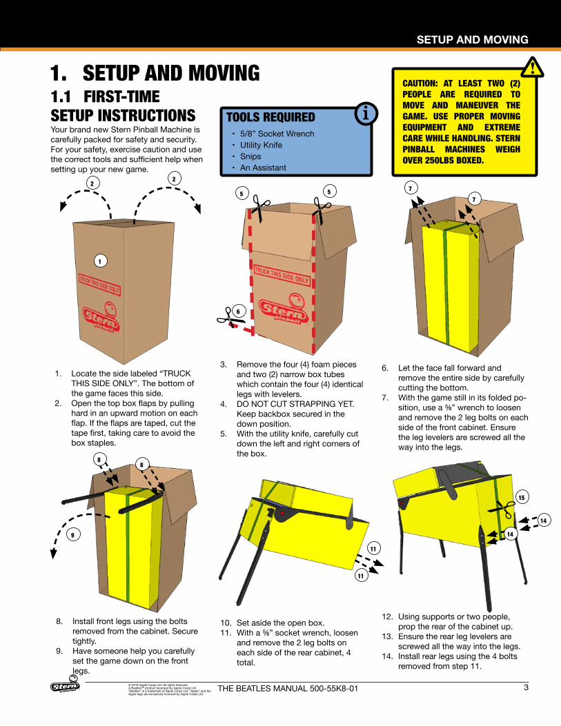
1.1 FIRST-TIME SETUP INSTRUCTIONS
CAUTION: AT LEAST TWO (2) PEOPLE ARE REQUIRED TO MOVE AND MANEUVER THE GAME. USE PROPER MOVING EQUIPMENT AND EXTREME CARE WHILE HANDLING. STERN PINBALL MACHINES WEIGH OVER 250LBS BOXED.
TOOLS REQUIRED• 5/8” Socket Wrench• Utility Knife• Snips• An Assistant
Your brand new Stern Pinball Machine is carefully packed for safety and security. For your safety, exercise caution and use the correct tools and sufficient help when setting up your new game.
1. Locate the side labeled “TRUCK THIS SIDE ONLY”. The bottom of the game faces this side.
2. Open the top box flaps by pulling hard in an upward motion on each flap. If the flaps are taped, cut the tape first, taking care to avoid the box staples.
3. Remove the four (4) foam pieces and two (2) narrow box tubes which contain the four (4) identical legs with levelers.
4. DO NOT CUT STRAPPING YET. Keep backbox secured in the down position.
5. With the utility knife, carefully cut down the left and right corners of the box.
6. Let the face fall forward and remove the entire side by carefully cutting the bottom.
7. With the game still in its folded po-sition, use a ⅝” wrench to loosen and remove the 2 leg bolts on each side of the front cabinet. Ensure the leg levelers are screwed all the way into the legs.
8. Install front legs using the bolts removed from the cabinet. Secure tightly.
9. Have someone help you carefully set the game down on the front legs.
10. Set aside the open box.11. With a ⅝” socket wrench, loosen
and remove the 2 leg bolts on each side of the rear cabinet, 4 total.
12. Using supports or two people, prop the rear of the cabinet up.
13. Ensure the rear leg levelers are screwed all the way into the legs.
14. Install rear legs using the 4 bolts removed from step 11.
19
21
17
25
2627
FIRST-TIME SETUP CONTINUED
27
4
SETUP AND MOVING
THE BEATLES MANUAL 500-55K8-01© 2018 Apple Corps Ltd. All rights reserved. A Beatles™ product lecensed by Apple Corps Ltd. “Beatles” is a trademark of Apple Corps Ltd. “Apple” and the Apple logo are exclusively licensed by Apple Corps Ltd.
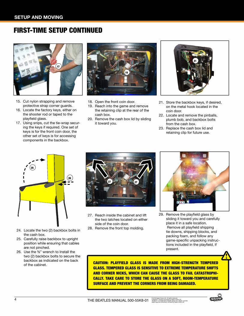
15. Cut nylon strapping and remove protective strap corner guards.
16. Locate the factory keys, either on the shooter rod or taped to the playfield glass.
17. Using snips, cut the tie-wrap secur-ing the keys if required. One set of keys is for the front coin door, the other set of keys is for accessing components in the backbox.
18. Open the front coin door.19. Reach into the game and remove
the retaining clip at the rear of the cash box.
20. Remove the cash box lid by sliding it toward you.
21. Store the backbox keys, if desired, on the metal hook located in the coin door.
22. Locate and remove the pinballs, plumb bob, and backbox bolts from the cash box.
23. Replace the cash box lid and retaining clip for future use.
24. Locate the two (2) backbox bolts in the cash box.
25. Carefully raise backbox to upright position while ensuring that cables are not pinched.
26. Use the ⅝” wrench to Install the two (2) backbox bolts to secure the backbox as indicated on the back of the cabinet.
27. Reach inside the cabinet and lift the two latches located on either side of the coin door.
28. Remove the front top molding.
29. Remove the playfield glass by sliding it toward you and carefully place it in a safe location. Remove all playfield shipping tie downs, shipping blocks, and packing foam, and follow any game-specific unpacking instruc-tions included in the playfield, if present.
CAUTION: PLAYFIELD GLASS IS MADE FROM HIGH-STRENGTH TEMPERED GLASS. TEMPERED GLASS IS SENSITIVE TO EXTREME TEMPERATURE SHIFTS AND CORNER NICKS, WHICH CAN CAUSE THE GLASS TO FAIL CATASTROPHI-CALLY. TAKE CARE TO STORE THE GLASS ON A SOFT, ROOM-TEMPERATURE SURFACE AND PREVENT THE CORNERS FROM BEING DAMAGED.
SETUP AND MOVING
5THE BEATLES MANUAL 500-55K8-01© 2018 Apple Corps Ltd. All rights reserved. A Beatles™ product lecensed by Apple Corps Ltd. “Beatles” is a trademark of Apple Corps Ltd. “Apple” and the Apple logo are exclusively licensed by Apple Corps Ltd.
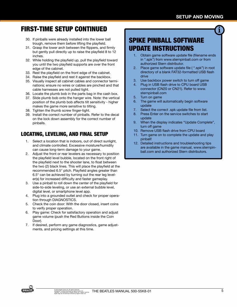
30. If pinballs were already installed into the lower ball trough, remove them before lifting the playfield.
31. Grasp the lower arch between the flippers, and firmly but gently pull directly up to raise the playfield 8 to 12 inches.
32. While holding the playfield up, pull the playfield toward you until the two playfield supports are over the front edge of the cabinet.
33. Rest the playfield on the front edge of the cabinet.34. Raise the playfield and rest it against the backbox.35. Visually inspect all cabinet cables and connector termi-
nations; ensure no wires or cables are pinched and that cable harnesses are not pulled tight.
36. Locate the plumb bob in the parts bag in the cash box.37. Slide plumb bob onto the hanger wire. Note: the vertical
position of the plumb bob affects tilt sensitivity - higher makes the game more sensitive to tilting.
38. Tighten the thumb screw finger-tight.39. Install the correct number of pinballs. Refer to the decal
on the lock down assembly for the correct number of pinballs.
LOCATING, LEVELING, AND FINAL SETUP1. Select a location that is indoors, out of direct sunlight,
and climate controlled. Excessive moisture/humidity can cause long-term damage to your game.
2. Adjust the front or rear levelers as necessary to position the playfield level bubble, located on the front right of the playfield next to the shooter lane, to float between the two (2) black lines. This will place the playfield at the recommended 6.5° pitch. Playfield angles greater than 6.5° can be achieved by turning out the rear leg level-er(s) for increased difficulty and faster gameplay.
3. Use a pinball to roll down the center of the playfield for side-to-side leveling, or use an external bubble level, digital level, or smartphone level app.
4. Plug into a grounded outlet and check for proper opera-tion through DIAGNOSTICS.
5. Check the coin door: With the door closed, insert coins to verify proper operation.
6. Play game: Check for satisfactory operation and adjust game volume (push the Red Buttons inside the Coin Door).
7. If desired, perform any game diagnostics, game adjust-ments, and pricing settings at this time.
FIRST-TIME SETUP CONTINUEDSPIKE PINBALL SOFTWARE UPDATE INSTRUCTIONS
1. Obtain game software update file (filename ends in “.spk”) from www.sternpinball.com or from authorized Stern distributor.
2. Place game software update file ( “.spk”) in root directory of a blank FAT32-formatted USB flash drive
3. Use backbox power switch to turn off game4. Plug in USB flash drive to CPU board USB
connector (CN20 or CN21). Refer to www.sternpinball.com
5. Turn on game6. The game will automatically begin software
update7. Select the correct .spk update file from list.8. Press Enter on the service switches to start
update9. When the display indicates “Update Complete”,
turn off game10. Remove USB flash drive from CPU board11. Turn game on to complete the update and play
pinball!12. Detailed instructions and troubleshooting tips
are available in the game manual, www.sternpin-ball.com and authorized Stern distributors.
6
SETUP AND MOVING
THE BEATLES MANUAL 500-55K8-01© 2018 Apple Corps Ltd. All rights reserved. A Beatles™ product lecensed by Apple Corps Ltd. “Beatles” is a trademark of Apple Corps Ltd. “Apple” and the Apple logo are exclusively licensed by Apple Corps Ltd.
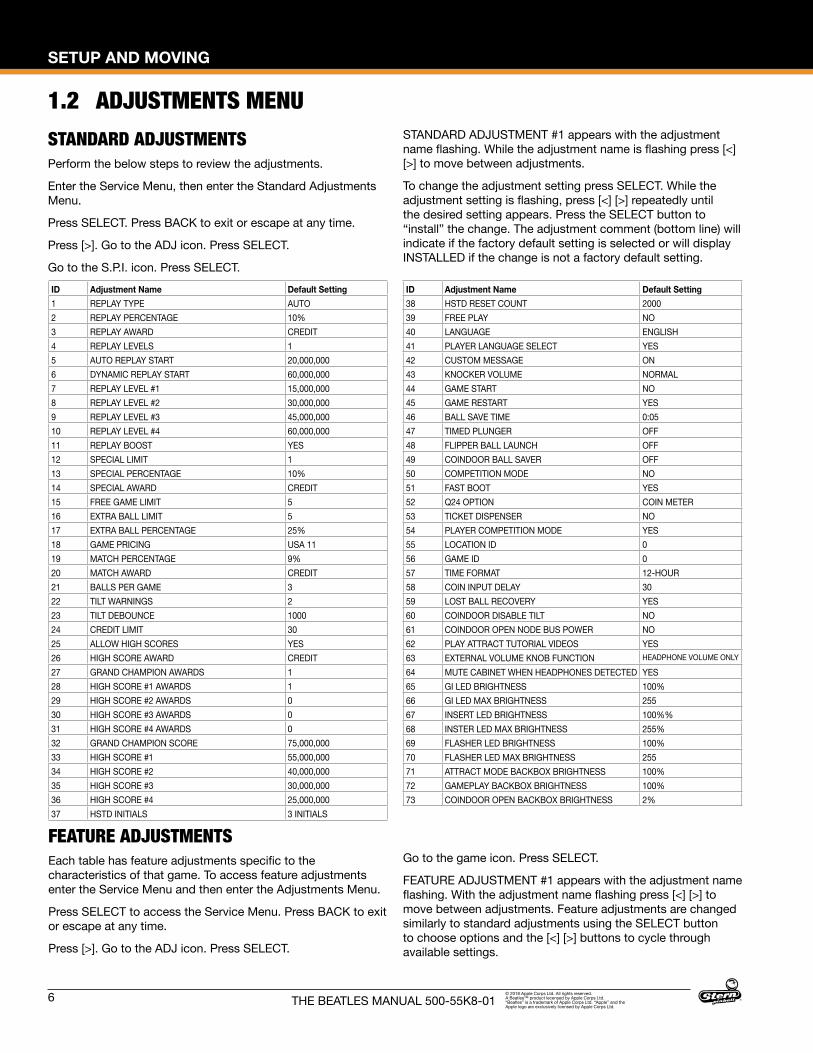
1.2 ADJUSTMENTS MENUSTANDARD ADJUSTMENTSPerform the below steps to review the adjustments.
Enter the Service Menu, then enter the Standard Adjustments Menu.
Press SELECT. Press BACK to exit or escape at any time.
Press [>]. Go to the ADJ icon. Press SELECT.
Go to the S.P.I. icon. Press SELECT.
STANDARD ADJUSTMENT #1 appears with the adjustment name flashing. While the adjustment name is flashing press [<] [>] to move between adjustments.
To change the adjustment setting press SELECT. While the adjustment setting is flashing, press [<] [>] repeatedly until the desired setting appears. Press the SELECT button to “install” the change. The adjustment comment (bottom line) will indicate if the factory default setting is selected or will display INSTALLED if the change is not a factory default setting.
FEATURE ADJUSTMENTSEach table has feature adjustments specific to the characteristics of that game. To access feature adjustments enter the Service Menu and then enter the Adjustments Menu.
Press SELECT to access the Service Menu. Press BACK to exit or escape at any time.
Press [>]. Go to the ADJ icon. Press SELECT.
Go to the game icon. Press SELECT.
FEATURE ADJUSTMENT #1 appears with the adjustment name flashing. With the adjustment name flashing press [<] [>] to move between adjustments. Feature adjustments are changed similarly to standard adjustments using the SELECT button to choose options and the [<] [>] buttons to cycle through available settings.
ID Adjustment Name Default Setting1 REPLAY TYPE AUTO2 REPLAY PERCENTAGE 10%3 REPLAY AWARD CREDIT4 REPLAY LEVELS 15 AUTO REPLAY START 20,000,0006 DYNAMIC REPLAY START 60,000,0007 REPLAY LEVEL #1 15,000,0008 REPLAY LEVEL #2 30,000,0009 REPLAY LEVEL #3 45,000,00010 REPLAY LEVEL #4 60,000,00011 REPLAY BOOST YES12 SPECIAL LIMIT 113 SPECIAL PERCENTAGE 10%14 SPECIAL AWARD CREDIT15 FREE GAME LIMIT 516 EXTRA BALL LIMIT 517 EXTRA BALL PERCENTAGE 25%18 GAME PRICING USA 1119 MATCH PERCENTAGE 9%20 MATCH AWARD CREDIT21 BALLS PER GAME 322 TILT WARNINGS 223 TILT DEBOUNCE 100024 CREDIT LIMIT 3025 ALLOW HIGH SCORES YES26 HIGH SCORE AWARD CREDIT27 GRAND CHAMPION AWARDS 128 HIGH SCORE #1 AWARDS 129 HIGH SCORE #2 AWARDS 030 HIGH SCORE #3 AWARDS 031 HIGH SCORE #4 AWARDS 032 GRAND CHAMPION SCORE 75,000,00033 HIGH SCORE #1 55,000,00034 HIGH SCORE #2 40,000,00035 HIGH SCORE #3 30,000,00036 HIGH SCORE #4 25,000,00037 HSTD INITIALS 3 INITIALS
ID Adjustment Name Default Setting38 HSTD RESET COUNT 200039 FREE PLAY NO40 LANGUAGE ENGLISH41 PLAYER LANGUAGE SELECT YES42 CUSTOM MESSAGE ON43 KNOCKER VOLUME NORMAL44 GAME START NO45 GAME RESTART YES46 BALL SAVE TIME 0:0547 TIMED PLUNGER OFF48 FLIPPER BALL LAUNCH OFF49 COINDOOR BALL SAVER OFF50 COMPETITION MODE NO51 FAST BOOT YES52 Q24 OPTION COIN METER53 TICKET DISPENSER NO54 PLAYER COMPETITION MODE YES55 LOCATION ID 056 GAME ID 057 TIME FORMAT 12-HOUR58 COIN INPUT DELAY 3059 LOST BALL RECOVERY YES60 COINDOOR DISABLE TILT NO61 COINDOOR OPEN NODE BUS POWER NO62 PLAY ATTRACT TUTORIAL VIDEOS YES63 EXTERNAL VOLUME KNOB FUNCTION HEADPHONE VOLUME ONLY
64 MUTE CABINET WHEN HEADPHONES DETECTED YES65 GI LED BRIGHTNESS 100%66 GI LED MAX BRIGHTNESS 25567 INSERT LED BRIGHTNESS 100%%68 INSTER LED MAX BRIGHTNESS 255%69 FLASHER LED BRIGHTNESS 100%70 FLASHER LED MAX BRIGHTNESS 25571 ATTRACT MODE BACKBOX BRIGHTNESS 100%72 GAMEPLAY BACKBOX BRIGHTNESS 100%73 COINDOOR OPEN BACKBOX BRIGHTNESS 2%
SETUP AND MOVING
7THE BEATLES MANUAL 500-55K8-01© 2018 Apple Corps Ltd. All rights reserved. A Beatles™ product lecensed by Apple Corps Ltd. “Beatles” is a trademark of Apple Corps Ltd. “Apple” and the Apple logo are exclusively licensed by Apple Corps Ltd.
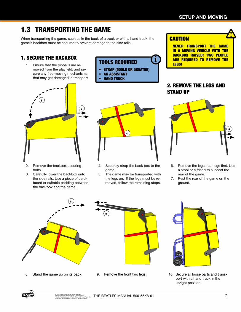
1. SECURE THE BACKBOX1. Ensure that the pinballs are re-
moved from the playfield, and se-cure any free-moving mechanisms that may get damaged in transport
2. Remove the backbox securing bolts
3. Carefully lower the backbox onto the side rails. Use a piece of card-board or suitable padding between the backbox and the game.
4. Securely strap the back box to the game
5. The game may be transported with the legs on. If the legs must be re-moved, follow the remaining steps.
2. REMOVE THE LEGS AND STAND UP
1.3 TRANSPORTING THE GAME
2
3
4
6. Remove the legs, rear legs first. Use a stool or a friend to support the rear of the game.
7. Rest the rear of the game on the ground.
6
CAUTIONNEVER TRANSPORT THE GAME IN A MOVING VEHICLE WITH THE BACKBOX RAISED! TWO PEOPLE ARE REQUIRED TO REMOVE THE LEGS!
10. Secure all loose parts and trans-port with a hand truck in the upright position.
8. Stand the game up on its back.
8
9. Remove the front two legs.
9
When transporting the game, such as in the back of a truck or with a hand truck, the game’s backbox must be secured to prevent damage to the side rails.
TOOLS REQUIRED• STRAP (500LB OR GREATER)• AN ASSISTANT• HAND TRUCK
8
SETUP AND MOVING
THE BEATLES MANUAL 500-55K8-01© 2018 Apple Corps Ltd. All rights reserved. A Beatles™ product lecensed by Apple Corps Ltd. “Beatles” is a trademark of Apple Corps Ltd. “Apple” and the Apple logo are exclusively licensed by Apple Corps Ltd.
1.4 MAINTENANCEREGULAR MAINTENANCE - (MONTHLY/500 GAMES)
• Remove the playfield glass• Enter the software diagnostics menu, start lamp test, then
clean and wax the playfield. • While cleaning the playfield, identify and repair malfunction-
ing lights, loose parts, cracked plastics and worn rubber parts.
• While in diagnostics, enter the switch test (Select the "SW" Icon, then "TEST" Icon).
• Use a pinball to actuate all switches and verify the correct switch registers with the switch test.
• The game will play a sound to confirm the switch. • Lift the playfield and inspect all assemblies for loose parts,
broken wires or excessive wear. Look at the bottom of the cabinet for any parts that may have worked loose, then find the source.
• Check all coin door mechanisms and bill acceptor (if in-stalled) for proper operation
• Play the game to ensure all coils and features are working• Check the playfield to ensure it is level and set to the prop-
er pitch using the bubble level on the right side wood rail.• Check game audits: Replay % and Ball Time and note
abnormal values which can indicate problems.• Ensure game volume is set appropriately for the location.• Clean both sides of the playfield glass and reinstall.• Check and clean pinballs and replace if excessively worn or
scuffed. Dirty pinballs accelerate game wear.
OVERHAUL MAINTENANCE - (5000 GAMES)• Verify latest game software is installed• Check flippers for excessive wear. Excessive flipper sloppi-
ness (vertical or horizontal) or weakness indicates a flipper rebuild is required.
• Clean machine inside and out and check leg levelers for free operation.
• Visual check for loose or broken playfield and cabinet parts and repair as necessary.
• Electrical check: Plug into grounded outlet and check for proper operation through DIAGNOSTICS.
• Replace worn or dirty rubbers.• Replace pinballs.• Check all playfield switches with a pinball.• Check all settings (refer to manual for factory settings).• Check coin door: With door closed, insert coins to verify
proper operation.• Check for proper adjustment of the plumb bob tilt.• Play game: Check for satisfactory operation.
COMMON PINBALL TOOLS• Common nut drivers (¼”, 5/16”, 11/32", ⅜”)• Phillips screwdriver• Standard Allen wrench/Hex key set• ⅝” Socket with ratchet• Adjustable wrench (5/8" & 9/16")• 6" Torpedo Level (or use a pinball • Flashlight or headlamp• Soldering Iron (60w with flat tip), lead-free solder • Wire cutter• Wire stripper• Long nose (“needle nose”) pliers
1.5 MAINTENANCE KITSDescription Part NumberThe Beatles Maintenance Kit8 oz pinball playfield wax (Novus # 2) (675-0003-01)Standard Pinball (260-5000-00)Cleaning ClothAll Playfield Rubber RingsSpare Fuses
502-6002-K8
The Beatles Deluxe Maintenance KitAll standard kit items, plus:Flipper rebuild kits, Left and Right (500-6307-10,-00)
502-6003-K8
The Beatles Playfield Plastics Kit 803-5000-K8The Beatles Playfield Decals Kit 802-5000-K8 [All]The Beatles Backbox Decal Left 820-78K8-01 [Gold]
820-78K7-01 [Platinum] 820-78K9-01 [Diamond]
The Beatles Backbox Decal Right 820-78K8-02 [Gold] 820-78K7-02 [Platinum] 820-78K9-02 [Diamond]
The Beatles Cabinet Decal Left 820-78K8-03 [Gold] 820-78K7-03 [Platinum] 820-78K9-03 [Diamond]
The Beatles Cabinet Decal Right 820-78K8-04 [Gold] 820-78K7-04 [Platinum] 820-78K9-04 [Diamond]
The Beatles Cabinet Decal Front 820-78K8-05 [Gold] 820-78K7-05 [Platinum] 820-78K9-05 [Diamond]
The Beatles Playfield, Bare 830-5100-K8The Beatles Gold Translite 830-8427-K8The Beatles Platinum Translite 830-8427-K7The Beatles Diamond Mirror Backglass 830-8426-K9
1.6 COMMON PARTSDescription Part Number8 oz Pinball Playfield wax (Novus # 2) 675-0003-01 Standard Pinball, 1-1/16 in 260-5000-00Flipper Rebuild Kit Left (Standard) 500-6307-10Flipper Base Plate Kit Left 515-6617-01Flipper Rebuild Kit Right 500-6307-00Flipper Base Plate Kit Right 515-6617-00
SPIKE SYSTEM AND NODE GUIDE
9THE BEATLES MANUAL 500-55K8-01© 2018 Apple Corps Ltd. All rights reserved. A Beatles™ product lecensed by Apple Corps Ltd. “Beatles” is a trademark of Apple Corps Ltd. “Apple” and the Apple logo are exclusively licensed by Apple Corps Ltd.
2. SPIKE SYSTEM AND NODE GUIDE2.1 SPIKE SYSTEM OVERVIEWThe SPIKE Pinball system is a rugged, distributed, and em-bedded platform custom-designed for the rigors of the pinball machine environment. SPIKE takes advantage of modern tech-nologies to deliver an immersive pinball experience that supports modern features, reduces cabling, and increases serviceability and reliability.
A Stern Pinball machine based on the SPIKE system will have at least two nodes networked together with the SPIKE node bus, a custom industrial pinball control bus that is designed around industry standards and optimized for the pinball environment. The primary CPU node is networked to one or more input/output nodes over standard Category 5 UTP (unshielded twisted pair) ethernet cabling.
There are five primary types of nodes that are found in the game.
• CPU node (Node 0) - The primary node that controls other nodes in the system. Contains the primary game software for the system and provides SPIKE node bus power for other nodes.
• Cabinet 48V node (Node 1) - Specialized node with specific inputs and outputs for coin doors, tilt mechanisms, and other bottom-cabinet devices.
• 48V playfield node - Controls high power devices such as coils and flashers, and also supports a few switch and low-power outputs. Powered by the system 48V power sup-ply.
• Light and switch node - High-density switch and low-power LED outputs, bus-powered from the node bus. These boards contain as many 32 switch inputs and light outputs.
• Node extensions - These sub-nodes add additional low-pow-er input and outputs to a specific Power or I/O node and are connected with simple serial bus.
2.2 NODE BUS CABLINGThe SPIKE node bus utilizes standard Ethernet-style RJ45 8-pin modular jacks, and off-the-shelf Category 5e or better ethernet cabling. The node bus is electrically different from Ethernet and does not utilize Ethernet or TCP/IP protocols or signaling stan-dards. SPIKE nodes are not compatible with standard computer networking equipment.
CAUTION: Plugging a SPIKE Node or CPU board into a standard Ethernet port may damage one or both devices and void your warranty.
2.3 SYSTEM POWERThe SPIKE System is powered from an 48V DC power supply bus. Each SPIKE node converts this voltage to lower voltages required by the node and its specific components. A SPIKE 48V node typically controls high-power outputs such as game coil mechanisms and high-brightness LEDs. These powered nodes are supplied directly with 48V system power. SPIKE standard I/O nodes are low-power nodes that read switch inputs and output to standard-brightness LEDs. Standard I/O nodes use the node bus power, which is supplied by the main CPU node over the node bus modular jack connectors.
2.4 SPIKE NODE ADDRESSESEach SPIKE node has a unique address ranging from 0 to 15. Not all addresses are used in all games. Nodes can be of the same part number, so the address is specified on the DIP switches on each node. When replacing a node, be certain that the correct address is set. Nodes can have 3-position and 4-position DIP switches. Refer to the appropriate table to set the address for each type of Node. The correct address for a node can be found in the SPIKE node reference section of the manual or in the game diagnostic software. Address 0 is reserved for the backbox CPU node, where the game software resides. Address 1 is reserved for the cabinet node, located inside the coin door. These two nodes do not have DIP switches as their address is not configurable.
Address 1 2 38 OFF OFF OFF9 OFF OFF ON10 OFF ON OFF11 OFF ON ON12 ON OFF OFF13 ON OFF ON14 ON ON OFF15 ON ON ON
SPIKE node addresses for nodes with 3-position DIP switches. Addresses 0-7 are not used by SPIKE nodes with 3-position DIP switches.
Address 1 2 3 48 OFF OFF OFF OFF9 OFF OFF ON OFF10 OFF ON OFF OFF11 OFF ON ON OFF12 ON OFF OFF OFF13 ON OFF ON OFF14 ON ON OFF OFF15 ON ON ON OFF
SPIKE node addresses for nodes with 4-position DIP switches. Addresses 0-7 are reserved for fixed-function nodes and do not require configuration.
10
SPIKE SYSTEM AND NODE GUIDE
THE BEATLES MANUAL 500-55K8-01© 2018 Apple Corps Ltd. All rights reserved. A Beatles™ product lecensed by Apple Corps Ltd. “Beatles” is a trademark of Apple Corps Ltd. “Apple” and the Apple logo are exclusively licensed by Apple Corps Ltd.
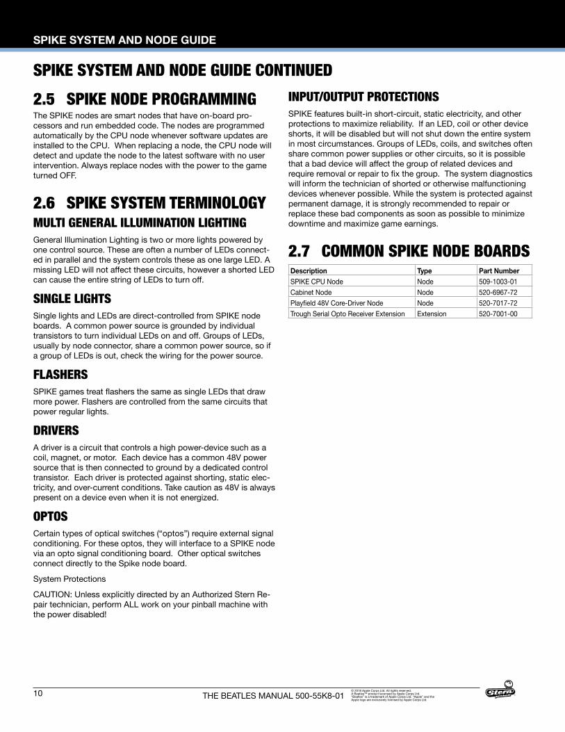
SPIKE SYSTEM AND NODE GUIDE CONTINUED2.5 SPIKE NODE PROGRAMMINGThe SPIKE nodes are smart nodes that have on-board pro-cessors and run embedded code. The nodes are programmed automatically by the CPU node whenever software updates are installed to the CPU. When replacing a node, the CPU node will detect and update the node to the latest software with no user intervention. Always replace nodes with the power to the game turned OFF.
2.6 SPIKE SYSTEM TERMINOLOGYMULTI GENERAL ILLUMINATION LIGHTINGGeneral Illumination Lighting is two or more lights powered by one control source. These are often a number of LEDs connect-ed in parallel and the system controls these as one large LED. A missing LED will not affect these circuits, however a shorted LED can cause the entire string of LEDs to turn off.
SINGLE LIGHTSSingle lights and LEDs are direct-controlled from SPIKE node boards. A common power source is grounded by individual transistors to turn individual LEDs on and off. Groups of LEDs, usually by node connector, share a common power source, so if a group of LEDs is out, check the wiring for the power source.
FLASHERSSPIKE games treat flashers the same as single LEDs that draw more power. Flashers are controlled from the same circuits that power regular lights.
DRIVERSA driver is a circuit that controls a high power-device such as a coil, magnet, or motor. Each device has a common 48V power source that is then connected to ground by a dedicated control transistor. Each driver is protected against shorting, static elec-tricity, and over-current conditions. Take caution as 48V is always present on a device even when it is not energized.
OPTOSCertain types of optical switches (“optos”) require external signal conditioning. For these optos, they will interface to a SPIKE node via an opto signal conditioning board. Other optical switches connect directly to the Spike node board.
System Protections
CAUTION: Unless explicitly directed by an Authorized Stern Re-pair technician, perform ALL work on your pinball machine with the power disabled!
INPUT/OUTPUT PROTECTIONSSPIKE features built-in short-circuit, static electricity, and other protections to maximize reliability. If an LED, coil or other device shorts, it will be disabled but will not shut down the entire system in most circumstances. Groups of LEDs, coils, and switches often share common power supplies or other circuits, so it is possible that a bad device will affect the group of related devices and require removal or repair to fix the group. The system diagnostics will inform the technician of shorted or otherwise malfunctioning devices whenever possible. While the system is protected against permanent damage, it is strongly recommended to repair or replace these bad components as soon as possible to minimize downtime and maximize game earnings.
2.7 COMMON SPIKE NODE BOARDSDescription Type Part NumberSPIKE CPU Node Node 509-1003-01Cabinet Node Node 520-6967-72Playfield 48V Core-Driver Node Node 520-7017-72Trough Serial Opto Receiver Extension Extension 520-7001-00

LIGHT, SWITCH, AND DRIVER REFERENCE
11THE BEATLES MANUAL 500-55K8-01© 2018 Apple Corps Ltd. All rights reserved. A Beatles™ product lecensed by Apple Corps Ltd. “Beatles” is a trademark of Apple Corps Ltd. “Apple” and the Apple logo are exclusively licensed by Apple Corps Ltd.
3. LIGHT, SWITCH, AND DRIVER REFERENCE
3.1 SPIKE NODE BOARDS
BACKBOX
CPU NODE 0
CABINET
CABINET NODE 1
CN11
CN13
CN22
CN4
CN5CN4
© 2018 Apple Corps Ltd. A Beatles™ product.
CN2CN1
CN2
CN3
CN1
CN2
CN1
CN1
CN2
CN3
755-7512-K8
When replacing node boards,ensure DIP address switchesare set correctly! PLAYFIELD REAR
PLAYFIELD FRONT
Node Bus Cable (RJ45)604-5004-08-XX
Serial Data Cable036-8054-XX
NODE BOARD ID INSTRUCTION SHEET
NODE 0
NODE 8aNODE 8
NODE 9a
NODE 8b
NODE 8d
NODE 9NODE 8c
ID DIP Address Description Location Part NumberNode 0 n/a SPIKE 2 CPU Node Backbox 509-1003-01Node 1 n/a Cabinet Node Cabinet 520-6967-72Node 8 OFF-OFF-OFF-OFF Playfield 48V Core-Driver Node Lower Playfield 520-7017-728a n/a Trough Serial Opto Receiver Extension Playfield 520-7001-008b n/a Lower Center LED Board Playfield 520-8067-008c n/a Drop Target 2 LED Board Playfield 520-8064-008d n/a Drop Target 1 LED Board Playfield 520-8063-00Node 9 OFF-OFF-ON-OFF Playfield 48V Core-Driver Node Playfield 520-7017-729a n/a Main Center LED Board Playfield 520-8066-00
ID DIP Address Description Location Part NumberNode 0 n/a SPIKE 2 CPU Node Backbox 509-1003-01Node 1 n/a Cabinet Node Cabinet 520-6967-72Node 8 OFF-OFF-OFF-OFF Playfield 48V Core-Driver Node Lower Playfield 520-7017-728a n/a Trough Serial Opto Receiver Extension Playfield 520-7001-008b n/a Lower Center LED Board Playfield 520-8067-008c n/a Drop Target 2 LED Board Playfield 520-8064-008d n/a Drop Target 1 LED Board Playfield 520-8063-00Node 9 OFF-OFF-ON-OFF Playfield 48V Core-Driver Node Playfield 520-7017-729a n/a Main Center LED Board Playfield 520-8066-00
12
SPIKE SYSTEM AND NODE GUIDE
THE BEATLES MANUAL 500-55K8-01© 2018 Apple Corps Ltd. All rights reserved. A Beatles™ product lecensed by Apple Corps Ltd. “Beatles” is a trademark of Apple Corps Ltd. “Apple” and the Apple logo are exclusively licensed by Apple Corps Ltd.
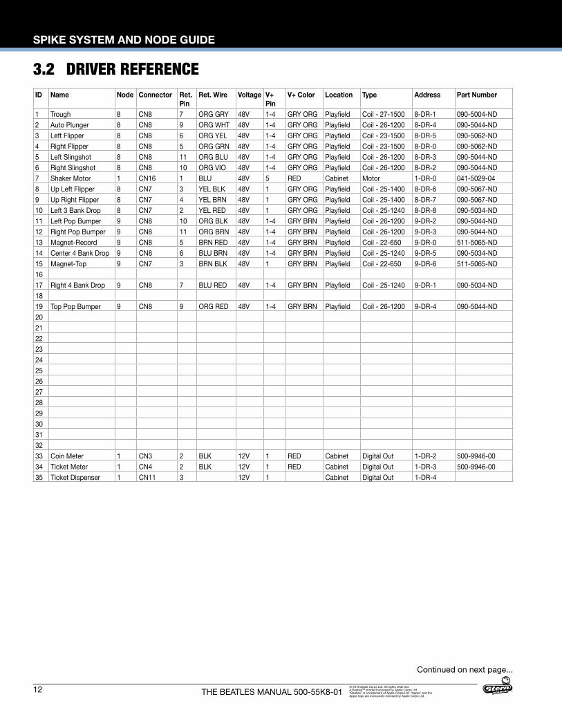
3.2 DRIVER REFERENCE
Continued on next page...
ID Name Node Connector Ret. Pin
Ret. Wire Voltage V+ Pin
V+ Color Location Type Address Part Number
1 Trough 8 CN8 7 ORG GRY 48V 1-4 GRY ORG Playfield Coil - 27-1500 8-DR-1 090-5004-ND2 Auto Plunger 8 CN8 9 ORG WHT 48V 1-4 GRY ORG Playfield Coil - 26-1200 8-DR-4 090-5044-ND3 Left Flipper 8 CN8 6 ORG YEL 48V 1-4 GRY ORG Playfield Coil - 23-1500 8-DR-5 090-5062-ND4 Right Flipper 8 CN8 5 ORG GRN 48V 1-4 GRY ORG Playfield Coil - 23-1500 8-DR-0 090-5062-ND5 Left Slingshot 8 CN8 11 ORG BLU 48V 1-4 GRY ORG Playfield Coil - 26-1200 8-DR-3 090-5044-ND6 Right Slingshot 8 CN8 10 ORG VIO 48V 1-4 GRY ORG Playfield Coil - 26-1200 8-DR-2 090-5044-ND7 Shaker Motor 1 CN16 1 BLU 48V 5 RED Cabinet Motor 1-DR-0 041-5029-048 Up Left Flipper 8 CN7 3 YEL BLK 48V 1 GRY ORG Playfield Coil - 25-1400 8-DR-6 090-5067-ND9 Up Right Flipper 8 CN7 4 YEL BRN 48V 1 GRY ORG Playfield Coil - 25-1400 8-DR-7 090-5067-ND10 Left 3 Bank Drop 8 CN7 2 YEL RED 48V 1 GRY ORG Playfield Coil - 25-1240 8-DR-8 090-5034-ND11 Left Pop Bumper 9 CN8 10 ORG BLK 48V 1-4 GRY BRN Playfield Coil - 26-1200 9-DR-2 090-5044-ND12 Right Pop Bumper 9 CN8 11 ORG BRN 48V 1-4 GRY BRN Playfield Coil - 26-1200 9-DR-3 090-5044-ND13 Magnet-Record 9 CN8 5 BRN RED 48V 1-4 GRY BRN Playfield Coil - 22-650 9-DR-0 511-5065-ND14 Center 4 Bank Drop 9 CN8 6 BLU BRN 48V 1-4 GRY BRN Playfield Coil - 25-1240 9-DR-5 090-5034-ND15 Magnet-Top 9 CN7 3 BRN BLK 48V 1 GRY BRN Playfield Coil - 22-650 9-DR-6 511-5065-ND1617 Right 4 Bank Drop 9 CN8 7 BLU RED 48V 1-4 GRY BRN Playfield Coil - 25-1240 9-DR-1 090-5034-ND1819 Top Pop Bumper 9 CN8 9 ORG RED 48V 1-4 GRY BRN Playfield Coil - 26-1200 9-DR-4 090-5044-ND2021222324252627282930313233 Coin Meter 1 CN3 2 BLK 12V 1 RED Cabinet Digital Out 1-DR-2 500-9946-0034 Ticket Meter 1 CN4 2 BLK 12V 1 RED Cabinet Digital Out 1-DR-3 500-9946-0035 Ticket Dispenser 1 CN11 3 12V 1 Cabinet Digital Out 1-DR-4
SPIKE SYSTEM AND NODE GUIDE
13THE BEATLES MANUAL 500-55K8-01© 2018 Apple Corps Ltd. All rights reserved. A Beatles™ product lecensed by Apple Corps Ltd. “Beatles” is a trademark of Apple Corps Ltd. “Apple” and the Apple logo are exclusively licensed by Apple Corps Ltd.
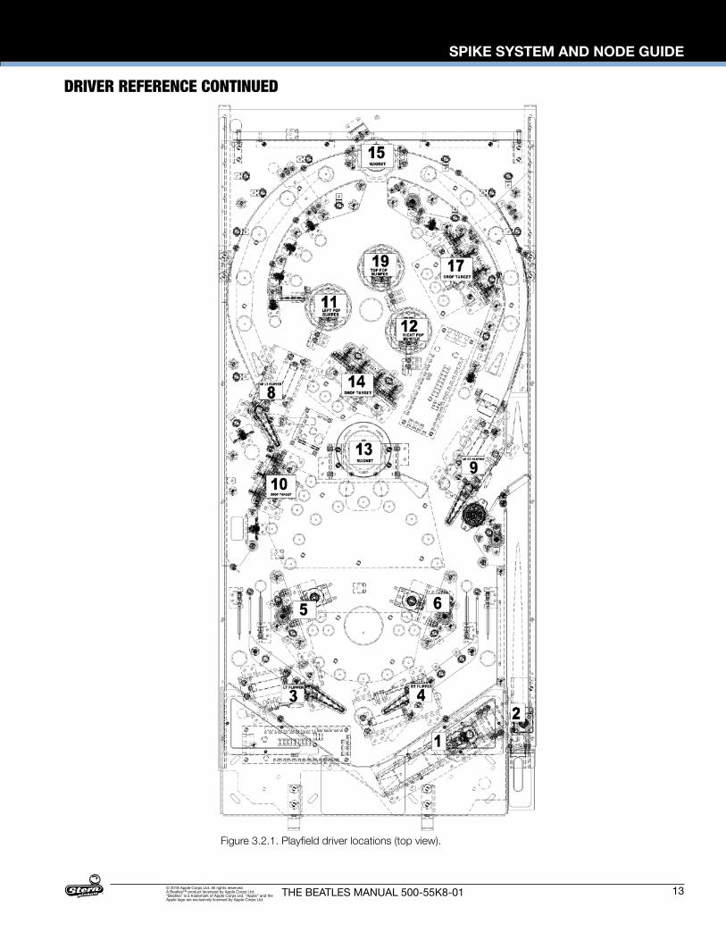
Figure 3.2.1. Playfield driver locations (top view).
DRIVER REFERENCE CONTINUED
14
SPIKE SYSTEM AND NODE GUIDE
THE BEATLES MANUAL 500-55K8-01© 2018 Apple Corps Ltd. All rights reserved. A Beatles™ product lecensed by Apple Corps Ltd. “Beatles” is a trademark of Apple Corps Ltd. “Apple” and the Apple logo are exclusively licensed by Apple Corps Ltd.
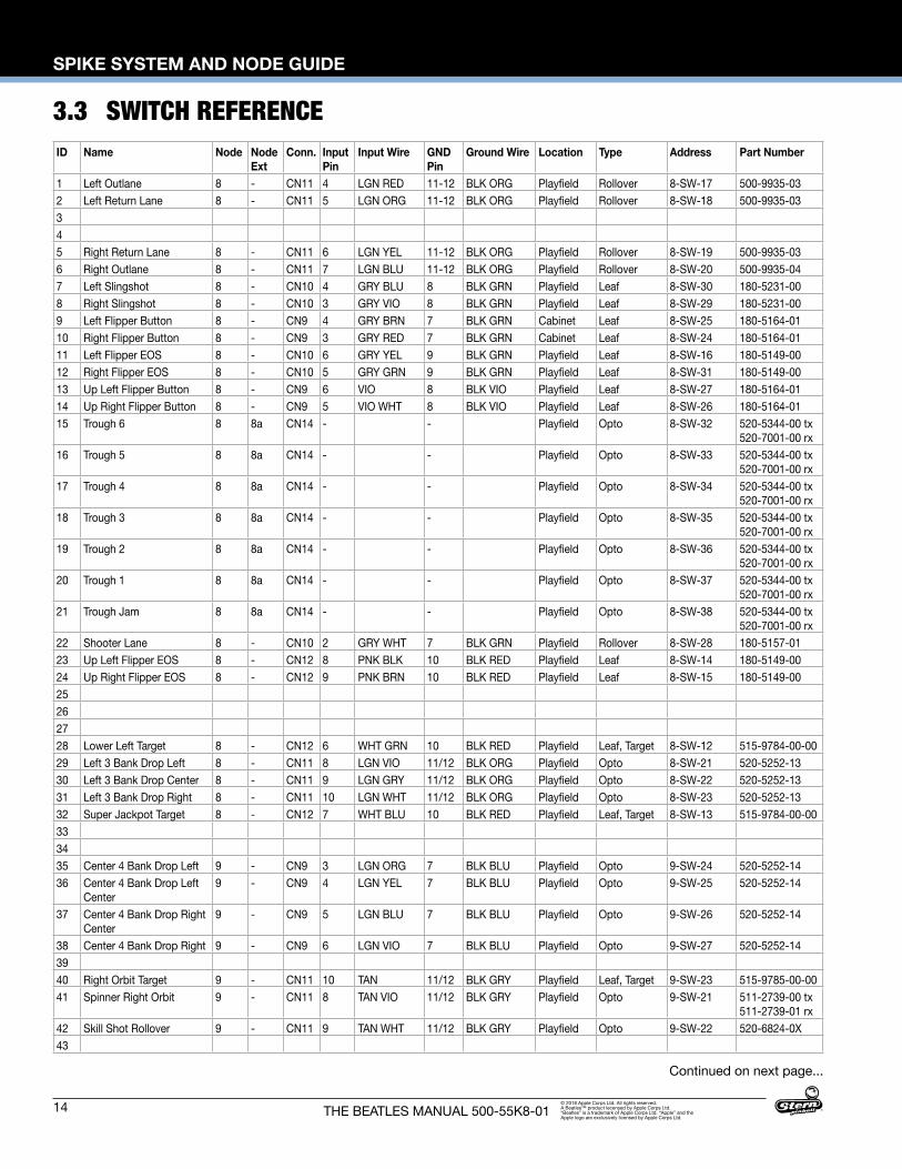
3.3 SWITCH REFERENCE
Continued on next page...
ID Name Node Node Ext
Conn. Input Pin
Input Wire GND Pin
Ground Wire Location Type Address Part Number
1 Left Outlane 8 - CN11 4 LGN RED 11-12 BLK ORG Playfield Rollover 8-SW-17 500-9935-032 Left Return Lane 8 - CN11 5 LGN ORG 11-12 BLK ORG Playfield Rollover 8-SW-18 500-9935-03345 Right Return Lane 8 - CN11 6 LGN YEL 11-12 BLK ORG Playfield Rollover 8-SW-19 500-9935-036 Right Outlane 8 - CN11 7 LGN BLU 11-12 BLK ORG Playfield Rollover 8-SW-20 500-9935-047 Left Slingshot 8 - CN10 4 GRY BLU 8 BLK GRN Playfield Leaf 8-SW-30 180-5231-008 Right Slingshot 8 - CN10 3 GRY VIO 8 BLK GRN Playfield Leaf 8-SW-29 180-5231-009 Left Flipper Button 8 - CN9 4 GRY BRN 7 BLK GRN Cabinet Leaf 8-SW-25 180-5164-0110 Right Flipper Button 8 - CN9 3 GRY RED 7 BLK GRN Cabinet Leaf 8-SW-24 180-5164-0111 Left Flipper EOS 8 - CN10 6 GRY YEL 9 BLK GRN Playfield Leaf 8-SW-16 180-5149-0012 Right Flipper EOS 8 - CN10 5 GRY GRN 9 BLK GRN Playfield Leaf 8-SW-31 180-5149-0013 Up Left Flipper Button 8 - CN9 6 VIO 8 BLK VIO Playfield Leaf 8-SW-27 180-5164-0114 Up Right Flipper Button 8 - CN9 5 VIO WHT 8 BLK VIO Playfield Leaf 8-SW-26 180-5164-0115 Trough 6 8 8a CN14 - - Playfield Opto 8-SW-32 520-5344-00 tx
520-7001-00 rx16 Trough 5 8 8a CN14 - - Playfield Opto 8-SW-33 520-5344-00 tx
520-7001-00 rx17 Trough 4 8 8a CN14 - - Playfield Opto 8-SW-34 520-5344-00 tx
520-7001-00 rx18 Trough 3 8 8a CN14 - - Playfield Opto 8-SW-35 520-5344-00 tx
520-7001-00 rx19 Trough 2 8 8a CN14 - - Playfield Opto 8-SW-36 520-5344-00 tx
520-7001-00 rx20 Trough 1 8 8a CN14 - - Playfield Opto 8-SW-37 520-5344-00 tx
520-7001-00 rx21 Trough Jam 8 8a CN14 - - Playfield Opto 8-SW-38 520-5344-00 tx
520-7001-00 rx22 Shooter Lane 8 - CN10 2 GRY WHT 7 BLK GRN Playfield Rollover 8-SW-28 180-5157-0123 Up Left Flipper EOS 8 - CN12 8 PNK BLK 10 BLK RED Playfield Leaf 8-SW-14 180-5149-0024 Up Right Flipper EOS 8 - CN12 9 PNK BRN 10 BLK RED Playfield Leaf 8-SW-15 180-5149-0025262728 Lower Left Target 8 - CN12 6 WHT GRN 10 BLK RED Playfield Leaf, Target 8-SW-12 515-9784-00-0029 Left 3 Bank Drop Left 8 - CN11 8 LGN VIO 11/12 BLK ORG Playfield Opto 8-SW-21 520-5252-1330 Left 3 Bank Drop Center 8 - CN11 9 LGN GRY 11/12 BLK ORG Playfield Opto 8-SW-22 520-5252-1331 Left 3 Bank Drop Right 8 - CN11 10 LGN WHT 11/12 BLK ORG Playfield Opto 8-SW-23 520-5252-1332 Super Jackpot Target 8 - CN12 7 WHT BLU 10 BLK RED Playfield Leaf, Target 8-SW-13 515-9784-00-00333435 Center 4 Bank Drop Left 9 - CN9 3 LGN ORG 7 BLK BLU Playfield Opto 9-SW-24 520-5252-1436 Center 4 Bank Drop Left
Center9 - CN9 4 LGN YEL 7 BLK BLU Playfield Opto 9-SW-25 520-5252-14
37 Center 4 Bank Drop Right Center
9 - CN9 5 LGN BLU 7 BLK BLU Playfield Opto 9-SW-26 520-5252-14
38 Center 4 Bank Drop Right 9 - CN9 6 LGN VIO 7 BLK BLU Playfield Opto 9-SW-27 520-5252-143940 Right Orbit Target 9 - CN11 10 TAN 11/12 BLK GRY Playfield Leaf, Target 9-SW-23 515-9785-00-0041 Spinner Right Orbit 9 - CN11 8 TAN VIO 11/12 BLK GRY Playfield Opto 9-SW-21 511-2739-00 tx
511-2739-01 rx42 Skill Shot Rollover 9 - CN11 9 TAN WHT 11/12 BLK GRY Playfield Opto 9-SW-22 520-6824-0X43
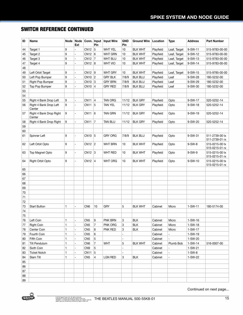
SPIKE SYSTEM AND NODE GUIDE
15THE BEATLES MANUAL 500-55K8-01© 2018 Apple Corps Ltd. All rights reserved. A Beatles™ product lecensed by Apple Corps Ltd. “Beatles” is a trademark of Apple Corps Ltd. “Apple” and the Apple logo are exclusively licensed by Apple Corps Ltd.
SWITCH REFERENCE CONTINUED
Continued on next page...
ID Name Node Node Ext
Conn. Input Pin
Input Wire GND Pin
Ground Wire Location Type Address Part Number
44 Target 1 9 - CN12 5 WHT YEL 10 BLK WHT Playfield Leaf, Target 9-SW-11 515-9783-00-0045 Target 2 9 - CN12 6 WHT GRN 10 BLK WHT Playfield Leaf, Target 9-SW-12 515-9783-00-0046 Target 3 9 - CN12 7 WHT BLU 10 BLK WHT Playfield Leaf, Target 9-SW-13 515-9783-00-0047 Target 4 9 - CN12 8 WHT VIO 10 BLK WHT Playfield Leaf, Target 9-SW-14 515-9783-00-004849 Left Orbit Target 9 - CN12 9 WHT GRY 10 BLK WHT Playfield Leaf, Target 9-SW-15 515-9785-00-0050 Left Pop Bumper 9 - CN10 2 GRY BLK 7/8/9 BLK BLU Playfield Leaf 9-SW-28 180-5232-0051 Right Pop Bumper 9 - CN10 3 GRY BRN 7/8/9 BLK BLU Playfield Leaf 9-SW-29 180-5232-0052 Top Pop Bumper 9 - CN10 4 GRY RED 7/8/9 BLK BLU Playfield Leaf 9-SW-30 180-5232-00535455 Right 4 Bank Drop Left 9 - CN11 4 TAN ORG 11/12 BLK GRY Playfield Opto 9-SW-17 520-5252-1456 Right 4 Bank Drop Left
Center9 - CN11 5 TAN YEL 11/12 BLK GRY Playfield Opto 9-SW-18 520-5252-14
57 Right 4 Bank Drop Right Center
9 - CN11 6 TAN GRN 11/12 BLK GRY Playfield Opto 9-SW-19 520-5252-14
58 Right 4 Bank Drop Right 9 - CN11 7 TAN BLU 11/12 BLK GRY Playfield Opto 9-SW-20 520-5252-14596061 Spinner Left 9 - CN10 5 GRY ORG 7/8/9 BLK BLU Playfield Opto 9-SW-31 511-2739-00 tx
511-2739-01 rx62 Left Orbit Opto 9 - CN12 2 WHT BRN 10 BLK WHT Playfield Opto 9-SW-8 515-0215-00 tx
515-0215-01 rx63 Top Magnet Opto 9 - CN12 3 WHT RED 10 BLK WHT Playfield Opto 9-SW-9 515-0215-00 tx
515-0215-01 rx64 Right Orbit Opto 9 - CN12 4 WHT ORG 10 BLK WHT Playfield Opto 9-SW-10 515-0215-00 tx
515-0215-01 rx656667686970717273 Start Button 1 - CN6 10 GRY 5 BLK WHT Cabinet Micro 1-SW-11 180-5174-00747576 Left Coin 1 - CN5 9 PNK BRN 3 BLK Cabinet Micro 1-SW-1677 Right Coin 1 - CN5 7 PNK ORG 3 BLK Cabinet Micro 1-SW-1878 Center Coin 1 - CN5 8 PNK RED 3 BLK Cabinet Micro 1-SW-1779 Fourth Coin 1 - CN5 6 - Cabinet - 1-SW-1980 Fifth Coin 1 - CN5 5 - Cabinet - 1-SW-2081 Tilt Pendulum 1 - CN6 7 WHT 5 BLK WHT Cabinet Plumb Bob 1-SW-14 516-0007-0082 Sixth Coin 1 - CN9 5 - Cabinet - 1-SW-2183 Ticket Notch 1 - CN11 5 - Cabinet - 1-SW-884 Slam Tilt 1 - CN5 4 LGN RED 3 BLK Cabinet - 1-SW-228586878889
16
SPIKE SYSTEM AND NODE GUIDE
THE BEATLES MANUAL 500-55K8-01© 2018 Apple Corps Ltd. All rights reserved. A Beatles™ product lecensed by Apple Corps Ltd. “Beatles” is a trademark of Apple Corps Ltd. “Apple” and the Apple logo are exclusively licensed by Apple Corps Ltd.
SWITCH REFERENCE CONTINUED
Continued on next page...
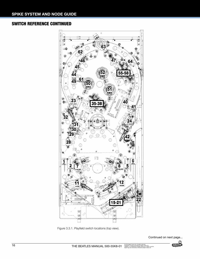
Figure 3.3.1. Playfield switch locations (top view).
SPIKE SYSTEM AND NODE GUIDE
17THE BEATLES MANUAL 500-55K8-01© 2018 Apple Corps Ltd. All rights reserved. A Beatles™ product lecensed by Apple Corps Ltd. “Beatles” is a trademark of Apple Corps Ltd. “Apple” and the Apple logo are exclusively licensed by Apple Corps Ltd.
SWITCH REFERENCE CONTINUED
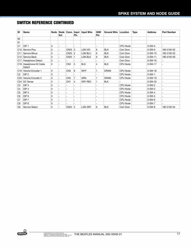
ID Name Node Node Ext
Conn. Input Pin
Input Wire GND Pin
Ground Wire Location Type Address Part Number
9091C1 DIP 1 0 - - - - CPU Node 0-SW-0 -C10 Service Plus 0 - CN25 3 LGN VIO 6 BLK Coin Door 0-SW-9 180-5192-02C11 Service Minus 0 - CN25 2 LGN BLU 6 BLK Coin Door 0-SW-10 180-5192-02C12 Service Back 0 - CN25 1 LGN BLK 6 BLK Coin Door 0-SW-11 180-5192-00C17 Headphone Detect 0 - - - - - - Coin Door 0-SW-16 -C18 Headphone Kit Cable
Detect0 - CN3 5 BLK 4 BLK CPU Node 0-SW-17 -
C19 Volume Encoder 1 0 - CN3 6 WHT 1 DRAIN CPU Node 0-SW-18 -C2 DIP 2 0 - - - - CPU Node 0-SW-1 -C20 Volume Encoder 2 0 - CN3 7 GRN 1 DRAIN CPU Node 0-SW-19 -C24 DC Sense 0 - CN7 4 GRY RED 1 BLK - 0-SW-23 -C3 DIP 3 0 - - - - CPU Node 0-SW-2 -C4 DIP 4 0 - - - - CPU Node 0-SW-3 -C5 DIP 5 0 - - - - CPU Node 0-SW-4 -C6 DIP 6 0 - - - - CPU Node 0-SW-5 -C7 DIP 7 0 - - - - CPU Node 0-SW-6 -C8 DIP 8 0 - - - - CPU Node 0-SW-7 -C9 Service Select 0 - CN25 4 LGN GRY 6 BLK Coin Door 0-SW-8 180-5192-04
18
SPIKE SYSTEM AND NODE GUIDE
THE BEATLES MANUAL 500-55K8-01© 2018 Apple Corps Ltd. All rights reserved. A Beatles™ product lecensed by Apple Corps Ltd. “Beatles” is a trademark of Apple Corps Ltd. “Apple” and the Apple logo are exclusively licensed by Apple Corps Ltd.
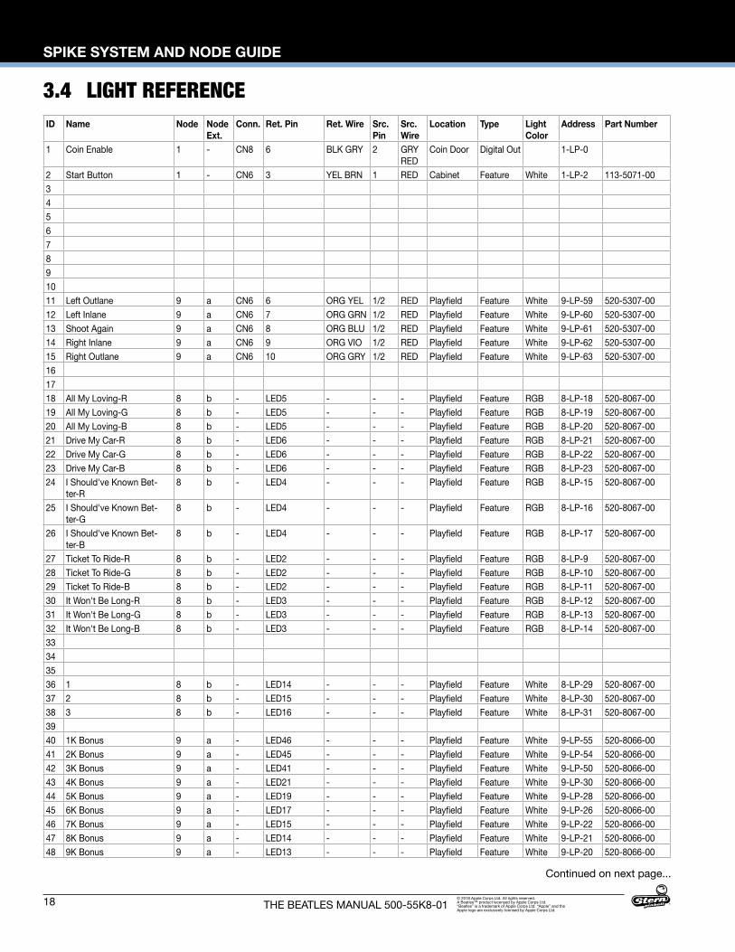
3.4 LIGHT REFERENCE
Continued on next page...
ID Name Node Node Ext.
Conn. Ret. Pin Ret. Wire Src. Pin
Src. Wire
Location Type Light Color
Address Part Number
1 Coin Enable 1 - CN8 6 BLK GRY 2 GRY RED
Coin Door Digital Out 1-LP-0
2 Start Button 1 - CN6 3 YEL BRN 1 RED Cabinet Feature White 1-LP-2 113-5071-0034567891011 Left Outlane 9 a CN6 6 ORG YEL 1/2 RED Playfield Feature White 9-LP-59 520-5307-0012 Left Inlane 9 a CN6 7 ORG GRN 1/2 RED Playfield Feature White 9-LP-60 520-5307-0013 Shoot Again 9 a CN6 8 ORG BLU 1/2 RED Playfield Feature White 9-LP-61 520-5307-0014 Right Inlane 9 a CN6 9 ORG VIO 1/2 RED Playfield Feature White 9-LP-62 520-5307-0015 Right Outlane 9 a CN6 10 ORG GRY 1/2 RED Playfield Feature White 9-LP-63 520-5307-00161718 All My Loving-R 8 b - LED5 - - - Playfield Feature RGB 8-LP-18 520-8067-0019 All My Loving-G 8 b - LED5 - - - Playfield Feature RGB 8-LP-19 520-8067-0020 All My Loving-B 8 b - LED5 - - - Playfield Feature RGB 8-LP-20 520-8067-0021 Drive My Car-R 8 b - LED6 - - - Playfield Feature RGB 8-LP-21 520-8067-0022 Drive My Car-G 8 b - LED6 - - - Playfield Feature RGB 8-LP-22 520-8067-0023 Drive My Car-B 8 b - LED6 - - - Playfield Feature RGB 8-LP-23 520-8067-0024 I Should've Known Bet-
ter-R8 b - LED4 - - - Playfield Feature RGB 8-LP-15 520-8067-00
25 I Should've Known Bet-ter-G
8 b - LED4 - - - Playfield Feature RGB 8-LP-16 520-8067-00
26 I Should've Known Bet-ter-B
8 b - LED4 - - - Playfield Feature RGB 8-LP-17 520-8067-00
27 Ticket To Ride-R 8 b - LED2 - - - Playfield Feature RGB 8-LP-9 520-8067-0028 Ticket To Ride-G 8 b - LED2 - - - Playfield Feature RGB 8-LP-10 520-8067-0029 Ticket To Ride-B 8 b - LED2 - - - Playfield Feature RGB 8-LP-11 520-8067-0030 It Won't Be Long-R 8 b - LED3 - - - Playfield Feature RGB 8-LP-12 520-8067-0031 It Won't Be Long-G 8 b - LED3 - - - Playfield Feature RGB 8-LP-13 520-8067-0032 It Won't Be Long-B 8 b - LED3 - - - Playfield Feature RGB 8-LP-14 520-8067-0033343536 1 8 b - LED14 - - - Playfield Feature White 8-LP-29 520-8067-0037 2 8 b - LED15 - - - Playfield Feature White 8-LP-30 520-8067-0038 3 8 b - LED16 - - - Playfield Feature White 8-LP-31 520-8067-003940 1K Bonus 9 a - LED46 - - - Playfield Feature White 9-LP-55 520-8066-0041 2K Bonus 9 a - LED45 - - - Playfield Feature White 9-LP-54 520-8066-0042 3K Bonus 9 a - LED41 - - - Playfield Feature White 9-LP-50 520-8066-0043 4K Bonus 9 a - LED21 - - - Playfield Feature White 9-LP-30 520-8066-0044 5K Bonus 9 a - LED19 - - - Playfield Feature White 9-LP-28 520-8066-0045 6K Bonus 9 a - LED17 - - - Playfield Feature White 9-LP-26 520-8066-0046 7K Bonus 9 a - LED15 - - - Playfield Feature White 9-LP-22 520-8066-0047 8K Bonus 9 a - LED14 - - - Playfield Feature White 9-LP-21 520-8066-0048 9K Bonus 9 a - LED13 - - - Playfield Feature White 9-LP-20 520-8066-00
SPIKE SYSTEM AND NODE GUIDE
19THE BEATLES MANUAL 500-55K8-01© 2018 Apple Corps Ltd. All rights reserved. A Beatles™ product lecensed by Apple Corps Ltd. “Beatles” is a trademark of Apple Corps Ltd. “Apple” and the Apple logo are exclusively licensed by Apple Corps Ltd.
LIGHT REFERENCE CONTINUED
Continued on next page...
Figure 3.4.1. Playfield light locations (top view).
20
SPIKE SYSTEM AND NODE GUIDE
THE BEATLES MANUAL 500-55K8-01© 2018 Apple Corps Ltd. All rights reserved. A Beatles™ product lecensed by Apple Corps Ltd. “Beatles” is a trademark of Apple Corps Ltd. “Apple” and the Apple logo are exclusively licensed by Apple Corps Ltd.
LIGHT REFERENCE CONTINUED
Continued on next page...
ID Name Node Node Ext.
Conn. Ret. Pin Ret. Wire Src. Pin
Src. Wire
Location Type Light Color
Address Part Number
49 10K Bonus 9 a - LED20 - - - Playfield Feature White 9-LP-29 520-8066-0050 20K Bonus 9 a - LED18 - - - Playfield Feature White 9-LP-27 520-8066-005152 1X Bonus 8 b - LED8 - - - Playfield Feature White 8-LP-25 520-8067-0053 2X Bonus 8 b - LED7 - - - Playfield Feature White 8-LP-24 520-8067-0054 4X Bonus 8 b - LED1 - - - Playfield Feature White 8-LP-8 520-8067-0055565758 Mystery 9 a - LED44 - - - Playfield Feature White 9-LP-53 520-8066-0059 (F)AB 9 a - LED43 - - - Playfield Feature White 9-LP-52 520-8066-0060 F(A)B 9 a - LED42 - - - Playfield Feature White 9-LP-51 520-8066-0061 FA(B) 9 a - LED38 - - - Playfield Feature White 9-LP-47 520-8066-0062 Advance Loops 1 Lt 3Bank 9 a - LED40 - - - Playfield Feature White 9-LP-49 520-8066-0063 Advance Multipliers X Lt
3Bank9 a - LED39 - - - Playfield Feature White 9-LP-48 520-8066-00
64 Score Bonus Lt 3Bank 9 a - LED22 - - - Playfield Feature White 9-LP-31 520-8066-0065 Super Jackpot-R 9 a CN6 3 RED ORG 1/2 RED Playfield Feature White 9-LP-56 520-5333-0066 Super Jackpot-G 9 a CN6 4 GRN ORG 1/2 RED Playfield Feature White 9-LP-57 520-5333-0067 Super Jackpot-B 9 a CN6 5 BLU ORG 1/2 RED Playfield Feature White 9-LP-58 520-5333-006869 Jackpot-R 9 a - LED16 - - - Playfield Feature White 9-LP-23 520-8066-0070 Jackpot-G 9 a - LED16 - - - Playfield Feature White 9-LP-24 520-8066-0071 Jackpot-B 9 a - LED16 - - - Playfield Feature White 9-LP-25 520-8066-007273 Skill Shot Rollover-R 9 - CN14 2 RED BRN 7/8 YEL Playfield Feature White 9-LP-7 520-6824-0X74 Skill Shot Rollover-G 9 - CN14 3 GRN BRN 7/8 YEL Playfield Feature White 9-LP-6 520-6824-0X75 Skill Shot Rollover-B 9 - CN14 4 BLU BRN 7/8 YEL Playfield Feature White 9-LP-5 520-6824-0X7677 John Spinner 9 a CN1 7 RED WHT 1/2/3 RED Playfield Feature White 9-LP-12 520-8065-0078 Paul Spinner 9 a CN1 6 RED GRY 1/2/3 RED Playfield Feature White 9-LP-11 520-8065-0079 George Spinner 9 a CN1 5 RED VIO 1/2/3 RED Playfield Feature White 9-LP-10 520-8065-0080 Ringo Spinner 9 a CN1 4 RED BLU 1/2/3 RED Playfield Feature White 9-LP-9 520-8065-0081828384 (F)OUR 8 c - LED5 - - - Playfield Feature White 8-LP-36 520-8064-0085 F(O)UR 8 c - LED4 - - - Playfield Feature White 8-LP-35 520-8064-0086 FO(U)R 8 c - LED3 - - - Playfield Feature White 8-LP-34 520-8064-0087 FOU(R) 8 c - LED2 - - - Playfield Feature White 8-LP-33 520-8064-0088 Advance loops 2 Cntr
4Bank8 c - LED6 - - - Playfield Feature White 8-LP-37 520-8064-00
89 Advance Multipliers X Cntr 4Bank
8 c - LED7 - - - Playfield Feature White 8-LP-38 520-8064-00
90 Score Bonus Cntr 4Bank 8 c - LED8 - - - Playfield Feature White 8-LP-39 520-8064-0091929394 John Pop Target 9 a CN4 4 BLU YEL 1/2/3 RED Playfield Feature White 9-LP-32 520-5307-0095 Paul Pop Target 9 a CN4 5 BLU GRN 1/2/3 RED Playfield Feature White 9-LP-33 520-5307-0096 George Pop Target 9 a CN4 6 BLU 1/2/3 RED Playfield Feature White 9-LP-34 520-5307-0097 Ringo Pop Target 9 a CN4 7 BLU VIO 1/2/3 RED Playfield Feature White 9-LP-35 520-5307-00
SPIKE SYSTEM AND NODE GUIDE
21THE BEATLES MANUAL 500-55K8-01© 2018 Apple Corps Ltd. All rights reserved. A Beatles™ product lecensed by Apple Corps Ltd. “Beatles” is a trademark of Apple Corps Ltd. “Apple” and the Apple logo are exclusively licensed by Apple Corps Ltd.
LIGHT REFERENCE CONTINUED
Continued on next page...
ID Name Node Node Ext.
Conn. Ret. Pin Ret. Wire Src. Pin
Src. Wire
Location Type Light Color
Address Part Number
98 Advance loops 3 Rt 4Bank 8 d - LED6 - - - Playfield Feature White 8-LP-45 520-8063-0099 Advance Multipliers X Rt
4Bank8 d - LED7 - - - Playfield Feature White 8-LP-46 520-8063-00
100 Score Bonus Rt 4Bank 8 d - LED8 - - - Playfield Feature White 8-LP-47 520-8063-00101102103 Left Orbit Target 9 a CN5 3 BRN ORG 1/2 RED Playfield Feature White 9-LP-40 520-5307-00104 Left Orbit 2X 9 a CN5 4 BRN YEL 1/2 RED Playfield Feature White 9-LP-41 520-8062-00105 Left Orbit 1 9 a CN5 5 BRN GRN 1/2 RED Playfield Feature White 9-LP-42 520-8062-00106 Left Orbit 2 9 a CN5 6 BRN BLU 1/2 RED Playfield Feature White 9-LP-43 520-8062-00107 Left Orbit 3 9 a CN5 7 BRN VIO 1/2 RED Playfield Feature White 9-LP-44 520-8062-00108 Left Orbit 4 9 a CN5 8 BRN GRY 1/2 RED Playfield Feature White 9-LP-45 520-8062-00109 Left Orbit 5 9 a CN5 9 BRN WHT 1/2 RED Playfield Feature White 9-LP-46 520-8062-00110111 Right Orbit Target 9 a CN1 8 GRN RED 1/2/3 RED Playfield Feature White 9-LP-13 520-5307-00112 Right Orbit 2X 9 a CN1 9 GRN YEL 1/2/3 RED Playfield Feature White 9-LP-14 520-8062-00113 Right Orbit 1 9 a CN1 10 GRN 1/2/3 RED Playfield Feature White 9-LP-15 520-8062-00114 Right Orbit 2 9 a CN1 11 GRN BLU 1/2/3 RED Playfield Feature White 9-LP-16 520-8062-00115 Right Orbit 3 9 a CN1 12 GRN VIO 1/2/3 RED Playfield Feature White 9-LP-17 520-8062-00116 Right Orbit 4 9 a CN1 13 GRN GRY 1/2/3 RED Playfield Feature White 9-LP-18 520-8062-00117 Right Orbit 5 9 a CN1 14 GRN WHT 1/2/3 RED Playfield Feature White 9-LP-19 520-8062-00118119120 (1)964 8 d - LED5 - - - Playfield Feature White 8-LP-44 520-8063-00121 1(9)64 8 d - LED4 - - - Playfield Feature White 8-LP-43 520-8063-00122 19(6)4 8 d - LED3 - - - Playfield Feature White 8-LP-42 520-8063-00123 196(4) 8 d - LED2 - - - Playfield Feature White 8-LP-41 520-8063-00124125126127128129130131132133134135136137138139 Coin Door GI 1 - CN5 2 YEL 1 YEL-
WHTCoin Door G.I. White 1-LP-1 112-5033-08
140 Lower Playfield GI 1 8 - CN15 5 RED BLK 1 YEL RED
Playfield G.I. White 8-LP-0 112-5034-WW
141 Lower Playfield GI 2 8 - CN15 6 WHT BLK 2 YEL BLK
Playfield G.I. White 8-LP-1 112-5034-WW 520-7000-00(Bot.Arch) 520-5307(x2)
142 Playfield Upper GI Left 9 - CN15 5 RED BLK 1 YEL RED
Playfield G.I. White 9-LP-0 112-5034-WW
22
SPIKE SYSTEM AND NODE GUIDE
THE BEATLES MANUAL 500-55K8-01© 2018 Apple Corps Ltd. All rights reserved. A Beatles™ product lecensed by Apple Corps Ltd. “Beatles” is a trademark of Apple Corps Ltd. “Apple” and the Apple logo are exclusively licensed by Apple Corps Ltd.
LIGHT REFERENCE CONTINUED
3.5 MOTOR REFERENCE
ID Name Node Node Ext.
Conn. Ret. Pin Ret. Wire Src. Pin
Src. Wire
Location Type Light Color
Address Part Number
143 Playfield Upper GI Right 9 - CN15 6 WHT BLK 2 YEL BLK
Playfield G.I. White 9-LP-1 112-5034-WW
144 Back Panel GI 9 - CN15 7 GRN BLK 3 YEL GRN
Backpanel G.I. White 9-LP-2 112-5034-WW
145146147148149150 Left Sling Flash 8 b CN4 3 ORG 1 RED Playfield Flash White 8-LP-28 520-7000-00151 Right Sling Flash 8 b CN3 3 ORG 1 RED Playfield Flash White 8-LP-26 520-7000-00152 Drum Flash (x3) 8 b - LED10/11/12 - - Playfield Flash White 8-LP-27 520-8067-00153154 Record Flash (x2) 8 c CN3 3 ORG 1 RED Playfield Flash White 8-LP-32 520-7000-00155 Up Right Flipper Flash 9 a CN7 3 ORG 1 RED Playfield Flash White 9-LP-8 520-7000-00156 Left Pop Flash 9 a CN4 8 BRN BLK 1/2/3 RED Playfield Flash White 9-LP-36 520-8059-00157 Right Pop Flash 9 a CN4 9 BRN 1/2/3 RED Playfield Flash White 9-LP-37 520-8059-00158 Top Pop Flash 9 a CN4 10 BRN RED 1/2/3 RED Playfield Flash White 9-LP-38 520-8059-00159 Pop Flash 9 a CN4 11 ORG BLK 1/2/3 RED Playfield Flash White 9-LP-39 113-5045-08160 Top Magnet Flash 8 d CN3 3 ORG 1 RED Playfield Flash White 8-LP-40 520-7000-00161 Left Spinner Flash 9 - CN14 6 ORG BRN 7/8 YEL Playfield Flash White 9-LP-3 520-7000-00162 Right Spinner Flash 9 - CN14 5 ORG WHT 7/8 YEL Playfield Flash White 9-LP-4 520-7000-00163164165166167168169
ID Name Node Node Ext.
Conn. Ret. Pin
Ret. Wire Src. Pin Src. Wire Location Type Light Color
Address Part Number
1 Motor A0 8 - CN14 5 BRN 7/8 YEL Playfield Motor - 8-LP-4 520-5338-002 Motor A1 8 - CN14 4 BRN RED 7/8 YEL Playfield Motor - 8-LP-5 520-5338-00345678910

ELECTRONIC PINOUTS AND SCHEMATICS
23THE BEATLES MANUAL 500-55K8-01© 2018 Apple Corps Ltd. All rights reserved. A Beatles™ product lecensed by Apple Corps Ltd. “Beatles” is a trademark of Apple Corps Ltd. “Apple” and the Apple logo are exclusively licensed by Apple Corps Ltd.
4. ELECTRONIC PINOUTS AND SCHEMATICS4.1 SPIKE-2 CPU NODE 0509-1003-01
CONNECTORSID Connector Type DescriptionCN1 5-Pin .156” Header Backbox 2-channel amplified speaker outCN2 3-Pin .100” Header Console PortCN3 7-Pin .100” Header Headphone connectorCN4 2-Pin .156” Cabinet 1-channel amplified speaker outCN5 7-Pin .100” Header Line In/OutCN6 34 Pin 2.00mm Header LCD display connectorCN7 5-Pin .156” Header 48V supply from main power supplyCN8 6-Pin .100” Header SPI SerialCN9 USB USB connector - for software updates, audit
dumps, and expansion modulesCN9 USB USB connector - for software updates, audit
dumps, and expansion modulesCN10 HDMI HDMI OutCN11 RJ45 SPIKE node bus - to cabinet node N1CN12 RJ45 SPIKE node bus - To Topper accessory KitCN13 SD CARD SD Card connectorCN14 5-Pin .100” Header LCD BacklightCN15 3-Pin .100” Header Backbox LightCN16 4-Pin .100” Header 3.3v / 5v / 12vCN17 ETHERNET ETHERNET connectorCN21 SATA Header SATA connectorCN22 RJ45 SPIKE node bus - to playfield nodeCN25 12-Pin .100” Header Dedicated switch inputs - service, volume
switches
COMPONENTSID NameS1 DIP SwitchesS2 Reset SwitchSD CARD (CN13) For system SD card. Note: only to be removed if
instructed to by Stern Service. BT1 BR1225 3V Lithium battery for game clock between
power cycles
STATUS LEDSLED ID Name Color Description48V +48V Supply In Red ON: Main system power is connected. OFF:
No 48V system power. Check power supply connections, cables, and fuses.
3.3V +3.3V Logic Red ON: Logic power supply is good. OFF: Logic power supply bad, call tech support.
5V +5V Logic Red ON: Logic power supply is good. OFF: Logic power supply bad, call tech support.
12V +12V Backbox Illumination
Red ON: Back box LED power good. OFF: Backbox LED power bad, call tech support.
VA +30V Audio Red ON: Audio power supply is good. OFF: Audio power supply off, call tech support.
VNB +9V Node Bus Red Power for the Node bus. ON: Power for node bus good. OFF: Power to node bus not detected, call tech support.
5V (CPU) +5V Logic Red ON: Logic power supply is good. OFF: Logic power supply bad, call tech support.
SDIO ACT Not Used Red Should remain unlit as it is not currently used.STATUS CPU Heartbeat,
System StatusRed Double blink ~1/2 second: Good, Processor
running. OFF: Processor not running, call tech support.
μSD ACT Activity indicator for micro SD Card
Red Should blink rapidly when reading or writing to micro SD card.
D23 Netbridge Status Red Should blink once every ~1/2 second.
DIRECT SWITCH MAPPING (CN25)The coin-door diagnostic switches are connected directly to the CPU node via the Cabinet Node. Note that both the CPU and Cabinet nodes are required for diagnostic switch operation.
ID Name Conn. Input Pin
Input Wire GND Pin
Ground Wire Location Type Address Part Number
C1 DIP 1 - - - - - CPU Node 0-SW-0 -C2 DIP 2 - - - - - CPU Node 0-SW-1 -C3 DIP 3 - - - - - CPU Node 0-SW-2 -C4 DIP 4 - - - - - CPU Node 0-SW-3 -C5 DIP 5 - - - - - CPU Node 0-SW-4 -C6 DIP 6 - - - - - CPU Node 0-SW-5 -C7 DIP 7 - - - - - CPU Node 0-SW-6 -C8 DIP 8 - - - - - CPU Node 0-SW-7 -C9 Service Select CN25 1 LGN-GRY 11 BLK-WHT Coin Door 0-SW-9 180-5192-04C10 Service Plus CN25 2 LGN-VIO 11 BLK-WHT Coin Door 0-SW-10 180-5192-02C11 Service Minus CN25 3 LGN-BLU 11 BLK-WHT Coin Door 0-SW-11 180-5192-02C12 Service Back CN25 4 LGN-BLK 11 BLK-WHT Coin Door 0-SW-12 180-5192-00
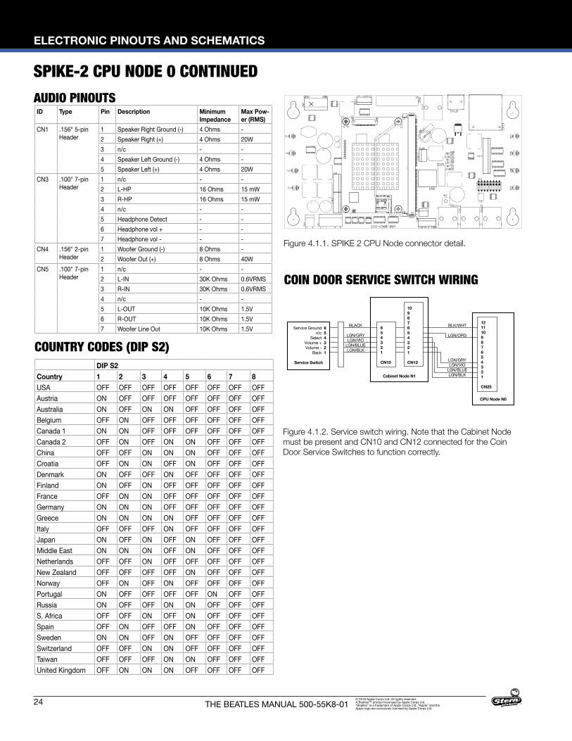
Figure 4.1.1. SPIKE 2 CPU Node connector detail.
24
ELECTRONIC PINOUTS AND SCHEMATICS
THE BEATLES MANUAL 500-55K8-01© 2018 Apple Corps Ltd. All rights reserved. A Beatles™ product lecensed by Apple Corps Ltd. “Beatles” is a trademark of Apple Corps Ltd. “Apple” and the Apple logo are exclusively licensed by Apple Corps Ltd.
AUDIO PINOUTS
COUNTRY CODES (DIP S2)
SPIKE-2 CPU NODE 0 CONTINUED
Figure 4.1.2. Service switch wiring. Note that the Cabinet Node must be present and CN10 and CN12 connected for the Coin Door Service Switches to function correctly.
COIN DOOR SERVICE SWITCH WIRING
DIP S2Country 1 2 3 4 5 6 7 8USA OFF OFF OFF OFF OFF OFF OFF OFFAustria ON OFF OFF OFF OFF OFF OFF OFFAustralia ON OFF ON ON OFF OFF OFF OFFBelgium OFF ON OFF OFF OFF OFF OFF OFFCanada 1 ON ON OFF OFF OFF OFF OFF OFFCanada 2 OFF ON OFF ON ON OFF OFF OFFChina OFF OFF ON ON ON OFF OFF OFFCroatia OFF ON ON OFF ON OFF OFF OFFDenmark ON OFF OFF ON OFF OFF OFF OFFFinland ON OFF ON OFF OFF OFF OFF OFFFrance OFF ON ON OFF OFF OFF OFF OFFGermany ON ON ON OFF OFF OFF OFF OFFGreece ON ON ON ON OFF OFF OFF OFFItaly OFF OFF OFF ON OFF OFF OFF OFFJapan ON OFF ON OFF ON OFF OFF OFFMiddle East ON ON ON OFF ON OFF OFF OFFNetherlands OFF OFF ON OFF OFF OFF OFF OFFNew Zealand OFF OFF OFF OFF ON OFF OFF OFFNorway OFF ON OFF ON OFF OFF OFF OFFPortugal ON OFF OFF OFF OFF ON OFF OFFRussia ON OFF OFF ON ON OFF OFF OFFS. Africa OFF OFF ON OFF ON OFF OFF OFFSpain OFF ON OFF OFF ON OFF OFF OFFSweden ON ON OFF ON OFF OFF OFF OFFSwitzerland OFF OFF ON ON OFF OFF OFF OFFTaiwan OFF OFF OFF ON ON OFF OFF OFFUnited Kingdom OFF ON ON ON OFF OFF OFF OFF
ID Type Pin Description Minimum Impedance
Max Pow-er (RMS)
CN1 .156" 5-pin Header
1 Speaker Right Ground (-) 4 Ohms -2 Speaker Right (+) 4 Ohms 20W3 n/c - -4 Speaker Left Ground (-) 4 Ohms -5 Speaker Left (+) 4 Ohms 20W
CN3 .100" 7-pin Header
1 n/c - -2 L-HP 16 Ohms 15 mW3 R-HP 16 Ohms 15 mW4 n/c - -5 Headphone Detect - -6 Headphone vol + - -7 Headphone vol - - -
CN4 .156" 2-pin Header
1 Woofer Ground (-) 8 Ohms -2 Woofer Out (+) 8 Ohms 40W
CN5 .100" 7-pin Header
1 n/c - -2 L-IN 30K Ohms 0.6VRMS3 R-IN 30K Ohms 0.6VRMS4 n/c - -5 L-OUT 10K Ohms 1.5V6 R-OUT 10K Ohms 1.5V7 Woofer Line Out 10K Ohms 1.5V
ELECTRONIC PINOUTS AND SCHEMATICS
25THE BEATLES MANUAL 500-55K8-01© 2018 Apple Corps Ltd. All rights reserved. A Beatles™ product lecensed by Apple Corps Ltd. “Beatles” is a trademark of Apple Corps Ltd. “Apple” and the Apple logo are exclusively licensed by Apple Corps Ltd.
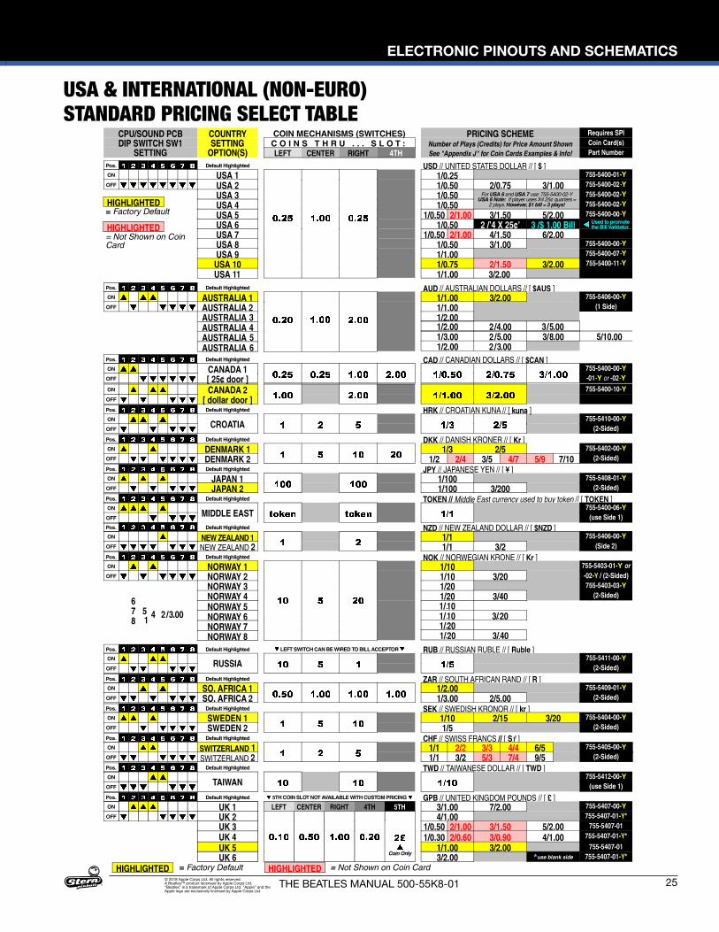
USA & INTERNATIONAL (NON-EURO) STANDARD PRICING SELECT TABLE
*
26
ELECTRONIC PINOUTS AND SCHEMATICS
THE BEATLES MANUAL 500-55K8-01© 2018 Apple Corps Ltd. All rights reserved. A Beatles™ product lecensed by Apple Corps Ltd. “Beatles” is a trademark of Apple Corps Ltd. “Apple” and the Apple logo are exclusively licensed by Apple Corps Ltd.
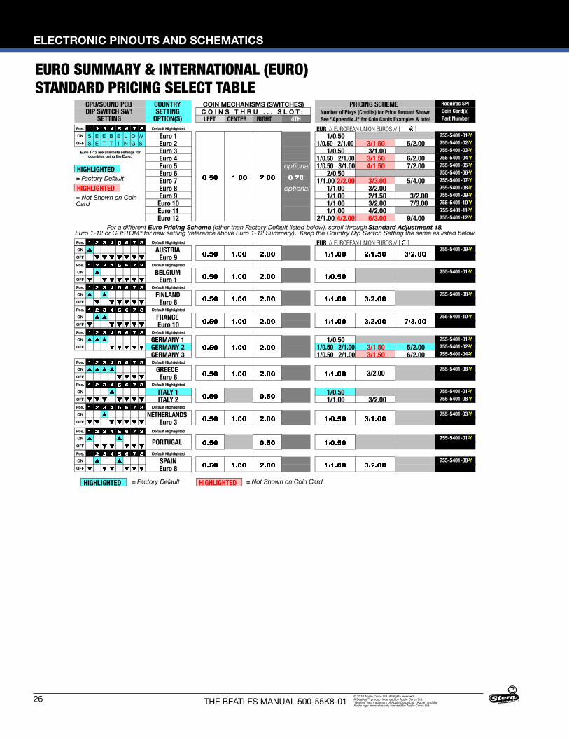
EURO SUMMARY & INTERNATIONAL (EURO) STANDARD PRICING SELECT TABLE
CPU/SOUND PCBDIP SWITCH SW1
SETTING
COUNTRYSETTING
OPTION(S)
COIN MECHANISMS (SWITCHES) PRICING SCHEMENumber of Plays (Credits) for Price Amount ShownSee "Appendix J" for Coin Cards Examples & Info!
Requires SPI
C O I N S T H R U . . . S L O T : Coin Card(s)
LEFT CENTER RIGHT 4TH Part Number
Pos. Default Highlighted EUR // EUROPEAN UNION EUROS // [ ]ON S E E B E L O W Euro 1 1/0.50 755-5401-01-YOFF S E T T I N G S Euro 2 1/0.50 2/1.00 3/1.50 5/2.00 755-5401-02-Y
Euro 1-12 are alternate settings forcountries using the Euro.
Euro 3 1/0.50 3/1.00 755-5401-03-YEuro 4 1/0.50 2/1.00 3/1.50 6/2.00 755-5401-04-Y
= Factory Default
= Not Shown on CoinCard
Euro 5 optional 1/0.50 3/1.00 4/1.50 7/2.00 755-5401-05-YEuro 6 2/0.50 755-5401-06-YEuro 7 1/1.00 2/2.00 3/3.00 5/4.00 755-5401-07-YEuro 8 optional 1/1.00 3/2.00 755-5401-08-YEuro 9 1/1.00 2/1.50 3/2.00 755-5401-09-YEuro 10 1/1.00 3/2.00 7/3.00 755-5401-10-YEuro 11 1/1.00 4/2.00 755-5401-11-YEuro 12 2/1.00 4/2.00 6/3.00 9/4.00 755-5401-12-Y
For a different Euro Pricing Scheme (other than Factory Default listed below), scroll through Standard Adjustment 18:Euro 1-12 or CUSTOM* for new setting (reference above Euro 1-12 Summary). Keep the Country Dip Switch Setting the same as listed below.Pos. Default Highlighted EUR // EUROPEAN UNION EUROS // [ ]ON AUSTRIA 755-5401-09-YOFF Euro 9Pos. Default HighlightedON BELGIUM 755-5401-01-YOFF Euro 1Pos. Default HighlightedON FINLAND 755-5401-08-YOFF Euro 8Pos. Default HighlightedON FRANCE 755-5401-10-YOFF Euro 10Pos. Default HighlightedON GERMANY 1 1/0.50 755-5401-01-YOFF GERMANY 2 1/0.50 2/1.00 3/1.50 5/2.00 755-5401-02-Y
GERMANY 3 1/0.50 2/1.00 3/1.50 6/2.00 755-5401-04-YPos. Default HighlightedON GREECE 3/2.00
755-5401-08-YOFF Euro 8Pos. Default Highlighted
ON ITALY 1 1/0.50 755-5401-01-YOFF ITALY 2 1/1.00 3/2.00 755-5401-08-YPos. Default Highlighted
ON NETHERLANDS 755-5401-03-YOFF Euro 3Pos. Default HighlightedON
PORTUGAL755-5401-01-Y
OFF
Pos. Default HighlightedON SPAIN 755-5401-08-YOFF Euro 8
= Factory Default = Not Shown on Coin CardHIGHLIGHTED
HIGHLIGHTED
HIGHLIGHTED
HIGHLIGHTED
ELECTRONIC PINOUTS AND SCHEMATICS
27THE BEATLES MANUAL 500-55K8-01© 2018 Apple Corps Ltd. All rights reserved. A Beatles™ product lecensed by Apple Corps Ltd. “Beatles” is a trademark of Apple Corps Ltd. “Apple” and the Apple logo are exclusively licensed by Apple Corps Ltd.
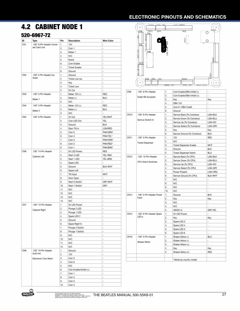
4.2 CABINET NODE 1520-6967-72ID Type Pin Description Wire ColorCN1 .100" 8-Pin Header Univer-
sal Card Link1 12V -2 Coin 1 -3 Meter 1 -4 N/C -5 Notch -6 Coin Enable -7 Ticket Enable -8 Ground -
CN2 .100" 5-Pin Header low ticket
1 Ground -2 Ticket Low sw. -3 Key -4 Ticket Low -5 5V Out -
CN3 .100" 3-Pin Header
Meter 1
1 Meter 12V (+) RED2 Meter (-) BLK3 N/C -
CN4 .100" 3-Pin Header
Meter 2
1 Meter 12V (+) RED2 Meter (-) BLK3 N/C -
CN5 .100" 9-Pin Header 1 5V Out YEL/WHT2 Coin LED Out YEL3 Ground BLK4 Slam Tilt In LGN/RED5 Coin 5 PNK/GRN*6 Coin 4 PNK/YEL*7 Coin 3 PNK/ORN*8 Coin 2 PNK/RED*9 Coin 1 PNK/BRN*
CN6 .100" 14-Pin Header
Cabinet Left
1 5V LED Power RED2 Start 2 LED YEL-RED3 Start 1 LED YEL-BRN4 Spare LED -5 Ground BLK-WHT6 Spare Left -7 Tilt Input WHT8 Door Open -9 Start 2 Switch GRY-WHT10 Start 1 Switch GRY11 N/C -12 N/C -13 N/C -14 N/C -
CN7 .100" 12-Pin Header
Cabinet Right
1 5V LED Power -2 Plunge 2 LED -3 Plunge 1 LED -4 Spare LED 2 -5 Ground -6 Spare Right In -7 Plunge 2 Switch -8 Plunge 1 Switch -9 N/C -10 N/C -11 N/C -12 N/C -
CN8 .100" 10-Pin Header dual row.
Electronic Coin Mech
1 Ground -2 12V -3 Coin 5 -4 Coin 6 -5 N/C -6 Coin Enable/Inhibit (+) -7 Coin 1 -8 Coin 2 -9 Coin 3 -10 Coin 4 -
CN9 .100" 6-Pin Header
Dollar Bill Acceptor
1 Coin Enable/DBA Inhibit (-) -2 Coin Enable/DBA Inhibit (+) -3 Key Key4 DBA 12V -5 Coin 6 / DBA Credit -6 Ground -
CN10 .100" 6-Pin Header
Service Switch In
1 Service Back (To Coindoor) LGN-BLK2 Service Down (To Coindoor) LGN-BLU3 Service Up (To Coindoor) LGN-VIO4 Service Select (To Coindoor) LGN-GRY5 Key Key6 Service Ground (To Coindoor) BLK
CN11 .100" 5-Pin Header
Ticket Dispenser
1 12V RED2 N/C -3 Ticket Dispenser Enable WHT4 Ground BLK5 Ticket Dispenser Notch BLU
CN12 .100" 10-Pin Header
CPU Direct Switches
1 Service Back (To CPU) LGN-BLK2 Service Down (To CPU) LGN-BLU3 Service Up (To CPU) LGN-VIO4 Service Select (To CPU) LGN-GRY5 Power Present LGN-ORG6 Service Ground (To CPU) BLK-WHT7 N/C -8 N/C -9 N/C -10 N/C -
CN14 .156" 5-Pin Header Power Input
1 Ground BLK2 Key Key3 N/C -4 N/C -5 48VDC In GRY-YEL
CN15 .100" 6-Pin Header Spare LED's
1 5V LED Power -2 Key Key3 Spare LED 3 -4 Spare LED 4 -5 Spare LED 5 -6 Spare LED 6 -
CN16 .156" 5-Pin Header
Shaker Motor
1 Shaker Motor (-) BLU2 Shaker Motor (-) -3 Shaker Motor (+) -4 Key Key5 Shaker Motor (+) RED
*Varies by country model
28
ELECTRONIC PINOUTS AND SCHEMATICS
THE BEATLES MANUAL 500-55K8-01© 2018 Apple Corps Ltd. All rights reserved. A Beatles™ product lecensed by Apple Corps Ltd. “Beatles” is a trademark of Apple Corps Ltd. “Apple” and the Apple logo are exclusively licensed by Apple Corps Ltd.
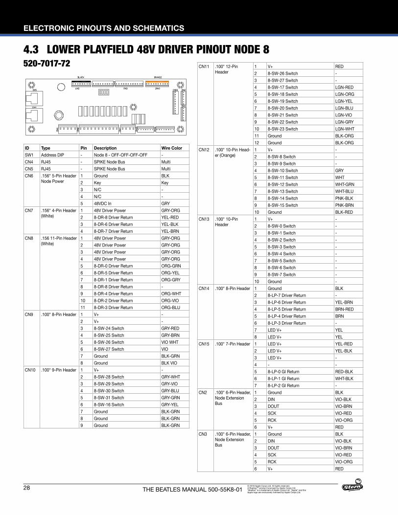
4.3 LOWER PLAYFIELD 48V DRIVER PINOUT NODE 8520-7017-72
ID Type Pin Description Wire ColorSW1 Address DIP - Node 8 - OFF-OFF-OFF-OFF -CN4 RJ45 - SPIKE Node Bus MultiCN5 RJ45 - SPIKE Node Bus MultiCN6 .156" 5-Pin Header
Node Power1 Ground BLK2 Key Key3 N/C -4 N/C -5 48VDC In GRY
CN7 .156" 4-Pin Header (White)
1 48V Driver Power GRY-ORG2 8-DR-8 Driver Return YEL-RED3 8-DR-6 Driver Return YEL-BLK4 8-DR-7 Driver Return YEL-BRN
CN8 .156 11-Pin Header (White)
1 48V Driver Power GRY-ORG2 48V Driver Power GRY-ORG3 48V Driver Power GRY-ORG4 48V Driver Power GRY-ORG5 8-DR-0 Driver Return ORG-GRN6 8-DR-5 Driver Return ORG-YEL7 8-DR-1 Driver Return ORG-GRY8 8-DR-8 Driver Return -9 8-DR-4 Driver Return ORG-WHT10 8-DR-2 Driver Return ORG-VIO11 8-DR-3 Driver Return ORG-BLU
CN9 .100" 8-Pin Header 1 V+ -2 V+ -3 8-SW-24 Switch GRY-RED4 8-SW-25 Switch GRY-BRN5 8-SW-26 Switch VIO WHT6 8-SW-27 Switch VIO7 Ground BLK-GRN8 Ground BLK VIO
CN10 .100" 9-Pin Header 1 V+ -2 8-SW-28 Switch GRY-WHT3 8-SW-29 Switch GRY-VIO4 8-SW-30 Switch GRY-BLU5 8-SW-31 Switch GRY-GRN6 8-SW-16 Switch GRY-YEL7 Ground BLK-GRN8 Ground BLK-GRN9 Ground BLK-GRN
CN11 .100" 12-Pin Header
1 V+ RED2 8-SW-26 Switch -3 8-SW-27 Switch -4 8-SW-17 Switch LGN-RED5 8-SW-18 Switch LGN-ORG6 8-SW-19 Switch LGN-YEL7 8-SW-20 Switch LGN-BLU8 8-SW-21 Switch LGN-VIO9 8-SW-22 Switch LGN-GRY10 8-SW-23 Switch LGN-WHT11 Ground BLK-ORG12 Ground BLK-ORG
CN12 .100" 10-Pin Head-er (Orange)
1 V+ -2 8-SW-8 Switch -3 8-SW-9 Switch -4 8-SW-10 Switch GRY5 8-SW-11 Switch WHT6 8-SW-12 Switch WHT-GRN7 8-SW-13 Switch WHT-BLU8 8-SW-14 Switch PNK-BLK9 8-SW-15 Switch PNK-BRN10 Ground BLK-RED
CN13 .100" 10-Pin Header
1 V+ -2 8-SW-0 Switch -3 8-SW-1 Switch -4 8-SW-2 Switch -5 8-SW-3 Switch -6 8-SW-4 Switch -7 8-SW-5 Switch -8 8-SW-6 Switch -9 8-SW-7 Switch -10 Ground -
CN14 .100" 8-Pin Header 1 Ground BLK2 8-LP-7 Driver Return -3 8-LP-6 Driver Return YEL-BRN4 8-LP-5 Driver Return BRN-RED5 8-LP-4 Driver Return BRN6 8-LP-3 Driver Return -7 LED V+ YEL8 LED V+ YEL
CN15 .100" 7-Pin Header 1 LED V+ YEL-RED2 LED V+ YEL-BLK3 LED V+ -4 - -5 8-LP-0 GI Return RED-BLK6 8-LP-1 GI Return WHT-BLK7 8-LP-2 GI Return -
CN2 .100" 6-Pin Header, Node Extension Bus
1 Ground BLK 2 DIN VIO-BLK3 DOUT VIO-BRN4 SCK VIO-RED5 RCK VIO-ORG6 V+ RED
CN3 .100" 6-Pin Header, Node Extension Bus
1 Ground BLK 2 DIN VIO-BLK3 DOUT VIO-BRN4 SCK VIO-RED5 RCK VIO-ORG6 V+ RED
ELECTRONIC PINOUTS AND SCHEMATICS
29THE BEATLES MANUAL 500-55K8-01© 2018 Apple Corps Ltd. All rights reserved. A Beatles™ product lecensed by Apple Corps Ltd. “Beatles” is a trademark of Apple Corps Ltd. “Apple” and the Apple logo are exclusively licensed by Apple Corps Ltd.
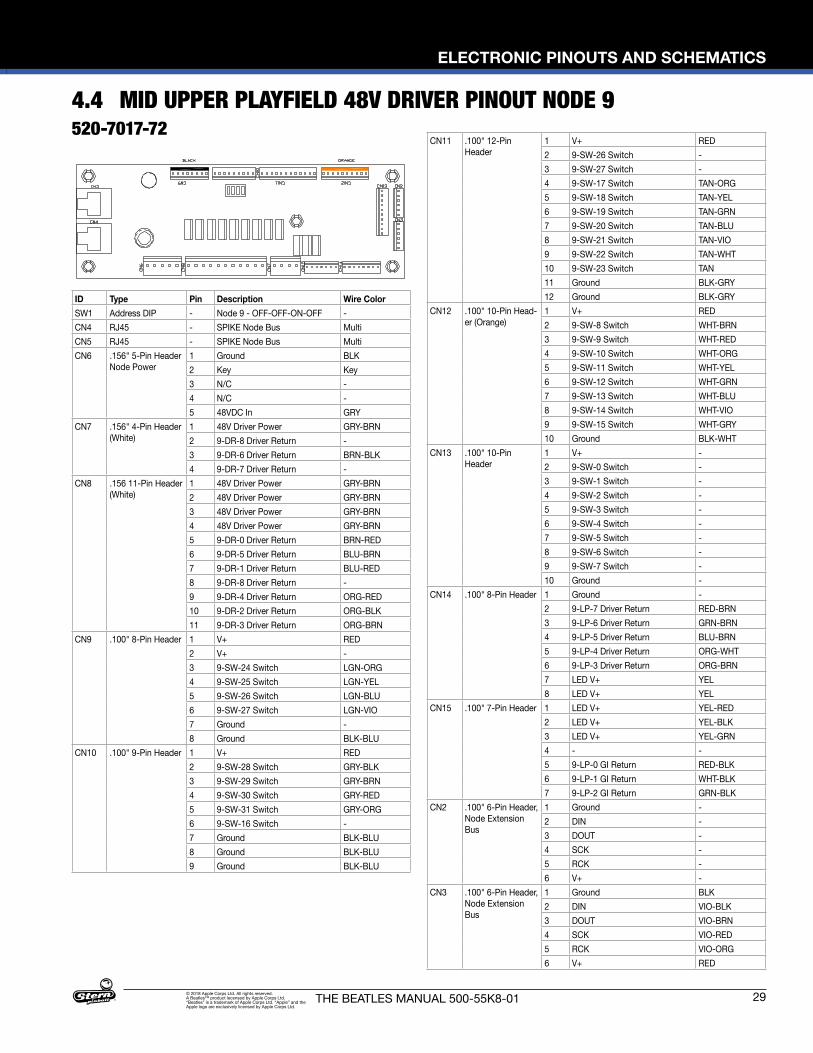
4.4 MID UPPER PLAYFIELD 48V DRIVER PINOUT NODE 9520-7017-72
ID Type Pin Description Wire ColorSW1 Address DIP - Node 9 - OFF-OFF-ON-OFF -CN4 RJ45 - SPIKE Node Bus MultiCN5 RJ45 - SPIKE Node Bus MultiCN6 .156" 5-Pin Header
Node Power1 Ground BLK2 Key Key3 N/C -4 N/C -5 48VDC In GRY
CN7 .156" 4-Pin Header (White)
1 48V Driver Power GRY-BRN2 9-DR-8 Driver Return -3 9-DR-6 Driver Return BRN-BLK4 9-DR-7 Driver Return -
CN8 .156 11-Pin Header (White)
1 48V Driver Power GRY-BRN2 48V Driver Power GRY-BRN3 48V Driver Power GRY-BRN4 48V Driver Power GRY-BRN5 9-DR-0 Driver Return BRN-RED6 9-DR-5 Driver Return BLU-BRN7 9-DR-1 Driver Return BLU-RED8 9-DR-8 Driver Return -9 9-DR-4 Driver Return ORG-RED10 9-DR-2 Driver Return ORG-BLK11 9-DR-3 Driver Return ORG-BRN
CN9 .100" 8-Pin Header 1 V+ RED2 V+ -3 9-SW-24 Switch LGN-ORG4 9-SW-25 Switch LGN-YEL5 9-SW-26 Switch LGN-BLU6 9-SW-27 Switch LGN-VIO7 Ground -8 Ground BLK-BLU
CN10 .100" 9-Pin Header 1 V+ RED2 9-SW-28 Switch GRY-BLK3 9-SW-29 Switch GRY-BRN4 9-SW-30 Switch GRY-RED5 9-SW-31 Switch GRY-ORG6 9-SW-16 Switch -7 Ground BLK-BLU8 Ground BLK-BLU9 Ground BLK-BLU
CN11 .100" 12-Pin Header
1 V+ RED2 9-SW-26 Switch -3 9-SW-27 Switch -4 9-SW-17 Switch TAN-ORG5 9-SW-18 Switch TAN-YEL6 9-SW-19 Switch TAN-GRN7 9-SW-20 Switch TAN-BLU8 9-SW-21 Switch TAN-VIO9 9-SW-22 Switch TAN-WHT10 9-SW-23 Switch TAN11 Ground BLK-GRY12 Ground BLK-GRY
CN12 .100" 10-Pin Head-er (Orange)
1 V+ RED2 9-SW-8 Switch WHT-BRN3 9-SW-9 Switch WHT-RED4 9-SW-10 Switch WHT-ORG5 9-SW-11 Switch WHT-YEL6 9-SW-12 Switch WHT-GRN7 9-SW-13 Switch WHT-BLU8 9-SW-14 Switch WHT-VIO9 9-SW-15 Switch WHT-GRY10 Ground BLK-WHT
CN13 .100" 10-Pin Header
1 V+ -2 9-SW-0 Switch -3 9-SW-1 Switch -4 9-SW-2 Switch -5 9-SW-3 Switch -6 9-SW-4 Switch -7 9-SW-5 Switch -8 9-SW-6 Switch -9 9-SW-7 Switch -10 Ground -
CN14 .100" 8-Pin Header 1 Ground -2 9-LP-7 Driver Return RED-BRN3 9-LP-6 Driver Return GRN-BRN4 9-LP-5 Driver Return BLU-BRN5 9-LP-4 Driver Return ORG-WHT6 9-LP-3 Driver Return ORG-BRN7 LED V+ YEL8 LED V+ YEL
CN15 .100" 7-Pin Header 1 LED V+ YEL-RED2 LED V+ YEL-BLK3 LED V+ YEL-GRN4 - -5 9-LP-0 GI Return RED-BLK6 9-LP-1 GI Return WHT-BLK7 9-LP-2 GI Return GRN-BLK
CN2 .100" 6-Pin Header, Node Extension Bus
1 Ground -2 DIN -3 DOUT -4 SCK -5 RCK -6 V+ -
CN3 .100" 6-Pin Header, Node Extension Bus
1 Ground BLK 2 DIN VIO-BLK3 DOUT VIO-BRN4 SCK VIO-RED5 RCK VIO-ORG6 V+ RED
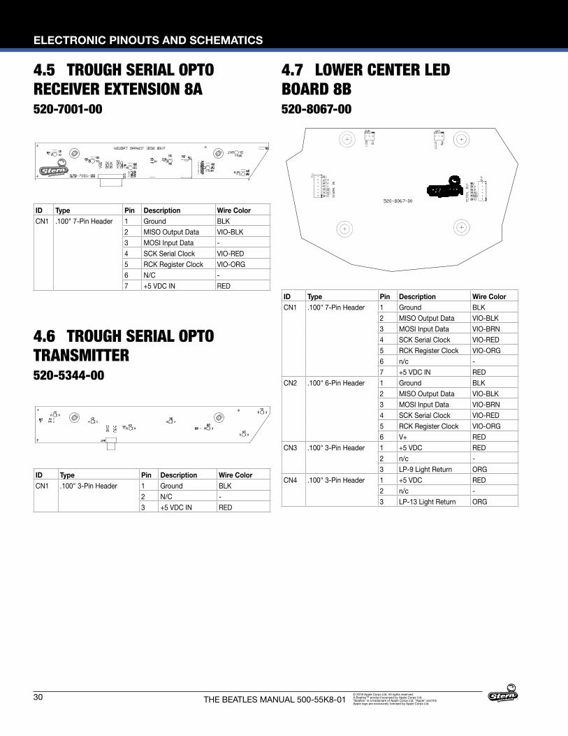
30
ELECTRONIC PINOUTS AND SCHEMATICS
THE BEATLES MANUAL 500-55K8-01© 2018 Apple Corps Ltd. All rights reserved. A Beatles™ product lecensed by Apple Corps Ltd. “Beatles” is a trademark of Apple Corps Ltd. “Apple” and the Apple logo are exclusively licensed by Apple Corps Ltd.
4.5 TROUGH SERIAL OPTO RECEIVER EXTENSION 8A520-7001-00
4.6 TROUGH SERIAL OPTO TRANSMITTER520-5344-00
4.7 LOWER CENTER LED BOARD 8B520-8067-00
ID Type Pin Description Wire ColorCN1 .100" 7-Pin Header 1 Ground BLK
2 MISO Output Data VIO-BLK3 MOSI Input Data -4 SCK Serial Clock VIO-RED5 RCK Register Clock VIO-ORG6 N/C -7 +5 VDC IN RED
ID Type Pin Description Wire ColorCN1 .100" 3-Pin Header 1 Ground BLK
2 N/C -3 +5 VDC IN RED
ID Type Pin Description Wire ColorCN1 .100" 7-Pin Header 1 Ground BLK
2 MISO Output Data VIO-BLK3 MOSI Input Data VIO-BRN4 SCK Serial Clock VIO-RED5 RCK Register Clock VIO-ORG6 n/c -7 +5 VDC IN RED
CN2 .100" 6-Pin Header 1 Ground BLK2 MISO Output Data VIO-BLK3 MOSI Input Data VIO-BRN4 SCK Serial Clock VIO-RED5 RCK Register Clock VIO-ORG6 V+ RED
CN3 .100" 3-Pin Header 1 +5 VDC RED2 n/c -3 LP-9 Light Return ORG
CN4 .100" 3-Pin Header 1 +5 VDC RED2 n/c -3 LP-13 Light Return ORG

ELECTRONIC PINOUTS AND SCHEMATICS
31THE BEATLES MANUAL 500-55K8-01© 2018 Apple Corps Ltd. All rights reserved. A Beatles™ product lecensed by Apple Corps Ltd. “Beatles” is a trademark of Apple Corps Ltd. “Apple” and the Apple logo are exclusively licensed by Apple Corps Ltd.
4.9 DROP TARGET 1 LED BOARD 8D520-8063-00
4.8 DROP TARGET 2 LED BOARD 8C520-8064-00
ID Type Pin Description Wire ColorCN1 .100" 7-Pin Header 1 Ground BLK
2 MISO Output Data VIO-BLK3 MOSI Input Data VIO-BRN4 SCK Serial Clock VIO-RED5 RCK Register Clock VIO-ORG6 n/c -7 +5 VDC IN RED
CN2 .100" 6-Pin Header 1 Ground BLK2 MISO Output Data VIO-BLK3 MOSI Input Data VIO-BRN4 SCK Serial Clock VIO-RED5 RCK Register Clock VIO-ORG6 V+ RED
CN3 .100" 3-Pin Header 1 +5 VDC RED2 n/c -3 LP-1 Light Return ORG
ID Type Pin Description Wire ColorCN1 .100" 7-Pin Header 1 Ground BLK
2 MISO Output Data VIO-BLK3 MOSI Input Data VIO-BRN4 SCK Serial Clock VIO-RED5 RCK Register Clock VIO-ORG6 n/c -7 +5 VDC IN RED
CN2 .100" 6-Pin Header 1 Ground -2 MISO Output Data -3 MOSI Input Data -4 SCK Serial Clock -5 RCK Register Clock -6 V+ -
CN3 .100" 3-Pin Header 1 +5 VDC RED2 n/c -3 LP-1 Light Return ORG
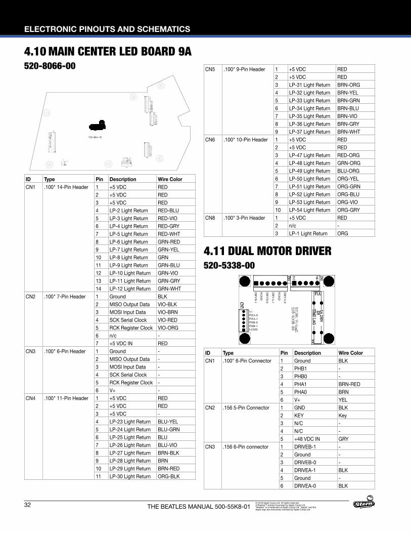
32
ELECTRONIC PINOUTS AND SCHEMATICS
THE BEATLES MANUAL 500-55K8-01© 2018 Apple Corps Ltd. All rights reserved. A Beatles™ product lecensed by Apple Corps Ltd. “Beatles” is a trademark of Apple Corps Ltd. “Apple” and the Apple logo are exclusively licensed by Apple Corps Ltd.
4.10 MAIN CENTER LED BOARD 9A520-8066-00
ID Type Pin Description Wire ColorCN1 .100" 14-Pin Header 1 +5 VDC RED
2 +5 VDC RED3 +5 VDC RED4 LP-2 Light Return RED-BLU5 LP-3 Light Return RED-VIO6 LP-4 Light Return RED-GRY7 LP-5 Light Return RED-WHT8 LP-6 Light Return GRN-RED9 LP-7 Light Return GRN-YEL10 LP-8 Light Return GRN11 LP-9 Light Return GRN-BLU12 LP-10 Light Return GRN-VIO13 LP-11 Light Return GRN-GRY14 LP-12 Light Return GRN-WHT
CN2 .100" 7-Pin Header 1 Ground BLK2 MISO Output Data VIO-BLK3 MOSI Input Data VIO-BRN4 SCK Serial Clock VIO-RED5 RCK Register Clock VIO-ORG6 n/c -7 +5 VDC IN RED
CN3 .100" 6-Pin Header 1 Ground -2 MISO Output Data -3 MOSI Input Data -4 SCK Serial Clock -5 RCK Register Clock -6 V+ -
CN4 .100" 11-Pin Header 1 +5 VDC RED2 +5 VDC RED3 +5 VDC -4 LP-23 Light Return BLU-YEL5 LP-24 Light Return BLU-GRN6 LP-25 Light Return BLU7 LP-26 Light Return BLU-VIO8 LP-27 Light Return BRN-BLK9 LP-28 Light Return BRN10 LP-29 Light Return BRN-RED11 LP-30 Light Return ORG-BLK
CN5 .100" 9-Pin Header 1 +5 VDC RED2 +5 VDC RED3 LP-31 Light Return BRN-ORG4 LP-32 Light Return BRN-YEL5 LP-33 Light Return BRN-GRN6 LP-34 Light Return BRN-BLU7 LP-35 Light Return BRN-VIO8 LP-36 Light Return BRN-GRY9 LP-37 Light Return BRN-WHT
CN6 .100" 10-Pin Header 1 +5 VDC RED2 +5 VDC RED3 LP-47 Light Return RED-ORG4 LP-48 Light Return GRN-ORG5 LP-49 Light Return BLU-ORG6 LP-50 Light Return ORG-YEL7 LP-51 Light Return ORG-GRN8 LP-52 Light Return ORG-BLU9 LP-53 Light Return ORG-VIO10 LP-54 Light Return ORG-GRY
CN8 .100" 3-Pin Header 1 +5 VDC RED2 n/c -3 LP-1 Light Return ORG
4.11 DUAL MOTOR DRIVER520-5338-00
ID Type Pin Description Wire ColorCN1 .100" 6-Pin Connector 1 Ground BLK
2 PHB1 -3 PHB0 -4 PHA1 BRN-RED5 PHA0 BRN6 V+ YEL
CN2 .156 5-Pin Connector 1 GND BLK2 KEY Key3 N/C -4 N/C -5 +48 VDC IN GRY
CN3 .156 6-Pin connector 1 DRIVEB-1 -2 Ground -3 DRIVEB-0 -4 DRIVEA-1 BLK5 Ground -6 DRIVEA-0 BLK
DR
VA
-0
PGN
D
DR
VA
-1
DR
VB
-0
PGN
D
DR
VB
-1
LGNDPHB-1PHB-0PHA-1PHA-0V+
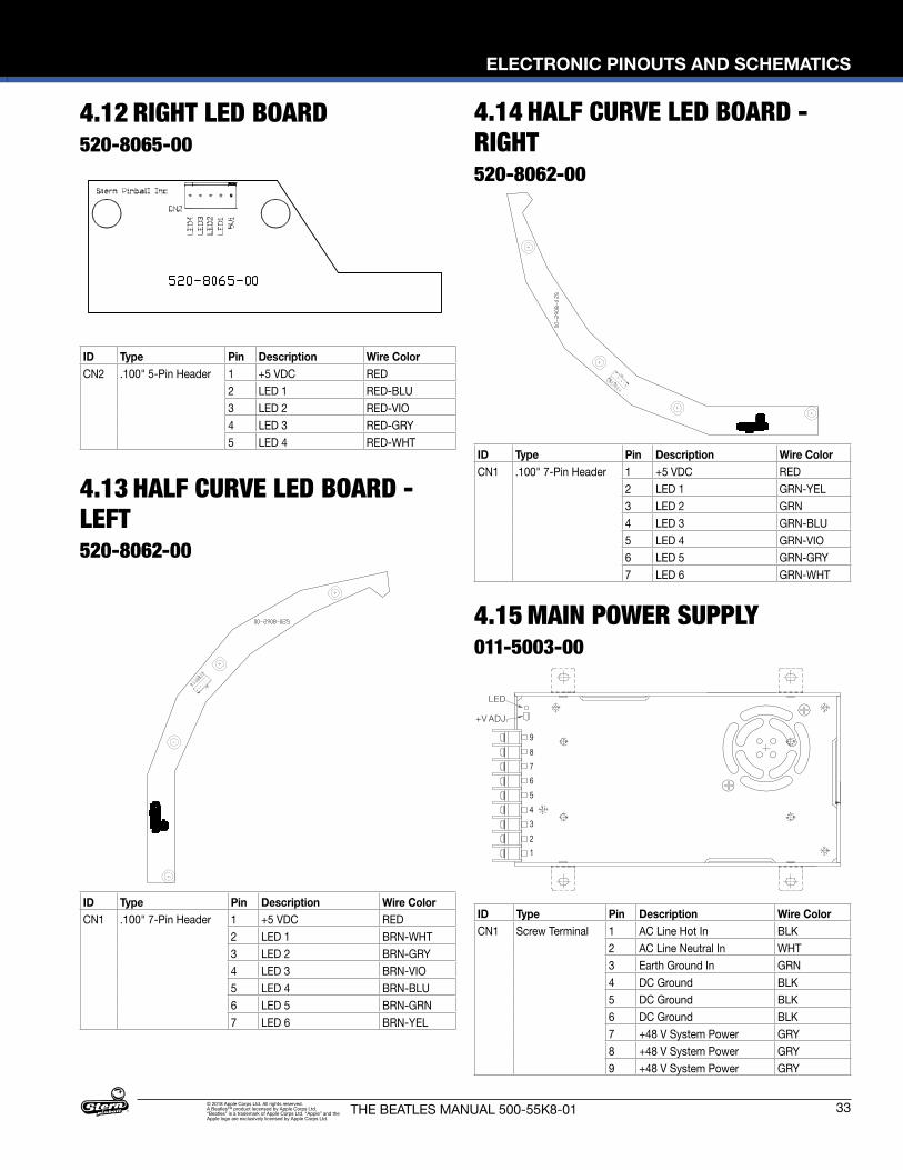
ELECTRONIC PINOUTS AND SCHEMATICS
33THE BEATLES MANUAL 500-55K8-01© 2018 Apple Corps Ltd. All rights reserved. A Beatles™ product lecensed by Apple Corps Ltd. “Beatles” is a trademark of Apple Corps Ltd. “Apple” and the Apple logo are exclusively licensed by Apple Corps Ltd.
LED
+V ADJ.
123456789
4.12 RIGHT LED BOARD520-8065-00
ID Type Pin Description Wire ColorCN1 Screw Terminal 1 AC Line Hot In BLK
2 AC Line Neutral In WHT3 Earth Ground In GRN4 DC Ground BLK5 DC Ground BLK6 DC Ground BLK7 +48 V System Power GRY8 +48 V System Power GRY9 +48 V System Power GRY
ID Type Pin Description Wire ColorCN2 .100" 5-Pin Header 1 +5 VDC RED
2 LED 1 RED-BLU3 LED 2 RED-VIO4 LED 3 RED-GRY5 LED 4 RED-WHT
4.13 HALF CURVE LED BOARD - LEFT520-8062-00
ID Type Pin Description Wire ColorCN1 .100" 7-Pin Header 1 +5 VDC RED
2 LED 1 BRN-WHT3 LED 2 BRN-GRY4 LED 3 BRN-VIO5 LED 4 BRN-BLU6 LED 5 BRN-GRN7 LED 6 BRN-YEL
4.14 HALF CURVE LED BOARD - RIGHT520-8062-00
ID Type Pin Description Wire ColorCN1 .100" 7-Pin Header 1 +5 VDC RED
2 LED 1 GRN-YEL3 LED 2 GRN4 LED 3 GRN-BLU5 LED 4 GRN-VIO6 LED 5 GRN-GRY7 LED 6 GRN-WHT
4.15 MAIN POWER SUPPLY011-5003-00
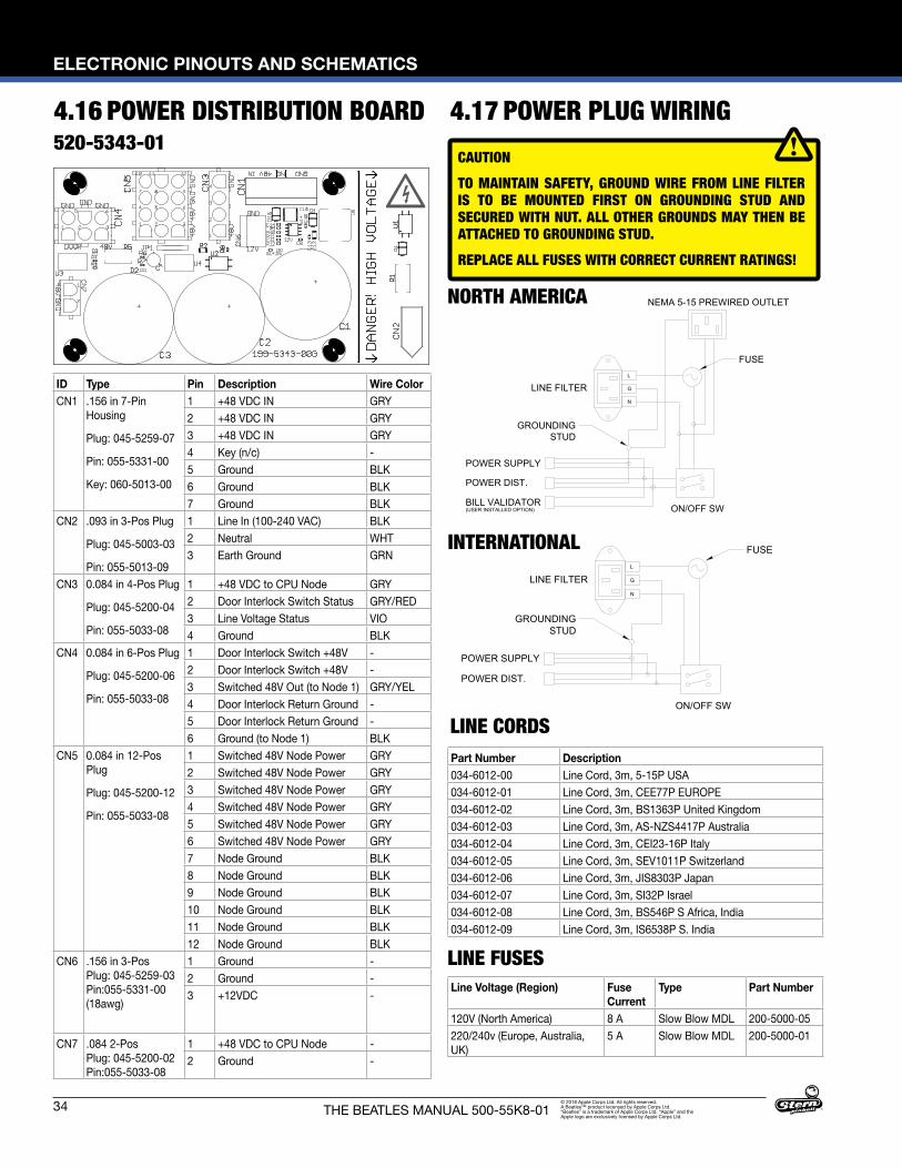
34
ELECTRONIC PINOUTS AND SCHEMATICS
THE BEATLES MANUAL 500-55K8-01© 2018 Apple Corps Ltd. All rights reserved. A Beatles™ product lecensed by Apple Corps Ltd. “Beatles” is a trademark of Apple Corps Ltd. “Apple” and the Apple logo are exclusively licensed by Apple Corps Ltd.
4.16 POWER DISTRIBUTION BOARD520-5343-01
GROUNDINGSTUD
POWER SUPPLY
POWER DIST.
INTERNATIONAL
XXX-XXXX-XX
05/02/14
1:1
SPIKE BB
1.00" 2.00"
LINE FILTER
ON/OFF SW
FUSEL
G
N
*MFG NOTES:
1. ALL DISCREET WIRE IS 16AWG 600V, UL 1015, CSA TYPE TEW.2. GROUND WIRE FROM LINE FILTER IS TO BE MOUNTED FIRST ON GROUNDING STUD
AND SECURED WITH NUT. ALL OTHER GROUNDS MAY THEN BE ATTACHED TOGROUNDING STUD.
3. CABLE ARE TO BE MANUFACTURED IN A UL CERTIFIED FACILITY. VENDOR IS TOPROVIDE A SIGNED U.L. CERTIFICATE OF COMPLIANCE WITH FIRST ARTICLE.
INTERNATIONAL
GROUNDINGSTUD
POWER SUPPLY
POWER DIST.
BILL VALIDATOR
NORTH AMERICA
XXX-XXXX-XX
05/02/14
1:1AC WIRING DIAGRAM-N. AMERICA1.00" 2.00"
LINE FILTER
NEMA 5-15 PREWIRED OUTLET
ON/OFF SW
FUSE
(USER INSTALLED OPTION)
L
G
N
*MFG NOTES:
1. ALL DISCREET WIRE IS 16AWG 600V, UL 1015, CSA TYPE TEW.2. NEMA 5-15 OUTLET HAS 14AWG 600V WIRE, UL 1015, CSA TYPE TEW.3. GROUND WIRE FROM LINE FILTER IS TO BE MOUNTED FIRST ON GROUNDING STUD
AND SECURED WITH NUT. ALL OTHER GROUNDS MAY THEN BE ATTACHED TOGROUNDING STUD.
4. CABLE ARE TO BE MANUFACTURED IN A UL CERTIFIED FACILITY. VENDOR IS TOPROVIDE A SIGNED U.L. CERTIFICATE OF COMPLIANCE WITH FIRST ARTICLE.
SPIKE BB
NORTH AMERICA
LINE FUSES
LINE CORDS
Line Voltage (Region) Fuse Current
Type Part Number
120V (North America) 8 A Slow Blow MDL 200-5000-05220/240v (Europe, Australia, UK)
5 A Slow Blow MDL 200-5000-01
CAUTIONTO MAINTAIN SAFETY, GROUND WIRE FROM LINE FILTER IS TO BE MOUNTED FIRST ON GROUNDING STUD AND SECURED WITH NUT. ALL OTHER GROUNDS MAY THEN BE ATTACHED TO GROUNDING STUD. REPLACE ALL FUSES WITH CORRECT CURRENT RATINGS!
Part Number Description034-6012-00 Line Cord, 3m, 5-15P USA034-6012-01 Line Cord, 3m, CEE77P EUROPE034-6012-02 Line Cord, 3m, BS1363P United Kingdom034-6012-03 Line Cord, 3m, AS-NZS4417P Australia034-6012-04 Line Cord, 3m, CEI23-16P Italy034-6012-05 Line Cord, 3m, SEV1011P Switzerland034-6012-06 Line Cord, 3m, JIS8303P Japan034-6012-07 Line Cord, 3m, SI32P Israel034-6012-08 Line Cord, 3m, BS546P S Africa, India034-6012-09 Line Cord, 3m, IS6538P S. India
4.17 POWER PLUG WIRING
ID Type Pin Description Wire ColorCN1 .156 in 7-Pin
Housing
Plug: 045-5259-07
Pin: 055-5331-00
Key: 060-5013-00
1 +48 VDC IN GRY2 +48 VDC IN GRY3 +48 VDC IN GRY4 Key (n/c) -5 Ground BLK6 Ground BLK7 Ground BLK
CN2 .093 in 3-Pos Plug
Plug: 045-5003-03
Pin: 055-5013-09
1 Line In (100-240 VAC) BLK2 Neutral WHT3 Earth Ground GRN
CN3 0.084 in 4-Pos Plug
Plug: 045-5200-04
Pin: 055-5033-08
1 +48 VDC to CPU Node GRY2 Door Interlock Switch Status GRY/RED3 Line Voltage Status VIO4 Ground BLK
CN4 0.084 in 6-Pos Plug
Plug: 045-5200-06
Pin: 055-5033-08
1 Door Interlock Switch +48V -2 Door Interlock Switch +48V -3 Switched 48V Out (to Node 1) GRY/YEL4 Door Interlock Return Ground -5 Door Interlock Return Ground -6 Ground (to Node 1) BLK
CN5 0.084 in 12-Pos Plug
Plug: 045-5200-12
Pin: 055-5033-08
1 Switched 48V Node Power GRY2 Switched 48V Node Power GRY3 Switched 48V Node Power GRY4 Switched 48V Node Power GRY5 Switched 48V Node Power GRY6 Switched 48V Node Power GRY7 Node Ground BLK8 Node Ground BLK9 Node Ground BLK10 Node Ground BLK11 Node Ground BLK12 Node Ground BLK
CN6 .156 in 3-Pos Plug: 045-5259-03 Pin:055-5331-00 (18awg)
1 Ground -2 Ground -3 +12VDC -
CN7 .084 2-Pos Plug: 045-5200-02 Pin:055-5033-08
1 +48 VDC to CPU Node -2 Ground -

PARTS REFERENCE
35THE BEATLES MANUAL 500-55K8-01© 2018 Apple Corps Ltd. All rights reserved. A Beatles™ product lecensed by Apple Corps Ltd. “Beatles” is a trademark of Apple Corps Ltd. “Apple” and the Apple logo are exclusively licensed by Apple Corps Ltd.
5.1 PLAYFIELD RUBBER PARTS RUBBER O-RINGS
1”3/4”
1-1/4”1-1/2”1-3/4”
2”
2-1/2”2-3/4”
3”
3-1/2”
3/8”7/16”
5/16” 3/16”
7/16” OD
3/8” OD
5. PARTS REFERENCE
8
4
11
12
5
2
8
12
7
3
6
7
7
1
1
2
2
2
12
12
Figure 5.1.1. Rubber o-ring part locations
Figure 5.1.2. Rubber o-ring part numbers and usage. ID: Inner Diameter, OD: Outer Diameter, Durometer: Higher number is firmer, less bounce, and more durable.
Figure 5.1.3. Other rubber part numbers and usage
5.2 RUBBER SIZE CHART
Figure 5.2.1. Rubber ring inner diameter sizing tool. Hold ring up to chart and read largest size on inside of ring. Dimensions are Inner Diameter (ID) unless otherwise noted as Outer Diameter (OD).
ID Qty Size (ID) Size (OD) Durometer Color Part Number1 3 3/16" 50 White 545-5348-512 6 5/16" 50 White 545-5348-523 1 1" 50 White 545-5348-554 1 1-1/4" 50 White 545-5348-565 1 1-1/2" 50 White 545-5348-576 1 1-3/4" 50 White 545-5348-617 3 2" 50 White 545-5348-588 2 2-1/2" 50 White 545-5348-59
ID Qty Description Color Part Number11 1 Plunger Tip Black 545-5276-0012 4 Flipper Rubber Red 545-5277-2213 1 Bumper Pad (Sub assemblies) Black 545-5105-0014 4 Bumper Pad (Flippers) Black 545-5428-00
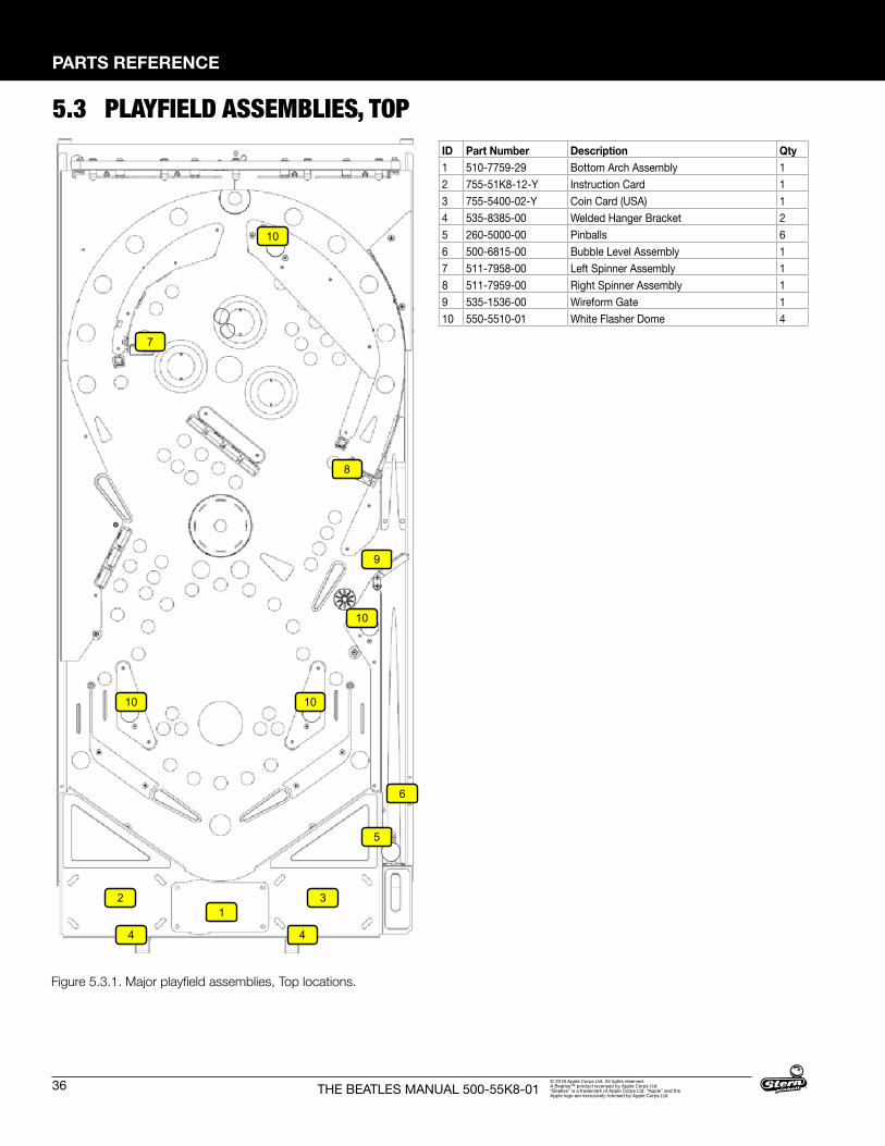
36
PARTS REFERENCE
THE BEATLES MANUAL 500-55K8-01© 2018 Apple Corps Ltd. All rights reserved. A Beatles™ product lecensed by Apple Corps Ltd. “Beatles” is a trademark of Apple Corps Ltd. “Apple” and the Apple logo are exclusively licensed by Apple Corps Ltd.
5.3 PLAYFIELD ASSEMBLIES, TOP
Figure 5.3.1. Major playfield assemblies, Top locations.
12 3
6
4
9
4
5
7
8
10 10
10
10
ID Part Number Description Qty1 510-7759-29 Bottom Arch Assembly 12 755-51K8-12-Y Instruction Card 13 755-5400-02-Y Coin Card (USA) 14 535-8385-00 Welded Hanger Bracket 25 260-5000-00 Pinballs 66 500-6815-00 Bubble Level Assembly 17 511-7958-00 Left Spinner Assembly 18 511-7959-00 Right Spinner Assembly 19 535-1536-00 Wireform Gate 110 550-5510-01 White Flasher Dome 4
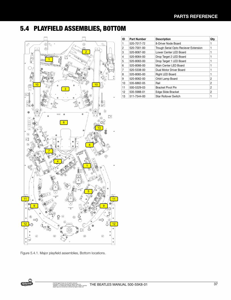
PARTS REFERENCE
37THE BEATLES MANUAL 500-55K8-01© 2018 Apple Corps Ltd. All rights reserved. A Beatles™ product lecensed by Apple Corps Ltd. “Beatles” is a trademark of Apple Corps Ltd. “Apple” and the Apple logo are exclusively licensed by Apple Corps Ltd.
5.4 PLAYFIELD ASSEMBLIES, BOTTOM
Figure 5.4.1. Major playfield assemblies, Bottom locations.
3
4
7
5
2
1
6
1
8
9 9
10 10
11 11
12 12
13
ID Part Number Description Qty1 520-7017-72 8-Driver Node Board 12 520-7001-00 Trough Serial Opto Reciever Extension 13 520-8067-00 Lower Center LED Board 14 520-8064-00 Drop Target 2 LED Board 15 520-8063-00 Drop Target 1 LED Board 16 520-8066-00 Main Center LED Board 17 520-5338-00 Dual Motor Driver Board 18 520-8065-00 Right LED Board 19 520-8062-00 Orbit Lamp Board 210 535-6862-05 Rail 211 500-5329-03 Bracket Pivot Pin 212 535-5988-01 Edge Slide Bracket 213 511-7544-00 Star Rollover Switch 1
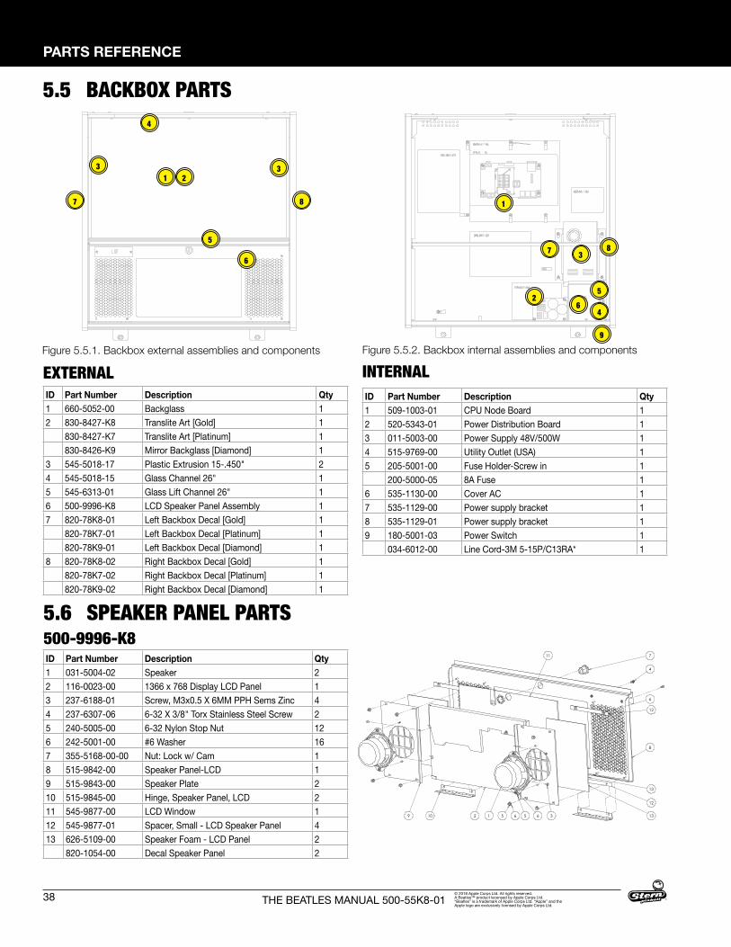
38
PARTS REFERENCE
THE BEATLES MANUAL 500-55K8-01© 2018 Apple Corps Ltd. All rights reserved. A Beatles™ product lecensed by Apple Corps Ltd. “Beatles” is a trademark of Apple Corps Ltd. “Apple” and the Apple logo are exclusively licensed by Apple Corps Ltd.
EXTERNALFigure 5.5.1. Backbox external assemblies and components Figure 5.5.2. Backbox internal assemblies and components
5.5 BACKBOX PARTS
INTERNAL
5.6 SPEAKER PANEL PARTS500-9996-K8
LCD BACKBOXDOMESTIC VERSION500-9995-XX
LCD BACKBOX5009995-XX
1
2
3
4
56
7 8
133
4
5
6
7 8
2
9
9 10 2 1 5 6
12
13
8
12
6
4
7
13
11
35 6
SPEAKER/LCD PANEL PARTS500-9996-XX
ID Part Number Description Qty1 660-5052-00 Backglass 12 830-8427-K8 Translite Art [Gold] 1
830-8427-K7 Translite Art [Platinum] 1830-8426-K9 Mirror Backglass [Diamond] 1
3 545-5018-17 Plastic Extrusion 15-.450" 24 545-5018-15 Glass Channel 26" 15 545-6313-01 Glass Lift Channel 26" 16 500-9996-K8 LCD Speaker Panel Assembly 17 820-78K8-01 Left Backbox Decal [Gold] 1
820-78K7-01 Left Backbox Decal [Platinum] 1820-78K9-01 Left Backbox Decal [Diamond] 1
8 820-78K8-02 Right Backbox Decal [Gold] 1820-78K7-02 Right Backbox Decal [Platinum] 1820-78K9-02 Right Backbox Decal [Diamond] 1
ID Part Number Description Qty1 509-1003-01 CPU Node Board 12 520-5343-01 Power Distribution Board 13 011-5003-00 Power Supply 48V/500W 14 515-9769-00 Utility Outlet (USA) 15 205-5001-00 Fuse Holder-Screw in 1
200-5000-05 8A Fuse 16 535-1130-00 Cover AC 17 535-1129-00 Power supply bracket 18 535-1129-01 Power supply bracket 19 180-5001-03 Power Switch 1
034-6012-00 Line Cord-3M 5-15P/C13RA* 1
ID Part Number Description Qty1 031-5004-02 Speaker 22 116-0023-00 1366 x 768 Display LCD Panel 13 237-6188-01 Screw, M3x0.5 X 6MM PPH Sems Zinc 44 237-6307-06 6-32 X 3/8" Torx Stainless Steel Screw 25 240-5005-00 6-32 Nylon Stop Nut 126 242-5001-00 #6 Washer 167 355-5168-00-00 Nut: Lock w/ Cam 18 515-9842-00 Speaker Panel-LCD 19 515-9843-00 Speaker Plate 210 515-9845-00 Hinge, Speaker Panel, LCD 211 545-9877-00 LCD Window 112 545-9877-01 Spacer, Small - LCD Speaker Panel 413 626-5109-00 Speaker Foam - LCD Panel 2
820-1054-00 Decal Speaker Panel 2
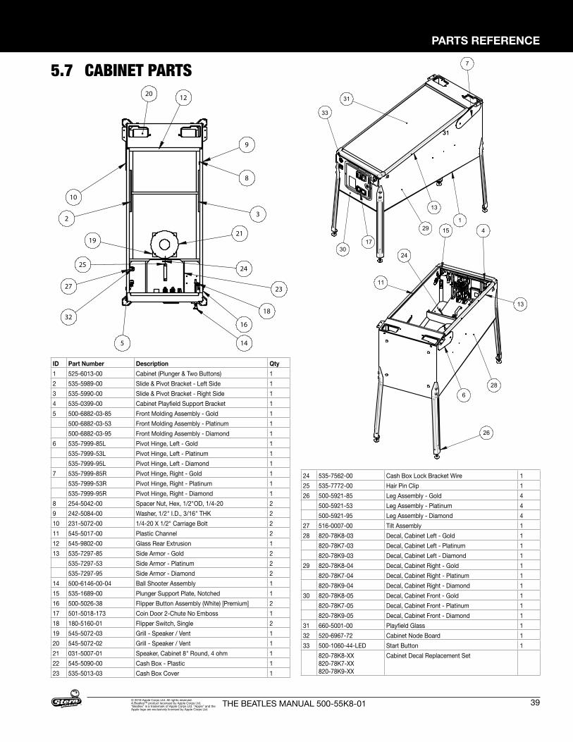
PARTS REFERENCE
39THE BEATLES MANUAL 500-55K8-01© 2018 Apple Corps Ltd. All rights reserved. A Beatles™ product lecensed by Apple Corps Ltd. “Beatles” is a trademark of Apple Corps Ltd. “Apple” and the Apple logo are exclusively licensed by Apple Corps Ltd.
5.7 CABINET PARTS
8
9
3
21
18
16
14
23
5
25
27
32
19
2
24
10
20 12
31
7
13
1
30
29
4
24
15
11
628
26
13
17
3131
33
8
9
3
21
18
16
14
23
5
25
27
32
19
2
24
10
20 12
31
7
13
1
30
29
4
24
15
11
628
26
13
17
3131
33
8
9
3
21
18
16
14
23
5
25
27
32
19
2
24
10
20 12
31
7
13
1
30
29
4
24
15
11
6
28
26
13
17
ID Part Number Description Qty1 525-6013-00 Cabinet (Plunger & Two Buttons) 12 535-5989-00 Slide & Pivot Bracket - Left Side 13 535-5990-00 Slide & Pivot Bracket - Right Side 14 535-0399-00 Cabinet Playfield Support Bracket 15 500-6882-03-85 Front Molding Assembly - Gold 1
500-6882-03-53 Front Molding Assembly - Platinum 1500-6882-03-95 Front Molding Assembly - Diamond 1
6 535-7999-85L Pivot Hinge, Left - Gold 1535-7999-53L Pivot Hinge, Left - Platinum 1535-7999-95L Pivot Hinge, Left - Diamond 1
7 535-7999-85R Pivot Hinge, Right - Gold 1535-7999-53R Pivot Hinge, Right - Platinum 1535-7999-95R Pivot Hinge, Right - Diamond 1
8 254-5042-00 Spacer Nut, Hex, 1/2"OD, 1/4-20 29 242-5084-00 Washer, 1/2" I.D., 3/16" THK 210 231-5072-00 1/4-20 X 1/2" Carriage Bolt 211 545-5017-00 Plastic Channel 212 545-9802-00 Glass Rear Extrusion 113 535-7297-85 Side Armor - Gold 2
535-7297-53 Side Armor - Platinum 2535-7297-95 Side Armor - Diamond 2
14 500-6146-00-04 Ball Shooter Assembly 115 535-1689-00 Plunger Support Plate, Notched 116 500-5026-38 Flipper Button Assembly (White) [Premium] 217 501-5018-173 Coin Door 2-Chute No Emboss 118 180-5160-01 Flipper Switch, Single 219 545-5072-03 Grill - Speaker / Vent 120 545-5072-02 Grill - Speaker / Vent 121 031-5007-01 Speaker, Cabinet 8" Round, 4 ohm 122 545-5090-00 Cash Box - Plastic 123 535-5013-03 Cash Box Cover 1
24 535-7562-00 Cash Box Lock Bracket Wire 125 535-7772-00 Hair Pin Clip 126 500-5921-85 Leg Assembly - Gold 4
500-5921-53 Leg Assembly - Platinum 4500-5921-95 Leg Assembly - Diamond 4
27 516-0007-00 Tilt Assembly 128 820-78K8-03 Decal, Cabinet Left - Gold 1
820-78K7-03 Decal, Cabinet Left - Platinum 1820-78K9-03 Decal, Cabinet Left - Diamond 1
29 820-78K8-04 Decal, Cabinet Right - Gold 1820-78K7-04 Decal, Cabinet Right - Platinum 1820-78K9-04 Decal, Cabinet Right - Diamond 1
30 820-78K8-05 Decal, Cabinet Front - Gold 1820-78K7-05 Decal, Cabinet Front - Platinum 1820-78K9-05 Decal, Cabinet Front - Diamond 1
31 660-5001-00 Playfield Glass 132 520-6967-72 Cabinet Node Board 133 500-1060-44-LED Start Button 1
820-78K8-XX 820-78K7-XX 820-78K9-XX
Cabinet Decal Replacement Set
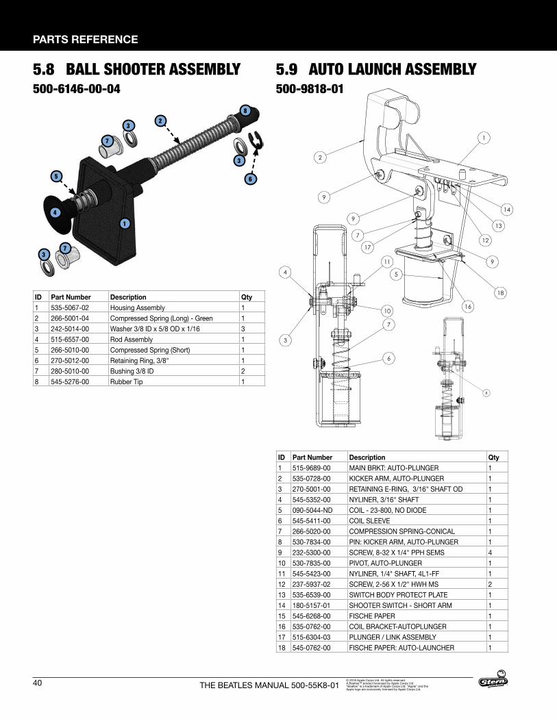
40
PARTS REFERENCE
THE BEATLES MANUAL 500-55K8-01© 2018 Apple Corps Ltd. All rights reserved. A Beatles™ product lecensed by Apple Corps Ltd. “Beatles” is a trademark of Apple Corps Ltd. “Apple” and the Apple logo are exclusively licensed by Apple Corps Ltd.
5.8 BALL SHOOTER ASSEMBLY500-6146-00-04
14
5
32
8
6
2
9
1
5
7
17
14
139
9
16
12
18
17
8
10
3
4
11
6
7
2
9
1
5
7
17
14
139
9
16
12
18
17
8
10
3
4
11
6
7
2
9
1
5
7
17
14
139
9
16
12
18
17
8
10
3
4
11
6
7
ID Part Number Description Qty1 515-9689-00 MAIN BRKT: AUTO-PLUNGER 12 535-0728-00 KICKER ARM, AUTO-PLUNGER 13 270-5001-00 RETAINING E-RING, 3/16" SHAFT OD 14 545-5352-00 NYLINER, 3/16" SHAFT 15 090-5044-ND COIL - 23-800, NO DIODE 16 545-5411-00 COIL SLEEVE 17 266-5020-00 COMPRESSION SPRING-CONICAL 18 530-7834-00 PIN: KICKER ARM, AUTO-PLUNGER 19 232-5300-00 SCREW, 8-32 X 1/4" PPH SEMS 410 530-7835-00 PIVOT, AUTO-PLUNGER 111 545-5423-00 NYLINER, 1/4" SHAFT, 4L1-FF 112 237-5937-02 SCREW, 2-56 X 1/2" HWH MS 213 535-6539-00 SWITCH BODY PROTECT PLATE 114 180-5157-01 SHOOTER SWITCH - SHORT ARM 115 545-6268-00 FISCHE PAPER 116 535-0762-00 COIL BRACKET-AUTOPLUNGER 117 515-6304-03 PLUNGER / LINK ASSEMBLY 118 545-0762-00 FISCHE PAPER: AUTO-LAUNCHER 1
5.9 AUTO LAUNCH ASSEMBLY500-9818-01
ID Part Number Description Qty1 535-5067-02 Housing Assembly 12 266-5001-04 Compressed Spring (Long) - Green 13 242-5014-00 Washer 3/8 ID x 5/8 OD x 1/16 34 515-6557-00 Rod Assembly 15 266-5010-00 Compressed Spring (Short) 16 270-5012-00 Retaining Ring, 3/8" 17 280-5010-00 Bushing 3/8 ID 28 545-5276-00 Rubber Tip 1
3
3
7
7
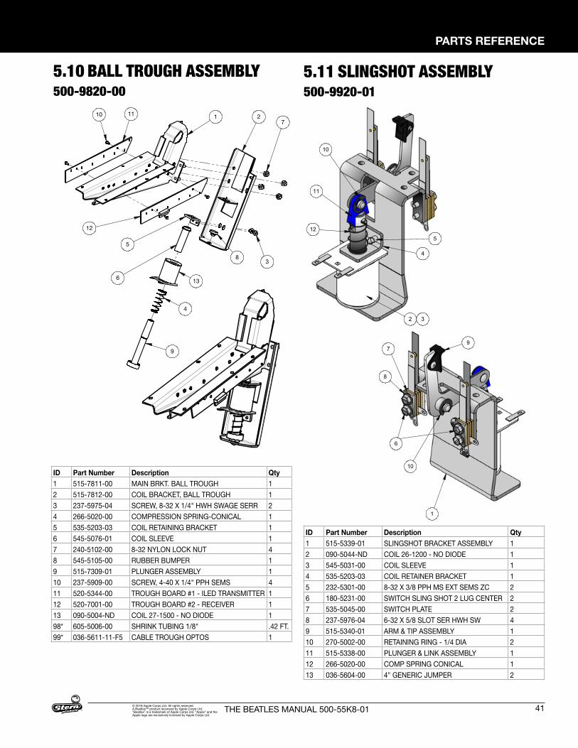
PARTS REFERENCE
41THE BEATLES MANUAL 500-55K8-01© 2018 Apple Corps Ltd. All rights reserved. A Beatles™ product lecensed by Apple Corps Ltd. “Beatles” is a trademark of Apple Corps Ltd. “Apple” and the Apple logo are exclusively licensed by Apple Corps Ltd.
1110 1
12
9
4
136
5
3
27
8
1110
1
12
9
4
13
6
53
2 7
8
5.10 BALL TROUGH ASSEMBLY500-9820-00
5.11 SLINGSHOT ASSEMBLY500-9920-01
ID Part Number Description Qty1 515-5339-01 SLINGSHOT BRACKET ASSEMBLY 12 090-5044-ND COIL 26-1200 - NO DIODE 13 545-5031-00 COIL SLEEVE 14 535-5203-03 COIL RETAINER BRACKET 15 232-5301-00 8-32 X 3/8 PPH MS EXT SEMS ZC 26 180-5231-00 SWITCH SLING SHOT 2 LUG CENTER 27 535-5045-00 SWITCH PLATE 28 237-5976-04 6-32 X 5/8 SLOT SER HWH SW 49 515-5340-01 ARM & TIP ASSEMBLY 110 270-5002-00 RETAINING RING - 1/4 DIA 211 515-5338-00 PLUNGER & LINK ASSEMBLY 112 266-5020-00 COMP SPRING CONICAL 113 036-5604-00 4" GENERIC JUMPER 2
1
2 3
4
56
8
10
10
11
12
79
1
2 3
4
56
8
10
10
11
12
79
ID Part Number Description Qty1 515-7811-00 MAIN BRKT. BALL TROUGH 12 515-7812-00 COIL BRACKET, BALL TROUGH 13 237-5975-04 SCREW, 8-32 X 1/4" HWH SWAGE SERR 24 266-5020-00 COMPRESSION SPRING-CONICAL 15 535-5203-03 COIL RETAINING BRACKET 16 545-5076-01 COIL SLEEVE 17 240-5102-00 8-32 NYLON LOCK NUT 48 545-5105-00 RUBBER BUMPER 19 515-7309-01 PLUNGER ASSEMBLY 110 237-5909-00 SCREW, 4-40 X 1/4" PPH SEMS 411 520-5344-00 TROUGH BOARD #1 - ILED TRANSMITTER 112 520-7001-00 TROUGH BOARD #2 - RECEIVER 113 090-5004-ND COIL 27-1500 - NO DIODE 198* 605-5006-00 SHRINK TUBING 1/8" .42 FT.99* 036-5611-11-F5 CABLE TROUGH OPTOS 1
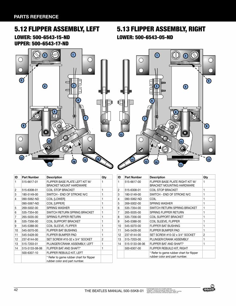
42
PARTS REFERENCE
THE BEATLES MANUAL 500-55K8-01© 2018 Apple Corps Ltd. All rights reserved. A Beatles™ product lecensed by Apple Corps Ltd. “Beatles” is a trademark of Apple Corps Ltd. “Apple” and the Apple logo are exclusively licensed by Apple Corps Ltd.
5.12 FLIPPER ASSEMBLY, LEFTLOWER: 500-6543-15-ND UPPER: 500-6543-17-ND
13
12
34
11
13
13
6
8
7
1014
5
9
5.13 FLIPPER ASSEMBLY, RIGHTLOWER: 500-6543-05-ND
1 2
3 4
11
13
6
8
7
1014
5
9
1212
1212
13
ID Part Number Description Qty1 515-6617-01 FLIPPER BASE PLATE LEFT KIT W/
BRACKET MOUNT HARDWARE1
2 515-6308-01 COIL STOP BRACKET 13 180-5149-00 SWITCH - END OF STROKE N/C 14 090-5062-ND COIL [LOWER] 1
090-5067-ND COIL [UPPER] 15 269-5002-00 SPRING WASHER 16 535-7354-00 SWITCH RETURN SPRING BRACKET 17 265-5035-00 SPRING FLIPPER RETURN 18 535-7356-00 COIL SUPPORT BRACKET 19 545-5388-00 COIL SLEEVE, FLIPPER 110 545-5070-00 FLIPPER BAT BUSHING 111 545-5428-00 FLIPPER BUMPER PAD 112 237-6144-00 SET SCREW #10-32 x 3/4" SOCKET 213 515-7203-01 PLUNGER/CRANK ASSEMBLY, LEFT 114 515-5133-08-06 FLIPPER BAT AND SHAFT* 1
500-6307-10 FLIPPER REBUILD KIT, LEFT* Refer to game rubber chart for flipper rubber color and part number.
ID Part Number Description Qty1 515-6617-00 FLIPPER BASE PLATE RIGHT KIT W/
BRACKET MOUNTING HARDWARE1
2 515-6308-01 COIL STOP BRACKET 13 180-5149-00 SWITCH - END OF STROKE N/C 14 090-5062-ND COIL 15 269-5002-00 SPRING WASHER 16 535-7354-00 SWITCH RETURN SPRING BRACKET 17 265-5035-00 SPRING FLIPPER RETURN 18 535-7356-00 COIL SUPPORT BRACKET 19 545-5388-00 COIL SLEEVE, FLIPPER 110 545-5070-00 FLIPPER BAT BUSHING 111 545-5428-00 FLIPPER BUMPER PAD 112 237-6144-00 SET SCREW #10-32 x 3/4" SOCKET 213 515-7203-00 PLUNGER/CRANK ASSEMBLY 114 515-5133-08-06 FLIPPER BAT AND SHAFT* 1
500-6307-00 FLIPPER REBUILD KIT, RIGHT* Refer to game rubber chart for flipper rubber color and part number.
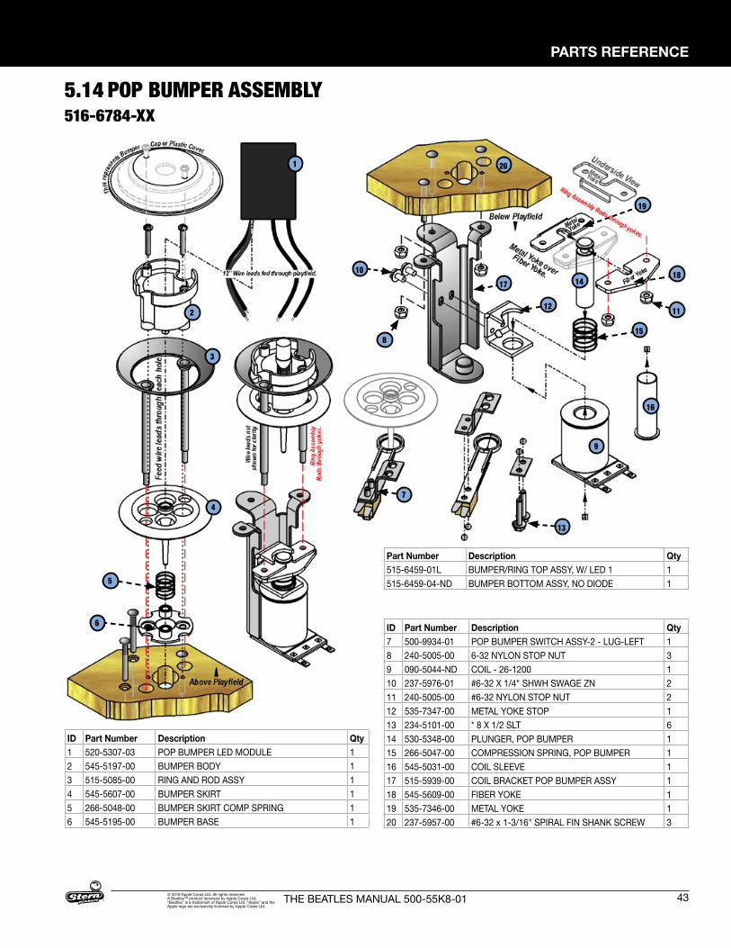
PARTS REFERENCE
43THE BEATLES MANUAL 500-55K8-01© 2018 Apple Corps Ltd. All rights reserved. A Beatles™ product lecensed by Apple Corps Ltd. “Beatles” is a trademark of Apple Corps Ltd. “Apple” and the Apple logo are exclusively licensed by Apple Corps Ltd.
5.14 POP BUMPER ASSEMBLY516-6784-XX
ID Part Number Description Qty1 520-5307-03 POP BUMPER LED MODULE 12 545-5197-00 BUMPER BODY 13 515-5085-00 RING AND ROD ASSY 14 545-5607-00 BUMPER SKIRT 15 266-5048-00 BUMPER SKIRT COMP SPRING 16 545-5195-00 BUMPER BASE 1
Part Number Description Qty515-6459-01L BUMPER/RING TOP ASSY, W/ LED 1 1515-6459-04-ND BUMPER BOTTOM ASSY, NO DIODE 1
ID Part Number Description Qty7 500-9934-01 POP BUMPER SWITCH ASSY-2 - LUG-LEFT 18 240-5005-00 6-32 NYLON STOP NUT 39 090-5044-ND COIL - 26-1200 110 237-5976-01 #6-32 X 1/4" SHWH SWAGE ZN 211 240-5005-00 #6-32 NYLON STOP NUT 212 535-7347-00 METAL YOKE STOP 113 234-5101-00 * 8 X 1/2 SLT 614 530-5348-00 PLUNGER, POP BUMPER 115 266-5047-00 COMPRESSION SPRING, POP BUMPER 116 545-5031-00 COIL SLEEVE 117 515-5939-00 COIL BRACKET POP BUMPER ASSY 118 545-5609-00 FIBER YOKE 119 535-7346-00 METAL YOKE 120 237-5957-00 #6-32 x 1-3/16" SPIRAL FIN SHANK SCREW 3
1
2
3
4
5
6
20
10
8
7
13
15
11
18
19
1417
12
9
16
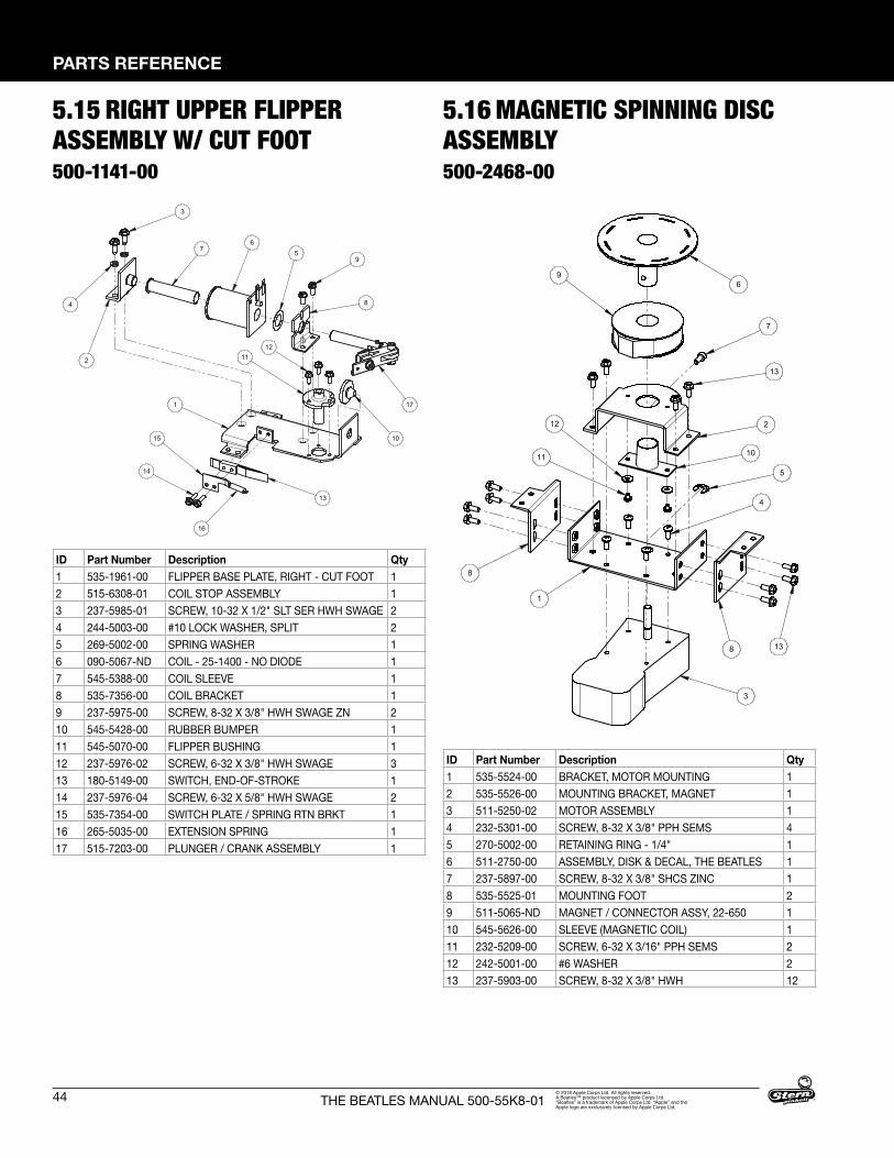
44
PARTS REFERENCE
THE BEATLES MANUAL 500-55K8-01© 2018 Apple Corps Ltd. All rights reserved. A Beatles™ product lecensed by Apple Corps Ltd. “Beatles” is a trademark of Apple Corps Ltd. “Apple” and the Apple logo are exclusively licensed by Apple Corps Ltd.
5.15 RIGHT UPPER FLIPPER ASSEMBLY W/ CUT FOOT500-1141-00
3
6
95
8
17
12
10
1
11
13
16
15
14
2
7
4
ITEM NO. PART NUMBER DESCRIPTION QTY.1 535-1961-00 FLIPPER BASE PLATE, RIGHT - CUT FOOT 12 515-6308-01 COIL STOP ASSEMBLY 13 237-5985-01 SCREW, 10-32 X 1/2" SLT SER HWH SWAGE 24 244-5003-00 #10 LOCK WASHER, SPLIT 25 269-5002-00 SPRING WASHER 16 090-5067-ND COIL - 25-1400 - NO DIODE 17 545-5388-00 COIL SLEEVE 18 535-7356-00 COIL BRACKET 19 237-5975-00 SCREW, 8-32 X 3/8" HWH SWAGE ZN 2
10 545-5428-00 RUBBER BUMPER 111 545-5070-00 FLIPPER BUSHING 112 237-5976-02 SCREW, 6-32 X 3/8" HWH SWAGE 313 180-5149-00 SWITCH, END-OF-STROKE 114 237-5976-04 SCREW, 6-32 X 5/8" HWH SWAGE 215 535-7354-00 SWITCH PLATE / SPRING RTN BRKT 116 265-5035-00 EXTENSION SPRING 117 515-7203-00 PLUNGER / CRANK ASSEMBLY 1
RIGHT FLIPPER ASSEMBLY W/ CUT FOOTTHE BEATLES
500-1141-00
ID Part Number Description Qty1 535-1961-00 FLIPPER BASE PLATE, RIGHT - CUT FOOT 12 515-6308-01 COIL STOP ASSEMBLY 13 237-5985-01 SCREW, 10-32 X 1/2" SLT SER HWH SWAGE 24 244-5003-00 #10 LOCK WASHER, SPLIT 25 269-5002-00 SPRING WASHER 16 090-5067-ND COIL - 25-1400 - NO DIODE 17 545-5388-00 COIL SLEEVE 18 535-7356-00 COIL BRACKET 19 237-5975-00 SCREW, 8-32 X 3/8" HWH SWAGE ZN 210 545-5428-00 RUBBER BUMPER 111 545-5070-00 FLIPPER BUSHING 112 237-5976-02 SCREW, 6-32 X 3/8" HWH SWAGE 313 180-5149-00 SWITCH, END-OF-STROKE 114 237-5976-04 SCREW, 6-32 X 5/8" HWH SWAGE 215 535-7354-00 SWITCH PLATE / SPRING RTN BRKT 116 265-5035-00 EXTENSION SPRING 117 515-7203-00 PLUNGER / CRANK ASSEMBLY 1
5.16 MAGNETIC SPINNING DISC ASSEMBLY500-2468-00
4
13
8
11
96
7
2
10
12
5
1
3
13
MAGNETIC SPINNING DISK ASSEMBLYTHE BEATLES
500-2468-00
8
ID Part Number Description Qty1 535-5524-00 BRACKET, MOTOR MOUNTING 12 535-5526-00 MOUNTING BRACKET, MAGNET 13 511-5250-02 MOTOR ASSEMBLY 14 232-5301-00 SCREW, 8-32 X 3/8" PPH SEMS 45 270-5002-00 RETAINING RING - 1/4" 16 511-2750-00 ASSEMBLY, DISK & DECAL, THE BEATLES 17 237-5897-00 SCREW, 8-32 X 3/8" SHCS ZINC 18 535-5525-01 MOUNTING FOOT 29 511-5065-ND MAGNET / CONNECTOR ASSY, 22-650 110 545-5626-00 SLEEVE (MAGNETIC COIL) 111 232-5209-00 SCREW, 6-32 X 3/16" PPH SEMS 212 242-5001-00 #6 WASHER 213 237-5903-00 SCREW, 8-32 X 3/8" HWH 12
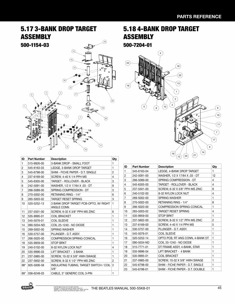
PARTS REFERENCE
45THE BEATLES MANUAL 500-55K8-01© 2018 Apple Corps Ltd. All rights reserved. A Beatles™ product lecensed by Apple Corps Ltd. “Beatles” is a trademark of Apple Corps Ltd. “Apple” and the Apple logo are exclusively licensed by Apple Corps Ltd.
5.17 3-BANK DROP TARGET ASSEMBLY500-1154-03
8
5
10
7
116
9
2
4
3
1
ITEM NO. PART NUMBER DESCRIPTION QTY.1 515-9926-00 3-BANK DROP - SMALL FOOT 12 545-6163-03 LEDGE, 3-BANK DROP TARGET 13 545-6798-00 SHIM - FICHE PAPER - D.T. SINGLE 24 237-6169-00 SCREW, 4-40 X 1/4 PPH MS 45 545-6305-00 TARGET - ROLLOVER - BLACK 36 242-5091-00 WASHER, 1/2 X 17/64 X .03 - DT 97 266-5089-00 SPRING COMPRESSION - DT 38 270-5002-00 RETAINING RING - 1/4" 69 265-5003-02 TARGET RESET SPRING 310 520-5252-13 3 BANK DROP TARGET PCB-OPTO, W/ RIGHT ANGLE CONN 111 237-5501-00 SCREW, 6-32 X 3/8" PPH MS ZINC 612 535-9995-01 COIL BRACKET 113 545-5076-01 COIL SLEEVE 114 090-5034-ND COIL 25-1240 - NO DIODE 115 269-5002-00 SPRING WASHER 116 530-5757-00 PLUNGER - D.T. ASSY. 117 266-5020-00 COMPRESSION SPRING-CONICAL 118 535-9959-00 STOP BRKT 119 240-5102-00 8-32 NYLON LOCK NUT 420 535-9996-03 LIFT BRACKET - 3 BANK 121 237-5985-00 SCREW, 10-32 X 3/8" HWH SWAGE 122 237-5602-00 SCREW, 8-32 X 1/2" PPH MS ZINC 298* 605-5006-58 INSULATING TUBING, TARGET SWITCH / COIL 5/8" 299* 036-6248-03 CABLE, 3" GENERIC COIL 3-PIN 1
18
22
20
21
12
19
13
15
14
16
17
3-BANK DROP TARGET ASSEMBLYTHE BEATLES
500-1154-03
ID Part Number Description Qty1 515-9926-00 3-BANK DROP - SMALL FOOT 12 545-6163-03 LEDGE, 3-BANK DROP TARGET 13 545-6798-00 SHIM - FICHE PAPER - D.T. SINGLE 24 237-6169-00 SCREW, 4-40 X 1/4 PPH MS 45 545-6305-00 TARGET - ROLLOVER - BLACK 36 242-5091-00 WASHER, 1/2 X 17/64 X .03 - DT 97 266-5089-00 SPRING COMPRESSION - DT 38 270-5002-00 RETAINING RING - 1/4" 69 265-5003-02 TARGET RESET SPRING 310 520-5252-13 3 BANK DROP TARGET PCB-OPTO, W/ RIGHT
ANGLE CONN1
11 237-5501-00 SCREW, 6-32 X 3/8" PPH MS ZINC 612 535-9995-01 COIL BRACKET 113 545-5076-01 COIL SLEEVE 114 090-5034-ND COIL 25-1240 - NO DIODE 115 269-5002-00 SPRING WASHER 116 530-5757-00 PLUNGER - D.T. ASSY. 117 266-5020-00 COMPRESSION SPRING-CONICAL 118 535-9959-00 STOP BRKT 119 240-5102-00 8-32 NYLON LOCK NUT 420 535-9996-03 LIFT BRACKET - 3 BANK 121 237-5985-00 SCREW, 10-32 X 3/8" HWH SWAGE 122 237-5602-00 SCREW, 8-32 X 1/2" PPH MS ZINC 298* 605-5006-58 INSULATING TUBING, TARGET SWITCH / COIL
5/8"2
99* 036-6248-03 CABLE, 3" GENERIC COIL 3-PIN 1
5.18 4-BANK DROP TARGET ASSEMBLY500-7204-01
5
16
18
4
3
2
8 10
1
13
22
23 6
11
17
1419
9
20
7
12
15
21
ITEM NO. PART NUMBER DESCRIPTION QTY.
1 545-6163-04 LEDGE, 4-BANK DROP TARGET 12 242-5091-00 WASHER, 1/2 X 17/64 X .03 - DT 123 266-5089-00 SPRING COMPRESSION - DT 44 545-6305-00 TARGET - ROLLOVER - BLACK 45 237-5501-00 SCREW, 6-32 X 3/8" PPH MS ZINC 86 240-5102-00 8-32 NYLON LOCK NUT 47 269-5002-00 SPRING WASHER 18 270-5002-00 RETAINING RING - 1/4" 89 266-5020-00 COMPRESSION SPRING-CONICAL 110 265-5003-02 TARGET RESET SPRING 411 535-9959-00 STOP BRKT 112 237-5602-00 SCREW, 8-32 X 1/2" PPH MS ZINC 213 237-6169-00 SCREW, 4-40 X 1/4 PPH MS 514 530-5757-00 PLUNGER - D.T. ASSY. 115 545-5076-01 COIL SLEEVE 116 520-5252-14 OPTO PCB, RT ANG CONN, 4-BANK DT 117 090-5034-ND COIL 25-1240 - NO DIODE 118 515-7771-01 DT FRAME ASSY, 4-BANK, STAR 119 535-9996-04 LIFT BRACKET - 4 BANK 120 535-9995-01 COIL BRACKET 121 237-5985-00 SCREW, 10-32 X 3/8" HWH SWAGE 122 545-6798-00 SHIM - FICHE PAPER - D.T. SINGLE 123 545-6798-01 SHIM - FICHE PAPER - D.T. DOUBLE 1
ID Part Number Description Qty1 545-6163-04 LEDGE, 4-BANK DROP TARGET 12 242-5091-00 WASHER, 1/2 X 17/64 X .03 - DT 123 266-5089-00 SPRING COMPRESSION - DT 44 545-6305-00 TARGET - ROLLOVER - BLACK 45 237-5501-00 SCREW, 6-32 X 3/8" PPH MS ZINC 86 240-5102-00 8-32 NYLON LOCK NUT 47 269-5002-00 SPRING WASHER 18 270-5002-00 RETAINING RING - 1/4" 89 266-5020-00 COMPRESSION SPRING-CONICAL 110 265-5003-02 TARGET RESET SPRING 411 535-9959-00 STOP BRKT 112 237-5602-00 SCREW, 8-32 X 1/2" PPH MS ZINC 213 237-6169-00 SCREW, 4-40 X 1/4 PPH MS 514 530-5757-00 PLUNGER - D.T. ASSY. 115 545-5076-01 COIL SLEEVE 116 520-5252-14 OPTO PCB, RT ANG CONN, 4-BANK DT 117 090-5034-ND COIL 25-1240 - NO DIODE 118 515-7771-01 DT FRAME ASSY, 4-BANK, STAR 119 535-9996-04 LIFT BRACKET - 4 BANK 120 535-9995-01 COIL BRACKET 121 237-5985-00 SCREW, 10-32 X 3/8" HWH SWAGE 122 545-6798-00 SHIM - FICHE PAPER - D.T. SINGLE 123 545-6798-01 SHIM - FICHE PAPER - D.T. DOUBLE 1
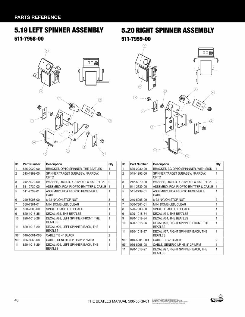
46
PARTS REFERENCE
THE BEATLES MANUAL 500-55K8-01© 2018 Apple Corps Ltd. All rights reserved. A Beatles™ product lecensed by Apple Corps Ltd. “Beatles” is a trademark of Apple Corps Ltd. “Apple” and the Apple logo are exclusively licensed by Apple Corps Ltd.
5.19 LEFT SPINNER ASSEMBLY511-7958-00
5.20 RIGHT SPINNER ASSEMBLY511-7959-00
ID Part Number Description Qty1 535-2029-00 BRACKET, OPTO SPINNER, THE BEATLES 12 515-1992-00 SPINNER TARGET SUBASSY: NARROW,
OPTO1
3 242-5079-00 WASHER, .150 I.D. X .312 O.D. X .050 THICK 24 511-2739-00 ASSEMBLY, PCA IR OPTO EMITTER & CABLE 15 511-2739-01 ASSEMBLY, PCA IR OPTO RECEIVER &
CABLE1
6 240-5005-00 6-32 NYLON STOP NUT 37 550-7361-01 MINI DOME-LED, CLEAR 18 520-7000-00 SINGLE FLASH LED BOARD 19 820-1018-35 DECAL #35, THE BEATLES 110 820-1018-28 DECAL #28, LEFT SPINNER FRONT, THE
BEATLES1
11 820-1018-29 DECAL #29, LEFT SPINNER BACK, THE BEATLES
1
98* 040-5001-00B CABLE TIE 4" BLACK 299* 036-8068-08 CABLE, GENERIC LP HS 8" 2P MFM 111 820-1018-29 DECAL #29, LEFT SPINNER BACK, THE
BEATLES1
ID Part Number Description Qty1 535-2030-00 BRACKET, BG OPTO SPINNNER, WITH SIGN 12 515-1992-00 SPINNER TARGET SUBASSY: NARROW,
OPTO1
3 242-5079-00 WASHER, .150 I.D. X .312 O.D. X .050 THICK 24 511-2739-00 ASSEMBLY, PCA IR OPTO EMITTER & CABLE 15 511-2739-01 ASSEMBLY, PCA IR OPTO RECEIVER &
CABLE1
6 240-5005-00 6-32 NYLON STOP NUT 37 550-7361-01 MINI DOME-LED, CLEAR 18 520-7000-00 SINGLE FLASH LED BOARD 19 820-1018-34 DECAL #34, THE BEATLES 19 820-1018-34 DECAL #34, THE BEATLES 110 820-1018-26 DECAL #26, RIGHT SPINNER FRONT, THE
BEATLES1
11 820-1018-27 DECAL #27, RIGHT SPINNER BACK, THE BEATLES
1
98* 040-5001-00B CABLE TIE 4" BLACK 299* 036-8068-08 CABLE, GENERIC LP HS 8" 2P MFM 111 820-1018-27 DECAL #27, RIGHT SPINNER BACK, THE
BEATLES1
78
6
5
1
3
2
4
11
ITEM NO. PART NUMBER DESCRIPTION QTY1 535-2029-00 BRACKET, OPTO SPINNER, PURPLE MARTIN 12 515-1992-00 SPINNER TARGET SUBASSY: NARROW, OPTO 13 242-5079-00 WASHER, .150 I.D. X .312 O.D. X .050 THICK 24 511-2739-00 ASSEMBLY, PCA IR OPTO EMITTER & CABLE 15 511-2739-01 ASSEMBLY, PCA IR OPTO RECEIVER & CABLE 16 240-5005-00 6-32 NYLON STOP NUT 37 550-7361-01 MINI DOME-LED, CLEAR 18 520-7000-00 SINGLE FLASH LED BOARD 19 820-1018-35 DECAL #35, PURPLE MARTIN 110 820-1018-28 DECAL #28, LEFT SPINNER FRONT, PURPLE MARTIN 111 820-1018-29 DECAL #29, LEFT SPINNER BACK, PURPLE MARTIN 198* 040-5001-00B CABLE TIE 4" BLACK 299* 036-8068-08 CABLE, GENERIC LP HS 8" 2P MFM 1
9
10
LEFT SPINNER ASSEMBLYTHE BEATLES
511-7958-00
7
8
4
11
1
5
3
6
2
ITEM NO. PART NUMBER DESCRIPTION QTY.1 535-2030-00 BRACKET, BG OPTO SPINNER, WITH SIGN 12 515-1992-00 SPINNER TARGET SUBASSY: NARROW, OPTO 13 242-5079-00 WASHER, .150 I.D. X .312 O.D. X .050 THICK 24 511-2739-00 ASSEMBLY, PCA IR OPTO EMITTER & CABLE 15 511-2739-01 ASSEMBLY, PCA IR OPTO RECEIVER & CABLE 16 240-5005-00 6-32 NYLON STOP NUT 37 550-7361-01 MINI DOME-LED, CLEAR 18 520-7000-00 SINGLE FLASH LED BOARD 19 820-1018-34 DECAL #34, PURPLE MARTIN 1
10 820-1018-26 DECAL #26, RIGHT SPINNER FRONT, PURPLE MARTIN 111 820-1018-27 DECAL #27, RIGHT SPINNER BACK, PURPLE MARTIN 198* 040-5001-00B CABLE TIE 4" BLACK 299* 036-8068-08 CABLE, GENERIC LP HS 8" 2P MFM 1
9
10
RIGHT SPINNER ASSEMBLYTHE BEATLES
511-7959-00
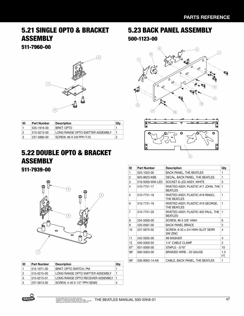
PARTS REFERENCE
47THE BEATLES MANUAL 500-55K8-01© 2018 Apple Corps Ltd. All rights reserved. A Beatles™ product lecensed by Apple Corps Ltd. “Beatles” is a trademark of Apple Corps Ltd. “Apple” and the Apple logo are exclusively licensed by Apple Corps Ltd.
5.21 SINGLE OPTO & BRACKET ASSEMBLY511-7960-00
5.22 DOUBLE OPTO & BRACKET ASSEMBLY511-7939-00
2
3
1
ITEM NO. PART NUMBER DESCRIPTION QTY.1 535-1916-00 BRKT: OPTO 12 515-0215-00 LONG RANGE OPTO EMITTER ASSEMBLY 13 237-5880-00 SCREW, #6 X 3/8 PPH T-25 2
SINGLE OPTO & BRACKET ASSEMBLYTHE BEATLES
511-7960-00
4
2
3
1
ITEM NO. PART NUMBER DESCRIPTION QTY.1 515-1971-00 BRKT: OPTO SWITCH, PM 12 515-0215-00 LONG RANGE OPTO EMITTER ASSEMBLY 13 515-0215-01 LONG RANGE OPTO RECEIVER ASSEMBLY 14 237-5813-00 SCREW, 4-40 X 1/2" PPH SEMS 4
DOUBLE OPTO & BRACKET ASSEMBLYTHE BEATLES
511-7960-00
ID Part Number Description Qty1 535-1916-00 BRKT: OPTO 12 515-0215-00 LONG RANGE OPTO EMITTER ASSEMBLY 13 237-5880-00 SCREW, #6 X 3/8 PPH T-25 2
ID Part Number Description Qty1 515-1971-00 BRKT: OPTO SWITCH, PM 12 515-0215-00 LONG RANGE OPTO EMITTER ASSEMBLY 13 515-0215-01 LONG RANGE OPTO RECEIVER ASSEMBLY 14 237-5813-00 SCREW, 4-40 X 1/2" PPH SEMS 4
9
16
45
7
310
12
8
8
11
ITEM NO. PART NUMBER DESCRIPTION QTY.1 525-1023-00 BACK PANEL, PURPLE MARTIN 12 820-8623-K8B DECAL, BACK PANEL, PURPLE MARTIN 13 519-5000-WW-LED SOCKET & LED ASSY, WHITE 54 510-7751-17 RIVETED ASSY, PLASTIC #17 JOHN, PURPLE MARTIN 15 510-7751-18 RIVETED ASSY, PLASTIC #18 RINGO, PURPLE MARTIN 16 510-7751-19 RIVETED ASSY, PLASTIC #19 GEORGE, PURPLE MARTIN 17 510-7751-20 RIVETED ASSY, PLASTIC #20 PAUL, PURPLE MARTIN 18 234-5000-00 SCREW, #6 X 3/8" HWH 69 535-0587-00 BACK PANEL BRACE 210 237-5975-02 SCREW, 8-32 x 3/4 HWH SLOT SERR SW ZINC 411 242-5005-00 #8 WASHER 412 040-5000-03 1/4" CABLE CLAMP 297* 631-5000-00 STAPLE - 5/16" 1098* 600-5003-00 BRAIDED WIRE - 20 GAUGE 1.5 FT.99* 036-8063-14-K8 CABLE, BACK PANEL, PURPLE MARTIN 1
2
BACK PANEL ASSEMBLYTHE BEATLES
500-1123-00
ID Part Number Description Qty1 525-1023-00 BACK PANEL, THE BEATLES 12 820-8623-K8B DECAL, BACK PANEL, THE BEATLES 13 519-5000-WW-LED SOCKET & LED ASSY, WHITE 54 510-7751-17 RIVETED ASSY, PLASTIC #17 JOHN, THE
BEATLES1
5 510-7751-18 RIVETED ASSY, PLASTIC #18 RINGO, THE BEATLES
1
6 510-7751-19 RIVETED ASSY, PLASTIC #19 GEORGE, THE BEATLES
1
7 510-7751-20 RIVETED ASSY, PLASTIC #20 PAUL, THE BEATLES
1
8 234-5000-00 SCREW, #6 X 3/8" HWH 69 535-0587-00 BACK PANEL BRACE 210 237-5975-02 SCREW, 8-32 x 3/4 HWH SLOT SERR
SW ZINC4
11 242-5005-00 #8 WASHER 412 040-5000-03 1/4" CABLE CLAMP 297* 631-5000-00 STAPLE - 5/16" 1098* 600-5003-00 BRAIDED WIRE - 20 GAUGE 1.5
FT.99* 036-8063-14-K8 CABLE, BACK PANEL, THE BEATLES 1
5.23 BACK PANEL ASSEMBLY500-1123-00
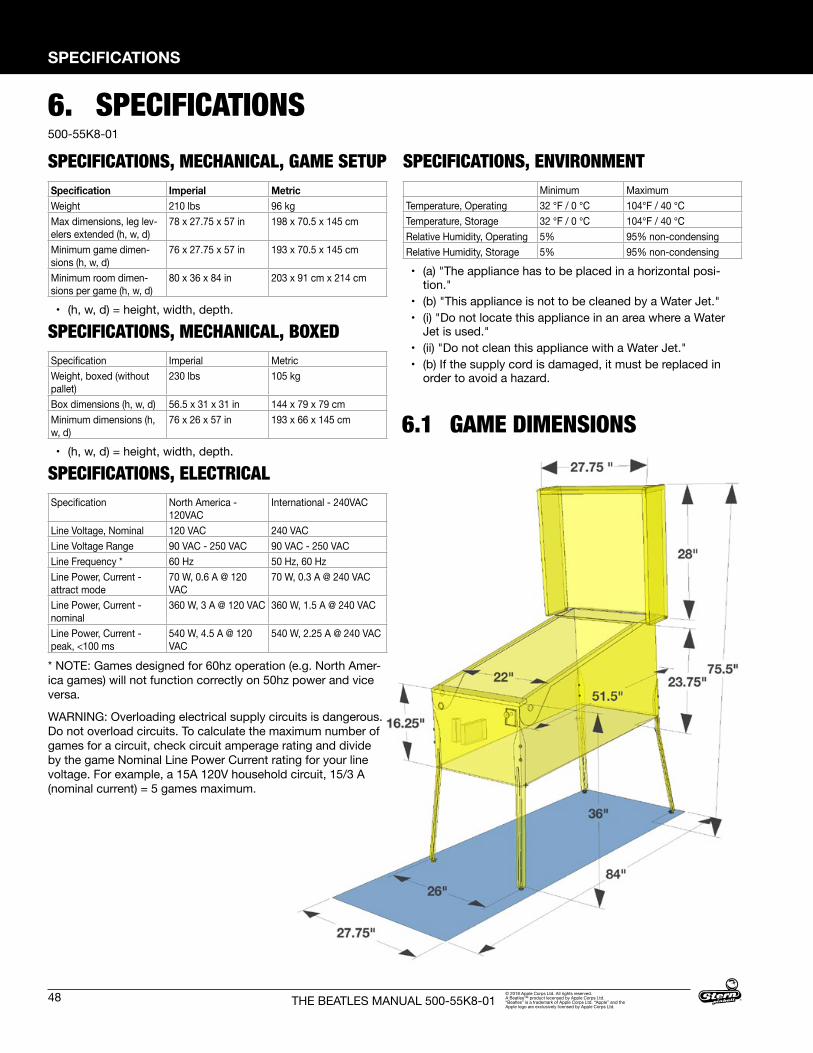
48
SPECIFICATIONS
THE BEATLES MANUAL 500-55K8-01© 2018 Apple Corps Ltd. All rights reserved. A Beatles™ product lecensed by Apple Corps Ltd. “Beatles” is a trademark of Apple Corps Ltd. “Apple” and the Apple logo are exclusively licensed by Apple Corps Ltd.
6.1 GAME DIMENSIONS
6. SPECIFICATIONS500-55K8-01
SPECIFICATIONS, MECHANICAL, GAME SETUPSpecification Imperial MetricWeight 210 lbs 96 kgMax dimensions, leg lev-elers extended (h, w, d)
78 x 27.75 x 57 in 198 x 70.5 x 145 cm
Minimum game dimen-sions (h, w, d)
76 x 27.75 x 57 in 193 x 70.5 x 145 cm
Minimum room dimen-sions per game (h, w, d)
80 x 36 x 84 in 203 x 91 cm x 214 cm
• (h, w, d) = height, width, depth.
SPECIFICATIONS, MECHANICAL, BOXEDSpecification Imperial MetricWeight, boxed (without pallet)
230 lbs 105 kg
Box dimensions (h, w, d) 56.5 x 31 x 31 in 144 x 79 x 79 cmMinimum dimensions (h, w, d)
76 x 26 x 57 in 193 x 66 x 145 cm
• (h, w, d) = height, width, depth.
SPECIFICATIONS, ELECTRICAL Specification North America -
120VACInternational - 240VAC
Line Voltage, Nominal 120 VAC 240 VACLine Voltage Range 90 VAC - 250 VAC 90 VAC - 250 VACLine Frequency * 60 Hz 50 Hz, 60 HzLine Power, Current - attract mode
70 W, 0.6 A @ 120 VAC
70 W, 0.3 A @ 240 VAC
Line Power, Current - nominal
360 W, 3 A @ 120 VAC 360 W, 1.5 A @ 240 VAC
Line Power, Current - peak, <100 ms
540 W, 4.5 A @ 120 VAC
540 W, 2.25 A @ 240 VAC
* NOTE: Games designed for 60hz operation (e.g. North Amer-ica games) will not function correctly on 50hz power and vice versa.
WARNING: Overloading electrical supply circuits is dangerous. Do not overload circuits. To calculate the maximum number of games for a circuit, check circuit amperage rating and divide by the game Nominal Line Power Current rating for your line voltage. For example, a 15A 120V household circuit, 15/3 A (nominal current) = 5 games maximum.
SPECIFICATIONS, ENVIRONMENTMinimum Maximum
Temperature, Operating 32 ℉ / 0 ℃ 104℉ / 40 ℃ Temperature, Storage 32 ℉ / 0 ℃ 104℉ / 40 ℃ Relative Humidity, Operating 5% 95% non-condensingRelative Humidity, Storage 5% 95% non-condensing
• (a) "The appliance has to be placed in a horizontal posi-tion."
• (b) "This appliance is not to be cleaned by a Water Jet."• (i) "Do not locate this appliance in an area where a Water
Jet is used."• (ii) "Do not clean this appliance with a Water Jet."• (b) If the supply cord is damaged, it must be replaced in
order to avoid a hazard.

SPECIFICATIONS
49THE BEATLES MANUAL 500-55K8-01© 2018 Apple Corps Ltd. All rights reserved. A Beatles™ product lecensed by Apple Corps Ltd. “Beatles” is a trademark of Apple Corps Ltd. “Apple” and the Apple logo are exclusively licensed by Apple Corps Ltd.
820-6617-00
ATTENTION!IMPORTANT WARRANTY INFORMATION
The electronics system, node network architecture, mechanical devices and associated software control systems in this pinball machine are designed to work with genuine Stern Pinball accessories and devices.
Installation of non-authorized accessories, lamps, LED’s, motors or other devices or modification of electro-mechanical devices may damage the system and will void your warranty.
6.2 WARRANTY500-55K8-01Stern Pinball machines are assembled in Elk Grove Village, Illinois, USA; each pinball machine has unique characteristics that make it a one-of-a-kind American-made product. Each machine will have variations in appearance resulting from differences in the machine’s particular wood parts, individual silk screened art and mechanical assemblies. Stern Pinball has inspected each game element to insure it meets stringent quality and playability standards.
STERN PINBALL INC LIMITED WARRANTYStern Pinball Inc (‘SELLER’) warrants only to the initial purchaser of its products that the items listed below are free from defects in material and workmanship under normal use and service for the warranty period specified:
• Printed circuit boards (game logic): 2 months• Dot Matrix / LCD Display: 9 months
No other parts of seller’s product are warranted.
Warranty periods are effective from the initial date of shipment from seller to its authorized distributors.
Seller’s sole liability shall be, at its option, to repair or replace products which are returned to seller during the warranty periods specified, provided:
1. Seller is notified promptly upon discovery by purchaser that stated products are defective.
2. Such products are properly packaged and then returned freight prepaid, to seller’s plant.
This warranty does not apply to any parts damaged during shipment and/or due to improper handling, or due to improper installation or usage, or alteration. In no event shall the seller be liable for any anticipated profits, loss of profits, loss of use, accidental or consequential damages, or any other losses incurred by the customer in connection with the purchase of a Stern Pinball Inc Product.
WARRANTY DISCLAIMERExcept as specifically provided in a written contract between seller and purchaser, there are no other warranties, express or implied, including any implied warranties of merchantability or fitness for a particular purpose.
This Game Service Manual and all other documents relating to this product, playfield components, features, rules, programming, and operation are subject to change without notice (Service Bulletins, if applicable, available through official Stern Pinball website).
6.3 WARNINGS, COMPLIANCE, AND LEGAL NOTICESPHOTOSENSITIVE SEIZURES HEALTH WARNING
A very small percentage of people may experience a seizure when exposed to certain visual images, including flashing lights or patterns. Even people with no history of seizures of epilepsy may have an undiagnosed condition that can cause “photosensitive epileptic seizures” due to certain visual
images, flashing lights or patterns. Symptoms can include lightheadedness, altered vision, eye or face twitching, jerking or shaking of arms or legs, disorientation, confusion, momentary loss of awareness, and loss of consciousness or convulsions that can lead to injury from falling down or striking nearby objects.
IMMEDIATELY STOP PLAYING AND CONSULT A DOCTOR IF YOU EXPERIENCE ANY OF THESE SYMPTOMS.
PARTS SUBSTITUTIONSFor safety and reliability, substitute parts and equipment modifications are not recommended and may void any and all warranties. Use of Non-Stern Pinball Inc Parts or Modifications of game circuitry may adversely affect game play or game safety. Transport pinball machines with hinged backbox in the down position only! Always take great care
when servicing any game. Always ready the service manual before replacing or servicing components. Substitutions of parts or equipment modifications may void FCC type acceptance.
Always disconnect the line voltage before servicing. Some parts may remain energized when unplugged. Take great caution when servicing any electrical components.
FCC CLASS A SUBPART J COMPLIANCEThis equipment has been tested and found to comply with the limits for a Class A digital device, pursuant to part 15 of the FCC Rules. These limits are designed to provide reasonable protection against harmful interference when the equipment is operated in a commercial environment. This equipment generates,
uses, and can radiate radio frequency energy and, if not installed and used in accordance with the instruction manual, may cause harmful interference to radio communications. Operation of this equipment in a residential area is likely to cause harmful interference in which case the user will be required to correct the interference at his own expense.
RF INTERFERENCE NOTICEThe cable harness placements, ground strap routing, and other shielding have been designed to keep RF radiation and conduction within levels accepted by FCC rules. To maintain these levels, factory harness position, shielding, and ground straps must be installed in their factory locations should they become disconnected during maintenance.
COPYRIGHT AND INTELLECTUAL PROPERTY NOTICEThis document and the data disclosed herein or herewith is not to be reproduced (Except where noted), used, or otherwise disclosed in whole or in part to anyone without written consent of Stern Pinball Inc.
Products in this manual, the company name and devices and the design of the manual itself are protected by federal patents (and patents pending), design registrations, trademarks, and copyrights. Action will be taken in the event of infringement or imitation. The right is reserved to change specifications without prior notice.

[email protected] WWW.STERNPINBALL.COM FACEBOOK.COM/STERNPINBALL
THE BEATLES GOLD #500-55K8-01 THE BEATLES PLATINUM #500-55K7-01 THE BEATLES DIAMOND #500-55K9-01
MANUAL #780-50K8-00
*780-50K8-00*