K76 Cadillac Plus Owner Manual
7
K76-LND7317/GPS Cadillac+plus Geiger Counter by Atomic.dave [email protected] This is a one of a kind custom hand-made Geiger Counter built by Atomic.Dave. It is based on a kit de- signed by John Giametti (username: Brohogan) I have been building his DIY Geiger counters for over a year and a half having built and sold around 80 of them. All inf ormation for this kit is availab le at the developer’s website. As I have said before, this is more of a kit for someone who knows a little bit about electronics but doesn’t have the time or patience to build it, or would rather someone else do all the dirty work. Having been built by me, of course there will be some imperfections, although as minimal as possible. The first one like this took close to a year to complete. It is one of the most advanced kit of all that I have created, with most of the features available. OPERATION 1. LCD DISPLAY : Push the large yellow button to turn on the unit. The LCD backlight display light comes on, and you will see the words: Atomic.Dave K76 CADILLAC+plus This customized first welcome window can easily be changed if you want, by doing a little programming in Arduino. Refer to the DIY site for directions at the SOFTWARE section. The second window will show this: 345 CPM = 1 uSv Running at 5.05V The first line refers to the conversion rate of CPM to uSv/hr for your LND7317 tube (345) this can be changed either in the program sketch, with Arduino, or with the Sony wireless remote control which I will ex- plain later. The second line refers to the current voltage that your system is running at. This is a 5 volt sys- tem. The 3000mAh 3.7v lipo battery is boosted to 5v with a pololu booster. Everytime you start up your GC (geiger counter) it will show you this so you will always know your current voltage. The third window will look something like this: Log file: GPSLOG17.csv This is the confirmation that the SD card is inser ted in and it is currently available for writing data logs. The number is the log number . Y ou can set how manytimes per minute or per hour you can write to the card automatcally . There is also a button just above the Backlight switch on the top left that is used to write what- ever data is on the s creen to the SD card. Inf ormation such as CPM, uSv/hr, battery votage, GPS coordi- nates, date and time are recorded. If the SD card is not inserted you will get an error message like this: CARD! On the first line is the current CPM and its corresponding uSv/hr to the r ight of it. The second line is the default date and time which will always be this when you start up as the GPS has not synced with a satellite yet. (sign ified by a solid red LED at the very top of the GC) Once the GPS syncs, the LED will blink, and the date and time will update to the current one. Howev er, you will hav e to make sure your time zone is right (which can be adjusted in the sketch, or with the remote) the clock is a 24 hour clock. Once the GPS syncs, the display will alternate between date/time and speed/altitude. CPM 24 0.07 11/21/12 22:36 2. LEDS: Right away , you will hear the beeping of the piezo as your LND7317 GM tube picks up radiation events. There are two LEDs below the LCD. The right one is RED for the Alarm which will only light up when a set alarm threshold is reached. The piezo for the alarm has a mute switch allowing you to have a LED only silient alarm. The left LED is BLUE which is for radiation events and coincides with the beeping piezo which can be muted with the mute switch. 3. SWITCHES, SLOTS, LEDS, BUTTONS, PORTS, DIALS: A. Starting on the left topside of the GC is the LCD contrast dial used for controlling the contrast of the LCD from time to time it may or may not need to adjusted with a small screwdriver. B. Next is the SD Card slot. Please take special care when inserting and removing the card. Once you have it in the slot, with the very tip of your thumb, push the SD card into the slot until you feel it click into place. Use the same positition of the Thumb to release it. Once you take out the SD Card, use the included SD card adapter and plug it into your mac or PC. There will be a .csv file that is compatible with Microsoft excel. Open the file with Excel, and you will see all the information listed. T he button on top marked SDLOG is used to write to the card. Push it, and the display will say LOGGED! C. INPUT Next down, left side, is the Mini USB FTDI port for programming in Arduino. Wh en uploading any new changes to the program sketch, you will need to turn off the GPS in order to do that as they share the same serial por t. The Switch for the GPS is located on the face on the far right. Once the edited sketch is uploaded you can turn the GPS back on.
-
Upload
david-kasai -
Category
Documents
-
view
224 -
download
0
Transcript of K76 Cadillac Plus Owner Manual
8/13/2019 K76 Cadillac Plus Owner Manual
http://slidepdf.com/reader/full/k76-cadillac-plus-owner-manual 1/7
K76-LND7317/GPS Cadillac+plus Geiger Counterby Atomic.dave [email protected]
This is a one of a kind custom hand-made Geiger Counter built by Atomic.Dave. It is based on a kit de-
igned by John Giametti (username: Brohogan) I have been building his DIY Geiger counters for over a year
nd a half having built and sold around 80 of them. All information for this kit is available at the developer’s
website. As I have said before, this is more of a kit for someone who knows a little bit about electronics but
oesn’t have the time or patience to build it, or would rather someone else do all the dirty work. Having been
uilt by me, of course there will be some imperfections, although as minimal as possible. The first one like
his took close to a year to complete. It is one of the most advanced kit of all that I have created, with most of
he features available.
OPERATION
. LCD DISPLAY: Push the large yellow button to turn on the unit. The LCD backlight display light comes on,
nd you will see the words:
Atomic.Dave K76
CADILLAC+plus
This customized first welcome window can easily be changed if you want, by doing a little programming
n Arduino. Refer to the DIY site for directions at the SOFTWARE section.
The second window will show this:
345 CPM = 1 uSv
Running at 5.05V
The first line refers to the conversion rate of CPM to uSv/hr for your LND7317 tube (345) this can be
hanged either in the program sketch, with Arduino, or with the Sony wireless remote control which I will ex-
lain later. The second line refers to the current voltage that your system is running at. This is a 5 volt sys-
em. The 3000mAh 3.7v lipo battery is boosted to 5v with a pololu booster. Everytime you start up your GCgeiger counter) it will show you this so you will always know your current voltage.
The third window will look something like this:
Log file:
GPSLOG17.csv
This is the confirmation that the SD card is inserted in and it is currently available for writing data logs.
The number is the log number. You can set how manytimes per minute or per hour you can write to the card
utomatcally. There is also a button just above the Backlight switch on the top left that is used to write what-
ver data is on the screen to the SD card. Information such as CPM, uSv/hr, battery votage, GPS coordi-
ates, date and time are recorded. If the SD card is not inserted you will get an error message like this:
CARD!
On the first line is the current CPM and its corresponding uSv/hr to the right of it. The second line is the
efault date and time which will always be this when you start up as the GPS has not synced with a satellite
et. (signified by a solid red LED at the very top of the GC) Once the GPS syncs, the LED will blink, and the
ate and time will update to the current one. However, you will have to make sure your time zone is rightwhich can be adjusted in the sketch, or with the remote) the clock is a 24 hour clock. Once the GPS syncs,
he display will alternate between date/time and speed/altitude.
CPM 24 0.07
11/21/12 22:36
2. LEDS: Right away, you will hear the beeping of the piezo as your LND7317 GM tube picks up radiation
vents. There are two LEDs below the LCD. The right one is RED for the Alarm which will only light up when
set alarm threshold is reached. The piezo for the alarm has a mute switch allowing you to have a LED only
ilient alarm. The left LED is BLUE which is for radiation
vents and coincides with the beeping piezo which can
e muted with the mute switch.
3. SWITCHES, SLOTS, LEDS, BUTTONS, PORTS,
DIALS:
A. Starting on the left topside of the GC is the LCDontrast dial used for controlling the contrast of the LCD
rom time to time it may or may not need to adjusted
with a small screwdriver.
B. Next is the SD Card slot. Please take special
are when inserting and removing the card. Once you
ave it in the slot, with the very tip of your thumb, push the SD card into the slot until you feel it click into
lace. Use the same positition of the Thumb to release it. Once you take out the SD Card, use the included
SD card adapter and plug it into your mac or PC. There will be a .csv file that is compatible with Microsoft
xcel. Open the file with Excel, and you will see all the information listed. The button on top marked SDLOG
s used to write to the card. Push it, and the display will say LOGGED!
C. INPUT Next down, left side, is the Mini USB FTDI port for programming in Arduino. When uploading
ny new changes to the program sketch, you will need to turn off the GPS in order to do that as they share
he same serial por t. The Switch for the GPS is located on the face on the far right. Once the edited sketch is
ploaded you can turn the GPS back on.
8/13/2019 K76 Cadillac Plus Owner Manual
http://slidepdf.com/reader/full/k76-cadillac-plus-owner-manual 2/7
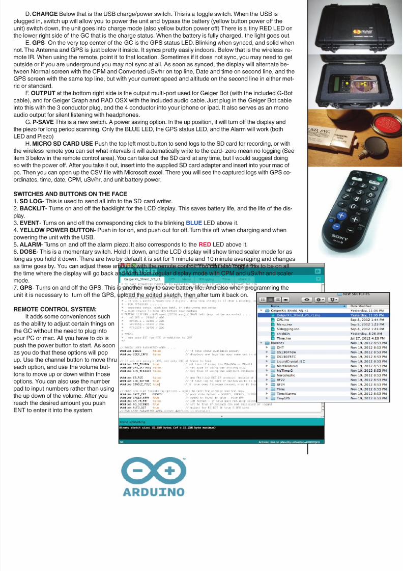
D. CHARGE Below that is the USB charge/power switch. This is a toggle switch. When the USB is
lugged in, switch up will allow you to power the unit and bypass the battery (yellow button power off the
nit) switch down, the unit goes into charge mode (also yellow button power off) There is a tiny RED LED on
he lower right side of the GC that is the charge status. When the battery is fully charged, the light goes out.
E. GPS- On the very top center of the GC is the GPS status LED. Blinking when synced, and solid when
ot. The Antenna and GPS is just below it inside. It syncs pretty easily indoors. Below that is the wireless re-
mote IR. When using the remote, point it to that location. Sometimes if it does not sync, you may need to get
utside or if you are underground you may not sync at all. As soon as synced, the display will alternate be-
ween Normal screen with the CPM and Converted uSv/hr on top line, Date and time on second line, and the
GPS screen with the same top line, but with your current speed and altitude on the second line in either met-
c or standard.
F. OUTPUT at the bottom right side is the output multi-port used for Geiger Bot (with the included G-Bot
able), and for Geiger Graph and RAD OSX with the included audio cable. Just plug in the Geiger Bot cablento this with the 3 conductor plug, and the 4 conductor into your iphone or ipad. It also serves as an mono
udio output for silent listening with headphones.
G. P-SAVE This is a new switch. A power saving option. In the up position, it will turn off the display and
he piezo for long period scanning. Only the BLUE LED, the GPS status LED, and the Alarm will work (both
ED and Piezo)
H. MICRO SD CARD USE Push the top left most button to send logs to the SD card for recording, or with
he wireless remote you can set what intervals it will automatically write to the card- zero mean no logging (See
em 3 below in the remote control area). You can take out the SD card at any time, but I would suggest doing
o with the power off. After you take it out, insert into the supplied SD card adapter and insert into your mac of
c. Then you can open up the CSV file with Microsoft excel. There you will see the captured logs with GPS co-
rdinates, time, date, CPM, uSv/hr, and unit battery power.
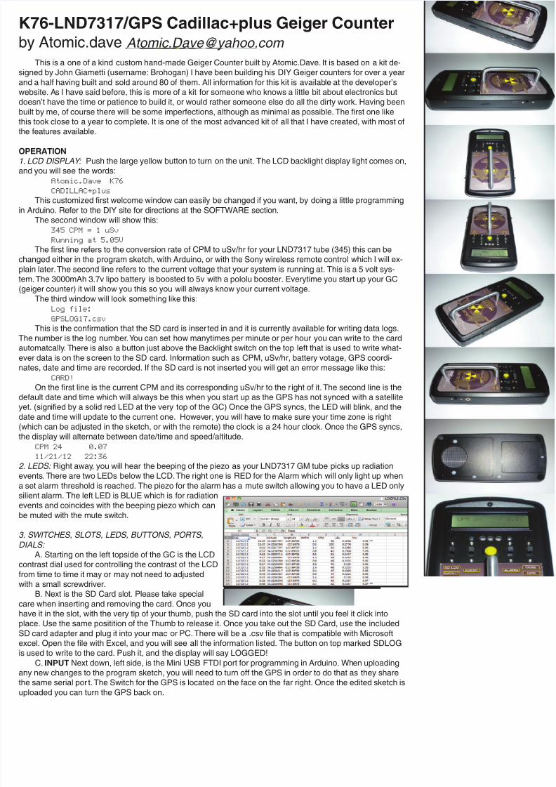
SWITCHES AND BUTTONS ON THE FACE
. SD LOG- This is used to send all info to the SD card writer.
. BACKLIT- Turns on and off the backlight for the LCD display. This saves battery life, and the life of the dis-
lay.
. EVENT- Turns on and off the corresponding click to the blinking BLUE LED above it.
. YELLOW POWER BUTTON- Push in for on, and push out for off. Turn this off when charging and when
owering the unit with the USB.
. ALARM- Turns on and off the alarm piezo. It also corresponds to the RED LED above it.
. DOSE- This is a momentary switch. Hold it down, and the LCD display will show timed scaler mode for as
ong as you hold it down. There are two by default it is set for 1 minute and 10 minute averaging and changes
s time goes by. You can adjust these amounts with the remote control. You can also toggle this to be on all
he time where the display will go back and forth from regular display mode with CPM and uSv/hr and scaler
mode.
. GPS- Turns on and off the GPS. This is another way to save battery life. And also when programming the
nit it is necessary to turn off the GPS, upload the edited sketch, then after turn it back on.
REMOTE CONTROL SYSTEM:
It adds some conveniences such
s the ability to adjust certain things on
he GC without the need to plug into
our PC or mac. All you have to do is
ush the power button to start. As soon
s you do that these options will pop
p. Use the channel button to move thru
ach option, and use the volume but-
ons to move up or down within those
ptions. You can also use the number
ad to input numbers rather than using
he up down of the volume. After you
each the desired amount you push
ENT to enter it into the system.
8/13/2019 K76 Cadillac Plus Owner Manual
http://slidepdf.com/reader/full/k76-cadillac-plus-owner-manual 3/7
. SEC DISP PERIOD is the number of seconds before the display refreshes. (5 seconds is a good setting. Display is now based on a "runni
verage" like the Geiger Kit.)
. 1= DOSE MODE ON - Dose Mode shows the running average of CPM & uSv/h on an alternate display that comes up after 4 display perio
ave passed. It can also be activated by closing DIP switch #1 on the board. Note that Dose Mode will only begin to display once 1 minute ha
assed.
. MIN LOGGING is when to write the log data to the MicroSD card (in minutes). Zero means no log. (Since the setting is in minutes, logged
ults will not be subject to rounding errors.)
. CPM->uSv RATIO is ratio for the type of GM tube used. 175 is the default for the SBM-20 and 100 is for the LDN712. 334 for LND7317. Unli
he "default sketch" only one ratio is supported, but now it can be easily changed. Just type in the number, and push ENT to confirm.
. ALARM > CPM when the CPM is greater than this value the alarm LED and Piezo will go off. (or only the LED when the alarm piezo is tur
ff)
. ZONE (>12= +) you need to set your time zone because the GPS provides time in UTC format. The time zone can be anything between -1
nd +12, but avoid the complexities of entering negative numbers, values between 0 and 12 are considered negative, and above 12, positiveyour zone is +5 you would set 17.
for some odd reason the remote does not work, hit the mute button and when the IR OK! shows up on the display, you are synced, hit the
ower button then start hitting the up down on the channel button. Other options can also be added if you know how to program in Arduino.
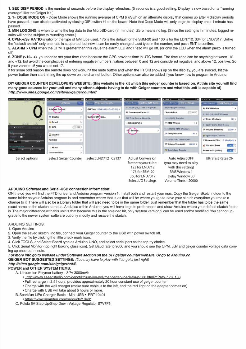
DIY GEIGER COUNTER DEVELOPERS WEBSITE: (this website is the kit which this geiger counter is based on. At this site you will
many good sources for your unit and many other subjects having to do with Geiger counters and what this unit is capable of)
http://www.sites.google.com/site/diygeigercounter/
ARDUINO Software and Serial-USB connection information:
ON the cd you will find the FTDI driver and Arduino program version 1. Install both and restart your mac. Copy the Geiger Sketch folder to the
ame folder as your Arduino program is and remember where that is as that will be where you go to save your sketch everytime you make a
hange to it. There will also be a Library folder that will also need to be in the same folder. Just remember that the folder has to be the same
xact name as the sketch name is. And also within Arduino, you will have to go to preferences and show Arduino where your default sketch f
s. The major difference with this unit is that because this is the shielded kit, only system version 9 can be used and/or modified. You cannot u
rade to the newer system software but only modify and resave the sketch.
ARDUINO SETTINGS:
. Open Arduino
. Open the saved sketch .ino file, connect your Geiger counter to the USB with power switch off.
. Verify the file by clicking the little check mark icon.
. Click TOOLS, and Select Board type as Arduino UNO, and select serial port as the top tty choice.
. Click Serial Monitor (top right looking glass icon). Set Baud rate to 9600 and you should see the CPM, uSv and geiger counter voltage data c
ng up once per minute.
For more info go to website under Software section on the DIY geiger counter website. Or go to Arduino.cc
GEIGER BOT SUGGESTED SETTINGS: (You may have to play with it to get it just right)
http://sites.google.com/site/geigerbot/S
POWER and OTHER SYSTEM ITEMS:
A. Lithium Ion Polymer battery - 3.7v 3000mAh
• http://www.seeedstudio.com/depot/lithium-ion-polymer-battery-pack-3a-p-588.html?cPath=178_183
• Full recharge in 2.5 hours, provides approximately 20 hour constant use of geiger counter
• Charge with the wall charger (make sure cable is to the left, and the red light on the adapter comes on)
• Charge with USB will take about 5 hours or more.
B. Sparkfun LiPo Charger Basic - Mini-USB • PRT-10401
• https://www.sparkfun.com/products/10401
C. Pololu 5V Step-Up/Step-Down Voltage Regulator S7V7F5
Select options Select Geiger Counter Select LND712 CS137 Adjust Conversion
factor to your tube:
123 for LND712
175 for SBM-20
360 for LND7317
Select I/O Settings
Auto Adjust OFF
(you may need to play
with this setting)
RMS Window 1
Delay Window 30
Volume Thresh 20000
Ultrafast Rates O

8/13/2019 K76 Cadillac Plus Owner Manual
http://slidepdf.com/reader/full/k76-cadillac-plus-owner-manual 4/7
• http://www.pololu.com/catalog/product/2119
D. Sparkfun 5V FTDI Basic Breakout
• https://www.sparkfun.com/products/9716
E. Adafruit EM-406A GPS Module
• http://www.adafruit.com/products/99
ND-7317 GEIGER MULLER TUBE
nstalled inside this nicely planned out kit is a PANCAKE LND 7317 which senses Alpha, Beta and Gamma.
The pancake tube is mounted to the case by a solid copper bracket, with a galvanized 1/8" mesh for protec-
on and silicon feet. It has a handle that was placed in a well balanced position. I will be Including and ship-
ing the Geiger Counter inside a Pelican 1150 atmospheric controlled case to protect the pancake from high
ltitude and pressure implosion during shipping.
ttp://www.lndinc.com/products/17/
ENCLOSURE
Dimensions: New Age Enclosure - S784114 - 7.8" x 4.1" x 1.4" (not including handle or feet)
ttp://www.newageenclosures.com/files/784114_r5_2.pdf
CARRYING CASE
ttp://www.pelican-case.com/1150.html
REPAIRS:
There is a very exact order to opening and closing the case, that I can explain to you if you need to but I would
ot suggest it. I will be more than happy to do any maintenance if you need at no charge except shipping.
PACKAGE CONTENTS:n your package you will find: Cadillac+Plus Geiger Counter, Pelican 1150 Case, Lead Pig w/ Samples, Sony
RM-EZ4 Remote Control, SanDisk 8GB Micro SD disk and Adapter, (3) Cables: Geiger bot 3 to 4 conductor,
Audio 3 to 3 conductor, Mini USB to standard USB2. (2) Chargers: Cigarette adapter & 5V white wall
harger. CD with software and documents, Manual, stickers, and extra faceplate labels.

8/13/2019 K76 Cadillac Plus Owner Manual
http://slidepdf.com/reader/full/k76-cadillac-plus-owner-manual 5/7

8/13/2019 K76 Cadillac Plus Owner Manual
http://slidepdf.com/reader/full/k76-cadillac-plus-owner-manual 6/7
a t o m i c . d a v e
R A D I A T I O N
D E T E C T O R
ALP HA B
E T
A
G A M M
A
X - R A Y
A L A R M
E
V E N T
B A C K L T
S D L O G
D O S E
I N P U T
C H A R G E
O U T P U T
P - S A V E
G P S
C A D I L L A C + p l u s
L N D
7 3 1 7

8/13/2019 K76 Cadillac Plus Owner Manual
http://slidepdf.com/reader/full/k76-cadillac-plus-owner-manual 7/7
8
7
6
4
3
2
5
+ –
+
–
1 4
1 7
1 8
1 9
1 6
1 5
1 2
2 6
1 2 3
1 2 3
1 2 3
B A C K L I G H T
B
S O U N D
C
A L A R M
D
P O
W E R
E
F
+
_
E V E N T
L E D
A L A R M
L E D
I n
L R
O u t
2 4 6
3
D O S E
1 2 3
G P S
P O W E R S A V E
W R I T E
C H A R G E
A
G
H
I
1
2
1
2
1 0
1 1
5 V U p / D o w n
B O O S T
L I P O
C H
A R G E R
A L A R M
P I E Z O
1 K O H M
R E S I S T O R
5 6 K O H M
R E S I S T O R
3 . 5 m m
S o c k e t
M U L T I - P O R T . 1
u F
C
a p
. 1 u F
C a p
2 7 0 O H M
R E S I S T O R
3 0 0 O H M
R E S I S T O R
1 3
1 5
4
5 1
9
L I P O
F T D I
1 2 3 4
I R S E N
S O R
3
G P S
L C D
C O N T R
A S T
P O T
A L A R M
E V E N T
B A C K L T
S D L O G
D O S E
G P S
A
I
B
G
C
D
F
H
E
a t o m i c . d a v e
R A D I A T I O N
D E T E C T O R
ALP HA B
E T
A
G A M M A
X - R A Y
A L A R M
E V E N T
B A C K L T
S D L O G
D O S E
I N P U T
C H A R G E
O U T P U T
P - S A V E
G P S
C A D I L L A C + p l u s
L N D 7 3 1 7
1 . G N D
2 . V C C
3 . R X
4 . T X
5 . G N D
6 . N / C
G N D
V C C
R X
T X
G N D
N / C
P i n # 1 i s o n
t h e R I G H T
6 5 4 3 2 1
+ –