K2 System Guide v9.2 - Grass Valley
278
Media Platform K2 System Guide Software Version 9.2 071-8726- 05 2014 01 31
Transcript of K2 System Guide v9.2 - Grass Valley

Media PlatformK2
System GuideSoftware Version 9.2
071-8726- 052014 01 31


Media Platform
K2
System GuideSoftware Version 9.2
071-8726- 052014 01 31


Contents
Safety Summaries......................................................................................................................................11
Preface.......................................................................................................................................................23
Product description.....................................................................................................................................29About K2 systems...................................................................................................................................29K2 Summit 3G system features..............................................................................................................29K2 Summit system features....................................................................................................................30K2 Solo 3G system features...................................................................................................................31K2 Solo system features.........................................................................................................................32K2 Summit/Solo formats, models, licenses, and hardware support........................................................33Features of internal storage models.......................................................................................................35Features of external storage models......................................................................................................35Product identification K2 Summit 3G......................................................................................................36Product identification first generation K2 Summit...................................................................................36Product identification K2 Solo.................................................................................................................37Front panel indicators K2 Summit 3G system.........................................................................................37Front panel indicators first-generation K2 Summit..................................................................................38Front panel indicators K2 Solo................................................................................................................38Rear panel view......................................................................................................................................39
K2 Summit 3G models rear panel.......................................................................................................39K2 Summit first generation models rear panel....................................................................................40K2 Solo 3G Media Server rear panel..................................................................................................41K2 Solo Media Server rear panel........................................................................................................42ChannelFlex rear panel connections...................................................................................................42
Considerations for first startup out of box...............................................................................................43K2 Summit/Solo system overview...........................................................................................................43
Application System..............................................................................................................................44Real Time System...............................................................................................................................44Media control and processing.............................................................................................................44Loop through, E to E, and feeds.........................................................................................................45
Ports used by K2 services......................................................................................................................46RAID drive numbering K2 Summit 3G system........................................................................................47RAID drive numbering first generation K2 Summit system.....................................................................48RAID drive numbering K2 Solo system..................................................................................................49
Overview of K2 System tools.....................................................................................................................51Configuration Manager...........................................................................................................................51
Accessing Configuration Manager......................................................................................................52Saving and restoring Configuration Manager settings........................................................................52Restoring default Configuration Manager settings .............................................................................53
K2Config.................................................................................................................................................53Opening the K2Config application.......................................................................................................54
Storage Utility for standalone K2 Summit/Solo system...........................................................................55Remote Desktop Connection..................................................................................................................56
Accessing Remote Desktop Connection.............................................................................................56About SiteConfig.....................................................................................................................................56
Opening SiteConfig.............................................................................................................................57SiteConfig main window......................................................................................................................57
Grass Valley Recommended Deployment and Monitoring Solutions......................................................58
System connections and configurations.....................................................................................................59About networks.......................................................................................................................................59
Control network description.................................................................................................................59
2014 01 31 K2 System Guide 5

Streaming/FTP network description....................................................................................................59Media (iSCSI) network description......................................................................................................59Network considerations and constraints.............................................................................................59
Network connections..............................................................................................................................60Ethernet cable requirements...............................................................................................................60About network ports............................................................................................................................60Making network connections...............................................................................................................61
Network configuration.............................................................................................................................62About network functionality.................................................................................................................62About modifying or restoring network settings....................................................................................63Configure network settings for a stand-alone K2 systems..................................................................63Streaming video between K2 systems................................................................................................64
Configuring Server 2008 for domain.......................................................................................................68Using FTP for file transfer.......................................................................................................................70
About the K2 FTP interface.................................................................................................................70Limitations with complex media types.................................................................................................71Transferring between different types of systems.................................................................................72Transfer mechanisms..........................................................................................................................72FTP access and configuration.............................................................................................................73FTP access by automation..................................................................................................................73FTP and media access security..........................................................................................................73About FTP internationalization............................................................................................................74Setting the FTP language...................................................................................................................75FTP access by Internet Explorer.........................................................................................................75FTP commands supported..................................................................................................................77Using FTP on a K2 Nearline SAN.......................................................................................................78
Using reference files...............................................................................................................................79About QuickTime reference files.........................................................................................................79Configuring reference file type on a standalone K2 Summit/Solo system..........................................80Configuring reference file type on a K2 SAN system..........................................................................80
MXF Export Type....................................................................................................................................80Configuring MXF Export Type on a standalone K2 Summit/Solo system...........................................81Configuring MXF Export Type on a K2 SAN system...........................................................................81
Quicktime and Final Cut Pro support......................................................................................................82About connecting to K2 storage with Final Cut Pro.............................................................................82
Connecting RS-422 K2 Summit/Solo 3G system...................................................................................84Connecting RS-422 first generation Summit..........................................................................................84Connecting GPI......................................................................................................................................85
Import/export services................................................................................................................................87Using the HotBin capture service...........................................................................................................87
About the HotBin capture service.......................................................................................................87Prerequisites for using the HotBin capture service.............................................................................88Considerations for using the HotBin capture service..........................................................................88Configuring the HotBin Capture Service.............................................................................................90HotBin capture service components...................................................................................................91
Using the XML Import capture service...................................................................................................92About the XML Import capture service................................................................................................92Prerequisites for using the XML Import capture service.....................................................................93Considerations for using the XML import capture service...................................................................93Configuring the XML Import Capture Service.....................................................................................93Testing the XML Import Capture Service............................................................................................95XML Import capture service components...........................................................................................95
Using the P2 capture service..................................................................................................................95About the P2 capture service..............................................................................................................96Prerequisites for using the P2 capture service....................................................................................96Considerations for using the P2 capture service.................................................................................97Configuring the P2 Capture Service...................................................................................................97
6 K2 System Guide 2014 01 31
Contents

Testing the P2 Capture Service...........................................................................................................99P2 capture service components..........................................................................................................99
Using the AS02 capture service.............................................................................................................99About the AS-02 capture service........................................................................................................99Prerequisites for using the AS-02 capture service............................................................................100Considerations for using the AS-02 capture service.........................................................................101Configuring the AS-02 Capture Service............................................................................................101Testing the AS-02 Capture Service...................................................................................................103AS-02 capture service components..................................................................................................103
Using the Export capture service..........................................................................................................104About the Export capture service......................................................................................................104Prerequisites for using the Export capture service...........................................................................104Considerations and requirements for using the Export capture service............................................105Configuring the Export Capture Service...........................................................................................105Testing the Export Capture Service..................................................................................................107Export capture service components..................................................................................................107
Licensing K2 capture service software.................................................................................................107PitchBlue workflow considerations.......................................................................................................108Pinnacle support...................................................................................................................................108
Pinnacle material that can be converted...........................................................................................108Pinnacle import mechanisms............................................................................................................108Enabling Pinnacle import..................................................................................................................109Importing via K2 Hot Bin...................................................................................................................110Importing via K2 FTP........................................................................................................................110Importing via Pinnacle emulation K2 FTP.........................................................................................111Specifications for Pinnacle support...................................................................................................112
Compressed VBI import........................................................................................................................113About compressed VBI import processes.........................................................................................113Compressed VBI import specifications.............................................................................................113
Managing stand-alone storage.................................................................................................................115About the internal storage system........................................................................................................115
K2 Summit 3G internal storage system.............................................................................................115First generation K2 Summit internal storage system........................................................................115K2 Solo Media Server internal storage system.................................................................................116
About the direct-connect storage system.............................................................................................116Using Storage Utility.............................................................................................................................117
About Storage Utility.........................................................................................................................117Opening Storage Utility.....................................................................................................................118Overview of Storage Utility................................................................................................................120Checking storage subsystem status..................................................................................................121Checking controller microcode..........................................................................................................121About identifying disks......................................................................................................................121Identifying internal disks....................................................................................................................121Get controller logs.............................................................................................................................122Check disk mode pages....................................................................................................................123Disabling a disk.................................................................................................................................123Forcing a disk to rebuild....................................................................................................................123Unbind LUN.......................................................................................................................................123Bind Luns..........................................................................................................................................124Changing RAID type for internal storage..........................................................................................126Making a new media file system on a K2 Summit/Solo....................................................................127Checking the media file system........................................................................................................128Cleaning unreferenced files and movies...........................................................................................128Downloading controller microcode....................................................................................................129Downloading disk drive firmware......................................................................................................130Placing the K2 system into online mode...........................................................................................130
2014 01 31 K2 System Guide 7
Contents

Managing stand-alone K2 systems with SiteConfig.................................................................................131About managing stand-alone K2 clients with SiteConfig......................................................................131SiteConfig and stand-alone K2 clients checklist...................................................................................131System requirements for SiteConfig host PC.......................................................................................132About installing SiteConfig....................................................................................................................133Installing/upgrading SiteConfig.............................................................................................................133Creating a system description for stand-alone K2 clients.....................................................................135Creating the control network for stand-alone K2 clients ......................................................................136Creating the FTP/streaming network for stand-alone K2 clients (optional)...........................................138Adding a group.....................................................................................................................................139Adding stand-alone K2 clients to the system description.....................................................................140Modifying stand-alone K2 client unassigned (unmanaged) interfaces..................................................140Discovering devices with SiteConfig.....................................................................................................142Assigning discovered devices...............................................................................................................143Modifying stand-alone K2 client managed network interfaces..............................................................144Adding a control point PC placeholder device to the system description.............................................150Assigning the control point PC..............................................................................................................151Making the host name the same as the device name...........................................................................151Pinging devices from the PC that hosts SiteConfig..............................................................................152About hosts files and SiteConfig...........................................................................................................152Generating host tables using SiteConfig...............................................................................................153Configuring deployment groups............................................................................................................154About deploying software for stand-alone K2 clients............................................................................155
Managing K2 system software.................................................................................................................157About K2 system software....................................................................................................................157
Software components installed.........................................................................................................157Installing Control Point software...........................................................................................................158Installing K2 software............................................................................................................................159Pre-installed software...........................................................................................................................159Backup and recovery strategies............................................................................................................159
Administering and maintaining the K2 system.........................................................................................161Licensing...............................................................................................................................................161
Software version licenses..................................................................................................................161Licensable options............................................................................................................................161
Configuring K2 security........................................................................................................................161Overview of K2 security features.......................................................................................................161Example: Setting up user access to bins .........................................................................................162Example: Setting up user access to channels ..................................................................................163Passwords and security on Grass Valley systems............................................................................164Configuring media access security for K2 bins.................................................................................164AppCenter operations and media access security ...........................................................................166FTP and media access security .......................................................................................................166K2 SANs and media access security ...............................................................................................167Protocol control of channels and media access security .................................................................167About channel access security..........................................................................................................168
K2 and GV STRATUS security considerations.....................................................................................170Understanding virus and security policies............................................................................................170
Windows operating system update policy.........................................................................................170Embedded Security modes and policies...........................................................................................171Grass Valley anti-virus scan policy....................................................................................................172Network and firewall policies.............................................................................................................172
About tri-level sync................................................................................................................................172Auto log on............................................................................................................................................173Regional and language settings ..........................................................................................................173Checking RAM......................................................................................................................................174
8 K2 System Guide 2014 01 31
Contents

Direct connect storage.............................................................................................................................175About the direct-connect Fibre Channel card.......................................................................................175Setting up direct-connect K2 G10v2 RAID storage..............................................................................175Setting up direct-connect K2 G10 RAID storage..................................................................................177Uninstalling Multi-Path I/O Software on a direct-connect K2 system....................................................182Installing Multi-Path I/O Software on a direct-connect K2 system........................................................182Powering on K2 G10v2 RAID...............................................................................................................183Powering on K2 G10 RAID...................................................................................................................184
K2 Summit Transmission models.............................................................................................................187K2 Summit 3G Transmission models features......................................................................................187K2 Summit 3G Transmission models channel configurations...............................................................188K2 Summit 3G Transmission models requirements and restrictions.....................................................189Storage Utility procedures for K2 Summit 3G Transmission Server models.........................................189
Proxy/live streaming.................................................................................................................................191Proxy and live streaming workflow overview.........................................................................................191About proxy/live streaming....................................................................................................................191Proxy/live streaming formats.................................................................................................................192Configuring proxy and live streaming settings......................................................................................193
Enable proxy files..............................................................................................................................193Enable live streaming........................................................................................................................193Configure live streaming multicast....................................................................................................194
Test proxy media generation.................................................................................................................194Proxy/live streaming technical details...................................................................................................195
Remote control protocols.........................................................................................................................197About remote control protocols.............................................................................................................197Using AMP protocol to control K2 systems...........................................................................................197
AMP Two-Head Player Model............................................................................................................197Controlling transfers with AMP..........................................................................................................198AMP channel designations ...............................................................................................................198AMP internationalization ..................................................................................................................198
Using VDCP protocol to control K2 systems ........................................................................................198VDCP two-head player model...........................................................................................................199Controlling transfers with VDCP........................................................................................................199VDCP internationalization.................................................................................................................199PitchBlue workflow considerations....................................................................................................199
Using BVW protocol to control K2 systems..........................................................................................200Special considerations for automation vendors....................................................................................200
Harris settings ..................................................................................................................................200RS-422 protocol control connections ...................................................................................................201Security and protocol control ...............................................................................................................201
Specifications...........................................................................................................................................203K2 Summit Transmission models specifications...................................................................................203AC power specification.........................................................................................................................203Environmental specifications ...............................................................................................................204Mechanical specifications ....................................................................................................................205Electrical specifications ........................................................................................................................206
Serial Digital Video (SDI) ..................................................................................................................206Genlock Reference............................................................................................................................207System Timing...................................................................................................................................207AES/EBU Digital Audio......................................................................................................................209LTC Input/Output ..............................................................................................................................209VITC Input/Output ............................................................................................................................210RS-422 specification K2 Summit 3G system....................................................................................210RS-422 specification first generation K2 Summit/Solo system.........................................................210
2014 01 31 K2 System Guide 9
Contents
GPI I/O specifications........................................................................................................................210Operational specifications ....................................................................................................................211
Video codec description K2 Summit/Solo ........................................................................................211Playout of multiple formats................................................................................................................216Active Format Description (AFD) specifications................................................................................218VBI/Ancillary/data track specifications .............................................................................................224Internationalization............................................................................................................................229Limitations for creating and naming assets and bins........................................................................229Video network performance..............................................................................................................231About file interchange mechanisms on K2 systems..........................................................................232Media file system performance on K2 systems.................................................................................240Transition effects formats and limitations..........................................................................................242Protocols supported..........................................................................................................................243Transfer compatibility with K2 Summit/Solo......................................................................................243Control Point PC system requirements.............................................................................................245
MIB specifications.................................................................................................................................246K2 client MIBs ..................................................................................................................................246K2 Media Server MIBs......................................................................................................................248K2 Appliance (Generic Windows computer based) MIBs..................................................................249
Connector pinouts....................................................................................................................................251K2 Summit/Solo system connector pinouts..........................................................................................251
AES Audio.........................................................................................................................................251RS-422 connector pinouts K2 Summit 3G........................................................................................252RS-422 connector pinouts first generation K2 Summit/Solo system.................................................253LTC connectors pinouts.....................................................................................................................253GPI I/O connector pinouts.................................................................................................................254
K2 Media Server connector pinouts......................................................................................................255Redundant server heartbeat serial cable..........................................................................................255
Rack mounting.........................................................................................................................................257Rack-mount considerations..................................................................................................................257Rack-mount devices.............................................................................................................................257
HP ProCurve Switch Rack specifications..........................................................................................258Dell R620 Rack specifications...........................................................................................................259K2 Summit 3G Rack specifications...................................................................................................259K2 RAID Rack specifications............................................................................................................260FT Server Rack specifications..........................................................................................................260Securing a server to a rack...............................................................................................................261
Rack mount hardware shipped with the K2 system..............................................................................261Mounting the Rack Slides.....................................................................................................................262Installing the K2 system on the rack mount rails...................................................................................263Making Rack Slide Adjustments...........................................................................................................264
Trademarks and Agreements...................................................................................................................265Trademarks...........................................................................................................................................265JPEG acknowledgment.........................................................................................................................265
10 K2 System Guide 2014 01 31
Contents

Safety Summaries
Safety Summary
Read and follow the important safety information below, noting especially those instructions relatedto risk of fire, electric shock or injury to persons. Additional specific warnings not listed here maybe found throughout the manual.
WARNING: Any instructions in this manual that require opening the equipment coveror enclosure are for use by qualified service personnel only. To reduce the risk of electricshock, do not perform any servicing other than that contained in the operating instructionsunless you are qualified to do so.
Safety terms and symbols
Terms in this manual
Safety-related statements may appear in this manual in the following form:
WARNING: Warning statements identify conditions or practices that may result inpersonal injury or loss of life.
CAUTION: Caution statements identify conditions or practices that may result in damageto equipment or other property, or which may cause equipment crucial to your businessenvironment to become temporarily non-operational.
Terms on the product
These terms may appear on the product:
DANGER — A personal injury hazard is immediately accessible as you read the marking.
WARNING — A personal injury hazard exists but is not immediately accessible as you read themarking.
CAUTION — A hazard to property, product, and other equipment is present.
Symbols on the product
The following symbols may appear on the product:
Indicates that dangerous high voltage is present within the equipment enclosure that maybe of sufficient magnitude to constitute a risk of electric shock.
Indicates that user, operator or service technician should refer to product manual(s) forimportant operating, maintenance, or service instructions.
This is a prompt to note fuse rating when replacing fuse(s). The fuse referenced in the textmust be replaced with one having the ratings indicated.
2014 01 31 K2 System Guide 11

Identifies a protective grounding terminal which must be connected to earth ground priorto making any other equipment connections.
Identifies an external protective grounding terminal which may be connected to earth groundas a supplement to an internal grounding terminal.
Indicates that static sensitive components are present which may be damaged by electrostaticdischarge. Use anti-static procedures, equipment and surfaces during servicing.
Warnings
The following warning statements identify conditions or practices that can result in personal injuryor loss of life.
Dangerous voltage or current may be present — Disconnect power and remove battery (if applicable)before removing protective panels, soldering, or replacing components.
Do not service alone — Do not internally service this product unless another person capable ofrendering first aid and resuscitation is present.
Remove jewelry — Prior to servicing, remove jewelry such as rings, watches, and other metallicobjects.
Avoid exposed circuitry — Do not touch exposed connections, components or circuitry when poweris present.
Use proper power cord — Use only the power cord supplied or specified for this product.
Ground product — Connect the grounding conductor of the power cord to earth ground.
Operate only with covers and enclosure panels in place — Do not operate this product when coversor enclosure panels are removed.
Use correct fuse — Use only the fuse type and rating specified for this product.
Use only in dry environment — Do not operate in wet or damp conditions.
Use only in non-explosive environment — Do not operate this product in an explosive atmosphere.
High leakage current may be present — Earth connection of product is essential before connectingpower.
Dual power supplies may be present — Be certain to plug each power supply cord into a separatebranch circuit employing a separate service ground. Disconnect both power supply cords prior toservicing.
Double pole neutral fusing — Disconnect mains power prior to servicing.
Use proper lift points — Do not use door latches to lift or move equipment.
Avoid mechanical hazards — Allow all rotating devices to come to a stop before servicing.
Cautions
The following caution statements identify conditions or practices that can result in damage toequipment or other property
Use correct power source — Do not operate this product from a power source that applies more thanthe voltage specified for the product.
12 K2 System Guide 2014 01 31
Safety Summaries

Use correct voltage setting — If this product lacks auto-ranging power supplies, before applyingpower ensure that the each power supply is set to match the power source.
Provide proper ventilation — To prevent product overheating, provide equipment ventilation inaccordance with installation instructions.
Use anti-static procedures — Static sensitive components are present which may be damaged byelectrostatic discharge. Use anti-static procedures, equipment and surfaces during servicing.
Do not operate with suspected equipment failure — If you suspect product damage or equipmentfailure, have the equipment inspected by qualified service personnel.
Ensure mains disconnect — If mains switch is not provided, the power cord(s) of this equipmentprovide the means of disconnection. The socket outlet must be installed near the equipment andmust be easily accessible. Verify that all mains power is disconnected before installing or removingpower supplies and/or options.
Route cable properly — Route power cords and other cables so that they ar not likely to be damaged.Properly support heavy cable bundles to avoid connector damage.
Use correct power supply cords — Power cords for this equipment, if provided, meet all NorthAmerican electrical codes. Operation of this equipment at voltages exceeding 130 VAC requirespower supply cords which comply with NEMA configurations. International power cords, if provided,have the approval of the country of use.
Use correct replacement battery — This product may contain batteries. To reduce the risk of explosion,check polarity and replace only with the same or equivalent type recommended by manufacturer.Dispose of used batteries according to the manufacturer’s instructions.
Troubleshoot only to board level — Circuit boards in this product are densely populated with surfacemount technology (SMT) components and application specific integrated circuits (ASICS). As aresult, circuit board repair at the component level is very difficult in the field, if not impossible. Forwarranty compliance, do not troubleshoot systems beyond the board level.
Sicherheit – Überblick
Lesen und befolgen Sie die wichtigen Sicherheitsinformationen dieses Abschnitts. Beachten Sieinsbesondere die Anweisungen bezüglich
Brand-, Stromschlag- und Verletzungsgefahren. Weitere spezifische, hier nicht aufgeführteWarnungen finden Sie im gesamten Handbuch.
WARNUNG: Alle Anweisungen in diesem Handbuch, die das Abnehmen derGeräteabdeckung oder des Gerätegehäuses erfordern, dürfen nur von qualifiziertemServicepersonal ausgeführt werden. Um die Stromschlaggefahr zu verringern, führenSie keineWartungsarbeiten außer den in denBedienungsanleitungen genanntenArbeitenaus, es sei denn, Sie besitzen die entsprechende Qualifikationen für diese Arbeiten.
Sicherheit – Begriffe und Symbole
In diesem Handbuch verwendete Begriffe
Sicherheitsrelevante Hinweise können in diesem Handbuch in der folgenden Form auftauchen:
2014 01 31 K2 System Guide 13
Safety Summaries

WARNUNG: Warnungen weisen auf Situationen oder Vorgehensweisen hin, dieVerletzungs- oder Lebensgefahr bergen.
VORSICHT: Vorsichtshinweise weisen auf Situationen oder Vorgehensweisen hin, diezu Schäden anAusrüstungskomponenten oder anderenGegenständen oder zum zeitweisenAusfall wichtiger Komponenten in der Arbeitsumgebung führen können.
Hinweise am Produkt
Die folgenden Hinweise können sich am Produkt befinden:
GEFAHR – Wenn Sie diesen Begriff lesen, besteht ein unmittelbares Verletzungsrisiko.
WARNUNG – Wenn Sie diesen Begriff lesen, besteht ein mittelbares Verletzungsrisiko.
VORSICHT – Es besteht ein Risiko für Objekte in der Umgebung, den Mixer selbst oder andereAusrüstungskomponenten.
Symbole am Produkt
Die folgenden Symbole können sich am Produkt befinden:
Weist auf eine gefährliche Hochspannung im Gerätegehäuse hin, die stark genug sein kann,um eine Stromschlaggefahr darzustellen.
Weist darauf hin, dass der Benutzer, Bediener oder Servicetechniker wichtige Bedienungs-,Wartungs- oder Serviceanweisungen in den Produkthandbüchern lesen sollte.
Dies ist eine Aufforderung, beim Wechsel von Sicherungen auf deren Nennwert zu achten.Die im Text angegebene Sicherung muss durch eine Sicherung ersetzt werden, die dieangegebenen Nennwerte besitzt.
Weist auf eine Schutzerdungsklemme hin, die mit dem Erdungskontakt verbunden werdenmuss, bevor weitere Ausrüstungskomponenten angeschlossen werden.
Weist auf eine externe Schutzerdungsklemme hin, die als Ergänzung zu einem internenErdungskontakt an die Erde angeschlossen werden kann.
Weist darauf hin, dass es statisch empfindliche Komponenten gibt, die durch eineelektrostatische Entladung beschädigt werden können. Verwenden Sie antistatischeProzeduren, Ausrüstung und Oberflächen während der Wartung.
Warnungen
Die folgenden Warnungen weisen auf Bedingungen oder Vorgehensweisen hin, die Verletzungs-oder Lebensgefahr bergen:
Gefährliche Spannungen oder Ströme – Schalten Sie den Strom ab, und entfernen Sie ggf. die Batterie,bevor sie Schutzabdeckungen abnehmen, löten oder Komponenten austauschen.
Servicearbeiten nicht alleine ausführen – Führen Sie interne Servicearbeiten nur aus, wenn eineweitere Person anwesend ist, die erste Hilfe leisten und Wiederbelebungsmaßnahmen einleiten kann.
Schmuck abnehmen – Legen Sie vor Servicearbeiten Schmuck wie Ringe, Uhren und anderemetallische Objekte ab.
14 K2 System Guide 2014 01 31
Safety Summaries

Keine offen liegenden Leiter berühren – Berühren Sie bei eingeschalteter Stromzufuhr keine offenliegenden Leitungen, Komponenten oder Schaltungen.
Richtiges Netzkabel verwenden – Verwenden Sie nur das mitgelieferte Netzkabel oder ein Netzkabel,das den Spezifikationen für dieses Produkt entspricht.
Gerät erden – Schließen Sie den Erdleiter des Netzkabels an den Erdungskontakt an.
Gerät nur mit angebrachten Abdeckungen und Gehäuseseiten betreiben – Schalten Sie dieses Gerätnicht ein, wenn die Abdeckungen oder Gehäuseseiten entfernt wurden.
Richtige Sicherung verwenden – Verwenden Sie nur Sicherungen, deren Typ und Nennwert denSpezifikationen für dieses Produkt entsprechen.
Gerät nur in trockener Umgebung verwenden – Betreiben Sie das Gerät nicht in nassen oder feuchtenUmgebungen.
Gerät nur verwenden, wenn keine Explosionsgefahr besteht – Verwenden Sie dieses Produkt nur inUmgebungen, in denen keinerlei Explosionsgefahr besteht.
Hohe Kriechströme – Das Gerät muss vor dem Einschalten unbedingt geerdet werden.
Doppelte Spannungsversorgung kann vorhanden sein – Schließen Sie die beiden Anschlußkabel angetrennte Stromkreise an. Vor Servicearbeiten sind beide Anschlußkabel vom Netz zu trennen.
Zweipolige, neutrale Sicherung – Schalten Sie den Netzstrom ab, bevor Sie mit den Servicearbeitenbeginnen.
Fassen Sie das Gerät beim Transport richtig an – Halten Sie das Gerät beim Transport nicht an Türenoder anderen beweglichen Teilen fest.
Gefahr durch mechanische Teile – Warten Sie, bis der Lüfter vollständig zum Halt gekommen ist,bevor Sie mit den Servicearbeiten beginnen.
Vorsicht
Die folgenden Vorsichtshinweise weisen auf Bedingungen oder Vorgehensweisen hin, die zu Schädenan Ausrüstungskomponenten oder anderen Gegenständen führen können:
Gerät nicht öffnen – Durch das unbefugte Öffnen wird die Garantie ungültig.
Richtige Spannungsquelle verwenden – Betreiben Sie das Gerät nicht an einer Spannungsquelle, dieeine höhere Spannung liefert als in den Spezifikationen für dieses Produkt angegeben.
Gerät ausreichend belüften – Um eine Überhitzung des Geräts zu vermeiden, müssen dieAusrüstungskomponenten entsprechend den Installationsanweisungen belüftet werden. Legen Siekein Papier unter das Gerät. Es könnte die Belüftung behindern. Platzieren Sie das Gerät auf einerebenen Oberfläche.
Antistatische Vorkehrungen treffen – Es gibt statisch empfindliche Komponenten, die durch eineelektrostatische Entladung beschädigt werden können. Verwenden Sie antistatische Prozeduren,Ausrüstung und Oberflächen während der Wartung.
CF-Karte nicht mit einem PC verwenden – Die CF-Karte ist speziell formatiert. Die auf der CF-Kartegespeicherte Software könnte gelöscht werden.
Gerät nicht bei eventuellem Ausrüstungsfehler betreiben – Wenn Sie einen Produktschaden oderAusrüstungsfehler vermuten, lassen Sie die Komponente von einem qualifizierten Servicetechnikeruntersuchen.
2014 01 31 K2 System Guide 15
Safety Summaries

Kabel richtig verlegen – Verlegen Sie Netzkabel und andere Kabel so, dass Sie nicht beschädigtwerden. Stützen Sie schwere Kabelbündel ordnungsgemäß ab, damit die Anschlüsse nicht beschädigtwerden.
Richtige Netzkabel verwenden – Wenn Netzkabel mitgeliefert wurden, erfüllen diese alle nationalenelektrischen Normen. Der Betrieb dieses Geräts mit Spannungen über 130 V AC erfordert Netzkabel,die NEMA-Konfigurationen entsprechen. Wenn internationale Netzkabel mitgeliefert wurden, sinddiese für das Verwendungsland zugelassen.
Richtige Ersatzbatterie verwenden – Dieses Gerät enthält eine Batterie. Um die Explosionsgefahr zuverringern, prüfen Sie die Polarität und tauschen die Batterie nur gegen eine Batterie desselben Typsoder eines gleichwertigen, vom Hersteller empfohlenen Typs aus. Entsorgen Sie gebrauchte Batterienentsprechend den Anweisungen des Batterieherstellers.
Das Gerät enthält keine Teile, die vom Benutzer gewartet werden können. Wenden Sie sich beiProblemen bitte an den nächsten Händler.
Consignes desécurité
Il est recommandé de lire, de bien comprendre et surtout de respecter les informations relatives à lasécurité qui sont exposées ci-après, notamment les consignes destinées à prévenir les risquesd’incendie, les décharges électriques et les blessures aux personnes. Les avertissementscomplémentaires, qui ne sont pas nécessairement repris ci-dessous, mais présents dans toutes lessections du manuel, sont également à prendre en considération.
AVERTISSEMENT: Toutes les instructions présentes dans ce manuel qui concernentl’ouverture des capots ou des logements de cet équipement sont destinées exclusivementà des membres qualifiés du personnel de maintenance. Afin de diminuer les risques dedécharges électriques, ne procédez à aucune intervention d’entretien autre que cellescontenues dans le manuel de l’utilisateur, à moins que vous ne soyez habilité pour lefaire.
Consignes et symboles de sécurité
Termes utilisés dans ce manuel
Les consignes de sécurité présentées dans ce manuel peuvent apparaître sous les formes suivantes:
AVERTISSEMENT: Les avertissements signalent des conditions ou des pratiquessusceptibles d’occasionner des blessures graves, voire même fatales.
MISE EN GARDE: Les mises en garde signalent des conditions ou des pratiquessusceptibles d’occasionner un endommagement à l’équipement ou aux installations, oude rendre l’équipement temporairement non opérationnel, ce qui peut porter préjudiceà vos activités.
Signalétique apposée sur le produit
La signalétique suivante peut être apposée sur le produit :
DANGER — risque de danger imminent pour l’utilisateur.
16 K2 System Guide 2014 01 31
Safety Summaries

AVERTISSEMENT — Risque de danger non imminent pour l’utilisateur.
MISE EN GARDE — Risque d’endommagement du produit, des installations ou des autres équipements.
Symboles apposés sur le produit
Les symboles suivants peut être apposés sur le produit :
Signale la présence d’une tension élevée et dangereuse dans le boîtier de l’équipement ;cette tension peut être suffisante pour constituer un risque de décharge électrique.
Signale que l’utilisateur, l’opérateur ou le technicien de maintenance doit faire référenceau(x) manuel(s) pour prendre connaissance des instructions d’utilisation, de maintenanceou d’entretien.
Il s’agit d’une invite à prendre note du calibre du fusible lors du remplacement de ce dernier.Le fusible auquel il est fait référence dans le texte doit être remplacé par un fusible dumême calibre.
Identifie une borne de protection de mise à la masse qui doit être raccordée correctementavant de procéder au raccordement des autres équipements.
I dentifie une borne de protection de mise à la masse qui peut être connectée en tant queborne de mise à la masse supplémentaire.
Signale la présence de composants sensibles à l’électricité statique et qui sont susceptiblesd’être endommagés par une décharge électrostatique. Utilisez des procédures, deséquipements et des surfaces antistatiques durant les interventions d’entretien.
Avertissements
Les avertissements suivants signalent des conditions ou des pratiques susceptibles d’occasionnerdes blessures graves, voire même fatales :
Présence possible de tensions ou de courants dangereux — Mettez hors tension, débranchez etretirez la pile (le cas échéant) avant de déposer les couvercles de protection, de défaire une soudureou de remplacer des composants.
Ne procédez pas seul à une intervention d’entretien — Ne réalisez pas une intervention d’entretieninterne sur ce produit si une personne n’est pas présente pour fournir les premiers soins en casd’accident.
Retirez tous vos bijoux — Avant de procéder à une intervention d’entretien, retirez tous vos bijoux,notamment les bagues, la montre ou tout autre objet métallique.
Évitez tout contact avec les circuits exposés — Évitez tout contact avec les connexions, les composantsou les circuits exposés s’ils sont sous tension.
Utilisez le cordon d’alimentation approprié — Utilisez exclusivement le cordon d’alimentation fourniavec ce produit ou spécifié pour ce produit.
Raccordez le produit à la masse — Raccordez le conducteur de masse du cordon d’alimentation àla borne de masse de la prise secteur.
Utilisez le produit lorsque les couvercles et les capots sont en place — N’utilisez pas ce produit siles couvercles et les capots sont déposés.
2014 01 31 K2 System Guide 17
Safety Summaries

Utilisez le bon fusible — Utilisez exclusivement un fusible du type et du calibre spécifiés pour ceproduit.
Utilisez ce produit exclusivement dans un environnement sec — N’utilisez pas ce produit dans unenvironnement humide.
Utilisez ce produit exclusivement dans un environnement non explosible — N’utilisez pas ce produitdans un environnement dont l’atmosphère est explosible.
Présence possible de courants de fuite — Un raccordement à la masse est indispensable avant lamise sous tension.
Deux alimentations peuvent être présentes dans l’équipement — Assurez vous que chaque cordond’alimentation est raccordé à des circuits de terre séparés. Débranchez les deux cordons d’alimentationavant toute intervention.
Fusion neutre bipolaire — Débranchez l’alimentation principale avant de procéder à une interventiond’entretien.
Utilisez les points de levage appropriés — Ne pas utiliser les verrous de la porte pour lever ou déplacerl’équipement.
Évitez les dangers mécaniques — Laissez le ventilateur s’arrêter avant de procéder à une interventiond’entretien.
Mises en garde
Les mises en garde suivantes signalent les conditions et les pratiques susceptibles d’occasionnerdes endommagements à l’équipement et aux installations :
N’ouvrez pas l’appareil — Toute ouverture prohibée de l’appareil aura pour effet d’annuler la garantie.
Utilisez la source d’alimentation adéquate — Ne branchez pas ce produit à une source d’alimentationqui utilise une tension supérieure à la tension nominale spécifiée pour ce produit.
Assurez une ventilation adéquate — Pour éviter toute surchauffe du produit, assurez une ventilationde l’équipement conformément aux instructions d’installation. Ne déposez aucun document sousl’appareil – ils peuvent gêner la ventilation. Placez l’appareil sur une surface plane.
Utilisez des procédures antistatiques - Les composants sensibles à l’électricité statique présents dansl’équipement sont susceptibles d’être endommagés par une décharge électrostatique. Utilisez desprocédures, des équipements et des surfaces antistatiques durant les interventions d’entretien.
N’utilisez pas la carte CF avec un PC — La carte CF a été spécialement formatée. Le logiciel enregistrésur la carte CF risque d’être effacé.
N’utilisez pas l’équipement si un dysfonctionnement est suspecté — Si vous suspectez undysfonctionnement du produit, faites inspecter celui-ci par un membre qualifié du personneld’entretien.
Acheminez les câbles correctement — Acheminez les câbles d’alimentation et les autres câbles demanière à ce qu’ils ne risquent pas d’être endommagés. Supportez correctement les enroulementsde câbles afin de ne pas endommager les connecteurs.
Utilisez les cordons d’alimentation adéquats — Les cordons d’alimentation de cet équipement, s’ilssont fournis, satisfont aux exigences de toutes les réglementations régionales. L’utilisation de cetéquipement à des tensions dépassant les 130 V en c.a. requiert des cordons d’alimentation quisatisfont aux exigences des configurations NEMA. Les cordons internationaux, s’ils sont fournis,ont reçu l’approbation du pays dans lequel l’équipement est utilisé.
18 K2 System Guide 2014 01 31
Safety Summaries

Utilisez une pile de remplacement adéquate — Ce produit renferme une pile. Pour réduire le risqued’explosion, vérifiez la polarité et ne remplacez la pile que par une pile du même type, recommandéepar le fabricant. Mettez les piles usagées au rebut conformément aux instructions du fabricant despiles.
Cette unité ne contient aucune partie qui peut faire l’objet d’un entretien par l’utilisateur. Si unproblème survient, veuillez contacter votre distributeur local.
Certifications and compliances
Canadian certified power cords
Canadian approval includes the products and power cords appropriate for use in the North Americapower network. All other power cords supplied are approved for the country of use.
FCC emission control
This equipment has been tested and found to comply with the limits for a Class A digital device,pursuant to Part 15 of the FCC Rules. These limits are designed to provide reasonable protectionagainst harmful interference when the equipment is operated in a commercial environment. Thisequipment generates, uses, and can radiate radio frequency energy and, if not installed and used inaccordance with the instruction manual, may cause harmful interference to radio communications.Operation of this equipment in a residential area is likely to cause harmful interference in whichcase the user will be required to correct the interference at his own expense. Changes or modificationsnot expressly approved by Grass Valley can affect emission compliance and could void the user’sauthority to operate this equipment.
Canadian EMC Notice of Compliance
This digital apparatus does not exceed the Class A limits for radio noise emissions from digitalapparatus set out in the Radio Interference Regulations of the Canadian Department ofCommunications.
Le présent appareil numérique n’émet pas de bruits radioélectriques dépassant les limites applicablesaux appareils numériques de la classe A préscrites dans le Règlement sur le brouillage radioélectriqueédicté par le ministère des Communications du Canada.
EN55103 1/2 Class A warning
This product has been evaluated for Electromagnetic Compatibility under the EN 55103-1/2 standardsfor Emissions and Immunity and meets the requirements for E4 environment.
This product complies with Class A (E4 environment). In a domestic environment this product maycause radio interference in which case the user may be required to take adequate measures.
FCC emission limits
This device complies with Part 15 of the FCC Rules. Operation is subject to the following twoconditions: (1) This device may not cause harmful interference, and (2) this device must accept anyinterference received, including interference that may cause undesirable operation.
2014 01 31 K2 System Guide 19
Safety Summaries

Laser compliance
Laser safety requirements
This product may contain a Class 1 certified laser device. Operating this product outside specificationsor altering its original design may result in hazardous radiation exposure, and may be consideredan act of modifying or new manufacturing of a laser product under U.S. regulations contained in21CFR Chapter 1, subchapter J or CENELEC regulations in HD 482 S1. People performing suchan act are required by law to recertify and reidentify this product in accordance with provisions of21CFR subchapter J for distribution within the U.S.A., and in accordance with CENELEC HD 482S1 for distribution within countries using the IEC 825 standard.
Laser safety
Laser safety in the United States is regulated by the Center for Devices and Radiological Health(CDRH). The laser safety regulations are published in the “Laser Product Performance Standard,”Code of Federal Regulation (CFR), Title 21, Subchapter J.
The International Electrotechnical Commission (IEC) Standard 825, “Radiation of Laser Products,Equipment Classification, Requirements and User’s Guide,” governs laser products outside theUnited States. Europe and member nations of the European Free Trade Association fall under thejurisdiction of the Comité Européen de Normalization Electrotechnique (CENELEC).
Safety certification
This product has been evaluated and meets the following Safety Certification Standards:
Designed/tested for compliance with:Standard
Safety of Information Technology Equipment, includingElectrical Business Equipment (Second edition 2007).
ANSI/UL 60950-1
Safety of Information Technology Equipment, includingElectrical Business Equipment (Second edition, 2005).
IEC 60950-1 with CB cert.
Safety of Information Technology Equipment, includingElectrical Business Equipment (Second edition 2007).
CAN/CSA C22.2 No. 60950-1
Safety of Information Technology Equipment, includingElectrical Business Equipment 2006.
BS EN 60950-1
ESD Protection
Electronics today are more susceptible to electrostatic discharge (ESD) damage than older equipment.Damage to equipment can occur by ESD fields that are smaller than you can feel. Implementing theinformation in this section will help you protect the investment that you have made in purchasingGrass Valley equipment. This section contains Grass Valley’s recommended ESD guidelines thatshould be followed when handling electrostatic discharge sensitive (ESDS) items. These minimalrecommendations are based on the information in the Sources of ESD and Risks on page 21 area.The information in Grounding Requirements for Personnel on page 22 is provided to assist you inselecting an appropriate grounding method.
20 K2 System Guide 2014 01 31
Safety Summaries

Recommended ESD Guidelines
Follow these guidelines when handling Grass Valley equipment:
• Only trained personnel that are connected to a grounding system should handle ESDS items.• Do not open any protective bag, box, or special shipping packaging until you have been grounded.
NOTE: When a Personal Grounding strap is unavailable, as an absolute minimum, touch ametal object that is touching the floor (for example, a table, frame, or rack) to discharge anystatic energy before touching an ESDS item.
• Open the anti-static packaging by slitting any existing adhesive tapes. Do not tear the tapes off.• Remove the ESDS item by holding it by its edges or by a metal panel.• Do not touch the components of an ESDS item unless it is absolutely necessary to configure or
repair the item.• Keep the ESDS work area clear of all nonessential items such as coffee cups, pens, wrappers
and personal items as these items can discharge static. If you need to set an ESDS item down,place it on an anti-static mat or on the anti-static packaging.
Sources of ESD and Risks
The following information identifies possible sources of electrostatic discharge and can be used tohelp establish an ESD policy.
Personnel
One of the largest sources of static is personnel. The static can be released from a person’s clothingand shoes.
Environment
The environment includes the humidity and floors in a work area. The humidity level must becontrolled and should not be allowed to fluctuate over a broad range. Relative humidity (RH) is amajor part in determining the level of static that is being generated. For example, at 10% - 20% RHa person walking across a carpeted floor can develop 35kV; yet when the relative humidity isincreased to 70% - 80%, the person can only generate 1.5kV.
Static is generated as personnel move (or as equipment is moved) across a floor’s surface. Carpetedand waxed vinyl floors contribute to static build up.
Work Surfaces
Painted or vinyl-covered tables, chairs, conveyor belts, racks, carts, anodized surfaces, plexiglasscovers, and shelving are all static generators.
Equipment
Any equipment commonly found in an ESD work area, such as solder guns, heat guns, blowers,etc., should be grounded.
Materials
Plastic work holders, foam, plastic tote boxes, pens, packaging containers and other items commonlyfound at workstations can generate static electricity.
2014 01 31 K2 System Guide 21
Safety Summaries

Grounding Requirements for Personnel
The information in this section is provided to assist you in selecting a grounding method. Thisinformation is taken from ANSI/ESD S20.20-2007 (Revision of ANSI/ESD S20.20-1999).
Product Qualification
Required LimitsTest MethodPersonnel Grounding TechnicalRequirement
< 3.5 x 10⁷ ohmANSI/ESD S1.1 (Section 5.11)Wrist Strap System*
< 3.5 x 10⁷ ohmANSI/ESD STM97.1Flooring / Footwear System –Method 1
< 109 ohmANSI/ESD STM97.1ANSI/ESD STM97.2
Flooring / Footwear System –Method 2 (both required)
< 100 VANSI/ESD STM97.2
Product qualification is normally conducted during the initial selection of ESD control products andmaterials. Any of the following methods can be used: product specification review, independentlaboratory evaluation, or internal laboratory evaluation.
Compliance Verification
Required LimitsTest MethodPersonnel Grounding TechnicalRequirement
< 3.5 x 10⁷ ohmESD TR53 Wrist Strap SectionWrist Strap System*
< 3.5 x 10⁷ ohmESD TR53 Flooring Section andESD TR53 Footwear Section
Flooring / Footwear System –Method 1
< 1.0 x 10⁹ ohmESD TR53 Flooring Section andESD TR53 Footwear Section
Flooring / Footwear System –Method 2 (both required)
* For situations where an ESD garment is used as part of the wrist strap grounding path, the totalsystem resistance, including the person, garment, and grounding cord, must be less than 3.5 x 10⁷
ohm.
22 K2 System Guide 2014 01 31
Safety Summaries

Preface
About this document
This manual describes K2™ systems and provides the information you need to go beyond factorydefault settings and customize your system’s configuration to meet your site-specific needs. Themanual covers first generation K2 Solo™ Media Server, K2 Solo™ 3G Media Server, first-generationK2 Summit™ models, and K2 Summit™ 3G models, including ChannelFlex™ Suite features andK2 SAN devices.
For more information
The following sections help you find the information you need in product manuals and elsewhere.
For the installer of a standalone K2 product with internal storage
If you are installing a K2 system, such as a K2 Summit/Solo system, with standalone internal storage,refer to documentation in the following sequence:
In these formats:In these locations…Find this document…
PDF fileGrass Valley WebsiteK2 Release Notes1
PrintedK2 product shipping boxQuick Start Guide for the K2 product2
PDF fileK2 Documentation Set
PDF fileGrass Valley Website
PDF fileK2 Documentation SetK2 System Guide3
PDF fileGrass Valley Website
For the installer of a K2 product with direct connect storage
If you are installing a standalone K2 system, such as a K2 Summit system, with direct connectexternal RAID storage, refer to documentation in the following sequence:
In these formats:In these locations…Find this document…
PDF fileGrass Valley WebsiteK2 Release Notes1
PrintedK2 RAID shipping boxK2 Storage Cabling Guide2
PDF fileK2 Documentation Set
PDF fileGrass Valley Website
2014 01 31 K2 System Guide 23

In these formats:In these locations…Find this document…
PrintedK2 product shipping boxQuick Start Guide for the K2 product3
PDF fileK2 Documentation Set
PDF fileGrass Valley Website
PDF fileK2 Documentation SetK2 System Guide4
PDF fileGrass Valley Website
For the installer of K2 Summit systems with K2 SAN shared storage
If you are installing a K2 SAN with connected K2 Summit systems, refer to documentation in thefollowing sequence:
In these formats:In these locations…Find this document…
PDF fileGrass Valley WebsiteK2 Release Notes1
PrintedK2 RAID shipping boxK2 Storage Cabling Guide2
PDF fileK2 Documentation Set
PDF fileGrass Valley Website
PrintedK2 product shipping boxQuick Start Guide for the K2 product3
PDF fileK2 Documentation Set
PDF fileGrass Valley Website
PDF fileK2 Documentation SetK2 SAN Installation and Service Manual4
PDF fileGrass Valley Website
PDF fileK2 Documentation SetK2 System Guide5
PDF fileGrass Valley Website
K2 Release Notes
Contains the latest information about the software shipped on your system, including softwareupgrade instructions, software specifications and requirements, feature changes from the previousreleases, and any known problems. You should always check the Grass Valley Website to determineif there is an updated version of release notes available.
Quick Start Guides
The Quick Start Guide is a printed document, shipped in the product packaging with K2 Summit/Solosystems and K2 Dyno Replay Controllers. The Quick Start Guide provides step-by-step installationinstructions for basic installation and operation of the product.
24 K2 System Guide 2014 01 31
Preface

K2 Storage Cabling Guide
The K2 Storage Cabling Guide is a printed document, shipped in the product packaging with theprimary RAID storage chassis. The cabling guide provides instructions for K2 Storage Area Network(SAN) cabling and external configuration. The cabling guide provides instructions for each levelof K2 SAN and covers both redundant and basic (non-redundant) systems. It also provides instructionsfor connecting direct-connect external RAID storage to K2 Summit systems.
K2 Documentation Set
Except for the release notes, the full set of support documentation, including this manual, is availablein the K2 or K2/STRATUS Documentation Set. You can find the Documentation Set on the GrassValley website. The following URL allows you to browse by K2 software version:
http://www.grassvalley.com/dl/k2_summit
You can also find the Documentation Set on the USB Recovery Flash drive that ships with your K2Summit/Solo system.
The Documentation Set includes the following K2 product documents:
Provides instructions for configuring and operating the media channelsof product.
K2 AppCenter UserManual
The Quick Start Guide provides step-by-step installation instructionsfor basic installation and operation of the product.
Quick Start Guides
Contains the product specifications and instructions for modifyingsystem settings.
K2 System Guide
Contains information on servicing and maintaining the K2 product.K2 Service Manuals
Contains installation, configuration, and maintenance procedures forshared storage options.
K2 SAN Installation andService Manual
The cabling guide provides instructions for K2 Storage Area Network(SAN) cabling and external configuration. The cabling guide providesinstructions for each level of K2 SAN and covers both redundant andbasic (non-redundant) systems. It also provides instructions forconnecting direct-connect external RAID storage to K2 Summitsystems.
K2 Storage Cabling Guide
Contains information on configuring and servicing the Fibre Channelswitch.
Fibre Channel SwitchInstallation Manual
On-line Help Systems
You can find documentation online with products as follows:
Contains information on using K2 AppCenter. In the AppCenter userinterface menu bar select Help, then choose AppCenter Help Topicsfrom the drop-down menu.
K2 AppCenter Help
2014 01 31 K2 System Guide 25
Preface

Contains information on using SiteConfig. In the SiteConfig userinterface menu bar select Help, then choose SiteConfig Help Topicsfrom the drop-down menu.
SiteConfig Help
K2 FCP Connect documentation
The K2 FCP Connect product has its own documentation set, described as follows:
Provides instructions for using GV Connect, which is a Final Cut Proplugin, to access and work with K2 assets. GV Connect is part of theK2 FCP Connect product.
GV Connect User Manual
Provides detailed instructions to install and configure the K2 FCPConnect product.
K2 FCP ConnectInstallation Manual
Contains the latest information about the K2 FCP Connect product,including software upgrade instructions, software specifications andrequirements, feature changes from the previous releases, and anyknown problems. You should always check the Grass Valley Websiteto determine if there is an updated version of release notes available.
K2 FCP Connect ReleaseNotes
Grass Valley Website
This public Web site contains all the latest manuals and documentation, and additional supportinformation. Use the following URL.
http://www.grassvalley.com
Dell Server Documentation
If your system includes a Grass Valley product on a Dell server platform, refer to the applicableGrass Valley product manual for installation and configuration information. However, a full set ofDell server documentation has been provided on the Dell Product Documentation CD-ROM. Referto the documents on this CD-ROM only as required by procedures in Grass Valley product manual.
26 K2 System Guide 2014 01 31
Preface

Information referenced on the Dell Product Documentation CD-ROM includes, but is not limitedto:
• Unpacking and rack-mounting• Important safety and regulatory information• Status indicators, messages, and error codes• Troubleshooting help
CAUTION: Do not use the Dell Quick Installation Guide provided with the Dell CD-ROMpackage. This guide includes instructions for using the OpenManage software CD-ROM toinstall an operating system, which is not necessary on the Grass Valley product.
2014 01 31 K2 System Guide 27
Preface

28 K2 System Guide 2014 01 31
Preface

Product description
About K2 systems
The K2 Summit/Solo system is a cost-effective Broadcast Enterprise Server that incorporates ITserver platform and storage technologies to deliver a networked solution to facilities for ingest,playout, news integration, sports, and media asset management. Each K2 system model is acomprehensive platform that provides a suite of user applications, system tools, and the largest rangeof third-party interactivity in the industry.
The K2 Summit/Solo system is designed for “headless” operation from a remote control point usingGrass Valley Control Point software. You can also use the Microsoft Windows Remote DesktopConnection application on your PC to connect to the K2 system for configuration or administration.
The K2 Summit/Solo system is further described in the following topics. Also refer to topics onTransmission models for information unique to those products.
K2 Summit 3G system features
The following features apply to the K2 Summit 3G Production Client:
• Windows 7 64-bit embedded operating system.• Embedded Security for protection against viruses and other unauthorized programs.• Bidirectional channels (channel can be either an input channel or it can be an output channel).• Two or four channels per chassis.• SDI video inputs and outputs.• AES/EBU or embedded audio inputs and outputs.• Standard Definition (SD) video formats and High Definition (HD) video formats.• Support for DV, MPEG-2, AVCHD/H.264, AVC-Intra, AVC - LongG, and Avid DNxHD. For
details regarding licenses, hardware support, and video codec specifications, refer to relatedtopics in "K2 AppCenter User Manual".
2014 01 31 K2 System Guide 29

• 3G codec module hosts codec option cards that are programmable for multiple formats andfunctions.
• Mixed format playback of SD or HD clips on the same timeline.• Up/down/cross HD/SD conversion (e.g. SD and HD clips ingested, then played back as SD or
HD clips) or as a different SD or HD format (e.g. 720p to 1080i).• VGA monitoring capability.• Redundant power supply, cooling fans for reliability.• 2.5 inch media storage drives.• mSATA SSD system drive.• Type III CPU carrier module with 8 GB RAM.• USB 3.0 interface for file exchange. (In K2 Summit 3G system only).• Ability to create nested bins, i.e. sub-bins within bins.• Freeze mode can be frame or field.• Various video mix effects (e.g. dissolves between two video and audio tracks on the same channel,
or fade thru matte color).• Remote operation and configuration via AppCenter.• Gigabit Ethernet.• AMP, VDCP, and BVW remote control protocols supported.• Remote control over RS-422 or Ethernet.• Super Slo-Mo, Multi-cam, and 3D/Video + Key features are available as part of the ChannelFlex
Suite.• Low-resolution proxy files created during record and live streaming from SDI In/out are available
as part of the AppCenter Pro and Elite licenses.• RAID media storage.• Stand-alone internal storage, stand-alone external direct-connect storage, and external shared
(SAN) storage.
Related Topics
K2 Summit Transmission models specifications on page 203
K2 Summit system features
The following features apply to the first-generation K2 Summit Production Client:
• Bidirectional channels (channel can be either an input channel or it can be an output channel).• Two or four channels per chassis.• SDI video inputs and outputs.• AES/EBU or embedded audio inputs and outputs.• Standard Definition (SD) video formats and High Definition (HD) video formats.• Mixed format playback of SD or HD clips on the same timeline.• Up/down/cross HD/SD conversion (e.g. SD and HD clips ingested, then played back as SD or
HD clips) or as a different SD or HD format (e.g. 720p to 1080i).• VGA monitoring capability.• Redundant power supply, cooling fans for reliability.• 3.5 inch media storage drives.
30 K2 System Guide 2014 01 31
Product description

• CompactFlash system drive.• Ability to create nested bins, i.e. sub-bins within bins.• Freeze mode can be frame or field.• Various video mix effects (e.g. dissolves between two video and audio tracks on the same channel,
or fade thru matte color).• Remote operation and configuration via AppCenter.• Gigabit Ethernet.• AMP, VDCP, and BVW remote control protocols supported.• Remote control over RS-422 or Ethernet.• Super Slo-Mo, Multi-cam, and 3D/Video + Key features are available as part of the ChannelFlex
Suite.• Low-resolution proxy files created during record and live streaming from SDI In/out are available
as part of the AppCenter Pro and Elite licenses. This requires the Type II carrier module.• RAID media storage.• Stand-alone internal storage, stand-alone external direct-connect storage, and external shared
(SAN) storage.
Related Topics
K2 Summit Transmission models specifications on page 203K2 Summit 3G Transmission models features on page 187
K2 Solo 3G system features
The following features apply to the K2 Solo 3G Media Server:
• Windows 7 64-bit embedded operating system.• Embedded Security for protection against viruses and other unauthorized programs.• Bidirectional channels (channel can be either an input channel or it can be an output channel).• Two channels per chassis.• SDI video inputs and outputs.• AES/EBU or embedded audio inputs and outputs.• Standard Definition (SD) video formats and High Definition (HD) video formats.• Support for DV, MPEG-2, AVCHD/H.264, AVC-Intra, AVC - LongG, and Avid DNxHD. For
details regarding licenses, hardware support, and video codec specifications, refer to relatedtopics in "K2 AppCenter User Manual".
• 3G codec module. Codec option card not supported on K2 Solo system.• Mixed format playback of SD or HD clips on the same timeline.• Up/down/cross HD/SD conversion (e.g. SD and HD clips ingested, then played back as SD or
HD clips) or as a different SD or HD format (e.g. 720p to 1080i). Aspect ratios are adjusted.• VGA monitoring capability.• Compact Flash System drive.• Type III CPU carrier module with 8 GB RAM.• USB 3.0 interface for file exchange.• Ability to create nested bins, i.e. sub-bins within bins.• Freeze mode can be frame or field.
2014 01 31 K2 System Guide 31
Product description

• Various video mix effects (e.g. dissolves between two video and audio tracks on the same channel,or fade thru matte color).
• Remote operation and configuration via AppCenter.• Gigabit Ethernet.• AMP, VDCP, and BVW remote control protocols supported.• Remote control over RS-422 or Ethernet.• ExpressCard.• Super Slo-Mo, Multi-cam, and 3D/Video + Key features are available as part of the ChannelFlex
Suite.• Low-resolution proxy files created during record and live streaming from SDI In/out are available
as part of the AppCenter Pro and Elite licenses.• RAID 0 internal media storage.• Support for Dyno S.
K2 Solo system features
The following features apply to the first-generation K2 Solo Media Server:
• Bidirectional channels (channel can be either an input channel or it can be an output channel).• Two channels per chassis.• SDI video inputs and outputs.• AES/EBU or embedded audio inputs and outputs.• Standard Definition (SD) video formats and High Definition (HD) video formats.• Mixed format playback of SD or HD clips on the same timeline.• Up/down/cross HD/SD conversion (e.g. SD and HD clips ingested, then played back as SD or
HD clips) or as a different SD or HD format (e.g. 720p to 1080i). Aspect ratios are adjusted.• VGA monitoring capability.• CompactFlash system drive.• Ability to create nested bins, i.e. sub-bins within bins.• Freeze mode can be frame or field.• Various video mix effects (e.g. dissolves between two video and audio tracks on the same channel,
or fade thru matte color).• Remote operation and configuration via AppCenter.• Gigabit Ethernet.• AMP, VDCP, and BVW remote control protocols supported.• Remote control over RS-422 or Ethernet.• ExpressCard.• Super Slo-Mo, Multi-cam, and 3D/Video + Key features are available as part of the ChannelFlex
Suite.• Low-resolution proxy files created during record and live streaming from SDI In/out are available
as part of the AppCenter Pro and Elite licenses. This requires the Type II carrier module.• RAID 0 internal media storage.
32 K2 System Guide 2014 01 31
Product description
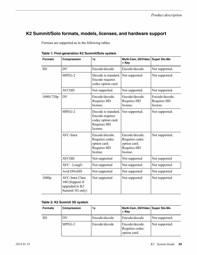
K2 Summit/Solo formats, models, licenses, and hardware support
Formats are supported as in the following tables.
Table 1: First-generation K2 Summit/Solo system
Super Slo-MoMulti-Cam, 3D/Video+ Key
1xCompressionFormats
Not supported.Encode/decodeEncode/decodeDVSD
Not supported.Not supported.Decode is standard.Encode requirescodec option card.
MPEG-2
Not supported.Not supported.Not supported.AVCHD
Encode/decode.Requires HDlicense.
Encode/decode.Requires HDlicense.
Encode/decode.Requires HDlicense.
DV1080i/720p
Not supported.Not supported.Decode is standard.Encode requirescodec option card.Requires HDlicense.
MPEG-2
Not supported.Encode/decode.Requires codecoption card.Requires HDlicense.
Encode/decode.Requires codecoption card.Requires HDlicense.
AVC-Intra
Not supportedNot supportedNot supportedAVCHD
Not supportedNot supportedNot supportedAVC - LongG
Not supportedNot supportedNot supportedAvid DNxHD
Not supportedNot supportedNot supportedAVC-Intra Class100 (Support ifupgraded to K2Summit 3G only)
1080p
Table 2: K2 Summit 3G system
Super Slo-MoMulti-Cam, 3D/Video+ Key
1xCompressionFormats
Not supported.Encode/decodeEncode/decodeDVSD
Not supported.Encode/decode.Requires codecoption card.
Encode/decodeMPEG-2
2014 01 31 K2 System Guide 33
Product description

Super Slo-MoMulti-Cam, 3D/Video+ Key
1xCompressionFormats
Not supportedNot supportedDecode only.Requires AVClicense.
AVCHD/H.264
Encode/decode. HDlicense is standard.
Encode/decode. HDlicense is standard.
Encode/decode. HDlicense is standard.
DV1080i/720p
Not supported.Encode/decode.Requires codecoption card. HDlicense is standard.
Encode/decode. HDlicense is standard.
MPEG-2
Encode/decode.Requires AVClicense. HD licenseis standard.
Encode/decode.Requires AVClicense. HD licenseis standard.
Encode/decode.Requires AVClicense. HD licenseis standard.
AVC-Intra
Not supportedNot supportedDecode only.Requires AVClicense.
AVCHD/H.264
Not supportedNot supportedDecode only.Requires AVClicense.
AVC - LongG
Encode/decode.Requires DNXlicense.
Encode/decode.Requires DNXlicense.
Encode/decode.Requires DNXlicense.
Avid DNxHD
Not supportedNot supportedEncode/decode.Requires 3Glicense.
AVC-Intra Class100
1080p
Table 3: K2 Solo 3G system
Super Slo-MoMulti-Cam, 3D/Video+ Key
1xCompressionFormats
Not supported.Encode/decodeEncode/decodeDVSD
Not supportedNot supportedEncode/decodeMPEG-2
Not supportedNot supportedDecode only.Requires AVClicense.
AVCHD/H.264
Encode/decode. HDlicense is standard.
Encode/decode. HDlicense is standard.
Encode/decode. HDlicense is standard.
DV1080i/720p
Not supportedNot supportedEncode/decode. HDlicense is standard.
MPEG-2
34 K2 System Guide 2014 01 31
Product description

Super Slo-MoMulti-Cam, 3D/Video+ Key
1xCompressionFormats
Encode/decode.Requires AVClicense. HD licenseis standard.
Encode/decode.Requires AVClicense. HD licenseis standard.
Encode/decode.Requires AVClicense. HD licenseis standard.
AVC-Intra
Not supportedNot supportedDecode only.Requires AVClicense.
AVCHD/H.264
Not supportedNot supportedDecode only.Requires AVClicense.
AVC - LongG
Encode/decode.Requires DNXlicense.
Encode/decode.Requires DNXlicense.
Encode/decode.Requires DNXlicense.
Avid DNxHD
Not supportedNot supportedEncode/decode.Requires 3Glicense.
AVC-Intra Class100
1080p
Features of internal storage models
K2 Summit/Solo systems have media drives as follows:
• First generation K2 Summit system — Up to eight media drives• K2 Summit 3G system — Up to twelve media drives• K2 Solo Media Server — Two media drives• K2 Solo 3G Media Server — Two media drives
This makes the internal storage K2 system a self-contained, stand-alone unit, with no external devicesfor storage connections required. You can transfer media in and out of the internal storage K2 systemvia Gigabit Ethernet. You can also export media to a mapped drive or USB-attached storage. Withthe K2 Solo Media Server, you can also export media via an ExpressCard.
Features of external storage models
The external storage K2 Summit system contains only the system drive. There are no media drivesin an external storage K2 Summit system. There are two types of external storage for media, asfollows:
• Shared storage — Multiple external storage K2 Summit systems connect to the K2 SAN viaGigabit Ethernet or Fibre Channel to share a common pool of storage.
2014 01 31 K2 System Guide 35
Product description

• Direct-connect storage — A single K2 Summit system with the optional Fibre Channel boardinstalled connects directly to its own external (non-shared) RAID storage device. This makesthe direct-connect K2 Summit system a self-contained, stand-alone unit, with no additionaldevices for storage connections required. You can transfer media in and out of the direct-connectK2 Summit system via Gigabit Ethernet.
Product identification K2 Summit 3G
The K2 Summit 3G system has labels affixed to the chassis that provide product identification asillustrated:
USB compartment(Clip behind bezel)Note: removing the bezel takesthe fans offline. Replace the bezel assemblywithin one minute to maintain system cooling.
Serial NumberThis is also the factorydefault hostname
Product identification first generation K2 Summit
The first generation K2 Summit system has labels affixed to the chassis that provide productidentification as illustrated:
36 K2 System Guide 2014 01 31
Product description

Serial NumberThis is also the factorydefault hostname
USB compartment(Compartment swivels up.)Note: removing the bezel takesthe fans offline. Replace the bezel assemblywithin one minute to maintain system cooling.
C1 C2 C3 C4
!
OK
~AC
!
OK
~AC
SDI IN1 S DI OUT1 S DI OUT2 LTC I/O
AES AUDIO R S422
SDI OUT1 SDI OUT2
USB/1394 100BT/1000BT
GPI
VGA REF. LOOP THROUGH
AES AUDIO R S422
LTC I/OSDI IN2 S DI IN3 S DI IN1 S DI IN2 S DI IN3 SDI IN1 S DI OUT1 S DI OUT2 LTC I/O
AES AUDIO R S422
SDI OUT1 SDI OUT2
AES AUDIO R S422
LTC I/OSDI IN2 S DI IN3 S DI IN1 S DI IN2 S DI IN3
Type II labelIdentifies Type II carrier module
Product identification K2 Solo
K2 Solo system have labels affixed to the chassis that provide product identification as illustrated:
Serial NumberThis is also the factorydefault hostname
Front panel indicators K2 Summit 3G system
With the front bezel in place, the indicator LEDs are visible. The LEDs indicate the status of themachine. For example, when the Service LED is a steady yellow light, this could signify that one
2014 01 31 K2 System Guide 37
Product description

of the power cables is unplugged. For more information on indicator LEDs, see the service manualfor your K2 product.
PowerLED
Standbyswitch
ServiceLED
Front panel indicators first-generation K2 Summit
With the front bezel in place, the indicator LEDs are visible. The LEDs indicate the status of themachine. For example, when the Service LED is a steady yellow light, this could signify that oneof the power cables is unplugged. For more information on indicator LEDs, see the service manualfor your K2 product.
PowerLED
Standbyswitch
ServiceLED
Front panel indicators K2 Solo
Both the first-generation K2 Solo system and the K2 Solo 3G system have the same front panelindicators. With the front bezel in place, the indicator LEDs are visible. The LEDs indicate the statusof the machine. For example, when the Service LED is a steady yellow light, this could signify thatone of the power cables is unplugged. For more information on indicator LEDs, see the servicemanual for your K2 product.
38 K2 System Guide 2014 01 31
Product description

Rear panel view
The following illustrations identify the rear panel connectors and components.
K2 Summit 3G models rear panel
!
OK
~AC
C1 C2 C3 C4
USB/1394 100BT/1000BT
GPI
VGAREF. LOOP THROUGH
!
OK
~AC
!
OK
~AC
C1 C2 C3 C4
USB/1394 100BT/1000BT
GPI
VGAREF. LOOP THROUGH
!
OK
~AC
PowerPower
Port 1: Control
Port 2: FTP/Streaming
Control Connection #1Control Connection #2
Media Connection #1
Port 4: Control(Optional)
Port 1: Control AControl Connection #1
Control Connection #2
Media Connection #1
Port 4: Control Bfor redundant SAN
Port 2: Media (iSCSI) A
Media Connection #2
Port 3: Media (iSCSI) Bfor redundant SAN
IEEE1394
(Do notuse)
Optional Fibre Channelcard for connection todirect-connect storageor shared (SAN) storage
ReferenceLoop Thru
VGAmonitor
USB(keyboard,
mouse)
GPI
Channel 1
Stand-alone direct-connector internal storage
Shared (SAN)storage
Channel 2 Channel 3 Channel 4
Control Connections are teamedand share the same IP address
c
c c
c c
SupportsChannel Flex Suite,which requiresAppCenterElite license
a Supports Super Out,which requiresAppCenter Pro orElite license
b
RS-422
(connect via optionalmulti-connector cable)
LTC in/outAES audio
SDI video in and out supports embedded audio.
SDI in SDI out SDI monitor out.Channel Flex aa a a, b
2014 01 31 K2 System Guide 39
Product description

K2 Summit first generation models rear panel
RS-422
SDI video in and out supports embedded audio.
(connect via optionalmulti-connector cable)
LTC in/out
AES audio
PowerPower
Port 1: Control
Port 2: FTP/Streaming
Control Connection #1Control Connection #2
Media Connection #1
Port 4: Control(Optional)
Port 1: Control AControl Connection #1
Control Connection #2
Media Connection #1
Port 4: Control Bfor redundant SAN
Port 2: Media (iSCSI) A
Media Connection #2
Port 3: Media (iSCSI) Bfor redundant SAN
IEEE1394
(Do notuse)
Optional Fibre Channelcard for connection todirect-connect storageor shared (SAN) storage
ReferenceLoop Thru
VGAmonitor
USB(keyboard,
mouse)
GPI
Channel 1
Stand-alone direct-connector internal storage
Shared (SAN)storage
Channel 2 Channel 3 Channel 4
Control Connections are teamedand share the same IP address
c
c cc c
SDI in SDI out SDI monitor out.Channel Flex aa a a, b
SupportsChannel Flex Suite,which requiresAppCenterElite license
a Supports Super Out,which requiresAppCenter Pro orElite license
b
40 K2 System Guide 2014 01 31
Product description

K2 Solo 3G Media Server rear panel
2014 01 31 K2 System Guide 41
Product description

K2 Solo Media Server rear panel
RS-422
SDI in SDI out SDI monitor out.
(connect via optionalmulti-connector cable)
LTC in/out
AES audio
Power
Port 1: Control
Port 2: FTP/Streaming
Control Connection #1Control Connection #2
Media Connection #1
Port 4: Control(Optional)
IEEE1394
(Do notuse)
ReferenceLoop Thru
VGAmonitor
USB(keyboard,
mouse)
GPI
Channel 1 Channel 2
Channel Flex
SDI video in and out supports embedded audio.
SupportsChannel Flex Suite,which requiresAppCenterElite license
a
aa a a, b
Supports Super Out,which requiresAppCenter Pro orElite license
b Control Connections are teamedand share the same IP address
c
cc
ChannelFlex rear panel connections
ChannelFlex Suite features require the AppCenter Elite license. Super Slo-Mo also requires the HDlicense. When configured for these features, channel connections are as follows:
42 K2 System Guide 2014 01 31
Product description

Phase 1 Phase 2 Phase 3
Super Slo-Mo RecorderVideo 1 Video 2
Multi-Cam Recorder
Video orLeft eye
Key orRight eye
3D/Video + Key RecorderVideo orLeft eye
Key orRight eye
3D/Video + Key Player
ChannelFlex Suite features do not support AVC-Intra Class 100.
Refer to the K2 AppCenter User Manual for more information on ChannelFlex Suite features.
Considerations for first startup out of box
When you receive a K2 system from the factory, one or more End User License Agreements (EULAs)appear on the screen at first startup. Software licensing agreements require that you accept theseEULAs. When you do so, start up processes can proceed. This behavior occurs only at first startup.Subsequent startups do not exhibit this behavior.
K2 Summit/Solo system overview
The K2 Summit/Solo system are purpose-built clients based on COM Express compact computerwith dedicated systems to provide the video disk recorder functionality. This section explains themajor architectural blocks.Related Topics
Application System on page 44Real Time System on page 44Media control and processing on page 44Loop through, E to E, and feeds on page 45
2014 01 31 K2 System Guide 43
Product description

Application System
The K2 Summit Production Client and K2 Solo Media Server application system architecture usesthe COM Express form factor to provide functionality similar to that of standard PC-type computers.The carrier module contains a CPU module, built in Ethernet, and USB ports. On the K2 SummitProduction Client, the carrier module also includes one PCIe board slot for expansion.
The Application system uses a Windows embedded operating system upon which all internal storageK2 system applications run for configuration and control of the unit.
Real Time System
Each channel hosts a complete Real Time system that provides the core video disk recorderfunctionality. Primary components are as follows:
• Dedicated processor for media access and processing.• Codec circuits responsible for encoding/decoding video and processing audio and timecode,
including the media-related input and output connectors.
The Real Time system uses a dedicated operating system. This operating system manages all thehardware involved in controlling the flow of video, audio, timecode, genlock, and GPI in and outof the K2 system.
Media control and processing
The following section explains how the Application system and the Real Time system work togetherto provide K2 system functionality.
The high processing requirements of digital video can overwhelm the processor on a standard desktopPC, resulting in wait-times that destroy the video’s essential real-time aspect. The K2 system avoidsthis problem by providing dedicated systems that isolate processing needs. The components thatwork together to provide this functionality are as follows:
Application system — Dedicated to control, configuration, and networking functions that do notrequire real-time accuracy. The Application system has the following components:
• Application software provides the user interface for operating the K2 system. The software runsas Windows programs.
• The Media File system manages clips. It includes a database that associates the clip with itsvideo, audio, and timecode files and a dedicated file system (separate from the Windows filesystem) that controls access to the raw data that makes up each file. Any reading and writing ofclips, be it through play and record operations or through file transfers and media streaming, ismanaged by the database. The database and file system run as Windows programs.
Storage system — Includes the media disk drives, controllers, drivers, and adapters necessary foraccess and movement of the data. While the primary data flow is within the overall control of theReal Time system, some components and their communication pathways cross over into theApplication system. For example, the media drives appear as the V: drive to the Windows operatingsystem.
44 K2 System Guide 2014 01 31
Product description

Real Time system — Manages the media flow between the Storage system and the inputs and outputs.The Real Time system has dedicated processors and time-sensitive mechanisms to serve mediaprocessing needs while maintaining real-time accuracy.
When you control play and record operations from within the Application system you trigger a chainof events that eventually crosses over into the Real Time system and results in media access. Thefollowing sequence is an example of this type of chain of events:
1. A user operates the Player application to play a particular clip. The Player application asks theMedia File system for permission to access the clip. The Media File system grants access. Inshared storage models, the Media File system enforces shared storage policies in order to grantthe access. When access is granted, the Player application initiates play access to the clip.
2. The database identifies the files that make up the clip and the file system instructs the Storagesystem to open access to the files.
3. The Storage system finds the raw data and opens the appropriate read access. At this point boththe Application system and the Real Time system are involved. Windows controls the mediadrives and controllers, so the Real Time system makes file requests to Windows and it causesthe data to be transferred to buffers on the Real Time processor. The data is then available to theReal Time system so that it can be processed at exactly the right time.
4. The Real Time system processes the media, decompresses it, adjusts its timing, and moves it asrequired to play the clip as specified by the user.
Loop through, E to E, and feeds
Behaviors related to input signals routed to output connectors are described in the following topics.Related Topics
About remote control protocols on page 197
Recording synchronous and asynchronous feeds
For best results in all workflows, use synchronous feeds, defined as follows:
• All outputs are locked to the house reference• All inputs are genlocked to the house reference and at zero time
The K2 Summit Production Client and K2 Solo Media Server can record inputs that are asynchronous,with the following considerations:
• The encoder clock and the audio clock are derived from the input signal, which enables frameaccurate recording of all inputs.
• Outputs are timed to the reference and if no reference is present, the output runs free.• If the input video rate does not equal the output video rate (asynchronous) then video tearing or
jumping can occur when input/output synch is critical, such as in the following:
• K2 TimeDelay• SD-00 or Summit E-to-E (LoopThru) mode• HD-00 Loopback
2014 01 31 K2 System Guide 45
Product description

Loop through on K2 Summit/Solo
The Player/Recorder application has a “E-to-E (LoopThru) mode” selection on the Control menu.This mode applies when the channel is under local AppCenter control as well as when it is underremote control, for all protocols.
This “E-to-E (LoopThru) mode” feature allows you to monitor the video that is being recorded. Thevideo is routed back essentially untouched. Any audio or timecode that is on the input video streamis still there on the loop through output. The K2 Summit/Solo system and the loop through videosmust be locked to a video reference for the loop through feature to work properly. This “E-to-E(LoopThru) mode” feature should not be confused with true E to E. True E to E is not supported onthe K2 Summit/Solo system.
When “E-to-E (LoopThru) mode” is not selected, the channel behaves as follows:
• “PB” is displayed on the channel pane, next to the Timecode Source indicator.• When no clip is loaded, black plays out.• When a record operation stops, Recorder becomes Player and the clip remains in the Player. The
clip’s last frame plays out.
When “E-to-E (LoopThru) mode” is selected, the channel behaves as follows:
• “EE” is displayed on the channel pane, next to the Timecode Source indicator.• When no clip is loaded, the signal that is currently present at the channel input plays out.• When a record operation stops, Recorder stays Recorder and the clip remains in the Recorder.
The signal that is currently present at the channel input plays out.
Ports used by K2 services
The following ports are used by the applications and system tools of the K2 family of products:
TCP: Used by mpgsession.exe, mxfsession.exe, gxfsession.exe, or ftpd.exe for FTP.20
TCP: Used by ftpd.exe for FTP data.21
UDP: Used by snmp.exe for SNMP.161
UDP: Used by snmptrap.exe for SNMP trap.162
TCP: Used by Remote Desktop for use by SiteConfig.3389
Protocol: TCP. Used by Grass Valley AppService for 3rd party applications tocommunicate using AMP protocol. Used by SDB Server and Aurora Playoutoutgoing AMP communication to control playout channels.
3811
Protocol: TCP. Traffic: HTTP. Used by GV STRATUS Summit Services. Used byWCF service provided by the GV STRATUS Workflow Engine. Used by WCFservice provided by the GV STRATUS Rules Engine.
8080
HTTP/TCP: Used by Macintosh systems for the SabreTooth licensing web serviceto check out licenses
8100
Protocol: TCP. Traffic: HTTP. Used by Site Config data service .8732
Protocol: TCP. Traffic: HTTP. Used by K2 Config data service .8733
46 K2 System Guide 2014 01 31
Product description

Protocol: TCP. Traffic: HTTP. Used by Site Config data service .8734
Protocol: TCP. Traffic: HTTP. Used by K2 Config data service.8735
TCP: Used by GV ProductFrame Configuration Service, ProductFrame DiscoveryAgent Service for use by SiteConfig. Used by GV NetConfig Service. gv-pf. UDP:Used by GV NetConfig Service. gv-pf.
18262
UDP: Used by ProductFrame Discovery Agent Service for GV NetConfig DeviceBroadcast/Unicast Protocol. Used by SiteConfig. Sent by ControlPoint, receivedby Devices
18263
UDP: Used by ProductFrame Discovery Agent Service for GV NetConfig ControllerProtocol. Used by SiteConfig. Sent by Devices, received by ControlPoint
18264
Protocol: UDP. Used for live streaming from K2 Summit/Solo systems. This is thedefault base for UDP ports, with the range being 31820 to 31827. Other ranges arepossible, depending on the UDP port base configured on the K2 Summit/Solo system.
31820
HTTP/TCP: Used by Grass Valley K2 Config for K2Config application connectionbetween a control point PC and the K2 system device configured. Used for mostfunctions.
49168
TCP: Used by Grass Valley K2 Config for K2Config application connection betweena control point PC and the K2 system device configured. Used for a few functionsthat require longer time periods.
49169
HTTP: Used by Grass Valley Transfer Queue Service for Transfer Managerconnection between source system and destination system.
49170
TCP: Used by Grass Valley AppService for AppCenter connection between controlpoint PC and K2 client/Solo.
49171
HTTP: Used by Grass Valley Storage Utility Host for connection for Storage Utilitybetween the control point PC and the K2 system being configured.
49172
UDP: Used by K2 Appcenter to discover K2 systems on the network.50872
RAID drive numbering K2 Summit 3G system
In the K2 Summit 3G system, internal RAID drives are numbered as follows. This numbering isdisplayed in Storage Utility.
Disk0
Disk1
Disk2
Disk3
Disk4
Disk5
Disk6
Disk7
Disk8
Disk9
Disk10
Disk11
Drives are configured as RAID 1.
ExplanationDrive numbering
These two RAID drives make up LUN 0.Disk 0
Disk 1
2014 01 31 K2 System Guide 47
Product description

ExplanationDrive numbering
These two RAID drives make up LUN 1.Disk 2
Disk 3
These two RAID drives make up LUN 2.Disk 4
Disk 5
These two RAID drives make up LUN 3.Disk 6
Disk 7
These two RAID drives make up LUN 4.Disk 8
Disk 9
These two RAID drives make up LUN 5.Disk 10
Disk 11
RAID drive numbering first generation K2 Summit system
In the first generation K2 Summit system, internal RAID drives are numbered as follows. Thisnumbering is displayed in Storage Utility. You cannot see the labeling on the K2 Summit ProductionClient chassis RAID drive when you remove the fan module.
Disk 2 Disk 4 Disk 7
Disk 1 Disk 3 Disk 6
Disk 0 Disk 5
ExplanationDrive numbering
When configured as RAID 1, these two RAID drives make up LUN 0.Disk 0
Disk 1
When configured as RAID 1, these two RAID drives make up LUN 1.Disk 2
Disk 3
When configured as RAID 1, these two RAID drives make up LUN 2.Disk 4
Disk 5
When configured as RAID 1, these two RAID drives make up LUN 3.Disk 6
Disk 7
When drives are configured as RAID 0, each drive is considered its own LUN. As such, the orderof LUNs and drive numbers as displayed in Storage Utility does not always correlate with the positionof drives in the chassis.
48 K2 System Guide 2014 01 31
Product description

RAID drive numbering K2 Solo system
In the K2 Solo system, internal RAID drives are numbered as follows.
Disk 0
Disk 1
NOTE: K2 Solo system drives are always configured as RAID 0.
When drives are configured as RAID 0, each drive is considered its own LUN. As such, the orderof LUNs and drive numbers as displayed in Storage Utility does not always correlate with the positionof drives in the chassis.
2014 01 31 K2 System Guide 49
Product description

50 K2 System Guide 2014 01 31
Product description

Overview of K2 System tools
Configuration Manager
The Configuration Manager is the primary configuration tool for a K2 Summit/Solo system. It makessettings that apply to the overall internal storage K2 Summit/Solo system as well as settings thatapply to individual channels.
Configuration Manager settings are stored in a database. When the K2 Summit/Solo system startsup it reads the current settings from the database and configures itself accordingly. When you modifya setting in Configuration Manager you must save the setting in order to update the database andreconfigure the K2 Summit/Solo system.
You can also save settings out of Configuration Manager into a configuration file, which is astand-alone XML file. Likewise, you can load settings into Configuration Manager from aconfiguration file. However, you must use Configuration Manager as the means to save the settingsto the database before the settings actually take effect. Configuration files are not linked directly tothe database.
You can use configuration files as a means to back up your settings. You can also use configurationfiles to save several different groups of customized settings, each with a unique name, so that youcan quickly load settings for specialized applications.
If you save a configuration file and then upgrade your K2 system software, there can be compatiblityissues. If the upgraded software version has new features, the saved configuration file might not becompatible.
2014 01 31 K2 System Guide 51

Accessing Configuration Manager
You access Configuration Manager through the K2 AppCenter application from the local K2Summit/Solo system or from the Control Point PC.
To access the configuration settings, open AppCenter and select System | Configuration.
Saving and restoring Configuration Manager settings
Settings can be saved as a configuration file. You can save any number of uniquely named customconfiguration files. You can load a configuration file to restore system settings.
To save custom settings:
1. In the Configuration Manager, click the Save button.The Save As dialog opens.
2. Use the up arrow or select folders to navigate to the folder in which you want to save theconfiguration file.
3. Enter a name for the configuration file.Do not name the file DefaultConfig.xml, as this name is reserved for the factory defaultconfiguration file. Otherwise, standard Windows 2000 and up file naming restrictions apply.
4. Click Save and Close.
52 K2 System Guide 2014 01 31
Overview of K2 System tools

To restore custom settings:
1. If you want to save current settings, you should save them as a configuration file before continuing.2. In the Configuration Manager, click the Load button.
The Open dialog opens.
3. Use the up arrow or select folders to navigate to the custom configuration file.4. Select the custom configuration file.5. Click Open.
The custom settings are loaded into Configuration Manager, but they have not been saved andput into effect.
6. Click OK to save and apply settings, and to close the Configuration Manager.
Restoring default Configuration Manager settings
You can restore factory default settings as follows:
• Restore some individual settings or groups of settings by selecting the Default button whichappears below the settings in the configuration screen.
• Restore all the settings in Configuration Manager at once to their default values as explained inthe following procedure.
1. If you want to save current settings you should do so before proceeding.2. In the Configuration Manager dialog, click Restore.
The default settings are loaded into Configuration Manager, but they have not yet been savedand put into effect.
3. Click OK to save settings and close Configuration Manager.
Related Topics
Saving and restoring Configuration Manager settings on page 52
K2Config
The K2 System Configuration application (K2Config) is the primary tool for configuring systemsin the category of a K2 SAN, which include online or production K2 SANs, K2 Nearline systems,and GV STRATUS Proxy Storage systems. Once the devices of the storage system are cabled andare communicating on the control network, you can do all the configuration required to create aworking K2 SAN using the K2Config application. When you use SiteConfig for networkconfiguration, you can import the SiteConfig system description file into the K2Config applicationto get you started with your SAN configuration.
After your K2 SAN is initially installed and configured, if you need to reconfigure the system youshould do so using SiteConfig and the K2Config application. This enforces consistent policy andsequencing for configuration tasks, which makes the system easier to maintain and aids introubleshooting should a problem arise.
2014 01 31 K2 System Guide 53
Overview of K2 System tools

The K2Config application runs on a control point PC and accesses the devices of the K2 SAN viathe control network. You can configure the devices of the K2 SAN as follows:
• SAN-attached K2/Summit systems and K2 Media Server — These devices are configured directlyby the K2Config application.
• K2 RAID storage devices — The K2Config application launches a remote instance of StorageUtility, which configures RAID storage devices. Storage Utility components run on the K2 MediaServer and the configuration actually takes place via the Fibre Channel connection between theK2 Media Server and the RAID storage device.
• Ethernet switches — The K2Config application can launch a switch’s web-based configurationapplication.
You can expand and select nodes in the tree view to view K2 SANs, individual devices, andconfiguration settings. The configuration file is saved on the V: drive, along with the media files inthe shared storage system. The configuration file is updated and saved whenever you change aconfiguration using the K2Config application. That is why you must always use the K2Configapplication to change settings on the storage system, so the most recently changed configurationswill always be stored in the configuration file and displayed.
Opening the K2Config application
1. On the control point PC open the K2Config application shortcut on the desktop. The K2Configapplication log in dialog box opens.
2. Log in using the designated administrator account for configuring K2 SAN devices.
54 K2 System Guide 2014 01 31
Overview of K2 System tools

3. The K2Config application opens.
If you have one or more K2 SANs currently configured, the K2Config application displays thesystems in the tree view.If you have not yet configured a K2 SAN, the K2Config application opens with the tree viewblank.
Storage Utility for standalone K2 Summit/Solo system
There are two versions of Storage Utility:
• Storage Utility for the K2 SAN• Storage Utility for stand-alone K2 systems
This manual explains Storage Utility for stand-alone K2 Summit/Solo system. Refer to the K2 SANInstallation and Service Manual to learn about Storage Utility for the K2 SAN.NOTE: For shared storage, run Storage Utility only via the K2Config application.
The Storage Utility is your primary access to the media file system, the media database, and themedia disks of the K2 Summit/Solo system for configuration, maintenance, and repair. It is launchedfrom the K2 AppCenter application.
CAUTION: Use the Storage Utility only as directed by a documented procedure or by GrassValley Support. If used improperly, the Storage Utility can render your K2 system inoperableor result in the loss of all your media.
NOTE: Do not use theMegaRAID utility on a K2 system. This utility is for use by qualified GrassValley Service personnel only. When this utility is opened it scans the SCSI bus and interfereswith record and play operations.
2014 01 31 K2 System Guide 55
Overview of K2 System tools

Remote Desktop Connection
You can use the Microsoft Windows Remote Desktop Connection application to make a remoteconnection to a Grass Valley system that runs the Windows operating system.
Take the following into consideration when connecting to K2 systems:
• Before you can use the Remote Desktop Connection, you need network access and permissionsto connect to the K2 system.
• You can use either the name or the IP address to access the K2 system.• Do not use the Remote Desktop Connection to access the PC running the Control Point software
or to access the AppCenter application; results may be unreliable.• Take care when accessing an online K2 system on which media access is underway. The additional
load on network and system resources could cause unpredictable results.• Lack of robust video/graphic support can cause video display problems. Remote desktop
connections can interrupt proxy and live streaming. AppCenter video monitoring is not supportedthrough Remote Desktop Connection.
Accessing Remote Desktop Connection
1. Do one of the following:
• Click the Start button on the Windows task bar• Press the Windows key on the keyboard.
2. Select Programs | Accessories | Communications | Remote Desktop Connection.The Remote Desktop dialog box opens.
3. Enter the name or IP address of the system to which you are making the remote connection andclick Connect.
About SiteConfig
SiteConfig is Grass Valley's tool for network configuration and software deployment. SiteConfigis a ProductFrame application. ProductFrame is an integrated platform of tools and productdistribution processes for system installation and configuration.
You can use SiteConfig as a stand-alone tool for planning and system design, even before you haveany devices installed or cabled. You can define networks, IP addresses, hostnames, interfaces, andother network parameters. You can add devices, group devices, and modify device roles in thesystem.
As you install and commission systems, SiteConfig runs on a designated PC. It discovers devices,configures their network settings, and manages host files. SiteConfig also manages softwareinstallations and upgrades and provides a unified software package with compatible versions fordeployment across multi-product systems.
You should use SiteConfig for network configuration and software deployment at installation andthroughout the life of the system in your facility. This enforces consistent policy and allows SiteConfig
56 K2 System Guide 2014 01 31
Overview of K2 System tools

to keep a record of changes, which makes the system easier to maintain and aids in troubleshootingshould a problem arise.
SiteConfig displays information from a system description file, which is an XML file.
Opening SiteConfig
1. Do one of the following: Use the SiteConfig shortcut on the Windows desktop or in the Startmenu to open SiteConfig.
• On the Windows desktop, click the Grass Valley SiteConfig shortcut.• On the Windows Start menu, in the Grass Valley folder, click the SiteConfig shortcut.
2. SiteConfig opens as follows:
• If you have previously opened SiteConfig, the SiteConfig main window opens with the mostrecently used system description loaded.
• If you have not previously used SiteConfig or if SiteConfig does not have access to a systemdescription file, you are prompted to create a new system description or to import an existingsystem description.
3. Respond as appropriate.
SiteConfig main window
The SiteConfig main window is as follows:
2014 01 31 K2 System Guide 57
Overview of K2 System tools

The left side of the screen shows the tree view of the currently loaded system description. TheNetwork Configuration and Software Deployment buttons at the bottom of the tree view activateeither the network configuration workspace or the software deployment workspace.
The network configuration workspace on the left has two tabs: a Devices tab to display the tree ofdevices in the system and a Networks tab to show the hierarchy of networks defined in the system.
The software deployment workspace also has two tabs: a Devices tab that displays the same treeview of devices but provides information about the software roles assigned to the devices and thesoftware currently installed on devices. The Deployment Groups tab provides the interface to managesoftware deployment tasks.
Select an item in the tree and the view on the right side of the screen shows details about the itemselected. Select a site or group to show information about all the items that fall under the selecteditem.
Right-click an item to access a context menu of operations.
Icon overlays on items and tooltips provide status and warning feedback.
Grass Valley Recommended Deployment and Monitoring Solutions
To maximize up-time, a maintenance strategy must provide the ability to easily identify the rootcause of an unanticipated hardware or software failure and to quickly compile failure data. Theability to proactively predict failures and to quickly notify those who can rectify them makes themaintenance strategy even more powerful. Grass Valley has a long history of building the necessaryfunctionality into critical broadcast products. Beginning with Grass Valley’s longstanding monitoringapplication NetCentral and progressing to the next generation tool GV GUARDIAN, remotemonitoring and proactive predictive failure analysis are important contributors to Grass Valleysystem solutions. Both NetCentral and GV GUARDIAN run on commercial off-the-shelf serverPCs, such as the K2 system control point PC. Grass Valley and 3rd party devices report status viaWindow Messaging, Simple Network Management Protocol (SNMP), or syslog to the NetCentralor GV GUARDIAN application. Each application provides easy to use, fully autonomous remotemonitoring to predict errors, provide proactive notifications, and centrally consolidate error logsand hardware failure information. Grass Valley recommends using a remote monitoring tool likeNetCentral or GV GUARDIAN. With NetCentral, and even more so with GV GUARDIAN, youcan maximize your up-time with less manpower, as compared to manual system monitoring. Watchingfor indicator lights, physically scanning logs, and other manual monitoring is far more timeconsuming, more error-prone, and much less accurate. If you have an existing NetCentral installationyou install a NetCentral device provider on the NetCentral server PC for each type of device youare monitoring. Refer to NetCentral product documentation for installation and operating instructions.With GV GUARDIAN, only SNMP MIBs are required. Separate device providers are not necessary.Refer to the on-line GV GUARDIAN Topic Library for information.
58 K2 System Guide 2014 01 31
Overview of K2 System tools

System connections and configurations
About networks
The following section describe networks as they apply to K2 systems. Also refer to the K2 SANInstallation and Configuration Guide for more detailed information about K2 SAN networking.
Control network description
The control network is for communication between devices and components. It does not havereal-time media traffic or streaming/FTP media traffic. The control network traffic must be separatedfrom the streaming/FTP network traffic and the media (iSCSI) network traffic. This separation maybe provided by different subnets, VLANs, or physical switch fabrics. The control network and thestreaming/FTP network, if on different subnets, may be on the same VLAN. The control networkand the media (iSCSI) network must not be on the same VLAN. Static IP addresses with nameresolution via host files are recommended for the control network.
Streaming/FTP network description
The streaming/FTP network is for media transfers and FTP traffic. The streaming/FTP networknetwork traffic must be separated from the control network traffic and the media (iSCSI) networktraffic. This separation may be provided by different subnets, VLANs, or physical switch fabrics.The control network and the streaming/FTP network, if on different subnets, may be on the sameVLAN. The control network and the media (iSCSI) network must not be on the same VLAN. StaticIP addresses with name resolution via host files are recommended for the streaming/FTP network.Hostnames of network adapters that are dedicated to the streaming/FTP network must be aliased inthe hosts file with the _he0 suffix. This directs the streaming traffic to the correct port.
Media (iSCSI) network description
The media network is exclusively for real-time iSCSI traffic on a K2 SAN. It must be on a differentsubnet than the control network and the streaming/FTP network. Furthermore, its traffic is keptphysically separate from that of other networks. This separation is provided by dedicated ports,cables, and by a dedicated VLAN on the Ethernet switch or by separate switches. Static IP addressesare required for the media network. Name resolution is not necessary, so media network IP addressesare not required in host files.
Network considerations and constraints
• If your GV STRATUS system is on a domain, all servers and client PCs on that system that haveany interaction with Grass Valley components must be logged on to Windows with a domainuser account. Do not use a local user account.
2014 01 31 K2 System Guide 59

• Do not use any 10.1.0.n or 10.2.0.n IP addresses. These are used by the K2 RAID maintenanceport and must be reserved for that purpose. If these addresses are otherwise used, maintenanceport communication errors occur.
Network connections
Use the information in this section as appropriate to connect the Gigabit (1GBaseT) Ethernet networkfor your application:
Ethernet cable requirements
For making Ethernet connections, cabling must meet the following requirements:
• Use CAT5e or CAT6 cables. The maximum cable length is 50 meters for CAT5e and 100 metersfor CAT6.
About network ports
When you receive a K2 Summit Production Client or K2 Solo Media Server from the factory, it hasa specific network configuration, including a loopback adapter and two of the four Gigabit Ethernetports configured as a teamed pair. The Gigabit Ethernet ports, as viewed when looking at the rearpanel, are represented in the following illustration.
12 3
4Control Team: Same for internal, direct-connect, and SAN storage.
iSCSI:SANstorage
iSCSI:RedundantSAN stor-age
Control:Internal,direct-connect,and SANstorage
Control:RedundantSAN stor-age
FTP/Streaming:Internal and
direct-connect stor-age
MediaConnection #1
ControlConnection #1
ControlConnection #2
MediaConnection #2
The K2 Solo Media Server is not supported for SAN (shared storage) connection.
60 K2 System Guide 2014 01 31
System connections and configurations

Making network connections
Connect network ports as appropriate for the K2 Summit/Solo system storage option as in thefollowing illustrations. In these illustrations the first generation K2 Summit system is shown.Connections are identical on the K2 Summit 3G system.
Control network Optional connection forredundant control network
Port
1
Port
2Port
3Port
4
FTP/streamingnetwork
Stand-alone storage K2 Summit/Solo network connections
On a K2 Solo Media Server, an internal storage K2 Summit system, or a direct-connect storage K2Summit system, connect the control network to port 1, which is the first port of the control team. Ifyou have a FTP/streaming network, connect that network to port 2. Port 3 is not used. In most casesport 4, which is the second port of the control team, is not used, although it is available to provideadditional redundancy for the control network connection.
Control network Optional connection forredundant control network
Port
1
Port
2Port
3Port
4
Media (iSCSI)network
Basic shared storage (SAN) K2 Summit system network connections
On a non-redundant shared storage (SAN) K2 Summit system, connect the control network to port1, which is the first port of the control team. Port 2 must be connected to the media (iSCSI) network.Port 3 is not used. Port 4, which is the second port of the control team, is not used except as follows:Port 4 may be used only if you extend your control network to provide the same redundancy as thatof a redundant K2 SAN.
Refer to the K2 SAN Installation and Service Manual for more information.
2014 01 31 K2 System Guide 61
System connections and configurations

Port
1
Port
2Port
3Port
4
Media (iSCSI)network B
Redundant shared storage (SAN) K2 Summit system network connections
Control network A
Media (iSCSI)network A
Control network B
On a redundant shared storage (SAN) K2 Summit system, you must connect both ports of the controlteam. Connect control network connection A to port 1 and control network connection B to port 4.You must also connect both media ports. Connect port 2 to the A media network and port 3 to theB media network. The media ports must not be teamed, as doing so interferes with failoverfunctionality.
Refer to the K2 SAN Installation and Service Manual for more information.
Network configuration
This section contains instructions for configuring network connections.
About network functionality
K2 networks support the following:
• Remote control and configuration of the internal storage K2 system using AppCenter from aControl Point PC.
• Remote control of the internal storage K2 system using devices and applications softwaredeveloped for the K2 system that use industry standard remote control protocols over Ethernet.
• Stream media transfers between K2 systems and other supported Grass Valley systems. Streamingtransfers allow loading and playing a clip before the transfer is complete.
• Standard data network capability.• General networking tasks such as file sharing and mapping network drives.
The procedures in this section guide you to relevant settings, but do not instruct you on the specificsettings required for your network. It is assumed that you understand Ethernet networks in generaland your particular network needs and that you can apply that understanding to make the requiredsettings using standard Windows procedures. If you need help with these procedures, contact yournetwork administrator.
Refer to the K2 SAN Installation and Service Manual for network configuration procedures forshared storage K2 clients.
62 K2 System Guide 2014 01 31
System connections and configurations

About modifying or restoring network settings
Before configuring network settings, consider the following:
• Loopback adapter — When you receive a K2 Summit Production Client, a K2 Solo Media Server,or a K2 Media Client from the factory, it has a loopback adapter installed. The loopback adapterallows the media file system to continue operating if an Ethernet cable is disconnected. Do notmodify the loopback adapter. If you need to restore the loopback adapter, refer to the ServiceManual for your K2 product.
The loopback IP address is 192.168.200.200. Keep that IP address reserved on your network.Do not assign it to any other device. If this causes conflicts with your existing network, consultyour Grass Valley representative.
• Hostname changes — If you change the host name, remote AppCenter and other systems couldhave difficulty connecting. On a shared storage K2 client, Grass Valley strongly recommendsthat you do not change the host name or IP address unless following the documented procedure.For more information, refer to the K2 SAN Installation and Service Manual.
• Restoring factory default network settings — Several settings are configured at the factory andshould never be modified. If you suspect settings have been changed, you should reimage theK2 system to restore settings. Refer to the Service Manual for your K2 product for recoveryimage and network configuration procedures.
Related Topics
Embedded Security modes and policies on page 171
Configure network settings for a stand-alone K2 systems
Stand-alone K2 systems with internal or direct-connect storage ship from the factory DHCPconfigured. If your control network has DHCP/DNS and you are satisfied to use the factory defaulthost name (which is the serial number), then no local configuration of the control connection isrequired.
If the Windows network settings need to be configured, you must have Windows administratorsecurity privileges on the K2 system.
1. Access the Windows desktop on the K2 system. You can do this locally with a connectedkeyboard, mouse, and monitor or remotely via the Windows Remote Desktop Connection.
2. Open the Network Connections Control Panel.3. Continue with standard Windows procedures to configure the TCP/IP protocol properties. You
can set up the network using DHCP, DNS, WINS, or other standard networking mechanisms.
NOTE: On small networks or networks with certain security policies a DHCP server or domainname server (DNS) might not be available. In this case you can set up a static IP address andcreate a host file on each K2 system.
2014 01 31 K2 System Guide 63
System connections and configurations
4. Configure the control connection on the K2 system as follows:a) Configure the network connection with the following name:
Control Team
The control team is GigE ports 1 (Control Connection #1) and 4 (Control Connection #2) onthe rear panel.
CAUTION: Under no circumstances should you modify the loopback adapter. Theloopback IP address is 192.168.200.200. Keep that IP address reserved on your network.Don’t assign it to any other device. If this causes conflicts with your existing network,consult your Grass Valley representative.
5. Configure the FTP/streaming connection (if needed) on the K2 system.This connection must have an IP address that is on a different subnet from the control connection.There are special name resolution requirements for the FTP/streaming network.Configure as follows:a) Configure the network connection with the following name:
Media Connection #1
This is GigE port 2 on the rear panel.
6. If prompted, shutdown and restart Windows.7. If you are going to FTP/stream video between K2 systems, configure for streaming video between
K2 systems; otherwise, the K2 system is ready for standard data networking tasks.
Related Topics
Embedded Security modes and policies on page 171
Streaming video between K2 systems
It is required that FTP/streaming traffic be on a separate subnet from control traffic and, in the caseof a K2 SAN with shared storage K2 clients, separate from media (iSCSI) traffic. To reservebandwidth and keep FTP/streaming traffic routed to dedicated ports, IP addresses for FTP/streamingports must have double name resolution such that hostnames are appended with the “_he0” suffix.You can use host tables or another mechanism, such as DNS, to provide the name resolution. Thisdirects the streaming traffic to the correct port.
In most K2 systems, network name resolution is provided by host tables, which are found in hostsfiles. The following procedure describes how to set up hosts tables to provide name resolution forboth the control network and the FTP/streaming network. If you are using other mechanisms forname resolution, use the host table examples here to guide you. For shared storage K2 clients, alsorefer to the K2 SAN Installation and Service Manual for a discussion of host tables.
Setting up the K2 system for FTP/streaming transfer has the following network requirements:
• For stand-alone internal storage K2 systems, the K2 machine is the source/destination forFTP/streaming transfers. FTP/streaming traffic uses the FTP GigE port (Media Connection #1)on the K2 client.
64 K2 System Guide 2014 01 31
System connections and configurations

• For K2 Summit Production Clients or K2 Media Clients with shared storage on a K2 SAN, a K2Media Server is the source/destination for FTP/streaming transfers. FTP/streaming traffic usesthe FTP GigE port on the K2 Media Server. No transfers go to/from the shared storage K2 clientdirectly.
• Some kind of name resolution process must be followed. You have the following options:
• Set up hosts files located on each networked device so that you reference host names throughthe hosts files.
• Edit the DNS entries. See your network administrator.
• The host name of all peer K2 systems and Profile XP systems must be added to a Remote hostregistry using the K2 AppCenter Configuration Manager.
• To import to or export from a K2 system, both the source and destination must be in the samedomain.
Set up hosts files
Set up a hosts file located in C:\WINDOWS\system32\drivers\etc\hosts on each K2 system. Ifyou include the names and addresses of all the systems on the network, then you can copy thisinformation to all the machines instead of entering it in the hosts file on each machine.
To provide the required name resolution for the FTP/streaming network, in the hosts file each systemthat is a transfer source/destination has its host name listed twice: once for the control network andonce for the FTP/streaming network. The host name for the streaming network has the extension“_he0” after the name. The K2 systems use this information to keep the FTP/streaming trafficseparate from the control traffic.
For FTP transfers to/from a K2 SAN, transfers go to/from K2 Media Servers that have the role ofFTP server. No transfers go directly to/from the shared storage K2 clients that are on the K2 SAN.So in the hosts file, you must add the “he_0” extension to a K2 Media Server hostname and associatethat hostname with the K2 Media Server’s FTP/streaming network IP address.
1. Open Notepad or some other text editor. When you open the text editor you must right-click andselect Run as administrator.
2. In the text editor, open the following file:C:\WINDOWS\system32\drivers\etc\hosts
3. Enter text in two lines for each K2 system that is a transfer source/destination.a) Type the IP address for the control network, then use the TAB key or Space bar to insert a
few spaces.b) Type the machine name, such as K2-Client. This sets up the host file for resolving the
machine name on the control network. The machine name must not have any spaces in it.c) On the next line, type the IP address for the FTP/streaming network, then use the TAB key
or Space bar to insert a few spaces.d) Type the machine name followed by the characters “_he0”. Be sure to use the zero character,
not the letter ‘o’. Refer to the following example:
00.16.42.10 K2-Client00.0.0.10 K2-Client_he0
2014 01 31 K2 System Guide 65
System connections and configurations

4. For systems that are not a transfer source/destination, the second line (for the FTP/streamingnetwork) is not required.
5. If there are UIM systems on the FTP/streaming network, make sure you follow the UIM namingconventions. Refer to the UIM Instruction Manual.
6. Once you have added the host names for the all the systems on the networks for which the hostfile provides name resolution, save the file and exit the text editor.
7. Copy the hosts file onto all the other machines to save you editing it again.8. Add host names to AppCenter to enable streaming.
Related Topics
Embedded Security modes and policies on page 171Add host names to AppCenter to enable streaming on page 67
Sample K2 client configuration and hosts file
The following diagram illustrates one possible configuration setup, including a K2 system withstand-alone storage, K2 clients with shared (SAN) storage, and other Grass Valley systems.
K2-Client(internal storage)
Stand-aloneNewsEdit1(not shared storage)
SAN_XP1
SAN_UIM1
K2-Client-2(shared storage)
K2-Media Server-1
Control Point PC
10.0.0.22
Other 3rd party devices
Command/Control network
FTP/Streaming network
10.16.42.10
10.0.0.10
10.16.42.102
10.16.42.60
10.0.0.60
Note: The two media GigE ports are not used forFTP/streaming. They are used for media (iSCSI)networks only
10.16.42.22
10.16.42.31
10.16.42.32
10.0.0.32 10.16.42.23
K2-Client-1(shared storage)10.16.42.101
The following example shows the contents of a default Windows hosts file with new lines addedthat match the IP addresses and host names in the previous sample diagram.
66 K2 System Guide 2014 01 31
System connections and configurations

All lines beginning with a # are comments and can be ignored or deleted.
# This is a sample HOSTS file used by Microsoft TCP/IP for Windows.## For example:# 102.54.94.97 rhino.acme.com # source server# 38.25.63.10 x.acme.com # x client host
127.0.0.1 localhost
10.16.42.10 K2-Client10.0.0.10 K2-Client_he0
10.16.42.101 K2-Client-110.16.42.102 K2-Client-2
10.16.42.22 K2-MediaServer-110.0.0.22 K2-MediaServer-1_he0
10.16.42.23 ControlPointPC
10.16.42.60 NewsEdit110.0.0.60 NewsEdit1_he0
10.16.42.31 SAN_XP110.0.0.32 SAN_XP1_he0 SAN_UIM1_he010.16.42.32 SAN_UIM1
Add host names to AppCenter to enable streaming
In K2 AppCenter, you must add the host names of all peer K2 systems on the network that supportstreaming transfers. Adding host names is required to allow selection of networked K2 systems inthe AppCenter user interface and to provide a successful network connection for streaming. Thehost names added appear in the “Import” and “Send to” dialog boxes.NOTE: By default, the K2 system host name is the same as the Windows operating systemcomputer name.
1. Open AppCenter for the K2 client.2. In the AppCenter toolbar, select System, then choose Configuration.3. Select the Remote tab.
The Remote Settings dialog box displays, showing any network host names that have been added.
2014 01 31 K2 System Guide 67
System connections and configurations

4. Select Add, to open the Add Host dialog box, then do the following:a) Select the Host name field, then enter the computer name of a peer K2 system.
Make sure to enter the exact computer name. Any differences will result in being unable toconnect to the K2 system.
b) If you are using VDCP remote protocol to perform video network transfers, use the followingsteps to add a unique Controller ID for each host. Otherwise, you can ignore this step andproceed to the next step.
• Select controller id field.• Enter the controller ID of the K2 system, then select OK. Use a number between 1 and 255
that is not assigned to any other K2 system.
c) Select OK in the Add Host dialog box.
5. Repeat the previous step for the remaining K2 systems.6. In the Configuration dialog box, select OK to save settings.
Once the host names are added, the K2 system is ready for streaming operation. For information ontransfer compatibility and supported formats, refer to K2 system specifications. For procedures ontransferring media, refer to the K2 AppCenter User Manual.
NOTE: If you have trouble, try using the ping utility in the Windows command prompt usingeither the IP address or host name. Troubleshoot as needed. Also, refer to the Service Manualfor your K2 system for troubleshooting procedures.Related Topics
K2 Summit Transmission models specifications on page 203
Configuring Server 2008 for domainThis topic applies to Grass Valley servers with a base disk image created prior to mid-2011. Serverdisk images created after that time do not require this special configuration.
Systems with the Microsoft Windows Server 2008 R2 operating system require special configuration.A server must have its firewall disabled for proper K2 system operation. This includes the Windowsfirewall that has different profiles for workgroup, domain, etc. You must do the following steps todisable the firewall.
1. Log in to the server with Windows administrator privileges.
68 K2 System Guide 2014 01 31
System connections and configurations

2. From the Windows desktop click Start and in the Search programs and files box type the followingand then press Enter.wf.msc
The Windows Firewall with Advanced Security window opens.
2014 01 31 K2 System Guide 69
System connections and configurations

3. At the bottom of the Overview section, click Windows Firewall Properties.The Properties dialog box opens.
4. On the Domain Profile tab, set Firewall state to Off.5. On the Private Profile tab, set Firewall state to Off.6. On the Public Profile tab, set Firewall state to Off.7. Click OK to save settings and close.
Using FTP for file transfer
This section contains topics about the K2 FTP interface.
About the K2 FTP interface
The K2 FTP interface has the following modes:
• Movie mode — FTP operations are performed on assets in the K2 media database. This is themode on a K2 systems with a media database, such as online/production K2 SANs and stand-aloneK2 Summit systems.
• File mode — FTP operations are performed on files. This is the mode on systems without amedia database, such as Nearline K2 SANs.
The K2 FTP interface can run in the movie mode and the file mode simultaneously.
70 K2 System Guide 2014 01 31
System connections and configurations

On online/production K2 SANs and stand-alone K2 Summit systems, FTP clients can log into theK2 FTP server using credentials for Windows user accounts that are registered on the K2 system.When such accounts are used, the K2 FTP server exposes “virtual” folders at the FTP root. A virtualfolder exists for each video file format that is supported by the FTP server. Navigation to one ofthese virtual folders allows an FTP client to get or put clips in that file format.
In addition, the K2 FTP server supports reserved user login names that directly places the FTP clientin a particular mode of operation. The login names and their modes are as follows:
FTP gets/puts supported for K2 clips in the GXF file format; the clip's root becomesthe FTP root.
movie
FTP gets/puts supported for K2 clips in the MXF file format; the clip's root becomesthe FTP root
mxfmovie
FTP puts supported for MPEG program and transport streams; the clip's root becomesthe FTP root
mpegmovie
Pinnacle FTP emulation modevideo_fs
All FTP operations supported on generic files on the K2 system's media file system;media file system root becomes the FTP root.
k2vfs
You can use Internet Explorer to access the FTP interface to see an example.
The K2 FTP server runs on K2 Media Server that has the role of FTP server. While it also runs onthe K2 Solo Media Server, stand-alone storage K2 Summit Production Clients and K2 Media Clients,it is important to understand that it does not run on shared storage K2 clients. When you FTP filesto/from a K2 SAN, you use the FTP server on the K2 Media Server, not on the K2 client that accessesthe shared storage on the K2 SAN.
If clips are created by record or streaming on a K2 file system such that media files have holes/gaps,i.e. unallocated disk blocks, in them, then that clip represents a corrupt movie that needs to bere-acquired. The K2 system handles corrupt movies of this type on a best-effort basis. There is noguarantee that all available media, especially media around the edges of the holes/gaps, is streamed.
You can also apply K2 security features to FTP access.
When using FTP in a shared storage environment, ensure that all FTP communication takes placeon the FTP/streaming network, and not on the Control network.Related Topics
FTP access by Internet Explorer on page 75FTP and media access security on page 166FTP and media access security on page 73Importing via Pinnacle emulation K2 FTP on page 111
Limitations with complex media types
Depending on the system software versions of source and destination devices, it is possible that listsor programs made from lists that contain movies with mixed video compression types or mixed
2014 01 31 K2 System Guide 71
System connections and configurations

audio types cannot stream to other devices, nor can they be exported to a file. Refer to release notesfor the specific software versions for details.
MXF OP1A supports transfer of simple media types only, which are a subset of the K2encode/decode/metadata capabilities. For example, MXF OP1A does not support the transfer ofcomplex clips, such as a subclip that spans two media files. Do not attempt MXF OP1A transfersof complex clips.
Transferring between different types of systems
While GXF transfer of media with mixed format (such as an agile playlist) is supported betweenK2 systems, it might not be supported between a K2 system and a non-K2 system, depending onsystem software versions. Refer to the release notes for the software version.
You can also use remote control protocols to initiate transfers.Related Topics
About remote control protocols on page 197K2 Summit Transmission models specifications on page 203
Transfer mechanisms
You can move material between systems using the following mechanisms, each of which offers adifferent set of features:
• Manual mechanisms — These are the AppCenter transfer features. Refer to the K2 AppCenterUser Manual for AppCenter instructions. When transferring between K2 systems you can browseand select files for transfer. When transferring between K2 systems and other types of systems,one or more of the following might be required, depending on software versions. Refer to releasenotes for the version information:
• Specify the IP address, path, and file name to initiate a transfer.• Add the remote host in Configuration Manager before the transfer.• Enter machine names in compliance with UIM naming conventions.
• Automatic mechanisms, including the following:
• K2 FTP interface — This interface supports transfers via third party FTP applications, suchas automation systems. To demonstrate this, you can use Internet Explorer to transfer filesbetween a PC and the FTP interface on a stand-alone K2 Summit Production Client or a K2Media Server on the same network.
• Remote control protocols — Industry standard remote control automation applications caninitiate transfers. The protocol command must be sent to the K2 client. This applies to bothstand-alone and shared storage K2 systems.
Related Topics
About remote control protocols on page 197FTP access by automation on page 73
72 K2 System Guide 2014 01 31
System connections and configurations

FTP access and configuration
For basic LAN access, the following Grass Valley products can connect as an FTP client to the K2FTP server with no special configuration required:
• K2 Summit Production Client• K2 Media Client• K2 Solo Media Server• UIM-connected Profile XP Media Platform
For WAN access, contact your Grass Valley representative for assistance.
If the FTP client is not one of these Grass Valley products, contact the product’s supplier or yournetwork system administrator for assistance with configuring TCP window scaling. Any computerthat connects as an FTP client to the K2 FTP server must have TCP window scaling enabled. Referto http://support.microsoft.com/kb/q224829/ for more information on this feature. Never setTcp1323Opts without setting TcpWindowSize. Also, Windows NT 4.0 does not support TCP windowscaling, but will still communicate with Grass Valley products in a LAN environment.
FTP access by automation
Using FTP, third parties can initiate transfers between two K2 systems or between a K2 system andanother FTP server. Transfers of this type are known as “passive” FTP transfers, or “server to server”transfers.
If you are managing transfers with this scheme from a Windows operating system computer, youshould disable the Windows firewall on that computer. Otherwise, FTP transfers can fail becausethe Windows firewall detects FTP commands and can switch the IP addresses in the commands.
NOTE: You should disable theWindows firewall on non-K2 systems issuing passive FTP transfercommands.
FTP and media access security
The following systems host the K2 FTP interface:
• A stand-alone K2 system.• A K2 Media Server that takes the role of FTP server
The way in which the K2 FTP interface applies media access security is explained in this section.
The K2 FTP interface uses the credential information for the current FTP session logon and checksit against the access control list for a K2 bin. This is the access control list that you set up throughthe Organize Bins dialog box in AppCenter. Any media access related operations such as get, put,dir, rename and delete are checked against the FTP session’s logon credentials to access the media.For example, if an FTP session is denied access to List Bin Contents for bin A, then the session cannot initiate a dir operation on bin A to list the contents of the bin. Furthermore, the session can nottransfer clips into bin A using the put operation.
For the purpose of compatibility FTP access conventions, accounts for user movie or user mxfmovieare provided on the K2 system. There is also a video_fs account for Mac/FCP access. These accounts
2014 01 31 K2 System Guide 73
System connections and configurations

are automatically set up when you install K2 software version 3.2 or higher. Do not restrict accessfor these accounts. If your security policy requires restricting access to these accounts, contact GrassValley Support.
On a K2 SAN, authentication takes place on the K2 Media Server. Setting up FTP security forspecific local users and groups is not supported on a K2 SAN, with the exception of the local movieand mxfmovie accounts. However, you can set up FTP security for domain users and groups.
About FTP internationalization
The K2 FTP interface supports clip and bin names in non-English locales (international languages)as follows:
• Non-ASCII localized characters represented as UTF-8 characters.• All FTP client/server commands are in ASCII.• The named movie asset is Unicode 16-bit characters• The K2 FTP client converts between Unicode and UTF-8 strings explicitly.
Also refer to “Internationalization” on page 210.
The Microsoft FTP client does not convert from a Unicode string to a UTF-8 string. Instead, it passesthe Unicode string to the FTP server directly, which can cause errors. To avoid these errors, in theFTP command, every reference to the clip path must be in UTF-8.
A specific language setting is required on the computer that hosts the K2 FTP interface. Thisrequirement applies to a K2 Media Server, K2 Solo Media Server, and a stand-alone K2 client, asthey all host the K2 FTP interface.Related Topics
Internationalization on page 229
74 K2 System Guide 2014 01 31
System connections and configurations

Setting the FTP language
1. Open the Regional and Language control panel.
2. On the Administrative tab make sure “Current language for non-Unicode programs” is set toEnglish (United States).
3. If you made a change click Apply and OK, and when prompted restart the computer to put thechange into effect.
Related Topics
Embedded Security modes and policies on page 171
FTP access by Internet Explorer
You can use Internet Explorer to transfer files via FTP between a PC and the FTP interface on astand-alone K2 system or a K2 Media Server, so long as both source and destination machines areon the same network.
While the K2 FTP interface supports local languages, some international characters are not displayedcorrectly in Internet Explorer. Use only English language characters with Internet Explorer.
2014 01 31 K2 System Guide 75
System connections and configurations
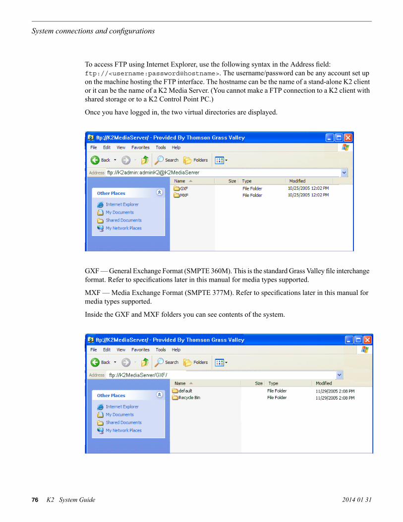
To access FTP using Internet Explorer, use the following syntax in the Address field:ftp://<username:password@hostname>. The username/password can be any account set upon the machine hosting the FTP interface. The hostname can be the name of a stand-alone K2 clientor it can be the name of a K2 Media Server. (You cannot make a FTP connection to a K2 client withshared storage or to a K2 Control Point PC.)
Once you have logged in, the two virtual directories are displayed.
GXF — General Exchange Format (SMPTE 360M). This is the standard Grass Valley file interchangeformat. Refer to specifications later in this manual for media types supported.
MXF — Media Exchange Format (SMPTE 377M). Refer to specifications later in this manual formedia types supported.
Inside the GXF and MXF folders you can see contents of the system.
76 K2 System Guide 2014 01 31
System connections and configurations

The subfolders are organized in typical Windows fashion, with columns denoting the file’s name,size, etc. The Size column refers to the clip duration (in video fields).
You can use Internet Explorer to drag a file from your stand-alone K2 system or K2 Media Serverand drop it in a folder on your PC. You can also drag a file from your PC and drop it in the appropriatefolder on your stand-alone K2 system or K2 Media Server.
Be careful not to mix files from the two types of file interchange formats. GXF files can only betransferred to the GXF folder, and MXF files can only be transferred to the MXF folder. If you tryto drop a clip into the incorrect folder, the transfer fails. For example, clip1.gxf can be droppedinto the K2-MediaSVR/GXF/default/ folder, but not into the K2-MediaSVR/MXF/default/ folder.Related Topics
FTP and media access security on page 73
FTP commands supported
The following table lists the FTP commands that the K2 FTP interface supports.
K2 FTP supportFTP command descriptionFTP command name
SupportedUser NameUSER
SupportedPasswordPASS
Not supportedAccountACCT
SupportedChange working directoryCWD
SupportedChange to parent directoryCDUP
Not supportedStructure mountSMNT
Not supportedReinitializeREIN
SupportedLogoutQUIT
SupportedData portPORT
2014 01 31 K2 System Guide 77
System connections and configurations

K2 FTP supportFTP command descriptionFTP command name
SupportedPassivePASV
SupportedRepresentation typeTYPE
Not supportedFile structureSTRU
Not supportedTransfer modeMODE
SupportedRetrieveRETR
SupportedStoreSTOR
Not supportedStore uniqueSTOU
Not supportedAppend (with create)APPE
Not supportedAllocateALLO
Not supportedRestartREST
SupportedRename FromRNFR
SupportedRename ToRNTO
SupportedAbortABOR
SupportedDeleteDELE
SupportedRemove directoryRMD
SupportedMake directoryMKD
SupportedPrint working directoryPWD
Supported. Reports size innumber of video fields.
ListLIST
SupportedName ListNLST
SupportedSite ParametersSITE
SupportedSystemSYST
Supported. Reports size inBytes.
Size of file (clip)SIZE
SupportedStatusSTAT
SupportedHelpHELP
SupportedNo OperationNOOP
Using FTP on a K2 Nearline SAN
A K2 Nearline SAN is considered an “offline” system, as it has no media database and is not capableof direct playout of media. On this type of system the K2 FTP interface operates in file mode.Therefore, procedures that apply to “online” K2 SANs do not globally apply to the Nearline SAN.This includes procedures for streaming, import, export, and FTP.
78 K2 System Guide 2014 01 31
System connections and configurations

The rules for transferring to/from a K2 Nearline SAN are as follows:
• Transfer files only. Streaming media, as in AppCenter’s Import/Send to | Stream feature, is notsupported.
• K2 media must be transferred to/from the Nearline system as a GXF or MXF file.• Passive FTP mode is supported. You must use this mode for FTP transfers.• In addition to FTP transfers, you can also map shared drives and use basic Windows networking
to move files to/from a Nearline storage system.• You should use the dedicated K2 FTP/streaming network.
Additional information about Nearline FTP is as follows:
• K2 FTP protocol supports clip and bin names in non-English locales (international languages)using UTF-8 character encoding. Refer to specifications for internationalization.
• The Nearline FTP interface operates in file mode so it does not have GXF and MXF folders tosupport format-specific functionality, as does the K2 FTP interface in movie mode for “online”K2 systems. This means the Nearline FTP interface treats all files, including GXF and MXF, asgeneric files with no particular consideration for any file format.
Using reference files
When you create a simple K2 clip on a K2 system, K2 software can create a corresponding referencefile. The reference file is stored in a directory in the clip's folder on the V: drive. You can configurethe software to create QuickTime reference files or no reference files. The following topics provideinformation about reference files on K2 systems.
About QuickTime reference files
The following formats are supported as QuickTime reference files:
• DV• AVC-Intra• XDCAM-EX• XDCAM-HD• XDCAM-HD 422• IMX• Avid DNxHD
The K2 clip must be a simple clip in order to create the reference file. With the QuickTime referencefile you can open the K2 clip with QuickTime tools, such as Final Cut Pro, for playback and editing.For some formats the QuickTime tool does not provide default support, so you must configure thetool as necessary to support the format. The QuickTime tool must be run on another system. Runningthe QuickTime player or other QuickTime tools on the K2 system is not supported. You have optionsfor connections, access, and software to support your workflow requirements.
2014 01 31 K2 System Guide 79
System connections and configurations

Configuring reference file type on a standalone K2 Summit/Solo system
1. In AppCenter, click File | System | Configuration.Configuration Manager opens.
2. In Configuration Manager, click the System tab.3. In Reference Files settings, for the Reference file type setting, select one of the following:
• None — K2 software does not create reference files.• QuickTime — K2 software creates QuickTime reference files.
4. Click OK to apply the setting.5. Restart the standalone K2 Summit/Solo system to put the change into effect.
Configuring reference file type on a K2 SAN system
1. In the K2Config application, for the K2 Media Server with role of file system server, access theFile System Server Configuration page as follows:
• On a SAN that is already configured, in the tree view click File System Server.• On a SAN that is not yet fully configured, work through the Configure K2 Server wizard until
you reach the File System Server Configuration page.
2. On the File System Server Configuration page select one of the following:
• No reference file — K2 software does not create reference files.• QuickTime reference file — K2 software creates QuickTime reference files.
3. Click Check to apply the setting.4. Manage the required K2 Media Server restart as follows:
• On a SAN that is already configured, you must restart the K2 Media Server to put the changeinto effect. Follow the restart procedure appropriate for the basic or redundant K2 SAN.
• On a SAN that is not yet fully configured, continue to work through the Configure K2 Serverwizard. The restart at the end of the configuration process is sufficient.
If a redundant K2 SAN, you must configure similarly and restart both K2 Media Servers with roleof file system server.
MXF Export Type
When importing and exporting MXF the K2 system behaves as follows, in relation to the MXFExport Type setting in K2Config or in K2 AppCenter:
• The MXF Export Type setting applies to all MXF exports on the K2 system. There is one settingfor one K2 system. The K2 system can be a stand-alone K2 Summit/Solo system or a K2 SAN.If a K2 SAN, the one setting applies to the K2 Media Server with role of FTP server that handlesexports for all SAN-attached K2 Summit systems.
80 K2 System Guide 2014 01 31
System connections and configurations

• For export, the K2 system must be set to one of the following MXF Export Types:
• SMPTE 377M• SMPTE 377-1
• By default the K2 system is set to SMPTE 377M.• The SMPTE 377M setting is recommended for compatibility with older systems which do not
support SMPTE 377-1.• The following formats do not support SMPTE 377-1 export. Therefore these formats are always
exported as SMPTE 377M, regardless of the MXF Export Type setting:
• XDCAM HD clips with XDCAM HD/EX/HD422 compatible video• D10 media
• For import, both SMPTE 377M and 377-1 are supported at all times, regardless of the MXFExport Type setting. The MXF Export Type setting affects export only.
•
Configuring MXF Export Type on a standalone K2 Summit/Solo system
1. In AppCenter, click File | System | Configuration.Configuration Manager opens.
2. In Configuration Manager, click the System tab.3. In MXF Export settings, for the MXF Export Type setting, select one of the following:
• 377M: Original SMPTE 377M style. Ensures compatibility with older products.• 377-1: Newer SMPTE 377-1 style.
4. Click OK to apply the setting.5. Restart the standalone K2 Summit/Solo system to put the change into effect.
Configuring MXF Export Type on a K2 SAN system
1. In the K2Config application, for the K2 Media Server with role of FTP server, access the FTPServer Configuration page as follows:
• On a SAN that is already configured, in the tree view click FTP Server.• On a SAN that is not yet fully configured, work through the Configure K2 Server wizard until
you reach the FTP Server Configuration page.
2. On the FTP Server Configuration page select one of the following:
• 377M: Original SMPTE 377M style. Ensures compatibility with older products.• 377-1: Newer SMPTE 377-1 style.
2014 01 31 K2 System Guide 81
System connections and configurations

3. Manage the required K2 Media Server restart as follows:
• On a SAN that is already configured, you must restart the K2 Media Server to put the changeinto effect. Follow the restart procedure appropriate for the basic or redundant K2 SAN.
• On a SAN that is not yet fully configured, continue to work through the Configure K2 Serverwizard. The restart at the end of the configuration process is sufficient.
Quicktime and Final Cut Pro support
You can access K2 media as QuickTime for editing in Final Cut Pro, as explained in the followingtopics.
About connecting to K2 storage with Final Cut Pro
This topic describes the different ways you can access K2 media for editing with Final Cut Pro.
Connection types are as follows:
• iSCSI – This is a connection as a client to an iSCSI K2 SAN. The connection requires a K2 FCPConnect license and supporting software on the Macintosh system. The connection uses the K2SAN's iSCSI Gigabit Ethernet network.
Access methods are as follows:
• Edit-in-place – With this method you edit the K2 media in Final Cut Pro across the networkwhile the media is still in place in K2 storage. You can do this over any connection type.
• File transfer – With this method you transfer (copy) the K2 media to the Macintosh system andthen edit it in Final Cut Pro across the network while the media is still in place in K2 storage.You can do this over any connection type. You can initiate the transfer as file copy over iSCSI,or via FTP.
With all access methods, after you are done editing the K2 media you export it back to K2 storagevia a K2 HotBin.
Software components that support various workflows are as follows:
• K2 FCP Connect – This is a Grass Valley product that supports all connection types for optimalperformance. It is a toolset that must be purchased, installed, licensed, and configured. It includesGV Connect, which is a Final Cut Pro plug-in. GV Connect supports edit-in-place and file transferover iSCSI.
Refer to product release notes for information about connections, access, and software that applyto K2 storage and versions.
82 K2 System Guide 2014 01 31
System connections and configurations

For detailed instructions refer to documentation as follows:
• iSCSI – Refer to the K2 FCP Connect documentation set, which includes the following documents:
• K2 FCP Connect Installation Manual• K2 FCP Connect Release Notes• GV Connect User Manual
Related Topics
About QuickTime reference files on page 79
Operation guidelines
Take the following into consideration as you use Final Cut Pro on K2 storage.
• Do not use the K2 AppCenter "Erase Unused Media" operation on clips that you are accessingon K2 storage.
Export to K2 storage
When exporting media to K2 storage, Final Cut Pro export options must be constrained so that theresulting media is playable on a K2. The exported media must match the frame rate of moviessupported on the K2 system. This is especially important in XDCAM where there are 25, 29.97/30,50 and 59.94/60 rates.
1. Create the Final Cut Pro clip with a single track of video.2. Save the Final Cut Pro clip with a .mov extension.3. Use the Final Cut Pro "Using QuickTime Conversion" method to export the Final Cut Pro clip
as a stream movie to the K2 HotBin.Make sure the frame rate is supported on the K2 system.For material originally recorded on a K2 system, supported frame rates are as follows:
• If you are exporting 1080i material the frame rate must be "Current" or 60 (50 for PAL).• If you are exporting 720p material the frame rate must be "Current" or 60.• If you are exporting 720p material for 1080i conversions the frame rate must be 60 (50 for
PAL).
The HotBin imports the clip into the K2 system as K2 media. As a by-product of the import, the K2system creates a QuickTime reference file for the new K2 media.
About QuickTime import delay
When you copy a file into a K2 HotBin, the HotBin watches for the file to close and the copyoperation to stop, which should indicate the file is complete, before it begins to import the file intoK2 storage. However, Final Cut Pro repeatedly opens and closes any QuickTime file as it exportsthe file, so it is possible that the K2 HotBin can detect a file closed event and begin to import thefile before Final Cut Pro is done. If this occurs, the K2 HotBin import for that file fails.
2014 01 31 K2 System Guide 83
System connections and configurations

To avoid this problem, when you configure a K2 HotBin you can configure the QuickTime importdelay setting. This setting allows you to adjust how long a QuickTime file must be idle (no databeing written to the file) before the HotBin begins to import the file into K2 storage. Therecommended default value is 15 seconds. If you have problems with failed imports and you suspectthat Final Cut Pro is holding on to the file with pauses longer than 15 seconds, you should increasethe QuickTime import delay time and re-try the import. The HotBin process constrains the QuickTimeimport delay range to between 10 and 60 seconds.
Connecting RS-422 K2 Summit/Solo 3G systemYou can control the K2 system with remote control devices and software developed for the K2system that use industry-standard serial protocols: AMP, BVW, and VDCP. Make RS-422 connectionsfor protocol control as illustrated:
!
OK
~AC
C1 C2 C3 C4
USB/1394 100BT/1000BT
GPI
VGAREF. LOOP THROUGH
!
OK
~AC
Channel 1RS-422
Channel 2RS-422
Channel 3RS-422
Channel 4RS-422
Refer to topics in "K2 AppCenter User Manual" to configure the K2 system for remote control.
Connecting RS-422 first generation SummitYou can control the K2 system with remote control devices and software developed for the K2system that use industry-standard serial protocols: AMP, BVW, and VDCP. Make RS-422 connectionsfor protocol control as illustrated:
Channel 1RS-422
Channel 2RS-422
Channel 3RS-422
Channel 4RS-422
Refer to the K2 AppCenter User Manual to configure the K2 system for remote control.Related Topics
About remote control protocols on page 197RS-422 protocol control connections on page 201
84 K2 System Guide 2014 01 31
System connections and configurations

Connecting GPIThe K2 Summit/Solo system provides 12 GPI inputs, and 12 GPI outputs on a single DB-25 rearpanel connector, as illustrated:
!
OK
~AC
C1 C2 C3 C4
USB/1394 100BT/1000BT
GPI
VGAREF. LOOP THROUGH
!
OK
~AC
GPI in/out
K2 Summit 3G system shown. Connection is identical on first generation K2 Summit/Solo system.
Refer to topics in "K2 AppCenter User Manual" for GPI configuration procedures.Related Topics
GPI I/O specifications on page 210GPI I/O connector pinouts on page 254
2014 01 31 K2 System Guide 85
System connections and configurations

86 K2 System Guide 2014 01 31
System connections and configurations

Import/export services
Using the HotBin capture service
This section contains topics about the K2 HotBin Import capture service.
About the HotBin capture service
The functionality of the HotBin service is provided by the Grass Valley Import Service. The HotBinservice provides a way to automate the import of files as clips into the K2 media file system anddatabase. This is similar to what happens when you manually import files one at a time using K2AppCenter import features, except with the HotBin service the files are automatically imported.The HotBin service can import any file or stream type that is supported as a K2 file-based import.
By default, the service does not start automatically. If you have never configured or used the service,it is set to startup type Manual. When you configure the service for the first time, the service is setto startup type Automatic. However, if you upgrade or otherwise re-install your K2 System Software,the service is re-set to startup type Manual. Therefore, you must re-configure the service after K2System Software upgrade/reinstall in order to set the startup type back to Automatic.
There is no Grass Valley license required specifically for the HotBin service.
Before you can use the HotBin service, it must be configured through the K2 Capture Servicesutility. The HotBin service must be configured on the K2 system that receives the imported media.The K2 system that receives the imported media can be a K2 Solo Media Server, a stand-alone K2Summit Production Client, a stand-alone K2 Media Client, or the K2 Media Server with the role ofprimary FTP server on a K2 SAN.
Once configured, the HotBin service monitors a watched folder (a HotBin). The watched folder isa specified source directory on a source PC. The watched folder can be on a stand-alone K2 system,a K2 Media Server, a Windows PC, or a Macintosh. When files are placed in the watched folder,the HotBin service imports them as a clip into the specified destination bin. The destination bin ison the K2 system that receives the imported media and is within that K2 system’s media file systemand database.
The HotBin service automatically creates sub-directories in the watched folder (source directory),described as follows:
• Success — After the HotBin service successfully imports the files in the source directory intothe destination bin on the K2 system, it then moves those files into the Success directory.
• Fail — If the HotBin service can not successfully import the files in the source directory into thedestination bin on the K2 system, it moves the failed files into the Fail directory.
2014 01 31 K2 System Guide 87

• Archive — If there are files in the source directory when the Hot Bin service first starts up, itdoes not attempt to import those files into the K2 system. Instead, it moves those files into theArchive directory. This occurs when you first configure the Hot Bin service, if you manuallystop/start the Hot Bin service, and when you upgrade K2 system software.
Related Topics
K2 Summit Transmission models specifications on page 203
Prerequisites for using the HotBin capture service
Before you can configure and use the P2 Import capture service, the following requirements mustbe satisfied:
• K2 system software must be at version 3.2.56 or higher.
Use topics in this section as appropriate to satisfy prerequisites.
Considerations for using the HotBin capture service
When you are configuring and using the K2 HotBin capture service, bear in mind the followingconsiderations:
• You must be logged in with administrator privileges on the K2 system as well as having theappropriate security permissions to access the watched folder or bin.
• If you have multiple source folders (for import) or destination folders (for export) on externalsystems, use the same user account for all capture service access to all systems.
• If using the capture service on a K2 SAN, the K2 Capture Services utility and the import watchedfolder must be on a K2 Media Server that is also an FTP server. If your K2 SAN has multipleFTP servers, the utility and folder must be on the primary FTP server.
• It is recommended that you keep the source directory and destination bin located on the local V:drive, which is their default location.
• Do not configure the root of C:\ as the source directory or any other location with files that mustbe retained. When the HotBin service first starts up it removes files in the source directory.
• If you require that the source directory and destination bin be on different systems, system clocksmust be synchronized. The Cleanup Frequency function depends on accurate system clocks.
• If you specify a destination bin name that does not yet exist, the K2 system creates it when filesare transferred to it.
• Imports are serialized. For example, if you drop two clips into the watched folder for import, thecapture service does not queue the second clip for import until the first clip is imported. This isdifferent than the ordinary K2 transfer process.
• Capture service imports are serialized with other K2 transfers. For example, if fourteen itemsare already queued up from ordinary K2 transfers, and you drop content into the watched folderfor import, the import triggered by the capture service becomes the fifteenth clip in the transferqueue.
• After the capture service imports media into K2 media storage successfully, the capture serviceimmediately deletes the original media files from the watched folder. If the import fails, theoriginal media files are retained in the watched folder for the number of days specified as theCleanup Frequency.
88 K2 System Guide 2014 01 31
Import/export services

• The “Cleanup Frequency” (purge) feature deletes files in the Success sub-directory and in theFail sub-directory. It does not delete files in the Archive sub-directory.
• Files in the Success, Fail, and Archive sub-directories are “hidden” files in Windows Explorer.To see these files you must select Show Hidden Files in the Windows Explorer Folder Optionsdialog box.
Grass Valley recommends that you use the HotBin service as demonstrated in the following diagram.
K2 system (stand-alone)
K2 client (shared storage)
1
On the K2 system,make thesource directorya shared folder.
2
Sourcedirectory
Destination bin
Mappeddrive
On your system,map a driveto the shared folder.
3
Transfer media filesfrom your system tothe shared folderon the mapped drive.
Transfer media filesfrom your system tothe shared folderon the mapped drive.
4The HotBin serviceautomaticallyimports files to thedestination binon the K2 system.
1 2 3
4The HotBin serviceautomaticallyimports files to thedestination binon the K2 System.
Source directory
Destination bin
Using the HotBin service with a standalone K2 system
Using the HotBin service with a K2 SAN
On the K2 Media Server,make thesource directorya shared folder.
On your system,map a driveto the shared folder.
K2 Media Server
Mappeddrive
While not preferred, you can also use the HotBin service if the source directory is on another system.The following table lists the requirements for accessing a source directory located on various operatingsystems.
2014 01 31 K2 System Guide 89
Import/export services

...and the source directory is on a shared folder on a mapped drive, youneed:
If your source directoryis on:
• Administrator privileges for the K2 system• A user account with log-in service rights for your system
Another Windowssystem
• Privileges as listed above.• The identical user name and password on both systems. For example,
if you have a Macintosh user named Jane, you would need to have auser named Jane on your Windows system with the same password.From the Windows Control Panel, select Administrator Tools | LocalSecurity Policy | User Rights Assignment | Log on as service and clickAdd New User.
Macintosh operatingsystem
Configuring the HotBin Capture Service
NOTE: Once configured, the service deletes files in the watched folder or bin (source) that areolder than the specified cleanup frequency.
1. From the Start menu, access the All Programs menu and select Grass Valley | K2 Capture Services.The K2 Capture Services utility dialog box is displayed.
2. Click the HotBinImport tab.
3. Select Use HotBinImport.
90 K2 System Guide 2014 01 31
Import/export services

4. To retain the current version of a clip at the destination that is named the same as a clip you areimporting, select If a clip exists, import and generate a new name.The Hotbin service increments the file name of the imported clip so it does not overwrite the clipat the destination.
5. Enter the paths to the source directory and destination bin. If the source directory does notcurrently exist, it will automatically be created.NOTE: Do not configure the source directory to be a location with files that must be retained.When the HotBin service first starts up it removes files in the source directory.
6. For Check Frequency, it is recommended that you accept the default value. This value specifieshow often you want the capture service to check the source directory for new files.
7. For the Cleanup Frequency, it is recommended that you accept the default value. This valuespecifies the maximum age of files in the source directory. The capture service deletes files thatare older than this age.
8. If the source directory is not on the local K2 system, a User Account dialog box displays. Enterthe user information that you use to access the source directory. If part of a domain, enter thedomain name.
9. If necessary, configure QuickTime Import Delay.This setting adjusts how long a QuickTime file must be idle (no data being written to the file)before the HotBin begins to import the file into K2 storage. The recommended setting is 15seconds.
10. When your capture service settings are complete, click Apply.If prompted, restart the K2 system.
The HotBin service checks the source directory for files. If files are present, the HotBin servicemoves them to the Archive sub-directory. It does not import the files into the destination bin on theK2 system.
Place files in the source directory to trigger the Hot Bin import processes.
HotBin capture service components
The following table describes the components that support K2 HotBin capture service functionality.
DescriptionName
This is the service that provides the functionality for a K2 captureservice. It is the service that automatically creates the K2 clipfrom the media files in the watched folder (source directory) andputs the K2 clip in the K2 media storage (destination bin).
Grass Valley Import Service
Configures K2 capture services.K2 Capture Services utility
This is the watched folder. It is a standard file system directory.When media files are placed in this directory, the capture serviceautomatically creates a K2 clip in the K2 media storage. Bydefault, the location of the source directory is V:/IMPORTS.
Source directory
Determines how often (in seconds) the watched folder is checkedfor new files.
Check frequency
2014 01 31 K2 System Guide 91
Import/export services

DescriptionName
Determines how long (in days) a file remains in the watchedfolder. A file with a file-creation date older than the specifiednumber of days is deleted.
Cleanup frequency
The clip bin in the K2 media storage that receives the K2 clipcreated by the capture service. The destination bin is in the K2media database and appears in AppCenter as a media bin. Bydefault, its location is V:/IMPORTS.
Destination bin
Using the XML Import capture service
This section contains topics about the K2 XML Import capture service.
About the XML Import capture service
The K2 XML Import capture service provides a way to have media automatically imported into aK2 system when it is pushed to the K2 system by a third party application. The XML Import captureservice has a watched folder. The watched folder is a standard file system directory that can berecognized by the Windows operating system. You transfer the media to the directory using thethird party application.
By default, the service does not start automatically. If you have never configured or used the service,it is set to startup type Manual. When you configure the service for the first time, the service is setto startup type Automatic. However, if you upgrade or otherwise re-install your K2 System Software,the service is re-set to startup type Manual. Therefore, you must re-configure the service after K2System Software upgrade/reinstall in order to set the startup type back to Automatic.
After all the media files are finished being transferred to the watched folder, the third party applicationthen transfers an XML file to the watched folder. This XML file defines the media files and specifieshow they are to be assembled to create a K2 clip. When the XML file finishes transferring to thewatched folder, the capture service goes into action and validates the XML file to make sure it hasthe proper structure. If the XML file is valid, the capture service then does the necessary processingto create the clip in the K2 media storage. The media is then available as a K2 clip, ready for playout.
The K2 XML Import capture service and its watched folder must be on a K2 system that hosts theK2 FTP interface, as follows:
• Stand-alone K2 system— When media files and the XML file are pushed to the watched folder,the capture service creates a K2 clip in the internal storage or direct-connect media storage ofthe K2 system. The watched folder must be on the K2 system’s V: drive.
• K2 Media Server with role of FTP server — When media files and the XML file are pushed tothe watched folder, the capture service creates a K2 clip in the shared media storage of the K2SAN. The watched folder must be on the K2 Media Server’s V: drive.
92 K2 System Guide 2014 01 31
Import/export services

Prerequisites for using the XML Import capture service
Before you can configure and use the XML Import capture service, the following requirements mustbe satisfied:
• K2 system software must be at a version that supports the XML Import capture service. Referto K2 Release Notes for information on XML Import capture service version compatibility.
• The K2 XML Import capture service must be licensed on the stand-alone K2 system or K2 MediaServer. This is a Grass Valley software license.
• The application that pushes the media files and XML file to the watched folder must providevalid files according to K2 XML Import capture service requirements. Developers of applicationscan contact Grass Valley Developer Support for more information
Use topics in this section as appropriate to satisfy prerequisites.
Considerations for using the XML import capture service
When you are configuring and using the K2 XML Import capture service, bear in mind the followingconsiderations:
• You must be logged in with administrator privileges on the K2 system as well as having theappropriate security permissions to access the watched folder or bin.
• If using the capture service on a K2 SAN, the K2 Capture Services utility and the import watchedfolder must be on a K2 Media Server that is also an FTP server. If your K2 SAN has multipleFTP servers, the utility and folder must be on the primary FTP server.
• After the capture service imports media into K2 media storage successfully, the capture serviceimmediately deletes the original media files from the watched folder. If the import fails, theoriginal media files are retained in the watched folder for the number of days specified as theCleanup Frequency.
• The transfer of the media files, then the XML file, must be 100% complete before the K2 XMLImport capture service begins to create the clip in K2 media storage.
Configuring the XML Import Capture Service
NOTE: Once configured, the service deletes files in the watched folder or bin (source) that areolder than the specified cleanup frequency.
1. From the Start menu, access the All Programs menu and select Grass Valley | K2 Capture Services.The K2 Capture Services utility dialog box is displayed.
2014 01 31 K2 System Guide 93
Import/export services

2. Click the XML Import tab.
3. Select UseXMLImport.If you have not yet licensed the XML Import capture service, a “…start the process of getting alicense now?” message appears. Follow on-screen instructions to obtain a license. After licensing,restart the K2 Capture Services utility and continue with this procedure.
4. Enter the paths to the source directory and destination bin, which are defined as follows:
• Source Directory — This is the watched folder. It is a standard file system directory. It mustbe on the K2 system’s V: drive. When valid media is placed in this directory, the captureservice automatically creates a K2 clip in the K2 media storage.
• Destination Bin — The clip bin in the K2 media storage that receives the media processedby the capture service. The destination bin is in the K2 media database and it appears inAppCenter as a media bin. The bin must be on the K2 system’s V: drive. If you specify adestination bin name that does not yet exist, the K2 system creates it when the K2 clip iscreated.
5. For Check Frequency, it is recommended that you accept the default value. This value specifieshow often you want the capture service to check the source directory for new files.
6. For the Cleanup Frequency, it is recommended that you accept the default value. This valuespecifies the maximum age of files in the source directory. The capture service deletes files thatare older than this age.
7. When your capture service settings are complete, click Apply.If prompted, restart the K2 system.
The service checks the source directory for any files that are beyond the specified cleanup age anddeletes them from the directory.
94 K2 System Guide 2014 01 31
Import/export services

Testing the XML Import Capture Service
1. Place media files into the watched folder.2. On the K2 System, open Windows Explorer, browse to the watched folder and verify that files
have completed the transfer. The transfer must be 100% complete before the capture servicetriggers the processes to create the K2 clip.
3. Place a valid XML file into the watched folder.4. On the K2 System, open Windows Explorer, browse to the watched folder and verify that XML
file has completed the transfer. The transfer must be 100% complete before the K2 XML Importcapture service triggers the processes to create the K2 clip.
5. After the K2 clip is created, verify that the media appears in the destination bin.6. Play to verify success.
XML Import capture service components
The following table describes the components that support K2 XML Import capture servicefunctionality.
DescriptionName
This is the service that provides the functionality for a K2 captureservice. It is the service that automatically creates the K2 clipfrom the media files in the watched folder (source directory) andputs the K2 clip in the K2 media storage (destination bin).
Grass Valley Import Service
Configures K2 capture services.K2 Capture Services utility
This is the watched folder. It is a standard file system directory.When media files are placed in this directory, the capture serviceautomatically creates a K2 clip in the K2 media storage. Bydefault, the location of the source directory is V:\XmlImport.
Source directory
Determines how often (in seconds) the watched folder is checkedfor new files.
Check frequency
Determines how long (in days) a file remains in the watchedfolder. A file with a file-creation date older than the specifiednumber of days is deleted.
Cleanup frequency
The clip bin in the K2 media storage that receives the K2 clipcreated by the capture service. The destination bin is in the K2media database and appears in AppCenter as a media bin. Bydefault, its location is V:\XmlImport.
Destination bin
Using the P2 capture service
This section contains topics about the K2 P2 Import capture service.
2014 01 31 K2 System Guide 95
Import/export services

About the P2 capture service
The K2 P2 Import capture service provides a way to have P2 media automatically imported into aK2 system. The P2 Import capture service has a watched folder. The watched folder is a standardfile system directory that can be recognized by the Windows operating system. You transfer themedia to the directory and it is imported into the K2 system.
By default, the service does not start automatically. If you have never configured or used the service,it is set to startup type Manual. When you configure the service for the first time, the service is setto startup type Automatic. However, if you upgrade or otherwise re-install your K2 System Software,the service is re-set to startup type Manual. Therefore, you must re-configure the service after K2System Software upgrade/reinstall in order to set the startup type back to Automatic.
The watched folder receives the nested directories that define P2 media for one clip or multipleclips. After all the directories/files are finished being transferred to the watched folder, the captureservice goes into action and validates the P2 media to make sure it has the proper structure. If theP2 file is valid, the capture service then does the necessary processing to create the clip in the K2media storage. The media is then available as a K2 clip, ready for playout.
The K2 P2 Import capture service and its watched folder must be on a K2 system that hosts the K2FTP interface, as follows:
• Stand-alone K2 system — When media files and the P2 files are pushed to the watched folder,the capture service creates a K2 clip in the internal storage or direct-connect media storage ofthe K2 system. The watched folder must be on the K2 system’s V: drive.
• K2 Media Server with role of FTP server — When media files are pushed to the watched folder,the capture service creates a K2 clip in the shared media storage of the K2 SAN. The watchedfolder must be on the K2 Media Server’s V: drive.
Prerequisites for using the P2 capture service
Before you can configure and use the P2 Import capture service, the following requirements mustbe satisfied:
• The K2 system must support AVC-Intra. This requires that the AVC-Intra codec card be installed.• K2 system software must be at a version that supports the P2 Import capture service. Refer to
K2 Release Notes for information on P2 Import capture service version compatibility.• The K2 P2 Import capture service must be licensed on the stand-alone K2 system or K2 Media
Server. This is a Grass Valley software license.• The Panasonic storage device that is the source of the P2 media must be on a separate PC and
all Panasonic drivers must exist on that PC.• The directories/file transferred to the watched folder must be valid files according to P2
requirements.
Use topics in this section as appropriate to satisfy prerequisites.
96 K2 System Guide 2014 01 31
Import/export services

Considerations for using the P2 capture service
When you are configuring and using the K2 P2 Import capture service, bear in mind the followingconsiderations:
• You must be logged in with administrator privileges on the K2 system as well as having theappropriate security permissions to access the watched folder or bin.
• If you have multiple source folders (for import) or destination folders (for export) on externalsystems, use the same user account for all capture service access to all systems.
• If using the capture service on a K2 SAN, the K2 Capture Services utility and the import watchedfolder must be on a K2 Media Server that is also an FTP server. If your K2 SAN has multipleFTP servers, the utility and folder must be on the primary FTP server.
• You can share the K2 V: drive, so that the Panasonic storage device can access via CIFS.• P2 content can be dragged/dropped onto the V: drive watch folder from a Panasonic storage
device.• After the capture service imports media into K2 media storage successfully, the capture service
immediately deletes the original media files from the watched folder. If the import fails, theoriginal media files are retained in the watched folder for the number of days specified as theCleanup Frequency.
• The transfer of the directories/files must be 100% complete before the capture service begins tocreate the clip in K2 media storage.
• P2 content is imported as follows:
• A simple clip with striped timecode is created.• Video (AVC-Intra and DV) track is imported and added to the clip• Audio tracks are imported and added to the clip• There is no P2 Import of metadata into the clip
Configuring the P2 Capture Service
NOTE: Once configured, the service deletes files in the watched folder or bin (source) that areolder than the specified cleanup frequency.
1. From the Start menu, access the All Programs menu and select Grass Valley | K2 Capture Services.The K2 Capture Services utility dialog box is displayed.
2014 01 31 K2 System Guide 97
Import/export services

2. Click the P2 Import tab.
3. Select Use P2Import.If you have not yet licensed the P2 Import capture service, a “…start the process of getting alicense now?” message appears. Follow on-screen instructions to obtain a license. After licensing,restart the K2 Capture Services utility and continue with this procedure.
4. To retain the current version of a clip at the destination that is named the same as a clip you areimporting, select If a clip exists, import and generate a new name.The Hotbin service increments the file name of the imported clip so it does not overwrite the clipat the destination.
5. Enter the paths to the source directory and destination bin, which are defined as follows:
• Source Directory — This is the watched folder. It is a standard file system directory. It mustbe on the K2 system’s V: drive. When valid media is placed in this directory, the captureservice automatically creates a K2 clip in the K2 media storage.
• Destination Bin — The clip bin in the K2 media storage that receives the media processedby the capture service. The destination bin is in the K2 media database and it appears inAppCenter as a media bin. The bin must be on the K2 system’s V: drive. If you specify adestination bin name that does not yet exist, the K2 system creates it when the K2 clip iscreated.
6. For Check Frequency, it is recommended that you accept the default value. This value specifieshow often you want the capture service to check the source directory for new files.
7. For the Cleanup Frequency, it is recommended that you accept the default value. This valuespecifies the maximum age of files in the source directory. The capture service deletes files thatare older than this age.
8. When your capture service settings are complete, click Apply.If prompted, restart the K2 system.
98 K2 System Guide 2014 01 31
Import/export services
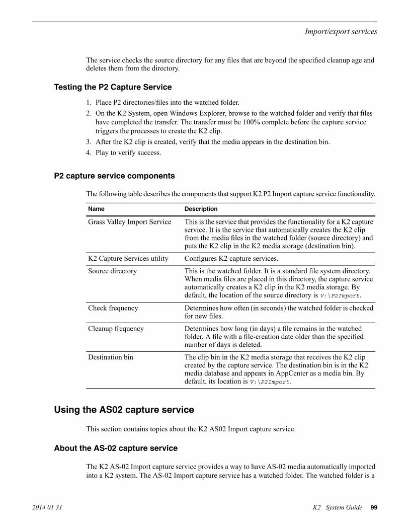
The service checks the source directory for any files that are beyond the specified cleanup age anddeletes them from the directory.
Testing the P2 Capture Service
1. Place P2 directories/files into the watched folder.2. On the K2 System, open Windows Explorer, browse to the watched folder and verify that files
have completed the transfer. The transfer must be 100% complete before the capture servicetriggers the processes to create the K2 clip.
3. After the K2 clip is created, verify that the media appears in the destination bin.4. Play to verify success.
P2 capture service components
The following table describes the components that support K2 P2 Import capture service functionality.
DescriptionName
This is the service that provides the functionality for a K2 captureservice. It is the service that automatically creates the K2 clipfrom the media files in the watched folder (source directory) andputs the K2 clip in the K2 media storage (destination bin).
Grass Valley Import Service
Configures K2 capture services.K2 Capture Services utility
This is the watched folder. It is a standard file system directory.When media files are placed in this directory, the capture serviceautomatically creates a K2 clip in the K2 media storage. Bydefault, the location of the source directory is V:\P2Import.
Source directory
Determines how often (in seconds) the watched folder is checkedfor new files.
Check frequency
Determines how long (in days) a file remains in the watchedfolder. A file with a file-creation date older than the specifiednumber of days is deleted.
Cleanup frequency
The clip bin in the K2 media storage that receives the K2 clipcreated by the capture service. The destination bin is in the K2media database and appears in AppCenter as a media bin. Bydefault, its location is V:\P2Import.
Destination bin
Using the AS02 capture service
This section contains topics about the K2 AS02 Import capture service.
About the AS-02 capture service
The K2 AS-02 Import capture service provides a way to have AS-02 media automatically importedinto a K2 system. The AS-02 Import capture service has a watched folder. The watched folder is a
2014 01 31 K2 System Guide 99
Import/export services

standard file system directory that can be recognized by the Windows operating system. You transferthe media to the directory and it is imported into the K2 system.
By default, the service does not start automatically. If you have never configured or used the service,it is set to startup type Manual. When you configure the service for the first time, the service is setto startup type Automatic. However, if you upgrade or otherwise re-install your K2 System Software,the service is re-set to startup type Manual. Therefore, you must re-configure the service after K2System Software upgrade/reinstall in order to set the startup type back to Automatic.
The watched folder receives the nested directories that define AS-02 media. After all thedirectories/files are finished being transferred to the watched folder, the capture service goes intoaction and validates the AS-02 media to make sure it has the proper structure. If the AS-02 file isvalid, the capture service then does the necessary processing to create the clip in the K2 mediastorage. The media is then available as a K2 clip, ready for playout.
The K2 AS-02 Import capture service and its watched folder must be on a K2 system that hosts theK2 FTP interface, as follows:
• Stand-alone K2 system — When media files and the AS-02 files are pushed to the watched folder,the capture service creates a K2 clip in the internal storage or direct-connect media storage ofthe K2 system. The watched folder must be on the K2 system’s V: drive.
• K2 Media Server with role of FTP server — When media files are pushed to the watched folder,the capture service creates a K2 clip in the shared media storage of the K2 SAN. The watchedfolder must be on the K2 Media Server’s V: drive.
Related Topics
AMWA AS-02 interchange on page 235
Prerequisites for using the AS-02 capture service
Before you can configure and use the AS-02 Import capture service, the following requirementsmust be satisfied:
• K2 system software must be at a version that supports the AS-02 Import capture service. Referto K2 Release Notes for information on AS-02 Import capture service version compatibility.
• K2 Extended File Services must be licensed on the stand-alone K2 system or K2 Media Server.This is a Grass Valley software license.
• The directories/file transferred to the watched folder must be valid files according to AS-02requirements.
Use topics in this section as appropriate to satisfy prerequisites.Related Topics
AMWA AS-02 interchange on page 235
100 K2 System Guide 2014 01 31
Import/export services

Considerations for using the AS-02 capture service
When you are configuring and using the K2 AS-02 Import capture service, bear in mind the followingconsiderations:
• You must be logged in with administrator privileges on the K2 system as well as having theappropriate security permissions to access the watched folder or bin.
• If you have multiple source folders (for import) or destination folders (for export) on externalsystems, use the same user account for all capture service access to all systems.
• If using the capture service on a K2 SAN, the K2 Capture Services utility and the import watchedfolder must be on a K2 Media Server that is also an FTP server. If your K2 SAN has multipleFTP servers, the utility and folder must be on the primary FTP server.
• After the capture service imports media into K2 media storage successfully, the capture serviceimmediately deletes the original media files from the watched folder. If the import fails, theoriginal media files are retained in the watched folder for the number of days specified as theCleanup Frequency.
• The transfer of the directories/files must be 100% complete before the capture service begins tocreate the clip in K2 media storage.
• AS-02 content is imported as follows:
• A simple clip with striped timecode is created.• Audio tracks are imported and added to the clip• MXF descriptive metadata in the version file and the essence files are not preserved
Related Topics
AMWA AS-02 interchange on page 235
Configuring the AS-02 Capture Service
NOTE: Once configured, the service deletes files in the watched folder or bin (source) that areolder than the specified cleanup frequency.
1. From the Start menu, access the All Programs menu and select Grass Valley | K2 Capture Services.The K2 Capture Services utility dialog box is displayed.
2014 01 31 K2 System Guide 101
Import/export services
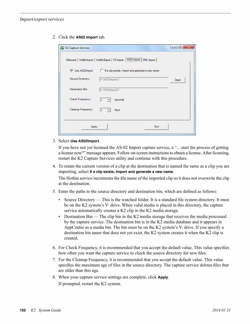
2. Click the AS02 Import tab.
3. Select Use AS02Import.If you have not yet licensed the AS-02 Import capture service, a “…start the process of gettinga license now?” message appears. Follow on-screen instructions to obtain a license. After licensing,restart the K2 Capture Services utility and continue with this procedure.
4. To retain the current version of a clip at the destination that is named the same as a clip you areimporting, select If a clip exists, import and generate a new name.The Hotbin service increments the file name of the imported clip so it does not overwrite the clipat the destination.
5. Enter the paths to the source directory and destination bin, which are defined as follows:
• Source Directory — This is the watched folder. It is a standard file system directory. It mustbe on the K2 system’s V: drive. When valid media is placed in this directory, the captureservice automatically creates a K2 clip in the K2 media storage.
• Destination Bin — The clip bin in the K2 media storage that receives the media processedby the capture service. The destination bin is in the K2 media database and it appears inAppCenter as a media bin. The bin must be on the K2 system’s V: drive. If you specify adestination bin name that does not yet exist, the K2 system creates it when the K2 clip iscreated.
6. For Check Frequency, it is recommended that you accept the default value. This value specifieshow often you want the capture service to check the source directory for new files.
7. For the Cleanup Frequency, it is recommended that you accept the default value. This valuespecifies the maximum age of files in the source directory. The capture service deletes files thatare older than this age.
8. When your capture service settings are complete, click Apply.If prompted, restart the K2 system.
102 K2 System Guide 2014 01 31
Import/export services

The service checks the source directory for any files that are beyond the specified cleanup age anddeletes them from the directory.Related Topics
AMWA AS-02 interchange on page 235
Testing the AS-02 Capture Service
1. Place AS-02 directories/files into the watched folder.2. On the K2 System, open Windows Explorer, browse to the watched folder and verify that files
have completed the transfer. The transfer must be 100% complete before the capture servicetriggers the processes to create the K2 clip.
3. After the K2 clip is created, verify that the media appears in the destination bin.4. Play to verify success.
Related Topics
AMWA AS-02 interchange on page 235
AS-02 capture service components
The following table describes the components that support K2 AS-02 Import capture servicefunctionality.
DescriptionName
This is the service that provides the functionality for a K2 captureservice. It is the service that automatically creates the K2 clipfrom the media files in the watched folder (source directory) andputs the K2 clip in the K2 media storage (destination bin).
Grass Valley Import Service
Configures K2 capture services.K2 Capture Services utility
This is the watched folder. It is a standard file system directory.When media files are placed in this directory, the capture serviceautomatically creates a K2 clip in the K2 media storage.
Source directory
Determines how often (inseconds) the watched folder ischecked for new files.
Determines how long (in days) a file remains in the watchedfolder. A file with a file-creation date older than the specifiednumber of days is deleted.
Cleanup frequency
The clip bin in the K2 media storage that receives the K2 clipcreated by the capture service. The destination bin is in the K2media database and appears in AppCenter as a media bin.
Destination bin
Related Topics
AMWA AS-02 interchange on page 235
2014 01 31 K2 System Guide 103
Import/export services

Using the Export capture service
This section contains topics about the K2 Export capture service.
About the Export capture service
The Export capture service provides a way to have media automatically exported from a K2 system.The capture service has a watched bin. The watched bin is a K2 storage system bin. You place themedia in the bin and it is exported from the K2 system.
By default, the service does not start automatically. If you have never configured or used the service,it is set to startup type Manual. When you configure the service for the first time, the service is setto startup type Automatic. However, if you upgrade or otherwise re-install your K2 System Software,the service is re-set to startup type Manual. Therefore, you must re-configure the service after K2System Software upgrade/reinstall in order to set the startup type back to Automatic.
You configure the watched bin to export the K2 media as your desired clip format. After you placethe K2 clip in the watched bin, the capture service goes into action and validates the media to makesure it has the proper structure for the desired file format. If it is valid, the capture service then doesthe necessary processing to export the clip to the destination folder.
The Export capture service and its watched bin must be on a K2 system that hosts the K2 FTPinterface, as follows:
• Stand-alone K2 system — When you place a K2 clip in the watched bin, the capture serviceexports the clip from the internal storage or direct-connect media storage of the K2 system. Thewatched bin must be on the K2 system’s V: drive.
• K2 Media Server with role of FTP server — When you place a K2 clip in the watched bin, thecapture service exports the clip from the shared media storage of the K2 SAN. The watched binmust be on the K2 Media Server’s V: drive.
Prerequisites for using the Export capture service
Before you can configure and use the Export capture service, the following requirements must besatisfied:
• The K2 system must support the clip format you plan to export. This could require specifichardware and/or licenses.
• K2 system software must be at a version that supports the Export capture service. Refer to K2Release Notes for information on Export capture service version compatibility.
• The capture service must be licensed on the stand-alone K2 system or K2 Media Server. This isa Grass Valley software license.
Use topics in this section as appropriate to satisfy prerequisites.
104 K2 System Guide 2014 01 31
Import/export services
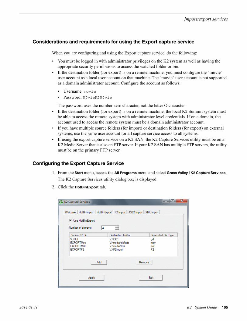
Considerations and requirements for using the Export capture service
When you are configuring and using the Export capture service, do the following:
• You must be logged in with administrator privileges on the K2 system as well as having theappropriate security permissions to access the watched folder or bin.
• If the destination folder (for export) is on a remote machine, you must configure the "movie"user account as a local user account on that machine. The "movie" user account is not supportedas a domain administrator account. Configure the account as follows:
• Username: movie• Password: M0vieK2M0vie
The password uses the number zero character, not the letter O character.• If the destination folder (for export) is on a remote machine, the local K2 Summit system must
be able to access the remote system with administrator level credentials. If on a domain, theaccount used to access the remote system must be a domain administrator account.
• If you have multiple source folders (for import) or destination folders (for export) on externalsystems, use the same user account for all capture service access to all systems.
• If using the export capture service on a K2 SAN, the K2 Capture Services utility must be on aK2 Media Server that is also an FTP server. If your K2 SAN has multiple FTP servers, the utilitymust be on the primary FTP server.
Configuring the Export Capture Service
1. From the Start menu, access the All Programs menu and select Grass Valley | K2 Capture Services.The K2 Capture Services utility dialog box is displayed.
2. Click the HotBinExport tab.
2014 01 31 K2 System Guide 105
Import/export services

3. Select Use HotBinExport.If you have not yet licensed the HotBin Export capture service, a “…start the process of gettinga license now?” message appears. Follow on-screen instructions to obtain a license. After licensing,restart the K2 Capture Services utility and continue with this procedure.
4. Select the number of streams.Exports run serially. If you select one stream, only one export can occur at a time. If you selectmultiple streams, multiple exports can occur at one time.
5. Click Add.The Export Rule dialog box opens.
6. Configure as follows:
• Source K2 Bin Name — Required. This is the watched bin. The bin must be on the K2 system’sV: drive. It must be in the K2 media database and appears in AppCenter as a media bin. Whenvalid clips are placed in this bin, the HotBin Export capture service automatically exports theclips.
• Include Sub-Bins — Optional. When selected, clips are exported if they are in a bin nestedinside the Source K2 Bin.
• Rule — Do not configure this field. Leave the default value as it is.• Destination Folder Path — Required. This is a standard file system directory. It receives the
files/directories exported by the Export capture service. If you specify a destination folderthat does not yet exist, the K2 system creates it when exporting. If the destination folder isnot on the local K2 system, you are prompted to enter user account credentials to access thesource directory. You must enter user account credentials that have administrator levelprivileges on the remote system. If part of a domain, the user account must be a domainadministrator account. When you enter a domain account, you must enter the domain name.NOTE: You must use the same user account for all capture service access to all systems.
• File Type — Required. Select the file format in which K2 clips are exported.• Option — Do not configure this field. Leave the default value as it is.
106 K2 System Guide 2014 01 31
Import/export services

7. Click OK to save settings and close the Export Rule dialog box.8. Repeat previous steps to add additional Export HotBins.
Testing the Export Capture Service
1. Place the clips to export into the watched bin.2. Verify that the media appears in the destination.3. Play to verify success.
Export capture service components
The following table describes the components that support Export capture service functionality.
DescriptionName
This is the service that provides the functionality for the captureservice. It is the service that automatically exports K2 clips fromthe K2 media storage.
Grass Valley Import Service
Configures K2 capture services.K2 Capture Services utility
This is the watched bin. It is a bin in K2 media storage. Whenfiles are placed in this directory, the capture service automaticallyexports them from K2 media storage.
Source K2 bin
The folder that receives the files exported from the K2 mediastorage.
Destination folder
Licensing K2 capture service softwareLicensing is required for K2 capture service software as follows:
• To use the XML Import capture service, you must obtain a XML Import capture service licensefrom Grass Valley.
• To use the P2 Import capture service, you must obtain a P2 Import capture service license fromGrass Valley.
• To use the Export capture service, you must obtain an Export capture service license from GrassValley.
Licenses are requested through the K2 License Wizard and managed through the SabreTooth LicenseManager, which are installed with K2 system software.
1. To start the licensing process, open the K2 Capture Services utility and on the tab for your captureservice, select the “Use…” checkbox.If you do not yet have a license, a “…start the process of getting a license now?” message appears.
2. Click Yes and OK to open the K2 License Wizard for the type of license. Refer to K2 ReleaseNotes for procedures and information on obtaining and managing licenses.
2014 01 31 K2 System Guide 107
Import/export services

PitchBlue workflow considerations
The K2 Summit system supports the H.264 format used in the PitchBlue workflow. However, youmust consider the intended PitchBlue workflow when using this H.264 media, as it is not supportedfor general purpose use outside of the PitchBlue workflow.
The K2 Summit system ingests the PitchBlue material without any error correction. The materialoften has anomalies, such as a broken last frame, that the K2 Summit system accepts as-is. WhenPitchBlue plays out this material under VDCP automation control, it plays the known-good materialonly. PitchBlue determines where the anomalies exist and makes sure that they are not played out.In this way PitchBlue avoids the errors that would otherwise occur if the material were used forgeneral purpose playout without PitchBlue control.
Therefore, you must adhere to the complete PitchBlue workflow from ingest through playout forall PitchBlue material. Do not attempt to play out PitchBlue material except as part of the prescribedPitchBlue workflow. Playing out PitchBlue material in any other way can cause errors.
Pinnacle support
The K2 system can automatically convert Pinnacle material into K2 clips as part of a FTP transferor a HotBin import, as described in the topics in this section.
Pinnacle material that can be converted
A Pinnacle clip is stored as a folder on a Pinnacle MediaStream server. The folder structure for itsMPEG program/system stream based content is as follows:
<folder> clipname <file> header (contains Pinnacle clip metadata) <file> ft (Pinnacle version of “Frame Index Table”) <file> info (File used to hold automation specific data. Not used by Pinnacle.) <file> std (The MPEG program or system stream - essence/media)
You have the following options for the Pinnacle material to convert:
• Convert only the media essence (the std file).• Convert the metadata along with the media essence.
Pinnacle import mechanisms
You have the following options for import/transfer mechanisms:
• K2 HotBin import — This method converts only the media essence. It does not convert thePinnacle clip metadata. You drop the Pinnacle clip’s std file into a K2 HotBin. Then the K2HotBin process imports, converts, and creates a K2 clip. The K2 clip is available for playoutwhen the process is complete.
108 K2 System Guide 2014 01 31
Import/export services

• K2 FTP import — This method converts only the media essence. It does not convert the Pinnacleclip metadata. Your third-party FTP client connects to the K2 FTP server as a normal K2 FTPsession and puts the Pinnacle clip’s std file.
• Pinnacle emulation K2 FTP import — This method converts the Pinnacle clip metadata alongwith the media essence. Your third-party automation vendor or FTP client connects to the K2FTP server with the Pinnacle specific login, creates a new directory, and puts the Pinnacle clipfiles in the new directory. The K2 FTP server creates a corresponding K2 clip. The K2 clip isavailable for playout while the content is being transferred. The K2 clip contains timecode, markin/out points, and other metadata as defined by the Pinnacle clip metadata.
Enabling Pinnacle import
Before you import your Pinnacle material, familiarize yourself with the configuration options in thefollowing procedure.
1. To import Pinnacle material, create the following registry value:
HKEY_LOCAL_MACHINE\Software\Grass Valley Group\StreamingREG_DWORD “ImportPinnacleStreams” = 1
Without this registry value, the K2 system does not handle the import correctly.
2. Do one of the following:
• If do not want to import captions and timecode from your Pinnacle material, skip the remainderof this procedure. No further configuration is necessary.
• If you want to import captions and timecode from your Pinnacle material, continue with thisprocedure. Read each step carefully and proceed only if you are sure that your Pinnaclematerial is suitable.
3. To optionally import VITC from Pinnacle clips, proceed with this step as appropriate.
• If you know that VITC was not recorded on your Pinnacle material in the Pinnacle-privateuncompressed VBI data, skip to the next step. Do not create a registry value.
• If you know that your Pinnacle material was recorded with VITC as Pinnacle-privateuncompressed VBI lines and you want to preserve this timecode when you import the contentinto the K2 system, then create the following registry key:
HKEY_LOCAL_MACHINE\Software\Grass Valley Group\StreamingREG_DWORD “ExtractPinnacleVitc” = 1
This instructs the K2 system to extract and preserve the VITC.
2014 01 31 K2 System Guide 109
Import/export services

4. To optionally import captions from Pinnacle clips, proceed with this step as appropriate.
• If you know that captions were not recorded on your Pinnacle material in the Pinnacle-privateuncompressed VBI data, skip the remainder of this procedure. Do not create a registry value.
• If you know that your Pinnacle material was recorded with closed captions or teletext dataas Pinnacle-private uncompressed VBI lines and you want to preserve the captions when youimport the content into the K2 system, then create the following registry key:
HKEY_LOCAL_MACHINE\Software\Grass Valley Group\StreamingREG_DWORD “ExtractPinnacleCaptions” = 1
This instructs the K2 system to extract and preserve the captions.
When you are no longer using the K2 system to import Pinnacle material, you can delete all of theabove registry values that you created to support the import.
Importing via K2 Hot Bin
1. If you have not already done so, configure a K2 HotBin.2. Rename the Pinnacle clip’s std file with your desired K2 clip name and a *.mpg extension.3. Drop the file in the K2 HotBin.
Importing via K2 FTP
1. With your third-party FTP client, connects to the K2 FTP server as a standard K2 FTP session.2. Use the FTP put command to transfer the Pinnacle clip’s std file with your desired K2 clip
name.Use the following example as a guideline:
ftp mx-proto-b14 Connected to mx-proto-b14.220 FTP Server (1, 0, 0, 1) ready.User (mx-proto-b14:(none)): administrator331 Password required for user administrator.Password:230 Logged in, and aspect successfully set to MOVIE, stream mode GXF.ftp> bin200 Type set to IMAGE.ftp> put std /MPG/V:/default/646405_IMX30_ MXF_IPN200 PORT command okay.150 Opening MOVIE mode data connection for /explodedFile/V:/default/646405_IMX30_ MXF_IPN.226 Transfer complete.ftp: 54547968 bytes sent in 14.05Seconds 3883.25Kbytes/sec.ftp> quit221 Goodbye.
110 K2 System Guide 2014 01 31
Import/export services

Importing via Pinnacle emulation K2 FTP
1. With your third-party automation vendor or FTP client, connect to the K2 FTP server as follows:
FTP username: video_fs
FTP password: .video_fsThe username and password are case sensitive.
2. Create a directory named for the Pinnacle clip.3. Put the following Pinnacle clip files in the directory in the following order:
header
ft
info (optional)
stdUse the following example as a guideline:
J:\>ftp mx-proto-b14Connected to mx-proto-b14.220 FTP Server (1, 0, 0, 1) ready.User (mx-proto-b14:(none)): video_fs331 Password required for user video_fs.Password:230 Logged in, and aspect successfully set to MOVIE, stream mode PIN.ftp> bin200 Type set to IMAGE.ftp> mkdir pinnacle_clip250 Command “XMKD pinnacle_clip” succeeded.ftp> cd pinnacle_clip250 Change of directory to explodedFile/V:/default/pinnacle_clip successful, xfer mode PIN.ftp> put header200 PORT command okay.150 Opening MOVIE mode data connection for header.226 Transfer complete.ftp: 132 bytes sent in 0.00Seconds 132000.00Kbytes/sec.ftp> put ft200 PORT command okay.150 Opening MOVIE mode data connection for ft.226 Transfer complete.ftp: 393216 bytes sent in 0.11Seconds 3574.69Kbytes/sec.ftp> put std200 PORT command okay.150 Opening MOVIE mode data connection for /explodedFile/V:/default/pinnacle_clip.226 Transfer complete.ftp: 56097960 bytes sent in 16.25Seconds 3452.18Kbytes/sec.ftp> quit221 Goodbye.
Related Topics
About the K2 FTP interface on page 70
2014 01 31 K2 System Guide 111
Import/export services

Specifications for Pinnacle support
• Pinnacle clips do not indicate timecode as drop-frame. The K2 import assumes non-drop-framevalues.
• The time-code used in the header file and recorded into the MPEG Video GOP header starts outas 00:00:00:00 by default. If the option to extract VITC is not enabled, or no VITC is detectedon import, timecode extracted from the MPEG Video GOP manifests as the timecode track forthe imported K2 clip.
• Pinnacle servers preserve non-MPEG-1 (Musicam) audio as Pinnacle-private elementary streamswithin the program stream std file. Pinnacle clips allow up to 8 channels of audio. On importthe K2 system detects the private stream audio packets when they are present and generates theappropriate K2 audio track(s).
• When importing Pinnacle content recorded as an MPEG1 system stream, any Pinnacle-privateaudio from MPEG2 program stream based clips is lost.
• The K2 system supports extraction of the following kinds of Pinnacle-private audio:
• PCM-16, PCM-20 (PCM-20 is converted into PCM-24 on import)• DolbyE and AC-3
• If you enable the option via registry key, the K2 system examines specific VBI lines when itdetects Pinnacle-private VBI lines, as follows:
• Line 21 (default, can be overridden via registry) is examined for the presence of closecaptioning or SDP teletext. If detected, this is appropriately de-modulated into EIA-608 closecaption or OP-47 subtitling packets and inserted as ancillary data packets into an ancillarydata track on the imported clip.
• Line 19-PAL and 14-NTSC (default, can be overridden via registry) is examined for thepresence of VITC. If detected, this is appropriately de-modulated into SMPTE 12M complianttime-code values which is inserted as time-code values into the time-code track on the importedclip.
• The following applies to the Pinnacle emulation K2 FTP import:
• All supported FTP commands, with the exception of those mentioned below, respond as theydo for a conventional K2 FTP session. For instance, commands such as renames and deletesoperate on K2 clips, directory listings reveal K2 clips and bins, and so on.
• Navigation (cd) to K2 bins is allowed. By default, the default K2 bin is projected as theFTP root.
• The MKD/XMKD command does not create a K2 bin for the argument specified, but merelyretains the argument as the name of the K2 clip to be created based on following STORcommands.
• The CWD/XCWD command does not allow navigation to a K2 bin. If the Pinnacle clip nameused in a previous MKD command is used as an argument to CWD, the K2 FTP server doesnot internally navigate to that “bin”, but rather merely returns a success status.
• The STOR command only honors ft, std, or header as arguments, or filenames with a .mxfextension. When the K2 FTP server receives data for the std file it creates a K2 clip with thename issued by a previous MKD/XMKD command.
112 K2 System Guide 2014 01 31
Import/export services

Compressed VBI import
The K2 system can be set up to import Standard Definition (SD) Compressed VBI closed captioning.The feature can be useful for workflows that include SD clips from Profile XP and other videoservers, or for facilities transitioning from SD to HD. If you are interested in this feature, contactGrass Valley Support to determine if it is appropriate for your system design. If appropriate, GrassValley Support can provide you with the instructions to enable the feature.
About compressed VBI import processes
The K2 system extracts closed captioning by decoding the compressed video. The K2 system theninserts the extracted closed captioning as an SD ancillary data track into the K2 clip. These processesoccur as the material is being transferred into the K2 system.
These processes take place on the K2 device performing the import. This can be a stand-alone orSAN K2 system. During these import processes the CPU consumption on the system performingthe import is higher than with conventional imports. Take this into consideration when planning touse this feature.
Compressed VBI import specifications
The compressed VBI import is supported as follows:
• SD MPEG only.• All forms of import are supported, such as FTP, automation protocols, AppCenter, Capture
services, and InSync.• GXF, MXF, MPEG, and MOV imports extract closed captioning from SD 720x512 video.• D-10/IMX SD MPEG video is supported• SD 525 line (NTSC) closed captioning is supported• SD 625 line (PAL) teletext is not supported• The first SD video track encountered is processed for compressed VBI. Multiple video tracks
are not processed.• If the incoming video contains compressed VBI lines but closed caption data is not present, the
resultant K2 clip has an ancillary data track containing “blank” closed caption data. On playout,the blank closed caption data is inserted into the video, but no closed caption is displayed for thevideo.
• If an MPEG program/transport stream contains both ATSC Closed Captioning inserted into theMPEG picture user data and compressed VBI lines, the K2 system ignores the compressed VBIlines and processes for the ATSC Closed Captioning instead.
• The K2 system does not process the incoming video when the following occurs:
• The video does not contain compressed VBI lines• The video already contains an ancillary data track• The video is High Definition (HD)• The video is a GXF complex movie, such as a program or a playlist.
2014 01 31 K2 System Guide 113
Import/export services

114 K2 System Guide 2014 01 31
Import/export services

Managing stand-alone storage
About the internal storage system
A K2 Summit/Solo system with internal drives for media storage is a self-contained, stand-aloneunit, with no external devices for storage, audio, or video connections required.Related Topics
K2 Summit 3G Transmission models features on page 187
K2 Summit 3G internal storage system
The storage system on an internal storage first generation K2 Summit system includes the following:
mSATA — The mSATA SSD boot media on the front interconnect board serves as the system drive.The Windows operating system, applications, and other standard computer software componentsreside on the system drive.
RAID drives — There are slots for twelve 2.5 inch RAID drives, located behind the front bezelassembly in the front of the unit. These drives are for media storage. Twelve media drives areavailable. Media data is written or “striped” across media drives in a continuous fashion, whichmakes them a “stripe group”. This media stripe group appears as the V: drive to the Windowsoperating system.
Disk controller board — The disk controller board provides the RAID functionality for the internaldisks. It is mounted vertically in the front of the unit. K2 Summit 3G systems with direct-connectstorage or shared SAN storage do not contain a disk controller board, as RAID disks are in theexternal RAID storage devices.
RAID 1 — Drives configured as RAID 1 provide redundancy. The two disks in a RAID 1 LUN areredundant partners. Any single disk in a LUN can fail and disk access can continue. When a diskfails, error messages in the AppCenter StatusPane inform you of the problem. You can then replacethe failed disk. The data is rebuilt on the replacement disk and redundancy is restored.
RAID 0 — Media drives configured as RAID 0 offer no redundancy. If any single RAID 0 mediadrive fails, all data is lost on all media drives.
First generation K2 Summit internal storage system
The storage system on an internal storage first generation K2 Summit system includes the following:
Compact Flash — The Compact Flash boot media serves as the system drive. The Windows operatingsystem, applications, and other standard computer software components reside on the system drive.
RAID drives — There are slots for eight 3.5 inch RAID drives, located behind the front bezelassembly in the front of the unit. These drives are for media storage. Eight media drives are available.RAID 0 is available as an option from the factory. Media data is written or “striped” across media
2014 01 31 K2 System Guide 115

drives in a continuous fashion, which makes them a “stripe group”. This media stripe group appearsas the V: drive to the Windows operating system.
Disk controller board — The disk controller board provides the RAID functionality for the internaldisks. It is mounted horizontally in the front center of the unit. K2 Summit systems with direct-connectstorage or shared SAN storage do not contain a disk controller board, as RAID disks are in theexternal RAID storage devices.
RAID 1 — Drives configured as RAID 1 provide redundancy. The two disks in a RAID 1 LUN areredundant partners. Any single disk in a LUN can fail and disk access can continue. When a diskfails, error messages in the AppCenter StatusPane inform you of the problem. You can then replacethe failed disk. The data is rebuilt on the replacement disk and redundancy is restored.
RAID 0 — Media drives configured as RAID 0 offer no redundancy. If any single RAID 0 mediadrive fails, all data is lost on all media drives.
K2 Solo Media Server internal storage system
The storage system on a K2 Solo Media Server includes the following:
Compact Flash — The Compact Flash boot media serves as the system drive. The Windows operatingsystem, applications, and other standard computer software components reside on the system drive.
RAID drives — A K2 Solo Media Server contains 2 disk modules. Media data is written or “striped”across media drives in a continuous fashion, which makes them a “stripe group”. This media stripegroup appears as the V: drive to the Windows operating system. Disks are configured as RAID 0,so you cannot remove and replace a disk module while the K2 Solo Media Server is operational. Ifa disk fails, you lose all media.
Disk controller board — The disk controller board provides the RAID functionality for the internaldisks.
RAID 0 — Media drives configured as RAID 0 offer no redundancy. If any single RAID 0 mediadrive fails, all data is lost on all media drives.
About the direct-connect storage system
A K2 Summit system that is directly connected to an external K2 RAID storage device for mediastorage is a self-contained, stand-alone unit.
The storage system on direct-connect storage K2 Summit system includes the following:
System Drive — Compact Flash (first generation Summit) or mSATA (Summit 3G) boot mediaserves as the system drive. The Windows operating system, applications, and other standard computersoftware components reside on the system drive.
Fibre Channel card — The direct-connect K2 Summit system has a direct Fibre Channel connectionto external K2 RAID. The K2 Summit system must have the optional Fibre Channel card installedto support this connection.
There are no internal RAID drives or a disk controller board in a direct-connect storage K2 Summitsystem.
116 K2 System Guide 2014 01 31
Managing stand-alone storage

RAID 5 — Drives configured as RAID 5 provide redundancy. There are six disks in one RAID 5LUN. A disk in a LUN can fail and disk access can continue. When a disk fails, error messages inthe AppCenter StatusPane inform you of the problem. You can then replace the failed disk. Thedata is rebuilt on the replacement disk and redundancy is restored.
Using Storage Utility
This section contains topics about using Storage Utility for stand-alone internal storage.
About Storage Utility
You can use Storage Utility for general maintenance tasks on a stand-alone internal storage K2system. Refer to the Service Manual for your K2 product for repair procedures, such as those requiredto replace a failed drive.NOTE: Do not run Storage Utility on a shared storage (SAN) K2 client. For shared storage, runStorage Utility only via the K2 System Configuration application, as explained in the K2 SANInstallation and Service Manual.
The Storage Utility runs on either the local K2 system or from a Control Point PC. In both cases theStorage Utility’s primary functionality is hosted by the K2 system. The Storage Utility uses theconnection to the RAID disks for access and configuration.
A stand-alone K2 system runs in either an online mode or an offline mode. These modes are requiredfor Storage Utility operations. Online/offline modes are as follows:
• Online mode — This is the stand-alone K2 system’s normal operating mode. When the stand-aloneK2 system is in the online mode and you open Storage Utility, you can stay in this mode whileyou view the devices, LUNs, and disks of the internal storage system, but you can not configurethe storage system. However, some operations are available that do not configure the storagesystem, such as identify a drive (flash the drive LEDs), get controller logs, disable a drive, andforce a drive to rebuild.
• Offline mode — In this mode the stand-alone K2 system channels are disconnected and all mediaaccess operations are disabled. You are prompted to put the stand-alone K2 system into offlinemode when you select an operation that configures the storage system. When the stand-aloneK2 system is in the offline mode you can configure the storage system and perform all StorageUtility operations. When you exit Storage Utility you can put the stand-alone K2 system backinto online mode.
CAUTION: Use the Storage Utility only as directed by a documented procedure or by GrassValley Support. If used improperly, the Storage Utility can render your K2 system inoperableor result in the loss of all your media.
Related Topics
Storage Utility for standalone K2 Summit/Solo system on page 55
2014 01 31 K2 System Guide 117
Managing stand-alone storage

Opening Storage Utility
There are two ways to open Storage Utility for work on a stand-alone K2 system, as explained inthe following sections.
Opening Storage Utility through AppCenter
Unless prevented by a system problem, you should always open Storage Utility through AppCenter.When you do this your AppCenter login permissions are passed to Storage Utility, so you do nothave to log in to Storage Utility separately.
If you are running AppCenter on the local K2 system, as Storage Utility opens it connects to thestorage system of that local K2 system. If you are running AppCenter on a control point PC, asStorage Utility opens it connects to the storage system of the K2 system that hosts the channelcurrently selected in AppCenter.
1. Open AppCenter, either on the local K2 system or on the control point PC and log in.Make sure you log in to AppCenter with appropriate privileges, as this log in is passed to StorageUtility. Administrator-level permission is necessary for most Storage Utility operations. If youlog in with user-level permissions, the Storage Utility menu item is disabled.
2. If you are running AppCenter from a control point PC and you have channels from multiple K2systems in your channel suite, select a channel from the stand-alone K2 system whose storageyou intend to configure with Storage Utility. This is important as Storage Utility automaticallyconnects to the K2 system that hosts the currently selected channel.NOTE: Make sure you are connecting to a stand-alone K2 system. You should never connectStorage Utility directly to a K2 client that uses shared (SAN) storage.
3. From the AppCenter System menu, select Storage Utility.Storage Utility opens.
4. If you are connecting from a control point PC, you should verify that you are connected to thecorrect K2 system. To verify this, use the Identify feature to flash the disks on the K2 system.
Related Topics
About identifying disks on page 121
118 K2 System Guide 2014 01 31
Managing stand-alone storage
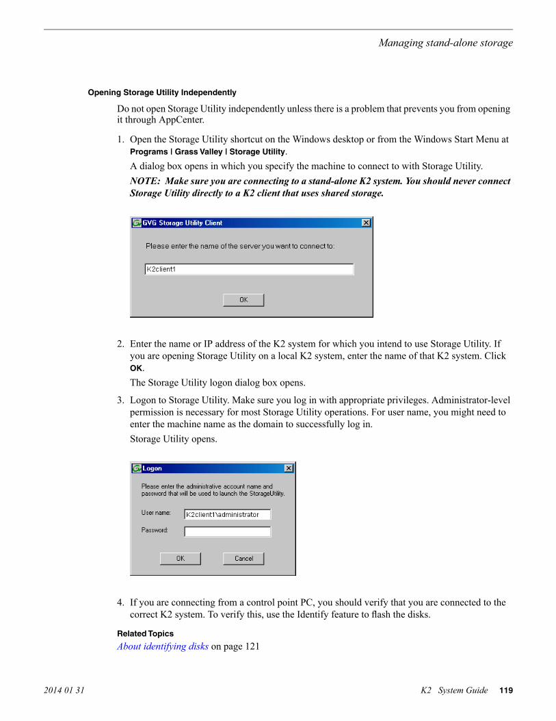
Opening Storage Utility Independently
Do not open Storage Utility independently unless there is a problem that prevents you from openingit through AppCenter.
1. Open the Storage Utility shortcut on the Windows desktop or from the Windows Start Menu atPrograms | Grass Valley | Storage Utility.A dialog box opens in which you specify the machine to connect to with Storage Utility.NOTE: Make sure you are connecting to a stand-alone K2 system. You should never connectStorage Utility directly to a K2 client that uses shared storage.
2. Enter the name or IP address of the K2 system for which you intend to use Storage Utility. Ifyou are opening Storage Utility on a local K2 system, enter the name of that K2 system. ClickOK.The Storage Utility logon dialog box opens.
3. Logon to Storage Utility. Make sure you log in with appropriate privileges. Administrator-levelpermission is necessary for most Storage Utility operations. For user name, you might need toenter the machine name as the domain to successfully log in.Storage Utility opens.
4. If you are connecting from a control point PC, you should verify that you are connected to thecorrect K2 system. To verify this, use the Identify feature to flash the disks.
Related Topics
About identifying disks on page 121
2014 01 31 K2 System Guide 119
Managing stand-alone storage

Overview of Storage Utility
Controllers inDevice
Controller
Bound LUNs
LUN
Unbound Disks
Disks
Status area(displays status ofthe selected item)
The Storage Utility user interface includes a tree view in the left-hand pane, and a status informationarea displayed in the right-hand pane. The tree view displays the hardware that makes up the storagesystem connected. The context menus in the tree view are used to configure storage. The right-handstatus pane displays information about the item selected in the tree view. The tree view hierarchyis as follows:
Controllers in Device — Provides a logical grouping of RAID Controllers by device.
Controller — Represents the RAID Controllers found. These are numbered in the order discovered.The controller icon represents both RAID Controller A and, if installed, RAID Controller B. Todetermine if an optional RAID Controller B is installed, select the Controller icon in the tree view,then examine the status pane for peer status.
Bound LUNs — Expanding the Bound node displays all bound LUNs.
LUN — Represents a bound LUN. Expanding the LUN node displays the disk modules that makeup the LUN.
UnBound disks — Expanding the UnBound node, displays all unbound disk modules.
Disks — Represents the disk modules.
The Storage Utility detects disks available and lists them on the opening screen.
Refer to the following procedures to use Storage Utility for maintenance tasks
120 K2 System Guide 2014 01 31
Managing stand-alone storage

Checking storage subsystem status
Some limited status information for storage subsystems is displayed in the Storage Utility. This canbe helpful when configuring storage.
You can view status information by selecting items in the tree view.
Status information displayedItem in tree view
Number of ControllersControllers in Device
Microcode VersionController
Number of LUNsBound
Binding Type, such as RAID 1 State (online or offline)LUN
Firmware
Vendor
State
Product ID
Capacity
Disk
Number of disksUnbound
Checking controller microcode
As explained in the previous section, to check controller microcode, select the controller in the treeview and the microcode version is displayed.
About identifying disks
The Identify feature allows you to flash the disk LEDs so that you can physically locate a specificdisk module or group of disk modules that make up a LUN. Always use the disk identify featurebefore removing and replacing a failed disk module. Accidentally removing the wrong disk modulecan destroy all data on the disk drives.
You can also use this feature to verify the K2 system to which you are currently connected.
Identifying internal disks
1. Open Storage Utility and in the tree view expand all nodes so that all disks are displayed.2. On the K2 Summit system, remove the front bezel assembly. On the K2 Solo Media Server, disk
LEDs are visible without removing the bezel.NOTE: Replace the bezel assembly within one minute to maintain system cooling.
2014 01 31 K2 System Guide 121
Managing stand-alone storage

3. The tables below illustrates the position of drives as numbered in the K2 Summit/Solo systemchassis. Compare the drive number positions and the disk numbering displayed in Storage Utilityto identify drive locations.K2 Summit 3G Production Client
Disk0
Disk1
Disk2
Disk3
Disk4
Disk5
Disk6
Disk7
Disk8
Disk9
Disk10
Disk11
First generation K2 Summit Production Client
Disk 2 Disk 4 Disk 7
Disk 1 Disk 3 Disk 6
Disk 0 Disk 5
K2 Solo Media Server
Disk 0
Disk 1
4. Position yourself so you can see the RAID drive LEDs.5. Identify the disks in a LUN or identify a single disk, as follows:
a) In the Storage Utility tree view, right-click a LUN or right-click a single disk, then selectIdentify LUN or Identify Disk in the context menu.A message box opens with a message that informs you that a disk or disks are blinking.
b) View disks.The LEDs display an amber color flashing several times a second. This flashing pattern canstop automatically after a specific time interval, such as ten seconds.
c) Verify the location of the disk or disks.
Get controller logs
1. In the tree view, select the controller.2. Click Actions | Get Controller Logs.3. A message informs you of the location of the logs.4. Find the following files on the local K2 Summit/Solo system at C:\logs:
tty.log
ControllerEvents.log
122 K2 System Guide 2014 01 31
Managing stand-alone storage

Check disk mode pages
1. In the tree view, right-click the controller and select Check DIsk Mode Pages.2. Messages report the results of the check. For each disk that has mode pages set incorrectly, click
Yes when prompted “…restore the default mode page settings?”.
Disabling a disk
1. In the tree view, right-click the disk and select Advanced | Disable and OK to confirm.A message “The drive is spinning down…Please wait” appears.If internal storage, the Service LED on the K2 system displays a flashing yellow pattern threetime a second.
2. When the message “Operation succeeded…now safe to remove disk” appears, click OK.3. The Storage Utility displays red Xs on tree view icons to represent a disk fault and a degraded
LUN.
NOTE: On the K2 Media Client, remember that the LUN 0 (disks 0_0 and 0_1) is the systemdrive. Do not attempt disk operations on the system drive.
Forcing a disk to rebuild
With RAID 0 there is no RAID redundancy, so disks do not rebuild. With other RAID types, suchas RAID 1, if media access (record/play) is underway, when you insert a media disk it automaticallybegins to rebuild. If there is no media access underway, to start the rebuild process either begin amedia operation or use the following procedure:
1. In the tree view, identify the faulty disk . If the disk is not currently in the fault state, theRebuild option is not available.
2. In the tree view, right-click the faulty disk and select Rebuild.3. When the message “Succeeded to start rebuild…” appears, click OK.
If internal storage, the Service LED on the K2 system displays a flashing pattern alternatingyellow/green once a second.
Unbind LUN
With internal storage, you can only unbind one LUN at a time. Also make sure the controller is notbusy with other processes, such as rebuilding a disk. If the controller is busy, the unbind LUNoperation fails.
CAUTION: Unbinding destroys all data stored on disk modules.
2014 01 31 K2 System Guide 123
Managing stand-alone storage

Refer to topics about direct-connect external storage before using this procedure on direct-connectsystems.
1. In the tree view, right-click the LUN and select Unbind LUN.2. If online, messages appear “…offline mode now?” and “…continue?”. Click Yes to put the
system in offline mode.AppCenter channels go offline.
3. When warning messages appear “…destroy all existing media…” and “Are you sure?”, clickOK to continue.
4. The Progress Report opens and displays unbind progress.
5. When progress reports 100% complete, the LUN is unbound.6. Restart the K2 system.
NOTE: On the K2 Media Client, remember that the LUN 0 (disks 0_0 and 0_1) is the systemdrive. Do not attempt disk operations on the system drive.Related Topics
About the direct-connect Fibre Channel card on page 175
Bind Luns
When you bind a LUN, you select one or more unbound disks and create a new LUN. The StorageUtility places this new LUN at the bottom of the list and numbers it accordingly. However, withinternal storage, disk numbers are enforced by the chassis slot in which the disk resides. Therefore,depending on the number and sequence of LUNs created, it is possible that the LUN numbers andthe disk numbers do not match. When you create a new file system, this mismatched numberingdoes not hamper functionality. However, to make the internal storage K2 system easy to service,you should retain the correct numbering sequence. To do this you must unbind all media LUNs andthen bind disks in sequence. On a K2 Media Client, do not unbind LUN0, which is the system drive.
Refer to topics about direct-connect external storage before using this procedure on direct-connectsystems.
1. In the tree view, right-click the Unbound node and select Bind LUN.
124 K2 System Guide 2014 01 31
Managing stand-alone storage

2. If online, messages appear “…offline mode now?” and “…continue?”. Click Yes to put thesystem in offline mode.
AppCenter channels go offline.
The Bind LUN dialog box opens showing all unbound disks for the controller listed in theAvailable Disk list.
3. Make a selection in the LUN Type drop-down list and proceed as follows:
• RAID 0 — For K2 Solo systems. Optional for internal storage first generation K2 Summitsystems and K2 Summit 3G systems.
In the Available Disks list, select one media disk, then click the arrow button to add it to theSelected Disks list. K2 Solo Media Server supports RAID 0 only.
• RAID 1 — For internal storage first generation K2 Summit systems and K2 Summit 3Gsystems.
In the Available Disks list, select two contiguous disks, then click the arrow button to addthem to the Selected Disks list. (TIP: Use ‘shift-click’ or ‘control-click’ to select disks.)
• RAID 5 — For direct-connect storage on K2 Summit systems.
In the Available Disks list, select six contiguous disks, then click the arrow button to addthem to the Selected Disks list. (TIP: Use ‘shift-click’ or ‘control-click’ to select disks.)
NOTE: As an aid in identifying a disk module’s physical location, select it in the SelectedDisks list, then click Identify Disks. This causes the disk drive LED to flash.
4. Click OK to close the Bind LUN dialog box and begin the binding process.The Progress Report opens and displays binding progress.
5. Repeat the previous steps for remaining unbound disks. You do not need to wait until the firstLUN is bound before you can start binding the next LUN. Multiple LUNs can be in the bindingprocess all at the same time.
2014 01 31 K2 System Guide 125
Managing stand-alone storage
6. When progress reports 100% complete for all the LUNs that you are binding, proceed to the nextstep.
7. Restart the K2 system.8. After binding one or more new LUNs, you must make a new file system.
Related Topics
About the direct-connect Fibre Channel card on page 175Making a new media file system on a K2 Summit/Solo on page 127
Changing RAID type for internal storage
On an internal storage K2 Summit 3G system, you can change the internal media storage to be eitherRAID 1 or RAID 0, as follows:
• RAID 1 — Recommended for the “full” media drive option, which is eight drives on a firstgeneration K2 Summit system. Not recommended for media drive options with fewer drives.With RAID 1, two media drives are configured as a mirrored pair to make one LUN. The capacityof each LUN is roughly equivalent to the capacity of one drive, so your total media storagecapacity is approximately 50% of the sum total of all the drives. Since drives are mirrored ineach LUN, your media is protected against drive failure. If a drive fails, the other drive in theLUN provides continued media access while you replace the failed drive.
• RAID 0 — Required on K2 Solo Media Server. With RAID 0 there is no mirroring, so your totalmedia storage capacity is roughly equivalent to that of all drives combined. However, your mediahas no RAID protection against drive failure. If one media drive fails, the entire group of drivesfails and you lose all your media.
Depending on your needs for capacity versus protection, you can change from one RAID type toanother, as explained in the following procedure.
NOTE: This procedure loses all media.
1. If you need to retain media, transfer it to another K2 system or otherwise back it up.2. Unbind all media LUNs.3. Restart.4. Bind media drives, as one of the following:
• RAID 0 — Bind each media drive as a RAID 0 LUN.• RAID 1 — Bind the ten drives as five RAID 1 LUNs.
5. Restart.6. Make a new file system.7. If you backed up your media, you can now transfer it back.
Related Topics
Unbind LUN on page 123Bind Luns on page 124Making a new media file system on a K2 Summit/Solo on page 127
126 K2 System Guide 2014 01 31
Managing stand-alone storage

Making a new media file system on a K2 Summit/Solo
If your SNFS file system name is currently “default”, when you make a new file system the namechanges to “gvfs_hostname”, where hostname is the name of the stand-alone K2 system. Also,Storage Utility creates unique disk labels, which is a requirement for compatibility with Dyno PA.
1. Click Tools | Make New File System.2. If online, messages appear “…offline mode now?” and “…continue?”. Click Yes to put the
system in offline mode.AppCenter channels go offline. The Configuration File window opens.
3. You can view media file system settings, but do not attempt to change them. Click Accept.A “Making new file system. Please wait” message box displays progress.
4. When a message “Succeeded to make the new file system. The server will be restarted now”appears, click OK to restart.
5. If you have Macintosh systems accessing the stand-alone K2 system, you should check that theSNFS file system volume is configured correctly on the Macintosh systems. Refer to K2 FCPConnect procedures in the K2 FCP Connect Installation Manual.
2014 01 31 K2 System Guide 127
Managing stand-alone storage

Checking the media file system
Prerequisites are as follows:
• Media operations must be stopped. You must put the standalone K2 System offline as part ofthis procedure.
This procedure checks the media file system but retains current media files.
1. In Storage Utility, click Tools | Check File System.2. If online, messages appear “…offline mode now?” and “…continue?”. Click Yes to put the
system in offline mode.AppCenter channels go offline.
3. A message box appears “Checking media file system. Please wait”. Observe progress.If problems are discovered they are reported. If the check process passes, when the process iscomplete a message appears to confirm success.
4. Click OK to dismiss the results.5. Messages appear “…online mode now?” and “…continue?”. Do one of the following:
• Click Yes to put the system in online mode. This is the recommended option in most cases.For example, even if you plan to next clean unreferenced files and/or movies, that operationrequires that the system be online, so you should put it online now. When you click Yes,AppCenter channels go online.
• Click No to keep the system in offline mode. This is not recommended for most cases. Onlydo this when you are sure that subsequent operations require the system to be offlline.
Your file system has been checked.
Cleaning unreferenced files and movies
Prerequisites are as follows:
• The standalone K2 system must be online. If K2 AppCenter channels are in the offline state, theclean unreferenced files/movies operations fail.
These procedures allow you to keep the media database and the media files in sync. You can checkthe movies (clips) in the media database for the references to media files that should be currently
128 K2 System Guide 2014 01 31
Managing stand-alone storage

stored on the media disks. Likewise, you can check for media files that are not referenced by a moviein the media database. If you find any unreferenced files or movies, you can delete them.
Clean unreferenced files
1. In Storage Utility, click Tools | Clean Unreferenced Files.2. A message box appears “…searching …Please wait”. Observe progress.3. A message box reports results. Respond as follows:
• If no unreferenced files are found, click OK to dismiss the results.• If unreferenced files are discovered, you are prompted to delete them. Click Yes to delete the
files or No to leave the files intact.
The process writes a log file to C:\profile\logFS.txt, which you can check for more information.
Clean unreferenced movies
1. In Storage Utility, click Tools | Clean Unreferenced Movies.2. A message box appears “…searching …Please wait”. Observe progress.3. A message box reports results. Respond as follows:
• If no unreferenced movies are found, click OK to dismiss the results.• If unreferenced movies are discovered, you are prompted to delete them. Click Yes to delete
the movies or No to leave the movies intact.
The process writes log files to C:\profile\cleanupDB.txt and C:\profile\MediaDB.txt, whichyou can check for more information.
Downloading controller microcode
You might be instructed in K2 release notes to upgrade controller microcode. This allows you totake advantage of enhancements and benefit from improved performance and reliability.
To determine your current controller microcode version, select the controller in the Storage Utilitytree view, then in the properties reported in the right-hand pane, note the controller microcodeversion. Use the following procedure if you need to download controller microcode.
1. Refer to K2 Release Notes to determine microcode types, versions, files, and any other specialinstructions regarding the particular controller microcode you are downloading.
2. In the Storage Utility, right-click the controller in the tree view, then select Load ControllerMicrocode in the context menu.
3. If online, messages appear “…offline mode now?” and “…continue?”. Click Yes to put thesystem in offline mode.AppCenter channels go offline. The Open File dialog box opens.
4. In the Open File dialog box, browse to the desired microcode file, select the file.5. Click OK.
The Progress Report window appears showing the microcode download task and the percentagecompletion.
6. When finished, exit Storage Utility.
2014 01 31 K2 System Guide 129
Managing stand-alone storage

7. Put AppCenter channels back online.8. Restart.
Downloading disk drive firmware
You might be instructed in K2 release notes to upgrade disk drive firmware. This allows you to takeadvantage of the disk drive enhancements and benefit from improved performance and reliability.
To determine your disk drive type and current firmware version, select a disk drive icon in theStorage Utility tree view, then note the drive properties reported in the right-hand pane. Use thefollowing procedure if you need to download disk drive firmware.
NOTE: The disk drives are upgraded one at a time which can take as long as 2 minutes per drive.Take this into consideration when scheduling the upgrade.
1. Refer to K2 Release Notes to determine firmware types, versions, files, and any other specialinstructions regarding the particular disk drive firmware you are downloading.
2. In the Storage Utility, right-click a disk in the tree view, then select Advanced | Download DiskFirmware in the context menu.
3. If online, messages appear “…offline mode now?” and “…continue?”. Click Yes to put thesystem in offline mode.AppCenter channels go offline. The Open File dialog box opens.
4. In the Open File dialog box, browse to the latest firmware file for your disks, select the file, andclick OK.
For internal drives, watch the lights on the drive to which you are downloading firmware. Thelights flash as firmware loads. Wait until the lights have completed their flashing pattern. Thiscan take several minutes.The Progress Report window appears showing the disk firmware download task and the percentagecompletion.
5. Repeat this procedure on each drive.6. When finished, exit Storage Utility.7. Put AppCenter channels back online.8. Restart.
Placing the K2 system into online mode
If the stand-alone K2 system is in offline mode and you have completed your storage systemconfiguration tasks, you have the following options to return the system to the online mode:
• Exit Storage Utility and bring channels online — If Storage Utility is closed, first open StorageUtility and then exit Storage Utility. When you exit Storage Utility you are prompted “…backto online mode?". Click Yes.
After exiting Storage Utility, if AppCenter is open the channels remain offline. To bring channelsonline, if you are running AppCenter on a Control Point PC, select System | Reconnect. If youare running AppCenter on a local K2 system, close and reopen AppCenter.
• Restart the K2 system — Restarting automatically resets the system to online mode. When youlog into AppCenter channels connect and come up online.
130 K2 System Guide 2014 01 31
Managing stand-alone storage

Managing stand-alone K2 systems withSiteConfig
About managing stand-alone K2 clients with SiteConfig
The topics in this section apply to the following K2 client products:
• K2 Summit Production Client with internal storage• K2 Summit Production Client with direct-connect storage
Work through the topics sequentially to get SiteConfig set up to remotely configure and manageone or more K2 clients. Then you can use SiteConfig for software upgrades and other managementtasks.
SiteConfig and stand-alone K2 clients checklist
Use the following sequence of tasks as a guideline to set up SiteConfig and do your initialconfiguration for one or more stand-alone K2 clients. This checklist outlines the recommendedworkflow for a new system.
CommentTask
Review system requirements and networkaccess requirements about installingSiteConfig.
Select a PC to use as the SiteConfig controlpoint PC
—Install SiteConfig on the control point PC
If you already have a SiteConfig systemdescription managing other devices in yourfacility, you can use that system descriptionalso for your stand-alone K2 clients, ratherthan creating a new system description.
Create a system description and add a customsite to the system description
—Add a control network to the site. You canalso add a FTP/streaming network if desired
—Add a group for your K2 clients to the systemdescription
—Add a placeholder K2 client to the systemdescription for each of your actual K2 clients
—Configure the names of the placeholder K2clients
Specify IP address ranges and other networkdetails
Configure the network interfaces of theplaceholder K2 clients
2014 01 31 K2 System Guide 131

CommentTask
—Discover your K2 clients
—Assign each discovered K2 client to itsplaceholder K2 client
On each K2 client, set the control networkinterface IP address first, then theFTP/streaming network interface, if present.Also set the hostname.
For each discovered and assigned K2 client,edit each network interface. Specify networksettings and apply them to the K2 client.
—Add a control point PC placeholder device tothe system description
—Discover the control point PC and assign itto the placeholder control point PC
Make sure the device name is correct, thenmake the hostname the same as the devicename.
If not already set correctly, set the hostnameof discovered devices
—Ping each K2 client and the control point PCto test network communication
Make sure you have completed networkconfiguration of all network interfaces acrossall devices to ensure complete and valid hosttable information. You can use SiteConfig tocopy hosts files to devices, or you canmanage hosts files yourself.
Generate host table information and distributeto hosts files on each K2 client and on thecontrol point PC
—Create a deployment group
—Add stand-alone K2 clients to the deploymentgroup
System requirements for SiteConfig host PC
The PC on which SiteConfig is installed must meet the following requirements:
CommentsRequirements
Microsoft Windows (Must be a U.S. version):
• XP Professional Service Pack 3• Server 2003• Vista Enterprise Service Pack 1• Windows 7• Server 2008 R2
Operating system
Minimum 512 MB, 1 GB recommendedRAM
Must have at least 128 MB memoryGraphics acceleration
Pentium 4 or higher class, 2 GHz or greaterProcessor
132 K2 System Guide 2014 01 31
Managing stand-alone K2 systems with SiteConfig

CommentsRequirements
400 MBHard disk space
Version 4.0Microsoft .NET Framework
1.3.1_12 and 1.4.2_05 or higher. Required forthe HP Ethernet Switch configuration interface,which is used for K2 SANs.
Java JRE
Microsoft XML 4 Service Pack 2 is required.XML
About installing SiteConfig
SiteConfig uses a protocol that involves sending Ethernet broadcast messages to discover andconfigure devices. To enable this protocol to work correctly, there must be unrestricted networkaccess between the PC that hosts SiteConfig and the devices to be discovered.
This is achieved if control network interfaces are all connected to the same switch or to multipleswitches interconnected with ISLs/trunks. If your site requires that other switches and/or routers bein the network path, you must make sure that no restrictions are in place that block SiteConfigprotocols.
Also, do not install SiteConfig on a PC on which a drive from a managed device is mapped as anadministrative share (C$). For example, if you have a PC set up to run anti-virus software and forthis purpose you have network drives set up on the PC mapped to C$ shares on devices, then do notuse that PC to host SiteConfig and manage those devices.
For a given system, there should be just one instance of SiteConfig managing the system.
Installing/upgrading SiteConfigPrerequisites:
• The PC on which you are installing SiteConfg meets system requirements.• The PC is connected to the LAN on which all the devices to be managed are connected.• There are no routed paths to the devices to be managed.
1. Procure SiteConfig installation files from the Grass Valley website or via other distributionmechanisms.The following directory and files are required to install SiteConfig:
• DotNetFx directory• ProductFrameUISetup.msi
• setup.exe
2. If you already have a version of SiteConfig installed, go to Windows Add/Remove Programs anduninstall it.
3. Double-click setup.exe.The installation wizard opens.
2014 01 31 K2 System Guide 133
Managing stand-alone K2 systems with SiteConfig

4. Work through the wizard pages, clicking Next and Finish.
If the PC does not have the appropriate version of Microsoft .NET, the SiteConfig installationprograms installs it.
5. Open the Windows operating system Services control panel on the PC and look for an entrycalled " ProductFrame Discovery Agent".The Discovery Agent must be installed on the SiteConfig PC so that the PC can be discoveredby SiteConfig and added to the system description as a managed device. This is necessary toensure name resolution in SiteConfig's hosts file.The Discovery Agent is also known as the Network Configuration Connect Kit. For example,in Windows Add/Remove Programs, it can be displayed as either Network Configuration ConnectKit or SiteConfig Discovery Agent.
6. Proceed as follows:
• If the Discovery Agent is not installed, navigate to the SiteConfig install location's DiscoveryAgent Setup subdirectory and double-click the DiscoveryAgentServiceSetup.msi file. Thislaunches the setup program and installs the Discovery Agent. Follow the setup wizard tocomplete installation. A restart is required after installation. Then continue with the next stepin this procedure.
• If the Discovery Agent is already installed, continue with the next step in this procedure.
7. If not already configured, configure the SiteConfig PC with a valid Ethernet IP address for theLAN using Windows Network Connections.
8. If you are not going to be using SiteConfig to manage system hosts files, put the system hostsfile on the SiteConfig PC.
134 K2 System Guide 2014 01 31
Managing stand-alone K2 systems with SiteConfig

Creating a system description for stand-alone K2 clientsDo not do this task if:
• You already have or are developing a SiteConfig system description managing other devices inyour facility and that system description has the correct networks and connectivity for yourstand-alone K2 clients. In this case, skip ahead to the task in which you add a group to the systemdescription for your stand-alone K2 clients.
Do this task if:
• You do not yet have a system description appropriate for managing your stand-alone K2 clients.
1. Open SiteConfig and proceed as follows:
• If a dialog box opens that gives you the choice of creating or importing a system description,it means SiteConfig does not have access to a system description file. Click Create.
• If the SiteConfig main window opens, click File | New.
The Create New System Description dialog box opens.
2. In the Create New System Description dialog box, enter the name of the file for the systemdescription you are creating.It is recommended that you store the system description file in the default location, rather thanbrowsing to store the file in a different location. SiteConfig always accesses the default location.
3. Click OK.A blank system description loads, which displays just the top-level System node in the tree view.
2014 01 31 K2 System Guide 135
Managing stand-alone K2 systems with SiteConfig

4. In the Network Configuration | Devices tree view, right-click the System node or a Site node andselect Add Site.
The New Site Wizard opens.
5. Enter a name for the site you are creating, considering the following:
• Keep the site name short, as it becomes the root identifier that is the default prefix for deviceand network names.
• Sites in the tree view are automatically sorted alphabetically.
6. Select Custom and click Next.7. Click Finish to create the site.
The site is displayed in SiteConfig in the tree view with groups and device placeholders displayedunder the site node. New networks are displayed in the tree view of networks in the Networks tab.
Creating the control network for stand-alone K2 clients
1. In the Network Configuration | Networks tree view, select a System node or a Site node.
136 K2 System Guide 2014 01 31
Managing stand-alone K2 systems with SiteConfig

2. Proceed as follows:
• To add a network under the currently selected node, in the tree view right-click the node andselect Add Network.
The Network Settings dialog box opens.
2014 01 31 K2 System Guide 137
Managing stand-alone K2 systems with SiteConfig
3. Configure the settings for the network as follows:
For control networkSetting...
Ethernet is requiredType
Control is requiredUsage
None is required. This is true even on a redundant K2 SAN. (Only theiSCSI network is redundant on a redundant K2 SAN.)
Redundancy
Control is recommendedName
Unselected is requiredExclude from HostFiles
Selected is requiredManaged
The first (lowest) IP address in the range of IP addresses managed bySiteConfig. Required.
Base IP Address
The number of IP addresses in the range managed by SiteConfig.Required.
Number of Addresses
The network's subnet mask. Required.Subnet Mask
Additional network settings managed by SiteConfig. Allowed.Gateway IP Address
Unselected is required. Related settings are disabled.Unmanaged
Servers providing DNS for name resolution. Allowed.DNS Servers
Not allowedDefault InterfaceName Suffix
4. Click OK to save settings and close.
Creating the FTP/streaming network for stand-alone K2 clients (optional)If you transfer media to/from the stand-alone K2 client, create a FTP/streaming network.
1. In the Network Configuration | Networks tree view, select a System node or a Site node.2. Proceed as follows:
• To add a network under the currently selected node, in the tree view right-click the node andselect Add Network.
The Network Settings dialog box opens.
138 K2 System Guide 2014 01 31
Managing stand-alone K2 systems with SiteConfig

3. Configure the settings for the network as follows:
For FTP/streaming networkSetting...
Ethernet is requiredType
FileTransfer is requiredUsage
None is required. This is true even on a redundant K2 SAN. (Only theiSCSI network is redundant on a redundant K2 SAN.)
Redundancy
Streaming is recommendedName
Unselected is requiredExclude from HostFiles
Selected is requiredManaged
The first (lowest) IP address in the range of IP addresses managed bySiteConfig. Required.
Base IP Address
The number of IP addresses in the range managed by SiteConfig.Required.
Number of Addresses
The network's subnet mask. Required.Subnet Mask
Additional network settings managed by SiteConfig. Allowed.Gateway IP Address
Unselected is required. Related settings are disabled.Unmanaged
Servers providing DNS for name resolution. Allowed.DNS Servers
_he0 is requiredDefault InterfaceName Suffix
4. Click OK to save settings and close.
Adding a group
1. In the Network Configuration | Networks tree view, right-click a site node and select Add Group.The group appears in the tree view.
2. Right-click the group and select Rename.3. Enter the desired name for the group.
2014 01 31 K2 System Guide 139
Managing stand-alone K2 systems with SiteConfig

Adding stand-alone K2 clients to the system descriptionPrerequisites for this task are as follows:
• The system description contains a group.
1. In the Network Configuration | Devices tree view, right-click a group and select Add Device.
2. Configure settings for the device you are adding as follows:
• Family – Select K2.• Type – Select the appropriate type of K2 system.• Model – Select the model with the appropriate storage.• Name – This is the device name, as displayed in the SiteConfig device tree view and device
list view. This name can be different than the host name (network name). You can accept thedefault name or enter a name of your choice. Devices in the tree view are sorted alphabetically.
• Amount – You can add multiple devices, as currently defined by your settings in the AddDevice dialog box. An enumerator is added to the name to create a unique name for eachdevice added.
• Control network– Select the control network.• Starting Address – Select from the list of available addresses on the selected control network.
If adding multiple devices, this is the starting address, with addresses assigned sequentiallyto each device added.
3. Click OK to save settings and close.4. Repeat these steps for each of your stand-alone K2 clients.
Modifying stand-alone K2 client unassigned (unmanaged) interfacesPrerequisites for this task are as follows:
• The system description has a stand-alone K2 client that is a placeholder device.
140 K2 System Guide 2014 01 31
Managing stand-alone K2 systems with SiteConfig

• The placeholder device has a one or more unmanaged network interfaces.
Use this task to modify unmanaged network interfaces on a standalone K2 client as follows:
• K2 Summit Production Client©
1. In the Network Configuration | Devices tree view, select a stand-alone K2 client placeholder device.
The interfaces for that device are displayed in the interfaces list view.
Edit the control network interface first.
2. In the interfaces list view, right-click an interface and select Edit.
The Unmanaged Network Interface Details dialog box opens.
2014 01 31 K2 System Guide 141
Managing stand-alone K2 systems with SiteConfig

3. Configure the settings for the interface as follows:
For control network interfaceSetting...
Control is requiredNetwork
The IP address for this interface on the network. Required.IP Address
The device host name. Required.Interface Name
Not recommended. Sets the interface name to SiteConfig default convention,based on the root Site name and device-type.
Set to Default
Unselected is required. Since not selected, the default behavior occurs, whichis to use the device host name in the hosts file.
...use InterfaceName/Aliases inHost Files...
Not allowedAliases
Allowed, if applicable to the network. The DNS suffix is added to theinterface name.
DNS Suffix
4. Click OK to save settings and close.5. If you have a FTP/streaming network, repeat these steps but select the stand-alone K2 client's
other network interface and configure settings as follows.
For FTP/streaming network interfaceSetting...
Streaming is requiredNetwork
The IP address for this interface on the network. Required.IP Address
The device host name with the " _he0" suffix added is required. For example,if the host name is K2prod01, then K2prod01_he0 is required here.
Interface Name
Not recommended. Sets the interface name to SiteConfig default convention,based on the root Site name and device-type.
Set to Default
Selected is required...use InterfaceName/Aliases inHost Files...
Not allowedAliases
Allowed, if applicable to the network. The DNS suffix is added to theinterface name.
DNS Suffix
6. Click OK to save settings and close.7. Repeat this procedure for each of your stand-alone K2 client placeholder devices.
Discovering devices with SiteConfigPrerequisites for this task are as follows:
• The Ethernet switch or switches that support the control network are configured and operational.If multiple switches, ISLs are connected and trunks configured.
142 K2 System Guide 2014 01 31
Managing stand-alone K2 systems with SiteConfig
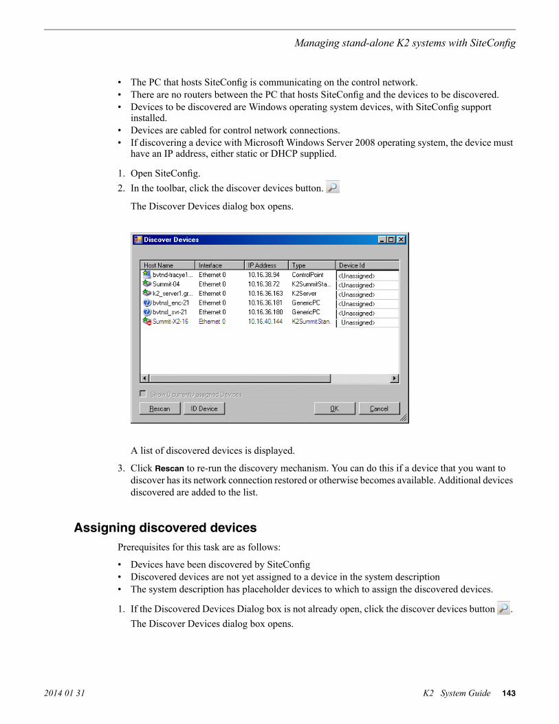
• The PC that hosts SiteConfig is communicating on the control network.• There are no routers between the PC that hosts SiteConfig and the devices to be discovered.• Devices to be discovered are Windows operating system devices, with SiteConfig support
installed.• Devices are cabled for control network connections.• If discovering a device with Microsoft Windows Server 2008 operating system, the device must
have an IP address, either static or DHCP supplied.
1. Open SiteConfig.2. In the toolbar, click the discover devices button.
The Discover Devices dialog box opens.
A list of discovered devices is displayed.
3. Click Rescan to re-run the discovery mechanism. You can do this if a device that you want todiscover has its network connection restored or otherwise becomes available. Additional devicesdiscovered are added to the list.
Assigning discovered devicesPrerequisites for this task are as follows:
• Devices have been discovered by SiteConfig• Discovered devices are not yet assigned to a device in the system description• The system description has placeholder devices to which to assign the discovered devices.
1. If the Discovered Devices Dialog box is not already open, click the discover devices button .The Discover Devices dialog box opens.
2014 01 31 K2 System Guide 143
Managing stand-alone K2 systems with SiteConfig

2. Identify discovered devices.
• If a single device is discovered in multiple rows, it means the device has multiple networkinterfaces. Choose the interface that represents the device's currently connected controlconnection. This is typically Ethernet ... 0.
• If necessary, select a device in the list and click ID Device. This triggers an action on thedevice, such as flashing an LED or ejecting a CD drive, to identify the device.
3. To also view previously discovered devices that have already been assigned to a device in thesystem description, select Show … currently assigned devices.The currently assigned devices are added to the list. Viewing both assigned and unassigneddevices in this way can be helpful to verify the match between discovered devices and placeholderdevices.
4. In the row for each discovered device, view items on the Device Id drop-down list to determinethe match with placeholder devices, as follows:
• If SiteConfig finds a match between the device-type discovered and the device-type of oneor more placeholder devices, it displays those placeholder devices in the list.
• If SiteConfig does not find a match between the device-type discovered and the device-typeof a placeholder device, no placeholder device is displayed in the list.
5. In the row for a discovered device, click the Device Id drop-down list and select the placeholderdevice that corresponds to the discovered device.If there is no corresponding placeholder device currently in the system description, you can selectAdd to create a new placeholder device and then assign the discovered device to it.
6. When discovered devices have been assigned, click OK to save settings and close.7. In the Network Configuration | Devices tree view, select each of the devices to which you assigned
a discovered device.
Modifying stand-alone K2 client managed network interfacesPrerequisites for this task are as follows:
• The physical device you are configuring has been discovered and is assigned to a device in theSiteConfig system description.
• SiteConfig has communication with the device.• The device is defined in the system description with an appropriate network interface.
Use this task to modify managed network interfaces on stand-alone K2 client models as follows:
• K2 Summit Production Client
1. In the tree view select a K2 client, then in the Interfaces list view, identify interfaces as follows:
• For a stand-alone K2 Summit Production Client, the control network interface is a team.Modify the control team interface first. The control team is comprised of two individualinterfaces, one for Control Connection #1 and one for Control Connection # 2. If theseindividual interfaces are displayed, do not modify them.
• A stand-alone K2 client's other interface is for FTP/streaming. If you have a FTP/streamingnetwork, you can configure and use this interface if desired.
144 K2 System Guide 2014 01 31
Managing stand-alone K2 systems with SiteConfig

2. In the Interfaces list view determine the interface to configure, as follows:
• Identify the interface with which SiteConfig is currently communicating, indicated by thegreen star overlay icon. This should be the control network interface.
• Verify that the interface over which SiteConfig is currently communicating is in fact theinterface defined for the control network in the system description. If this is not the case, youmight have the control network cable connected to the wrong interface port. The controlconnection should always be the first port on the motherboard, except when you have aloopback connection.
• Configure the control network interface first before configuring any of the other interfaces.• After you have successfully configured the control network interface, return to this step to
configure each remaining interface.
3. In the Interfaces list view, check the icon for the interface you are configuring.
If the icon has a red stop sign overlay, it indicates that current settings and planned settings donot match or that there is some other problem. Hover over the icon to read a tooltip withinformation about the problem.NOTE: Make sure that the device is unlocked in SiteConfig before proceeding. For a K2Summit Production Client with K2 software at a version lower than 9.0, this disables the writefilter.
2014 01 31 K2 System Guide 145
Managing stand-alone K2 systems with SiteConfig

4. In the Interfaces list view, right-click the interface you are configuring and select Edit.
The Managed Network Interface Details dialog box opens.
5. Identify the interface on the discovered device that you are configuring.
• Identify Ethernet LAN adapters by their "Description" name. This is the Windows connectionname. SiteConfig reads this name from the device and displays it at the top of this dialog box.This is the most accurate way to identify the network adapter on the discovered device thatyou are configuring.
• For a K2 Summit Production Client, when you configure its first interface, make sure youare configuring the 'Control Team' interface.
146 K2 System Guide 2014 01 31
Managing stand-alone K2 systems with SiteConfig

6. Configure naming settings as follows:
For network interface Control TeamSetting...
The device host name. Required.Interface Name
Not recommendedSet To Default
Allowed, if applicable to the network. The DNS suffix is added to theinterface name.
DNS Suffix
Not allowedAliases
Unselected is required. Since not selected, the default behavior occurs, whichis to use the device host name in the hosts file.
Use InterfaceName/Aliases inHost Files
7. Evaluate settings on the Planned tab and change if necessary.
• Compare settings on the Planned tab with settings on the Current tab.• If you want to keep the current settings as reported in the Current tab, click Remove to remove
the planned settings.• Do not specify multiple IP addresses for the same interface. Do not use the Add button.• Refer to SiteConfig Help Topics for information about planned and current IP configuration.
2014 01 31 K2 System Guide 147
Managing stand-alone K2 systems with SiteConfig

8. To modify planned settings, do the following:a) Select the network settings and click Edit.
The Edit IP Address dialog box opens.
b) Edit IP address settings as follows:
For network interface Control TeamSetting...
Control is requiredNetwork
Static is recommended.Address Allocation
The IP address for this interface on the network. Required.IP Address
The networks listed in the Edit IP Address dialog box are those currently defined in the systemdescription, with available settings restricted according to the network definition. If yourequire settings that are not available, you can close dialog boxes and go to the NetworkConfiguration | Networks tab to modify network settings, then return to the Edit IP Addressdialog box to continue.
9. When you have verified that the planned settings are correct, click OK, then Yes to apply settingsto the device and close.A Contacting Device message box reports progress.
148 K2 System Guide 2014 01 31
Managing stand-alone K2 systems with SiteConfig

10. After configuring control network settings, do the followinga) If a message informs you of a possible loss of communication, click OK.
This message is normal, since this is the network over which you are currently communicating.b) In the Device list view, observe the device icon and wait until the icon displays the green star
overlay before proceeding.
The icon might not display the green star overlay for several seconds as settings arereconfigured and communication is re-established.
c) In the Interface list view, right-click the interface and select Ping.
The Ping Host dialog box opens.
If ping status reports success, the interface is communicating on the control network.
11. If you have a FTP/streaming network, repeat steps but select the stand-alone K2 client's othernetwork interface. Open the Managed Network Interface Details dialog box and configure theinterface for the FTP/streaming network.
12. Identify the interface on the discovered device that you are configuring.
• On any stand-alone K2 client, for the FTP/streaming network, configure Media Connection#1.
13. Configure naming settings as follows:
For network interface Media Connection #1Setting...
The device host name with the "_he0" suffix added is required.Interface Name
Not recommendedSet To Default
Allowed, if applicable to the network. The DNS suffix is added to theinterface name.
DNS Suffix
Not allowedAliases
Selected is requiredUse InterfaceName/Aliases inHost Files
14. As in steps earlier in this procedure, reconcile planned and current settings. If you must edit theIP address, make settings as follows:
For network interface Media Connection#1Setting...
Streaming is requiredNetwork
Static is required.Address Allocation
The IP address for this interface on the network. Required.IP Address
2014 01 31 K2 System Guide 149
Managing stand-alone K2 systems with SiteConfig

15. When you have verified that the planned settings are correct, click OK, then Yes to apply settingsto the device and close.A Contacting Device message box reports progress.NOTE: For a K2 Summit Production Client with K2 software at a version lower than 9.0,when configuration is complete, make sure you lock the device in SiteConfig. This enablesthe write filter.
Adding a control point PC placeholder device to the system descriptionPrerequisites for this task are as follows:
• The system description contains a group.
1. In the Network Configuration | Devices tree view, right-click a group and select Add Device.
The Add Device dialog box opens.
2. Configure settings for the device you are adding as follows:
• Family – Select System Management.• Type – Select ControlPoint PC.• Model – Select Control Point PC.• Name - This is the device name, as displayed in the SiteConfig device tree view and device
list view. You must configure this name to be the same as the host name on the actual controlpoint PC.
• Amount – Leave this setting at 1. Do not attempt to configure multiple control point PCsimultaneously.
• Control Network – Select the control network.• Starting Address – Select the IP address that is the address currently configured on the actual
control point PC.
3. Click OK to save settings and close.
150 K2 System Guide 2014 01 31
Managing stand-alone K2 systems with SiteConfig

Verify that IP settings for the placeholder device's control network interface are identical to thoseon the actual control point PC before using SiteConfig to discover the control point PC on the controlnetwork.
Assigning the control point PCPrerequisites for this task are as follows:
• The SiteConfig control point PC has the SiteConfig Discovery Agent installed. The DiscoveryAgent is also known as the Network Configuration Connect Kit. In Windows Add/RemovePrograms, it can be displayed as either Network Configuration Connect Kit or SiteConfigDiscovery Agent.
• The system description contains a control point PC placeholder device.• The placeholder's control network interface is configured with the control network IP address
that is currently on the actual control point PC.• The device name of the control point PC placeholder is same as the host name of the actual
control point PC.
In this procedure you discover the physical control point PC and assign it to the placeholder controlpoint PC in the system description.
1. Open SiteConfig on the control point PC.2. Discover devices and identify the control point PC discovered device.3. Assign the discovered device to the control point PC placeholder.4. In the Network Configuration | Devices tree view, select the control point PC.5. In the Interfaces list view, right-click the control network interface and select Edit.
The Managed Network Interface Details dialog box opens.
6. Evaluate IP settings as follows:
• If only Current settings are displayed (the Planned tab is not displayed), it means the plannedsettings you configured on the placeholder device are identical to those on the actual controlpoint PC If this is the case, no further configuration is required.
• If both a Current tab and a Planned tab are displayed, it means the planned settings youconfigured on the placeholder device are not identical to those on the actual control point PC.If this is the case, do not apply planned settings. Doing so overwrites IP settings on the actualcontrol point PC, which stops network communication. Instead, select the Planned tab andclick Remove.
NOTE: Do not click OK if planned settings (red text) are displayed.
7. When you are sure that only Current settings are displayed and that those are the current validsettings for the control point PC, click Apply, then OK to save settings and close.
Making the host name the same as the device name
1. Verify that the current device name, as displayed in the SiteConfig tree view, is the same as yourdesired host name.
2. In the Network Configuration | Devices | Device list view, right-click the device and select Edit.The Edit Device dialog box opens.
2014 01 31 K2 System Guide 151
Managing stand-alone K2 systems with SiteConfig

3. Identify the state of buttons as follows:
• If the host name is different than the device name, the Set to Device Name button is enabled.• If the host name is the same as the device name, the Set to Device Name button is disabled.
4. If enabled, click Set to Device Name.This changes the host name to be the same as the device name.
5. Click OK.6. When prompted, restart the device.
Pinging devices from the PC that hosts SiteConfigPrerequisites:
• The devices you are pinging are in the SiteConfig system description.
You can send the ping command to one or more devices in the system description over the networkto which the SiteConfig host PC is connected. Typically this is the control network.
1. In the Network Configuration | Networks tree view, select a network, site, or system node.2. In the Devices list view, select one or more devices. Use Ctrl + Click or Shift + Click to select
multiple devices.3. Right-click the selected device or devices and select Ping.
The Ping Devices dialog box opens and lists the selected device or devices.
The Ping Devices dialog box reports the progress and results of the ping command per device.
About hosts files and SiteConfig
SiteConfig uses the network information in the system description to define a hosts file and allowsyou to view the hosts file. SiteConfig can manage this hosts file on Windows operating systemdevices that are in the system description and that are part of a SiteConfig managed network.
When you have successfully assigned devices and applied planned network settings to interfaces,it is an indication that host table information, as currently captured in the system description, is validand that you are ready to have SiteConfig assemble the host table information into a hosts file. Youroptions for placing this host table information on devices are as follows:
• If you do not want SiteConfig to manage your host table information, you can manage it yourself.This is typically the case if your facility has an existing hosts file that contains host tableinformation for devices that are not in the SiteConfig system description. In this case, you canhave SiteConfig generate a single hosts file that contains the host table information for the devicesin the system description. You can then copy the desired host table information out of theSiteConfig hosts file and copy it into your facility hosts file. You must then distribute your facilityhosts file to devices using your own mechanisms.
• If you want SiteConfig to manage all information in hosts files on devices, you can haveSiteConfig copy its hosts file to devices. In so doing, SiteConfig overwrites the existing hostsfiles on devices. Therefore, this requires that all devices that have name resolution through thehosts file be configured accordingly in the SiteConfig system description.
152 K2 System Guide 2014 01 31
Managing stand-alone K2 systems with SiteConfig

If you choose to have SiteConfig write hosts files to devices, the process consumes system resourceand network bandwidth. Therefore you should wait until you have verified the information for alldevices/interfaces in the host file, rather than updating hosts files incrementally as you discover/assigndevices.
SiteConfig does not automatically deploy hosts files to managed devices as you add or removedevices. If you add or remove devices from the system description, you must re-deploy the modifiedhosts file to all devices.
Generating host tables using SiteConfigPrerequisites for this task are as follows:
• Planned control network settings are applied to control network interfaces and devices arecommunicating on the control network as defined in the system description.
• Interfaces for networks that require name resolution via the hosts file, such as the FTP/streamingnetwork, have settings applied and are communicating.
• You have viewed host names, as currently defined in the system description, and determinedthat they are correct.
• The SiteConfig PC is added to the system description so that it is included in the host tablesgenerated by SiteConfig.
When you add or modify devices or their IP addresses in the SiteConfig system description, youshould update host tables on all devices that use them.
1. In the Network Configuration | Networks tree view, select a network, site, or system node.2. Click View Hosts file.
A Hosts File Contents window opens that displays the contents of the hosts file as currentlydefined in the system description.
3. Verify the information in the hosts file.
2014 01 31 K2 System Guide 153
Managing stand-alone K2 systems with SiteConfig

4. Do one of the following:
• If you are managing host table information yourself, click Save As and save a copy of thehosts file to a location on the control point PC. Then open the copy of the hosts file, copy thedesired host table information from it, and paste it into your facility hosts file as desired. Thenyou can use your own process to distribute the facility hosts file to devices. Remember todistribute to the control point PC so that SiteConfig and other management applications suchas K2Config can resolve network host names.
• If SiteConfig is managing hosts files, do the following:
NOTE: Writing hosts files to multiple devices consumes system resource and networkbandwidth. Therefore it is recommended that you wait and do this after the system is completeand fully implemented, rather than updating hosts files incrementally as you discover/assigndevices.a) In the Network Configuration | Devices | Devices list view, right-click a device to which you
intend to write the hosts file and select View Current Host File.A Host File Contents window opens that displays the contents of the hosts file that is currentlyon that actual device.
b) Verify that there is no information that you want to retain in the device’s current hosts filethat is not also in the hosts file as currently defined in the system description. If you need tosave the device's current hosts file, click Save As and save to a different location.
c) In the Network Configuration | Devices | Devices list view, right-click a device or use Ctrl +Click to select multiple devices, and select Update Host File.The current hosts file is overwritten with the hosts file as defined in the system description.
Configuring deployment groupsPrerequisites for this procedure are as follows:
• The device is assigned in the SiteConfig system description and network connectivity is present.
1. In the Software Deployment | Deployment Groups tree view, right-click the top node and selectAdd Deployment Group.A deployment group appears in the tree view.
2. Right-click the deployment group, select Rename, and enter a name for the deployment group.
154 K2 System Guide 2014 01 31
Managing stand-alone K2 systems with SiteConfig

3. Right-click the deployment group and select Add Target Device.The Add Target Device(s) wizard opens.
4. In the Available Target Devices tree view, select the node that displays the devices that you arecombining as a deployment group.
5. In the right-hand pane, select the devices that you are combining as a deployment group.To select multiple devices, you can drag through the devices, use Ctrl + Click, or use Shift +Click.
6. Click OK.
The devices appear in the Deployment Groups tree view under the deployment group. Before youperform a software deployment, you must check software on the devices that will be receiving newsoftware. If you have already added packages to the group, on the Deployment Groups tab you willalso see deployment tasks generated for every device with roles that match the package contents.
About deploying software for stand-alone K2 clients
You must control the sequence of software deployment tasks and device restarts as you upgradesoftware. The exact steps can vary from software version to version. Make sure you follow thedocumented task flow in the release notes for the version of software to which you are upgrading.
2014 01 31 K2 System Guide 155
Managing stand-alone K2 systems with SiteConfig

156 K2 System Guide 2014 01 31
Managing stand-alone K2 systems with SiteConfig

Managing K2 system software
About K2 system software
Check K2 Release Notes for the latest information about software.
K2 system software components are as follows:
• K2 Client: Installed on K2 Summit/Solo system. Provides core functionality for all K2Summit/Solo system models.
• K2 Server: Installed on K2 Media Servers. Provides core functionality for all K2 Media Serversin all roles.
• Control Point: Installed on Control Point PCs. Provides remote control and configuration of K2Summit/Solo systems (both internal and external storage) as well as the K2 SAN.
• Media File System (SNFS): Installed on K2 Media Servers, stand-alone K2 Summit/Solo systems,and shared storage (SAN) K2 Summit/Solo system. Provides a dedicated file system for accessto media data. Install only as instructed by release notes.
In addition, the following software is installed in special cases:
• Multi-Path I/O software — You must install this software on K2 Summit systems that are partof a redundant K2 SAN and on K2 Summit systems with direct-connect storage.
On a K2 SAN system, Grass Valley requires that you use SiteConfig to install K2 system software.On a standalone K2 Summit/Solo system Grass Valley recommends SiteConfig but allows manualinstallation as well. You can access software on your K2 Summit/Solo system's USB RecoveryFlash Drive and via download from the Grass Valley website. On the USB Recovery Flash Drive,find SiteConfig *.cab files in the ProductFrame directory and find manual installation files in therelease directory.
Software components installed
Each of the K2 installation packages installs software components that provide the functionality forvarious applications and system tools. The components installed are as follows:
CommentsComponents installedSoftware
Provides the primary media functionality.Core system softwareK2 Client
Allows you to operate AppCenter on the local machine.AppCenter userinterface
Provides AppCenter functionality. It is accessed by both theremote AppCenter (on a Control Point PC) and the localAppCenter user interface.
AppServer
Configures the media storage on internal storage K2 clientsonly. Do not run Storage Utility on shared storage K2 clients.
Storage Utility
2014 01 31 K2 System Guide 157

CommentsComponents installedSoftware
Installed only on shared storage models. Provides to theremotely connected K2 System Configuration applicationthe ability to configure the local machine. You cannot runthe K2 System Configuration user interface on the local K2client.
K2 SystemConfiguration
Installation files copied to K2 client but software notinstalled.
Multi-Path I/O
Provides the primary media functionality.Core system softwareK2 Server
Provides functionality for the remotely connected StorageUtility that runs on the Control Point PC. You should notrun Storage Utility locally on the K2 Media Server.
Storage Utility
Provides to the remotely connected K2 SystemConfiguration application the ability to configure the localmachine. You cannot run the K2 System Configuration userinterface on the local K2 Media Server.
K2 SystemConfiguration
Connects to K2 clients for control and configuration ofchannels.
AppCenter userinterface
ControlPoint
Connects to K2 clients, K2 Media Servers, RAID storage,and Gigabit switches for configuration of the K2 SAN.
K2 SystemConfiguration userinterface
Connects to the K2 Media Server, and through the K2 MediaServer to the RAID storage, for configuration of the mediafile system, media database, and RAID storage.
Storage Utility
Installing Control Point softwareIf you are using the Grass Valley Control Point PC, it comes from the factory with software installed,so you should not need to install software.
If you intend to use a PC that you own as a Control Point PC, make sure that you choose a PC thatmeets system requirements for supporting Control Point software. Then install software and configureas follows:
1. Set up Windows user accounts according to your site’s security policies. Refer to related topicsin "K2 Release Notes" for the list of accounts and passwords.
2. Install the following software, as it is required to support K2 Control Point software:
• MSXML 4.0• .NET Framework 1.1
You can find this software on your K2 Summit/Solo system's USB Recovery Flash Drive.
3. Install K2 Control Point PC software, as referenced earlier in this chapter.
158 K2 System Guide 2014 01 31
Managing K2 system software

4. It is recommended that you install the following software, so that you can accomplish a broadrange of operational and administrative tasks from the control point PC:
• Java Real Time Environment Update 7 or higher. Required for the HP Ethernet Switchconfiguration interface, which is used for K2 SANs (shared storage).
• QuickTime 7, for local viewing of exported media. You can find this on your K2 Summit/Solosystem's USB Recovery Flash Drive.
• Adobe Acrobat Reader, for reading documentation from the K2 Documentation Set.
5. Install SiteConfig. It is recommended that you use SiteConfig to manage stand-alone K2Summit/Solo systems. It is required that you use SiteConfig to manage K2 SANs.
6. Install SNMP manager software.
Refer to related topics about Grass Valley recommended deployment and monitoring solutionsin "K2 Release Notes".
7. Create a backup image.
Related Topics
Control Point PC system requirements on page 245
Installing K2 softwareExcept as noted in the preceding sections, when you receive your K2 Summit/Solo system, you donot need to install software. The system has software pre-installed at the factory.
If you are upgrading software on a K2 Summit/Solo system, refer to related topics in "K2 ReleaseNotes" for that version of software for specific upgrade procedures. If you are upgrading a K2 SAN,you must use SiteConfig with the proper sequence and upgrade all K2 Media Servers and K2 Summitsystems to the same software version. Upgrade K2 Media Servers first, then K2 Summit systems.Refer to related topics in "K2 Release Notes" for the complete explanation of the rules that applyto upgrading software on the K2 SAN.
Before upgrading K2 software, you should make a recovery image.
Pre-installed software
Software is pre-installed on K2 products when you receive them from the factory. Refer to relatedtopics in "K2 Release Notes" for version updates.
Backup and recovery strategies
Find information on creating images, restoring from images, and other backup and recoveryinformation as follows:
Find information in this documentation:For this device…
K2 Summit Service ManualK2 Summit system
K2 Media Client Service ManualK2 Media Client
2014 01 31 K2 System Guide 159
Managing K2 system software

Find information in this documentation:For this device…
K2 Solo Media Server Service ManualK2 Solo Media Server
K2 SAN Installation and Service ManualK2 Media Server
Use procedures from a K2 Summit ServiceManual
Control Point PC
160 K2 System Guide 2014 01 31
Managing K2 system software

Administering and maintaining the K2 system
Licensing
Grass Valley continues to develop the K2 product family to better meet the needs of a wide rangeof customer requirements. As these developments become available, you can add the specificfunctionality you need with Grass Valley software licenses. Detailed procedures for installing licensescome with option kits or are included in release notes for K2 products. Contact your Grass Valleyrepresentative to learn more about the licensing structure and for purchasing information.
Software version licenses
At major software releases, significant new features are added. If you are licensed for the softwarerelease, you can upgrade your software and receive the benefits of the new features.
Licensable options
Optional applications, bundles of advanced features, and enhanced functionality are available aslicensable options for K2 products. Refer to the K2 Release Notes for a list of options, and contactyour Grass Valley representative to learn more about options.
Configuring K2 security
The section contains topics about K2 security.
Overview of K2 security features
K2 security features reference Windows operating system user accounts and groups on the local K2system to determine permission levels. Depending on the account used to log on to the Windowsoperating system, to log on to K2 applications, or to otherwise authenticate system access, permissionis granted for various levels of operational and media access.
K2 systems offer security features as follows:
• Windows operating system — Depending on the current Windows logon, permission is grantedto make security and user account settings in the Windows operating system.
• K2 applications — Depending on the user account used to log on to the application, permissionis granted to control and configure the application. These K2 applications include AppCenter,Storage Utility, and the K2 System Configuration application.
2014 01 31 K2 System Guide 161

• Media access — There are three types of media access security, as follows:
• Media access in AppCenter — You can set user permissions on the K2 bins that store yourmedia. Then, depending on the current AppCenter logon, permission is granted for AppCenteroperations on the media in the bins.
• Media access via FTP — The user permissions set on K2 bins in AppCenter also determineaccess via FTP. Depending on the FTP session logon, permission is granted for FTP commandsaccessing the media in the bins.
• Media access via protocols — The permissions set on K2 bins in AppCenter also determineaccess for channels controlled by protocols. Depending on the channel accessing the media,permission is granted for operations on the media in the bins.
• Channel access security — You can set user permissions for each channel. Then, depending onthe current AppCenter logon or protocol operating a channel, permission is granted or denied tooperate the channel.
Related Topics
Passwords and security on Grass Valley systems on page 164AppCenter operations and media access security on page 166FTP and media access security on page 166Protocol control of channels and media access security on page 167About channel access security on page 168
Example: Setting up user access to bins
In this example User A requires a private bin in which only they can see media or have any accessto media. User B requires a bin that provides media to other users, but prevents other users frommodifying the media. To set up security features to meet these requirements, do the following:
DocumentationTask
Passwords and security on GrassValley systems on page 164
Log on to the local K2 system with Windows administratorpermissions.
Use standard Windows proceduresConfigure a “userA” account and a “userB” account on thelocal K2 client.
Passwords and security on GrassValley systems on page 164
Log on to AppCenter with GV administrator permissions.
K2 AppCenter User ManualCreate a “userA_private” bin and a “userB_share” bin on thelocal K2 system.
Configuring media access securityfor K2 bins on page 164
For bin “userA_private” configure an access control list withpermissions as follows:
• Create a group and add all users except user A to the group.For this group, set permissions to: Deny Full Control
• userA: Allow Full Control
162 K2 System Guide 2014 01 31
Administering and maintaining the K2 system

DocumentationTask
Configuring media access securityfor K2 bins on page 164
For bin “userB_share” configure an access control list withpermissions as follows:
• Create a group and add all users except user B to the group.For this group, set permissions to: Allow List Bin Contents,Allow Read, Deny Write, Deny Delete
• userA: Allow Full Control
—Log on to AppCenter as userA. Test userA access to bins. Logoff.
—Log on to AppCenter as userB. Test userB access to bins. Logoff.
Example: Setting up user access to channels
In this example User A requires exclusive access to channels 1 and 2 and User B requires exclusiveaccess to channels 3 and 4. To set up security features to meet these requirements, do the following:
DocumentationTask
Passwords and security on GrassValley systems on page 164
Log on to the local K2 system with Windows administratorpermissions.
Use standard Windows proceduresConfigure a “userA” account and a “userB” account on thelocal K2 client.
Passwords and security on GrassValley systems on page 164
Log on to AppCenter with GV administrator permissions.
About channel access security onpage 168
For channels 1 and 2, configure access control lists withpermissions as follows:
• Create a group and add all users except user A to the group.For this group, set permissions to: Deny
• userA: Allow
About channel access security onpage 168
For channels 3 and 4, configure access control lists withpermissions as follows:
• Create a group and add all users except user B to the group.For this group, set permissions to: Deny
• userB: Allow
—Log on to AppCenter as userA. Test userA access to channels.Log off.
—Log on to AppCenter as userB. Test userB access to channels.Log off.
2014 01 31 K2 System Guide 163
Administering and maintaining the K2 system

Passwords and security on Grass Valley systems
To provide a basic level of security, Grass Valley systems recognize three different security levelsbased on Windows users and groups, and the systems ship from the factory with accountspre-configured accordingly. To access the system you must log on with the user name and passwordfor one of the pre-configured accounts.
The following table shows the different types of users and their privileges. Passwords are casesensitive.
Grass Valleyproduct user
K2 productadministrator
Grass Valleyproductadministrator
Windowsadministrator
GVUserK2AdminGVAdminAdministratorUser name
userGV!adminK2adminGV!adminGV!Password
Can viewFull accessFull accessFull accessAppCenterConfigurationManager
Full access;requires anaccount on the K2Summit/Solosystem
Full accessFull accessFull accessAppCenter
Can’t accessFull accessFull accessFull accessStorage Utility
Can’t accessFull accessFull accessFull accessK2Config
Can viewCan viewFull accessFull accessServer ControlPanel
Limited access(based onWindows useraccount privileges)
Limited access(based onWindows useraccountprivileges).
Full accessFull accessWindowsOperating System
To support legacy FTP and security features, K2 systems also have movie, mxfmovie, mpgmovie,and video_fs accounts. Do not use these accounts to log in to the Windows operating system on K2systems.
Configuring media access security for K2 bins
The permissions you set on a K2 bin restricts access to the media in the bin via AppCenter operations,via FTP, and via protocol control of channels.
You can set permissions on a K2 bin as follows:
• Write — Allow access to rename or delete any of the clips located in the bin.• Delete — Allow access to delete any of the clips located in the bin.
164 K2 System Guide 2014 01 31
Administering and maintaining the K2 system

• Read — Allow access to the clips located in a bin, but deny the ability to modify the clips.• List Bin Contents — Allow or deny access to explore the contents of the bin. This permission
also controls access to transfer clips in/out of the bin and to perform search operations on thebin.
• Full Control — Allow or deny all of the above permissions plus the ability to modify thepermissions on a bin.
As you configure permissions, take the following into account:
• In case of conflicts, the Deny permission always overrides the Allow permission.• Do not restrict access for the movie, mxfmovie, and video_fs accounts. These accounts are used
for access by applications and modifying permissions can cause applications and transfers tofail. If your security policy requires restricting access to these accounts, contact Grass ValleySupport.
• By default, the “Everyone” group is set to Full Control, with all permissions allowed. When youcreate a new bin it has these default permissions applied automatically.
• Avoid using the “Everyone” group to restrict permissions. Doing so causes some or all operationsto fail, regardless of the account currently logged on.
• The “system” user account must retain access to bins and files.• Never deny any permissions to the user NT AUTHORITY\System.• The user account that originally created a bin always retains the ability to modify permissions
on that bin.
If you need to restrict access to a K2 bin that you have created, set up a media access control list onthe bin, as instructed in the following procedure.
1. Make sure you are logged on to Windows and AppCenter with administrator privileges.2. Create user accounts and bins as necessary to support your permission policies.3. In the Clips pane, select the Current Bin drop-down list, then select Organize Bins. The Organize
Bins dialog box opens.
2014 01 31 K2 System Guide 165
Administering and maintaining the K2 system

4. Create a bin if necessary, or otherwise select the bin for which you are setting permissions andthen click Permission. The Permission settings dialog box opens.NOTE: You can not set permissions on the default bin or on the Recycle bin.
5. Add users and groups to the access control list and set permissions as follows:a) Click Add. The Select Users or Groups dialog box opens. This is the standard Windows
operating system interface to users and groups, so you can use standard Windows procedures.In the “Enter the object names…” box, you can enter the users or groups for which you wantto set permissions, then click OK.
b) In the Permission settings dialog box, select a user or group and then set permissions asdesired.
6. Click Apply, OK, and Close to save settings and close dialog boxes.
AppCenter operations and media access security
AppCenter uses the credential information for the current AppCenter logon and checks it againstthe access control list for a K2 bin. This is the access control list that you set up through the OrganizeBins dialog box in AppCenter. In this way, AppCenter determines whether to allow or deny operationson media in a K2 bin.
Once permissions are granted based on the current logon account, those permissions remain in placeuntil that account logs off of AppCenter.
FTP and media access security
The following systems host the K2 FTP interface:
• A stand-alone K2 system.
166 K2 System Guide 2014 01 31
Administering and maintaining the K2 system

• A K2 Media Server that takes the role of FTP server
The way in which the K2 FTP interface applies media access security is explained in this section.
The K2 FTP interface uses the credential information for the current FTP session logon and checksit against the access control list for a K2 bin. This is the access control list that you set up throughthe Organize Bins dialog box in AppCenter. Any media access related operations such as get, put,dir, rename and delete are checked against the FTP session’s logon credentials to access themedia. For example, if an FTP session is denied access to List Bin Contents for bin A, then thesession can not initiate a dir operation on bin A to list the contents of the bin. Furthermore, thesession can not transfer clips into bin A using the put operation.
For the purpose of compatibility FTP access conventions, accounts for user movie or user mxfmovieare provided on the K2 system. There is also a video_fs account for Mac/FCP access. Theseaccounts are automatically set up when you install K2 software version 3.2 or higher. Do not restrictaccess for these accounts. If your security policy requires restricting access to these accounts, contactGrass Valley Support.
On a K2 SAN, authentication takes place on the K2 Media Server. Setting up FTP security forspecific local users and groups is not supported on a K2 SAN, with the exception of the local movieand mxfmovie accounts. However, you can set up FTP security for domain users and groups.
K2 SANs and media access security
This section applies to media access security, not FTP security. Refer to the preceding section forinformation about FTP security.
On a K2 SAN, the users and groups referenced by media access security features are the users andgroups on the connected K2 clients, not the K2 Media Server. Use domain users and groups ratherthan local users and groups. Media access security is not supported with Workgroup networkconfiguration on a K2 SAN.
Protocol control of channels and media access security
Protocol security restricts a channel in its access to the media in a bin, regardless of what user iscurrently logged on to AppCenter. This is different than the other types of media access security,in which the security restricts the user (as currently logged on to AppCenter) in their access to themedia in a bin, regardless of what channel is being used.
Nevertheless, permissions for protocol channels are still derived from user accounts. In AppCenter’sConfiguration Manager, on the Security tab you can associate a user account with a channel ofprotocol control. Based on that association, when a protocol controls the channel, AppCenter checksthe credential information for the associated user account against the access control list for a K2bin. This is the access control list that you set up through the Organize Bins dialog box in AppCenter.In this way, AppCenter determines whether to allow or deny that channel’s operations on the mediain the bin.
By default, protocols have administrator privileges for media access. In addition, protocols arealways allowed access to a channel.
2014 01 31 K2 System Guide 167
Administering and maintaining the K2 system

Associating a protocol channel with a user account
1. Make sure you are logged on to Windows and AppCenter with administrator privileges.2. Create user accounts and bins as necessary to support your permission policies.3. Click System | Configuration. Configuration Manager opens.4. Click a channel tab.5. Click the Security tab.6. Enter the username, the password, and (if applicable) the domain for the user account that you
are associating with the channel.When this channel is under protocol control and it accesses media in a bin for which permissionshave been set, AppCenter makes the channel’s access to the media equivalent to this user’s accessto the media.
7. Click OK to save Configuration Manager settings and close Configuration Manager.8. Restart AppCenter to put the change into effect.
About channel access security
Channel access security restricts the user (as currently logged on to AppCenter) in their use of anAppCenter channel, regardless of what bin or what media is involved. This is different than mediaaccess security, in which the security restricts the user in their access to the media in a bin, regardlessof what channel is being used.
You can set up an access control list for each channel through the channel’s Permissions dialog box.AppCenter uses the credential information for the current AppCenter logon and checks it againstthe access control list for a channel. In this way, AppCenter determines whether to allow or denyaccess to the channel’s controls.
When you set up a channel access control list, you select the permissions for the channel as follows:
Allow — The user can operate the channel. All channel controls are enabled.
Deny — The user can not operate the channel. The controls are not displayed on the channel pane.
If neither Allow nor Deny are selected permissions are inherited from the user’s parent group.
You configure these permissions to apply to users and groups. By default, all channels have theirpermission set to allow access to “Everyone”. In case of conflicts arising from a user belonging tomultiple groups, the Deny permission always overrides the Allow permission.
When you log on to AppCenter on a local K2 system, permissions for all local channels are basedon the single user logged on. Therefore channel permissions are enforced for just one user at a timeacross all local channels. If you require that channel permissions be enforced simultaneously fordifferent users each accessing their own channel or channels on a single K2 system, those usersmust log on via a remote AppCenter channel suite from a Control Point PC. The remote AppCenterchannel suite allows each channel to be operated by a different user.
Once permissions are granted based on the current logon account, those permissions remain in placeuntil that account logs off of AppCenter.
168 K2 System Guide 2014 01 31
Administering and maintaining the K2 system

If you need to restrict access to an AppCenter channel, configure channel access security by settingup a channel access control list.
Setting up a channel access control list
1. Make sure you are logged on to Windows and AppCenter with administrator privileges.2. Create user accounts and bins as necessary to support your permission policies.3. Click System | Configuration. Configuration Manager opens.4. Click a channel tab.5. Click the Security tab.
NOTE: Do not configure protocol user setup. This is for protocol media access security onlyand has nothing to do with channel access security.
6. Click Permission.The Permissions dialog box opens.
7. Add users and groups to the access control list and set permissions as follows:a) Click Add. The Select Users or Groups dialog box opens. This is the standard Windows
operating system interface to users and groups, so you can use standard Windows procedures.In the “Enter the object names…” box, you can enter the users or groups for which you wantto set permissions, then click OK.
b) In the Permission settings dialog box, select a user or group and then set permissions asdesired.Remember that by default, “Everyone” is set to Allow. You might need to change this inorder to configure your permission policies.
NOTE: You can not change permissions for the BUILTIN\Administrators account.
8. Click Apply and OK to save settings and close the Permissions dialog box.
2014 01 31 K2 System Guide 169
Administering and maintaining the K2 system

9. Click OK to save Configuration Manager settings and close Configuration Manager.10. Restart AppCenter to put the change into effect.
K2 and GV STRATUS security considerations
Access Control Lists (ACLs) specify individual user or group rights to specific system objects suchas programs, processes, or files. K2 Summit systems enforce ACLs for security and permissions onK2 bins and channels. However, the GV STRATUS system does not enforce ACLs. Instead, theGV STRATUS system always accesses the K2 Summit system via the internal system account,which by default is GVAdmin, and the K2 Summit system is configured by default to allow fullaccess to that account. This is an important consideration to allow the systems to operate together.Therefore you must not change the default configuration of security and permissions on your K2Summit systems that are part of your GV STRATUS system. This includes Windows operatingsystem ACL settings and K2 AppCenter security/permission settings on bins and channels. Changingthese settings could prevent the GV STRATUS system from accessing the K2 Summit system.
Understanding virus and security policies
Read the topics in this section for a better understanding of your system.
Windows operating system update policy
Grass Valley recognizes that it is essential to deploy Microsoft security patches to Windows operatingsystem products as quickly as possible. As Grass Valley systems are used to meet the mission-criticalrequirements of your environment, it is imperative that these systems be kept up to date in order tomaintain the highest level of security available. To that end, Grass Valley recommends that forstandard-edition Windows operating system products, you install all high priority updates providedby Microsoft. In the unlikely event that one of these updates causes ill effects to a Grass Valleysystem, you are urged to uninstall the update and contact Grass Valley customer service as soon aspossible. Grass Valley will investigate the incompatibility and, if necessary, provide a softwareupdate or work-around to allow the system to properly function with the Microsoft update in question.
Note that this policy applies to “High Priority” updates only. There are countless updates not classifiedas “High Priority” that are made available by Microsoft. If you believe that one or more of theseother updates must be applied, contact Grass Valley prior to installation. This policy also applies tostandard-edition (not embedded) operating systems only. Do not attempt to update an embeddedWindows operating system in any way except as directed by Grass Valley for the specific product.
You should exercise common sense when applying updates. Specifically, do not download or installan update while a Grass Valley product is being used for mission-critical purposes such as play toair.
170 K2 System Guide 2014 01 31
Administering and maintaining the K2 system

Embedded Security modes and policies
The Embedded Security solution protects against viruses and other unauthorized programs on thefollowing Grass Valley systems:
• K2 Summit/Solo system• K2 Media Server• GV STRATUS server• K2 Dyno S Replay Controller• GV STRATUS server, shipped new from Grass Valley with GV STRATUS software version
2.7 and higher.
Embedded Security prevents any unauthorized programs from running on the system. It contains awhitelist of programs that are authorized to run. Whenever a program attempts to run, it is checkedagainst the whitelist. If the program is not on the whitelist, Embedded Security blocks the programfrom running. SiteConfig, and any software deployed by SiteConfig, is on the whitelist, so you donot need to manage Embedded Security in any way when using SiteConfig to deploy software. Allversions of SiteConfig are compatible with Embedded Security.
When installing software manually (without SiteConfig) it might be necessary to manage EmbeddedSecurity. When necessary, you can put Embedded Security in Update mode. This mode allows youto manually install software that is not on the whitelist. Do not confuse Update mode with the ideathat Embedded Security is "disabled". When in Update mode, Embedded Security is still active.While in Update mode, Embedded Security keeps track of any software you run or install and addsit to the whitelist. When you are done installing software and any required restarts, you must takeEmbedded Security out of Update mode so that it can protect the system. For software that requiresa restart after installation, such as K2 system software and SNFS media file system software,Embedded Security must remain in Update mode until after the restart is complete.
No system restarts are required for entering or leaving Update mode, and a restart does not changethe Update mode status. If in Update mode before a restart, the system remains in Update modeafter a restart. You use the Embedded Security Manager to enter and leave Update mode.
The following policies apply to the Embedded Security:
• Use Update mode only as instructed by Grass Valley product documentation or as directed byGrass Valley Support. Do not do any other operations with Embedded Security Manager, unlessunder the direct supervision of Grass Valley Support.
• Do not keep Embedded Security in Update mode long-term, as Embedded Security does extraprocessing while in Update mode and eventually problems arise when attempting to run software.
• Make sure that Embedded Security is not in Update mode when using SiteConfig to installsoftware. Update mode interferes with SiteConfig's automatic management of Embedded Securityand causes problems running the software installed.
• Leave Embedded Security enabled for normal operation of your Grass Valley system. Do notdisable Embedded Security except as instructed by Grass Valley product documentation or asdirected by Grass Valley Support. Enabling and disabling Embedded Security requires a restart.
2014 01 31 K2 System Guide 171
Administering and maintaining the K2 system

• Do not install any programs or modify any operating system settings unless approved by GrassValley. By design, Embedded Security prevents any programs from being installed or fromrunning that are not present when you receive the system new from Grass Valley. These GrassValley systems are not a general purpose Windows workstations. The applications andconfiguration have been specifically optimized on each system for its intended use as part of theGrass Valley system.
• While Embedded Security is the key anti-virus component on these systems, you should stillfollow the Grass Valley anti-virus scan policy and scan all the devices in your Grass Valleysystem to ensure viruses are not propagated between machines.
Embedded Security is part of the K2 Summit/Solo system generic disk image and the K2 MediaServer generic disk image compatible with K2 software version 9.0 or higher. Both K2 MediaServers and GV STRATUS servers use the same generic disk image, so GV STRATUS serversinherit the Embedded Security solution. On K2 Summit/Solo systems, the Embedded Securitysolution introduced with K2 software version 9.0 replaces the write filter from previous versions.
Grass Valley anti-virus scan policy
Grass Valley systems are based on the Microsoft Windows operating system. It is important todefend this system against virus or Spyware attacks. However, you must use a strategy that allowsyou to scan Grass Valley systems without interrupting media access. The Grass Valley EmbeddedSecurity solution on K2 and GV STRATUS systems is a qualified strategy. If you use EmbeddedSecurity on a device, do not use other anti-virus strategies on that device. Contact Grass ValleySupport to determine the strategy best suited to your environment.
Network and firewall policies
The following protection policies are recommended:
• Where possible, the K2 system should be run in a closed and protected environment withoutnetwork access to the corporate IS environment or the outside world.
• If the K2 system must operate in a larger network, Grass Valley recommends that access bethrough a gateway or firewall to provide anti-virus protection. The firewall should allow incomingHTTP (TCP port 80) connections for client and configuration connections to the K2 systeminside the private network.
• Access to the K2 system should be controlled in order to limit the likelihood of malicious orunintended introduction of viruses.
About tri-level sync
The K2 Summit/Solo system supports tri-level sync as a genlock reference source. The referencemust be in an HD format and frame rate that is supported by the K2 Summit/Solo system, as follows:
• Reference Standard: NTSC (59.97Hz)
• 1080i 29.97• 720p 59.94
172 K2 System Guide 2014 01 31
Administering and maintaining the K2 system

• Reference Standard: PAL (50Hz)
• 1080i 25• 720p 50
The K2 Summit/Solo system automatically detects, switches, and syncs to the reference. When youconfigure the reference standard for either NTSC (59.97Hz) or PAL (50Hz) in K2 AppCenterConfiguration Manager, a restart is required to put the change into effect and the system starts witha SD reference format by default. It then attempts to detect a reference in a format and frame ratethat is compatible with the current reference standard setting. When the K2 Summit/Solo systemdetects a reference in a supported format, it automatically switches to that format. This allows thesystem to switch between SD and HD tri-level formats with frame rates that are compatible withthe reference standard setting. When the K2 Summit/Solo system locks to a new reference format,it saves the format and frame rate information, and upon restart it returns to the saved format andframe rate.
Do not use a progressive reference with an interlace output. For example, do not use 720p tri-levelsync for interlace output formats (such as SD and 1080i). Output timing can be off by a field withthis type of incompatibility.
The K2 Summit/Solo system treats the following conditions as a loss of reference:
• No reference is present• A reference in an unsupported format is present• A reference in a supported format is present but it has a frame rate that is not compatible with
the current reference standard setting.
In these cases the K2 Summit/Solo system internal genlock flywheel provides a stable reference forthe last reference set. The system reports this status in K2 AppCenter Configuration ManagerReference Standard by a black "Reference present" indicator.
Auto log on
If you set a K2 Media Client, a K2 Summit Production Client or a K2 Solo Media Server toautomatically log on to the Windows operating system at startup, AppCenter honors this setting.This means that at startup AppCenter bypasses its log in dialog box and opens automatically. Formore information about how to turn on automatic login in the Windows operating system, includingsecurity risks and procedures, refer to the related Microsoft knowledge base article.
Regional and language settings
On all K2 Summit Production Clients, K2 Media Clients, K2 Solo Media Servers and K2 MediaServers, in the Windows Control Panel “Region and Language”, there are special FTPinternationalization requirements regarding the language for non-Unicode programs to support FTPtransfers. Do not change these settings.Related Topics
About FTP internationalization on page 74
2014 01 31 K2 System Guide 173
Administering and maintaining the K2 system

Internationalization on page 229Setting the FTP language on page 75
Checking RAMYou can determine the amount of Random Access Memory (RAM) on your K2 Summit/Solo system'sCPU module.
1. Connect the the K2 Summit/Solo system's USB Recovery Flash Drive to the K2 Summit/Solosystem.
2. On the USB Recovery Flash Drive, locate and double-click the following:CPUList.exe
A System Inventory window opens and displays information about the manufacturer, model,and amount of RAM on the CPU module.
3. Press Enter to close the System Inventory window.
Related Topics
About memory requirements
174 K2 System Guide 2014 01 31
Administering and maintaining the K2 system

Direct connect storage
About the direct-connect Fibre Channel card
The direct-connect K2 Summit Production Client or K2 Media Client has a direct Fibre Channelconnection to external K2 RAID. The K2 client must have the optional Fibre Channel card installedto support this connection. This gives the K2 client the large storage capacity of the external RAID,yet its media related functionality is that of a “stand-alone” K2 client, similar to a K2 client withinternal storage.
A K2 Summit Production Client's optional Fiber Channel card is a 8 Gb/s ATTO Fibre Channelcard.
Setting up direct-connect K2 G10v2 RAID storageThe topic applies to K2 G10v2 (M100) RAID storage with direct connection to a K2 Summit systemsystem.
Prerequisites for the following procedure are as follows:
• For a 8 Gb/s Fibre Channel card on K2 Summit Production Client, RAID controllers must beconfigured for 8 Gb/s. This is the default configuration as shipped from Grass Valley.
The following procedure is intending for the initial installation of a factory-prepared direct-connectsystem that you have ordered new from Grass Valley. If you are repurposing equipment or otherwiseputting together direct-connect storage with equipment that is not factory-prepared, refer to theService Manual for your model of K2 client for the complete restore/recover procedure.
2014 01 31 K2 System Guide 175

As you work through the following procedure, refer as necessary to the K2 SAN Installation andService Manual “Installing” chapters for information about cabling and configuring K2 RAID.
1. Connect the K2 Summit system and RAID devices as shown in the following illustrations.
!
OK
~AC
C1 C2 C3 C4
USB/1394 100BT/1000BT
GPI
VGAREF. LOOP THROUGH
!
OK
~AC
K2 Summit system
To K2 RAIDController
To K2 RAIDController
Connect K2 Summit system Fibre Channel ports to RAID controllers. Connect Fibre Channelport 1 to RAID controller 0. If you have the redundant controller, connect Fibre Channel port 2to RAID controller 1.Connect RAID controller Management ports to control ports on a K2 GigE switch. If you haveredundant switches, connect controller 0 to switch A and controller 1 to switch B.NOTE: The control network connection is required to support basic functionality such asgathering logs and loading controller microcode, as well as SNMP monitoring.Connect RAID controller Disk Port to the Expansion chassis Disk Port In 1 ports.
2. Connect power cables and power up the RAID devices. Refer to “Powering on K2 RAID” laterin this chapter.
3. Connect remaining cables to the K2 Summit system. Refer to the Quick Start Guide for theparticular K2 Summit system model for cabling details.
4. Start up the K2 Summit system.The Windows initialization screen shows the progress bar but does not complete.
5. Power down the K2 Summit system.
176 K2 System Guide 2014 01 31
Direct connect storage

6. Disconnect all Fibre Channel cables from the K2 Summit system.7. Start up the K2 Summit system and log in to Windows.8. Uninstall Multi-Path I/O (MPIO) software as instructed by the topic later in this section.9. Log in to Windows.10. Power down the K2 Summit system.11. Reconnect one Fiber Channel cable.12. Start up the K2 Summit system and log on to Windows.13. On the K2 Summit system, open Storage Utility.14. In Storage Utility, do the following:
a) Configure network and SNMP settings for controllers.
Refer to related topics about Grass Valley recommended deployment and monitoring solutionsin "K2 Release Notes".
b) Bind the disks in the external RAID. Bind as RAID 5 or RAID 6, as specified by your systemdesign.
c) When the binding process completes, proceed to the next step.
15. Restart the K2 Summit system and log in to Windows.16. Reconnect the other Fiber Channel cable.17. Install MPIO software as instructed by the topic later in this section.18. In Storage Utility, make a new file system
If you get a “…failed to remove the media database…” message, you can safely proceed.
19. Restart the K2 Summit system and log in to Windows.20. Open AppCenter and manually remove all clips and bins except the default bin and the recycle
bin.21. Uninstall and then reinstall both SNFS software and K2 Client software. Use the sequence and
detailed procedure in the K2 Release Notes for the version of K2 Client software currently onthe K2 Summit system.
22. As you install K2 Client software, when you arrive at the Specify Target Type page, select K2with local storage.
23. Restart the K2 Summit system.
The K2 Summit system is now ready for record/play operations.
NOTE: If you ever unbind LUNs, you must do the above procedure again, starting at step 5.
Setting up direct-connect K2 G10 RAID storageThe topic applies to K2 G10 (D4) RAID storage with direct connection to a K2 Summit systemsystem.
Prerequisites for the following procedure are as follows:
• For a 8 Gb/s Fibre Channel card on K2 Summit Production Client, RAID controllers must beconfigured for 8 Gb/s. This is the default configuration as shipped from Grass Valley.
The following procedure is intending for the initial installation of a factory-prepared direct-connectsystem that you have ordered new from Grass Valley. If you are repurposing equipment or otherwise
2014 01 31 K2 System Guide 177
Direct connect storage

putting together direct-connect storage with equipment that is not factory-prepared, refer to theService Manual for your model of K2 client for the complete restore/recover procedure.
178 K2 System Guide 2014 01 31
Direct connect storage

As you work through the following procedure, refer as necessary to the K2 SAN Installation andService Manual “Installing” chapters for information about cabling and configuring K2 RAID.
2014 01 31 K2 System Guide 179
Direct connect storage

1. Connect the K2 client and RAID devices as shown in the following illustrations.
!
OK
~AC
C1 C2 C3 C4
USB/1394 100BT/1000BT
GPI
VGAREF. LOOP THROUGH
!
OK
~AC
K2 Summit system
To K2 RAIDController
To K2 RAIDController
Connect K2 client Fibre Channel ports to RAID controllers. Connect Fibre Channel port 1 toRAID controller 0. If you have the redundant controller, connect Fibre Channel port 2 to RAIDcontroller 1.Connect RAID controller LAN ports to control ports on a K2 GigE switch. If you have redundantswitches, connect controller 0 to switch A and controller 1 to switch B.Connect RAID controller DP0 ports to the first Expansion chassis DP-IN ports.Connect remaining Expansion chassis using DP-OUT and DP-IN ports.
180 K2 System Guide 2014 01 31
Direct connect storage

2. Connect power cables and power up the RAID devices. Refer to “Powering on K2 RAID” laterin this chapter.
3. Connect remaining cables to the K2 client. Refer to the Quick Start Guide for the particular K2client model for cabling details.
4. Start up the K2 client.The Windows initialization screen shows the progress bar but does not complete.
5. Power down the K2 client.6. Disconnect all Fibre Channel cables from the K2 client.7. Start up the K2 client and log in to Windows.8. Uninstall Multi-Path I/O (MPIO) software as instructed by the topic later in this section.9. Log in to Windows.10. Power down the K2 client.11. Reconnect Fiber Channel cables.12. Start up the K2 client and log on to Windows.13. On the K2 client, open Storage Utility.14. In Storage Utility, do the following:
a) Configure network and SNMP settings for controllers.
Refer to related topics about Grass Valley recommended deployment and monitoring solutionsin "K2 Release Notes".
b) Bind the disks in the external RAID. Bind as RAID 5 or RAID 6, as specified by your systemdesign.
c) When the binding process completes, proceed to the next step.
15. Restart the K2 client and log in to Windows.16. Install MPIO software as instructed by the topic later in this section.17. In Storage Utility, make a new file system
If you get a “…failed to remove the media database…” message, you can safely proceed.
18. Restart the K2 client and log in to Windows.19. Open AppCenter and manually remove all clips and bins except the default bin and the recycle
bin.20. Uninstall and then reinstall both SNFS software and K2 Client software. Use the sequence and
detailed procedure in the K2 Release Notes for the version of K2 Client software currently onthe K2 client.
21. As you install K2 Client software, when you arrive at the Specify Target Type page, select K2with local storage.
22. Restart the K2 client.
The K2 client is now ready for record/play operations.
NOTE: If you ever unbind LUNs, you must do the above procedure again, starting at step 5.
2014 01 31 K2 System Guide 181
Direct connect storage

Uninstalling Multi-Path I/O Software on a direct-connect K2 systemThe following procedure applies to direct-connect K2 systems.
The files for the Multi-Path I/O software are copied on to the K2 system when the K2 software isinstalled.
1. Access the Windows desktop on the K2 system.You can do this locally with a connected keyboard, mouse, and monitor or remotely via theWindows Remote Desktop Connection.
2. Stop all media access. If AppCenter is open, close it.3. Click Start | Run, type cmd and press Enter.
The MS-DOS command prompt window opens.
4. From the command prompt, navigate to the C:\profile\mpio directory.5. Type one of the following at the command prompt:
• If uninstalling on a 32-bit system:
gdsminstall.exe -u c:\profile\mpio gdsm.inf Root\GDSM
• If uninstalling on a 64-bit system:
gdsminstall64.exe -u
6. Press Enter.The software is uninstalled. The command prompt window reports progress.
7. Restart the K2 system.
Installing Multi-Path I/O Software on a direct-connect K2 systemBefore doing this task, if a K2 Summit system with K2 software version lower than 9.0, make surethe write filter is disabled.
The following procedure is required for direct-connect K2 systems.
The files for the Multi-Path I/O software are copied on to the K2 system when the K2 software isinstalled.
1. Access the Windows desktop on the computer on which you are installing MPIO.You can do this locally with a connected keyboard, mouse, and monitor or remotely via theWindows Remote Desktop Connection.
2. Stop all media access. If AppCenter is open, close it.3. Click Start | Run, type cmd and press Enter.
The MS-DOS command prompt window opens.
4. From the command prompt, navigate to the C:\profile\mpio directory.
182 K2 System Guide 2014 01 31
Direct connect storage

5. Type one of the following at the command prompt:
• If installing on a 32-bit computer:
gdsminstall.exe -i c:\profile\mpio gdsm.inf Root\GDSM
• If installing on a 64-bit computer:
gdsminstall64.exe -i
6. Press Enter.The software is installed. The command prompt window reports progress.
7. Restart the computer on which you installed MPIO.8. After restart, to verify that the software is installed, on the Windows desktop right-click My
Computer and select Manage.The Computer Management window opens.
9. In the left pane select Device Manager.10. In the right pane open the System devices node and verify that GVG ISCSI Multi-Path Device
Specific Module is listed.
Powering on K2 G10v2 RAIDThis topic applies to K2 G10v2 (M100) RAID.
1. Verify power and cabling.
2014 01 31 K2 System Guide 183
Direct connect storage

2. Tap the power button on the controller, as shown.NOTE: Do not press and hold down the power button.
If the RAID chassis has two controllers, you can tap the power button on either controller. Youdo not need to tap both power buttons.Tapping the power button on a controller also powers on any connected Expansion chassis. Thereare no power buttons on Expansion chassis.
3. Wait while the primary RAID chassis performs self-test and initialization. This takes 6-8 minutes.While this is taking place, the Ready LED is illuminated with a steady on light.
4. Watch for the Ready LED to begin blinking at one second intervals. The LED might turn offand back on two times before starting the one second blink pattern. When the Ready LED isblinking at one second intervals, the self-test and initialization is complete and the chassis isready for use.
Powering on K2 G10 RAIDThis topic applies to K2 G10 (Condor) RAID.
1. Verify power and cabling.2. Press and hold down the power button on the controller, as shown.
Power Cords(115V/230V)
RDYLED
RDYLED
Power GoodLED
Power GoodLED
If the RAID chassis has two controllers, you can press the power button on either controller. Youdo not need to press both power buttons.Pressing the power button on a controller also powers on any connected Expansion chassis. Thereare no power buttons on Expansion chassis.
3. Release the power button when the Power Good LED on the power supply is illuminated. Thistakes 1-3 seconds.
4. Wait while the primary RAID chassis performs self-test and initialization. This takes about fourminutes. While this is taking place, the RDY LED is illuminated with a steady on light.
184 K2 System Guide 2014 01 31
Direct connect storage

5. Watch for the RDY LED to begin blinking at one second intervals. The LED might turn off andback on two times before starting the one second blink pattern. When the RDY LED is blinkingat one second intervals, the self-test and initialization is complete and the chassis is ready foruse.
2014 01 31 K2 System Guide 185
Direct connect storage

186 K2 System Guide 2014 01 31
Direct connect storage

K2 Summit Transmission models
K2 Summit 3G Transmission models features
This chapter contains information that is unique to K2 Summit 3G Transmission Client models.Refer to other chapters for information that applies to all K2 Summit systems.
K2 Summit 3G Transmission Client models are optimized for playout, rather than record. Input/outputconfigurations support the needs of playout applications. Higher efficiency MPEG-2 encodingreduces bandwidth and increases storage capacity. The result is that the K2 Summit 3G TransmissionClient models are restricted to a subset of K2 Summit system bit rates, formats, and other features.
The following feature lists contain features that are unique to K2 Summit 3G Transmission Clientmodels. Features common to all K2 Summit models, both K2 Summit Production Client modelsand K2 Summit 3G Transmission Client models, are not listed here.
Features that all K2 Summit 3G Transmission Client models share are as follows:
• Records video with 16 channels of audio at 24bits/sample.• Supports the following formats:
• 720p/1080i – MPEG-2, XDCAM-HD, XDCAM-EX, XDCAM-HD422• SD – MPEG-2, D10 (30,40,50), DVCAM, DVCPRO25/50
• Supports MPEG-2 formats at 100Mbps or less and other formats at 50Mbps or less.• Supports FTP bandwidth up to 30 MB/second.
K2-XDT2-02 has the following features:
• One bi-directional and one playout only HD/SD channels.• Channels are configurable as 1 x 1 or 0 x 2.• Shared storage via iSCSI connection on a K2 SAN or can be configured with internal storage.
K2-KDT2-04 has the following features:
• Two bi-directional and two playout only HD/SD channels.• Channels are configurable as 1 x 3, 2 x 2 or 0 x 4.• Shared storage via iSCSI connection on a K2 SAN or can be configured with internal storage.
K2-XDT2-08-2TR1 has the following features:
• Two bi-directional and two playout only HD/SD channels.• Channels are configurable as 1 x 3, 2 x 2 or 0 x 4.• Internal storage with eight SAS media drives configured as RAID 1.
Related Topics
K2 Summit system features on page 30
2014 01 31 K2 System Guide 187

K2 Summit 3G Transmission models channel configurations
The details of the channel configurations available on K2 Summit 3G Transmission Client modelsare as follows:
1 x 3 channels
PlayRecordChannel
XX1
X2
X3
X4
2 x 2 channels
PlayRecordChannel
XX1
X2
XX3
X4
0 x 4 channels
PlayRecordChannel
X1
X2
X3
X4
1 x 1 channels
PlayRecordChannel
XX1
X2
0 x 2 channels
PlayRecordChannel
X1
X2
188 K2 System Guide 2014 01 31
K2 Summit Transmission models

K2 Summit 3G Transmission models requirements and restrictions
• Transition effects not supported• AppCenter Elite not supported.• ChannelFlex Suite inputs and outputs are not supported.• Mobile environment not supported. The standard K2 Summit system random vibration
specifications do not apply to the K2 Summit 3G Transmission Server models. Instead, randomvibration specifications for K2 Summit 3G Transmission Server (internal storage) models are asfollows:
SpecificationCharacteristic
0.27 GRMS (5-500Hz)Random VibrationOperational
2.13 GRMS overall
.015 g2/Hz (5-100Hz)
.0075 g2/Hz (200-350Hz)
.005256 g2/Hz (500 Hz)
Random VibrationNon-Operational
Storage Utility procedures for K2 Summit 3G Transmission Server models
Storage Utility detects drive type/capacity and allows only those operations that are correct for thedrive type/capacity. If you need to bind the internal drives, RAID 1 is recommended. This is thedefault configuration as received from the Grass Valley factory. However, Storage Utility allowsyou to bind as RAID 0 if you so choose.Related Topics
About Storage Utility on page 117
2014 01 31 K2 System Guide 189
K2 Summit Transmission models

190 K2 System Guide 2014 01 31
K2 Summit Transmission models

Proxy/live streaming
Proxy and live streaming workflow overview
K2 Summit System
Proxy Storage
Record Encode high res Decode high res
Encode lowres
Grass Valley Control/FTP/Streaming Network
STRATUS Client
High res
SDI in
Clip1
Low resClip1
Proxystream
to network
Proxystream
to networkK2 Summit System
High res
Clip2
PlaySDI out
When licensed and configured, a K2 Summit system creates low-resolution representations ofhigh-resolution media. Similar to PB/EE functionality, the K2 Summit System creates a live streamof low-resolution media at the SDI input and a live stream of low-resolution media at the SDI output,whether or not record/play operations are underway. These streams are multicast to the network andare available to applications on the network. When media is recorded, the K2 Summit system encodesa high resolution clip and a low resolution proxy clip. The system keeps these clips associated soany changes take effect simultaneously for both clips.
The GV STRATUS application accesses the low-resolution media over the network. When youmonitor the K2 Summit system SDI inputs and outputs, the application displays the live stream.When you view an asset, the application displays the proxy representation of the asset. When youedit an asset, the K2 Summit system makes your changes on both the proxy and the high resolutionasset.
About proxy/live streaming
The K2 Summit system writes proxy files to a CIFS share, using credentials for the internal systemaccount, which by default is GVAdmin. A proxy file contains the video track, up to eight audiotracks, and timecode. The file is a fragmented MPEG-4 file, which can record/play in chunks. Thisallows you to play a growing proxy file while it is still recording.
2014 01 31 K2 System Guide 191

Each K2 Summit system channel multicasts a low-resolution live stream. The K2 Summit systemhas an HTTP server over which it makes the SDP file available to applications that play the livestream.
A Type II or Type III CPU module is required to support proxy/live streaming.
An AppCenter Pro or AppCenter Elite license on the K2 Summit system enables proxy/live streaming.If licensed for AppCenter Pro, a live stream is available from each of the four channels. If licensedfor AppCenter Elite, ChannelFlex features allow you to configure up to eight inputs/outputs, so upto eight live streams are similarly available. When a K2 Summit system is licensed, in ConfigurationManager (a part of the K2 AppCenter application) you can configure proxy/live streaming for eachchannel. You can turn proxy file recording on or off, and you can turn live network streaming onor off. When you turn proxy file recording on, you can then select up to eight audio tracks to includein the proxy file. You can also turn automatic scene detection on or off. When you turn scenedetection on, you can configure the minimum scene length. When you turn proxy live networkstreaming on, you can then select two audio tracks (one pair) to include in the proxy stream.
If licensed for AppCenter Elite, a ChannelFlex channel generates proxy/live streaming as follows:
• Multi-cam Recorder — Both high-resolution assets have their own proxy file. Two live streamsare also available. If shared audio, the proxy file and live stream are generated as follows: thefirst input includes video, audio, and timecode; the second input includes video but does notinclude audio and timecode.
• 3D / Video + Key — Two live streams are available as follows: the first input/output includesvideo, audio, and timecode; the second input/output includes video but does not include audioand timecode. Proxy files are not created.
• Super Slo-Mo Recorder — A video-only proxy file and a video-only live stream are generatedthat are normal speed, which means that they are one half or one third the Super Slo-Mo recordrate.
Proxy recording is not supported for continuous record mode.
Network switches and firewalls must be configured to allow the multicast live streaming traffic.IGMP Snooping must be enabled on the network that carries the low-resolution live streamingtraffic.
The GV STRATUS product accesses proxy files through a shared CIFS folder. There is a limit tothe number of proxy access connections on the server that hosts the share. Therefore full proxyrecording is only supported using one of the recommended GV STRATUS configurations with aproxy server. Recording and storing proxy on the local media storage on a K2 Summit/Solo systemis not recommended.Related Topics
Proxy/live streaming technical details on page 195
Proxy/live streaming formats
The proxy files and streams created by a K2 Summit/Solo system conform to industry standards,as follows.
Video: MPEG-4 Part 2
192 K2 System Guide 2014 01 31
Proxy/live streaming

OtherData Rate (Mbps)Frame RateFormat
GOP 1 second1.5 Mbps29.97, 25320x240p
GOP 1 second1.5 Mbps29.97, 25384x288p
GOP 1 second1.5 Mbps29.97, 25512x288p
Audio: MPEG-4 Part 3 AAC-LC, 64 kbps, 48 kHz
Proxy file: MPEG-4 Part 12 Fragmented MP4 Movie
Live streaming: SDP files and RTP/RTCP streams are compliant with the following RFCs:
• RFC 3350, RFC 4566, RFC 3016, RFC 3640, RFC 5484, MPEG-4 Part 8
Configuring proxy and live streaming settingsOn the K2 Summit/Solo system, configure proxy and live streaming settings as in the followingsections. For complete information about proxy and live streaming, refer to related topics in thisdocument.
Enable proxy files
1. In AppCenter, click File | System | Configuration.Configuration Manager opens.
2. In Configuration Manager, click the Channel tab.3. Select a channel.4. In Proxy Setup settings, set Record proxy files to Yes.5. Select the audio included in the proxy file as follows:
• Select the first audio input pair to include in the proxy file.• Select the number of audio inputs to include in the proxy file.
The K2 Summit system includes audio pairs beginning with the first pair selected and then eachsubsequent audio pair up to the selected number of audio inputs.
6. If you want to the K2 Summit system to automatically detect scene changes and include themin the proxy file, do the following:
• Set Detect scenes to Yes.• Select a minimum scene length. This is the length of time the K2 Summit/Solo system waits
after detecting a scene change to begin attempting to detect the next scene change.
7. Select another channel and configure as desired.8. Click OK to apply the settings.
Enable live streaming
1. In AppCenter, click File | System | Configuration.Configuration Manager opens.
2014 01 31 K2 System Guide 193
Proxy/live streaming

2. In Configuration Manager, click the Channel tab.3. Select a channel.4. In Proxy Setup settings, set Live network streaming to Yes.5. Select the audio input pair to include in the proxy stream.6. Select another channel and configure as desired.7. Click OK to apply the settings.
Configure live streaming multicast
This task describes using AppCenter to configure multicast settings.
1. In AppCenter, click File | System | Configuration.Configuration Manager opens.
2. In Configuration Manager, click the System tab.These setting apply to all channels on the K2 Summit system.
3. In Proxy Setup settings, select the multicast IP base.The K2 Summit system applies channel-specific IP addresses from this base.Your choices are constrained to those specified by IANA for multicast.
4. Select the multicast port base.This is the first UDP port address for elementary streams.
5. Click OK to apply the settings.
Test proxy media generationThis test is valid for standalone K2 Summit systems. You can check the proxy media that the K2Summit system generates. This can be helpful in troubleshooting situations where you need to verifythat the proxy is available to other applications, such as the GV STRATUS application.
Use this procedure for test purposes only. Accessing proxy media as explained in this procedure isnot supported for operational use.
1. Verify that in K2 AppCenter Configuration Manager, a K2 Summit system channel is enabledfor live network streaming and for recording proxy files.
2. Verify that there is video available at the channel's SDI input.3. Verify proxy live network streaming as follows:
a) On the K2 Summit system, navigate to V:\live streaming.b) Identify the file that corresponds to the channel enabled for live network streaming.
The file name is hostname_Cx,sdp, where x is the channel number.c) Double-click the file that corresponds to the channel enabled for live network streaming.
QuickTime Player opens.d) View and verify the proxy video stream.
194 K2 System Guide 2014 01 31
Proxy/live streaming

4. Verify recording proxy files as follows:a) Navigate to the proxy location.
On a K2 Summit system that has not been configured to write proxy elsewhere, the locationis V:\proxy. If configured by applications such as GV STRATUS to write proxy elsewhere,navigate to the configured location.
b) While viewing the proxy location, start recording a new clip on the K2 Summit channelenabled for recording proxy files.The K2 Summit system creates a new folder at the proxy location. The folder is named witha long GUID.
c) Stop the recording on the K2 Summit channel.d) In the new folder, double-click the proxy.mp4 file.
QuickTime Player opens.e) View and verify the proxy file.
Proxy/live streaming technical details
The K2 Summit system writes proxy files to the proxy location specified in the GV STRATUSControl Panel application. On the specified device the location is V:\proxy\. For each clip recorded,the K2 system creates a directory and names it with the asset GUID, which is a long, unique stringof characters. These directory names do not correspond to clip names or other human readableinformation. The directory contains the proxy files, which include the proxy video and audio files,as well as thumbnails files and a scene change file. The proxy video file is a fragmented MPEG-4file. For test purposes, you can open the proxy.mp4 file in a video player application that supportsfragmented MPEG-4.
The K2 Summit system multicasts the low-resolution live stream using Real-time Transport Protocol,with UDP ports for the MPEG video with timecode and UDP ports for audio tracks, as defined bythe Session Description Protocol (SDP). For each channel, the K2 system generates a *.sdp filethat contains the streaming media initialization parameters. The K2 system updates the file wheneveryou change the live streaming configuration. You can find these files on the K2 system at V:\livestreaming. For test purposes, you can open a file in a text editor and read the IP addresses and portsassigned to the multicast session and other configuration information for the stream.
The K2 Summit system generates for each of its channels the specific live streaming network portsand IP addresses based on a port base and an IP address base. The port base is the first UDP portaddress for elementary streams. The IP address base is the first two octets in the IP address, asspecified by the Internet Assigned Numbers Authority (IANA). By default, the port base is 31820and the IP address base is 239.192.0.0. With these default bases, the range of network ports is UDP31820 to 31827 , and the range of IP addresses is 239.192.x.x to 239.195.x.x. Grass Valleyrecommends that you use these default settings. However, if necessary for your site's networkpolicies, you can also change the K2 system's default settings. You can configure the port base andthe IP address base. Only IP addresses specified by IANA for multicast are allowed. Do not attemptto edit the *.sdp files, as the K2 system generates them automatically whenever the system isrestarted. If you change the IP address of the K2 system, you must restart in order to update the IPaddress in the *.sdp file.
2014 01 31 K2 System Guide 195
Proxy/live streaming

The K2 Summit system hosts a simple web server over which it delivers the live stream via HTTP.For test purposes, you can access the live stream by entering a URL of the following convention ina standard web browser:
http://<httpservername>/live/<k2systemname>_<Cn>.sdp
For example, to view the live stream from channel four on a K2 system named Summit01, the URLis http://Summit01/live/Summit01_C4.sdp. The http server name is the same as the nameof the K2 system.Related Topics
About proxy/live streaming on page 191
196 K2 System Guide 2014 01 31
Proxy/live streaming

Remote control protocols
About remote control protocols
This section provides information for using remote control protocols to operate K2 Summit/Solosystems. It is intended for use by installers, system integrators, and other persons responsible forsetting up automation systems at a customer site.
For information about configuring AppCenter to enable protocol control of a K2 channel, refer totopics in "K2 AppCenter User Manual".
Using AMP protocol to control K2 systems
Advanced Media Protocol (AMP) is an extension of the Odetics protocol.
AMP commands are available via Ethernet or RS-422 serial ports.
The automation setting for preroll should be at least 10 frames.
Preroll is 1 second for mixed compression format playout. Preroll is 10 frames for same compressionformat playout.
The AMP's socket interface uses IANA assigned port number 3811 for TCP.
In AppCenter, you must set a channel’s options to enable protocol control of the channel.Subsequently, when the K2 Summit/Solo system starts up, the channel is immediately available forprotocol control. Manual log on is not required.
For channels in gang mode, the protocol must connect to the lowest numbered channel in the gang.This is required to support jog/shuttle of ganged channels.
AMP Two-Head Player Model
The AMP protocol supports the use of a two-head player model in that two clips can be loaded forplayout, as follows:
• Current clip — The AMP “preset id” is the active clip.• Preview clip — The AMP “preview preset id” is the preview clip. The preview clip becomes the
current clip and begins playing when the current clip completes. When controlling AMP in Automode, the “in preset” (and “out preset”) command should be sent before the Preview in commands.
Related specifications are as follows:
• A 3D/Video+Key player channel does not support a two-head player model.
2014 01 31 K2 System Guide 197

Controlling transfers with AMP
Remote control automation applications can initiate transfers via AMP. The AMP command mustbe sent to the K2 Summit/Solo system, not the K2 Media Server. This applies to both stand-aloneand shared storage K2 systems.
If using AMP to initiate transfers between K2 systems and Profile XP systems, you must send theAMP command to the K2 system, not the Profile XP system. Transfers (both push and pull) aresuccessful if the K2 system hosts the command. Transfers fail if the Profile XP system hosts thecommand.
Transfers initiated by AMP between K2 systems and M-Series iVDRs are not supported.
AMP channel designations
When using AMP protocol with Ethernet and the K2 Summit/Solo system, the first port maps tothe first channel, the second port maps to the second channel, and so on.
AMP internationalization
AMP supports UTF-8 2 and 3 byte characters. Unicode movie names pass through as opaque bits.
Using VDCP protocol to control K2 systems
Video Disk Control Protocol (VDCP) commands are available via RS-422 serial ports.
Preroll is 1 second for mixed compression format playout. Preroll is 10 frames for same compressionformat playout.
The K2 AppCenter Recorder application in protocol mode allows a default bin to be assigned toeach record channel.
In AppCenter, you must set a channel’s options to enable protocol control of the channel.Subsequently, when the K2 Summit/Solo system starts up, the channel is immediately available forprotocol control. Manual log on is not required.
For channels in gang mode, the protocol must connect to the lowest numbered channel in the gang.This is required to support jog/shuttle of ganged channels.
Loop-play mode on the K2 Summit/Solo system is not supported under VDCP control.
The following categories of VDCP commands are not supported:
• Deferred (Timeline) Commands --these are the basic timeline commands but use the time specifiedby the PRESET STANDARD TIME
• Macro commands• Archive Commands• To control a given K2 channel, use only that channel’s specific RS-422 rear panel connector.
Send the VDCP “Open Port” and “Select Port” commands only to the RS-422 connector that isassociated with the channel being controlled.
198 K2 System Guide 2014 01 31
Remote control protocols

VDCP two-head player model
The VDCP protocol supports the use of a two-head player model in that two clips may be loadedfor playout, as follows:
• Current clip — The VDCP “preset id” is the current clip.• Preview clip — The VDCP “preview preset id” is considered the preview clip. When a play
command is received, the preview clip becomes the active clip and begins playing after the prerolltime has passed. If a play command has not been issued by the end of the clip, playout stopsaccording to the VDCP end mode settings for that channel (last frame, black, first frame ofpreview clip).
Related specifications are as follows:
• A 3D/Video+Key player channel does not support a two-head player model.
Controlling transfers with VDCP
Remote control automation applications can initiate transfers via VDCP. The VDCP command mustbe sent to the K2 Summit/Solo system, not the K2 Media Server. This applies to both stand-aloneand shared storage K2 Summit/Solo system.
If you are using VDCP to perform video network transfers, you must configure the K2 Summit/Solosystem so that there is a unique Controller ID for each host.
If using VDCP to initiate transfers between K2 systems and Profile XP systems, you must send theVDCP command to the K2 system, not the Profile XP system. Transfers (both push and pull) aresuccessful if the K2 system hosts the command. Transfers fail if the Profile XP system hosts thecommand.
Transfers initiated by VDCP between K2 systems and M-Series iVDRs are not supported.
VDCP internationalization
VDCP does not support UTF-8 or Unicode, so use ASCII only for clip names and bin names.
PitchBlue workflow considerations
The K2 Summit system supports the H.264 format used in the PitchBlue workflow. However, youmust consider the intended PitchBlue workflow when using this H.264 media, as it is not supportedfor general purpose use outside of the PitchBlue workflow.
The K2 Summit system ingests the PitchBlue material without any error correction. The materialoften has anomalies, such as a broken last frame, that the K2 Summit system accepts as-is. WhenPitchBlue plays out this material under VDCP automation control, it plays the known-good materialonly. PitchBlue determines where the anomalies exist and makes sure that they are not played out.In this way PitchBlue avoids the errors that would otherwise occur if the material were used forgeneral purpose playout without PitchBlue control.
2014 01 31 K2 System Guide 199
Remote control protocols

Therefore, you must adhere to the complete PitchBlue workflow from ingest through playout forall PitchBlue material. Do not attempt to play out PitchBlue material except as part of the prescribedPitchBlue workflow. Playing out PitchBlue material in any other way can cause errors.
Using BVW protocol to control K2 systems
BVW commands are available via RS-422 serial ports.
A subset of BVW commands is supported through AppCenter in protocol mode.
Insert/Edit is not supported.
In AppCenter, you must set a channel’s options to enable protocol control of the channel.Subsequently, when the K2 Summit/Solo system starts up, the channel is immediately available forprotocol control. Manual log on is not required.
For channels in gang mode, the protocol must connect to the lowest numbered channel in the gang.This is required to support jog/shuttle of ganged channels.
To set in and out points with BVW protocol, load clips only from the working bin.
Special considerations for automation vendors
The following information is provided for your convenience as you set up your chosen automationproduct to control K2 systems. Consult your automation vendor for complete information.
Harris settings
The Harris automation product uses VDCP protocol.
The following settings are required for the Harris automation product:
CommentsSamecompressionformat playout
Mixedcompressionformat playout
Setting
—10 frames1 secondDisk Prerolls
These two settings should be the same asthe Disk Prerolls setting. However, ifthere is extra fixed latency in yourRS-422 communication path, you mightneed to adjust the settings differently.
10 frames1 secondFrames to send Playearly (Preroll Play)
10 frames1 secondFrames to send Recordearly (Preroll Record)
This is the minimum required by K2. Donot use the Harris default value, which is10.
60 frames60 framesDisk Port CommTimeout
K2 does not support this feature.UncheckedUncheckedBack To Back Rec
200 K2 System Guide 2014 01 31
Remote control protocols

RS-422 protocol control connections
You can control the K2 Summit/Solo system with remote control devices and software developedfor the K2 system that use industry-standard serial protocols: AMP, BVW, and VDCP. (AMPprotocols can also use Ethernet connections.) You can connect one RS-422 cable to each channel.Each RS-422 connection controls the channel to which it is connected only. Connect the RS-422cabling as required, then refer to topics in "K2 AppCenter User Manual" to configure the K2 systemfor remote control.
Specifications for the RS-422 connection are as follows:
• Data Terminal Equipment (DTE)• 38.4K Baud• 1 Start bit• 8 Data bits• 1 Parity bit• 1 Stop bit
Security and protocol control
The K2 security features can be configured to restrict protocol control of channels.Related Topics
Protocol control of channels and media access security on page 167
2014 01 31 K2 System Guide 201
Remote control protocols

202 K2 System Guide 2014 01 31
Remote control protocols

Specifications
K2 Summit Transmission models specifications
Refer to the section about K2 Summit Transmission models for specifications unique to that system.If a specification is not unique to a K2 Summit Transmission model, then the general K2 Summit/Solosystem specification found in this section applies.Related Topics
K2 Summit 3G Transmission models features on page 187
AC power specification
Table 4: K2 Summit 3G AC power specification
SpecificationCharacteristic
Dual, redundantPower supply
90 to 260V auto-range, 47-63HzMains Input Voltage
450W typical (standalone)
390W typical (SAN client)
Maximum AC current 8A @ 115VAC, 4A @ 230VAC
Power consumption
The specification is shown in the following table.
Table 5: First-generation K2 Summit AC power specification
SpecificationCharacteristic
Dual, redundantPower supply
90 to 260V auto-range, 47-63HzMains Input Voltage
350W typical (standalone)
300W typical (SAN-attached)
Maximum AC current 7A @ 115VAC, 3.5A @ 230VAC
Power consumption
The specification is shown in the following table.
2014 01 31 K2 System Guide 203

Table 6: First-generation K2 Solo and K2 Solo 3G Media Server AC power specification
SpecificationCharacteristic
SinglePower supply
100-240V, 50/60 HzMains Input Voltage
180W typical
Maximum AC current 4A @ 115VAC, 2A @ 230VAC
Power consumption
WARNING: Always use a grounded outlet to supply power to the system. Always use a powercable with a grounded plug, such as the one supplied with the system.
Environmental specifications
The K2 Summit 3G system specification is shown in the following table:
SpecificationCharacteristic
-40° to +60° CAmbient TemperatureNon-Operating
10° to +40° CAmbient TemperatureOperating
Operating 20% to 80% from 10° to +40° C
Non-Operating 10% to 85% from -30° to +55° C
Do not operate with visible moisture on the circuit boards
Relative Humidity
To 10,000 feet
IEC 950 compliant to 2000 meters
Operating Altitude
To 40,000 feetStorage Altitude
30G 11 ms trapezoidNon-Operating MechanicalShock
0.27 GRMS (5-500Hz)Random VibrationOperational
2.38 GRMS overall
.019 g2/Hz (5-100Hz)
.009 g2/Hz (200-350Hz)
.0065 g2/Hz (500 Hz)
Random VibrationNon-Operational
Information TechnologyEquipment Type
Class 1Equipment Class
Category II Local level mains, appliances, portable equipment, etc.Installation Category
Level 2 operating environment, indoor use only.Pollution Degree
204 K2 System Guide 2014 01 31
Specifications

The first generation K2 Summit/Solo system specification is shown in the following table:
SpecificationCharacteristic
-40° to +60° CAmbient TemperatureNon-Operating
10° to +40° CAmbient TemperatureOperating
Operating 20% to 80% from 10° to +40° C
Non-Operating 10% to 80% from -30° to +60° C
Do not operate with visible moisture on the circuit boards
Relative Humidity
To 10,000 feet
IEC 950 compliant to 2000 meters
Operating Altitude
To 40,000 feetStorage Altitude
30G 11 ms trapezoidNon-Operating MechanicalShock
0.27 GRMS (5-500Hz)Random VibrationOperational
2.38 GRMS overall
.0175 g2/Hz (5-100Hz)
.009375 g2/Hz (200-350Hz)
.00657 g2/Hz (500 Hz)
Random VibrationNon-Operational
Information TechnologyEquipment Type
Class 1Equipment Class
Category II Local level mains, appliances, portable equipment, etc.Installation Category
Level 2 operating environment, indoor use only.Pollution Degree
Specifications vary for transmission products.Related Topics
K2 Summit 3G Transmission models requirements and restrictions on page 189
Mechanical specifications
The K2 Summit 3G Production Client specification is shown in the following table
MeasurementDimension
3.5 in (89mm)Height
17.6 in (447 mm)Width
2014 01 31 K2 System Guide 205
Specifications

MeasurementDimension
24.3 in (617 mm) total 23.0 in (585 mm) rack depthDepth 1
55.0 lbs (25.0 kg) maximumWeight:
The first generation K2 Summit Production Client specification is shown in the following table
MeasurementDimension
3.5 in (89mm)Height
17.6 in (447 mm)Width
24.3 in (617 mm) total 23.0 in (585 mm) rack depthDepth 2
53.0 lbs (24.0 kg) maximumWeight:
The K2 Solo Media Server specification is shown in the following table
MeasurementDimension
3.5 in (89mm)Height
8.25 in (210 mm)Width
17.7 in (446 mm)Depth
16.5 lbs (7.5 kg)Weight:
Electrical specifications
The following sections describe the electrical specifications:
Serial Digital Video (SDI)
The K2 Summit/Solo system specification is shown in the following table
SpecificationParameter
SD: 525 Line or 625 Line component
HD: 720p or 1080i
Video Standard
1 per channel standard. 2 or 3 per channel when licensed forChannelFlex Suite.
Number of Inputs
2 per channelNumber of Outputs
Conforms to SMPTE 259M (SD) and 292M (HD)Data format
10bitsNumber of bits
1 Adjustable rack-mounting ears accommodate different rack depth limitations.2 Adjustable rack-mounting ears accommodate different rack depth limitations.
206 K2 System Guide 2014 01 31
Specifications

SpecificationParameter
SD data format conforms to SMPTE 259M (48kHz, 20bits)
HD data format conforms to SMPTE 299
48 kHz (locked to video) and 16- or 24- bit PCM
Compatible with AC-3 and Dolby-E
Embedded Audio Input
Output data format is 48 kHz 24-bit
User can disable embedded audio on SDI output
Embedded Audio Output
BNC, 75 ohm, No loop-throughConnector
800mV peak-to-peak terminatednominal Amplitude
0 +0.5VDC Offset
SD: 400 - 1500ps; measured at the 20% and 80% amplitude points
HD: less than 270ps
Rise and Fall Times
less than 0.2UI peak-to-peakJitter
SD 300 meters
HD 125 meters
Max Cable Length
greater than or equal to 15db, 5Mhz to 1.485GhzReturn Loss
Genlock Reference
The K2 Summit/Solo system specification is shown in the following table:
DescriptionCharacteristic
NTSC/PAL Color Black Composite AnalogSignal Type
2 BNC, 75 ohm passive loop throughConnectors
Stays locked to +6 dB and -3 dBSignal Amplitude Lock Range
Greater than or equal to 36 dB to 6MHzInput Return Loss
SupportedTri-level sync
System Timing
The K2 Summit/Solo system specification is shown in the following table. All delay values shownare relative to Black Reference.
DescriptionCharacteristic
Derived from the video inputEncoder timing
2014 01 31 K2 System Guide 207
Specifications

DescriptionCharacteristic
Adjustable
(Default: Zero timed to reference genlock)
Nominal Playback Output Delay
525 lines
• Frames: 0 to +1• Lines: 0 to +524• Samples: 0 to +1715 clock samples
SD Output Delay Range
(Independent for each playchannel)
625 lines
• Frames: 0 to +3• Lines: 0 to +624• Samples: 0 to +1727 clock samples
1080i at 29.97 FPS (SMPTE ST 274:2008)
• Frames: 0 to +1• Lines: 0 to +1124• Pixels: 0 to +2199
HD Output Delay Range
(Independent for each playchannel)
1080p at 59.94 FPS (SMPTE ST 274:2008)
• Frames: 0 to +1• Lines: 0 to +1124• Pixels: 0 to +2199
720p at 59.94 FPS (SMPTE ST 296:2012)
• Frames: 0 to +1• Lines: 0 to +749• Pixels: 0 to +1649
1080i at 25 FPS (SMPTE ST 274:2008)
• Frames: 0 to +1• Lines: 0 to +1124• Pixels: 0 to +2639
1080p at 50 FPS (SMPTE ST 274:2008)
• Frames: 0 to +1• Lines: 0 to +1124• Pixels: 0 to +2639
720p at 50 FPS (SMPTE ST 296:2012)
• Frames: 0 to +1• Lines: 0 to +749• Pixels: 0 to +1979
208 K2 System Guide 2014 01 31
Specifications

DescriptionCharacteristic
The video, AES, and LTC inputs pass to the output connectorsas loop through.
Loop through/EE
AES/EBU Digital Audio
The K2 Summit/Solo system specification is shown in the following table
SpecificationParameter
AES3Standard
4 Channels per video input/output on DB-25.
Supports 32 KHz to 96 KHz inputs, which are sample rate convertedto 48 KHz, 16 bit, 20 bit, or 24 bit digital audio sources.
Audio Inputs
4 Channels per video output.
Audio mapping is direct and fixed. AES outputs are active at alltimes.
Audio is output using a 48kHz clock derived from the videoreference.
Supports 16- or 24-bit media.
On playout, audio is synchronized with video as it was recorded.
Compatible with AC-3 and Dolby-E
Audio Outputs
110 ohms, balancedInput Impedance
Configurable relative to video for both record and playout.Audio time shift
LTC Input/Output
The K2 Summit/Solo system specification is shown in the following table
SpecificationParameter
SMPTE 12M Longitudinal Time Code, AC coupled, differentialinput
Standard
1 per video input - Shared 6 pin conn. with outputNumber of Inputs
1 per video outputNumber of Outputs
1K ohmInput Impedance
110 ohmOutput Impedance
0.1 V peak-to-peak, differentialMinimum Input Voltage
2.5 V peak-to-peak, differentialMaximum Input Voltage
2.0 V peak-to-peak differential.Nominal Output Voltage
2014 01 31 K2 System Guide 209
Specifications

SpecificationParameter
LTC reader will accept LTC at rates between 1/30 and 80 times thenominal rate in either forward or reverse directions.
LTC Reader
LTC transmitter outputs LTC at the nominal frame rate for theselected standard at 1x speed, forward direction only.
LTC Transmitter
VITC Input/Output
The K2 Summit/Solo system specification is shown in the following table.
SpecificationParameter
lines 10-20 NTSC (525 Line); lines 10-22 PAL (625 Line)
VITC is decoded on each SDI input and inserted on each SDI output.
VITC Reader configurable for a search window (specified by twolines) or set to manual mode (based on two specified lines).
VITC Writer inserts VITC data on two selectable lines per field inthe vertical interval. The two lines have the same data.
VITC is not decoded off of the video reference input.
VITC waveform
RS-422 specification K2 Summit 3G system
The RS-422 interface conforms to ANSI/SMPTE 207M-1997 standard (SMPTE 422).
The K2 Summit/Solo system specification is shown in the following table.
DescriptionCharacteristic
1 per channelNumber of Inputs/Outputs
Female RJ45Connector type
RS-422 specification first generation K2 Summit/Solo system
The RS-422 interface conforms to ANSI/SMPTE 207M-1997 standard (SMPTE 422).
The K2 Summit/Solo system specification is shown in the following table.
DescriptionCharacteristic
1 per channelNumber of Inputs/Outputs
Female DB9 pinConnector type
GPI I/O specifications
The K2 Summit/Solo system specification is shown in the following table.
210 K2 System Guide 2014 01 31
Specifications

DescriptionCharacteristic
12 inputs and 12 outputs.Number of Inputs/Outputs
Female DB 25pinConnector type
TTL 0-0.8 V Low; 2.4-5 V High; 1 mA external current sinkGPI Input
Max Sink Current: 100 mA; Max Voltage: 30 V
Outputs are open drain drivers.
Max. voltage when outputs are open = 45V
Max. current when outputs are closed = 250mA
Typical rise times approximately 625ns
Typical fall times approximately 400ns
GPI Output
Operational specifications
This section contains specifications related to media operations.Related Topics
Video codec description K2 Summit/Solo on page 211Playout of multiple formats on page 216Active Format Description (AFD) specifications on page 218VBI/Ancillary/data track specifications on page 224Internationalization on page 229Limitations for creating and naming assets and bins on page 229Video network performance on page 231About file interchange mechanisms on K2 systems on page 232Media file system performance on K2 systems on page 240Transition effects formats and limitations on page 242Protocols supported on page 243Transfer compatibility with K2 Summit/Solo on page 243Control Point PC system requirements on page 245
Video codec description K2 Summit/Solo
First generation K2 Summit Production Client, K2 Summit 3G Production Client, and K2 SoloMedia Server specifications are shown in the following tables. Licenses and/or hardware optionsare required to enable the full range of specifications.
2014 01 31 K2 System Guide 211
Specifications

DV formats
OtherData RateFrame RateSamplingFormat
Conforms to IEC 6183428.8 Mbps29.97, 254:1:1/4:2:0DVCAM
720x480i
720x576i
Conforms to SMPTE 314M28.8 Mbps29.97, 254:1:1DVCPRO25
720x480i
720x576i
Conforms to SMPTE 314M57.6 Mbps29.97, 254:2:2DVCPRO50
720x487.5i
720x585i
Conforms to SMPTE 370M100 Mbps29.97, 254:2:2DVCPRO HD
1280x1080i
1440x1080i
Conforms to SMPTE 370M100 Mbps59.94, 504:2:2DVCPRO HD
960x720p
MPEG-2 formats
OtherData Rate (Mbps)Frame RateSamplingFormat
I-frame and long GoP2-1529.974:2:0720x480i
I-frame and long GoP4-5029.974:2:2720x480i
I-frame and long GoP4-5029.974:2:2720x512i
I-frame and long GoP2-15254:2:0720x576i
I-frame and long GoP4-50254:2:2720x576i
I-frame and long GoP4-50254:2:2720x608i
I-frame only30, 40, 50 CBR29.974:2:2D10/IMX
720x512i
I-frame and long GoP20-8059.94, 504:2:01280x720p
I-frame and long GoP20-10059.94, 504:2:21280x720p
I-frame only30, 40, 50 CBR254:2:2D10/IMX
720x608i
212 K2 System Guide 2014 01 31
Specifications

OtherData Rate (Mbps)Frame RateSamplingFormat
I-frame and long GoP320-8029.97, 254:2:01920x1080i
I-frame and long GoP20-10029.97, 254:2:21920x1080i
Long GoP18 VBR, 25 CBR,35 VBR
29.97, 254:2:0XDCAM-HD
1440x1080i
Long GoP50 CBR29.97, 254:2:2XDCAM-HD422
1920x1080i
Long GoP50 CBR59.94, 504:2:2XDCAM-HD422
1280x720p
Long GoP35 VBR29.97, 254:2:0XDCAM-EX
1920x1080i
Long GoP25 CBR, 35 VBR59.94, 504:2:0XDCAM-EX
1280x720p
K2 systems record closed GoP structure. If an open GoP clip is imported, it is fully supported,including trimming the clip, playout of the clip, using the clip in playlists, and exporting the clip.
AVC-Intra formats
OtherData RateFrame RateSamplingFormat
Requires licenses or hardwarefor support on different K2Summit/Solo system models.
50 Mbps29.97, 254:2:0AVC-Intra 50
1440x1080i
50 Mbps59.94, 504:2:0AVC-Intra 50
960x720p
100 Mbps29.97, 254:2:2AVC-Intra 100
1920 x 1080i
100 Mbps59.94, 504:2:2AVC-Intra 100
1280 x 720p
200 Mbps59.94, 504:2:2AVC-Intra 100
1920 x 1080p
Related Topics
K2 Summit/Solo formats, models, licenses, and hardware support on page 33
3 Decode of lower bit rate is possible
2014 01 31 K2 System Guide 213
Specifications

AVCHD/H.264 formats
The following formats are for AVCHD and PitchBlue content. These are only supported for playoutput (decode) on AVCHD. A license is required. Record input (encode) is not supported.
OtherData RateFrame RateSamplingFormat
H.264-style open GoP. GoPlength up to 30 frames. Up to4 B-frames between anchorframes.
4-5029.974:2:0720x480i
4-5029.974:2:2
4-5029.974:2:2720x512i
4-50254:2:0720x576i
4-50254:2:2
4-50254:2:2720x608i
24 Mbps max.29.97, 254:2:01920x1080i
24 Mbps max.29.97, 254:2:2
24 Mbps max.29.97, 254:2:01440x1080i
24 Mbps max.29.97, 254:2:2
24 Mbps max.59.94, 504:2:01280x720p
24 Mbps max.59.94, 504:2:2
Related Topics
K2 Summit/Solo formats, models, licenses, and hardware support on page 33
AVC-LongG formats
The following formats are for AVC - LongG content. These are only supported for play output(decode). A license is required. Record input (encode) is not supported.
OtherData RateFrame RateSamplingFormat
LongG6 Mbps59.94, 504:2:0AVC-Ultra G6
1920x1080i
6 Mbps59.94, 504:2:0AVC-Ultra G6
1280x720p
12 Mbps59.94, 504:2:0AVC-Ultra G12
1920x1080i
12 Mbps59.94, 504:2:0AVC-Ultra G12
1280x720p
25 Mbps59.94, 504:2:2AVC-Ultra G25
1920x1080i
214 K2 System Guide 2014 01 31
Specifications

OtherData RateFrame RateSamplingFormat
25 Mbps59.94, 504:2:2AVC-Ultra G25
1280x720p
50 Mbps59.94, 504:2:2AVC-Ultra G50
1920x1080i
50 Mbps59.94, 504:2:2AVC-Ultra G50
1280x720p
Related Topics
K2 Summit/Solo formats, models, licenses, and hardware support on page 33
Avid DNxHD formats
The following formats are for Avid DNxHD content. These are supported for record input (encode)and play output (decode). A Summit 3G Codec board with a K2-XDP2-DNX-2CH license is required.
OtherBitsData RateFrame RateFormat
Avid DNxHD 220x10220 Mbps29.971920x1080i
Avid DNxHD 2208220 Mbps29.97
Avid DNxHD 1458145 Mbps29.97
Avid DNxHD 185x10184 Mbps25
Avid DNxHD 1858184 Mbps25
Avid DNxHD 1208121 Mbps25
Avid DNxHD 220x10220 Mbps59.941280x720p
Avid DNxHD 2208220 Mbps59.94
Avid DNxHD 1458145 Mbps59.94
Avid DNxHD 175x10175 Mbps50
Avid DNxHD 1758175 Mbps50
Avid DNxHD 1158116 Mbps50
Proxy/live streaming formats
The proxy files and streams created by a K2 Summit/Solo system conform to industry standards,as follows.
Video: MPEG-4 Part 2
OtherData Rate (Mbps)Frame RateFormat
GOP 1 second1.5 Mbps29.97, 25320x240p
2014 01 31 K2 System Guide 215
Specifications

OtherData Rate (Mbps)Frame RateFormat
GOP 1 second1.5 Mbps29.97, 25384x288p
GOP 1 second1.5 Mbps29.97, 25512x288p
Audio: MPEG-4 Part 3 AAC-LC, 64 kbps, 48 kHz
Proxy file: MPEG-4 Part 12 Fragmented MP4 Movie
Live streaming: SDP files and RTP/RTCP streams are compliant with the following RFCs:
• RFC 3350, RFC 4566, RFC 3016, RFC 3640, RFC 5484, MPEG-4 Part 8
Playout of multiple formats
The K2 Summit/Solo system automatically handles material of various types and formats as specifiedin the following sections:
Playout on K2 Summit/Solo
For a given frame rate, you can play SD clips of any format back-to-back on the same timeline.Both 16:9 and 4:3 SD aspect ratio formats can be played on the same timeline. Refer to video codecdescription earlier in this section for a list of the supported formats.
On channels with the XDP (HD) license, for similar frame rates (25/50 fps or 29.97/59.95 fps), SDmaterial transferred or recorded into the K2 Summit/Solo system along with its audio is up-convertedwhen played on a HD output channel. Likewise, HD material is down-converted along with its audiowhen played on an SD output channel. HD and SD clips can be played back-to-back on the sametimeline, and aspect ratio conversion is user configurable.
The K2 Summit/Solo system supports mixed clips with uncompressed and compressed (PCM, AC3,and Dolby) audio on the same timeline.Related Topics
Aspect ratio conversions on HD K2 client on page 217
25/50 fps conversions on HD K2 Summit/Solo system models
The following specifications apply to K2 Summit/Solo system channels with the XDP (HD) license.
Converted HD formatConverted HD formatConverted SD format
720p at 50 fps1080i at 25 fps625 at 25 fps
Up-convert
SD to HD
Up-convert
SD to HD
No conversion625 at 25 fpsSource SDformat
Cross-convert from1080i to 720p
No conversionDown-convert
HD to SD
1080i at 25fps
Source HDformat
No conversionCross-convert from 720p to1080i
Down-convert
HD to SD
720p at 50fps
216 K2 System Guide 2014 01 31
Specifications

29.97/59.95 fps conversions on HD K2 Summit/Solo system models
The following specifications apply to K2 Summit/Solo system channels with the XDP (HD) license.
Converted HD formatConverted HD formatConverted SD format
720p at 59.94 fps1080i at 29.97 fps525 at 29.97 fps
Up-convert
SD to HD
Up-convert
SD to HD
No conversion525 at 29.97fps
Source SDformat
Cross-convert
HD to HD
No conversionDown-convert
HD to SD
1080i at29.97 fps
Source HDformat
No conversionConvert
HD to HD
Down-convert
HD to SD
720p at59.94 fps
Aspect ratio conversions on HD K2 client
The following specifications apply to K2 Summit/Solo system channels with the XDP (HD) license.
Convertedimage
Convertedaspect ratio
Conversion descriptionConversionoption
Source imageSource aspectratio
16:9The 4:3 aspect ratio is maintained,centered on the screen, with blackbars filling the left and right portionsof the 16:9 display.
Bar4:3
16:9The picture aspect ratio is maintained,but the image is slightly enlarged. Thetop and bottom of the image areslightly cropped, and thin black barsfill the left and right portions of the16:9 display.
Half Bar
16:9The picture aspect ratio is maintained,but the image is enlarged so that ithorizontally fills the HD display. Thetop and bottom of the 4:3 SD imageare cropped to fit in the 16:9 display.
Crop
16:9The picture aspect ratio is distorted.The image fills the screen verticallywithout cropping, and is stretchedhorizontally to fill the 16:9 display.This conversion up-converts FullHeight Anamorphic (FHA) 16:9 SDmaterial.
Stretch
2014 01 31 K2 System Guide 217
Specifications

Convertedimage
Convertedaspect ratio
Conversion descriptionConversionoption
Source imageSource aspectratio
4:3The 16:9 aspect ratio is maintained,centered on the screen, with blackbars filling the top and bottomportions of the 4:3 display.
Bar16:9
4:3The picture aspect ratio is maintained,but the image is slightly enlarged. Theleft and right sides the image areslightly cropped, and thin black barsfill the top and bottom portions of the4:3 display.
Half Bar
4:3The picture aspect ratio is maintained,but the image is enlarged so that itvertically fills the SD display. The leftand right sides of the 16:9 HD imageare cropped to fit in the 4:3 SDdisplay
Crop
4:3The picture aspect ratio is distorted.The image fills the screen horizontallywithout cropping, and is stretchedvertically to fill the 4:3 display. Thisconversion generates Full HeightAnamorphic (FHA) 16:9 SD material.
Stretch
Active Format Description (AFD) specifications
NOTE: This topic applies to K2 Summit/Solo systems.
Active Format Description (AFD) settings automatically determine the proper aspect ratio to usefor up- and down-conversions, based on the AFD information embedded in the clip metadata. If noAFD was set on the incoming SDI input, you can assign the AFD setting in K2 AppCenter. A relatedsetting, aspect ratio conversion (ARC), makes settings in K2 AppCenter on a clip-by-clip basis orper channel basis but does not embed settings in clip metadata.
About Active Format Description
The AFD is defined during production. By inserting metadata about the aspect ratio into the verticalancillary data, AFD can define the aspect ratio of the signal as it progresses through ingest, editing,up/down conversion and playout. If the aspect ratio is altered during processing, then the AFDpassed on downstream might need to be modified to ensure the correct aspect ratio is obtained.NOTE: If ARC leads to unsupported active video format (postage stamp), the new AFD code will be the‘undefined’ value of 0000.
The playback Aspect Ratio Conversion (ARC) is prioritized according to the following table:
Playback aspect ratio conversion priority
Clip property (ARC or AFD-based conversion rules)1
218 K2 System Guide 2014 01 31
Specifications

Playback aspect ratio conversion priority
Output channel (ARC configuration property)2
NOTE: Bar data is not supported on the K2 system.
Related Topics
Supported conversions from SD to HD using AFD on page 223Supported conversions from HD to SD using AFD on page 223Default generated AFD values on page 221
AFD output flowchart
The K2 Summit/Solo system determines AFD code values in output as illustrated by the followingflowchart.
Does data trackhave AFD packets?
No AFD output
Output AFD directlyfrom data track
Output translasted AFDvalue from clip property
Output AFD valuefrom clip property
Output translated AFDvalues from data track
Output defaultgenerated AFD
Was ARCperformed?
Does data trackhave AFD packets?
Is “generate AFD”set to “never”?
Is AFD/ARC clipproperty set?
Was ARCperformed?
Does data trackhave AFD packets?
Is “generate AFD”set to ”always”?
Start
Yes Yes
Yes YesYes
Yes Yes
Yes
No
No
No
No
No
No
“never”
No
“always”
“whenknown”
“when known”or “always”
Storing AFD on K2 Summit/Solo systems
The K2 Summit/Solo system stores clip metadata in clip properties and uses this data throughoutthe workflow. You can modify the AFD setting in AppCenter.
2014 01 31 K2 System Guide 219
Specifications

You can store AFD in a data track. Grass Valley recommends selecting this for HD clips; if usingSD, this is optional. This method takes more storage (it is approximately equal to four tracks ofaudio) but this method enables AFD and CC/Teletext support for HD.
Ingesting SDI
An SDI video signal stores AFD in the vertical ancillary data. The K2 Summit/Solo system processesthe signal as follows:
• If present, the AFD setting from two seconds into the file is copied into the clip properties. Thisis the default K2 system behavior and occurs unless you set it to No in Configuration Manager.
• If selected, the ANC data is copied into the K2 data track.
Using AFD with file transfers
The following tables describe the AFD file priorities and the AFD behavior with GXF and MXFtransfers.
File transfer AFD priority
AFD from the MXF or GXF metadata is copied to the K2 clip properties.1
If the MXF stream contains an ancillary data track with AFD ancillary data packets andActive Format Descriptor attribute of the Generic Picture Essence descriptor in the MXFheader metadata is absent, then the AFD value for the K2 clip is derived from the AFDancillary data packet located around 2 seconds into the material. That AFD value is thencopied to the K2 clip properties.
2
If there is no AFD in the MXF, the GXF, or the data track, then no AFD is set.3
GXF Export: (both AFD and ARC values inserted into XML of stream)
DescriptionCondition
AFD setting is ignored, but setting is retained with clip
ARC settings apply
Exported to K2 system that doesnot support AFD
AFD overrides ARC settingsExported to K2 system thatsupports AFD
GXF Import
DescriptionCondition
ARC converted to AFDImported from K2 system thatdoes not support AFD
AFD overrides ARC settingsImported from K2 system thatsupports AFD
220 K2 System Guide 2014 01 31
Specifications

MXF Export
DescriptionCondition
If clip property is not set, do not add property in streamAFD from clip property addedto properties of the video in theheader metadata
No change requiredAFD from data track in stream’sancillary data
ARC is K2 specific and therefore not included in MXF transfers.
MXF Import
AFD is stored in the clip property setting of the clipImported stream has AFD in theheader metadata
AFD is stored in the clip property setting of the clip. (AFD istaken from the ancillary data two seconds from the beginning,or, if the clip is less than 2 seconds long, from the last valid AFD.)
Imported stream has AFD in thedata track
No AFDImported stream has no AFD
ARC is K2 specific and therefore not included in MXF transfers.
Default generated AFD values
Default AFD values are generated when the three following conditions are met:
• The AFD output setting in the Configuration Manager is set to Always
• The clip does not have AFD in the data track, and• The clip does not have AFD specified in its clip properties
Under these conditions, default AFD is generated and inserted, based on ARC performed and thesource material format. Default generated AFD settings are described in the table below.
Default generated AFD values when up-converting to HD
Source image is presumed based on the conversion that has been selected.
Converted imageConverted AFDand aspect ratio
Conversionoption
Presumed source imageSource aspect ratio
AFD = 1010
AR = 16:9 HD
No conversion16:9 HD
AFD = 1010
AR = 16:9 HD
“crop”
Scale up
Crop vertical
16:9 SD
AFD = 1010
AR = 16:9 HD
Scale up
2014 01 31 K2 System Guide 221
Specifications

Converted imageConverted AFDand aspect ratio
Conversionoption
Presumed source imageSource aspect ratio
AFD = 1011
AR = 16:9 HD
“half bars”
Scale up
Crop vertical
Pillarbox
AFD = 1011
AR = 16:9 HD
“bars”
Scale up
Pillarbox
4:3 SD
Default generated AFD values when down-converting to SD
Source image is presumed based on the conversion that has been selected.
Converted imageConverted AFDand aspect ratio
Conversionoption
Presumed source imageSource aspectratio
AFD = 1001
AR = 4:3 SD
No conversion4:3 SD
not widescreen
AFD = 1010
AR = 16:9 SD
No conversion(only if ARC setto ‘stretch’)
16:9 SD
widescreen
AFD = 1010
AR = 4:3 SD
“bars”
Scale down
letterbox
16:9 HD
AFD = 1001
AR = 4:3 SD
“crop”
Scale down
Crop horizontal
AFD = 1010
AR = 16:9 SD
“stretch”
Scale down
AFD = 1011
AR = 4:3 SD
“half bars”
Scale down
Crop horizontal
Letterbox
222 K2 System Guide 2014 01 31
Specifications

Supported conversions from SD to HD using AFD
Converted imageConverted AFDand aspect ratio
Conversion performedSource imageSource AFD and aspectratio
AFD = 1010
AR 16:9 HD
Scale up
crop vertical
AFD = 1010
AR 4:3 SD
AFD = 1001
AR 16:9 HD
Scale up
pillarbox
AFD = 1000 or 1001
AR 4:3 SD
AFD = 10104
AR 16:9 HD
Scale upAFD = 1010
AR 16:9 SD
AFD = 1011
AR 16:9 HD
Scale up
Crop vertical
pillarbox
AFD = 1011
AR = 4:3 SD
Supported conversions from HD to SD using AFD
Converted imageConverted AFDand aspect ratio
Conversion performedSource imageSource AFD and aspectratio
AFD = 1010
AR = 4:35
Scale down
letterbox
AFD = 1000 or 1010
AR = 16:9
AFD = 1001
AR = 4:3
Scale down
crop horizontal
AFD = 1001
AR = 16:9
AFD = 1010
AR = 16:96
Scale downAFD = 1010
AR = 16:9
AFD = 1011
AR = 4:3
Scale down
Crop horizontal
letterbox
AFD = 1011
AR = 16:9
AFD = 1001
AR = 4:3
Scale down
crop horizontal
AFD = 1111
AR = 16:9
4 You can change the default converted value of AFD = 1010 to be AFD = 1001. This setting is in K2 AppCenter ConfigurationManager play channel video settings.
5 When play channel video settings Aspect Ratio is set to "Standard (4:3)"6 When play channel video settings Aspect Ratio is set to "Widescreen (16:9)"
2014 01 31 K2 System Guide 223
Specifications

VBI/Ancillary/data track specifications
This section contains topics about data carried in the media file.
VBI/Ancillary/data track definitions
Terms in this section are defined as follows:
Ancillary data (ANC data) as specified in this section is primarilya means by which timecode, Closed Captioning, and Teletextinformation is embedded within the serial digital interface. OtherType 2 ancillary data packets are stored and played back withoutmodification. Ancillary data is standardized by SMPTE 291M.
Ancillary data
Line 21 NTSC Closed Captioning as defined in EIA-608 andused as a subset of EIA-708. EIA-708 has been updated andrenamed to CEA-708. Includes other Line 21 services such asV-Chip.
Closed Captioning (CC)
Teletext System B subtitles as defined ETSI EN 300 706 andother documents. The Australian standard for digital TV is FreeTV Operational Practice OP-47. It has been ratified as SMPTERDD 8.
Teletext (TT)
Denotes both NTSC Closed Captioning and Teletext subtitling.Captioning
Luma/Chroma VBI support on K2 Summit/Solo
Record and playout of VBI is supported for both Luma and Chroma. However, a given line of VBIdata can be stored as either Luma or Chroma, but not both.
VBI data support on K2 Summit/Solo
The following table applies when in Configuration Manager, the Data Track settings are configuredas:
• Record ancillary data: No
Or as:
• Record ancillary data: Yes• Record Uncompressed VBI and captioning data to track: No
Use these Data Track settings to retain compatibility with legacy systems, such as the Profile XPMedia Platform.
CommentsCaptioningUncompressed VBICompressed VBIVideo format
—CC supported, as native toDVCPRO25. VCHIP datasupported.
Not supported by DVCPRO25format
Not supportedDVCPRO25
525 line
(NTSC)
224 K2 System Guide 2014 01 31
Specifications

CommentsCaptioningUncompressed VBICompressed VBIVideo format
TT not supported as VBI data.Not supported by DVCPRO25format
Not supportedDVCPRO25
625 line
(PAL)
—CC supported, as native toDVCPRO50 (compressed VBI).VCHIP data supported.
Not supported by DVCPRO50format
Supported forplayout
DVCPRO50
525 line
(NTSC)
—TT supported, as native toDVCPRO50 (compressed VBI).
Not supported by DVCPRO50format
Supported forplayout
DVCPRO50
625 line
(PAL)
—CC supported, as native toDVCAM.
Not supported by DVCAMformat
Not supportedDVCAM
525 line
(NTSC)
—TT not supported as VBI data.Not supported by DVCAMformat
Not supportedDVCAM
625 line
(PAL)
—CC supported and always on.Not selectable.
Supported for record. Notsupported for playout.
Supported as 16lines per field.Range: 7–22
MPEG-2
525 line
(NTSC)
—TT supported only ascompressed or uncompressedVBI.
Supported for record. Notsupported for playout.
Supported as 16lines per field.Range: 7–22
MPEG-2
625 line
(PAL)
—CC supported, as native to D10.Not supported by D10 format.SupportedMPEG-D10
525 line
(NTSC)
—TT supported, as native to D10.Not supported by D10 format.SupportedMPEG-D10
625 line
(PAL)
Data track support on K2 Summit/Solo SD channels
The following table applies to SD channels when in Configuration Manager the Data Track settingsare configured as follows:
• Record ancillary data: Yes
2014 01 31 K2 System Guide 225
Specifications

• Record Uncompressed VBI and captioning data to track: Yes
Supported as follows:DataVideo format
Stored in EIA-708 packets. On playback, modulate to VBI line 21.Closed Captioning525 line (NTSC)
Stored in OP-47 packets. On playback, modulate to VBI line specifiedin OP-47 packet.
Teletext625 line (PAL)
Selectable per line. Limited to 5 lines. The 5 line limit does not includeany lines used for CC or TT. Can select either Luma or Chroma for eachline, but not both.
Uncompressed VBIAll supported SDformats
Ancillary timecode is preserved only. No timecode track is constructedfrom ancillary timecode data. The timecode track is not inserted asancillary timecode on playout.
Ancillary timecode
Data track support on K2 Summit/Solo HD channels
On channels with the XDP (HD) license, the data track can contain ancillary data and other typesof data. Luma ancillary data packets are stored. Chroma ancillary data packets are not supported.
Supported as follows:Data
For record, selectable to use VITC or LTC ancillary timecode as timecode source. Forplayout, selectable to insert recorded timecode track as ancillary data VITC or LTC timecodepackets. If the recorded timecode track is inserted as VITC ancillary timecode and VITCancillary timecode packets are already stored on the data track, then the recorded timecodetrack overrides the stored VITC ancillary timecode packets. If the recorded timecode trackis inserted as LTC ancillary timecode and LTC ancillary timecode packets are already storedon the data track, then the recorded timecode track overrides the stored LTC ancillarytimecode packets.
Ancillary timecode
Extracted at input and stored on an ancillary data track. Upon playout, the data packets areinserted into the video stream on specified lines. Maximum 8 packets per field. CC and TTsupported as native to format.
Vertical intervalancillary data packets
Captioning system support
An API is provided for access to captioning data, allowing Closed Captioning and Teletext systemsto produce timecode correlated captions for an existing K2 clip.
CEA 608 to CEA 708 DTV CC Transcoder and FCC requirements
Federal Communications Commission (FCC) rules incorporate sections of industry standards EIA-708and EIA-608. The K2 Summit/Solo system fulfills the requirement for older materials that do nothave DTV CC. If SD material has EIA-608 CC present, the K2 Summit/Solo system can be configuredso that when it up-converts the material the EIA-708 packet contains the EIA-608 data plus the DTVCC transcoded from EIA-608.
DTV CC transcoding is enabled on a per channel basis in the Configuration Manager under ChannelConfiguration. By default, transcoding is disabled and the behavior is the same as priorsoftware releases that did not support this transcoding. When enabled, transcoding is applied to any
226 K2 System Guide 2014 01 31
Specifications

CEA 708 packets played out to either 1080i or 720p outputs (NTSC timing only). Transcodinghappens for the following cases:
• SD clips are recorded with CC on the data track.• SD MPEG clips with CC in the MPEG user data.• DVCPRO25 clips with CC in the DV frame.• HD clips with CEA 708 packets on the data track that have Line 21 data is present and DTV CC
is absent.
CEA 608 commands from the above sources are converted to CEA 708 DTV CC commands thatgenerate caption presentations that are similar to the original CEA 608 captions. The appearance issimilar but not the same due to the differences in fonts, text positioning, etc.
This applies to up-conversion only. HD material should already have compliant EIA-708 packets.
About privately defined data packets
In ancillary data, the K2 Summit/Solo system supports data defined by a private organization. Thisis data that is not defined and registered with SMPTE.
For example, if a facility puts privately defined data as special "triggers" in their stream fordownstream devices, these triggers are preserved on record and transfer and played with fieldaccuracy when needed. SMPTE standard data is supported as well as the privately defined data, forfully compliant, field accurate data track support.
Data bridging of VBI information on K2 Summit/Solo HD channels
On channels with the XDP (HD) license, data is bridged as follows:
Converted dataConvertedformat
Conversion
––—>
Source dataSourceformat
Ancillary Closed Caption EIA-708-Bpackets
HDUp-convertClosed-captioning (CC) online 21 (EIA-608) can bestored as UserData7 CCpackets or UserData VBILine21 (UncompressedVBI Line21)
SD 525line
EIA-708HDUp-convertEIA-708
No up-conversion to HDTeletext (except as below)SD 625line OP-47 ancillary data packet in SD data track
file. SD Teletext is in ancillary data locationas specified in OP-47 packet.
HDUp-convert5 lines of VBI Teletext inOP-47 packets
7 UserData CC packets always on. If CC exists, it is recorded and played back. MPEG UserData can be played out but notrecorded.
2014 01 31 K2 System Guide 227
Specifications

Converted dataConvertedformat
Conversion
––—>
Source dataSourceformat
Moved to valid linesHDUp-convertAncillary dataSD
625 line
525 line
Closed-captioning on line 21 (EIA-608standard).
SDDown-convertEIA-708 & 608 Ancillarydata packets
HD
Output as VBI waveforms on lines specifiedin OP-47 packet or as specified by "TeletextOutput Lines" data track settings inAppCenter Configuration Manager.
SDDown-convertTeletext as OP-47 packetsHD
Moved to valid lines.HD 720pCross-convertAncillary dataHD 1080i
Moved to valid lines. Any data on lines21-25 is moved to line 20 on 1080i output.
HD 1080iCross-convertAncillary dataHD 720p
Line mapping of ancillary data packets on K2 Summit/Solo HD channels
On channels with the XDP (HD) license, you can use "Output OP-47 packet on line" data tracksettings in AppCenter Configuration Manager to specify that all OP-47 packets are output on theselected video line during playout.
Converted dataPlayoutformat
Line mapping
––—>
Source dataSourceformat
OP-47 packets on a different line valid for1080i.
HD 1080i(same assource)
Maps toOP-47 packets, as specifiedby DID and SID, on a linevalid for 1080i
HD 1080i
OP-47 packets on a different line valid for720p.
HD 720p(same assource)
Maps toOP-47 packets, as specifiedby DID and SDID, on a linevalid for 720p
HD 720p
PitchBlue/H.264 ancillary data and timecode
The K2 Summit/Solo system extracts captioning and timecode information embedded in the videoof H.264 material during ingest. The system plays this information during H.264 playout.
This functionality supports the PitchBlue workflow. However, the functionality applies to all H.264material, not only PitchBlue material.
228 K2 System Guide 2014 01 31
Specifications

Internationalization
When you enable internationalization on a K2 Summit/Solo system, you can name your media assetsin a local language. The K2 Summit/Solo system supports the local language name as specified inthe following table.
Internationalization supportSystem
• English• Chinese• Japanese• French• German• Spanish• Cyrillic (Russian)• Portuguese• Korean
Keyboard input anddisplay
• All external views of movie assets can be represented as wide-filenames.
• AppCenter runs in Unicode.• Only movie assets and searchable User Data keys are Unicode.
Media database
• Support for Kanji and wide-character file and folder names.• File-folder representation of movie are internationalized, as well as
the QuickTime reference file it contains.• Key names (V:\PDR) remain unchanged, but are Unicode.• Elementary streams remain as GUIDs, but are Unicode.
Media file system
• Movie assets are described in Unicode.• Application user interfaces are Unicode compliant.
K2 Summit/Soloapplications
Refer to "Remote control protocols" in this document.Protocols
Refer to "FTP internationalization" in this document.FTP transfers
Names of media assets and bins must conform to the naming specifications for assets and bins.Related Topics
About remote control protocols on page 197About FTP internationalization on page 74
Limitations for creating and naming assets and bins
Media assets and bins must conform to the following specifications.
2014 01 31 K2 System Guide 229
Specifications

Characters not allowed in asset and bin names
DescriptionCharacterPosition
backward slash\Anywhere in name
forward slash/
colon:
asterisk*
question mark?
less than<
greater than>
percent sign%
pipe|
double quote"
tilde~At beginning of name
space
spaceAt the end of name
Asset and bin name limitations
The maximum number of characters in an asset path name, including the bin name, is 259 characters.This includes separators such as "\" and parts of the path name that are not visible in AppCenter.The file system limits the number of bytes in a name as well as the number of characters. The valuesin this table apply to names in English and other languages referred to in ISO 8859-1. The full countof 259 characters might not be available with some other character sets.
Asset name, bin name, and path
Asset name andextension
Asset media directoryand extension
Bin nameThe rest ofthe pathname (i.e.everythingapart from thebin and assetnames)
Sections ofan asset/pathname
The extension is notvisible in AppCenter.At least 25characters arereserved for the assetname and extension,even if they are notall used.
This part of the pathname is not visible inAppCenter. Thedirectory name is thesame as the assetname. 4 characters arereserved for theextension.
The bin name can be upto 227 characters(which would leaveroom for only a1-character asset name)
This part ofthe path nameis not visiblein AppCenter.
Naminglimitation
\MyVideo.xml\MyVideo.cmf\mybin1\mybin2\mediaExample
230 K2 System Guide 2014 01 31
Specifications

The following examples show how a path name would appear in AppCenter and in the file system.
In AppCenter:
V:\mybin1\mybin2\MyVideo
In the file system:
V:\media\mybin1\mybin2\MyVideo.cmf\MyVideo.xml
Bin nesting limitations
The K2 media database supports nine levels of nested bins. This includes the top level (first) bin.Exceeding this specification results in a database error. When creating a bin do not create a bin atlevel ten or deeper.
For example:
• The following is supported:default\en\fr\es\de\it\be\dk\cn
• The following is not supported:default\en\fr\es\de\it\be\dk\cn\jp
Video network performance
K2 systems support streaming transfers to and from K2 Summit/Solo system, K2 Media Clients,K2 SANs, Profile XP Media Platforms, or any device that supports General Exchange Format (GXF)as described in SMPTE 360M.
CommentsSpecificationParameter
—Up to 50 MBytes per secondTransfer bandwidth per internalstorage K2 Summit/Solo system
Depending on system designUp to 90Mbytes per secondTransfer bandwidth per K2-SVR-100
Depending on system designUp to 600Mbytes per SecondTransfer bandwidth perK2-SVR-NH10GE
Additional transfers are queued.4 to 10, configurable on SANMaximum concurrent transfers pertransfer engine
This applies to both 60Hz timing and50Hz timing.
20 secondsMinimum delay from start of recordto start of transfer
—20 secondsMinimum delay between start oftransfer into destination and start ofplay on destination
2014 01 31 K2 System Guide 231
Specifications

About file interchange mechanisms on K2 systems
K2 Summit, Solo, and SAN systems can send and receive files as follows:
• File based import/export — This is based on a file that is visible from the operating system. Forexample, AppCenter import/export features are file based.
• HotBin import/export — This is file based import/export, with automated features that aretriggered when a clip is placed in a bin. Some HotBin functionality requires licensing.
• FTP stream — This is file interchange via File Transfer Protocol (FTP).
GXF interchange specification
This specification applies to GXF file transfer, import, and export on K2 Summit, Solo, and SANsystems.
Streaming between online K2 systems supports complex movies and agile playlists of mixed format.
Formats are supported are as follows:
NotesSupported formats
—DVCPRO25Video
—DVCPRO50
Super Slo-Mo requires software version 7.1.x or higher
DVCPRO HD
—DVCAM
Includes all MPEG-2 formats (IMX,XDCAM, etc.) that can be stored on a K2system
MPEG-2
—AVC-Intra
Playable on K2 Summit 3G system only. Cantransfer to systems with K2 software version8.x and higher.
H.264
Playable on K2 Summit 3G system only. Cantransfer to systems with K2 software version8.x and higher.
Avid DNxHD
—48 kHzAudio
—16 bit, 24 bit
—PCM, Dolby-E, AC-3
—VBIData
—Ancillary
Interchange mechanisms are supported as follows:
232 K2 System Guide 2014 01 31
Specifications

SupportMechanism
YesImportFile based
YesExport
YesImportFTP stream
YesExport
MXF interchange specification
This specification applies to MXF file transfer, import, and export on K2 Summit, Solo, and SANsystems.
MXF supports simple clips with a single video track only.
The following are not supported:
• Complex movies• Multiple video tracks, such as 3D/Video + Key• Lists of mixed formats or containing empty tracks, such as empty ancillary data or empty audio
tracks• Long GoP
Formats are supported are as follows:
NotesSupported formats
—DVCPRO25Video
—DVCPRO50
Super Slo-Mo requires software version 7.1.x or higher
DVCPRO HD
—DVCAM
See MXF export behavior for eVTR styleD10AES3.
D10
Includes all MPEG-2 formats (IMX,XDCAM, etc.) that can be stored on a K2system
MPEG-2
—AVC-Intra
Playable on K2 Summit 3G system only. Cantransfer to systems with K2 software version8.x and higher.
Avid DNxHD
—48 kHzAudio
—16 bit, 24 bit
—PCM, Dolby-E, AC-3
2014 01 31 K2 System Guide 233
Specifications

NotesSupported formats
MXF supports either ancillary data packetsor VBI lines in the data track but not both,so if ancillary data packets and VBI lineshave been recorded into the K2 clip’s datatrack, then the VBI lines will be droppedfrom the MXF data track on an MXF export.
VBIData
—Ancillary
Interchange mechanisms are supported as follows:
SupportMechanism
YesImportFile based
YesExport
YesImportFTP stream
YesExport
With a special export option, you can export a completed continuous (loop) record clip as MXF orQuickTime, with the result being a flattened stream file. Recording must be complete before youexport the clip, however you can make sub-clips while record is underway and export the sub-clips.For this feature, MPEG-2 long GoP is not supported.
MXF export behavior on K2 systems
Upon MXF export the K2 system checks clip structure for specifications as they apply to industrystandard formats such as XDCAM and eVTR style D10AES3. If specifications match, the media isexported as the appropriate format.
The K2 system allows you to configure channels so that they no longer match the specifications forthe industry-standard format. For example, you can add audio tracks to exceed the “# of AudioTracks” specification for a D10AES3 channel. If you alter a clip in this way, on MXF export theK2 system exports the clip as MXF OP 1A but it is not the same eVTR style of MXF.
About MXF with DIDs and SDIDs
You can import and export MXF containing ANC packets and VBI lines as specified in SMPTEST 436. The K2 system extracts the ANC packets or VBI lines to the K2 clip's data track.
MXF Export Type
When importing and exporting MXF the K2 system behaves as follows, in relation to the MXFExport Type setting in K2Config or in K2 AppCenter:
• The MXF Export Type setting applies to all MXF exports on the K2 system. There is one settingfor one K2 system. The K2 system can be a stand-alone K2 Summit/Solo system or a K2 SAN.If a K2 SAN, the one setting applies to the K2 Media Server with role of FTP server that handlesexports for all SAN-attached K2 Summit systems.
234 K2 System Guide 2014 01 31
Specifications
• For export, the K2 system must be set to one of the following MXF Export Types:
• SMPTE 377M• SMPTE 377-1
• By default the K2 system is set to SMPTE 377M.• The SMPTE 377M setting is recommended for compatibility with older systems which do not
support SMPTE 377-1.• The following formats do not support SMPTE 377-1 export. Therefore these formats are always
exported as SMPTE 377M, regardless of the MXF Export Type setting:
• XDCAM HD clips with XDCAM HD/EX/HD422 compatible video• D10 media
• For import, both SMPTE 377M and 377-1 are supported at all times, regardless of the MXFExport Type setting. The MXF Export Type setting affects export only.
•
AMWA AS-02 interchange
The K2 system behaves as follows in relation to the Advanced Media Workflow Association(AMWA) AS-02 MXF Program Delivery Specification:
• The K2 system supports the AS-02 specification with no customizations• Supports import of AS-02 content• Plays media imported with AS-02• Exports media to AS-02 content• Requires license K2-ExtendedFileServices.
AVI interchange specification
This specification applies to AVI file import on K2 Summit, Solo, and SAN systems.
AVI supports simple clips with a single video track only.
Formats are supported are as follows:
NotesSupported formats
Type-2 (non-interleaved) DV video onlyDVCPRO25Video
DVCPRO50
DVCPRO HD
DVCAM
Audio tracks handled as stereo pairs48 kHzAudio
16 bit, 24 bit PCM
—NoneData
Interchange mechanisms are supported as follows:
2014 01 31 K2 System Guide 235
Specifications

SupportMechanism
YesImportFile based
NoExport
NoImportFTP stream
NoExport
QuickTime interchange specification
This specification applies to QuickTime file transfer, import, and export on K2 Summit, Solo, andSAN systems.
QuickTime supports simple clips with a single video track only.
The following are not supported:
• Complex movies• Multiple video tracks, such as 3D/Video + Key• Lists of mixed formats or containing empty tracks, such as empty ancillary data or empty audio
tracks• Long GoP
Formats are supported are as follows:
NotesSupported formats
—DVCPRO25Video
—DVCPRO50
Super Slo-Mo requires software version 7.1.x or higher
DVCPRO HD
—DVCAM
—AVC-Intra
—D10/IMX
—XDCAM-HD
—XDCAM-EX
—XDCAM-HD422
Playable on K2 Summit 3G system only. Cantransfer to systems with K2 software version8.x and higher.
H.264
—Avid DNxHD
Audio tracks handled as stereo pairs onexport
48 kHzAudio
16 bit, 24 bit PCM
—NoneData
Interchange mechanisms are supported as follows:
236 K2 System Guide 2014 01 31
Specifications

SupportMechanism
YesImportFile based
YesExport
NoImportFTP stream
NoExport
With a special export option, you can export a completed continuous (loop) record clip as MXF orQuickTime, with the result being a flattened stream file. Recording must be complete before youexport the clip, however you can make sub-clips while record is underway and export the sub-clips.For this feature, MPEG-2 long GoP is not supported.
QuickTime video and key import specification
This specification applies to importing a QuickTime file with two video tracks for video and keyplayout. This is a licensed feature.
The imported file must be QuickTime 32 with alpha RLE 32-bit raster encoding, as produced bythe Apple Animation Codec.
Supported video formats for import are as follows:
Frame RateScanFormat
29.97Interlaced720 x 480SD video
29.97Interlaced720 x 512
25Interlaced720 x 576
25Progressive720 x 608
29.97, 25Interlaced1920 x 1080HD video
59.94, 50Progressive1280 x 720
Supported audio formats for import are as follows:
Format
Mono or stereo48 kHzAudio tracks(if present) 16 bit, 24 bit
PCM
Interchange mechanisms are supported as follows:
SupportMechanism
YesImportFile based
NoExport
NoImportFTP stream
NoExport
2014 01 31 K2 System Guide 237
Specifications

When K2 software imports a file that meets the above requirements, it creates a K2 clip with twovideo tracks, in formats as follows:
Data RateFrame RateFormat
50 CBR29.97720 x 512D10/IMXSD video
50 CBR25720 x 608D10/IMX
100 Mbps29.97, 251920 x 1080AVC-Intra100
HD video
100 Mbps29.97, 251280 x 720AVC-Intra100
Audio tracks, if present are imported.
Timecode data is imported as K2 striped timecode. The first timecode value is the starting valueand subsequent timecode is continuous.
The import process consumes system resource. Be aware of this if running other resource intensiveprocesses during import.
QuickTime reference files
The following formats are supported as QuickTime reference files:
• DV• AVC-Intra• XDCAM-EX• XDCAM-HD• XDCAM-HD 422• IMX• Avid DNxHD
MPEG interchange specification
This specification applies to MPEG import on K2 Summit, Solo, and SAN systems.
Formats are supported are as follows:
NotesSupported formats
Supports import of MPEG-2 program and transport streams.If the transport stream contains multiple programs, the firstdetected program in the transport stream is imported as a K2clip.
MPEG-2Video
AVCHD /H.264 is K2 Summit 3G system only. Import onlysupported.
H.264
—48kHzAudio
—MPEG-1
(layer 1 & 2)
238 K2 System Guide 2014 01 31
Specifications

NotesSupported formats
—SMPTE 302M AES3LPCM
—AC-3
AVCHD /H.264 is K2 Summit 3G system only. Import onlysupported.
AVCHD
DVD
VOB LPCM
—DVD/VOB AC-3
—ATSC a53 captionsData
—SMPTE RDD-11ancillary data
Interchange mechanisms are supported as follows:
SupportMechanism
YesImportFile based
NoExport
YesImportFTP stream
NoExport
P2 interchange specification
This specification applies to P2 file transfer, import, and export on K2 Summit, Solo, and SANsystems.
Formats are supported are as follows:
NotesSupported formats
AVC - LongGVideo
AVC-Intra
DVCPRO25
DVCPRO50
DVCPRO HD
DVCAM
Playlist export not supported if the playlist containsboth 16 bit and 24 bit PCM audio.
48 kHzAudio
16 bit, 24 bit PCM
Interchange mechanisms are supported as follows:
2014 01 31 K2 System Guide 239
Specifications

SupportMechanism
Directory structure as specified by P2YesImportFile based
YesExport
MXF file onlyYesImportFTP stream
NoExport
WAV audio interchange specification
This specification applies to WAV import on K2 Summit, Solo, and SAN systems.
Formats are supported are as follows:
NotesSupported formats
—NAVideo
Audio tracks handled as stereo pairs48 kHzAudio
16 bit stereo PCM
—NAData
Interchange mechanisms are supported as follows:
SupportMechanism
YesImportFile based
NoExport
NoImportFTP stream
NoExport
Media file system performance on K2 systems
This section specifies media operations on K2 systems. On a K2 SAN, these specification arequalified at channel counts up to 48 channels. Performance on larger systems is not tested.
Record-to-play specifications
The following tables specify the minimum length of time supported between recording on onechannel and cueing the same clip for playout on another channel. Live play mode is available onlyon a K2 Summit/Solo system with the AppCenter Pro license. On a K2 SAN, Live play mode is notsupported with record-to-play on different K2 clients or on a K2 SAN with Live Production modenot enabled.
240 K2 System Guide 2014 01 31
Specifications

Standalone K2 Summit/Solo system
Normal playLive playFormats
6.0 seconds0.5 secondsDV
6.25 seconds0.75 secondsMPEG-2 I-frame, AVC-Intra
6.50 seconds1.0 secondsMPEG-2 long GoP, XDCAM
Live Play on K2 SAN with Live Production mode enabled
Record-to play on same K2 Summit SystemFormats
0.5 secondsDV
0.75 secondsMPEG-2 I-frame, AVC-Intra
1.0 secondsMPEG-2 long GoP, XDCAM
Normal play on K2 SAN with Live Production mode enabled
Record-to play on different K2Summit Systems
Record-to play on same K2Summit System
Formats
8.0 seconds6.0 secondsDV
8.25 seconds6.25 secondsMPEG-2 I-frame, AVC-Intra
8.50 seconds6.50 secondsMPEG-2 long GoP, XDCAM
Normal play on K2 SAN with Live Production mode not enabled
Record-to play on different K2Summit Systems
Record-to play on same K2Summit System
Formats
20 seconds10 secondsAll formats
Other media file system specifications
K2 SANStand-aloneK2 Summit/Solo system
Parameter
50,00020,000Maximum number of clips8
24 hours24 hoursMaximum length continuous record
-1.5x to +1.5x-2x to +2xOff-speed play range for audio scrub9
8 The maximum number of clips is based on clips with 16 or less audio tracks. Large quantities of clips with more than 16audio tracks proportionally reduce the maximum number of clips.
9 Dolby audio tracks muted during off-speed play
2014 01 31 K2 System Guide 241
Specifications

K2 SANStand-aloneK2 Summit/Solo system
Parameter
0 to +1.20 to +1.2Off-speed play range for insertion ofMPEG user data and/or ancillary data onplayout
10 seconds10 secondsMinimum duration between recordings
10 seconds10 secondsMinimum duration between start of clipimport and clip play
Transition effects formats and limitations
Transition (mix) effects are supported on K2 Summit/Solo system as follows.
Transition effects on first generation K2 Summit/Solo system
MPEG-2 long GoPMPEG-2 I-frameAVC-IntraDV
NoNoNoYesDV
NoNoYesNoAVC-Intra
NoYesNoNoMPEG-2 I-frame
NoNoNoNoMPEG-2 long GoP
When adding transitions to all events in a playlist for an on-the-fly (the Go To feature) pause ortransition, limitations on the time for the length of the transition are as follows:
• 0.5 second or less on first generation K2 Summit/Solo system
Transition effects on K2 Summit 3G system
AVC -LongG
Avid DNxHDMPEG-2 longGoP
MPEG-2I-frame
AVCHD/H.264AVC-IntraDV
NoNoNoNoNoNoYesDV
NoNoNoNoYesYesNoAVC-Intra
NoNoNoNoYesYesNoAVCHD/H.264
NoNoNoYesNoNoNoMPEG-2I-frame
NoNoYesNoNoNoNoMPEG-2 longGoP
NoYesNoNoNoNoNoAvid DNxHD
YesNoNoNoNoNoNoAVC - LongG
When adding transitions to all events in a playlist for an on-the-fly (the Go To feature) pause ortransition, limitations on the time for the length of the transition are as follows:
• 0.5 second or less on K2 Summit 3G systems
242 K2 System Guide 2014 01 31
Specifications

Protocols supported
AMP, VCDP, and BVW protocols are supported.Related Topics
About remote control protocols on page 197
Transfer compatibility with K2 Summit/Solo
When transferring material between a K2 Summit/Solo and other Grass Valley products, you mustconsider the specifications of the different products. The following tables illustrate some of theseconsiderations. In these tables, source material is assumed to have been recorded on the sourcedevice.
Transfer compatibility with K2 Media Client
CompatibilityMaterial transferredTransfer
Playout supported.DVCPRO25, DVCPRO50From K2 Summit/Solo to K2Media Client Not supportedDVCPRO HD
SupportedMPEG
Not supportedAVC-intra
Not supportedH.264
Not supportedAvid DNxHD
All types of material supported, according to the SD and/or HDcapability.
From K2 Media Client to K2Summit/Solo
Transfer compatibility with Profile XP Media Platform
CompatibilityMaterial transferredTransfer
Playout supported.DVCPRO25, DVCPRO50From K2 Summit/Solo to ProfileXP Media Platform Not supportedDVCPRO HD
Supported. Can be played out.MPEG-2 HD 4:2:0 80 Mb orless
MPEG-2 SD 4:2:2,
XDCAM-HD422, XDCAM-EX
Supported for storage only.Transfer is successful butplayout not supported.
MPEG-2 720p
MPEG-2 HD 4:2:2
XDCAM-HD
HDV 1440x1080
2014 01 31 K2 System Guide 243
Specifications

CompatibilityMaterial transferredTransfer
Not supportedAVC-intra
Not supportedH.264
Not supportedAvid DNxHD
All types of material supported, according to the SD and/or HDcapability of the model.
From Profile XP MediaPlatform to K2 Summit/Solo
Data compatibility between K2 Summit/Solo and PVS models
When material is transferred between a PVS Profile XP Media Platform and a K2 Summit/Solosystem, data is supported as follows:
Transferring from PVS (source) to K2 Summit/Solo with HD license (destination)
HD playout data supporton destination
SD playout data supporton destination
Source dataSource format
YesYesClosed captioningDVCPRO25
NoNoAncillary data
NoYesClosed captioning incompressed VBI
DVCPRO50
YesYesAncillary data
NoYesCompressed VBIDVCPRO50
Yes, with data bridgingfor CC only. Other VBIlines are discarded.
YesUncompressed VBISD MPEG-2
Yes.
Ancillary data packets
YesClosed captioning
Yes, if enabledYesCompressed VBI
YesYesAncillary data
YesYesAncillary dataHD MPEG-2
Transferring from K2 Summit/Solo (source) to PVS (destination)
HD playout data supporton destination
SD playout data supporton destination
Source dataSource format
NAYesAny supported on K2Summit/Solo
DVCPRO25,DVCPRO50
NANAAny supported on K2Summit/Solo
DVCPRO HD
244 K2 System Guide 2014 01 31
Specifications

HD playout data supporton destination
SD playout data supporton destination
Source dataSource format
NA — AVC-Intra not supported on PVSAnyAVC-Intra
NA — H.264 not supported on PVSAnyH.264
NA — Avid DNxHDnot supported on PVS
AnyAvid DNxHD
YesAll supportedAny data recorded withProfile compatible setting10.
SD MPEG-2
Not supported. Do not attempt to transfer to PVS.Uncompressed VBI andcaptioning on data track
Yes, with data bridgingfor CC only. Other VBIlines are discarded.
YesCompressed VBI
No, except for bridgingof CC data, whichrequires Profile softwarev5.4.9.
YesUncompressed VBI
Yes.Yes. CC bridgingrequires data-bridgingSDI board.
Ancillary dataHD MPEG-2
Control Point PC system requirements
If you are building your own Control Point PC, the machine you choose must meet the followingrequirements. These requirements assume that the PC is dedicated to its function as the host forGrass Valley product control and configuration applications. You should not run other applicationson the PC that could interfere with system performance.
Control Point PC system requirements are as follows:
CommentsRequirements
Microsoft Windows (Must be a U.S. version) 64-bit:
• Windows 7• Server 2008 R2
Operating System
Minimum 512 MB, 1 GB recommendedRAM
Must have at least 128 MB memoryGraphics acceleration
Pentium 4 or higher class, 2 GHz or greaterProcessor
400 MBHard disk space
Version 4.0Microsoft .NET Framework
10 When Record ancillary data = No or when Record Uncompressed VBI and captioning data to track = No
2014 01 31 K2 System Guide 245
Specifications

CommentsRequirements
Version 1.5.0_11, Version 1.6.0 or higher. Required for the HPEthernet Switch configuration interface, which is used for K2SAN (shared storage).
Sun Java 2 RuntimeEnvironment
Microsoft XML 4 Service Pack 2 is required. You can install itfrom the msxml4sp2 file on the K2 System Software CD.
XML
Version 7 or higherQuicktime
Version 8 or higherAcrobat Reader
Find software at Internet locations such as the following:
• http://msdn.microsoft.com/en-us/netframework/default.aspx• http://java.sun.com/javase/downloads/index.jsp• http://www.microsoft.com/downloads/details.aspx?
FamilyId=3144B72B-B4F2-46DA-B4B6-C5D7485F2B42&displaylang=en• http://www.apple.com/quicktime/download/• http://get.adobe.com/reader/
MIB specifications
This section specifies Management Information Base (MIB) information for monitoring K2 deviceswith the Simple Network Management Protocol (SNMP). The Grass Valley NetCentral productuses this protocol. This information is intended for SNMP developers. MIB files can be obtainedfrom the Grass Valley Developers website.
In addition to the MIBs specified in this section, a K2 device might support other MIBs based onthird party software/hardware. To determine whether other MIBs are supported by the operatingsystem or independent hardware/software vendors, perform a “MIB walk” operation on the K2device using conventional SNMP utilities and determine MIBs supported.
Refer to related topics about Grass Valley recommended deployment and monitoring solutions in"K2 Release Notes".Related Topics
K2 client MIBs on page 246K2 Media Server MIBs on page 248K2 Appliance (Generic Windows computer based) MIBs on page 249
K2 client MIBs
Grass Valley MIBs
DescriptionMIB
Grass Valley SMI enterprise namespacegvg-reg.mi2
(GVG-REG)
246 K2 System Guide 2014 01 31
Specifications

DescriptionMIB
Common object definitions for a Grass Valley device.
• Generic device tracking information• SNMP trap target configuration• Generic IO/signal status information
gvg-element.mi2
(GVG-ELEMENT-MIB)
Product sysObjectOID registrations for the Grass Valleydevices
gvg-prod.mi2
(GVG-PROD-REG)
Video disk recorder/server status informationgvg-drs.mi2
(GVG-DRS-MIB)
Media transfer (import/export) statistical informationgvg-tcm.mi2
(GVG-TCM-MIB)
SAN client status information. Available only when the K2client is connected to a SAN.
gvg-manclient.mi2
(GVG-MANCLIENT-MIB)
Other MIBs
DescriptionMIB
MIB-2 support as implemented by Microsoft for the Windowsoperating system.
RFC1213-MIB.mib
(RFC1213-MIB)
Generic system information as implemented by Microsoftfor the Windows operating system
hostmib.mib
(HOST-RESOURCES-MIB)
Generic Windows networking, user account and serviceinformation as implemented by Microsoft for the Windowsoperating system
lmmib2.mib
(LanMgr-Mib-II-MIB)
Motherboard electromechanical sensor information(motherboard temperature hotspots, CPU fan, voltages, etc.)
SUPERMICRO-SMI.my
(SUPERMICRO-SMI)
SUPERMICRO-HEALTH-MIB.my
(SUPERMICRO-HEALTH-MIB)
Internal RAID-1 SCSI drive and controller informationMEGARAID.mib
(RAID-Adapter-MIB)
2014 01 31 K2 System Guide 247
Specifications

K2 Media Server MIBs
Grass Valley MIBs
DescriptionMIB
Grass Valley SMI enterprise namespacegvg-reg.mi2
(GVG-REG)
Common object definitions for a Grass Valley device.
• Generic device tracking information• SNMP trap target configuration
gvg-element.mi2
(GVG-ELEMENT-MIB)
Product sysObjectOID registrations for the Grass Valleydevices
gvg-prod.mi2
(GVG-PROD-REG)
K2 Storage roles configured for the server by the K2 SystemConfiguration application and their status information
gvg-ssr.mi2
(GVG-SSR-MIB)
K2 iSCSI Bridge and TOE (TCP Offload Engine) relatedstatus information. Available only if the K2 Media Serverhas the iSCSI Bridge role.
gvg-sbs.mi2
(GVG-SBS-MIB)
Video File System and Clip Database (FSM) related statusinformation. Available only if the K2 Media Server hasrole(s) of media file system server and/or database server.
gvg-manfsm.mi2
(GVG-MANFSM-MIB)
Media transfer (import/export) statistical information.Available only if the K2 Media Server is configured to be atransfer/FTP/hotbins server.
gvg-tcm.mi2
(GVG-TCM-MIB)
SAN client status information. Available only when the K2Media Server is a media system and/or database client. Forexample, if the K2 Media Server has the role of FTP serveronly, then it must be a media file system/database client toanother K2 Media Server that is the media filesystem/database server.
gvg-manclient.mi2
(GVG-MANCLIENT-MIB)
Other MIBs
DescriptionMIB
MIB-2 support as implemented by Microsoft for the Windowsoperating system.
RFC1213-MIB.mib
(RFC1213-MIB)
Generic system information as implemented by Microsoftfor the Windows operating system
hostmib.mib
(HOST-RESOURCES-MIB)
248 K2 System Guide 2014 01 31
Specifications

DescriptionMIB
Generic Windows networking, user account and serviceinformation as implemented by Microsoft for the Windowsoperating system
lmmib2.mib
(LanMgr-Mib-II-MIB)
Microsoft SQL Server informationmssql.mib
(MSSQLSERVER-MIB)
Dell PowerEdge chassis related electro-mechanical statusinformation
10892.mib
(MIB-Dell-10892)
Dell RAID1 system disk (PERC) and controller informationarymgr.mib
(ArrayManager-MIB)
K2 Appliance (Generic Windows computer based) MIBs
For details on the hardware/chassis running the K2 Appliance, check the chassis vendor’s MIBs.
Grass Valley MIBs
DescriptionMIB
Grass Valley SMI enterprise namespacegvg-reg.mi2
(GVG-REG)
Common object definitions for a Grass Valley device.
• Generic device tracking information• SNMP trap target configuration
gvg-element.mi2
(GVG-ELEMENT-MIB)
Product sysObjectOID registrations for the Grass Valleydevices
gvg-prod.mi2
(GVG-PROD-REG)
K2 Storage roles configured for the server by the K2 SystemConfiguration application and their status information
gvg-ssr.mi2
(GVG-SSR-MIB)
Media transfer (import/export) statistical information.Available only if the K2 Media Server is configured to be atransfer/FTP/hotbins server.
gvg-tcm.mi2
(GVG-TCM-MIB)
SAN client status information. Available only when the K2appliance is a media system and/or database client.
gvg-manclient.mi2
(GVG-MANCLIENT-MIB)
2014 01 31 K2 System Guide 249
Specifications

Other MIBs
DescriptionMIB
MIB-2 support as implemented by Microsoft for the Windowsoperating system.
RFC1213-MIB.mib
(RFC1213-MIB)
Generic system information as implemented by Microsoftfor the Windows operating system
hostmib.mib
(HOST-RESOURCES-MIB)
Generic Windows networking, user account and serviceinformation as implemented by Microsoft for the Windowsoperating system
lmmib2.mib
(LanMgr-Mib-II-MIB)
250 K2 System Guide 2014 01 31
Specifications

Connector pinouts
K2 Summit/Solo system connector pinouts
The following sections describe K2 Summit/Solo system rear panel connector pinouts.
AES Audio
Pinouts for each channel’s AES Audio DB25 connector are as follows:
DescriptionSignalPin #
Channel Input 1&2 positiveIN_P<0>1
Channel Input 3&4 positiveIN_P<1>2
Channel Input 5&6 positiveIN_P<2>3
Channel Input 7&8 positiveIN_P<3>4
Channel Output 1&2 positiveOUT_P<0>5
Channel Output 3&4 positiveOUT_P<1>6
Channel Output 5&6 positiveOUT_P<2>7
Channel Output 7&8 positiveOUT_P<3>8
NO_CNO_C9
GNDGND10
NO_CNO_C11
GNDGND12
GNDGND13
Channel Input 1&2 negativeIN_N<0>14
Channel Input 3&4 negativeIN_N<1>15
Channel Input 5&6 negativeIN_N<2>16
Channel Input 7&8 negativeIN_N<3>17
Channel Output 1&2 negativeOUT_N<0>18
2014 01 31 K2 System Guide 251

DescriptionSignalPin #
Channel Output 3&4 negativeOUT_N<1>19
Channel Output 5&6 negativeOUT_N<2>20
Channel Output 7&8 negativeOUT_N<3>21
GNDGND22-25
The optional audio cable has connections as follows:
RS-422 connector pinouts K2 Summit 3G
The K2 Summit 3G Production Client RS-422 interface conforms to ANSI/SMPTE 207M-1997standard (SMPTE 422).
Pinouts for the individual RJ45 connectors are as follows:
DescriptionSignalPin #
Differential Transmit Data (high) (out TXB)+TXD1
Differential Transmit Data (low) (out TXA)-TXD2
Differential Receive Data (high) (in RXB)+RXD3
Signal GroundGND4
Signal GroundGND5
Differential Receive Data (low) (in RXA)-RXD6
Signal GroundGND7
Signal GroundGND8
Balanced signals are placed on twisted wire pairs within a standard CAT5 or CAT3 cable.
252 K2 System Guide 2014 01 31
Connector pinouts

RS-422 connector pinouts first generation K2 Summit/Solo system
The first generation K2 Summit/Solo system RS-422 interface conforms to ANSI/SMPTE 207M-1997standard (SMPTE 422).
Pinouts for the individual DB9 connectors are as follows:
DescriptionSignalPin #
Frame GroundGND1
Differential Transmit Data (low)-TXD2
Differential Receive Data (high)+RXD3
Transmit Signal CommonGND4
SpareNC5
Receive Signal CommonGND6
Differential Transmit Data (high)+TXD7
Differential Receive Data (low)-RXD8
Signal GroundGND9
LTC connectors pinouts
The K2 Summit/Solo system LTC panel connector provides balanced linear timecode input andoutput connections. The interface conforms to SMTPE 12M Linear Timecode.
On the K2 Summit/Solo system there is one 6 pin Switchcraft TRA6M Mini-XLR male connectorfor each channel. Pinouts are as follows:
DescriptionSignalPin #
IN_P<0>1
IN_N<0>2
2014 01 31 K2 System Guide 253
Connector pinouts

DescriptionSignalPin #
Frame GroundGND3
OUT_P<0>4
OUT_N<0>5
Frame GroundGND6
The mini-XLR to XLR LTC cable has connections as follows:
GPI I/O connector pinouts
SignalPin
Output 11
Output 22
Output 33
Output 44
Output 55
Output 66
Output 77
Output 88
Output 99
Output 1010
254 K2 System Guide 2014 01 31
Connector pinouts

SignalPin
Output 1111
Output 1212
Ground13
Input 114
Input 215
Input 316
Input 417
Input 518
Input 619
Input 720
Input 821
Input 922
Input 1023
Input 1124
Input 1225
K2 Media Server connector pinouts
The following sections describe K2 Media Server rear panel connector pinouts.
Redundant server heartbeat serial cable
Take care to use the proper serial cable to interconnect redundant K2 Media Servers that take therole of file system/database servers. This cable supports the heartbeat mechanism whereby theservers monitor each other’s health. It is a 9 pin serial cable, but it is not a standard RS-232 nullmodem cable. The heartbeat cable is supplied with your system (Grass Valley part number174-8137-00) and has a pin configuration as follows:
1 – 4
2 – 3
3 – 2
4 – 1&6
5 – 5
6 – 4
7 – 8
8 – 7
9 – No Connect
2014 01 31 K2 System Guide 255
Connector pinouts

256 K2 System Guide 2014 01 31
Connector pinouts

Rack mounting
Rack-mount considerations
When planning the placement of equipment in your equipment rack, bear in mind the following:
• Ensure adequate air flow around the chassis to provide sufficient cooling. Operating ambienttemperature will affect the amount of air circulation required to keep the K2 system within itstemperature limitations.
• Ensure that safety labels located on the top of the unit are visible after installation. This requiressufficient open space over the unit without cables or other devices impeding the view.
• If the system is installed with its ventilation intakes near another system's exhaust or in a closedor multi-unit rack assembly, the operating ambient temperature inside the chassis may be greaterthan the room's ambient temperature. Install the system in an environment compatible with thisrecommended maximum ambient temperature.
• Ensure that the power socket-outlet is installed near the equipment and is easily accessible.• Ensure the rack is anchored to the floor so that it cannot tip over when the K2 system is extended
out of the rack.• Be sure to mount the K2 system in a way that ensures even weight distribution in the rack. Uneven
mechanical loading can result in a hazardous condition. Secure all mounting bolts when installingthe chassis to the rack.
The following sections describe installing the K2 Summit Production Client step-by-step. For theK2 Solo Media Server, refer to K2 Solo Media Server Accessories Installation Instructions that youreceived with the rack kit.Related Topics
Environmental specifications on page 204
Rack-mount devices
All systems require this process.
Follow the instructions you received with the rack-mount hardware to install each component ofthe system. One rack-unit spacing is recommended between components for ventilation. Therecommended arrangement of devices is as follows:
2014 01 31 K2 System Guide 257

HP ProCurve Switch Rack specifications
Use the following specifications to determine load, spacing, power, and other factors when planningsystem racks.
Table 7: Mechanical specifications
SpecificationCharacteristic
Rack-mountCabinet Type
1Rack units
443 (w) x 44 (h) x 392 (d) mmExternal Dimensions
Maximum 7 kgWeight
Table 8: Power specifications
SpecificationCharacteristic
100-127 VAC/200-240 VAC; 50/60 HzType
4.0/2.0 A, 200WPower Consumption
258 K2 System Guide 2014 01 31
Rack mounting

Dell R620 Rack specifications
Use the following specifications to determine load, spacing, power, and other factors when planningsystem racks.
Table 9: Mechanical specifications
SpecificationCharacteristic
Rack-mountCabinet Type
1Rack units
482.4 (w) x 42.8 (h) x 683.7 (d) mmExternal Dimensions
Maximum 18.6kg , 40.96 lbsWeight
Table 10: Power specifications
495W AC750W AC1100W AC1100W DCSpecification
6.5A-3A10A-5A12A-6.5A32ACurrentconsumption
100-240VAC100-240VAC100-240VAC-48V to -60V DCSupply voltage
50/60Hz50/60Hz50/60HzN/AFrequency
1908284341004416Heat dissipation(BTU/hr max)
55A55A55A55AMaximum inrushcurrent
K2 Summit 3G Rack specifications
Use the following specifications to determine load, spacing, power, and other factors when planningsystem racks. These specifications apply to K2 Summit 3G chassis.
Table 11: Mechanical specifications
SpecificationCharacteristic
Rack-mountCabinet Type
2Rack units
447 x 617 x 89 mmExternal Dimensions
25.0 kg maximumWeight
2014 01 31 K2 System Guide 259
Rack mounting

Table 12: Power specifications
SpecificationCharacteristic
Dual, redundantPower conditions
90 to 260V auto-range, 47-63HzMains Input Voltage
450W typical (standalone)
390W typical (SAN client)
Maximum AC current 8A @ 115VAC, 4A @230VAC
Maximum power consumption (when operatingin a 25° C environment)
K2 RAID Rack specifications
Use the following specifications to determine load, spacing, power, and other factors when planningsystem racks. These specifications apply to K2 10Gv2 RAID (M100) chassis.
Table 13: Mechanical specifications
Expansion chassisPrimary chassisCharacteristic
Rack-mountRack-mountCabinet Type
22Rack units
482 x 513.2 x 87.8 mm (no frontbezel)
482 x 513.2 x 87.8 mm (no frontbezel)
External Dimensions
29 kg maximum31 kg maximumWeight
Table 14: Power specifications
Primary chassisPrimary chassisCharacteristic
100 to 240 VAC, single-phase50/60 Hz
100 to 240 VAC, single-phase50/60 Hz
Power conditions
290 W400 WMaximum power consumption(when operating in a 25° Cenvironment)
FT Server Rack specifications
Use the following specifications to determine load, spacing, power, and other factors when planningsystem racks.
Table 15: Mechanical specifications
Type I and Type II SpecificationCharacteristic
Rack-mountCabinet Type
260 K2 System Guide 2014 01 31
Rack mounting
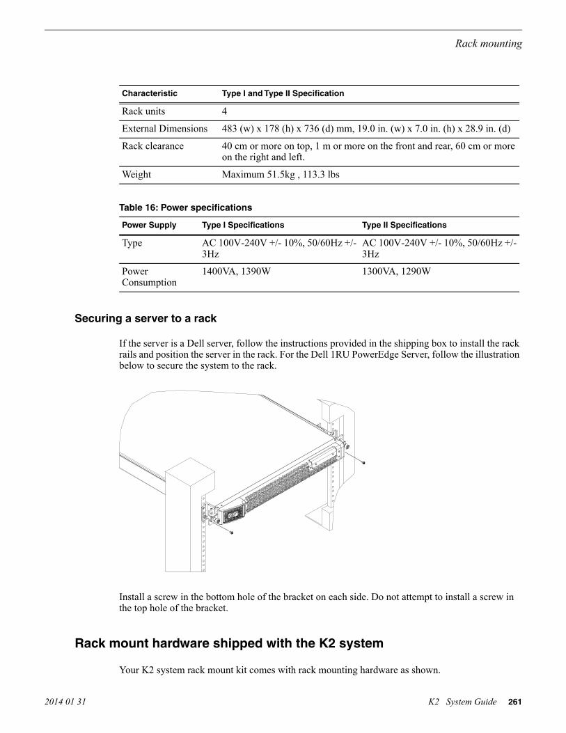
Type I and Type II SpecificationCharacteristic
4Rack units
483 (w) x 178 (h) x 736 (d) mm, 19.0 in. (w) x 7.0 in. (h) x 28.9 in. (d)External Dimensions
40 cm or more on top, 1 m or more on the front and rear, 60 cm or moreon the right and left.
Rack clearance
Maximum 51.5kg , 113.3 lbsWeight
Table 16: Power specifications
Type II SpecificationsType I SpecificationsPower Supply
AC 100V-240V +/- 10%, 50/60Hz +/-3Hz
AC 100V-240V +/- 10%, 50/60Hz +/-3Hz
Type
1300VA, 1290W1400VA, 1390WPowerConsumption
Securing a server to a rack
If the server is a Dell server, follow the instructions provided in the shipping box to install the rackrails and position the server in the rack. For the Dell 1RU PowerEdge Server, follow the illustrationbelow to secure the system to the rack.
Install a screw in the bottom hole of the bracket on each side. Do not attempt to install a screw inthe top hole of the bracket.
Rack mount hardware shipped with the K2 system
Your K2 system rack mount kit comes with rack mounting hardware as shown.
2014 01 31 K2 System Guide 261
Rack mounting
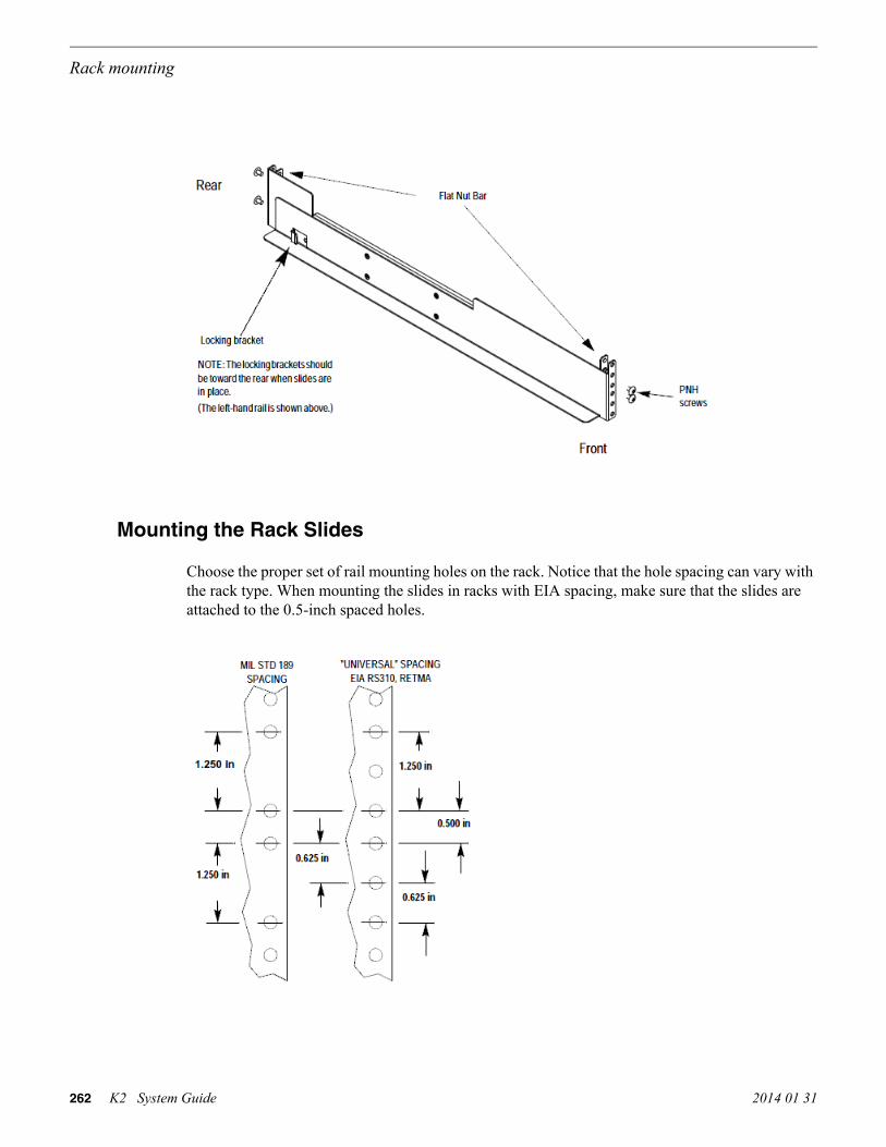
Mounting the Rack Slides
Choose the proper set of rail mounting holes on the rack. Notice that the hole spacing can vary withthe rack type. When mounting the slides in racks with EIA spacing, make sure that the slides areattached to the 0.5-inch spaced holes.
262 K2 System Guide 2014 01 31
Rack mounting

Front and rear rack rail mounting hardware is provided with the rack mount kit. Mount the railsusing the enclosed hardware. Make sure the stationary sections are horizontally aligned and arelevel, as well as parallel to each other.
Installing the K2 system on the rack mount rails
1. Pull the slide-out track section to the fully extended position.WARNING: To prevent injury, two people are required to lift the K2 system. It is too heavyfor one person to install in the rack.
WARNING: To prevent serious injury, ensure that the rack is anchored to the floor sothat it cannot tip over when the K2 system is extended out of the rack.
2. Push the chassis toward the rack until the chassis sections meet the locking bracket.3. Verify the cabinet is pushed fully into the rack.4. Insert and tighten the front panel retaining screws as shown in the previous diagram.
2014 01 31 K2 System Guide 263
Rack mounting

Making Rack Slide AdjustmentsAfter installation, binding may occur if the slide tracks are not properly adjusted. To adjust thetracks:
1. Slide the chassis out approximately 10 inches.2. Slightly loosen the mounting screws holding the tracks to the front of the rails and allow the
tracks to seek an unbound position.3. Tighten the mounting screws and check the tracks for smooth operation by sliding the chassis
in and out of the rack several times.4. Tighten the front panel retaining screws once the cabinet is in place within the rack to complete
the installation.
264 K2 System Guide 2014 01 31
Rack mounting

Trademarks and Agreements
Trademarks
Grass Valley, GV STRATUS, GV Director, K2, Aurora, Summit, ChannelFlex, Dyno, Solo,ClipStore, Infinity, Turbo, Profile, Profile XP, NetCentral, NewsBrowse, NewsEdit, NewsQ,NewsShare, NewsQ Pro, and Media Manager are either registered trademarks or trademarks ofGrass Valley USA, LLC. in the United States and/or other countries. GRASS VALLEY® is aregistered trademark. Grass Valley USA, LLC. products are covered by U.S. and foreign patents,issued and pending. Additional information regarding Grass Valley USA, LLC. trademarks andother proprietary rights may be found at www.grassvalley.com. Other trademarks and logos usedin this document are either registered trademarks or trademarks of the manufacturers or vendors ofthe associated products, such as Microsoft® Windows® operating system, Windows Media® player,Internet Explorer® internet browser, and SQL Server™. QuickTime and the QuickTime logo aretrademarks or registered trademarks of Apple Computer, Inc., used under license therefrom. AVCHDand the AVCHD logo are trademarks of Panasonic Corporation and Sony Corporation. Avid DNxHDis a registered trademark of Avid Technology, Inc., a Delaware corporation.
JPEG acknowledgment
This software is based in part on the work of the Independent JPEG Group.
2014 01 31 K2 System Guide 265

266 K2 System Guide 2014 01 31
Trademarks and Agreements

Index
A
ACpower specifications 203
AC3playout specifications 216
Access Control Listsconfiguring security on a channel 169on K2 and STRATUS 170
accounts, See securityActive Format Description, See AFDADLINK, See carrier moduleadministrative share on SiteConfig control point PC 133AES
audio connector pinouts 251digital audio specifications 209
AFDabout 218default generated values 221ingesting SDI 220output flowchart 219specifications 218storing 219with MXF and GXF file transfers 220
AMPchannels 198internationalization 198protocol settings 197transfers 198two-head player 197
ancillary data, See data trackanti-virus, See virusesAppCenter
configuring media access security 166passwords and security 164
applicationsystem overview 44
ARCabout 218output flowchart 219
architecture, See overviewsAS02
capture service 99
aspect ratioconversion specifications 217playout specifications 216
assetsnaming specifications 229
asynchronous feedsdescriptions 45
audiodigital audio specifications 209scrubbing range specifications 241
auto log on 173automation
FTP 73AVC-Intra
codec specifications K2 Summit and Solo 213transition effects specifications 242
AVC-Ultracodec specifications K2 Summit and Solo 214
AVCCAM, See H.264AVCHD, See H.264AVI, See transfer specificationsAvid DNxHD
codec specifications K2 Summit 215
B
backupsoftware and images 159
bindingLUN in Storage Utility 124LUNs for direct-connect 177LUNs on K2 Summit Transmission models 189
binsconfiguring media access security 164example of security access 162naming specifications 229nesting limitations 231
BVWprotocol settings 200
C
cablingChannelFlex 42
2014 01 31 K2 System Guide 267

cabling (continued)Ethernet requirements 60serial K2 Media server pinout 255Solo rear panel 42Summit 3G rear panel 39Summit rear panel 40
captioningdefinitions 224support specifications 226
capture serviceAS02 99export 104HotBin import 87licensing 107P2 95XML Import 92
carrier moduleidentifying Type II 36
ChannelFlexrear panel connections 42
channelsAMP 198configuring security 168configuring security for protocol control 167example of security access 163K2 Summit Transmission models 188security overview 161
charactersnot allowed in asset and bin names 230
check-o-san, See cleaning unreferenced files and movieschroma
HD support specifications 226VBI support specifications 224
CIFSP2 capture service 97proxy 191
cleaning unreferenced files and moviesStorage Utility 128
clipscorrupt with gaps 70maximum number specifications 241
closed captioningdefinitions 224
Closed CaptioningFCC requirements, EIA-708, EIA-608, DTV CC 226
codecK2 Summit and Solo specifications 211
ComExpress, See carrier module
compact flashdescription 115
Configuration Managerabout 51accessing 52restoring default settings 53saving and restoring custom settings 52
connect kitSiteConfig 133
control networksdescriptions 59
control point PCadding in SiteConfig 150assigning in SiteConfig 151
Control Point PCinstalling software 158software installed 157system requirements 245
controller logsStorage Utility 122
controller microcodedownloading in Storage Utility 129version in Storage Utility 121
convertingAFD down-convert default generated values 222AFD up-convert default generated values 221supported AFD HD to SD 223supported AFD SD to HD 223VBI data bridging specifications 22725 and 50 fps specifications 21629 and 59 fps specifications 217aspect ratio specifications 217Pinnacle to K2 clips 108
D
D10AES3MXF export 234
data bridgingVBI specifications 227
data trackDID, SDID 227definitions 224HD support specifications 226line mapping 228off-speed play range for inserting specifications 241SD support specifications 225specifications 224storing AFD 219
268 K2 System Guide 2014 01 31
Index

data track (continued)transfer compatibility with Profile XP specifications244VBI data support specifications 224
Dell serverrack mount specifications 259
deployment groupsconfiguring 154
descriptionscontrol networks 59feeds, synchronous and asynchronous 45K2 Summit/Solo 29loop through and E to E 46media (iSCSI) networks 59streaming/FTP networks 59
devicesadding with SiteConfig wizard 135
DID 227MXF export 234
direct-connectstorage description 116Fibre Channel card 175powering on K2 RAID 184setting up storage 177software install 177
DiscoveryAgentServiceSetup.msi 133disks
disabling in Storage Utility 123downloading firmware in Storage Utility 130forcing rebuild in Storage Utility 123identifying internal disks in Storage Utility 121mode pages in Storage Utility 123
Dolbyplayout specifications 216
domainsconfiguring server 2008 68
down-convert, See conversionsdrives
numbering Solo 49numbering Summit 48numbering Summit 3G 47
DTV CCFCC requirements, EIA-708, EIA-608 226
DVcodec specifications K2 Summit and Solo 212transition effects specifications 242
E
E to Edescriptions 45, 46
EBUdigital audio specifications 209
electricalspecifications 206
embedded security solutionabout 171
End User License Agreements 43environmental
specifications 204Ethernet
cable requirements 60eVTR
MXF export 234exporting
Final Cut Pro to K2 storage 83HotBIn capture service 104supported formats 232
external storage, See storage
F
FCCrequirements, EIA-708, EIA-608, DTV CC 226
featuresexternal storage 35internal storage 35K2 Solo 32K2 Solo 3G 31K2 Summit 3G 29K2 Summit first generation 30
feedsdescriptions 45
Fibre Channelcards for direct-connect 175
file interchange, See transferringfile system 127
See also media file systemFinal Cut Pro
export to K2 storage 83operation guidelines 83support 82
firewallsconfiguring server 2008 68security policies 172
firmware 130
2014 01 31 K2 System Guide 269
Index

firmware (continued)See also microcodedisk drive download in Storage Utility 130
See also microcodeformats
K2 Summit/Solo 33frames
25 and 50 fps conversions specifications 21629 and 59 fps conversions specifications 217system timing specifications 207
front panelsindicators, K2 Summit first gen 38indicators, Solo 38indicators, Summit 3G 37
FT serverrack mount specifications 260
FTPautomation 73configuration 73configuring media access security 166FTP/streaming network descriptions 59GXF and MXF 75internationalization 74Internet Explorer access 75K2 interface 70limitations media types 71nearline SAN 78regional and language settings 173security media access 73setting language 75streaming ports 64supported commands 77transfer internationalization specifications 229transfer mechanisms 72transferring
between systems 72transferring between systems 72
G
gapscorrupt clips 70
genlockspecifications 207
GPIconnecting 85K2 Summit connector pinouts 254specifications 210
GXF
GXF (continued)See also transfer specificationsfile transfers with AFD 220FTP interface 75
See also transfer specifications
H
H.264codec specifications K2 Summit 214
Harrissettings 200VDCP 200
heartbeat cable pinout 255hostnames
add to AppCenter to enable streaming 67changing 63
hosts fileswriting to devices 153in SiteConfig 152sample 66setup 65
HotBinexport capture service 104import capture service 87
house blackspecifications 207
HP ProCurve switchrack mount specifications 258
I
identifyinginternal disks in Storage Utility 121K2 Solo 37K2 Summit 3G 36K2 Summit first gen 36
illegal charactersin asset and bin names 230
imagesbackup and recovery 159
importingAS02 capture service 99compressed VBI 113HotBin capture service 87P2 capture service 95Pinnacle 108QuickTime 83supported formats 232
270 K2 System Guide 2014 01 31
Index

importing (continued)XML Import capture service 92
indicatorsfront panel, K2 Summit first gen 38front panel, Solo 38front panel, Summit 3G 37
installingSiteConfig system requirements 132software on Control Point PC 158software on K2 system 159
internal storage, See storageinternationalization
AMP 198FTP 74regional and language settings 173support specifications 229VDCP 199
iSCSImedia (iSCSI) network descriptions 59
J
java 132
K
K2 capture service, See capture serviceK2 Media Client
See also K2 systemtransfer compatibility specifications 243
See also K2 systemK2 Media Server
See also K2 systemsK2 RAID
See also RAIDrack mount specifications 260
See also RAIDK2 SAN 35
See also SANSee also K2 systemsconfiguring media access security 167FTP nearline SAN 78
See also SANSee also K2 systems
K2 Solofeatures 32identifying 37
K2 Solo 3Gfeatures 31
K2 Solo Media ServerSee also K2 Summit/Solo systems
K2 Summitidentifying 3G 36identifying first gen 36
K2 Summit 3Gfeatures 29rack mount specifications 259rear panels
Summit 3G 39K2 Summit first generation
features 30K2 Summit Production Client
See also K2 Summit/Solo systemsconnector pinouts 251
See also K2 Summit/Solo systemsK2 Summit Transmission models
channels 188features 187requirements and restrictions 189Storage Utility procedures 189
K2 Summit Transmission systemsSee also K2 Summit/Solo systems
K2 Summit/Solonetwork SiteConfig 140, 144description 29formats 33rear panels
Solo 42Summit 40
system overview 43K2 Summit/Solo systems
See also K2 systemK2 system
client software installed 157configuring network on stand-alone 63installing software 159server software installed 157
K2 Systemsupported transfer formats 232
K2 System Configuration, See K2ConfigK2Config
about 53opening 54
Kontron, See carrier module
2014 01 31 K2 System Guide 271
Index

L
languagesFTP 74internationalization specifications 229settings 173
licensingdescription 161K2 capture service 107K2 software versions 161Microsoft Windows agreements 43options 161
line mappingdata track 228
linessystem timing specifications 207
live play moderecord to play specifications 240
live streaming 191See also proxyconfigure multicast 194details 195enable 193test 194
See also proxylogin
automatic 173passwords and security 164
logscontroller logs in Storage Utility 122
loop throughdescriptions 45, 46
loopback adapter 63LTC
input output specifications 209K2 Summit connector pinouts 253
lumaHD support specifications 226VBI support specifications 224
LUNbind in Storage Utility 124unbind in Storage Utility 123
M
mapped network drive on SiteConfig control point PC133McAfee, See embedded security solution
mechanicalspecifications 205
mediacontrol system overview 44FTP limitations of types 71
media access, See securitymedia file system 127
checking for internal storage in Storage Utility 128new for internal storage in Storage Utility 127performance specifications 240SNFS software install for direct connect 177software installed 157
media networksdescriptions 59
MIB, See SNMPmicrocode 130
See also firmwarecontroller download in Storage Utility 129controller version in Storage Utility 121
See also firmwareMicrosoft Windows
system requirement 132licensing agreements 43updates 170
mix effects, See transition effectsMPEG
See also transfer specificationscodec specifications K2 Summit and Solo 212transition effects specifications 242
See also transfer specificationsMPIO
for direct-connect 177installing for direct-connect 182uninstalling for direct-connect 182
Multi-Path I/O, See MPIOmulticast
configure for live streaming 194MXF
See also transfer specificationsDID, SDID 234eVTR D10AES3 export 234file transfers with AFD 220FTP interface 75
See also transfer specifications
N
namingasset and bin length limitations 230
272 K2 System Guide 2014 01 31
Index

naming (continued)asset and bin specifications 229
NAS, See K2 Nearlinenetworks
creating with SiteConfig wizard 135requirements for SiteConfig installation 133configuration 61, 62configuring stand-alone K2 system 63connections 60considerations 63control network descriptions 59creating control network for stand-alone K2 systems136creating FTP/streaming network for stand-alone K2systems 138default settings 63he_0 64hosts files 65loopback adapter 63media (iSCSI) network descriptions 59ports 60streaming between K2 systems 64streaming/FTP network descriptions 59supported functionality 62video network performance specifications 231
new site wizardSiteConfig 135
NXCAM, See H.264
O
off-speed playrange for audio scrub specifications 241range for inserting ancillary or MPEG user dataspecifications 241
online offline modesdescription in Storage Utility 117placing K2 system into online mode 130
overviewsapplication system 44K2 Summit/Solo system 43media control and processing 44real time system 44
P
P2See also transfer specificationscapture service 95
P2 (continued)See also transfer specifications
passwordssecurity and user accounts 164
PCMplayout specifications 216
permissionsSee also securityon K2 and STRATUS 170
See also securityPinnacle
convert to K2 clips 108importing 108specifications for support 112
pinoutsAES audio connectors 251K2 Media heartbeat serial cable 255K2 Summit 3G RS-422 connectors 252K2 Summit connectors 251K2 Summit GPI connectors 254K2 Summit LTC connectors 253K2 Summit RS-422 connectors 253
PitchBlueworkflow considerations 108, 199
playingformat specifications 216record to play specifications 240
portsin firewalls 172network 60used by K2 services 46
powerAC specifications 203
powering onK2 RAID for direct-connect 184
pre-installed software 159ProductFrame, See SiteConfig
definition, See SiteConfig
Profile XPdata track transfer compatibility specifications 244transfer compatibility specifications 243VBI compatibility specifications 224
protocolsabout 197AMP 197and security 201BVW 200
2014 01 31 K2 System Guide 273
Index

protocols (continued)configuring security for media access and control ofchannels 167Harris 200internationalization specifications 229RS-422 settings 201transferring 72VDCP 198
proxy 191See also live streamingabout 191details 195format specifications 192, 215lack of support on Remote Desktop 56overview 191test 194
See also live streamingProxy
enable files 193enable stream 193
Q
QuickTimeSee also transfer specificationsimport delay 83reference files 79support 82
See also transfer specifications
R
rack mountingDell server 259, 261FT Server 260GV STRATUS devices 257HP ProCurve switch 258K2 RAID 260K2 Summit 257K2 Summit 3G 259
RAIDbind LUN in Storage Utility 124changing internal storage type RAID 0 RAID 1 126description internal drives 115description RAID 0 RAID 1 115disk controller board
description internal storage 115drive numbering Solo 49drive numbering Summit 48
RAID (continued)drive numbering Summit 3G 47drives
description internal 115forcing disk rebuild in Storage Utility 123identifying internal disks in Storage Utility 121powering on for direct-connect 184unbind LUN in Storage Utility 123
real timesystem overview 44
rear panelsChannelFlex 42K2 Summit connector pinouts 251Solo 42Summit 40Summit 3G 39
rebuilding disksStorage Utility 123
recordingcontinuous maximum length specifications 241maximum duration between specifications 241record to play specifications 240
recoverysoftware and images 159
reference filesconfiguring on SAN 80configuring on stand-alone 80QuickTime 79
reference standardtri-level sync 172
regionalsettings 173
Remote Desktopabout 56accessing 56
remote protocols, See protocolsrouter
and SiteConfig 133RS-422
connecting first gen Summit 84connecting Summit 3G 84K2 Summit 3G connector pinouts 252K2 Summit connector pinouts 253settings for protocols 201specifications first gen Summit 210specifications Summit 3G 210
274 K2 System Guide 2014 01 31
Index

S
SAMBAports in firewalls 172
samplessystem timing specifications 207
SAN, See K2 SANscrubbing
range specifications 241SCSI controller board, See disk controller boardSDI
ingesting AFD 220specifications 206
SDID 227MXF export 234
securityAccess Control Lists 169auto log on 173embedded solution 171example of access to bins 162example of access to channels 163firewall policies 172for AppCenter operations 166for channel access 168for K2 bins 164for protocol control of channels 167for protocols 201FTP 166FTP media access 73Microsoft Windows updates 170on K2 and STRATUS 170on K2 SAN 167overview 161user accounts 164virus scanning policies 172
serial cable pinout 255serial numbers
K2 Solo 37K2 Summit 3G 36K2 Summit first gen 36
server 2008 operating systemconfiguring for domain 68
servicesK2 46
sitecreating in SiteConfig 135wizard in SiteConfig 135
SiteConfigabout 56
SiteConfig (continued)adding a group 139adding standalone K2 system to system description140creating control network for stand-alone K2 systems136creating FTP/streaming network for stand-alone K2systems 138discover standalone K2 system 142main window 57managing stand-alone K2 systems 131Network Configuration Connect Kit 133opening 57ProductFrame Discovery Agent 133
SNFS, See media file systemSNMP
MIB specifications 246software
SiteConfig on K2 SAN 155backup 159configuring deployment groups 154install for direct connect 177installed on devices 157installing on Control Point PC 158installing on K2 system 159pre-installed 159
spywarescanning policies 172
startupfirst time 43
statussubsystem in Storage Utility 121
storagedirect-connect 116external
features 35internal 115
features 35Storage Utility
bind LUN 124changing internal storage RAID type 126checking internal storage media file system 128cleaning unreferenced files and movies 128controller logs 122controller microcode version 121description 117description online offline modes 117disabling disk 123disk mode pages 123
2014 01 31 K2 System Guide 275
Index

Storage Utility (continued)downloading controller microcode version 129downloading disk drive firmware version 130forcing disk rebuild 123identifying internal disks 121new internal storage media file system 127opening independently 119opening through AppCenter 118overview 120procedures for K2 Summit Transmission models 189subsystem status 121unbind LUN 123
streamingSee also live streamingadd hostnames to AppCenter 67between K2 systems 64he_0 64
See also live streamingstreaming/FTP networks
descriptions 59stripe group
description 115subtitles, See captioningswitch Ethernet
and SiteConfig 133synchronous feeds
descriptions 45system
creating in SiteConfig 135system timing
specifications 207
T
TCPports in firewalls 172
teletextcaptioning support specifications 226definitions 224
testproxy, live streaming 194, 195
timecodeLTC input output specifications 209VITC input output specifications 210
timingsystem specifications 207
transferringAMP 198automatically or mechanically 72
transferring (continued)AVI specifications 235compatibility with K2 Media Client specifications243compatibility with Profile XP specifications 243file format specifications 232files with AFD 220GXF specifications 232MPEG specifications 238MXF specifications 233P2 specifications 239QuickTime specifications 236QuickTime video and key import specifications 237VDCP 199video network performance specifications 231WAV specifications 240
transition effectssupported formats specifications 242
tri-level sync 172two-head player
AMP 197VDCP 199
U
UDPports in firewalls 172
unbindingLUN in Storage Utility 123
UnicodeAMP 198VDCP 199
up-convert, See convertingupdates
Microsoft Windows 170upgrade software
SiteConfig on K2 SAN 155user accounts, See security
V
V driveRAID drive 115
VBIdata bridging specifications 227compressed VBI import 113data support specifications 224definitions 224HD support specifications 226
276 K2 System Guide 2014 01 31
Index

VBI (continued)Luma Chroma support specifications 224SD support specifications 225specifications 224
VDCPHarris 200internationalization 199protocol settings 198transfers 199two-head player 199
video and key, See QuickTime import specificationsVideo Monitor
lack of support on Remote Desktop 56video network
performance specifications 231views
front panel, K2 Summit first gen 38front panel, Solo 38front panel, Summit 3G 37Solo rear panel 42Summit 3G rear panel 39Summit rear panel 40
virusesembedded security solution 171scanning policies 172
VITCinput output specifications 210
VIXIA, See H.264
W
WAV, See transfer specificationsWindows, See Microsoft WindowsWindows Remote Desktop, See Remote Desktopwizard
new site SiteConfig 135
X
XMLsystem requirement 132Configuration Manager 51import capture service 92
2014 01 31 K2 System Guide 277
Index

278 K2 System Guide 2014 01 31
Index