K-HB-0053EN PK-HCS-2020 V2-0
208
Communications systems Product catalogue
Transcript of K-HB-0053EN PK-HCS-2020 V2-0

Communications systems
Product catalogue


K-HB-0053EN Communications systems Product catalogue 2020/2021 · V 2.0 3
Table of contents
1 General .......................................................................................................................... 4
2 General safety notes ...................................................................................................... 6
3 Visocall IP call systems.................................................................................................... 83.2 Answering units................................................................................................................................................... 183.3 Patient handsets .................................................................................................................................................. 253.4 Connection modules .......................................................................................................................................... 363.5 Terminals.............................................................................................................................................................. 543.6 Intercom terminals ............................................................................................................................................. 653.7 Pushbuttons ......................................................................................................................................................... 703.8 Call indications .................................................................................................................................................... 933.9 Hardware interfaces............................................................................................................................................ 1003.10 Radio components.............................................................................................................................................. 1133.11 Call devices for special applications................................................................................................................. 1203.12 Central system components .............................................................................................................................. 1253.13 Installation accessories ....................................................................................................................................... 1383.14 Software licences................................................................................................................................................. 145
4 TV sets ............................................................................................................................1474.1 Philips TV sets..................................................................................................................................................... 1484.2 Samsung TV sets................................................................................................................................................. 151
5 Multimedia devices.........................................................................................................154
6 Visoopt emergency call systems .....................................................................................1596.1 Product overview................................................................................................................................................ 159
7 Securwatch real-time localisation....................................................................................1667.1 Networked systems............................................................................................................................................. 1667.2 Single-door-system ............................................................................................................................................. 184
8 Power supply .................................................................................................................1888.1 Power supplies..................................................................................................................................................... 1888.2 Uninterruptible power supply ........................................................................................................................... 193
Product index.................................................................................................................... 200By article number .......................................................................................................................................................... 200By type designation....................................................................................................................................................... 203

General
4 Communications systems Product catalogue 2020/2021 · V 2.0 K-HB-0053EN
1 GeneralSchrack Seconet security systems are developed in Austria, produced in Germanyand incorporate both state-of-the-art technology and the latest scientific develop-ments, while meeting all the latest applicable standards (European standards, re-quirements of European testing and certification bodies etc.). Schrack Seconet fre-quently cooperates with technical universities and international companies, as well aswith testing and certification bodies, fire prevention centres and fire brigade associ-ations, so that products can be constantly optimized and adapted to meet new de-mands.The high quality of Schrack Seconet products is ensured using an ISO 9001 ap-proved Quality Assurance system throughout the company's activities (from devel-opment through production and sales processes through installation to customerservice).Considerable attention is paid in the development of products towards the separa-tion of materials used, reusability, disposal and recycling to ensure that materialswere processed in an as environmentally sound way as possible.
To this documentThese descriptions and technical specifications correspond to the status as of the date of publication. SchrackSeconet reserves the right to make modifications, in particularly where they are justified as a result of technologicalprogress. In the course of continual development, the products delivered may differ optically from shownproducts. Information which is not contained in this document can be requested at any time from one of our of-fices.The original of this document was written in German. Editions in other languages may include errors due totranslation, Schrack Seconet assumes no liability for these.The design of this document is subject to copyright law. The printing and the copying of contents (e.g. texts, im-ages, photos) including extracts in any type of media (such as print, CD-ROM, internet) is only permitted withSchrack Seconet explicit written consent. For printing errors and obvious errors no liability is accepted. For en-quiries and orders, please indicate article numbers.
Explanation of symbols
Important notes in this document are identified by the following symbols. Failure to observe these instructionsmay result in malfunction of the security systems or in property or personal injury.
NOTE
Contains notices to help you use the product or system more effectively and easily. Usage is optional
CAUTION
Indicates a danger, the non-observance of which may result in financial loss or damage to property.
Electrical / electronical devices and batteries
Electrical and electronical devices or batteries may not be disposed of in household rubbish. Usedelectrical and electronical devices as well as batteries should be returned free of charge after use to thevendor or to the designated places for returning them (e.g. communal collection points or in shops).

General
K-HB-0053EN Communications systems Product catalogue 2020/2021 · V 2.0 5
Information about the structure of the catalogue
Introduction product groupsThe product groups are divided into chapters. Each chapter begins with a description of the product group andthe possible structure of products. The connection options for the system connection are shown in a diagram.
Product overviewThe product overview is an overview of the available functions for each product. For each available function it isshown in which product this function is available.
Article descriptionThe articles are described with the information shown:
No.: 21-1031502-01
Connection module with two red Intellifix sockets for installation in a mediaduct or for wall-mounting.For surface mounting, the corresponding APA-2 surface-mounted housing isrequired; for countersunk mounting, a double connection box installed in thewall must be provided for. Generally installed in patient rooms, near the bed inthe vicinity of the headboard.
Red Intellifix sockets for connecting two BT-IP pear pushbuttonsAutomatic input monitoring of the Intellifix socket with automatic callreleasing (disconnection call)
System compatibility:Interfaces: System connection:
Red Intellifix socket:
Installation: Protection class: Ambient temperature: Relative air humidity: Case: Dimensions: Weight:
Visocall IP
2 × RJ-12 sockets for connection to the basicinterface of a ZTD-B, ZTD-B-L, ZT-B, ZE-B or SM-B (with power supply)2 × RJ-45 sockets with release mechanism(basic interface with power supply)Surface mounted, countersunk or in a serviceductIP 32, VDE 0834 Environmental class II+5 °C to +40 °Cup to 95% without condensationPlastic ABS, white RAL 901683 × 160 × 41 mm (H×W×D)97 g
Connection module SM2-B
nn
Technical data
Picture and article number
Equipment features
Label and product typeGeneral short description and installation
information
Product list and accessoriesAt the end of a chapter all products and variants as well as the respective accessories and spare parts are listed.The overview table contains descriptions, the product types and the article numbers for ordering products.

General safety notes
6 Communications systems Product catalogue 2020/2021 · V 2.0 K-HB-0053EN
2 General safety notesThe planning of security systems as well as the installation, commissioning and maintenance of products and thesystems which they form required specialist expert knowledge, and therefore may only be undertaken by speciallytrained experts. The product-specific training of staff members must be carried out by Schrack Seconet or byskilled personnel who have been specifically authorised to carry out this duty by Schrack Seconet.Schrack Seconet explicitly state, that security systems must be periodically maintained by certified and qualifiedpersonnel in accordance with the relevant standards (such as ÖNORM F 3070, VDE 0834), in order to maintainthe functional and protective scope in the long term. For servicing and maintenance work on fire alarm systems,the currently valid regulations of the country in which the system is being operated shall apply.In addition, the relevant country-specific regulations and guidelines for the planning, installation, service andmaintenance must be adhered to and complied with. Damage and consequential damage caused by interventionsor changes to products and their improper handling are excluded from liability. The same is also true for inappro-priate storage of items and other detrimental external factors.

Visocall IP call systems
K-HB-0053EN Communications systems Product catalogue 2020/2021 · V 2.0 7
The most important thing: the safety of patientsCall systems in hospitals are primarily there to support people inemergency situations and to offer them assistance quickly. Reliab-ility and fault-free operation is the highest priority fo Visocall IP.
3 Visocall IP call systems

Visocall IP call systems · System overview
8 Communications systems Product catalogue 2020/2021 · V 2.0 K-HB-0053EN
3 Visocall IP call systems
3.1 System overview· System overview
Visocall IP brings together care, information, service, organisation and billing in hospitals using a common func-tional platform. IP-based network technology forms the economical, secure and extendible structure for all func-tions and services in the care sector.The integration of several systems on a shared platform offers entirely new possibilities, increases security and re-duces costs. The most important performance characteristics of Visocall IP at a glance:
n Nurse calln VoIP telephonyn Multimedia, TV and radion Internet and Intranetn Room control from the bed (lighting, blinds and TV)n Care data loggingn Announcements and speech connections to patients and staffn Mobile support for staff: Forwarding of alarms, calls, fault messages etc. to mobile devices e.g.: smart
phones, tablets, DECT and WLAN telephones.n Standardised interfaces for exchanging data and for communications connections between different sys-
tems (e.g. mobile devices and databases)
Conforming with VDE 0834Visocall IP is certified in accordance with VDE 0834 and therefore fulfils the highest requirements for securityand reliability.
A fail-safe systemVisocall IP is not dependent on the system's backbone: The intelligent system elements also perform their taskwithout a network or a server.
Automatic fault detectionVisocall IP monitors itself: System faults are automatically detected and are forwarded immediately to the respons-ible member of the technical staff. Detailed fault descriptions are made available immediately to mobile devices viapagers, DECT, smart phones or tablets.Visocall IP offers affordable installation and operation. The system is based on a topology and is realised with astandardised cable for data, speech and multimedia. This provides for versatile functions and options. At the sametime the call system is easy to plan.
Deployment state-of-the-art network technologyAffordable standard network technology is used for Visocall IP. Existing network structures can also be used.
Modular system: incremental structure optionsAdditional functions like the solution for protecting patients with dementia, care data logging or patient entertain-ment can also be activated at any time at a later stage, and ongoing operation is not affected in any way.
Simple to renovate and revitaliseExisting cable ducts can be reused, as a single network cable does not take up much space. Older Schrack Seconetsystems can also be functionally integrated into the Visocall IP platform – thereby vindicating previous invest-ments.

Visocall IP call systems · System overview
K-HB-0053EN Communications systems Product catalogue 2020/2021 · V 2.0 9
Visocall IP lowers your operating costsThanks to the simple structure used, expense for servicing and maintenance can be minimized.
Plug & play: Plug and socket connections and pluggable modulesWhen installing or replacing modules there is nothing that can go wrong. What using to require being screwed inis now available as a plug-in module. This adds up to plug & play without time-consuming programming or con-figuration.
Intellifix – self-disconnecting plugsThe plug yields in the event of tensile loads from any direction. Cables do not tear,sockets are protected, and the most common causes of repair can be avoided. Intel-lifix is also exceptionally cheap and is included on every system device as standard.
Centralised firmware uploads and software updatesNew functions, software and updates for all devices can be uploaded from a central location.
Remote diagnosis and remote accessThe, Service- responsible for maintenance, and check the overall state of the system from any location and deploytechnicians in a targeted fashion.

Visocall IP call systems · System overview
10 Communications systems Product catalogue 2020/2021 · V 2.0 K-HB-0053EN
Overview of components
CENTRAL SYSTEM COMPONENTS
SYSTEM MAINCOMPONENTS
SYSTEM SWITCHESBACKBONE SWITCHES SYSTEM SWITCHES SOUND INTERFACE
System switchL4-SWI9-GBIT
Sound interface SDI
Sound interface Controller SIC
Core switch SRV-SWITCH
Ward/core switch ST-SWITCH
Ward switch HP2530-24-IP
C-SW
SC-SW
S-SW
Management Center MC-IP
Management Center MC-IP-D
Logical Delivery Point LDP
MC-IP
MC-IP-D
LDP
HARDWARE INTERFACES
IP INTERFACE IO-BUS INTERFACE
TV interface TVI-IP
Connection distributor VTXT-IP
Connection distributor VDVI-IP
Multi sound 4 interface MS4-I
Input/output module IO-M
Input/output module IO-M-P
Latching relay SSR-IO
Room electronics ZE-B
POWER SUPPLY
POWER SUPPLY UNITS UPS
Power supply 5A REDIN120-24
Power supply 5A REDIN240-24
Power supply 5A REDIN480-24
Power supply VDE083424V/10A CP10.241-M1
UPS Eaton 5PX 1500I RT2HE 5PX1500IRT
UPS Eaton 5PX EBM 48V RT2HE 5PXEBM48RT
SecoLOG IP emergency power supply SECOLOG IP EPS
CALL INDICATIONS
OVERDOORLIGHTS
LARGE TEXT INDICATORS
TEXT TERMINALS ON-SCREENINDICATORSLight module LM-IO
Light module LM-B Text terminal TXT
Text terminal TXT-W
Text terminal TXT-2W
Text terminal TXT-D
Text terminal TXT-2D
Monitors or TV sets used forindicating calls via VDVI-IP.
SOFTWARE LICENCES
SOFTWARE LICENCES SYSTEM LICENCES SYSTEM EXTENSIONS LICENCES INTERFACES
LICENCES BILLING
SOFTWARE TOOLS FOROPERATORS
SOFTWARE TOOLS FORTECHNICIANS
Software licence alarm server SWP-IP/AS
Software licence fire alarm system SWP-IP/BMZ
Software licence dementia protection system SWP-IP/DESO
Software licence ESPA interface SWP-IP/ESPA
Software licence internet server SWP-IP/WEB
Software licence KNX/EIB interface SWP-IP/KNX
Software licence mobile telephone end devices SWP-IP/MP
Software licence OPC server SWP-IP/OPC
Software licence telecommunications system SWP-IP/TK
Software licence internet access charges SWP-VTIP/ONLINE
Software licence PAT 50 SWP-VTIP/PAT50
Software licence PAT 100 SWP-VTIP/PAT100
Software licence PAT 300 SWP-VTIP/PAT300
Software licence telephone billingSWP-VTIP/TEL
Software licence VISOTAX IP admin SWP-VTIP/ADMIN
Software licence VT IP Cash Terminal SWP-VTIP/CT
Software licence VT IP Cash Till Monitor SWP-VTIP/CTM
Software licence TV billing SWP-VTIP/TV
Software licence Audio Manager SWP-IP/AM
Software licence event database SWP-IP/EDB
Software licence MMC redundancy SWP-IP/MMC-R
Software licence patient management SWP-IP/PV
Software licence Secocare Data SWP-IP/CD
Software licence Secocare Data Erweiterung SWP-IP/CD-E
Software licence ward control panel SWP-IP/SLS
Software licence ward control panel extension SWP-IP/SLS-E
Software licence System Monitor SWP-IP/MON
Software licence telephone book function SWP-IP/PBF
Software licence centralised control panel SWP-IP/ZLS
Software licence centralised control panel extension SWP-IP/ZLS-E
VCIP Application Kit V 7.0 SWP-IP/AK-7.0
Admin
Audio Manager
Card Admin
Care Card Admin
Cash Terminal
Cash Till Monitor
Control Panel
System Monitor
Visotax IP Admin
Config
Debug Monitor
OPC Config
Routing Suite Admin
Service Center
Setup Loader
Update
WPLA
System structure
Signalling

Visocall IP call systems · System overview
K-HB-0053EN Communications systems Product catalogue 2020/2021 · V 2.0 11
ANSWERING UNITS
Centralised control panelA control panel is a software application (software licence centralised control panel) installed on acomputer connected to the network of the call system.
Ward control panel
Staff Terminal ST-TOUCH
A control panel is a software application (software licence ward control panel) installed on a computerconnected to the network of the call system.
PUSHBUTTONS
IO-BUSPUSHBUTTONS
BASICPUSHBUTTONS
Call pushbutton RTB-IO
Call and service pushbutton SRT-IO
Doctor call pushbutton ART-IO
Cancel pushbutton AT-IO
Presence pushbutton AWT-IO
Call/cancel pushbutton piezo RAT-P-IO
Call/cancel pushbutton RATB-IO
Doctor call/cancel pushbutton piezoARAT-P-IO
Pull cord call switch ZTB-IO
Pull cord call switch/cancelpushbutton ZRAT-IO
Pneumatic call switch PT-IO
Call pushbutton RTB-B
Doctor call pushbutton ART-B
Cancel pushbutton AT-B
Call/cancel pushbutton RATB-B
Pull cord call switch ZRTB-B
Pull cord call switch/cancelpushbutton ZRAT-B
Pneumatic call switch PT- B
TERMINALS
COMMUNICATIONTERMINALS
ROOM TERMINALS RFID TERMINALS
Communications terminal KMT
Communications terminal KMT-L
Room terminal ZTD-B
Room terminal ZTD-B-L
Room terminal ZT-B
RFID terminalRFID-IO-FRT
RFID terminalRFID-IO
CONNECTION MODULES
DIAGNOSTIC MODULES CONNECTION MODULES ACCESSORIES
IP CONNECTIONMODULES
IO-BUS CONNECTIONMODULES
BASIC CONNECTIONMODULES
Connection moduleSM
Connection moduleSM-MMC
Connection moduleSM-S
Connection moduleSM-B
Connection moduleSMU-B
Connection moduleSM1-B
Connection moduleSM2-B
Connection moduleSM1-B-S
Diagnostic adapter AD-DIA
Diagnostic connectionsDSTK-W-VCIP
Blue Intellifix socket for IPcomponents (patient terminals, BT-IP,ST-TOUCH)
Red Intellifix socket for basic components (BT-B)
MULTIMEDIA
SYSTEM TV
MULTIMEDIA TERMINALS
Room TV
Beds TV
MediPaD MP16
MediPaD MP13
MediPaD MP10
PATIENT HANDSETS
PATIENT TERMINALS PEARPUSHBUTTONS
Patient terminal PAT
Patient terminal PAT-E
Patient terminal PAT-L
Pear pushbutton
BT-IP
Pear pushbutton
BT-B
RADIO COMPONENTS
RADIO RECEIVER RADIO TRANSMITTER
Radio receiverVR6-5
Radio receiverVR6-5 DIN-NT
CareMat A01T-L869
CareMat B01T-L869
Combination radio transmitter F-VMS-869
Radio pneumatic ball-type button F-PS-869
Radio Pneumatic transmitter PS3
Radio call pushbutton F-RTS-869
Radio universal transmitter F-VMUS-869
Radio pull cord call switch F-ZS-869
MediPad cushion transmitter F-MP-869
Universal radio pull cord call switch UF-ZS-869
arioFon noise detector F-GSM-869
VarioMent Plus wandering detection system F-WLS-869
CALL DEVICES FOR SPECIALAPPLICATIONS
Noise monitor SW-NT-OK
CareMat A01C
CareMat B01C
INTERCOM TERMINALS
Intercom Terminal ICT-IP
Visitor intercom terminal is made upof the system function visitorintercom terminal an a staffterminal.
operated by staff Connection modules operated by patients
Diagnostic module DM-IO
Diagnostic module DMU-IO
Diagnostic module DM1-IP
Connection module SMF-B

Visocall IP call systems · System overview
12 Communications systems Product catalogue 2020/2021 · V 2.0 K-HB-0053EN
System structure
IP components
TVI-IP VTXT-IP VDVI-IP
System TV
Text terminals
On-screen indicators
MultimediaTerminal
DOCTORWard 5 Room 1Bed call bed 3Ward 4 Room 5
Control panel
Event database
Visotax IP
Secocare Data
Audio Manager
System Monitor
Patient management
Secocare Assist
Audio
BillingStaff mobile
WLAN
Video streaming
ManagementCenter
Positioning SystemRTLS
Alarm serverMobile device
IP telephone system
DECTtelephone
Time server
MS4-I
ExternalAudio system
SWI9
Ward switch
PAT PAT-E PAT-L BT-IP
AD-DIA
SM-MMC
DM1-IP
SM
ST-TOUCH
KMT KMT-L
ICT-IP
SM-S
Patient call

Visocall IP call systems · System overview
K-HB-0053EN Communications systems Product catalogue 2020/2021 · V 2.0 13
IO-BUS components Basic components
Radio components
RT-IO
AWT-IO
ART-IO
ARAT-P-IO
SRT-IO
ZTB-IO
PT-IO
ZRAT-IO
AT-IO
RATB-IO
RAT-P-IO
SSR-IO
IO-M
IO-M-P
ZTD-B
ZTD-B-L
ZT-B
ZE-B
SM-B
SMU-B
DMU-IO
DM-IO
RFID-IO
RFID-IO-FRT
LM-IO
SM2-B
SM1-B-SBT-B
SM1-Bmax. 50 m to basic components
RT-B
ZRTB-B
PT-B
AT-BZRAT-B
Medicaldevices
ART-B RATB-B
LM-B
SMF-B
VR6-5
VR6-5 DIN-NTPS3
F-PS-869
F-VMS-869
F-ZS-869
F-RTS-869F-MP-869A01T-L869 and
B01T-L869

Visocall IP call systems · System overview
14 Communications systems Product catalogue 2020/2021 · V 2.0 K-HB-0053EN
Explanation of terms/glossary
2 × MOPP 2 × Means Of Patient Protection: Special safety measure for minimising the risk ofelectric shock for patients.
Answering button Communications terminal button taking answerable calls and for making announce-ments.
Monitor lock To establish a speech connection, the selected call partner must actively accept thecall by pressing a button.
Cancel button Button for deactivating calls of a predefined category. Cancel buttons can either begreen (care staff) or blue (medical staff). If a call is released in an adjoining room,for which a cancel button has been allocated, the status LED of the cancel buttonwill light up. This will show arriving staff which button must be used to cancel thecall. Pressing the button will cancel the call and the status LED will go out. Actuat-ing cancel button will neither set nor deactivate presences. Other than is the casewith presence buttons, the status LED of a cancel button will not light up when thebutton is pressed repeatedly.
Disconnection call Call automatically released when disconnecting a patient handset. The call must beacknowledged by connecting the patient handset and carrying out a subsequentfunction test (actuation of the flashing call button).
Presence button Button for setting and deactivating presences of a predefined category. Presencebuttons can either be green (care staff), yellow (service staff) or blue (medical staff).By pressing the device once, a presence of the relevant category will be set and thestatus LED next the button will light up (parallel indication to light module). The setpresence will cancel calls addressed to this staff category. Pressing the button againwill deactivate the presence and the status LED will go out.
Doctor call Where the presence is set by a care staff, a doctor call can be released by pressingthe doctor call button.
Doctor call button A doctor call button triggers a call, addressed to the medical staff. The button isblue with a white staff of Aesculapius. Regardless of the set presence, one of the fol-lowing calls can be released:
n Doctor call (green presence + doctor call button)n Heart alarm (yellow presence + doctor call button)
Backbone switch Collective term for core switches, ward/core switches and ward switches. Systemswitches form an own product group and do not count as backbone switches.
Beds TV The system TV installed at each individual bed and can only be controlled by thebed’s patient terminal.
On-screen indications Monitors or TV sets used for indicating calls.
Visocall IP call systems · System overview
K-HB-0053EN Communications systems Product catalogue 2020/2021 · V 2.0 15
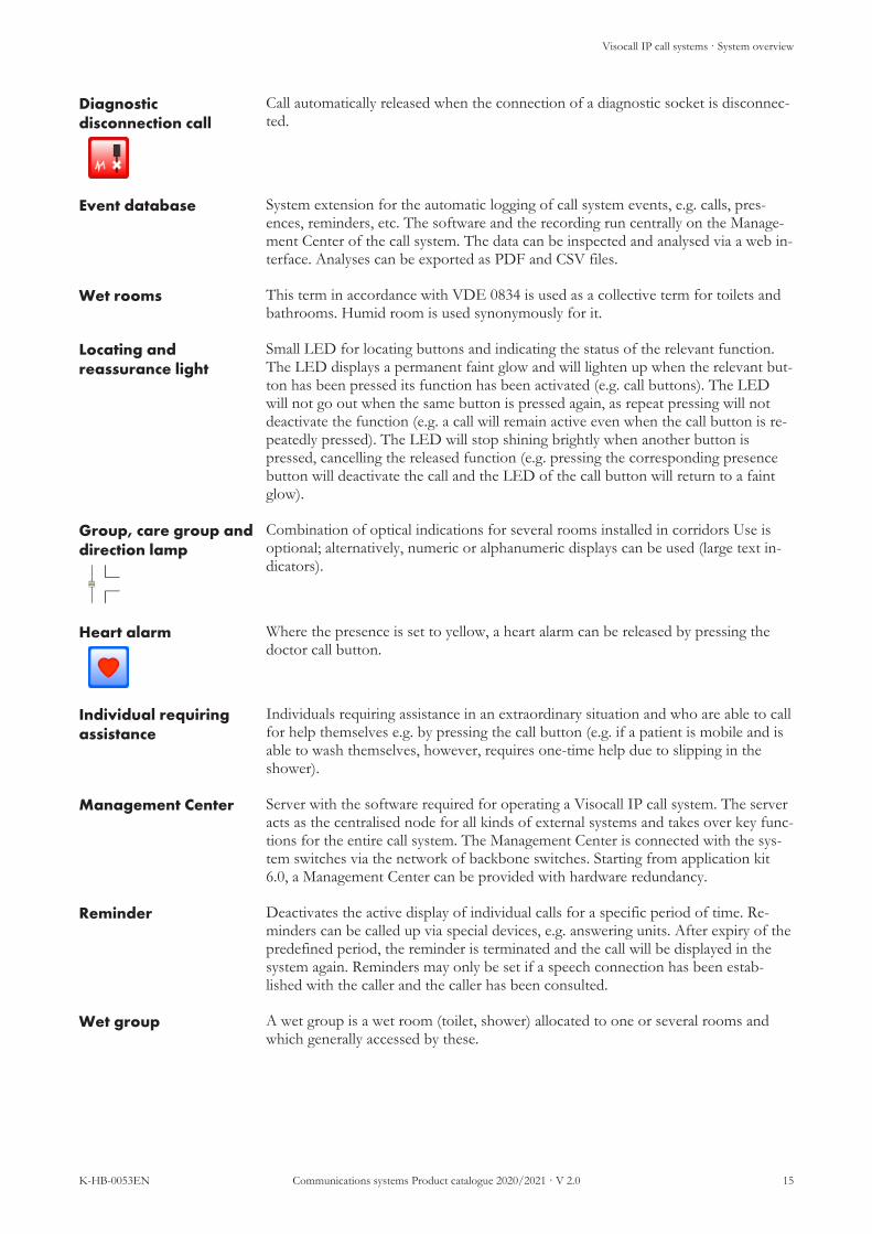
Diagnosticdisconnection call
Call automatically released when the connection of a diagnostic socket is disconnec-ted.
Event database System extension for the automatic logging of call system events, e.g. calls, pres-ences, reminders, etc. The software and the recording run centrally on the Manage-ment Center of the call system. The data can be inspected and analysed via a web in-terface. Analyses can be exported as PDF and CSV files.
Wet rooms This term in accordance with VDE 0834 is used as a collective term for toilets andbathrooms. Humid room is used synonymously for it.
Locating andreassurance light
Small LED for locating buttons and indicating the status of the relevant function.The LED displays a permanent faint glow and will lighten up when the relevant but-ton has been pressed its function has been activated (e.g. call buttons). The LEDwill not go out when the same button is pressed again, as repeat pressing will notdeactivate the function (e.g. a call will remain active even when the call button is re-peatedly pressed). The LED will stop shining brightly when another button ispressed, cancelling the released function (e.g. pressing the corresponding presencebutton will deactivate the call and the LED of the call button will return to a faintglow).
Group, care group anddirection lamp
Combination of optical indications for several rooms installed in corridors Use isoptional; alternatively, numeric or alphanumeric displays can be used (large text in-dicators).
Heart alarm Where the presence is set to yellow, a heart alarm can be released by pressing thedoctor call button.
Individual requiringassistance
Individuals requiring assistance in an extraordinary situation and who are able to callfor help themselves e.g. by pressing the call button (e.g. if a patient is mobile and isable to wash themselves, however, requires one-time help due to slipping in theshower).
Management Center Server with the software required for operating a Visocall IP call system. The serveracts as the centralised node for all kinds of external systems and takes over key func-tions for the entire call system. The Management Center is connected with the sys-tem switches via the network of backbone switches. Starting from application kit6.0, a Management Center can be provided with hardware redundancy.
Reminder Deactivates the active display of individual calls for a specific period of time. Re-minders can be called up via special devices, e.g. answering units. After expiry of thepredefined period, the reminder is terminated and the call will be displayed in thesystem again. Reminders may only be set if a speech connection has been estab-lished with the caller and the caller has been consulted.
Wet group A wet group is a wet room (toilet, shower) allocated to one or several rooms andwhich generally accessed by these.
Visocall IP call systems · System overview
16 Communications systems Product catalogue 2020/2021 · V 2.0 K-HB-0053EN
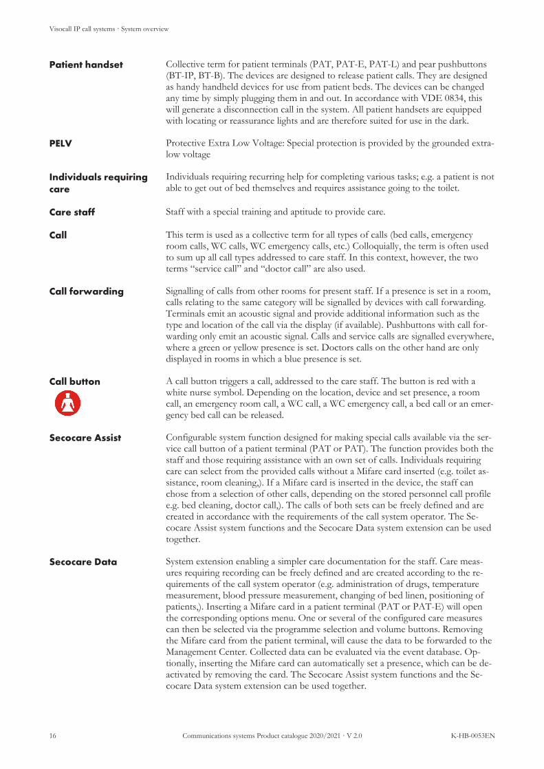
Patient handset Collective term for patient terminals (PAT, PAT-E, PAT-L) and pear pushbuttons(BT-IP, BT-B). The devices are designed to release patient calls. They are designedas handy handheld devices for use from patient beds. The devices can be changedany time by simply plugging them in and out. In accordance with VDE 0834, thiswill generate a disconnection call in the system. All patient handsets are equippedwith locating or reassurance lights and are therefore suited for use in the dark.
PELV Protective Extra Low Voltage: Special protection is provided by the grounded extra-low voltage
Individuals requiringcare
Individuals requiring recurring help for completing various tasks; e.g. a patient is notable to get out of bed themselves and requires assistance going to the toilet.
Care staff Staff with a special training and aptitude to provide care.
Call This term is used as a collective term for all types of calls (bed calls, emergencyroom calls, WC calls, WC emergency calls, etc.) Colloquially, the term is often usedto sum up all call types addressed to care staff. In this context, however, the twoterms “service call” and “doctor call” are also used.
Call forwarding Signalling of calls from other rooms for present staff. If a presence is set in a room,calls relating to the same category will be signalled by devices with call forwarding.Terminals emit an acoustic signal and provide additional information such as thetype and location of the call via the display (if available). Pushbuttons with call for-warding only emit an acoustic signal. Calls and service calls are signalled everywhere,where a green or yellow presence is set. Doctors calls on the other hand are onlydisplayed in rooms in which a blue presence is set.
Call button A call button triggers a call, addressed to the care staff. The button is red with awhite nurse symbol. Depending on the location, device and set presence, a roomcall, an emergency room call, a WC call, a WC emergency call, a bed call or an emer-gency bed call can be released.
Secocare Assist Configurable system function designed for making special calls available via the ser-vice call button of a patient terminal (PAT or PAT). The function provides both thestaff and those requiring assistance with an own set of calls. Individuals requiringcare can select from the provided calls without a Mifare card inserted (e.g. toilet as-sistance, room cleaning,). If a Mifare card is inserted in the device, the staff canchose from a selection of other calls, depending on the stored personnel call profilee.g. bed cleaning, doctor call,). The calls of both sets can be freely defined and arecreated in accordance with the requirements of the call system operator. The Se-cocare Assist system functions and the Secocare Data system extension can be usedtogether.
Secocare Data System extension enabling a simpler care documentation for the staff. Care meas-ures requiring recording can be freely defined and are created according to the re-quirements of the call system operator (e.g. administration of drugs, temperaturemeasurement, blood pressure measurement, changing of bed linen, positioning ofpatients,). Inserting a Mifare card in a patient terminal (PAT or PAT-E) will openthe corresponding options menu. One or several of the configured care measurescan then be selected via the programme selection and volume buttons. Removingthe Mifare card from the patient terminal, will cause the data to be forwarded to theManagement Center. Collected data can be evaluated via the event database. Op-tionally, inserting the Mifare card can automatically set a presence, which can be de-activated by removing the card. The Secocare Assist system functions and the Se-cocare Data system extension can be used together.

Visocall IP call systems · System overview
K-HB-0053EN Communications systems Product catalogue 2020/2021 · V 2.0 17
SELV Safety Extra Low Voltage: Special protection is provided by grounded extra-lowvoltage
Service staff Staff carrying out more basic activities without care measures.
Service call button Triggers a service call, addressed to the service staff. The button is grey with a cupsymbol. If the Secocare Assist system function is configured, this button can beused to release further calls.
Speech connection Audio connection between two devices of the call system, established via the callsystem network.
Status LED Small LED next to a button, displaying whether the relevant function is active. TheLED is generally off and will light up as long as the relevant function is active. Theexact LED behaviour depends on the connected button.
System TV A TV set connected to the call system for showing TV programmes which can becontrolled via the patient terminals. Can be provided as bed TV or room TV.
Distributed alarmsystem
Both interfaces of the system (call system) as well as the alarm transmission are de-signed to ensure the reliable transmission of alerts. All components involved inalarm transmission and alarm indication are automatically monitored. Malfunctionsand errors generate technical alarms and are displayed to the staff.
Distributedinformation system
Interfaces of the system (call system) and the transmission of information are notdesigned in terms of a distributed alarm system. The system merely transmits in-formation without monitoring the transmission or display. The transmission of thealarm signals may not be relied on.
Room TV System TV installed in a room and providing entertainment for several patients. TheTV set can be controlled by more than one patient terminal.
Overdoor lights A device for the optical indication of calls, presences and reminders allocated to aroom. It is imperative that the overdoor light is installed in the direct vicinity of allrooms with call options. The lamps must be clearly detectable from a longer dis-tance.

Visocall IP call systems · Answering units
18 Communications systems Product catalogue 2020/2021 · V 2.0 K-HB-0053EN
3.2 Answering units· Answering units
According to VDE 0834-1:2016-06, a answering unit is a device to indicate and answer calls, to switch them off by means ofremote control, and to indicate information on the presence of one or several organisational groups. For Visocall IP call systemsthis definition apply to the staff terminal and the control panel.System connection is implemented as set out for a Staff Terminal to an IP connection module or for a controlpanel to a backbone switch or at port 8 of a system switch.
Answering units Backbone switches
System switch
IP connection module
Centralised controlpanel
Ward control panel
ST-TOUCH
SM SM-MMC SM-S
L4-SWI9-GBIT
SRV-SWITCH
ST-SWITCH
HP2530-24-IP
C-SW
SC-SW
S-SW
EMOSAFE EN-7DE
Illustration 1: Connection scheme answering units

Visocall IP call systems · Answering units
K-HB-0053EN Communications systems Product catalogue 2020/2021 · V 2.0 19
Product overview
Features ST-T
OU
CH
Cent
ralis
edco
ntro
l pa
nel
Wa
rd c
ont
rol
pa
nel
An overview of all events in a ward • • •An overview of all events in several wards •Graphic user interface with building layout • •Adjustable layout of the user interface • •Announcements • • •Establishment of speech connections to other components of the call sys-tem
• • •
Integrated IP telephone •Radio operation •Call forwarding, call answering, setting reminders • • •Setting presences, releasing calls • • •Control of interconnections and centralisation of the ward • • •Management of care groups and call prioritisation of individual beds • • •

Visocall IP call systems · Answering units
20 Communications systems Product catalogue 2020/2021 · V 2.0 K-HB-0053EN
Staff Terminal ST-TOUCH
No.: 21-1010500-01
Answering unit for staff as centralised communication and information terminalof a ward. Speech connections and telephone calls are possible via the integratedhands-free facility or the receiver.System connection is implemented via an IP connection module with a blue In-tellifix socket. A ST-TOUCH-WH wall-mounted bracket is required for mount-ing the device on the wall.
NOTE
Supported from Application Kit 6
n Call forwarding for set presencesn Answering in case of active call forwardingn Setting remindersn Announcementsn Radio function (requires sound interface)n Integrated loudspeaker and microphone for speech connectionn Two device base positions for adjusting the inclination anglen Telephone functionn An overview of all events in the ward including:
n Callsn Remindersn Presencesn Faultsn Interconnections
n 7 inch touch display for:n Set presences (green, yellow, blue)n Call releasing (emergency call, doctor call, heart alarm etc.)n Control interconnections of wardsn Control centralisation of wardsn Managing care groupsn Call prioritisation of individual beds (bed prioritisation)
System compatibility: Visocall IPOperating voltage: 17.5 – 30 V DCPower consumption: 369.6 mA at 8,500 mW typ.Interfaces/system connection: 1 × blue Intellifix plug for plugging into an IP
connection module (LAN interface with PoE)Display: Fully graphic LC display (480 × 800 pixels) with
backlightInstallation: Standing or surface mountedProtection class: IP 32, VDE 0834 Environmental class IIAmbient temperature: +5 °C to +40 °CRelative air humidity: up to 95 % without condensationCase: Plastic ABS, white RAL 9016Dimensions: 189 × 213 × 39 mm (H×W×D) without cable
base and receiverWeight: 1.07 kg
Visocall IP call systems · Answering units
K-HB-0053EN Communications systems Product catalogue 2020/2021 · V 2.0 21
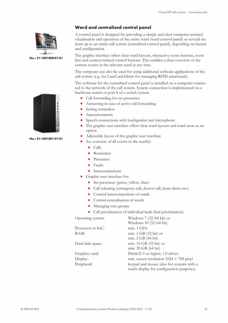
Ward and centralised control panel
No.: 21-1001000-01-01
No.: 21-1001001-01-01
A control panel is designed for providing a simple and clear computer-assistedvisualisation and operation of the entire ward (ward control panel) or several sta-tions up to an entire call system (centralised control panel), depending on licenceand configuration.The graphic interface offers clear ward layouts, interactive room buttons, eventlists and context-related control buttons. This enables a clear overview of thecurrent events in the relevant ward at any time.The computer can also be used for using additional software applications of thecall system (e.g. for CareCardAdmin for managing RFID smartcards).The software for the centralised control panel is installed on a computer connec-ted to the network of the call system. System connection is implemented via abackbone switch or port 8 of a switch system.
n Call forwarding for set presencesn Answering in case of active call forwardingn Setting remindersn Announcementsn Speech connections with loudspeaker and microphonen The graphic user interface offers clear ward layouts and ward areas as an
optionn Adjustable layout of the graphic user interfacen An overview of all events in the ward(s)
n Callsn Remindersn Presencesn Faultsn Interconnections
n Graphic user interface for:n Set presences (green, yellow, blue)n Call releasing (emergency call, doctor call, heart alarm etc.)n Control interconnections of wardsn Control centralisation of wardsn Managing care groupsn Call prioritisation of individual beds (bed prioritisation)
Operating system: Windows 7 (32/64 bit) orWindows 10 (32/64 bit)
Processor or SoC: min. 1 GHzRAM: min. 1 GB (32 bit) or
min. 2 GB (64 bit)Hard disk space: min. 16 GB (32 bit) or
min. 20 GB (64 bit)Graphics card: DirektX 9 or higher, 1.0 driverDisplay: min. screen resolution 1024 × 768 pixelPeripheral: keypad and mouse (also for systems with a
touch display for configuration purposes)

Visocall IP call systems · Answering units
22 Communications systems Product catalogue 2020/2021 · V 2.0 K-HB-0053EN
Network isolator EMOSAFE EN-70E
No.: 21-1000500-01
Coupling for the safe isolation (2 × MOPP according to DIN EN 60601-1) of acontrol panel or an external device from the rest of the call system (accordancewith VDE 0834).
n Safe isolation 2 × MOPP in accordance with DIN EN 60601-1n Can be used in PoE networks (no PoE power supply after the network
isolator)n Small size and easy installation
Required between:n System switch port 8 and control paneln System switch port 8 and external devicen Multimedia socket of a connection module (SM, SM-MMC) and external
deviceSystem compatibility: Visocall IPInterfaces/system connection: 2 × RJ-45 sockets for connection to a system
switch (port 8) or a backbone switchProtection class: IP 40Ambient temperature: -10 °C to +70 °CRelative air humidity: up to 90 % without condensationCase: Plastic, white/greyDimensions: 17.5 × 42 × 17 mm (H×W×D) without cable
base and receiverWeight: 12 g

Visocall IP call systems · Answering units
K-HB-0053EN Communications systems Product catalogue 2020/2021 · V 2.0 23
Answering units and accessories
Label Type Article no.
Staff terminal ST-TOUCH 21-1010500-01
Wall-mounted bracket for Staff Terminal ST-TOUCH-WH FC010003
Software licence telephone book functionfor Staff Terminal SWP-IP/PBF FC010064
Receiver for Staff Terminal (replacement)including connection cables ST-TOUCH-HK 21-1002050-01
Base for staff terminal (replacement) ST-TOUCH-STF 21-1002051-01
Connection cable for Staff Terminal Cable lengths 2.8 m ST-TOUCH-AK FC81818
Control panel PC touchHardware for operating a control panel, incl. operat-ing system, without control panel SW licence
LS-TOUCH 21-1001000-01
Control panel PCHardware for operating a control panel, incl. operat-ing system, without control panel SW licence
LS 21-1001001-01
Licence for the operation of a control panelSoftware licence ward control panel SWP-IP/SLS FC008050
Licence for the operation of a control panelSoftware licence ward control panel extension SWP-IP/SLS-E FC008052
Licence for the operation of a control panelSoftware licence centralised control panel SWP-IP/ZLS FC010053
Licence for the operation of a control panelSoftware licence centralised control panel extension SWP-IP/ZLS-E FC010054
Null modem cablewith two D-SUB DE9 connector plugs for the con-nection of two control panels via RS-232, cablelengths 2 m
DB9-2M 21-9031000-01
Null modem cablewith two D-SUB DE9 connector plugs for the con-nection of two control panels via RS-232, cablelengths 3 m
DB9-3M 21-9031001-01

Visocall IP call systems · Answering units
24 Communications systems Product catalogue 2020/2021 · V 2.0 K-HB-0053EN
Label Type Article no.
Network isolator EMOSAFE EMOSAFE EN-70E 21-1000500-01
VOIP receiverfor speech functions and announcements VOIP-H FC010071
Microphone USBfor Announcements and calls MIC-USB FC010074
Mifare Reader USBfor reading Mifare cards MFR-3700 FC017330
Mifare card MFC4C-CD 21-1002500-01

Visocall IP call systems · Patient handsets
K-HB-0053EN Communications systems Product catalogue 2020/2021 · V 2.0 25
3.3 Patient handsets· Patient handsets
Patient handsets are designed to release patient calls. They are designed as handy handheld devices for use frompatient beds. The devices can be changed any time by simply plugging them in and out. In accordance with VDE0834, this will generate a disconnection call in the system. All patient handsets are equipped with locating or reas-surance lights and are therefore suited for use in the dark.
CAUTIONDo not attach to rising aids
Devices and their cables may not be wound around or attached to rising aids, as the device may bedamaged if the patients use the device to pull themselves up. The devices may also be damage whenfalling off due to inappropriate mounting.
The relevant accessories must be used for attaching patient handsets to the bed.
Patient handsets can be broken down into two groups according to their range of functions:n Pear pushbuttons are very easy to use and enable patients to call care staff and control light sources
connected to the system.n Patient handsets are additionally equipped with a display and expendable functions including a speech
connection option between staff and Patient handsets.System connection is implemented as outlined via the relevant Intellifix socket of a connection module. This spe-cially designed plug and socket connection with auto disconnect mechanism minimises damage to cables, plugsand sockets. The PAT, PAT-E, PAT-L and BT-IP devices are connected to the blue Intellifix sockets. The pearpushbutton BT-B is connected to red Intellifix sockets.
Patient terminals Pearpushbutton
IP connection modules
IO-BUS connection modules
Basic connection modules
PAT PAT-E PAT-L BT-IP
BT-B
SM SM-MMC SM-S
SM-B SMU-B
SM1-B SM2-B SM1-B-S
Illustration 2: Connection scheme patient handsets

Visocall IP call systems · Patient handsets
26 Communications systems Product catalogue 2020/2021 · V 2.0 K-HB-0053EN
Product overview
Features PAT
PAT-
E
PAT-
L
BT-
IP
BT-
B
Call button (red) with locating and reassurance light • • • • •Room and reading light control (optional KNX) • • • • •Case and keypad in germ inhibiting design • • • • •Intellifix self-ejecting plugs • • • • •Call function with communication option • • •LC display with position alignment • • •Headphones socket • •Service call with speech option • •Radio operation • •Channel selection and volume control for system TV • •Integrated IP telephone • *Secocare Data • •Secocare Assist • •Control system for the blinds • •IR reception for integration of home automation devices • •Automatic volume level • •Menu-driven operation • •Numerical keypad •Connection to IP connection modules • • • •Connection to IO-BUS connection modules or basic connec-tion modules
•
* Limited to the acceptance of incoming telephone calls.

Visocall IP call systems · Patient handsets
K-HB-0053EN Communications systems Product catalogue 2020/2021 · V 2.0 27
Patient terminal PAT
No.: 21-1011000-01
No.: FC010240
No.: 21-1002005-01
Patient handset for call releasing, light, TV and blind control, playing radio pro-grammes and speech communication. The device is operated via a keypad andthe call button is equipped with a locating and reassurance light.System connection is implemented via an IP connection module with a blue In-tellifix socket. The relevant accessories must be used for attaching the device tothe bed.
n Call button in redundant execution with mechanical trigger and lightsensor
n Service call button, function optionally expendable with Secocare Assistn Holding device and antenna for reading RFID chip cardsn Care documentation via Secocare Datan Integrated loudspeaker and microphone for speech connectionsn Automatic volume adjustment when left to hangn Telephone functionn Radio function (requires sound interface)n Integrated headphones socketn Infrared receiver for environmental control devicesn Integrated LC display with position alignmentn Germ inhibiting membrane keypad for controlling two independent light
sources, electric blinds and a system TV.System compatibility: Visocall IPOperating voltage: 20 – 30 V DCPower consumption: 71 mA at 1,700 mW typ.Interfaces:
System connection: 1 × blue Intellifix plug for plugging into an IPconnection module (LAN interface with PoE)
RFID: RF communication in accordance with ISO/IEC 14443 Type A for MIFARE cards (Ultra-light, Classic, Plus and DESFire EV1)
Headphones socket: 3.5 mm jack plugInfrared receiver: 36 kHz receiver for RC5 signals
Display: Fully graphic LC display (128 × 64 pixels) withbacklight
Protection class: IP 54, VDE 0834 Environmental class IIIAmbient temperature: 0 °C to +40 °CRelative air humidity: up to 100 % without condensationCable: 2.8 m with 200 N strain relief (relating to the
device)Case: Plastic ASA, white RAL 9016Dimensions: 205 × 66 × 27 mm (H×W×D)Weight: 311 g

Visocall IP call systems · Patient handsets
28 Communications systems Product catalogue 2020/2021 · V 2.0 K-HB-0053EN
Patient terminal Easy PAT-E
No.: 21-1011002-01
No.: FC010240
No.: 21-1002005-01
Patient handset for call releasing, light, TV and blind control, playing radio pro-grammes and speech communication. The device is operated via a keypad andthe call button is equipped with a locating and reassurance light.System connection is implemented via an IP connection module with a blue In-tellifix socket. The relevant accessories must be used for attaching the device tothe bed.
n Two call buttons with mechanical triggern Service call button, function optionally expendable with Secocare Assistn Holding device and antenna for reading RFID chip cardsn Care documentation via Secocare Datan Integrated loudspeaker and microphone for speech connectionsn Automatic volume adjustment when left to hangn Telephone function for receiving telephone callsn Radio function (requires sound interface)n Integrated headphones socketn Infrared receiver for environmental control devicesn Integrated LC display with position alignmentn Germ inhibiting membrane keypad for controlling two independent light
sources, electric blinds and a system TV.System compatibility: Visocall IPOperating voltage: 20 – 30 V DCPower consumption: 71 mA at 1,700 mW typ.Interfaces:
System connection: 1 × blue Intellifix plug for plugging into an IPconnection module (LAN interface with PoE)
RFID: RF communication in accordance with ISO/IEC 14443 Type A for MIFARE cards (Ultra-light, Classic, Plus and DESFire EV1)
Headphones socket: 3.5 mm jack plugInfrared receiver: 36 kHz receiver for RC5 signals
Display: Fully graphic LC display (128 × 64 pixels) withbacklight
Protection class: IP 54, VDE 0834 Environmental class IIIAmbient temperature: 0 °C to +40 °CRelative air humidity: up to 100 % without condensationCable: 2.8 m with 200 N strain relief (relating to the
device)Case: Plastic ASA, white RAL 9016Dimensions: 205 × 66 × 27 mm (H×W×D)Weight: 311 g

Visocall IP call systems · Patient handsets
K-HB-0053EN Communications systems Product catalogue 2020/2021 · V 2.0 29
Patient terminal Light PAT-L
No.: 21-1011003-01
No.: FC010240
No.: 21-1002005-01
Patient handset for call releasing, light control and speech communication. Thedevice is operated via a keypad; the call buttons are equipped with a locating andreassurance light.System connection is implemented via an IP connection module with a blue In-tellifix socket. The relevant accessories must be used for attaching the device tothe bed.
n Two call buttons with mechanical triggern Integrated loudspeaker and microphone for speech connectionsn Integrated LC display with position alignmentn Germ inhibiting membrane keypad for controlling two independent light
sourcesSystem compatibility: Visocall IPOperating voltage: 20 – 30 V DCPower consumption: 71 mA at 1,700 mW typ.Interfaces/system connection: 1 × blue Intellifix plug for plugging into an IP
connection module (LAN interface with PoE)Display: Fully graphic LC display (128 × 64 pixels) with
backlightProtection class: IP 54, VDE 0834 Environmental class IIIAmbient temperature: 0 °C to +40 °CRelative air humidity: up to 100 % without condensationCable: 2.8 m with 200 N strain relief (relating to the
device)Case: Plastic ASA, white RAL 9016Dimensions: 205 × 66 × 27 mm (H×W×D)Weight: 311 g

Visocall IP call systems · Patient handsets
30 Communications systems Product catalogue 2020/2021 · V 2.0 K-HB-0053EN
Pear pushbutton BT-IP
No.: 21-1011004-01
No.: FC010240
No.: 21-1002005-01
Patient handset for call releasing and light control. The device is operated via akeypad; the call buttons are equipped with a locating and reassurance light.System connection is implemented via an IP connection module with a blue In-tellifix socket. The relevant accessories must be used for attaching the device tothe bed.
n Two call buttons with mechanical triggern Germ inhibiting membrane keypad for controlling two independent light
sourcesSystem compatibility: Visocall IPOperating voltage: 20 – 30 V DCPower consumption: 71 mA at 1,700 mW typ.Interfaces/system connection: 1 × blue Intellifix plug for plugging into an IP
connection module (LAN interface with PoE)Protection class: IP 54, VDE 0834 Environmental class IIIAmbient temperature: 0 °C to +40 °CRelative air humidity: up to 100 % without condensationCable: 2.8 m with 200 N strain relief (relating to the
device)Case: Plastic ASA, white RAL 9016Dimensions: 205 × 66 × 27 mm (H×W×D)Weight: 290 g

Visocall IP call systems · Patient handsets
K-HB-0053EN Communications systems Product catalogue 2020/2021 · V 2.0 31
Pear pushbutton BT-B
No.: FC010240
No.: 21-1031000-01
Patient handset for call releasing and light control. The device is operated via akeypad; the call buttons are equipped with a locating and reassurance light.System connection is implemented via an IO-BUS connection module or a basicconnection module with a red Intellifix socket. The relevant accessories must beused for attaching the device to the bed.
n Two call buttons with mechanical triggern Germ inhibiting membrane keypad for controlling two independent light
sourcesSystem compatibility: Visocall IPOperating voltage: 20 – 30 V DCPower consumption: 5.8 mA at 110.2 mW typ.Interfaces/system connection: 1 × red Intellifix plug for plugging into an IO-
BUS connection module (basic interface withpower supply)
Protection class: IP 54, VDE 0834 Environmental class IIIAmbient temperature: 0 °C to +40 °CRelative air humidity: up to 100 % without condensationCable: 2.8 m with 200 N strain relief (relating to the
device)Case: Plastic ASA, white RAL 9016Dimensions: 97 × 66 × 27 mm (H×W×D)Weight: 194 g

Visocall IP call systems · Patient handsets
32 Communications systems Product catalogue 2020/2021 · V 2.0 K-HB-0053EN
Cradle K-PAT
No.: FC010240
Cradle for the upright storage of a patient terminal or pear pushbutton. The in-tegrated magnet turns up the volume of the connected patient handset. Twocountersunk head screws (Ø 4 mm) are needed to attach the device. The alu-minium base for PAT cradles can be used for mounting the device on a standardrail.System compatibility: Visocall IPCase: Plastic ASA, white RAL 9016Dimensions: 67 × 70 × 32 mm (H×W×D)Weight: 22 g
Aluminium base K-PAT-AS
No.: 21-1002200-01
Mounting base for attaching a K-PAT cradle to a standard rail. The aluminiumbase plus the locking screw and two screw for attaching the cradle are suppliedas standard.System compatibility: Visocall IPCase: AluminiumDimensions: 59 × 35 × 26 mm (H×W×D) (without locking
screw)Weight: 122 g
Holding clip HB-PAT
No.: 21-1002005-01
Holding clip for attaching a patient terminal or a BT-IP pear pushbutton to theside rail of a bed. The flat end of the clip is slid into the recess on the rear of thepatient handset. The bent end of the holder is then attached to the bed.
NOTE
The HB-PAT holding clip is insert into the rear card slot on the pa-tient handset; this means that the RFID function cannot be used incombination with this accessory.
System compatibility: Visocall IPCase: Plastic ASA, white RAL 9016Dimensions: 85 × 60 × 48 mm (H×W×D)Weight: 26 g

Visocall IP call systems · Patient handsets
K-HB-0053EN Communications systems Product catalogue 2020/2021 · V 2.0 33
Patient handsets and accessories
Label Type Article no.
Patient terminalincl. 2.8 m connection cable PAT 21-1011000-01
Patient terminalincl. 5 m connection cable PAT-500 21-1011000-02
Patient terminalincl. 35 cm connection cable PAT-035 21-1011000-03
Patient terminalwith 106 cm connection cable and RJ-45 connectorplug
PAT-RJ45-106 21-1011000-04
Patient terminal Easyincl. 2.8 m connection cable PAT-E 21-1011002-01
Patient terminal Easyincl. 5 m connection cable PAT-E-500 21-1011002-02
Patient terminal Easywith 106 cm connection cable with RJ-45 connectorplug
PAT-E-RJ45-106 21-1011002-03
Patient terminal Lightincl. 2.8 m connection cable PAT-L 21-1011003-01
Patient terminal Lightincl. 5 m connection cable PAT-L-500 21-1011003-02
Pear pushbuttonincl. 2.8 m connection cable BT-IP 21-1011004-01
Pear pushbutton Basic BT-B 21-1031000-01
Cradle K-PAT K-PAT FC010240
Aluminium base for cradle K-PAT K-PAT-AS 21-1002200-01
GooseneckFor mounting a K-PAT cradle to a standard rail SH-GTS ZZL10737

Visocall IP call systems · Patient handsets
34 Communications systems Product catalogue 2020/2021 · V 2.0 K-HB-0053EN
Label Type Article no.
Holding clip for PATFor attaching a patient terminal or a BT-IP pearpushbutton to the side rail of a bed
HB-PAT 21-1002005-01
Holding clip for PATFor attaching a device cable to a cable HC-PAT 21-1002006-01
Mounting bracketFor attaching a device cable to a cable HKL VCP FC006209
Mounting clipFor attaching a device cable to a rising aid HL27-VC FC12803--A
Mounting clipFor attaching a device cable to a rising aid HL38-VC FC12803--B
Holding clipFor attaching a device cable to a bed sheet HC-VC FC12804
Holding clip for connection cableFor attaching several device cables to the bed frame HB-VC FC12805
Headphones with headbandCable lengths 2 m KH FC005205
Connection cables PAT blue (replacement)Cable lengths 2.8 m AK-PAT-BL-280 EI931506-C
Connection cables PAT blue (replacement)Cable lengths 5 m AK-PAT-BL-500 EI931606-C500
Connection cables PAT blue (replacement)Cable lengths 35 cm AK-PAT-BL-35 EI931506-C035
Connection cables PAT blue (replacement)Cable lengths 50 cm AK-PAT-BL-50 EI931506-C050
Connection cables BT-B red (replacement)Cable lengths 2.8 m AK-BT-B EI931573-A
Connection cables BT-B red (replacement)Cable lengths 35 cm AK-BT-B EI931573-A035
Connection cables BT-B red (replacement)Cable lengths 50 cm AK-BT-B EI931573-A050
Connection cables BT-B red (replacement)Cable lengths 3.5 m AK5-BT-B EI931573-A350

Visocall IP call systems · Patient handsets
K-HB-0053EN Communications systems Product catalogue 2020/2021 · V 2.0 35
Label Type Article no.
Connection cables BT-B red (replacement)Cable lengths 5 m AK5-BT-B EI931573-A500
PAT spiral connection cable (replacement)with 33 cm connection cable and RJ-45 connectorplug
AK-PAT-BL-SPIRALE 21-1011250-01
Software licence Secocare data SWP-IP/CD FC010066
Software licence Secocare data extension SWP-IP/CD-E FC010067
Mifare card MFC4C-CD 21-1002500-01

Visocall IP call systems · Connection modules
36 Communications systems Product catalogue 2020/2021 · V 2.0 K-HB-0053EN
3.4 Connection modules· Connection modules
Connection modules with sockets act as the connecting piece between the hard-wired and exchangeable systemcomponents. This way, patient handsets, ward answering units, diagnostic devices, radio receivers, etc. can be con-nected or disconnected by the staff while the system is running.Individual connection modules offer features such as a multimedia socket, a call and cancel pushbutton or a basicinterface for connecting basic components including connection devices, pushbuttons or the light module LM-B.Connection modules can be broken down into two groups depending on their use:
n Connection modules are equipped with one or two Intellifix sockets for connecting patient handsets.The specially designed plug and socket connection with auto disconnect mechanism minimises damage tothe socket as well as to the connected connector plug and cable.
Some connection modules are equipped with a diagnostic socket for connection to additional instru-ments, diagnostic devices, for instance. Connection modules can be broken down according to their typeof system connection, i.e. in IP, IO-BUS and basic connection modules.
n Diagnostic modules are equipped with one to four diagnostic sockets for connecting instruments suchas diagnostic devices, contact mats, noise monitors, etc. to the system either via cable or a radio receiver.
System connection is implemented as outlined via an IP port, an IO-BUS or a basic interface, depending on theconnection module.
IP connection modules
IO-BUS connection modules
Diagnostic modules
Basic connection modules
System switch
Components with basic interface
SM SM-MMC SM-S
SMU-B SM-B
DM-IO
DM1-IP
DMU-IO
SMF-B
SM1-B SM2-B SM1-B-S
L4-SWI9-GBIT
ZTD-B ZTD-B-L ZT-B ZE-B
Illustration 3: Connection scheme connection modules

Visocall IP call systems · Connection modules
K-HB-0053EN Communications systems Product catalogue 2020/2021 · V 2.0 37
Product overview
Features SM SM-M
MC
SM-S
SM-B
SMU
-B
SM1-
B
SM2-
B
SM1-
B-S
DM
-IO
DM
U-IO
DM
1-IP
SMF-
B
Diagnostic socket, not powered • ••••Diagnostic socket, powered • • • • •••• •Socket, only for radio receivers •Fully compatible with radio receiver VR6-5 DIN-NT
• • • • • • • • •
Fully compatible with radio receiver VR6-5 • • • • • •Blue Intellifix socket for IP peripherals • • •Red Intellifix socket for BT-B • • • •• •Multimedia socket • •Call and acknowledgement button • •Connection to basic devices ••••Separate power supply • • •Connection to SWI9 IP port • • • •Connection to SWI9 IO-BUS • • • •Connection to basic interface • • • •

Visocall IP call systems · Connection modules
38 Communications systems Product catalogue 2020/2021 · V 2.0 K-HB-0053EN
Connection module SM
No.: 21-1011500-01
Connection module with powered diagnostic socket, blue Intellifix socket andmultimedia socket. Suitable for installation in the media duct or for wall mount-ing.For surface mounting, the corresponding APA-2 surface-mounted housing is re-quired; for countersunk mounting, a double connection box installed in the wallmust be provided for. Generally installed in patient rooms, near the bed in thevicinity of the headboard.
n Diagnostic socket for the optional connection of an Diagnostic device with safe isolation in accordance with DIN EN
60601-1 (2 × MOPP)n Diagnostic adapter for contact mats, noise monitors, etc.n Radio receiver VR6-5 DIN-NT (with power supply)n Radio receiver VR6-5 (without power supply)
n Blue Intellifix socket for the optional connection of an Patient terminalsn Pear pushbutton BT-IPn Staff terminals
n Front multimedia socket for network connections to a multimedia ter-minal; This must provide a safe isolation in accordance with DIN EN60601-1 (2 × MOPP).
n Automatic input monitoring of the diagnostic socket and the Intellifixsocket with automatic call releasing (disconnection call)
System compatibility: Visocall IPInterfaces:
System connection: 1 × RJ-45 socket for connection to the IP portof a SWI9 (LAN interface with PoE)
Diagnostic socket: 1 × 5-pin powered DIN socketBlue Intellifix socket: 1 × RJ-45 socket with release mechanism (LAN
interface with PoE)Multimedia socket: 1 × RJ-45 socket (only active when patient
handset is connected)Installation: Surface mounted, countersunk or in a service
ductProtection class: IP 32, VDE 0834 Environmental class IIAmbient temperature: +5 °C to +40 °CRelative air humidity: up to 95 % without condensationCase: Plastic ABS, white RAL 9016Dimensions: 83 × 160 × 43 mm (H×W×D)Weight: 105 g
Visocall IP call systems · Connection modules
K-HB-0053EN Communications systems Product catalogue 2020/2021 · V 2.0 39
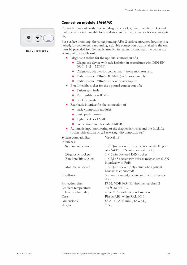
Connection module SM-MMC
No.: 21-1011501-01
Connection module with powered diagnostic socket, blue Intellifix socket andmultimedia socket. Suitable for installation in the media duct or for wall mount-ing.For surface mounting, the corresponding APA-2 surface-mounted housing is re-quired; for countersunk mounting, a double connection box installed in the wallmust be provided for. Generally installed in patient rooms, near the bed in thevicinity of the headboard.
n Diagnostic socket for the optional connection of an Diagnostic device with safe isolation in accordance with DIN EN
60601-1 (2 × MOPP)n Diagnostic adapter for contact mats, noise monitors, etc.n Radio receiver VR6-5 DIN-NT (with power supply)n Radio receiver VR6-5 (without power supply)
n Blue Intellifix socket for the optional connection of an Patient terminalsn Pear pushbutton BT-IPn Staff terminals
n Rear basic interface for the connection ofn basic connection modulesn basic pushbuttonsn Light modules LM-Bn connection modules radio SMF-B
n Automatic input monitoring of the diagnostic socket and the Intellifixsocket with automatic call releasing (disconnection call)
System compatibility: Visocall IPInterfaces:
System connection: 1 × RJ-45 socket for connection to the IP portof a SWI9 (LAN interface with PoE)
Diagnostic socket: 1 × 5-pin powered DIN socketBlue Intellifix socket: 1 × RJ-45 socket with release mechanism (LAN
interface with PoE)Multimedia socket: 1 × RJ-45 socket (only active when patient
handset is connected)Installation: Surface mounted, countersunk or in a service
ductProtection class: IP 32, VDE 0834 Environmental class IIAmbient temperature: +5 °C to +40 °CRelative air humidity: up to 95 % without condensationCase: Plastic ABS, white RAL 9016Dimensions: 83 × 160 × 43 mm (H×W×D)Weight: 105 g
Visocall IP call systems · Connection modules
40 Communications systems Product catalogue 2020/2021 · V 2.0 K-HB-0053EN
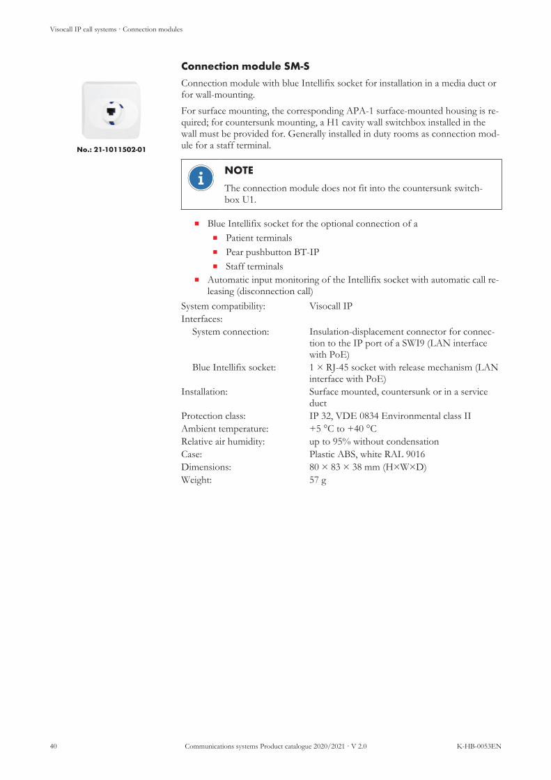
Connection module SM-S
No.: 21-1011502-01
Connection module with blue Intellifix socket for installation in a media duct orfor wall-mounting.For surface mounting, the corresponding APA-1 surface-mounted housing is re-quired; for countersunk mounting, a H1 cavity wall switchbox installed in thewall must be provided for. Generally installed in duty rooms as connection mod-ule for a staff terminal.
NOTE
The connection module does not fit into the countersunk switch-box U1.
n Blue Intellifix socket for the optional connection of an Patient terminalsn Pear pushbutton BT-IPn Staff terminals
n Automatic input monitoring of the Intellifix socket with automatic call re-leasing (disconnection call)
System compatibility: Visocall IPInterfaces:
System connection: Insulation-displacement connector for connec-tion to the IP port of a SWI9 (LAN interfacewith PoE)
Blue Intellifix socket: 1 × RJ-45 socket with release mechanism (LANinterface with PoE)
Installation: Surface mounted, countersunk or in a serviceduct
Protection class: IP 32, VDE 0834 Environmental class IIAmbient temperature: +5 °C to +40 °CRelative air humidity: up to 95% without condensationCase: Plastic ABS, white RAL 9016Dimensions: 80 × 83 × 38 mm (H×W×D)Weight: 57 g

Visocall IP call systems · Connection modules
K-HB-0053EN Communications systems Product catalogue 2020/2021 · V 2.0 41
Connection module SM-B
No.: 21-1021500-01
Connection module with diagnostic socket, red Intellifix socket, call and cancelbutton and four ports for basic components. Suitable for installation in the me-dia duct or for wall mounting.For surface mounting, the corresponding APA-2 surface-mounted housing is re-quired; for countersunk mounting, a double connection box installed in the wallmust be provided for. Generally installed in patient rooms, near the bed in thevicinity of the headboard.
n Diagnostic socket for the optional connection of an Diagnostic device with safe isolation in accordance with DIN EN
60601-1 (2 × MOPP)n Radio receiver VR6-5 DIN-NT (with power supply)
n Red Intellifix socket for connecting a BT-IP pear pushbuttonn Germ inhibiting membrane keypad with the following buttons:
n Answering button (green) with status LEDn Call button (red) with locating and reassurance light
n Rear basic interface for the connection ofn basic connection modulesn basic pushbuttonsn Light modules LM-Bn connection modules radio SMF-B
n Automatic input monitoring of the diagnostic socket and the Intellifixsocket with automatic call releasing (disconnection call)
System compatibility: Visocall IPInterfaces:
System connection: 2 × RJ-45 sockets for connection to the IOBUS of a SWI9 (RS485 interface with powersupply)
Diagnostic socket: 1 × 5-pin DIN socket without power supplyRed Intellifix socket: 1 × RJ-45 socket with release mechanism (basic
interface with power supply)Basic interface: 4 × RJ-12 sockets with power supply
Installation: Surface mounted, countersunk or in a serviceduct
Protection class: IP 32, VDE 0834 Environmental class IIAmbient temperature: +5 °C to +40 °CRelative air humidity: up to 95 % without condensationCase: Plastic ABS, white RAL 9016Dimensions: 83 × 160 × 43 mm (H×W×D)Weight: 124 g

Visocall IP call systems · Connection modules
42 Communications systems Product catalogue 2020/2021 · V 2.0 K-HB-0053EN
Connection module SMU-B
No.: 21-1021501-01
Connection module with powered diagnostic socket, red Intellifix socket and calland cancel button. Suitable for installation in the media duct or for wall mount-ing.For surface mounting, the corresponding APA-2 surface-mounted housing is re-quired; for countersunk mounting, a double connection box installed in the wallmust be provided for. Generally installed in patient rooms, near the bed in thevicinity of the headboard.
n Diagnostic socket for the optional connection of an Diagnostic device with safe isolation in accordance with DIN EN
60601-1 (2 × MOPP)n Diagnostic adapter for contact mats, noise monitors, etc.n Radio receiver VR6-5 DIN-NT (with power supply)n Radio receiver VR6-5 (without power supply)
n Red Intellifix socket for connecting a BT-IP pear pushbuttonn Germ inhibiting membrane keypad with the following buttons:
n Answering button (green) with status LEDn Call button (red) with locating and reassurance light
n Automatic input monitoring of the diagnostic socket and the Intellifixsocket with automatic call releasing (disconnection call)
System compatibility: Visocall IPInterfaces:
System connection: 2 × RJ-45 sockets for connection to the IOBUS of a SWI9 (RS-485 interface with powersupply)
24 V DC input: 1 × rear screw-type terminal for supplying thediagnostic socket with power
Diagnostic socket: 1 × 5-pin powered DIN socketRed Intellifix socket: 1 × RJ-45 socket with release mechanism (basic
interface with power supply)Installation: Surface mounted, countersunk or in a service
ductProtection class: IP 32, VDE 0834 Environmental class IIAmbient temperature: +5 °C to +40 °CRelative air humidity: up to 95 % without condensationCase: Plastic ABS, white RAL 9016Dimensions: 83 × 160 × 43 mm (H×W×D)Weight: 120 g

Visocall IP call systems · Connection modules
K-HB-0053EN Communications systems Product catalogue 2020/2021 · V 2.0 43
Connection module SM1-B
No.: 21-1031500-01
Connection module with powered diagnostic socket and red Intellifix socket.Suitable for installation in the media duct or for wall mounting.For surface mounting, the corresponding APA-2 surface-mounted housing is re-quired; for countersunk mounting, a double connection box installed in the wallmust be provided for. Generally installed in patient rooms, near the bed in thevicinity of the headboard.
n Diagnostic socket for the optional connection of an Diagnostic device with safe isolation in accordance with DIN EN
60601-1 (2 × MOPP)n Radio receiver VR6-5 DIN-NT (with power supply)
n Red Intellifix socket for connecting a BT-IP pear pushbuttonn Automatic input monitoring of the diagnostic socket and the Intellifix
socket with automatic call releasing (disconnection call)System compatibility: Visocall IPInterfaces:
System connection: 2 × RJ-12 sockets for connection to the basicinterface of a ZTD-B, ZTD-B-L, ZT-B, ZE-Bor SM-B
Diagnostic socket: 1 × 5-pin powered DIN socketRed Intellifix socket: 1 × RJ-45 socket with release mechanism (basic
interface with power supply)Installation: Surface mounted, countersunk or in a service
ductProtection class: IP 32, VDE 0834 Environmental class IIAmbient temperature: +5 °C to +40 °CRelative air humidity: up to 95 % without condensationCase: Plastic ABS, white RAL 9016Dimensions: 83 × 160 × 43 mm (H×W×D)Weight: 100 g

Visocall IP call systems · Connection modules
44 Communications systems Product catalogue 2020/2021 · V 2.0 K-HB-0053EN
Connection module SM2-B
No.: 21-1031502-01
Connection module with two red Intellifix sockets for installation in a mediaduct or for wall-mounting.For surface mounting, the corresponding APA-2 surface-mounted housing is re-quired; for countersunk mounting, a double connection box installed in the wallmust be provided for. Generally installed in patient rooms, near the bed in thevicinity of the headboard.
n Red Intellifix sockets for connecting two BT-IP pear pushbuttonsn Automatic input monitoring of the Intellifix socket with automatic call re-
leasing (disconnection call)System compatibility: Visocall IPInterfaces:
System connection: 2 × RJ-12 sockets for connection to the basicinterface of a ZTD-B, ZTD-B-L, ZT-B, ZE-Bor SM-B (with power supply)
Red Intellifix socket: 2 × RJ-45 sockets with release mechanism (basicinterface with power supply)
Installation: Surface mounted, countersunk or in a serviceduct
Protection class: IP 32, VDE 0834 Environmental class IIAmbient temperature: +5 °C to +40 °CRelative air humidity: up to 95 % without condensationCase: Plastic ABS, white RAL 9016Dimensions: 83 × 160 × 41 mm (H×W×D)Weight: 97 g

Visocall IP call systems · Connection modules
K-HB-0053EN Communications systems Product catalogue 2020/2021 · V 2.0 45
Connection module SM1-B-S
No.: 21-1031501-01
Connection module with red Intellifix socket for installation in a media duct orfor wall-mounting.For surface mounting, the corresponding APA-1 surface-mounted housing is re-quired; for countersunk mounting, a H1 cavity wall switchbox installed in thewall must be provided for. Generally installed in patient rooms, near the bed inthe vicinity of the headboard.
NOTE
The connection module does not fit into the countersunk switch-box U1.
n Red Intellifix socket for connecting a BT-IP pear pushbuttonn Automatic input monitoring of the Intellifix socket with automatic call re-
leasing (disconnection call)System compatibility: Visocall IPInterfaces:
System connection: 1 × RJ-12 socket for connection to the basic in-terface of a ZTD-B, ZTD-B-L, ZT-B, ZE-B orSM-B (with power supply)
Red Intellifix socket: 1 × RJ-45 socket with release mechanism (basicinterface with power supply)
Installation: Surface mounted, countersunk or in a serviceduct
Protection class: IP 32, VDE 0834 Environmental class IIAmbient temperature: +5 °C to +40 °CRelative air humidity: up to 95 % without condensationCase: Plastic ABS, white RAL 9016Dimensions: 80 × 83 × 42 mm (H×W×D)Weight: 52 g

Visocall IP call systems · Connection modules
46 Communications systems Product catalogue 2020/2021 · V 2.0 K-HB-0053EN
Diagnostic module DM-IO
No.: 21-1021800-01
Connection module with four diagnostic sockets for installation in a media ductor for wall-mounting.For surface mounting, the corresponding APA-2 surface-mounted housing is re-quired; for countersunk mounting, a double connection box installed in the wallmust be provided for. Generally installed in patient rooms, near the bed in thevicinity of the headboard.
n Diagnostic socket for the optional connection of an Diagnostic device with safe isolation in accordance with DIN EN
60601-1 (2 × MOPP)n Radio receiver VR6-5 DIN-NT (with power supply)
n Automatic input monitoring of the diagnostic socket with automatic callreleasing (disconnection call)
System compatibility: Visocall IPInterfaces:
System connection: 2 × RJ-45 sockets for connection to the IOBUS of a SWI9 (RS-485 interface with powersupply)
Diagnostic socket: 4 × 5-pin DIN sockets without power supplyInstallation: Surface mounted, countersunk or in a service
ductProtection class: IP 32, VDE 0834 Environmental class IIAmbient temperature: +5 °C to +40 °CRelative air humidity: up to 95 % without condensationCase: Plastic ABS, white RAL 9016Dimensions: 83 × 160 × 38 mm (H×W×D)Weight: 157 g

Visocall IP call systems · Connection modules
K-HB-0053EN Communications systems Product catalogue 2020/2021 · V 2.0 47
Diagnostic module DMU-IO
No.: 21-1021801-01
Connection module with four powered diagnostic sockets for installation in amedia duct or for wall-mounting.For surface mounting, the corresponding APA-2 surface-mounted housing is re-quired; for countersunk mounting, a double connection box installed in the wallmust be provided for. Generally installed in patient rooms, near the bed in thevicinity of the headboard.
n Diagnostic socket for the optional connection of an Diagnostic device with safe isolation in accordance with DIN EN
60601-1 (2 × MOPP)n Diagnostic adapter for contact mats, noise monitors, etc.n Radio receiver VR6-5 DIN-NT (with power supply)n Radio receiver VR6-5 (without power supply)
n Automatic input monitoring of the diagnostic socket with automatic callreleasing (disconnection call)
System compatibility: Visocall IPInterfaces:
System connection: 2 × RJ-45 sockets for connection to the IOBUS of a SWI9 (RS-485 interface with powersupply)
24 V DC input: 1 × rear screw-type terminal for supplying thediagnostic socket with power
Diagnostic socket: 4 × 5-pin powered DIN socketsInstallation: Surface mounted, countersunk or in a service
ductProtection class: IP 32, VDE 0834 Environmental class IIAmbient temperature: +5 °C to +40 °CRelative air humidity: up to 95 % without condensationCase: Plastic ABS, white RAL 9016Dimensions: 83 × 160 × 38 mm (H×W×D)Weight: 165 g

Visocall IP call systems · Connection modules
48 Communications systems Product catalogue 2020/2021 · V 2.0 K-HB-0053EN
Diagnostic module DM1-IP
No.: 21-1011800-01
Room-based connection module with powered diagnostic socket for installationin a media duct or for wall-mounting.For surface mounting, the corresponding APA-1 surface-mounted housing is re-quired; for countersunk mounting, a switchbox installed in the wall must beprovided for. Generally installed in patient rooms, near the bed in the vicinity ofthe headboard.
n Diagnostic socket for the optional connection of an Diagnostic device with safe isolation in accordance with DIN EN
60601-1 (2 × MOPP)n Diagnostic adapter for contact mats, noise monitors, etc.n Radio receiver VR6-5 DIN-NT (with power supply)n Radio receiver VR6-5 (without power supply)
n Automatic input monitoring of the diagnostic socket with automatic callreleasing (disconnection call)
System compatibility: Visocall IPInterfaces:
System connection: 1 × RJ-45 socket for connection to the IP portof a SWI9 (LAN interface with PoE)
Diagnostic socket: 1 × 5-pin powered DIN socketInstallation: Surface mounted, countersunk or in a service
ductProtection class: IP 32, VDE 0834 Environmental class IIAmbient temperature: +5 °C to +40 °CRelative air humidity: up to 95 % without condensationCase: Plastic ABS, white RAL 9016Dimensions: 80 × 83 × 36 mm (H×W×D)Weight: 69 g

Visocall IP call systems · Connection modules
K-HB-0053EN Communications systems Product catalogue 2020/2021 · V 2.0 49
Connection module radio components SMF-B
No.: 21-1031800-01
Connection module with powered socket for the connection of a radio receiver.Suitable for installation in the media duct or for wall mounting.For surface mounting, the corresponding APA-1 surface-mounted housing is re-quired; for countersunk mounting, a switchbox installed in the wall must beprovided for. Generally installed in patient rooms, near the bed in the vicinity ofthe headboard.
n Diagnostic socket for the optional connection of an Radio receiver VR6-5 DIN-NT (with power supply)n Radio receiver VR6-5 (without power supply)
n Automatic input monitoring of the diagnostic socket with automatic callreleasing (disconnection call)
System compatibility: Visocall IPInterfaces:
System connection: 1 × RJ-12 socket for connection to the basic in-terface of a ZTD-B, ZTD-B-L, ZT-B, ZE-B orSM-B
24 V DC input: 1 × rear screw-type terminal for supplying thediagnostic socket with power
Diagnostic socket: 1 × 5-pin powered DIN socketInstallation: Surface mounted, countersunk or in a service
ductProtection class: IP 32, VDE 0834 Environmental class IIAmbient temperature: +5 °C to +40 °CRelative air humidity: up to 95 % without condensationCase: Plastic ABS, white RAL 9016Dimensions: 80 × 83 × 29 mm (H×W×D)Weight: 73 g

Visocall IP call systems · Connection modules
50 Communications systems Product catalogue 2020/2021 · V 2.0 K-HB-0053EN
Diagnostic adapter AD-DIA
No.: 21-1002000-01
Accessories for the connection of a non-system, call-releasing device to a dia-gnostic socket. The diagnostic adapter provides for a galvanic isolation betweenthe connected device and the call system.
n Galvanic isolation between the connected device (contact mat, noise mon-itor, breathing sensor, etc.) and the call system
n Internal DIP switch for configuration of the call releasing in case of NOor NC contact
n Internal terminal resistance, removable, for circuit monitoring with ex-ternal 475 Ohm parallel to switching contact
n Diagnostic call when releasing the external devicen Automatic input monitoring of the diagnostic socket with automatic call
releasing (disconnection call)System compatibility: Visocall IPOperating voltage: 20 – 30 V DCPower consumption: 4 mA at 76 mW typ.Interfaces:
System connection: 1 × 5-pin DIN connector plug for the connec-tion of a live diagnostic socket of a SM, SM-MMC, SMU-B, SM1-B, DMU-IO or DM1-IP
Device connection: 1 × 2-wire cable with open ends for the connec-tion of a non-system device such as a contactmat, noise monitor, breathing sensor, etc.
Protection class: IP 32, VDE 0834 Environmental class IIAmbient temperature: +5 °C to +40 °CRelative air humidity: up to 95 % without condensationPlug sheath: Plastic, blackConnection cables: approx. 2.5 m with open cable endsCase: Plastic ABS, white RAL 9016Dimensions: 41 × 99 × 25 mm (H×W×D)Weight: 114 g

Visocall IP call systems · Connection modules
K-HB-0053EN Communications systems Product catalogue 2020/2021 · V 2.0 51
Diagnostic connection cable DSTK-W-VCIP
No.: FC010350
Accessories for the connection of a diagnostic device to a diagnostic socket. Thediagnostic device must provide a safe isolation in accordance with DIN EN60601-1 (2 × MOPP)
n Connecting a diagnostic device with safe isolation in accordance withDIN EN 60601-1 (2 × MOPP)
n With circuit diagram and resistance for circuit monitoringn Diagnostic call when releasing the external devicen Automatic input monitoring of the diagnostic socket with automatic call
releasing (disconnection call)System compatibility: Visocall IPInterfaces:
System connection: 1 × 5-pin DIN connector plug for the connec-tion of a live diagnostic socket of a SM, SM-MMC, SMU-B, SM1-B, DMU-IO or DM1-IP
Device connection: 1 × 2-wire cable with open ends for the connec-tion of a diagnostic device, providing for a safeisolation in accordance with DIN EN 60601-1(2 × MOPP)
Ambient temperature: up to +60 °CPlug sheath: metalCable mantle: PVC, whiteBranch Manager: 2 × 0.75 mm², fine-wire, flexibleCable length: approx. 2.5 mWeight: 123 g

Visocall IP call systems · Connection modules
52 Communications systems Product catalogue 2020/2021 · V 2.0 K-HB-0053EN
Connection modules and accessories
Label Type Article no.
Connection module SM SM 21-1011500-01
Connection module SM-MMC SM-MMC 21-1011501-01
Connection module single SM SM-S 21-1011502-01
Connection module SM-B SM-B 21-1021500-01
Connection module SMU-B SMU-B 21-1021501-01
Connection module SM1-B SM1-B 21-1031500-01
Connection module SM2-B SM2-B 21-1031502-01
Connection module SM1-B-S SM1-B-S 21-1031501-01
Diagnostic module DM-IO DM-IO 21-1021800-01
Diagnostic module DMU-IO DMU-IO 21-1021801-01
Diagnostic module DM1-IP DM1-IP 21-1011800-01
Connection module radio components SMF-B SMF-B 21-1031800-01
Blind cover, connection module, 10 pcs.For multimedia and diagnostic sockets, not suited forIntellifix sockets!
BLA-SM FC010295
Diagnostic adapter AD-DIA AD-DIA 21-1002000-01

Visocall IP call systems · Connection modules
K-HB-0053EN Communications systems Product catalogue 2020/2021 · V 2.0 53
Label Type Article no.
Diagnostic connection cable DSTK-W-VCIP FC010350
Countersunk double switchbox U2 FC88012
Cavity wall double switchbox H2 FC88013
AP case AP-2 APA-2 FC008992
Countersunk switchbox U1 FC88010
Cavity wall switchbox H1 21-2400000-01
AP case AP-1 APA-1 FC008991

Visocall IP call systems · Terminals
54 Communications systems Product catalogue 2020/2021 · V 2.0 K-HB-0053EN
3.5 Terminals· Terminals
Terminals are designed for use by the staff. They are installed in the entrance area of rooms so that presences canbe set when entering the room and deactivated when leaving the room. They are designed for releasing and can-celling calls and optionally also for the acoustic signalling of call forwarding.
n Communications terminals are equipped with presence buttons, a call button or optionally a doctorcall button, an integrated loudspeaker and a microphone for speech communication and a display.
n Room terminals are equipped with presence buttons, a call button or optionally a doctor call button aswell as a sound generator for the acoustic signalling in From of call forwarding. Depending on the model,the device may also be equipped with a display. Contrary to communications terminals, they provide forports for basic components, which however cannot be used for speech communication.
n RFID terminals enable a contactless presence management with the use of Mifare cards. Personalisedpresences make is possible to simultaneously set several presences of the same category in a room.
System connection is implemented as outlined via an IP port or IO-BUS, depending on the terminal.
System switch
Room terminals
Communications terminals
RFID terminals
KMT KMT-L
ZTD-B ZTD-B-L ZT-B
L4-SWI9-GBIT
RFID-IO-FRT RFID-IO
Illustration 4: Connection scheme terminals

Visocall IP call systems · Terminals
K-HB-0053EN Communications systems Product catalogue 2020/2021 · V 2.0 55
Product overview
Features KM
T
KM
T-L
ZTD
-B
ZTD
-B-L
ZT-
B
RFI
D-IO
-FR
T
RFI
D-IO
Green presence button • • • • •Blue presence button • • •Yellow presence button • •Presences via RFID card • •Call button • • • • • •Doctor call button • • •Configurable special call •Call forwarding • • • • • • •Call answering • •Setting reminders • •Announcements • •Display • • • •Timer function • •Radio operation • •Connection to basic devices ••••• ••••• •••••Connection to SWI9 IP port • •Connection to SWI9 IO-BUS • • • • •

Visocall IP call systems · Terminals
56 Communications systems Product catalogue 2020/2021 · V 2.0 K-HB-0053EN
Communications terminal KMT
No.: 21-1010000-01
Terminal with acoustic and optical call forwarding, display, call and the presencekey as speech communication.Generally installed (wall-mounting) in patient rooms and common rooms. Forsurface mounting, the corresponding AP-KMT surface-mounted frame is re-quired; for countersunk mounting of the case frames DR-KMT, a double con-nection box installed in the wall must be provided for.
n Call forwarding for set presencesn Call answering in case of active call forwardingn Setting reminders (with or without timer)n Announcementsn Timer functionn Radio function (requires sound interface)n Integrated loudspeaker and microphonen Integrated LC display with backlightn Germ inhibiting membrane keypad with the following buttons:
n Answering button (green) with status LEDn Answering button (blue) with status LEDn Answering button (yellow) with status LEDn Call button (red) with locating and reassurance lightn Doctor call button (blau) with reassurance lightn Answering button (grey) with status LEDn Three function buttons
n Rear socket for multimedia terminal with safe isolation (in accordancewith DIN EN 60601-1)
System compatibility: Visocall IPOperating voltage: 20 – 30 V DCPower consumption: 95.7 mA at 2,200 mW typ.Interfaces:
System connection: 1 × RJ-45 socket for connection to the IP portof a SWI9 (LAN interface with PoE)
Multimedia socket: 1 × RJ-45 socketDisplay: Fully graphic LC display (128 × 64 pixels) with
backlightInstallation: Surface or countersunk mountingProtection class: IP 32, VDE 0834 Environmental class IIAmbient temperature: +5 °C to +40 °CRelative air humidity: up to 95 % without condensationCase: Plastic ABS, white RAL 9016Dimensions: 205 × 87 × 24 mm (H×W×D)Weight: 210 g
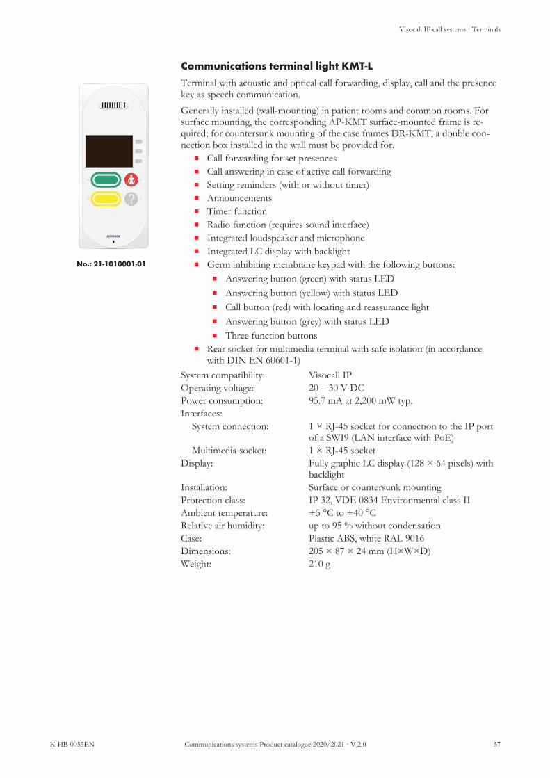
Visocall IP call systems · Terminals
K-HB-0053EN Communications systems Product catalogue 2020/2021 · V 2.0 57
Communications terminal light KMT-L
No.: 21-1010001-01
Terminal with acoustic and optical call forwarding, display, call and the presencekey as speech communication.Generally installed (wall-mounting) in patient rooms and common rooms. Forsurface mounting, the corresponding AP-KMT surface-mounted frame is re-quired; for countersunk mounting of the case frames DR-KMT, a double con-nection box installed in the wall must be provided for.
n Call forwarding for set presencesn Call answering in case of active call forwardingn Setting reminders (with or without timer)n Announcementsn Timer functionn Radio function (requires sound interface)n Integrated loudspeaker and microphonen Integrated LC display with backlightn Germ inhibiting membrane keypad with the following buttons:
n Answering button (green) with status LEDn Answering button (yellow) with status LEDn Call button (red) with locating and reassurance lightn Answering button (grey) with status LEDn Three function buttons
n Rear socket for multimedia terminal with safe isolation (in accordancewith DIN EN 60601-1)
System compatibility: Visocall IPOperating voltage: 20 – 30 V DCPower consumption: 95.7 mA at 2,200 mW typ.Interfaces:
System connection: 1 × RJ-45 socket for connection to the IP portof a SWI9 (LAN interface with PoE)
Multimedia socket: 1 × RJ-45 socketDisplay: Fully graphic LC display (128 × 64 pixels) with
backlightInstallation: Surface or countersunk mountingProtection class: IP 32, VDE 0834 Environmental class IIAmbient temperature: +5 °C to +40 °CRelative air humidity: up to 95 % without condensationCase: Plastic ABS, white RAL 9016Dimensions: 205 × 87 × 24 mm (H×W×D)Weight: 210 g

Visocall IP call systems · Terminals
58 Communications systems Product catalogue 2020/2021 · V 2.0 K-HB-0053EN
Room terminal with display ZTD-B
No.: 21-1020000-01
Terminal with acoustic and optical call forwarding, display, call and presence but-tons as well as five ports for basic components.Generally installed (wall-mounting) in patient rooms and common rooms. Forsurface mounting, the corresponding AP-KMT surface-mounted frame is re-quired; for countersunk mounting of the case frames DR-KMT, a double con-nection box installed in the wall must be provided for.
n Call forwarding for set presencesn Integrated sound generator for signalling in case of call forwardingn Integrated LC display with backlightn Germ inhibiting membrane keypad with the following buttons:
n Answering button (green) with status LEDn Answering button (blue) with status LEDn Call button (red) with locating and reassurance lightn Doctor call button (blau) with reassurance lightn Three function buttons
System compatibility: Visocall IPOperating voltage: 15 – 30 V DCPower consumption: 11.3 mA at 215 mW typ.Interfaces:
System connection: 2 × RJ-45 sockets for connection to the IOBUS of a SWI9 (RS-485 interface with powersupply)
Basic interface: 5 × RJ-12 sockets via which the basic compon-ents can be connected to the system
Display: Fully graphic LC display (128 × 64 pixels) withbacklight
Installation: Surface or countersunk mountingProtection class: IP 32, VDE 0834 Environmental class IIAmbient temperature: +5 °C to +40 °CRelative air humidity: up to 95 % without condensationCase: Plastic ABS, white RAL 9016Dimensions: 205 × 87 × 25 mm (H×W×D)Weight: 171 g

Visocall IP call systems · Terminals
K-HB-0053EN Communications systems Product catalogue 2020/2021 · V 2.0 59
Room terminal with display light ZTD-B- L
No.: 21-1020001-01
Terminal with acoustic and optical call forwarding, display, call and presence but-tons as well as five ports for basic components.Generally installed (wall-mounting) in patient rooms and common rooms. Forsurface mounting, the corresponding AP-KMT surface-mounted frame is re-quired; for countersunk mounting of the case frames DR-KMT, a double con-nection box installed in the wall must be provided for.
n Call forwarding for set presencesn Integrated sound generator for signalling in case of call forwardingn Integrated LC display with backlightn Germ inhibiting membrane keypad with the following buttons:
n Answering button (green) with status LEDn Call button (red) with locating and reassurance lightn Three function buttons
System compatibility: Visocall IPOperating voltage: 15 – 30 V DCPower consumption: 11.3 mA at 215 mW typ.Interfaces:
System connection: 2 × RJ-45 sockets for connection to the IOBUS of a SWI9 (RS-485 interface with powersupply)
Basic interface: 5 × RJ-12 sockets via which the basic compon-ents can be connected to the system
Display: Fully graphic LC display (128 × 64 pixels) withbacklight
Installation: Surface or countersunk mountingProtection class: IP 32, VDE 0834 Environmental class IIAmbient temperature: +5 °C to +40 °CRelative air humidity: up to 95 % without condensationCase: Plastic ABS, white RAL 9016Dimensions: 205 × 87 × 25 mm (H×W×D)Weight: 171 g

Visocall IP call systems · Terminals
60 Communications systems Product catalogue 2020/2021 · V 2.0 K-HB-0053EN
Room terminal without display ZT-B
No.: 21-1020002-01
Terminal with acoustic call forwarding, call and presence buttons as well as fiveports for basic components.Generally installed (wall-mounting) in patient rooms and common rooms. Forsurface mounting, the corresponding AP-KMT surface-mounted frame is re-quired; for countersunk mounting of the case frames DR-KMT, a double con-nection box installed in the wall must be provided for.
n Call forwarding for set presencesn Integrated sound generator for signalling in case of call forwardingn Germ inhibiting membrane keypad with the following buttons:
n Answering button (green) with status LEDn Answering button (blue) with status LEDn Call button (red) with locating and reassurance lightn Doctor call button (blau) with reassurance light
System compatibility: Visocall IPOperating voltage: 15 – 30 V DCPower consumption: 11.3 mA at 215 mW typ.Interfaces:
System connection: 2 × RJ-45 sockets for connection to the IOBUS of a SWI9 (RS-485 interface with powersupply)
Basic interface: 5 × RJ-12 sockets via which the basic compon-ents can be connected to the system
Installation: Surface or countersunk mountingProtection class: IP 32, VDE 0834 Environmental class IIAmbient temperature: +5 °C to +40 °CRelative air humidity: up to 95 % without condensationCase: Plastic ABS, white RAL 9016Dimensions: 205 × 87 × 25 mm (H×W×D)Weight: 155 g

Visocall IP call systems · Terminals
K-HB-0053EN Communications systems Product catalogue 2020/2021 · V 2.0 61
RFID terminal RFID-IO-FRT
No.: 21-1020301-01
Terminal with acoustic call forwarding, one call and function button and a RFIDantenna for the contactless setting and deactivating of presences. The use of per-sonalised Mifare cards enables the simultaneous setting of several presences ofthe same staff category.Generally installed (wall-mounting) in patient rooms and common rooms. Forsurface mounting, the corresponding surface-mounted frame RFID-GH-APR isrequired; for countersunk mounting of the case frame RFID-GH-APR and aswitch-box installed in the wall must be provided for.
n Call forwarding for set presencesn Integrated sound generator for signalling in case of call forwarding or as a
response to reading processesn LED as acknowledgement during reading processesn Integrated antenna for reading RFID smartcardsn Three status LEDs for indicating set presences (green/blue/yellow)n Releasing of a stored special call by combined use of the RFID smartcard
and call buttonn Germ inhibiting membrane keypad with the following buttons:
n Grey function button, configurable for resetting presencesn Call button (red) with locating and reassurance light
System compatibility: Visocall IPOperating voltage: 15 – 30 V DCPower consumption: 7 mA at 160 mW typ.Interfaces:
System connection: 2 × RJ-45 sockets for connection to the IOBUS of a SWI9 (RS-485 interface with powersupply)
RFID aerial: RF communication in accordance with ISP/IEC14443 Type A for MIFARE cards (Ultralight,Classic, Plus and DESFire EV1)
Installation: Surface or countersunk mountingProtection class: IP 32, VDE 0834 Environmental class IIAmbient temperature: +5 °C to +40 °CRelative air humidity: up to 95 % without condensationCase: Plastic ABS, white RAL 9016Dimensions: 119 × 87 × 25 mm (H×W×D)Weight: 85 g

Visocall IP call systems · Terminals
62 Communications systems Product catalogue 2020/2021 · V 2.0 K-HB-0053EN
RFID terminal RFID-IO
No.: 21-1020300-01
Terminal with acoustic call forwarding as well as RFID antenna for the contact-less setting and deactivating of presences. The use of personalised Mifare cardsenables the simultaneous setting of several presences of the same staff category.Generally installed (wall-mounting) in patient rooms and common rooms. Forsurface mounting, the corresponding surface-mounted frame RFID-GH-APR isrequired; for countersunk mounting of the case frame RFID-GH-APR and aswitch-box installed in the wall must be provided for.
n Call forwarding for set presencesn Integrated sound generator for signalling in case of call forwarding or as a
response to reading processesn LED as acknowledgement during reading processesn Integrated antenna for reading RFID smartcardsn Fungicidal membrane without buttons
System compatibility: Visocall IPOperating voltage: 15 – 30 V DCPower consumption: 7 mA at 160 mW typ.Interfaces:
System connection: 2 × RJ-45 sockets for connection to the IOBUS of a SWI9 (RS-485 interface with powersupply)
RFID aerial: RF communication in accordance with ISP/IEC14443 Type A for MIFARE cards (Ultralight,Classic, Plus and DESFire EV1)
Installation: Surface or countersunk mountingProtection class: IP 32, VDE 0834 Environmental class IIAmbient temperature: +5 °C to +40 °CRelative air humidity: up to 95 % without condensationCase: Plastic ABS, white RAL 9016Dimensions: 119 × 87 × 25 mm (H×W×D)Weight: 85 g

Visocall IP call systems · Terminals
K-HB-0053EN Communications systems Product catalogue 2020/2021 · V 2.0 63
Terminals and accessories
Label Type Article no.
Communications terminal KMT 21-1010000-01
Communications terminal Light KMT-L 21-1010001-01
Room terminal with display ZTD-B 21-1020000-01
Room terminal Light display ZTD-B-L 21-1020001-01
Room terminal without display ZT-B 21-1020002-01
Surface mounted frame AP-KMT FC010190
Case frame DR-KMT FC010191
Countersunk double switchbox U2 FC88012
Cavity wall double switchbox H2 FC88013
RFID terminal RFID-IO-FRT RFID-IO-FRT 21-1020301-01
RFID terminal RFID-IO RFID-IO 21-1020300-01
Mifare card MFC4C-CD 21-1002500-01
Installation frame for surface mounting RFID-GH-APR EI931617
Installation frame for countersunk mounting RFID-GH-UPR EI931618

Visocall IP call systems · Terminals
64 Communications systems Product catalogue 2020/2021 · V 2.0 K-HB-0053EN
Label Type Article no.
Countersunk switchbox U1 FC88010
Cavity wall switchbox H1 21-2400000-01

Visocall IP call systems · Intercom terminals
K-HB-0053EN Communications systems Product catalogue 2020/2021 · V 2.0 65
3.6 Intercom terminals· Intercom terminals
Intercom terminals are devices designed for establishing a speech connection simply by pressing a button. The in-tercom terminal ICT-IP is especially robust and is mounted permanently in a wall. By pressing the integrated but-ton, a call is released in the Visocall IP system. By call answering, a speech connection can be built up to the ter-minal. The device is suited as door intercom terminal in weatherproof outdoor areas.The system function door intercom terminal enables a staff terminal to be used as a intercom terminal in a similarway. The configuration does not require the installation of special hardware, but can be realised for any IP con-nection modules. Connected staff terminals display a special operating interface, which can be used to build up adirect speech connection to a predefined patient terminal. A monitor lock can be set up for the protection of thepatient. The visitor intercom terminal is especially suited for visitors of patients in quarantine.System connection is implemented as outlined, depending on the device, either directly to a system switch or anIP connection module.
Intercom terminals System switch
IP connection modules
Visitor intercom terminal
ICT-IP
ST-TOUCH
VCIP Application Kit
System function:Visitor intercom terminal
L4-SWI9-GBIT
SM SM-MMC SM-S
Illustration 5: Connection scheme intercom terminals
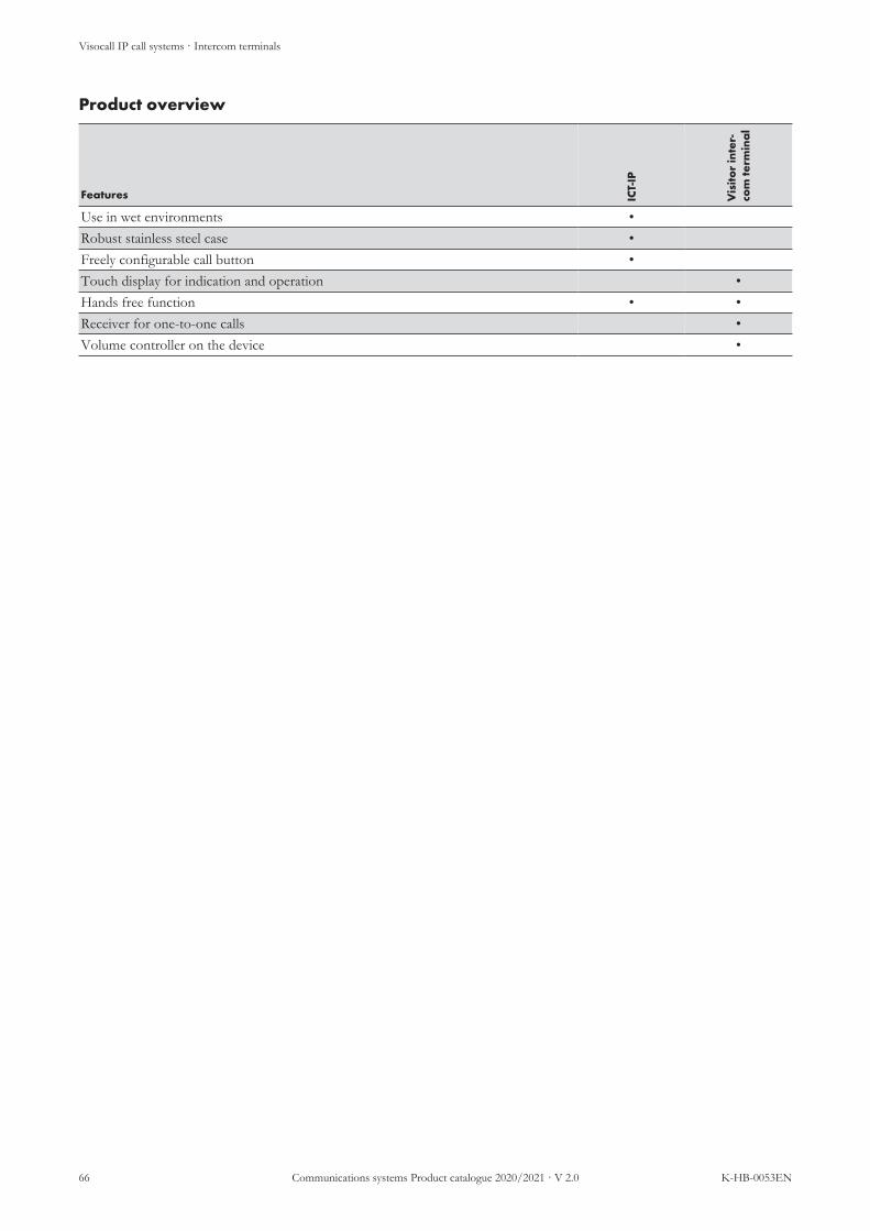
Visocall IP call systems · Intercom terminals
66 Communications systems Product catalogue 2020/2021 · V 2.0 K-HB-0053EN
Product overview
Features ICT-
IP
Vis
itor
inte
r-co
m te
rmin
al
Use in wet environments •Robust stainless steel case •Freely configurable call button •Touch display for indication and operation •Hands free function • •Receiver for one-to-one calls •Volume controller on the device •

Visocall IP call systems · Intercom terminals
K-HB-0053EN Communications systems Product catalogue 2020/2021 · V 2.0 67
Intercom Terminal ICT-IP
No.: 21-1010400-01
Especially robust IP terminal for releasing calls and speech communication.By pressing the integrated button, a predefined call is released. By call answering,a speech connection can be built up to the terminal. For door intercom termin-als, an input/output module can be used for opening doors.For countersunk mounting, a switch-box U-ICT-IP or H-ICT-IP installed in thewall must be provided for. Due to its moisture-proof circuit board and the ro-bust design, the device is typically used as door intercom terminal in weather-proof outdoor areas.
n For use in wet environmentsn Robust stainless steel casen Integrated loudspeaker and microphonen Stainless steel panel with freely configurable call button made of stainless
steel with locating and reassurance lightSystem compatibility: Visocall IPOperating voltage: 20 – 30 V DCPower consumption: 82.6 mA at 1,900 mW typ.Interfaces/system connection: 1 × RJ-45 socket for connection to the IP port
of a SWI9 (LAN interface with PoE)Installation: CountersunkProtection class: IP 42, VDE 0834 Environmental class IIAmbient temperature: -25 °C to +55 °CRelative air humidity: up to 95 %Case: Stainless steelDimensions: 120 × 120 × 32 mm (H×W×D)Weight: 446 g

Visocall IP call systems · Intercom terminals
68 Communications systems Product catalogue 2020/2021 · V 2.0 K-HB-0053EN
Visitor intercom terminal
No.: Upon request
The system function door intercom terminal”enables the use of a staff terminalfor direct communication with a predefined device (e.g. patient terminal). A vis-itor intercom terminal is especially suited for quarantine situations. Via the intuit-ive operating interface, visitors can build up a speech connection with a pre-defined patient without assistance by the staff. A monitor lock can be set up forthe protection of the patient.
NOTE
Supported from Application Kit 6

Visocall IP call systems · Intercom terminals
K-HB-0053EN Communications systems Product catalogue 2020/2021 · V 2.0 69
Intercom terminals and accessories
Label Type Article no.
Staff terminal ST-TOUCH 21-1010500-01
Visocall IP Application Kit SWP-IP/AK FC010040
Input/output module IO-M IO-M 21-1023000-01
Input/output module IO-M-P IO-M-P 21-1023001-01
Intercom terminal ICT-IP 21-1010400-01
Countersunk switchbox U-ICT-IP FC88019
Cavity wall switchbox H-ICT-IP FC88018

Visocall IP call systems · Pushbuttons
70 Communications systems Product catalogue 2020/2021 · V 2.0 K-HB-0053EN
3.7 Pushbuttons· Pushbuttons
Pushbuttons are devices which - depending on the version - are designed for setting and deactivating presences,releasing or cancelling calls. Models with integrated sound generators are also suited for the acoustic signalling callforwarding. Due to the standardised design of the cases, the outward appearance of the pushbutton models onlydiffers with regard to the front membrane keypad, the pull cord or a pneumatic element. The easy to clean, germinhibiting membrane keypad and the recessless design optimise the pushbuttons for use under circumstances withspecial hygiene requirements. Pushbuttons with call button, doctor call button or service call button are equippedwith a locating and reassurance light and therefore suited for use in the dark.Pushbutton models can be broken down into two groups depending on their connection options:
n IO-BUS pushbuttons are connected to the IO-BUS of a system switch. Some of these pushbuttons arealso available as a basic version.
n Basic pushbuttons are connect to a basic interface and look identical to the corresponding IO-BUS but-ton.
System connection is implemented as outlined via an IO-BUS or a basic interface.
IO-BUS PUSHBUTTONS System switch
Components with basic interface
Basic pushbuttons
RTB-IO SRT-IO ART-IO AT-IO
AWT-IO RAT-P-IO RATB-IO ARAT-P-IO
ZTB-IO ZRAT-IO PT-IO
RTB-B ART-B AT-B
RATB-B
ZRTB-B ZRAT-B PT-B
L4-SWI9-GBIT
ZTD-B ZTD-B-L ZT-B ZE-B
SM-B
Illustration 6: Connection scheme pushbuttons

Visocall IP call systems · Pushbuttons
K-HB-0053EN Communications systems Product catalogue 2020/2021 · V 2.0 71
Product overview
Features RTB
-IO
RTB
-B
SRT-
IO
AR
T-IO
AR
T-B
AT-
IO
AT-
B
AW
T-IO
RA
T-P-
IO
RA
TB-IO
RA
TB-B
AR
AT-
P-IO
ZTB
-IO
ZR
TB-B
ZR
AT-
IO
ZR
AT-
B
PT-IO
PT-B
Green cancel or presence button • • • • • • • •Blue presence button •Yellow presence button •Call button • • • • • •Service call button •Doctor call button • • •Call forwarding • •Pull cord (function call button) • • • •Pneumatic bellows (call button function) • •Use in wet rooms • • • • • • • •Connection to SWI9 IO-BUS • • • • • • • • • • •Connection to basic interface • • • • • • •

Visocall IP call systems · Pushbuttons
72 Communications systems Product catalogue 2020/2021 · V 2.0 K-HB-0053EN
Call pushbutton RTB-IO
No.: 21-1022001-01
IO-BUS pushbuttons for releasing calls, equipped with a moisture-proof circuitboard with locating and reassurance light. A green presence or cancel button isrequired for cancelling calls.Suitable for installation in the media duct or for wall mounting. For surfacemounting, the corresponding APA-1 surface-mounted housing is required; forcountersunk mounting, a switchbox installed in the wall must be provided for.Generally installed in patient rooms, common rooms and rooms with sanitary fa-cilities.
n Intended for use in wet roomsn Germ inhibiting membrane keypad with the following buttons:
n Call button (red) with locating and reassurance lightn Service call button (grey) with locating and reassurance light
System compatibility: Visocall IPOperating voltage: 15 – 30 V DCPower consumption: 2.7 mA at 51.3 mW typ.Interfaces/system connection: 2 × RJ-45 sockets for connection to the IO
BUS of a SWI9 (RS-485 interface with powersupply)
Installation: Surface mounted, countersunk or in a serviceduct
Protection class: IP 44, VDE 0834 Environmental class IIAmbient temperature: -25 °C to +55 °CRelative air humidity: up to 95 % without condensationCase: Plastic ABS, white RAL 9016Dimensions: 80 × 82 × 32 mm (H×W×D)Weight: 58 g

Visocall IP call systems · Pushbuttons
K-HB-0053EN Communications systems Product catalogue 2020/2021 · V 2.0 73
Call pushbutton RTB-B
No.: 21-1032000-01
Basic BUS pushbuttons for releasing calls, equipped with a moisture-proof cir-cuit board with locating and reassurance light.Suitable for installation in the media duct or for wall mounting. For surfacemounting, the corresponding APA-1 surface-mounted housing is required; forcountersunk mounting, a switchbox installed in the wall must be provided for.Generally installed in patient rooms, common rooms and rooms with sanitary fa-cilities.
n Intended for use in wet roomsn Germ inhibiting membrane keypad with the following buttons:
n Call button (red) with locating and reassurance lightSystem compatibility: Visocall IPOperating voltage: 15 – 30 V DCPower consumption: 5.8 mA at 110.2 mW typ.Interfaces/system connection: 1 × RJ-12 socket for connection to the basic in-
terface of a ZTD-B, ZTD-B-L, ZT-B, ZE-B orSM-B (basic interface with power supply)
Installation: Surface mounted, countersunk or in a serviceduct
Protection class: IP 44, VDE 0834 Environmental class IIAmbient temperature: 0 °C to +40 °CRelative air humidity: 5 to 100%Case: Plastic ABS, white RAL 9016Dimensions: 80 × 82 × 28 mm (H×W×D)Weight: 51 g

Visocall IP call systems · Pushbuttons
74 Communications systems Product catalogue 2020/2021 · V 2.0 K-HB-0053EN
Call and service pushbutton SRT-IO
No.: 21-1022018-01
IO-BUS pushbuttons for triggering calls and service calls, equipped with twolocating and reassurance lights. A green presence or cancel button is required forcancelling calls. For cancelling service calls, a yellow presence button or - whereconfigured - a green presence or cancel button is provided.Suitable for installation in the media duct or for wall mounting. For surfacemounting, the corresponding APA-1 surface-mounted housing is required; forcountersunk mounting, a switchbox installed in the wall must be provided for.Generally installed in patient rooms and common rooms.
n Germ inhibiting membrane keypad with the following buttons:n Call button (red) with locating and reassurance lightn Service call button (grey) with locating and reassurance light
System compatibility: Visocall IPOperating voltage: 15 – 30 V DCPower consumption: 2.7 mA at 51.3 mW typ.Interfaces/system connection: 2 × RJ-45 sockets for connection to the IO
BUS of a SWI9 (RS-485 interface with powersupply)
Installation: Surface mounted, countersunk or in a serviceduct
Protection class: IP 44, VDE 0834 Environmental class IIAmbient temperature: -25 °C to +55 °CRelative air humidity: up to 95 % without condensationCase: Plastic ABS, white RAL 9016Dimensions: 80 × 82 × 32 mm (H×W×D)Weight: 58 g

Visocall IP call systems · Pushbuttons
K-HB-0053EN Communications systems Product catalogue 2020/2021 · V 2.0 75
Doctor call pushbutton ART-IO
No.: 21-1022016-01
IO-BUS pushbuttons for releasing doctor calls, equipped with locating and reas-surance light. A green presence or cancel button is required for cancelling calls.Suitable for installation in the media duct or for wall mounting. For surfacemounting, the corresponding APA-1 surface-mounted housing is required; forcountersunk mounting, a switchbox installed in the wall must be provided for.Generally installed in rooms for patients requiring intensive care (intensive careunit).
n Germ inhibiting membrane keypad with the following buttons:n Doctor call button (blue) with locating and reassurance light
System compatibility: Visocall IPOperating voltage: 15 – 30 V DCPower consumption: 2.1 mA at 39.9 mW typ.Interfaces/system connection: 2 × RJ-45 sockets for connection to the IO
BUS of a SWI9 (RS-485 interface with powersupply)
Installation: Surface mounted, countersunk or in a serviceduct
Protection class: IP 44, VDE 0834 Environmental class IIAmbient temperature: -25 °C to +55 °CRelative air humidity: up to 95 % without condensationCase: Plastic ABS, white RAL 9016Dimensions: 80 × 82 × 32 mm (H×W×D)Weight: 58 g

Visocall IP call systems · Pushbuttons
76 Communications systems Product catalogue 2020/2021 · V 2.0 K-HB-0053EN
Doctor call pushbutton ART-B
No.: 21-1032016-01
Basic pushbuttons for releasing doctor calls, equipped with locating and reassur-ance light. A green presence or cancel button is required for cancelling calls.Suitable for installation in the media duct or for wall mounting. For surfacemounting, the corresponding APA-1 surface-mounted housing is required; forcountersunk mounting, a switchbox installed in the wall must be provided for.Generally installed in rooms for patients requiring intensive care (intensive careunit).
n Germ inhibiting membrane keypad with the following buttons:n Doctor call button (blue) with locating and reassurance light
System compatibility: Visocall IPOperating voltage: 15 – 30 V DCPower consumption: 5.8 mA at 110.2 mW typ.Interfaces/system connection: 1 × RJ-12 socket for connection to the basic in-
terface of a ZTD-B, ZTD-B-L, ZT-B, ZE-B orSM-B (basic interface with power supply)
Installation: Surface mounted, countersunk or in a serviceduct
Protection class: IP 44, VDE 0834 Environmental class IIAmbient temperature: -25 °C to +55 °CRelative air humidity: up to 95 % without condensationCase: Plastic ABS, white RAL 9016Dimensions: 80 × 82 × 28 mm (H×W×D)Weight: 51 g

Visocall IP call systems · Pushbuttons
K-HB-0053EN Communications systems Product catalogue 2020/2021 · V 2.0 77
Cancel pushbutton AT-IO
No.: 21-1022008-01
IO BUS pushbutton for cancelling calls and equipped with a status LED. Thecancel button can be optionally configured as a green presence button.Suitable for installation in the media duct or for wall mounting. For surfacemounting, the corresponding APA-1 surface-mounted housing is required; forcountersunk mounting, a switchbox installed in the wall must be provided for.Generally installed in wet rooms (toilets or wet groups).
n Germ inhibiting membrane keypad with the following buttons:n Answering button (green) with status LED
System compatibility: Visocall IPOperating voltage: 15 – 30 V DCPower consumption: 2.7 mA at 51.3 mW typ.Interfaces/system connection: 2 × RJ-45 sockets for connection to the IO
BUS of a SWI9 (RS-485 interface with powersupply)
Installation: Surface mounted, countersunk or in a serviceduct
Protection class: IP 44, VDE 0834 Environmental class IIAmbient temperature: -25 °C to +55 °CRelative air humidity: up to 95 % without condensationCase: Plastic ABS, white RAL 9016Dimensions: 80 × 82 × 32 mm (H×W×D)Weight: 58 g

Visocall IP call systems · Pushbuttons
78 Communications systems Product catalogue 2020/2021 · V 2.0 K-HB-0053EN
Cancel pushbutton AT-B
No.: 21-1032008-01
Basic pushbuttons for cancelling calls, equipped with a status LED. The cancelbutton can be optionally configured as a green presence button.Suitable for installation in the media duct or for wall mounting. For surfacemounting, the corresponding APA-1 surface-mounted housing is required; forcountersunk mounting, a switchbox installed in the wall must be provided for.Generally installed in wet rooms (toilets or wet groups).
n Germ inhibiting membrane keypad with the following buttons:n Answering button (green) with status LED
System compatibility: Visocall IPOperating voltage: 15 – 30 V DCPower consumption: 0 mA typ., max. 7 mAInterfaces/system connection: 1 × RJ-12 socket for connection to the basic in-
terface of a ZTD-B, ZTD-B-L, ZT-B, ZE-B orSM-B (basic interface with power supply)
Installation: Surface mounted, countersunk or in a serviceduct
Protection class: IP 44, VDE 0834 Environmental class IIAmbient temperature: -25 °C to +55 °CRelative air humidity: up to 95 % without condensationCase: Plastic ABS, white RAL 9016Dimensions: 80 × 82 × 28 mm (H×W×D)Weight: 51 g

Visocall IP call systems · Pushbuttons
K-HB-0053EN Communications systems Product catalogue 2020/2021 · V 2.0 79
Presence pushbutton AWT-IO
No.: 21-1022014-01
IO-BUS pushbuttons for setting and deactivating green and yellow presencesequipped with two status LED.Suitable for installation in the media duct or for wall mounting. For surfacemounting, the corresponding APA-1 surface-mounted housing is required; forcountersunk mounting, a switchbox installed in the wall must be provided for.Generally installed in rooms with two entrances, where a terminal is equipped.
n Germ inhibiting membrane keypad with the following buttons:n Answering button (green) with status LEDn Answering button (yellow) with status LED
System compatibility: Visocall IPOperating voltage: 15 – 30 V DCPower consumption: 2.7 mA at 51.3 mW typ.Interfaces/system connection: 2 × RJ-45 sockets for connection to the IO
BUS of a SWI9 (RS-485 interface with powersupply)
Installation: Surface mounted, countersunk or in a serviceduct
Protection class: IP 44, VDE 0834 Environmental class IIAmbient temperature: -25 °C to +55 °CRelative air humidity: up to 95 % without condensationCase: Plastic ABS, white RAL 9016Dimensions: 80 × 82 × 32 mm (H×W×D)Weight: 58 g

Visocall IP call systems · Pushbuttons
80 Communications systems Product catalogue 2020/2021 · V 2.0 K-HB-0053EN
Call/cancel pushbutton RAT-P-IO
No.: 21-1022012-01
IO-BUS pushbuttons with acoustic call forwarding for releasing calls and settingand deactivating green presences. Equipped with locating and reassurance lightand status LED.Suitable for installation in the media duct or for wall mounting. For surfacemounting, the corresponding APA-1 surface-mounted housing is required; forcountersunk mounting, a switchbox installed in the wall must be provided for.Generally installed in patient rooms.
n Call forwarding for set presencesn Integrated sound generator for signalling in case of call forwardingn Germ inhibiting membrane keypad with the following buttons:
n Answering button (green) with status LEDn Call button (red) with locating and reassurance light
System compatibility: Visocall IPOperating voltage: 15 – 30 V DCPower consumption: 2.7 mA at 51.3 mW typ.Interfaces/system connection: 2 × RJ-45 sockets for connection to the IO
BUS of a SWI9 (RS-485 interface with powersupply)
Installation: Surface mounted, countersunk or in a serviceduct
Protection class: IP 44, VDE 0834 Environmental class IIAmbient temperature: -25 °C to +55 °CRelative air humidity: up to 95 % without condensationCase: Plastic ABS, white RAL 9016Dimensions: 80 × 82 × 32 mm (H×W×D)Weight: 58 g

Visocall IP call systems · Pushbuttons
K-HB-0053EN Communications systems Product catalogue 2020/2021 · V 2.0 81
Call/cancel pushbutton RATB-IO
No.: 21-1022011-01
IO-BUS pushbuttons for releasing and cancelling calls, equipped with locatingand reassurance light and status LED. The cancel button can be optionally con-figured as a green presence button.Suitable for installation in the media duct or for wall mounting. For surfacemounting, the corresponding APA-1 surface-mounted housing is required; forcountersunk mounting, a switchbox installed in the wall must be provided for.Generally installed in patient rooms, common rooms and wet rooms (toilets andwet groups).
n Intended for use in wet roomsn Germ inhibiting membrane keypad with the following buttons:
n Answering button (green) with status LEDn Call button (red) with locating and reassurance light
System compatibility: Visocall IPOperating voltage: 15 – 30 V DCPower consumption: 2.7 mA at 51.3 mW typ.Interfaces/system connection: 2 × RJ-45 sockets for connection to the IO
BUS of a SWI9 (RS-485 interface with powersupply)
Installation: Surface mounted, countersunk or in a serviceduct
Protection class: IP 44, VDE 0834 Environmental class IIAmbient temperature: 0 °C to +40 °CRelative air humidity: 5 to 100%Case: Plastic ABS, white RAL 9016Dimensions: 80 × 82 × 32 mm (H×W×D)Weight: 58 g

Visocall IP call systems · Pushbuttons
82 Communications systems Product catalogue 2020/2021 · V 2.0 K-HB-0053EN
Call/cancel pushbutton RATB-B
No.: 21-1032011-01
IO-BUS pushbuttons for releasing and cancelling calls, equipped with locatingand reassurance light and status LED. The cancel button can be optionally con-figured as a green presence button.Suitable for installation in the media duct or for wall mounting. For surfacemounting, the corresponding APA-1 surface-mounted housing is required; forcountersunk mounting, a switchbox installed in the wall must be provided for.Generally installed in patient rooms, common rooms and wet rooms (toilets andwet groups).
n Intended for use in wet roomsn Germ inhibiting membrane keypad with the following buttons:
n Answering button (green) with status LEDn Call button (red) with locating and reassurance light
System compatibility: Visocall IPOperating voltage: 15 – 30 V DCPower consumption: 5.8 mA at 110.2 mW typ.Interfaces/system connection: 1 × RJ-12 socket for connection to the basic in-
terface of a ZTD-B, ZTD-B-L, ZT-B, ZE-B orSM-B (basic interface with power supply)
Installation: Surface mounted, countersunk or in a serviceduct
Protection class: IP 44, VDE 0834 Environmental class IIAmbient temperature: 0 °C to +40 °CRelative air humidity: 5 to 100%Case: Plastic ABS, white RAL 9016Dimensions: 80 × 82 × 28 mm (H×W×D)Weight: 51 g
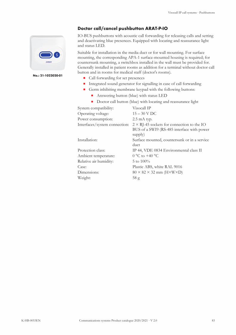
Visocall IP call systems · Pushbuttons
K-HB-0053EN Communications systems Product catalogue 2020/2021 · V 2.0 83
Doctor call/cancel pushbutton ARAT-P-IO
No.: 21-1022020-01
IO-BUS pushbuttons with acoustic call forwarding for releasing calls and settingand deactivating blue presences. Equipped with locating and reassurance lightand status LED.Suitable for installation in the media duct or for wall mounting. For surfacemounting, the corresponding APA-1 surface-mounted housing is required; forcountersunk mounting, a switchbox installed in the wall must be provided for.Generally installed in patient rooms as addition for a terminal without doctor callbutton and in rooms for medical staff (doctor's rooms).
n Call forwarding for set presencesn Integrated sound generator for signalling in case of call forwardingn Germ inhibiting membrane keypad with the following buttons:
n Answering button (blue) with status LEDn Doctor call button (blue) with locating and reassurance light
System compatibility: Visocall IPOperating voltage: 15 – 30 V DCPower consumption: 2.5 mA typ.Interfaces/system connection: 2 × RJ-45 sockets for connection to the IO
BUS of a SWI9 (RS-485 interface with powersupply)
Installation: Surface mounted, countersunk or in a serviceduct
Protection class: IP 44, VDE 0834 Environmental class IIAmbient temperature: 0 °C to +40 °CRelative air humidity: 5 to 100%Case: Plastic ABS, white RAL 9016Dimensions: 80 × 82 × 32 mm (H×W×D)Weight: 58 g

Visocall IP call systems · Pushbuttons
84 Communications systems Product catalogue 2020/2021 · V 2.0 K-HB-0053EN
Pull cord call switch ZTB-IO
No.: 21-1022003-01
IO-BUS pushbuttons for releasing calls with a pull cord, for individuals requiringassistance in situations with restricted mobility. Equipped with moisture-proofcircuit board and a locating and reassurance light. A green presence or cancelbutton is required for cancelling calls.Suitable for installation in the media duct or for wall mounting. For surfacemounting, the corresponding APA-1 surface-mounted housing is required; forcountersunk mounting, a switchbox installed in the wall must be provided for.Generally installed in wet rooms (toilets or wet groups).In accordance with VDE 0834, pull cord call switches must be installed inshower cabins at least 20 centimeter above the highest possible position of theshower head. The pull cord must end 10 to 20 centimerter above the floor.
n Intended for use in wet roomsn Integrated locating and reassurance lightn Actuating the pull cord has the same effect as pressing a call button (red)n Fast-exchange pull cord (approx. two meter) with snap hookn Red grip with nurse symbol
System compatibility: Visocall IPOperating voltage: 15 – 30 V DCPower consumption: 2.7 mA at 51.3 mW typ.Interfaces/system connection: 2 × RJ-45 sockets for connection to the IO
BUS of a SWI9 (RS-485 interface with powersupply)
Installation: Surface mounted, countersunk or in a serviceduct
Protection class: IP 44, VDE 0834 Environmental class IIAmbient temperature: -25 °C to +55 °CRelative air humidity: up to 95 %Case: Plastic ABS, white RAL 9016Pull cord: approx. 2 m, max. tensile force 120 NGrip: 30 × 35 × 13 mm (H×W×D)Dimensions: 80 × 82 × 53 mm (H×W×D)Weight: 59 g or 74 g (including pull cord and grip)

Visocall IP call systems · Pushbuttons
K-HB-0053EN Communications systems Product catalogue 2020/2021 · V 2.0 85
Pull cord call switch ZRTB-B
No.: 21-1032003-01
Basic pushbuttons for releasing calls with a pull cord, for individuals requiringassistance in situations with restricted mobility. Equipped with moisture-proofcircuit board and a locating and reassurance light. A green presence or cancelbutton is required for cancelling calls.Suitable for installation in the media duct or for wall mounting. For surfacemounting, the corresponding APA-1 surface-mounted housing is required; forcountersunk mounting, a switchbox installed in the wall must be provided for.Generally installed in wet rooms (toilets or wet groups).In accordance with VDE 0834, pull cord call switches must be installed inshower cabins at least 20 centimeter above the highest possible position of theshower head. The pull cord must end 10 to 20 centimerter above the floor.
n Intended for use in wet roomsn Integrated locating and reassurance lightn Actuating the pull cord has the same effect as pressing a call button (red)n Fast-exchange pull cord (approx. two meter) with snap hookn Red grip with nurse symbol
System compatibility: Visocall IPOperating voltage: 15 – 30 V DCPower consumption: 2.9 mA at 55.1 mW typ.Interfaces/system connection: 1 × RJ-12 socket for connection to the basic in-
terface of a ZTD-B, ZTD-B-L, ZT-B, ZE-B orSM-B (basic interface with power supply)
Installation: Surface mounted, countersunk or in a serviceduct
Protection class: IP 44, VDE 0834 Environmental class IIAmbient temperature: -25 °C to +55 °CRelative air humidity: up to 95 %Case: Plastic ABS, white RAL 9016Pull cord: approx. 2 m, max. tensile force 120 NGrip: 30 × 35 × 13 mm (H×W×D)Dimensions: 80 × 82 × 47 mm (H×W×D)Weight: 54 g or 69 g (including pull cord and grip)

Visocall IP call systems · Pushbuttons
86 Communications systems Product catalogue 2020/2021 · V 2.0 K-HB-0053EN
Pull cord call switch/cancel pushbutton ZRAT-IO
No.: 21-1022004-01
IO-BUS pushbuttons for releasing calls with a pull cord, for individuals requiringassistance in situations with restricted mobility. Equipped with moisture-proofcircuit board, cancel button and a locating and reassurance light status LED. Thecancel button can be optionally configured as a green presence button.Suitable for installation in the media duct or for wall mounting. For surfacemounting, the corresponding APA-1 surface-mounted housing is required; forcountersunk mounting, a switchbox installed in the wall must be provided for.Generally installed in wet rooms (toilets or wet groups).In accordance with VDE 0834, pull cord call switches must be installed inshower cabins at least 20 centimeter above the highest possible position of theshower head. The pull cord must end 10 to 20 centimerter above the floor.
n Intended for use in wet roomsn Integrated locating and reassurance lightn Actuating the pull cord has the same effect as pressing a call button (red)n Fast-exchange pull cord (approx. two meter) with snap hookn Red grip with nurse symboln Germ inhibiting membrane keypad with the following buttons:
n Answering button (green) with status LEDSystem compatibility: Visocall IPOperating voltage: 15 – 30 V DCPower consumption: 2.5 mA typ.Interfaces/system connection: 2 × RJ-45 sockets for connection to the IO
BUS of a SWI9 (RS-485 interface with powersupply)
Installation: Surface mounted, countersunk or in a serviceduct
Protection class: IP 44, VDE 0834 Environmental class IIAmbient temperature: -25 °C to +55 °CRelative air humidity: up to 95 %Case: Plastic ABS, white RAL 9016Pull cord: approx. 2 m, max. tensile force 120 NGrip: 30 × 35 × 13 mm (H×W×D)Dimensions: 80 × 82 × 53 mm (H×W×D)Weight: 59 g or 74 g (including pull cord and grip)

Visocall IP call systems · Pushbuttons
K-HB-0053EN Communications systems Product catalogue 2020/2021 · V 2.0 87
Pull cord call switch/cancel pushbutton ZRAT-B
No.: 21-1032004-01
Basic pushbuttons for releasing calls with a pull cord, for individuals requiringassistance in situations with restricted mobility. Equipped with moisture-proofcircuit board, cancel button and a locating and reassurance light status LED. Thecancel button can be optionally configured as a green presence button.Suitable for installation in the media duct or for wall mounting. For surfacemounting, the corresponding APA-1 surface-mounted housing is required; forcountersunk mounting, a switchbox installed in the wall must be provided for.Generally installed in wet rooms (toilets or wet groups).In accordance with VDE 0834, pull cord call switches must be installed inshower cabins at least 20 centimeter above the highest possible position of theshower head. The pull cord must end 10 to 20 centimerter above the floor.
n Intended for use in wet roomsn Integrated locating and reassurance lightn Actuating the pull cord has the same effect as pressing a call button (red)n Fast-exchange pull cord (approx. two meter) with snap hookn Red grip with nurse symboln Germ inhibiting membrane keypad with the following buttons:
n Answering button (green) with status LEDSystem compatibility: Visocall IPOperating voltage: 15 – 30 V DCPower consumption: 2.5 mA typ.Interfaces/system connection: 1 × RJ-12 socket for connection to the basic in-
terface of a ZTD-B, ZTD-B-L, ZT-B, ZE-B orSM-B (basic interface with power supply)
Installation: Surface mounted, countersunk or in a serviceduct
Protection class: IP 44, VDE 0834 Environmental class IIAmbient temperature: -25 °C to +55 °CRelative air humidity: up to 95 %Case: Plastic ABS, white RAL 9016Pull cord: approx. 2 m, max. tensile force 120 NGrip: 30 × 35 × 13 mm (H×W×D)Dimensions: 80 × 82 × 47 mm (H×W×D)Weight: 54 g or 69 g (including pull cord and grip)

Visocall IP call systems · Pushbuttons
88 Communications systems Product catalogue 2020/2021 · V 2.0 K-HB-0053EN
Pneumatic call switch PT-IO
No.: 21-1022006-01
IO-BUS pushbuttons for releasing calls with bellows, for individuals requiringassistance in situations with restricted mobility. Equipped with a locating and re-assurance light. A green presence or cancel button is required for cancelling calls.Suitable for installation in the media duct or for wall mounting. For surfacemounting, the corresponding APA-1 surface-mounted housing is required; forcountersunk mounting, a switchbox installed in the wall must be provided for.Generally installed in patient rooms near the bed in the bed in the vicinity of theheadboard and in facilities for peat pulp and mud baths.
n Integrated locating and reassurance lightn Actuating the bellows has the same effect as pressing a call button (red)n Fast-exchange plastic hose (approx. 2.2 m)
System compatibility: Visocall IPOperating voltage: 15 – 27 V DCPower consumption: 2.7 mA at 51.3 mW typ.Interfaces/system connection: 2 × RJ-45 sockets for connection to the IO
BUS of a SWI9 (RS-485 interface with powersupply)
Installation: Surface mounted, countersunk or in a serviceduct
Protection class: IP 44, VDE 0834 Environmental class IIAmbient temperature: -25 °C to +55 °CRelative air humidity: up to 95 % without condensationCase: Plastic ABS, white RAL 9016Plastic hose: approx. 2.2 mBellows: 79 × 61 mm (H×D)Dimensions: 80 × 82 × 52 mm (H×W×D)Weight: 54 g or 159 g (including hose and bellow)

Visocall IP call systems · Pushbuttons
K-HB-0053EN Communications systems Product catalogue 2020/2021 · V 2.0 89
Pneumatic call switch PT- B
No.: 21-1032006-01
Basic pushbuttons for releasing calls with bellows, for individuals requiring as-sistance in situations with restricted mobility. Equipped with a locating and reas-surance light. A green presence or cancel button is required for cancelling calls.Suitable for installation in the media duct or for wall mounting. For surfacemounting, the corresponding APA-1 surface-mounted housing is required; forcountersunk mounting, a switchbox installed in the wall must be provided for.Generally installed in patient rooms near the bed in the bed in the vicinity of theheadboard and in facilities for peat pulp and mud baths.
n Integrated locating and reassurance lightn Actuating the bellows has the same effect as pressing a call button (red)n Fast-exchange plastic hose (approx. 2.2 m)
System compatibility: Visocall IPOperating voltage: 15 – 30 V DCPower consumption: 2.9 mA at 55.1 mW typ.Interfaces/system connection: 1 × RJ-12 socket for connection to the basic in-
terface of a ZTD-B, ZTD-B-L, ZT-B, ZE-B orSM-B (basic interface with power supply)
Installation: Surface mounted, countersunk or in a serviceduct
Protection class: IP 44, VDE 0834 Environmental class IIAmbient temperature: -25 °C to +55 °CRelative air humidity: up to 95 % without condensationCase: Plastic ABS, white RAL 9016Plastic hose: approx. 2.2 mBellows: 79 × 61 mm (H×D)Dimensions: 80 × 82 × 44 mm (H×W×D)Weight: 49 g or 154 g (including hose and bellow)

Visocall IP call systems · Pushbuttons
90 Communications systems Product catalogue 2020/2021 · V 2.0 K-HB-0053EN
Pushbuttons and accessories
Label Type Article no.
Call pushbutton RTB-IO RTB-IO 21-1022001-01
Call pushbutton RTB-B RTB-B 21-1032000-01
Call and service pushbutton SRT-IO SRT-IO 21-1022018-01
Doctor call pushbutton ART-IO ART-IO 21-1022016-01
Doctor call pushbutton ART-B ART-B 21-1032016-01
Cancel pushbutton AT-IO AT-IO 21-1022008-01
Cancel pushbutton AT-B AT-B 21-1032008-01
Presence pushbutton AWT-IO AWT-IO 21-1022014-01
Call/cancel pushbutton RAT-P-IO RAT-P-IO 21-1022012-01
Call/cancel pushbutton RATB-IO RATB-IO 21-1022011-01
Call/cancel pushbutton RATB-B RATB-B 21-1032011-01
Doctor call/cancel pushbutton ARAT-P-IO ARAT-P-IO 21-1022020-01
Pull cord call switch ZTB-IO ZTB-IO 21-1022003-01
Pull cord call switch ZRTB-B ZRTB-B 21-1032003-01

Visocall IP call systems · Pushbuttons
K-HB-0053EN Communications systems Product catalogue 2020/2021 · V 2.0 91
Label Type Article no.
Pull cord call switch/cancel pushbutton ZRAT-IO ZRAT-IO 21-1022004-01
Pull cord call switch/cancel pushbutton ZRAT-B ZRAT-B 21-1032004-01
Pneumatic call switch PT-IO PT-IO 21-1022006-01
Pneumatic call switch PT- B PT-B 21-1032006-01
Pull cord call switch cord red incl. snap hookand grip, 10 pcs. (replacement)Pull cord length 2.3 m
ZT-S2-E 21-1002300-01
Pull cord call switch cord red incl. snap hookand grip, 10 pcs. (replacement)Pull cord length 4 m
ZT-S4-E 21-1002300-02
Pull cord call switch cord red incl. snap hook, 10pcs. (replacement)Pull cord length 2.3 m
ZT-S2 21-1002301-01
Pneumatic handheld button (replacement)with connection hose 2.2 m PT-BI EI931140
Pull cord call switch IP66with locating and reassurance light (change-over con-tact)
ZT-IP66 FC007972
Pull cord call switch IP68with locating light, without reassurance light (change-over contact)
ZT-IP68 FC007974
Call pushbutton IP66with locating light, without reassurance light (change-over contact)
RT-IP66 FC007975
Cancel pushbutton IP66with locating and reassurance light (change-over con-tact)
AT-IP66 FC007973
Countersunk switchbox U1 FC88010
Cavity wall switchbox H1 21-2400000-01
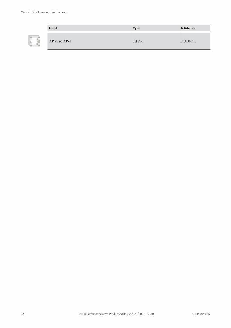
Visocall IP call systems · Pushbuttons
92 Communications systems Product catalogue 2020/2021 · V 2.0 K-HB-0053EN
Label Type Article no.
AP case AP-1 APA-1 FC008991

Visocall IP call systems · Call indications
K-HB-0053EN Communications systems Product catalogue 2020/2021 · V 2.0 93
3.8 Call indications· Call indications
Call indications are devices which are designed for the optical signalling of calls and reminders of all kinds. The in-formation is indicated in accordance with VDE 0834. VDE 0834 confirm call systems must additionally complywith the requirements with regard to the installation position.Call indications can be broken down into two groups:
n Overdoor lights are equipped with several indicator fields in different colours for indicating calls, pres-ences and reminders. The colour-coded indication is based on VDE 0834. Generally installed as a roomlamp in front of all rooms with a presence or call option.
n Large text indicators show calls and reminders in an alphanumeric order to guide staff to the call loca-tion by the shortest route. Generally installed in corridors, where they are used for the grouped indicationfor several rooms (analogous to group lamps).
System connection is implemented as outlined, depending on the model, via an IO-BUS, a basic interface or ahardware interface.
Signal lamps
Large text indicators
On-screen indicators
Text terminals
System switch
Components with basic interface
Hardware interfaces
LM-B LM-IO
ST-TOUCH
TXT
TXT-W
TXT-2W
TXT-D
TXT-2D
L4-SWI9-GBIT
ZTD-B ZTD-B-L ZT-B ZE-B
SM-B
VDVI-IP
VTXT-IP
Illustration 7: Connection scheme call indications

Visocall IP call systems · Call indications
94 Communications systems Product catalogue 2020/2021 · V 2.0 K-HB-0053EN
Product overview
Features LM-IO
LM-B
On-
scre
en in
-d
ica
tors
TXT
TXT-
W
TXT-
D
TXT-
2W
TXT-
2D
Use as room lamp • • •Use as group, care group and directionlamp
•
Colours for colour-coded indication ••••• •••• •••••Alphanumeric indication (wards androoms abbreviated)
• • • •• ••
Alphanumeric indication (wards androoms written out)
••
Loudspeaker for announcements • • • •• ••Separate power supply • •Connection to SWI9 IP port via VDVI-IP TVI-IP TVI-IP TVI-IP TVI-IP TVI-IPConnection to SWI9 IO-BUS •Connection to basic interface •

Visocall IP call systems · Call indications
K-HB-0053EN Communications systems Product catalogue 2020/2021 · V 2.0 95
Light module LM-IO
No.: 21-1022500-01
Call indication for the optical signalling of calls, presences and reminders. Fiveindicator fields for colour-coded indication in accordance with VDE 0834. Canbe used as room, group, care group and direction lamp.Suitable for wall mounting. For surface mounting, the corresponding APA-1 sur-face-mounted housing is required; for countersunk mounting, a switchbox in-stalled in the wall must be provided for. Generally installed as a room lamp infront of all rooms with a presence or call option.
n Discreet white light in idle moden Bright, eye-catching colours when activen Light-diffusing cover for even light signalsn Five LED indicator fields in the colours white, red, blue, yellow, green
with three colour LED eachSystem compatibility: Visocall IPOperating voltage: 15 – 27 V DCPower consumption: 60 mA at 1140 mW typ.Interfaces/system connection: 2 × RJ-45 sockets for connection to the IO
BUS of a SWI9 (RS-485 interface with powersupply)
Installation: Surface or countersunk mountingProtection class: IP 32, VDE 0834 Environmental class IIAmbient temperature: +5 °C to +40 °CRelative air humidity: up to 95 % without condensationLight sources:
Lighting intensity:Brightness:
max. 2500 Lux250 cd to 750 cd per m2 (depending on theviewing angle)
Case: Plastic ABS, white RAL 9010Light-diffusing cover: PMMA translucentDimensions: 80 × 82 × 60 mm (H×W×D)Weight: 101 g

Visocall IP call systems · Call indications
96 Communications systems Product catalogue 2020/2021 · V 2.0 K-HB-0053EN
Light module LM-B
No.: 21-1032500-01
Call indication usable as room lamp, for the optical signalling of calls, presencesand reminders. Four indicator fields for colour-coded indication in accordancewith VDE 0834. Suitable for wall mounting.Suitable for wall mounting. For surface mounting, the corresponding APA-1 sur-face-mounted housing is required; for countersunk mounting, a switchbox in-stalled in the wall must be provided for. Generally installed as a room lamp infront of all rooms with a presence or call option.
NOTE
The light module LM-B cannot be configured as a group, care groupor direction lamp.
n Discreet white light in idle moden Bright, eye-catching colours when activen Light-diffusing cover for even light signalsn Four LED indicator fields in the colours white, red, blue, green with three
colour LED eachSystem compatibility: Visocall IPOperating voltage: 15 – 307 V DCPower consumption: 60 mA at 1140 mW typ.Interfaces:
System connection: 1 × RJ-12 socket for connection to the basic in-terface of a ZTD-B, ZTD-B-L, ZT-B, ZE-B orSM-B (Basic interface)
24 VDC - input: Rear screw-type terminal for power supplyInstallation: Surface or countersunk mountingProtection class: IP 32, VDE 0834 Environmental class IIAmbient temperature: +5 °C to +40 °CRelative air humidity: up to 95 % without condensationLight sources:
Lighting intensity:Brightness:
max. 2500 Lux250 cd to 750 cd per m2 (depending on theviewing angle)
Case: Plastic ABS, white RAL 9010Light-diffusing cover: PMMA translucentDimensions: 80 × 82 × 54 mm (H×W×D)Weight: 99 g

Visocall IP call systems · Call indications
K-HB-0053EN Communications systems Product catalogue 2020/2021 · V 2.0 97
Text terminal TXT
No.: FC008810
No.: FC008811
No.: FC008812
No.: FC008814
Large text indicators for the grouped signalling of calls, presences and reminders.The alphanumeric indication of the call location guides the staff to the locationby the shortest route. Equipped with a loudspeaker. Available in differentdesigns for mounting on the ceiling or wall.For flush wall-mounting, the text terminal TXT and two wall wall-mountedbrackets TXT-WH are required. For wall-mounting at a right angle, the text ter-minal TXT-W - for ceiling mounting, the text terminals TXT-D and TXT-2D -can be used without additional accessories. Generally installed in corridors, com-munal areas and in front of staff duty rooms.
n Indication of calls and reminders of several rooms under consideration ofcall prioritiesn Alphanumeric indication of group/ward, room and bedn Indication of group/ward and room as abbreviations (three charac-
ters)n Alternating indication of time and date in idle moden Character height eight centimetern Up to twelve characters can be displayed simultaneouslyn 80 self-luminous LED per charactern Loudspeakers for the acoustic signalling of calls and for announcementsn Models with a display and loudspeaker:
n Text terminal TXT (flush wall-mounting)n Text terminal TXT-W (wall-mounting at a right angle)n Text terminal TXT-D (ceiling mounting)
n Models with two opposite displays and two loudspeakers:n Textterminal TXT-2D (ceiling mounting)
n The text terminals TXT-D and TXT-2D can be mounted at a distancebetween 82 cm and 100 cm from the ceiling
System compatibility: Visocall IP, Visocall PlusOperating voltage: 24 V DCPower consumption: approx. 50 mA typ. in idle mode
approx. 1 A when activatedInterfaces/system connection: Block terminal for the connection of a VTXT-
IP or V-TXT (RS-485 and RS-232 interface withpower supply and contacts for an analogue au-dio signal)
Installation: Surface mountingProtection class: VDE 0834 Environmental class ICase: Aluminium, white RAL 9010Dimensions: 978 × 110 × 40mm (H×W×D) each displayWeight:
TXTTXT-W, TXT-DTXT-2D
approx. 4 kgapprox. 4 kgapprox. 7.5 kg
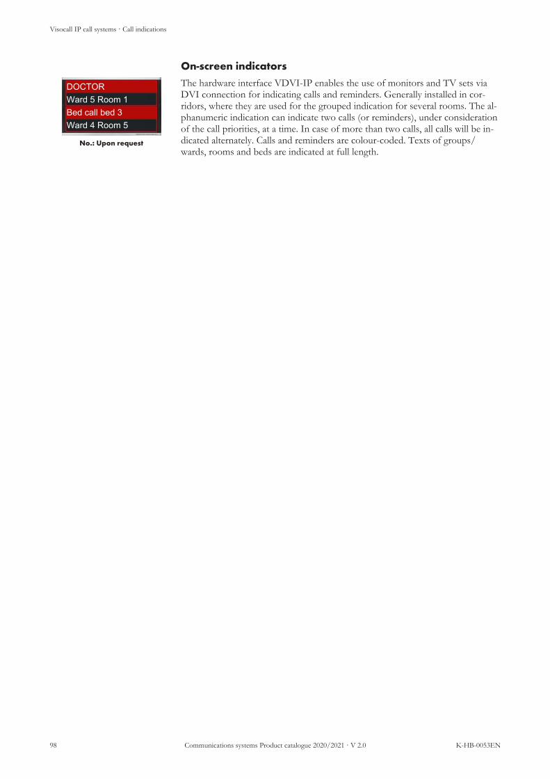
Visocall IP call systems · Call indications
98 Communications systems Product catalogue 2020/2021 · V 2.0 K-HB-0053EN
On-screen indicators
DOCTORWard 5 Room 1Bed call bed 3Ward 4 Room 5
No.: Upon request
The hardware interface VDVI-IP enables the use of monitors and TV sets viaDVI connection for indicating calls and reminders. Generally installed in cor-ridors, where they are used for the grouped indication for several rooms. The al-phanumeric indication can indicate two calls (or reminders), under considerationof the call priorities, at a time. In case of more than two calls, all calls will be in-dicated alternately. Calls and reminders are colour-coded. Texts of groups/wards, rooms and beds are indicated at full length.
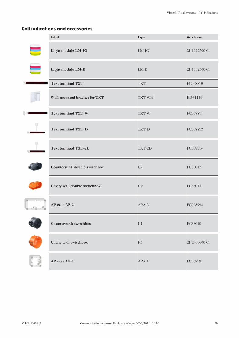
Visocall IP call systems · Call indications
K-HB-0053EN Communications systems Product catalogue 2020/2021 · V 2.0 99
Call indications and accessories
Label Type Article no.
Light module LM-IO LM-IO 21-1022500-01
Light module LM-B LM-B 21-1032500-01
Text terminal TXT TXT FC008810
Wall-mounted bracket for TXT TXT-WH EI931149
Text terminal TXT-W TXT-W FC008811
Text terminal TXT-D TXT-D FC008812
Text terminal TXT-2D TXT-2D FC008814
Countersunk double switchbox U2 FC88012
Cavity wall double switchbox H2 FC88013
AP case AP-2 APA-2 FC008992
Countersunk switchbox U1 FC88010
Cavity wall switchbox H1 21-2400000-01
AP case AP-1 APA-1 FC008991

Visocall IP call systems · Hardware interfaces
100 Communications systems Product catalogue 2020/2021 · V 2.0 K-HB-0053EN
3.9 Hardware interfaces· Hardware interfaces
Hardware interfaces are parts of the call system which serve as physical connection components for other systems.They enable audio systems, display devices, TV sets, light and blind controls, etc. to be integrated in the call sys-tem. The only exception are the room electronics ZE-B which serves as connection for basic devices.Hardware interfaces can be broken down into two groups depending on their connection options:
n IP interfaces are connected to the IP port of a system switch.n IO-BUS interfaces are connected to the IO-BUS of a system switch.
System connection is implemented as outlined via an IP port or IO-BUS, depending on the terminal.
IP interfaces System switch
IO-BUS interfaces
VDVI-IP TVI-IP
VTXT-IP MS4-I
IO-M SSR-IO
IO-M-P ZE-B
L4-SWI9-GBIT
Illustration 8: Connection scheme hardware interfaces

Visocall IP call systems · Hardware interfaces
K-HB-0053EN Communications systems Product catalogue 2020/2021 · V 2.0 101
Product overview
Features VD
VI-I
P
VTX
T-IP
TVI-I
P
MS4
-I
IO-M
-P
IO-M
SSR
-IO
ZE-
B
Sockets for on-screen indicators ••Sockets for text terminals ••Sockets for system TV •Connection for external audio systems (announcements) •Relay outputs controllable via the call system ••• •••Isolated inputs to the call system •••Non-isolated inputs to the call system •••Controllable electric circuits via the call system (light control) ••Connection to basic devices •••••Separate power supply •Connection to SWI9 IP port • • • •Connection to SWI9 IO-BUS • • • •

Visocall IP call systems · Hardware interfaces
102 Communications systems Product catalogue 2020/2021 · V 2.0 K-HB-0053EN
Connection distributor DVI monitor VDVI-IP
No.: 21-1013003-01
Hardware interface for the connection of one or two monitors for use as on-screen indicators (grouped indication of calls and reminders). The alphanumericindication of the call location guides the staff to the location by the shortestroute.Suitable for wall mounting. For surface mounting, the corresponding APA-2 sur-face-mounted housing is required; for countersunk mounting, a double connec-tion box installed in the wall must be provided for. Generally installed in cor-ridors, communal areas and in front of staff duty rooms.
n 2 DVI-D sockets for the connection of one monitor or TV eachn Output of the same image on both DVI socketsn Connection of HDMI devices via passive DVI-HDMI adapter pos-
siblen Image output with 1280 × 720 pixels and 60 Hz (720p60)n Indication of calls and reminders of several rooms under consideration of
call priorities; alphanumeric indication of group/ward, room and bedn Coloured display text with the following colour coding
n All calls are presented with a red backgroundn Heart alarms are presented with a light blue background and a red
framen Reminders are presented with the background colour of the relevant
staff category (green, blue, yellow)n Simultaneous indication of two calls (or reminders); In case of more than
two calls, all calls will be indicated alternatelyn Indication of time and date in idle mode (optionally also permanently; this
will enable only once call to be displayed at a time)n Optionally, information can be displayed during announcementsn Integrated sound generator for signalling in case of call forwarding
System compatibility: Visocall IPOperating voltage: 18.5 – 30 V DCPower consumption: 3,0 W typ. / max. 4,2 WInterfaces:
System connection: 1 × RJ-45 socket for connection to the IP portof a SWI9 (LAN interface with PoE)
Monitor/TV connection: 2 × DVI-D sockets for the connection of onemonitor or TV each (image output: 720p60)
Installation: Surface or countersunk mountingProtection class: IP 30, VDE 0834 Environmental class IAmbient temperature: 0 °C to +40 °CRelative air humidity: up to 95 % without condensationCase: Plastic ABS, white RAL 9016Dimensions: 83 × 160 × 34 mm (H×W×D)Weight: 158 g

Visocall IP call systems · Hardware interfaces
K-HB-0053EN Communications systems Product catalogue 2020/2021 · V 2.0 103
Connection distributor VTXT-IP
No.: 21-1013002-01
Hardware interface for the connection of one or two text terminals. Controls thetext and audio output of connect text terminalsSuitable for wall mounting. For surface mounting, the corresponding APA-2 sur-face-mounted housing is required; for countersunk mounting, a double connec-tion box installed in the wall must be provided for. Generally installed in cor-ridors, communal areas and in front of staff duty rooms.
n The following articles use a connection of the VTXT-IP:n Text terminal TXTn Text terminal TXT-Wn Text terminal TXT-D
n The following articles use both ports of the VTXT-IP:n Text terminal TXT-2D
System compatibility: Visocall IPOperating voltage: 20 – 30 V DCPower consumption: 69.6 mA at 1,600 mW typ.Interfaces:
System connection: 1 × RJ-45 socket for connection to the IP portof a SWI9 (LAN interface)
24 V DC input: 1 × screw-type terminal for supplying the con-nected text terminals sockets with power
Text terminal ports: 2 × block terminals for the connection of up totwo text terminals (RS-485 and RS-232 interfacewith power supply and contacts for an analogueaudio signal)
Installation: Surface or countersunk mountingProtection class: IP 32, VDE 0834 Environmental class IIAmbient temperature: +5 °C to +40 °CRelative air humidity: up to 95 % without condensationCase: Plastic ABS, white RAL 9016Dimensions: 83 × 160 × 34 mm (H×W×D)Weight: 155 g

Visocall IP call systems · Hardware interfaces
104 Communications systems Product catalogue 2020/2021 · V 2.0 K-HB-0053EN
TV interface TVI-IP
No.: 21-1013001-01
Hardware interface for the control of a connected system TV and for picking upits sound or feeding it into the Visocall IP system.Suitable for wall mounting. For surface mounting, the corresponding APA-2 sur-face-mounted housing is required; for countersunk mounting, a double connec-tion box installed in the wall must be provided for. Generally mounted in patientrooms and common rooms.
n Supports TV sets various manufacturersn TV set can be configured as a room TV or bed TVn Control of the TV via one or several patient terminalsn Audio output via the TV or the allocated patient terminals
System compatibility: Visocall IPOperating voltage: 20 – 30 V DCPower consumption: 82.6 mA at 1,900 mW typ.Interfaces:
System connection: 1 × RJ-45 socket for connection to the IP portof a SWI9 (LAN interface with PoE)
Connection TV set: 1 × 8-pin DIN socket for the connection of aTV set (TV control via RS-485, RS-232 orCMOS interface and conversion of the sound tothe call system)
Installation: Surface or countersunk mountingProtection class: IP 32, VDE 0834 Environmental class IIAmbient temperature: +5 °C to +40 °CRelative air humidity: up to 95 % without condensationCase: Plastic ABS, white RAL 9016Dimensions: 83 × 160 × 32 mm (H×W×D)Weight: 120 g

Visocall IP call systems · Hardware interfaces
K-HB-0053EN Communications systems Product catalogue 2020/2021 · V 2.0 105
Cable for TV Interface
No.: 21-1002031-01
No.: 21-1002031-02
No.: 21-1002031-03
No.: 21-1002031-04
No.: 21-1002031-05
No.: 21-1002030-01
No.: 21-1002030-02
Cable for connecting a system TV with a TV interface TVI-IP. Equipped withan 8-pin DIN connector plug for connection to the TV interface. Available inthe following version for connection to the TV set:
n Connection cable for Philips TVn 21-1002031-05: Y-cable emerging from DIN connector plug (straight)
to RJ-45 plug (straight, 1.5 m cable) and to 3.5 mm jack plug (angled,1.5 m cable)
n 21-1002031-02: Y-cable emerging from DIN connector plug (straight)to RJ-45 plug (straight, 1.5 m cable) and to 3.5 mm jack plug (straight,1.5 m cable)
n 21-1002031-03: Y-cable emerging from DIN connector plug (straight)to RJ-45 plug (straight, 3 m cable) and to 3.5 mm jack plug (straight, 3m cable)
n 21-1002031-04: Y-cable emerging from DIN connector plug (straight)to RJ-45 plug (straight, 4 m cable) and to 3.5 mm jack plug (straight, 4m cable)
n 21-1002031-01: Y-cable emerging from DIN connector plug (angled)to DIN plug (straight, 1.5 m cable) and to 3-pin connection strip (0.2m cable)
n Connection cable for Samsung TVn 21-1002030-01: Y-cable emerging from DIN connector plug (straight)
to RJ-12 plug (straight, 1.5 m cable) and to 3.5 mm jack plug (angled,1.5 m cable)
n 21-1002030-02: Y-cable emerging from DIN connector plug(straight) to RJ-45 plug (straight, 1.5 m cable) and to 3.5 mm jackplug (angled, 1.5 m cable)

Visocall IP call systems · Hardware interfaces
106 Communications systems Product catalogue 2020/2021 · V 2.0 K-HB-0053EN
Multi sound 4 interface MS4-I
No.: 21-1013000-01
Hardware interface for the connection of an external audio system. Dependingon the configuration, these can be fed into or picked up from the call systemwith MS4-I audio signals. Generally used for announcements.For surface mounting, the corresponding case GH-ZE-B and spacer ZUB-ZE-Bare required. For installation in a media duct, the board can be snapped off at theperforation. Generally installed in suspended ceilings and media ducts.
NOTE
The audio quality of the device does not correspond to any stand-ards for electroacoustics or evacuation systems.
n Plays announcements from an external source on the call systemn Plays announcements made in the call system on the external audio sys-
temn Plays the radio stream of a communications terminal on an external audio
systemn Input and output level adjustablen Multimedia socket for network connections to a multimedia terminal. This
must provide a safe isolation in accordance with DIN EN 60601-1 (2 ×MOPP).
System compatibility: Visocall IPOperating voltage: 16 – 30 V DCPower consumption: 140 mA typ. / max. 500 mAInterfaces:
System connection: 1 × RJ-45 socket for connection to the IP portof a SWI9 (LAN interface with PoE)
Multimedia socket: 1 × RJ-45 socketTerminal strip: 1 × screw-type terminal strip for audio output
and input (wire diameter up to 1.5 mm2)Audio output:
Level:Output impedance:
-20 to +6 dBV< 600 Ω> 1000 Ω
Audio input:Level:Input impedance:Recommended source im-pedance:
-38 to +10 dBV> 1000 Ω< 1000 Ω
Installation: Surface mounted or in a service ductProtection class: IP 32, VDE 0834 Environmental class IIAmbient temperature: +5 °C to +40 °CRelative air humidity: up to 95 % without condensationDimensions: 80 × 151 × 26 mm (H×W×D),
62 × 151 × 26 mm (H×W×D)(minimised)Weight: 102 g
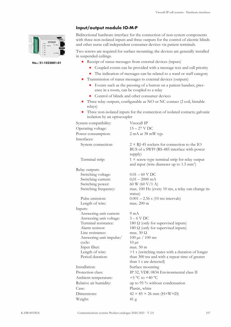
Visocall IP call systems · Hardware interfaces
K-HB-0053EN Communications systems Product catalogue 2020/2021 · V 2.0 107
Input/output module IO-M-P
No.: 21-1023001-01
Bidirectional hardware interface for the connection of non-system componentswith three non-isolated inputs and three outputs for the control of electric blindsand other nurse call independent consumer devices via patient terminals.Two screws are required for surface mounting; the devices are generally installedin suspended ceilings.
n Receipt of status messages from external devices (inputs)n Coupled events can be provided with a message text and call priorityn The indication of messages can be related to a ward or staff category
n Transmission of status messages to external devices (outputs)n Events such as the pressing of a button on a patient handset, pres-
ence in a room, can be coupled to a relayn Control of blinds and other consumer devices
n Three relay outputs, configurable as NO or NC contact (2 coil, bistablerelays)
n Three non-isolated inputs for the connection of isolated contacts; galvanicisolation by an optocoupler
System compatibility: Visocall IPOperating voltage: 15 – 27 V DCPower consumption: 2 mA at 38 mW typ.Interfaces:
System connection: 2 × RJ-45 sockets for connection to the IOBUS of a SWI9 (RS-485 interface with powersupply)
Terminal strip: 1 × screw-type terminal strip for relay outputand input (wire diameter up to 1.5 mm2)
Relay outputs:Switching voltage:Switching current:Switching power:Switching frequency:
Pulse emission:Length of wire:
0.01 – 60 V DC0,01 – 2000 mA60 W (60 V/1 A)max. 100 Hz (every 10 ms, a relay can change itsstatus)0.001 – 2.56 s (10 ms intervals)max. 200 m
Inputs:Answering unit current:Answering unit voltage:Terminal resistance:Alarm resistor:Line resistance:Answering unit impulse/cycle:Input filter:Length of wire:Period duration:
9 mA3 – 6 V DC180 Ω (only for supervised inputs)180 Ω (only for supervised inputs)max. 30 Ω100 µs / 100 ms10 µsmax. 50 m>1 s (switching states with a duration of longerthan 300 ms and with a repeat time of greaterthan 1 s are detected)
Installation: Surface mountingProtection class: IP 32, VDE 0834 Environmental class IIAmbient temperature: +5 °C to +40 °CRelative air humidity: up to 95 % without condensationCase: Plastic, whiteDimensions: 42 × 85 × 26 mm (H×W×D)Weight: 41 g

Visocall IP call systems · Hardware interfaces
108 Communications systems Product catalogue 2020/2021 · V 2.0 K-HB-0053EN
Input/output module IO-M
No.: 21-1023000-01
Bidirectional hardware interface for the connection of non-system componentswith three non-isolated inputs and three outputs for the control of electric blindsand other nurse call independent consumer devices via patient terminals.Two screws are required for surface mounting; the devices are generally installedin suspended ceilings.
n Receipt of status messages from external devices (inputs)n Coupled events can be provided with a message text and call priorityn The indication of messages can be related to a ward or staff category
n Transmission of status messages to external devices (outputs)n Events such as the pressing of a button on a patient handset, pres-
ence in a room, can be coupled to a relayn Control of blinds and other consumer devices
n Three relay outputs, configurable as NO or NC contact (2 coil, bistablerelays)
n Three non-isolated inputs for the connection of isolated contacts; galvanicisolation by an optocoupler
System compatibility: Visocall IPOperating voltage: 15 – 27 V DCPower consumption: 2 mA at 38 mW typ.Interfaces:
System connection: 2 × RJ-45 sockets for connection to the IOBUS of a SWI9 (RS-485 interface with powersupply)
Terminal strip: 1 × screw-type terminal strip for relay outputand input (wire diameter up to 1.5 mm2)
Relay outputs:Switching voltage:Switching current:Switching power:Switching frequency:
Pulse emission:Length of wire:
0.01 – 60 V DC0,01 – 2000 mA60 W (60 V/1 A)max. 100 Hz (every 10 ms, a relay can change itsstatus)0.001 – 2.56 s (10 ms intervals)max. 200 m
Inputs:Voltage range:Input resistance:Input current:Length of wire:
15 – 30 V DC4,990 Ωmax. 6 mAmax. 200 m
Installation: Surface mountingProtection class: IP 32, VDE 0834 Environmental class IIAmbient temperature: +5 °C to +40 °CRelative air humidity: up to 95 % without condensationCase: Plastic, whiteDimensions: 42 × 85 × 26 mm (H×W×D)Weight: 41 g

Visocall IP call systems · Hardware interfaces
K-HB-0053EN Communications systems Product catalogue 2020/2021 · V 2.0 109
Latching relay SSR-IO
No.: 21-1023004-01
Hardware interface for switching one or two separate circuits. An electric circuitcan be additionally controlled via a light switch. This is generally used for thecontrol of room and reading lights via patient handsets.Two screws are required for surface mounting; the devices are generally installedin suspended ceilings.
CAUTIONInadequate ventilation
At least 2 centimert space must be left around the ventilation slits.
n Switching of up to two separate electric circuits (e.g. room and readinglight)
n Control takes place via the call system (e.g. via patient handsets)n Output 1 can be additionally controlled via a commercial light switch
(function provided also without call system)n Power supply via 230 VAC input (L); if none is available, the power sup-
ply will be provided via the IO-BUSn Circuit diagram printed on the case
System compatibility: Visocall IPOperating voltage: primary 230 V AC +10 %/–15 % above input
(L), alternatively 10 – 30 V DC above IO-BUSPower consumption: 0.9 mA at 17.1 mW typ.Interfaces:
System connection: 2 × RJ-45 sockets for connection to the IOBUS of a SWI9 (RS-485 interface with powersupply)
Terminal strip: 1 × plug-in terminal strip for relay output andinput (wire diameter up to 1.5 mm2)
Relay outputs:Switching voltage:Constant current consump-tion:Inrush current surge for thedevice:Switching capacity uponopening:
max. 260 V ACmax. 8 Amax. 165 A/20 ms or 800 A/200 usmax. 4000 VA
Pushbutton input (SW):Input voltage:Input current:
230 V AC + 10 %/– 15 %6 mA typ.
Installation: Surface mountingProtection class: IP 32, VDE 0834 Environmental class IIAmbient temperature: +5 °C to +40 °CRelative air humidity: up to 95 % without condensationCase: Plastic, whiteDimensions: 43 × 130 × 30 mm (H×W×D)Weight: 156 g

Visocall IP call systems · Hardware interfaces
110 Communications systems Product catalogue 2020/2021 · V 2.0 K-HB-0053EN
ZE-B room electronics
No.: 21-1023005-01
Hardware interface for the connection of five basic components.For surface mounting, the corresponding case GH-ZE-B and spacer ZUB-ZE-Bare required. Generally installed in suspended ceilings.
n Five ports for basic componentsn Connection for an IO-BUS of a system switch
System compatibility: Visocall IPOperating voltage: 15 – 30 VDCPower consumption: 5 mA @ 95 mW typ.Interfaces:
System connection: 2 × RJ-45 sockets for connection to the IOBUS of a SWI9 (RS-485 interface with powersupply)
Basic interface: 5 × RJ-12 sockets via which the basic compon-ents can be connected to the system
Installation: Surface mountingProtection class: IP 32, VDE 0834 Environmental class IIAmbient temperature: +5 °C to +40 °CRelative air humidity: up to 95 % without condensationDimensions: 80 × 151 × 19 mm (H×W×D)Weight: 69 g

Visocall IP call systems · Hardware interfaces
K-HB-0053EN Communications systems Product catalogue 2020/2021 · V 2.0 111
Hardware interfaces and accessories
Label Type Article no.
Connection distributor DVI monitor VDVI-IP 21-1013003-01
Connection distributor VTXT-IP VTXT-IP 21-1013002-01
TV interface TVI-IP TVI-IP 21-1013001-01
Cable for TVI-IP PHILIPSRJ-45, DIN, jack bent, 1.5 m K-TVI-PHILIPS-5 21-1002031-05
Cable for TVI-IP PHILIPSRJ-45, DIN, jack straight, 1.5 m K-TVI-PHILIPS-2 21-1002031-02
Cable for TVI-IP PHILIPSRJ-45, DIN, jack straight, 3 m K-TVI-PHILIPS-3 21-1002031-03
Cable for TVI-IP PHILIPSRJ-45, DIN, jack straight, 4 m K-TVI-PHILIPS-4 21-1002031-04
Cable for TVI-IP PHILIPSLength 1.5 m, SCART connector, connection strip K-TVI-PHILIPS 21-1002031-01
Cable for TVI-IP (SAMSUNG)Length 1.5 m, RJ-12 straight, DIN straight, jackangled
K-TVI-SAMSUNG 21-1002030-01
Cable for TVI-IP (SAMSUNG)Length 1.5 m, RJ-12 straight, DIN angled, jackangled
K-TVI-SAMSUNG-2 21-1002030-02
Multi Sound 4 Interface MS4-I 21-1013000-01
Input/output module IO-M IO-M 21-1023000-01
Input/output module IO-M-P IO-M-P 21-1023001-01
Latching relay SSR-IO SSR-IO 21-1023004-01
ZE-B room electronics ZE-B 21-1023005-01

Visocall IP call systems · Hardware interfaces
112 Communications systems Product catalogue 2020/2021 · V 2.0 K-HB-0053EN
Label Type Article no.
Spacer for ZE-Bfor the installation of room electronics ZE-B in acase GH-ZE-B
ZUB-ZE-B FC88116
Case room electronics ZE-Bfor the installation of room electronics ZE-B GH-ZE-B FC88115
Countersunk double switchbox U2 FC88012
Cavity wall double switchbox H2 FC88013
AP case AP-2 APA-2 FC008992

Visocall IP call systems · Radio components
K-HB-0053EN Communications systems Product catalogue 2020/2021 · V 2.0 113
3.10 Radio components· Radio components
Radio components for triggering calls can be integrated in a call system via radio receivers connected to a dia-gnostic socket. Call triggering components are available in various design, e.g. as a combination radio transmitter,radio pull cord call switch, noise detector, etc.Radio components can be broken down into two groups depending on their use:
n Radio transmitters are equipped with an element for triggering a call (push button, pull cord, audiosensors, etc.) and a transmission element that forwards the call via radio transmission.
n Radio receivers receive signals from the radio transmitters and forward a relevant notification to the callsystem.
System connection is implemented as outlined, depending on the model of the radio receiver, via a powered dia-gnostic socket or a diagnostic socket without power supply.
IP connection modules
IO-BUS connectionmodules
Basic connection modules
Diagnostic modules
Radio receiver Radio receiver
DM-IO
DM1-IP
DMU-IO
SMF-B
SM SM-MMC
SMU-BSM-B
SM1-B
VR6-5 DIN-NTVR6-5
Illustration 9: Connection scheme radio components

Visocall IP call systems · Radio components
114 Communications systems Product catalogue 2020/2021 · V 2.0 K-HB-0053EN
Product overview
Features VR
6-5
DIN
-NT
VR
6-5
F-V
MS-
869
UF-
ZS-
869
F-R
TS-8
69
F-Z
S-86
9
F-PS
-869
MED
ITO
UCH
-869
F-M
P-86
9
A01
T-L8
69
B01
T-L8
69
F-W
LS-8
69
F-G
SM-8
69
F-V
MS-
869
Frequency 869 MHz • • • • • • • • • • • • • •Integrated radio receiver • •Integrated radio transmitter • • • • • • • • • • • •Battery operated • • • • • • • • • • •Power supply via power supply unit. • •Power supply via call system •

Visocall IP call systems · Radio components
K-HB-0053EN Communications systems Product catalogue 2020/2021 · V 2.0 115
Radio receiver VR6-5 DIN-NT
No.: 21-2200000-01
Radio receivers for the connection of call releasing radio components to a callsystem. Coupling of up to 64 compatible devices with transmitters within869,2125 MHz frequency field. Equipped with a three-coloured LED status in-dicator.
n Calls are released upon actuation of the connected transmitting devicesn Automatic call releasing upon disconnection from the call system (dia-
gnostic disconnection call)n Battery monitoring of connected transmitting devices with automatic
warning message (on the radio receiver and in the call system)n Verification of malfunctions of connected transmitting devices with auto-
matic warning message (on the radio receiver and in the call system)n Coupling with up to 64 compatible radio transmittersn LED status indicator on the radio receiver (red, yellow, green)n Power supply with galvanic isolation (2 × MOPP) via the supplied power
supply unitSystem compatibility: Visocall IPOperating voltage: 24 V VDC (power supply is supplied as stand-
ard)Power consumption: 15 mA typ.Interfaces:
System connection: 1 × 5-pin DIN connector plug for the connec-tion of a diagnostic socket of a SM, SM-MMC,SM-B, SMU-B, SM1-B, DM-IO, DMU-IO,DM1-IP or SMF-B
Radio receiver: 869,2125 MHz receiver for coupling up to 64 ra-dio transmitters
Protection class: IP 53Cable:
System connection:Power supply:
10 cm2 m
Dimensions: 66 × 46 × 18 mm (H×W×D)Weight: 50 g (without power supply)

Visocall IP call systems · Radio components
116 Communications systems Product catalogue 2020/2021 · V 2.0 K-HB-0053EN
Radio receiver VR6-5
No.: 21-2200002-01
Radio receivers for the connection of call releasing radio components to a callsystem. Coupling of up to 64 compatible devices with transmitters within869,2125 MHz frequency field. Equipped with a three-coloured LED status in-dicator.
n Calls are released upon actuation of the connected transmitting devicesn Automatic call releasing upon disconnection from the call system (dia-
gnostic disconnection call)n Battery monitoring of connected transmitting devices with automatic
warning message (on the radio receiver and in the call system)n Verification of malfunctions of connected transmitting devices with auto-
matic warning message (on the radio receiver and in the call system)n Coupling with up to 64 compatible radio transmittersn LED status indicator on the radio receiver (red, yellow, green)n Power is supplied via the call system
System compatibility: Visocall IPOperating voltage: 24 V DCPower consumption: 15 mA typ.Interfaces:
System connection: 1 × 5-pin DIN connector plug for the connec-tion of a diagnostic socket of a SM, SM-MMC,SMU-B, DMU-IO, DM1-IP or SMF-B
Radio receiver: 869,2125 MHz receiver for coupling up to 64 ra-dio transmitters
Protection class: IP 53Cable:
System connection: 10 cmDimensions: 66 × 46 × 18 mm (H×W×D)Weight: 50 g

Visocall IP call systems · Radio components
K-HB-0053EN Communications systems Product catalogue 2020/2021 · V 2.0 117
Radio combination transmitter F-VMPS-869
No.: 21-2200500-01
Mobile hand transmitter with push button for the manual releasing of calls. Ac-cessories for attaching the transmitter to the wrist (24 cm wristband) or on thebody (neck strap, stretch strap) is supplied as standard. A compatible radio re-ceiver is required for the receipt of the radio signal (VR6-5 or VR6-5 DIN-NT).A green presence or cancel button is required in the relevant room for cancellingcalls.
n The pressing of a smooth-running button releases a call (to the care staff)in the call system
n The status LED confirms radio transmission after pushing the buttonn Calls are indicated by the call system at the relevant roomn Battery monitoring of connected transmitting devices with automatic
warning message (on the radio receiver and in the call system)System compatibility: Visocall IPBattery: CR2032Infaces/radio transmitters: 869.21 MHz transmitter for coupling with a ra-
dio receiverProtection class: IP 68Push button: Ø 34 mmDimensions: 46 × 43 × 10 mm (H×W×D)Weight: 25 g

Visocall IP call systems · Radio components
118 Communications systems Product catalogue 2020/2021 · V 2.0 K-HB-0053EN
Radio components and accessories
Label Type Article no.
Radio receiver VR6-5 DIN-NTfor connection to Visocall IP systems, 869 MHz,IP53, incl. power supply unit with safe isolation (2 ×MOPP)
VR6-5 DIN-NT 21-2200000-01
Radio receiver VR6-5for connection to Visocall IP call systems, 869 MHz,IP53, power supply via call system
VR6-5 21-2200002-01
Wall-mounted bracket V2 for VR6Wall-mounted bracket V2 for VR6 for fastening a ra-dio receiver (VR6-5 or VR6-5 DIN-NT)
VR6-WALL FC017978
Radio combination transmitter F-VMPS-869869 MHz, IP68, incl. battery (CR2032), with 24 cmstretch wristband, neck strap, 2 × replacement clipD, stretch strap
F-VMPS-869 21-2200500-01
Inlay (replacement)for radio combination transmitter, 1 pc. F-VMS-INLAY ZZH0799507
Seal (replacement)for radio combination transmitter, 1 pc. F-VMS-ED ZZH0799508
Cord (replacement)for radio combination transmitter, approx. 96 cm,protective automatic opening function under stress
F-VMS-KOR FC007996
Stretch wristband (replacement)for radio combination transmitter, 1 pc. length 24cm, with clip fastener
F-VMS-BAND-24 FC007957-B
Stretch wristband (replacement)for radio combination transmitter, 1 pc. length 27cm, with clip fastener
F-VMS-BAND-27 FC007957-B_27
Clip D grey (replacement)for radio combination transmitter, 50 pc. F-VMS-BOLT ZZH0799504
Repair kit (replacement)for radio combination transmitter, 10 pcs. à 10 sets F-VMS-ERS ZZH0799505
Repair complete kit (replacement)for radio combination transmitter, 13 pcs. à 5 sets F-VMS-RKS ZZH0799506
Universal radio pull cord call switchMith lanyard, 869 MHz, IP68, incl. battery (CR2032) UF-ZS-869 FC017987
Radio call pushbuttonfor wall mounting, 869 MHz, IP68, incl. battery(CR2032)
F-RTS-869 FC017986

Visocall IP call systems · Radio components
K-HB-0053EN Communications systems Product catalogue 2020/2021 · V 2.0 119
Label Type Article no.
Radio pull cord call switchfor wall mounting, 869 MHz, IP68, battery operated(CR2032)
F-ZS-869 FC017984
Holder (replacement)for radio pull cord call switch, 5 pc. F-ZS-ERS FC017985
Radio pneumatic ball-type buttonfor wall mounting, 869 MHz, IP68, incl. battery(CR2032)
F-PS-869 FC017988
Replacement ball and hose (replacement)for radio pneumatic ball-type button F-PS-869 F-PS-EK FC017989
Large radio bellows pushbuttonincl. visual and haptic triggering confirmation, 869MHz, IP44, incl. battery (CR2450)
MEDITOUCH-869 21-2200103-01
Wall-mounted bracket MediTouchfor the magnetic fastening of a MediTouch product MEDITOUCH-WH 21-2200110-01
MediPad cushion transmitterincl. acoustic reassurance, 869 MHz, IP30, incl. bat-tery (CR2450)
F-MP-869 FC017983
Replacement parts MediPad (replacement)consists of 1 × pillowcase, 2 × velcro straps, 4 × ad-hesive dots
F-MP-ES ZZL10740
CareMat 1100 × 700 × 9 mmfor use on the floor, 869 MHz, IP54, incl. battery(CR2032)
A01T-L869 FC007948
CareMat 700 × 400 × 9 mmfor use on the floor, 869 MHz, IP54, incl. battery(CR2032)
B01T-L869 FC007949
Radio transmitter insert (replacement)for installation in a wireless contact mat, 869 MHz,incl. Batterie (CR2032)
RTM-L869 21-2200550-01
VarioMent Plus wandering detection systemfor installation on a door handle, 869 MHz, IP40,incl. battery (CR2032)
F-WLS-869 21-2200101-01
Radio universal transmitter with open cable ends, 869 MHz, incl. battery(CR2032)
F-VMUS-869 21-2200100-01

Visocall IP call systems · Call devices for special applications
120 Communications systems Product catalogue 2020/2021 · V 2.0 K-HB-0053EN
3.11 Call devices for special applications· Call devices for special applications
In accordance with VDE 0834-1:2016-06, call devices for special applications are: “Call-releasing devices with specialsystems and/or sensors for call releasing, e.g. movement, air pressure, moisture, etc.; in particular for use on individual with restrictedmobility”. Corresponding products are listed hereunder. All articles integrated in the Visocall IP call systems by ra-dio transmission are listed together in a separate chapter.System connection is implemented by means of cables via diagnostic adapter AD-DIA to a diagnostic socket.
Product overview
Features SW-N
T-O
K
A01
C
B01
C
MED
ITO
UCH
-In
telli
fix
Call releasing through sound •Call releasing through pressure • • •System connection via AD-DIA • • •System connection via the red Intellifix socket of a connection module •Power supply via power supply unit. •

Visocall IP call systems · Call devices for special applications
K-HB-0053EN Communications systems Product catalogue 2020/2021 · V 2.0 121
Noise monitor SW-NT-OK
No.: FC008481
Noise monitors for raising alarms when detecting noise for example with bedrid-den patients.A diagnostic adapter AD-DIA is required for connection to a Visocall IP callsystem. For set-up on an even surface. Flexibly use as no installation is required.Generally used in patient rooms.
n Adjustable noise level required for releasing callsn Call button (red) for releasing a call manuallyn LED for indication of released callsn Night-time mode with increased sensitivityn 1 metre cable with open endsn The required power supply unit is supplied as standard
System compatibility: Visocall IPOperating voltage: 24 V DCPower consumption: 30 mAInterfaces/system connection: Open cable ends (4 × 0.34 mm2 for connection
to a diagnostic socket via diagnostic adapterAD-DIA)
Protection class: IP 44Cable: 3 m, Ø 5.2 mm, whiteCase: Plastic, whiteDimensions: 108 × 110 × 50 mm (H×W×D)Weight: 125 g

Visocall IP call systems · Call devices for special applications
122 Communications systems Product catalogue 2020/2021 · V 2.0 K-HB-0053EN
CareMat A01C
No.: FC007942
Pressure-sensitive mat for raising an alarm when trod on for example, usablewith bedridden patients or as dementia safety system.A diagnostic adapter AD-DIA is required for connection to a Visocall IP callsystem. Flexibly use as no installation is required. Generally used next to the bedsor doors of patients.
n Flat design with bevelled edges to prevent tripping.n Actuation via NO contactn 1 metre cable with open endsn Anti-slip and easy to clean surface
n Suited for damp cleaning and disinfectionSystem compatibility: Visocall IP, Visocall PlusElectrical load capacity: max. 50 mA at 48 V AC/DCInterfaces/system connection: Open cable ends (4 × 0.34 mm2) for connection
to a powered diagnostic socket via diagnosticadapter AD-DIA
Protection class: IP 54Chemical resistivity: Water, body fluids, commercial disinfection
agents, max. 70 Vol. % alcoholAmbient temperature: 0 °C to +55 °CCable: 3 m, Ø 5.2 mm, whiteMaterial: PolyurethaneSurface: Nubbed structure with bevelled edgesWeight load: min. 10 kg for call releasingDimensions: 700 × 1100 × 9.5 mm (H×W×D),
14.5 mm deep at cable inputWeight: 8.2 kg

Visocall IP call systems · Call devices for special applications
K-HB-0053EN Communications systems Product catalogue 2020/2021 · V 2.0 123
CareMat B01C
No.: FC007943
Pressure-sensitive mat for raising an alarm when trod on for example, usablewith bedridden patients or as dementia safety system.A diagnostic adapter AD-DIA is required for connection to a Visocall IP callsystem. Flexibly use as no installation is required. Generally used next to the bedsor doors of patients.
n Flat design with bevelled edges to prevent tripping.n Actuation via NO contactn 1 metre cable with open endsn Anti-slip and easy to clean surface
n Suited for damp cleaning and disinfectionSystem compatibility: Visocall IP, Visocall PlusElectrical load capacity: max. 50 mA at 48 V AC/DCInterfaces/system connection: Open cable ends (4 × 0.34 mm2) for connection
to a powered diagnostic socket via diagnosticadapter AD-DIA
Protection class: IP 54Chemical resistivity: Water, body fluids, commercial disinfection
agents, max. 70 Vol. % alcoholAmbient temperature: 0 °C to +55 °CCable: 3 m, Ø 5.2 mm, whiteMaterial: PolyurethaneSurface: Nubbed structure with bevelled edgesWeight load: min. 10 kg for call releasingDimensions: 400 × 700 × 9.5 mm (H×W×D),
14.5 mm deep at cable inputWeight: 3.2 kg

Visocall IP call systems · Call devices for special applications
124 Communications systems Product catalogue 2020/2021 · V 2.0 K-HB-0053EN
Call devices for special applications and accessories
Label Type Article no.
Noise monitorfor set-up on an even surface, with 3 m connectioncable and open cable ends, incl. power supply unit
SW-NT-OK FC008481
CareMat 1100 × 700 × 9 mmfor use on the floor, with 3 m connection cable andopen cable ends
A01C FC007942
CareMat 700 × 400 × 9 mmfor use on the floor, with 3 m of keys cable and opencable ends
B01C FC007943
Diagnostic adapter AD-DIAfor the connection of external call transmitters, with2.5 m connection cable and open cable ends
AD-DIA 21-1002000-01
External transmission adapterfor equipping a wired CareMat with radio transmis-sion, 869 MHz, battery-operated (CR2032)
F-SAD-869 FC017998
Large bellows pushbutton Intellifixfor connection to a red Intellifix socket, incl. opticaland haptic releasing confirmation
MEDITOUCH-INTELLI-FIX 21-2200106-01
Wall-mounted bracket MediTouchfor the magnetic fastening of a MediTouch product MEDITOUCH-WH 21-2200110-01

Visocall IP call systems · Central system components
K-HB-0053EN Communications systems Product catalogue 2020/2021 · V 2.0 125
3.12 Central system components· Central system components
System switch
Sound interface
System main components
Management Center
Backbone switches
SDI SIC
L4-SWI9-GBIT
SRV-SWITCH
ST-SWITCH
HP2530-24-IP
C-SW
SC-SW
S-SW
LDPLDP
MC-IP-D
MC-IP-D
MC-IPMC-IP
Illustration 10: Connection scheme central system components

Visocall IP call systems · Central system components
126 Communications systems Product catalogue 2020/2021 · V 2.0 K-HB-0053EN
System switch L4-SWI9-GBIT
No.: 21-1000402-01
Decentralised communication node of a Visocall IP call system for data ex-change and power supply of the connected devices. Interface to the ManagementCenter and additional system switches and their connected peripherals.Four screws are required for surface mounting. Generally installed in suspendedceilings or rooms which may only be accessed by staff.Starting with application kit 6.1, annular system switch cascades can be provided,achieving a hardware redundancy of the system.
NOTE
Supported from Application Kit 7
n Connection of up to eight IP periphery components (seven for systemswitch cascades)
n 2 × IO data bus rings for the connection of max. 126 components each.Consumption of the connected IO-BUS and basic components is limitedto 500 mA per IO-BUS.
n Control tasks in rooms without communications terminal (max. 20 virtualrooms per system switch)
n Connection to backbone switches in a star, line or ring topology (max. sixsystem switches per line or ring cascade)
n Together with the connected peripherals, this the smallest autonomousunit of a Visocall IP call systemn In case of a network failure, the function of the call system will re-
main active within the autarchic unitsn In case of a network failure, the system switch cascades represented
the groups in which the system switches communicate among eachother
n Optimised for call systems with TV streaming via gigabit uplink andIGMP snooping
System compatibility: Visocall IPOperating voltage: 21 – 30 V DCPower consumption: 137 mA at 3,3 W typ., max. 285 mA at 6 W
(without connected devices)Interfaces:
Downlink port 8: 1 × RJ-45 socket for the connection of a com-munications terminal, the intercom terminalICT-IP, the connection module SM-S, a controlpanel or for the cascading of system switches(100 base TX downlink with PoE)
Downlink port 1-7: 7 × RJ-45 sockets for the connection of com-munications terminals, intercom terminals ICT-IP, IP interfaces, IP connection modules, thediagnostic module DM1-IP or for cascading ofsystem switches (100 base TX downlink withPoE and diagnostic inputs)
Uplink: 1 × RJ-45 socket for connection to the nexthigher switch (1000 base TX uplink withoutPoE with safe isolation 2 × MOPP)
24 V DC input: 1 × 6-pin Phoenix connector plug with screw-type terminals (3 × pos. and 3 × neg.) for wirediameters of up to 2.5 mm2

Visocall IP call systems · Central system components
K-HB-0053EN Communications systems Product catalogue 2020/2021 · V 2.0 127
IO BUS: 4 × RJ-45 sockets for forming two IO data busrings (RS-485 interface with power supply)
24 V DC output: 1 × 4-pin Phoenix connector plug with screw-type terminals (2 × pos. and 2 × neg.) for wirediameters of up to 0.75 mm2 For supply thecomponents LM-B, SMU-B, DMU-IO, SMF-Band VTXT-IP with power, if these are connec-ted to an IO-BUS of this system switch
Installation: Surface mountingAmbient temperature: 0 °C to +40 °CRelative air humidity: up to 95 % without condensationCase: Zinc magnesiumDimensions: 227 × 160 × 35 mm (H×W×D)Weight: 759 g
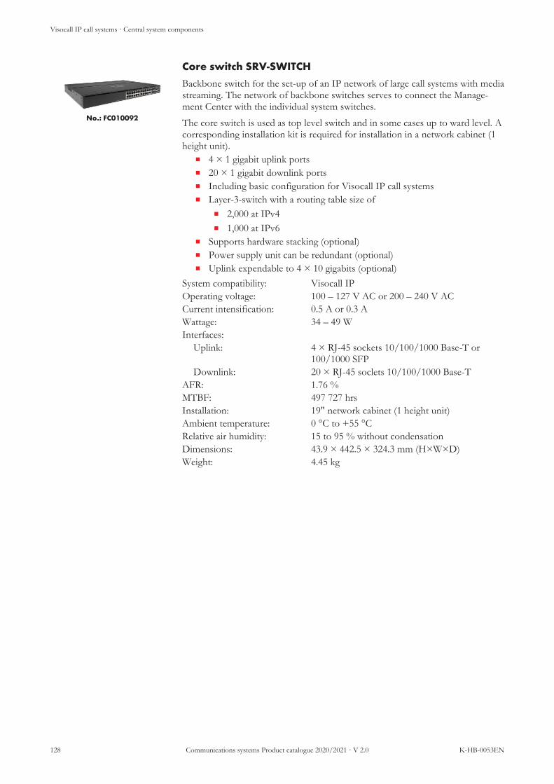
Visocall IP call systems · Central system components
128 Communications systems Product catalogue 2020/2021 · V 2.0 K-HB-0053EN
Core switch SRV-SWITCH
No.: FC010092
Backbone switch for the set-up of an IP network of large call systems with mediastreaming. The network of backbone switches serves to connect the Manage-ment Center with the individual system switches.The core switch is used as top level switch and in some cases up to ward level. Acorresponding installation kit is required for installation in a network cabinet (1height unit).
n 4 × 1 gigabit uplink portsn 20 × 1 gigabit downlink portsn Including basic configuration for Visocall IP call systemsn Layer-3-switch with a routing table size of
n 2,000 at IPv4n 1,000 at IPv6
n Supports hardware stacking (optional)n Power supply unit can be redundant (optional)n Uplink expendable to 4 × 10 gigabits (optional)
System compatibility: Visocall IPOperating voltage: 100 – 127 V AC or 200 – 240 V ACCurrent intensification: 0.5 A or 0.3 AWattage: 34 – 49 WInterfaces:
Uplink: 4 × RJ-45 sockets 10/100/1000 Base-T or100/1000 SFP
Downlink: 20 × RJ-45 soclets 10/100/1000 Base-TAFR: 1.76 %MTBF: 497 727 hrsInstallation: 19" network cabinet (1 height unit)Ambient temperature: 0 °C to +55 °CRelative air humidity: 15 to 95 % without condensationDimensions: 43.9 × 442.5 × 324.3 mm (H×W×D)Weight: 4.45 kg

Visocall IP call systems · Central system components
K-HB-0053EN Communications systems Product catalogue 2020/2021 · V 2.0 129
Ward/core switch ST-SWITCH
No.: 21-1000200-01
Backbone switch for the set-up of an IP network of call systems. The network ofbackbone switches serves to connect the Management Center with the individualsystem switches. The ward/core switch is applied at ward level. A correspondinginstallation kit is required for installation in a network cabinet (1 height unit).
n 24 × 1 gigabit portsn Including basic configuration for Visocall IP call systemsn Layer-3-switch with a routing table size of
n 2,000 at IPv4n 1,000 at IPv6
System compatibility: Visocall IPOperating voltage: 100 – 127 V AC or 200 – 240 V ACCurrent intensification: 0.6 A or 0.4 AWattage: 19.5 – 29.3 WInterfaces/ports: 24 × RJ-45 sockets 10/100/1000 Base-T and 4
× SFPAFR: 0.88 %MTBF: 995 455 hrsInstallation: 19" network cabinet (1 height unit)Ambient temperature: 0 °C to +45 °CRelative air humidity: 15 to 95 % without condensationDimensions: 43.9 × 442.5 × 200.2 mm (H×W×D)Weight: 2.41 kg
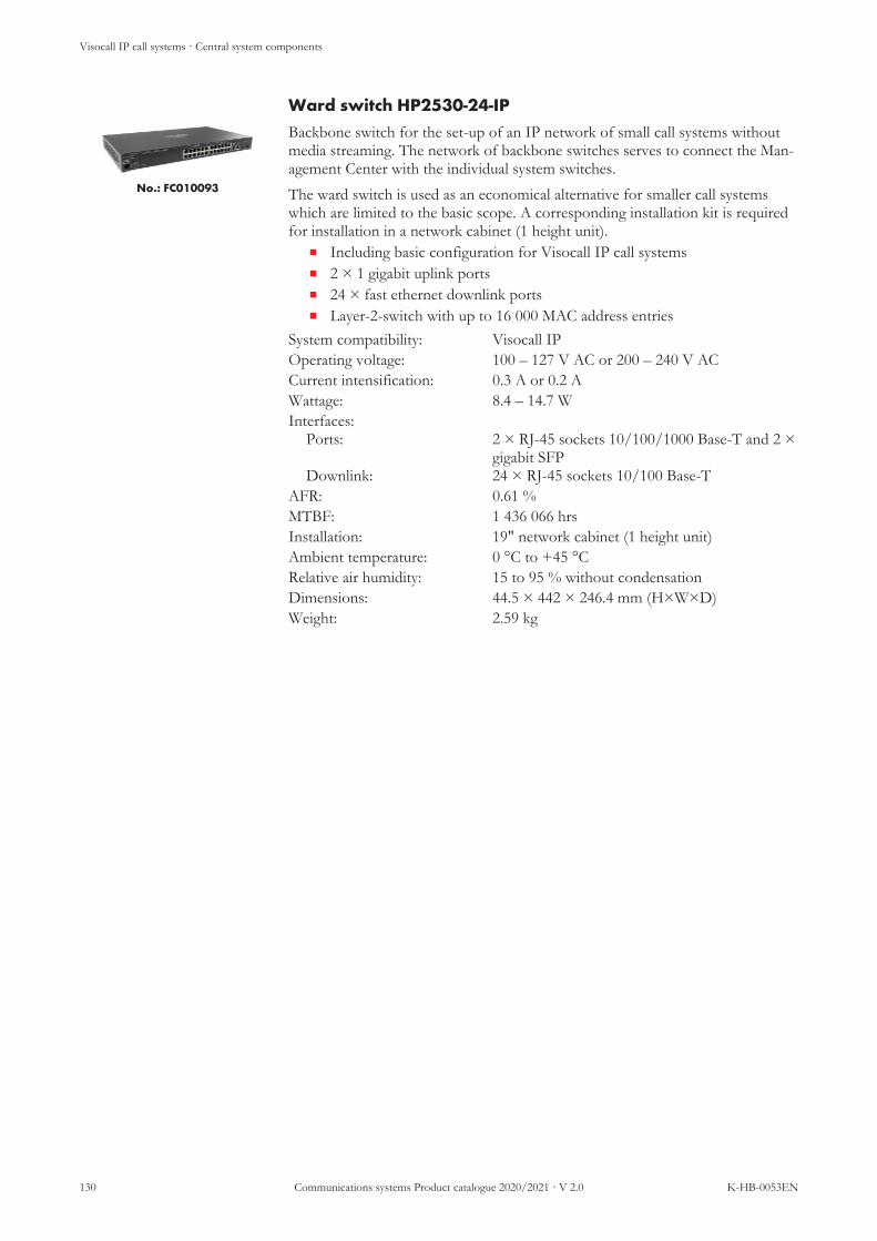
Visocall IP call systems · Central system components
130 Communications systems Product catalogue 2020/2021 · V 2.0 K-HB-0053EN
Ward switch HP2530-24-IP
No.: FC010093
Backbone switch for the set-up of an IP network of small call systems withoutmedia streaming. The network of backbone switches serves to connect the Man-agement Center with the individual system switches.The ward switch is used as an economical alternative for smaller call systemswhich are limited to the basic scope. A corresponding installation kit is requiredfor installation in a network cabinet (1 height unit).
n Including basic configuration for Visocall IP call systemsn 2 × 1 gigabit uplink portsn 24 × fast ethernet downlink portsn Layer-2-switch with up to 16 000 MAC address entries
System compatibility: Visocall IPOperating voltage: 100 – 127 V AC or 200 – 240 V ACCurrent intensification: 0.3 A or 0.2 AWattage: 8.4 – 14.7 WInterfaces:
Ports:
Downlink:
2 × RJ-45 sockets 10/100/1000 Base-T and 2 ×gigabit SFP24 × RJ-45 sockets 10/100 Base-T
AFR: 0.61 %MTBF: 1 436 066 hrsInstallation: 19" network cabinet (1 height unit)Ambient temperature: 0 °C to +45 °CRelative air humidity: 15 to 95 % without condensationDimensions: 44.5 × 442 × 246.4 mm (H×W×D)Weight: 2.59 kg

Visocall IP call systems · Central system components
K-HB-0053EN Communications systems Product catalogue 2020/2021 · V 2.0 131
Logical delivery point LDP
No.: 21-1000100-01
Component optimised for rack installation for breaking down a Visocall IP sys-tem into smaller partial segments. Connected between a Management Center andthe remaining network structure, a LDP increases the reliability of the call systemand facilitates its maintenance. If the function range of a Management Center isnot required for a call system, a LDP can be used instead.Installation in a network cabinet (1 height unit) is possible without accessories.Starting from application kit 6.0, a Logical Delivery Point can be provided withhardware redundancy. For this, the system extension software licence MMC re-dundancy and a second logical delivery point are required.
NOTE
The supplied Visocall IP software corresponds to the most recentlyreleased version of the application kit at the time of supply. Licencesfor control panels and other system extensions as well as the follow-ing versions of the application kit can be purchased separately.
n In call systems with more than 2000 IP components the use of LPDalongside the Management Center is imperative
n Up to 1000 IP components can be connected behind every LPDn The use of LDP increases the reliability of the call system and facilities its
maintenancen An LDP can be used instead of a Management Center if only the follow-
ing Management Center functions are required:n Central import of updatesn Automatic configuration of components when plugged in (e.g. ex-
change of a damaged patient terminal by the staff)System compatibility: Visocall IPOperating voltage: 207 – 264 V ACPower consumption: max. 50 WPower consumption: max. 1.1 A (75 A input surge current:)Interfaces:
System connection: 1 × RJ-45 socket for the connection of the nexthigher logical unit, e.g. a Management Center(1000 base TX interface)
IP backbone: 4 × RJ-45 sockets for the connection of logicallydownstream switches, e.g. backbone switches(100 base TX interface)
Service interface: 1 × RJ-45 socket for configurationInstallation: 19" network cabinet (1 height unit)Ambient temperature: 0 °C to +45 °CRelative air humidity: 10 to 90 % without condensationDimensions:
Case:Faceplate
43.7 × 448.6 × 224 mm (H×W×D)482,6 mm (W)
Weight: 3.1 kg

Visocall IP call systems · Central system components
132 Communications systems Product catalogue 2020/2021 · V 2.0 K-HB-0053EN
Management Center MC-IP
No.: 21-1000001-01
For the rack installation of optimised server incl. operating system and the soft-ware required for the operation of a Visocall IP call system. The server acts asthe centralised node for all kinds of external systems and takes over key func-tions for the entire call system. The Management Center is connected with thesystem switches via the network of backbone switches.Starting from application kit 6.0, a Management Center can be provided withhardware redundancy. For his, two Management Centers must be ordered in twodifferent versions (master and slave). In addition, the system extension softwarelicence MMC redundancy is required.
NOTE
The supplied Visocall IP software corresponds to the most recentlyreleased version of the application kit at the time of supply. Licencesfor control panels and other system extensions as well as the follow-ing versions of the application kit can be purchased separately.
A Management Center is required for the following application scenarios:n Connection of external systems (e.g. alarm server, fire alarm system, de-
mentia safety system, VDECT, telephone server,)n Operation of multimedia services via the server structure of the call sys-
temn Use of dongle protected software licencesn Central import of updatesn Automatic configuration of components when plugged in (e.g. exchange
of a damaged patient terminal by the staff)n Logging of events (event database)n Operation of a ward and centralised control paneln Use of the following system extensions
n Audio Managern MMC redundancyn Patient managementn System Monitorn Telephone book function
System compatibility: Visocall IPOperating voltage: 100 – 240 V ACCurrent intensification: max. 4,5 A (100 V AC) or 2 A (240 V AC)Interfaces/system connection: 2 × 1 Gbit/s RJ-45 socketsInstallation: 19" network cabinet (1 height unit)Heat dissipation: 950.4 kJ/hAmbient temperature: +5 °C to +45 °CRelative air humidity: 10 to 85 % without condensationDimensions:
Case:Faceplate:
42.8 × 435.4 × 572 mm (H×W×D)482,6 mm (W)
Weight: max. 13 kg (dependent on configuration)

Visocall IP call systems · Central system components
K-HB-0053EN Communications systems Product catalogue 2020/2021 · V 2.0 133
Management Center Desktop MC-IP-D
No.: 21-1000000-01
Server incl. operating system optimised for rack installation and for the operationof the software required in a Visocall IP call system. The server acts as the cent-ralised node for all kinds of external systems and takes over key functions for theentire call system. The Management Center is connected with the systemswitches via the network of backbone switches.Starting from application kit 6.0, a Management Center can be provided withhardware redundancy. For his, two Management Centers must be ordered in twodifferent versions (master and slave). In addition, the system extension softwarelicence MMC redundancy is required.
NOTE
The supplied Visocall IP software corresponds to the most recentlyreleased version of the application kit at the time of supply. Licencesfor control panels and other system extensions as well as the follow-ing versions of the application kit can be purchased separately.
A Management Center is required for the following application scenarios:n Connection of external systems (e.g. alarm server, fire alarm system, de-
mentia safety system, VDECT, telephone server,)n Operation of multimedia services via the server structure of the call sys-
temn Use of dongle protected software licencesn Central import of updatesn Automatic configuration of components when plugged in (e.g. exchange
of a damaged patient terminal by the staff)n Logging of events (event database)n Operation of a ward and centralised control paneln Use of the following system extensions
n Audio Managern MMC redundancyn Patient managementn System Monitorn Telephone book function
System compatibility: Visocall IPOperating voltage: 100 – 240 V ACCurrent intensification: max. 5 A (100 V AC) or 2.5 A (240 V AC)Interfaces/system connection: 2 × 1 Gbit/s RJ-45 socketsHeat dissipation: 831.6 kJ/hAmbient temperature: +5 °C to +45 °CRelative air humidity: 10 to 85 % without condensationDimensions: 340 × 98 × 399 mm (H×W×D) without baseWeight: max. 10 kg (dependent on configuration)

Visocall IP call systems · Central system components
134 Communications systems Product catalogue 2020/2021 · V 2.0 K-HB-0053EN
Sound Interface SDI
No.: 21-1001200-01
The module can be equipped with up to eight sound interface controllers SIC, toimport audio signals into a call system. Enables the import of up to 16 audio sig-nals into a call system.For operation, at least one sound interface controller SIC is needed. The soundinterface SDI consists of a metal cabinet with integrated module rack, powersupply unit, fan, antenna amplifier and antenna splitter.
n Built-in sound interface controllers SIC are supplied via the integrated an-tenna amplifier and splitter
n Several sound interface SDI can be connected in call systemsSystem compatibility: Visocall IPOperating voltage: 207 – 253 V ACWattage: 40 W typ. (equipped with 8 SIC)
max. 95 W (equipped with 8 SIC)Interfaces:
Aerial input: 1 × F antenna socket (recommended level 35dBμV)
Aerial output: 16 × F antenna socketsInstallation: Surface mountingAmbient temperature: 0 °C to +40°CRelative air humidity: up to 95 % without condensationDimensions: 600 × 445 × 225 mm (H×W×D)
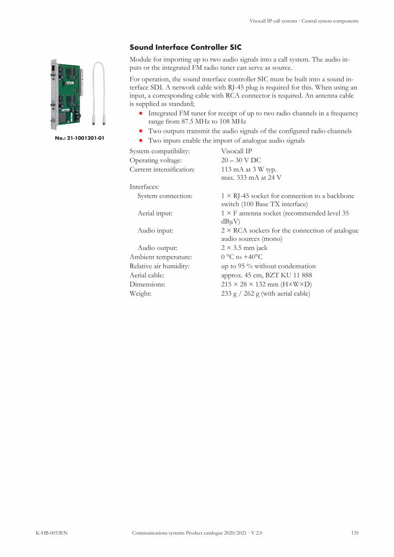
Visocall IP call systems · Central system components
K-HB-0053EN Communications systems Product catalogue 2020/2021 · V 2.0 135
Sound Interface Controller SIC
No.: 21-1001201-01
Module for importing up to two audio signals into a call system. The audio in-puts or the integrated FM radio tuner can serve as source.For operation, the sound interface controller SIC must be built into a sound in-terface SDI. A network cable with RJ-45 plug is required for this. When using aninput, a corresponding cable with RCA connector is required. An antenna cableis supplied as standard;
n Integrated FM tuner for receipt of up to two radio channels in a frequencyrange from 87.5 MHz to 108 MHz
n Two outputs transmit the audio signals of the configured radio channelsn Two inputs enable the import of analogue audio signals
System compatibility: Visocall IPOperating voltage: 20 – 30 V DCCurrent intensification: 113 mA at 3 W typ.
max. 333 mA at 24 VInterfaces:
System connection: 1 × RJ-45 socket for connection to a backboneswitch (100 Base TX interface)
Aerial input: 1 × F antenna socket (recommended level 35dBμV)
Audio input: 2 × RCA sockets for the connection of analogueaudio sources (mono)
Audio output: 2 × 3.5 mm jackAmbient temperature: 0 °C to +40°CRelative air humidity: up to 95 % without condensationAerial cable: approx. 45 cm, BZT KU 11 888Dimensions: 215 × 28 × 132 mm (H×W×D)Weight: 233 g / 262 g (with aerial cable)

Visocall IP call systems · Central system components
136 Communications systems Product catalogue 2020/2021 · V 2.0 K-HB-0053EN
Centralised system components and accessories
Label Type Article no.
System switch SWI9-GBIT L4-SWI9-GBIT 21-1000402-01
Case for SWI9For the protection of a system switch against mech-anical damage. For wall and ceiling mounting.
G-SWI9 DF010008
19“ installation rack for SWI9incl. 16 x guide holders. For the installation in a 19“network cabinet (6 height unit). With room for up to8 system switches
SWI9-RACK FC010009
Guide holder installation rack, 1 pc. (replace-ment) FH-MR DF010009
Core switch SRV-SWITCH FC010092
Ward/core switch ST-SWITCH ST-SWITCH 21-1000200-01
Ward switch HP2530-24-IP FC010093
HPE Aruba Transceiver X1211000 Base-LX Modul singlemode 1G SFP LC LX 21-1000350-01
HPE Aruba Transceiver X121 1G100 Base-SX Modul multimode 1G SFP LC SX DF010091-ALWL
Logical Delivery Point LDP 21-1000100-01
Management Center including operating systemand softwareManagement Center
MC-IP 21-1000001-01
Management Center including operating systemand softwareManagement Center Master
MC-IP-M 21-1000001-02
Management Center including operating systemand softwareManagement Center Slave
MC-IP-S 21-1000001-03
Management Center Desktop including operat-ing system and softwareManagement Center Desktop
MC-IP-D 21-1000000-01
Management Center Desktop including operat-ing system and softwareManagement Center Desktop Master
MC-IP-D-M 21-1000000-02

Visocall IP call systems · Central system components
K-HB-0053EN Communications systems Product catalogue 2020/2021 · V 2.0 137
Label Type Article no.
Management Center Desktop including operat-ing system and softwareManagement Center Desktop Slave
MC-IP-D-S 21-1000000-03
Sound Interface SDI SDI 21-1001200-01
Sound Interface Controller SIC SIC 21-1001201-01
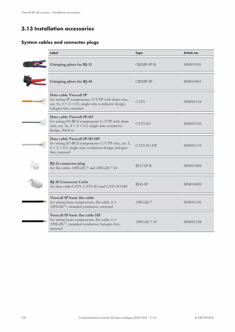
Visocall IP call systems · Installation accessories
138 Communications systems Product catalogue 2020/2021 · V 2.0 K-HB-0053EN
3.13 Installation accessories· Installation accessories
System cables and connector plugs
Label Type Article no.
Crimping pliers for RJ-12 CRIMP-IP-B MM011001
Crimping pliers for RJ-45 CRIMP-IP MM010001
Data cable Visocall IPfor wiring IP components, F/UTP with drain wire,cat. 5e, 4 × 2 × 0.5, single-wire conductor design,halogen-free, metered
CAT5 MM001124
Data cable Visocall IP-IOfor wiring IO-BUS components U/UTP with drainwire, cat. 5e, 4 × 2 × 0.5, single-wire conductordesign, 304.8 m
CAT5-IO MM001125
Data cable Visocall IP-IO HFfor wiring IO-BUS components U/UTP wire, cat. 5,4 × 2 × 0.5, single-wire conductor design, halogen-free, metered
CAT5-IO-HF MM001135
RJ-12 connector plugfor flat cables AWG28/7 and AWG28/7-H RJ12-IP-B MM011008
RJ-45 Connector Cat5efor data cable CAT5, CAT5-IO and CAT5-IO-HF RJ45-IP MM010008
Visocall IP basic flat cablefor wiring basic components, flat cable, 6 ×AWG28/7, stranded conductor, metered
AWG28/7 MM001126
Visocall IP basic flat cable HFfor wiring basic components, flat cable, 6 ×AWG28/7, stranded conductor, halogen-free,metered
AWG28/7-H MM001128

Visocall IP call systems · Installation accessories
K-HB-0053EN Communications systems Product catalogue 2020/2021 · V 2.0 139
Fitting materials
Label Type Article no.
AP case AP-1 APA-1 FC008991
AP case AP-2 APA-2 FC008992
Case frame DR-KMT FC010191
Cavity wall double switchbox H2 FC88013
Cavity wall switchbox H1 21-2400000-01
Cavity wall switchbox H-ICT-IP FC88018
Countersunk double switchbox U2 FC88012
Countersunk switchbox U1 FC88010
Countersunk switchbox U-ICT-IP FC88019
Installation frame for countersunk mounting RFID-GH-UPR EI931618
Installation frame for surface mounting RFID-GH-APR EI931617
Nurse call sign blue/white S LTR FC38100
Surface mounted frame AP-KMT FC010190
Wall-mounted bracket for TXT TXT-WH EI931149
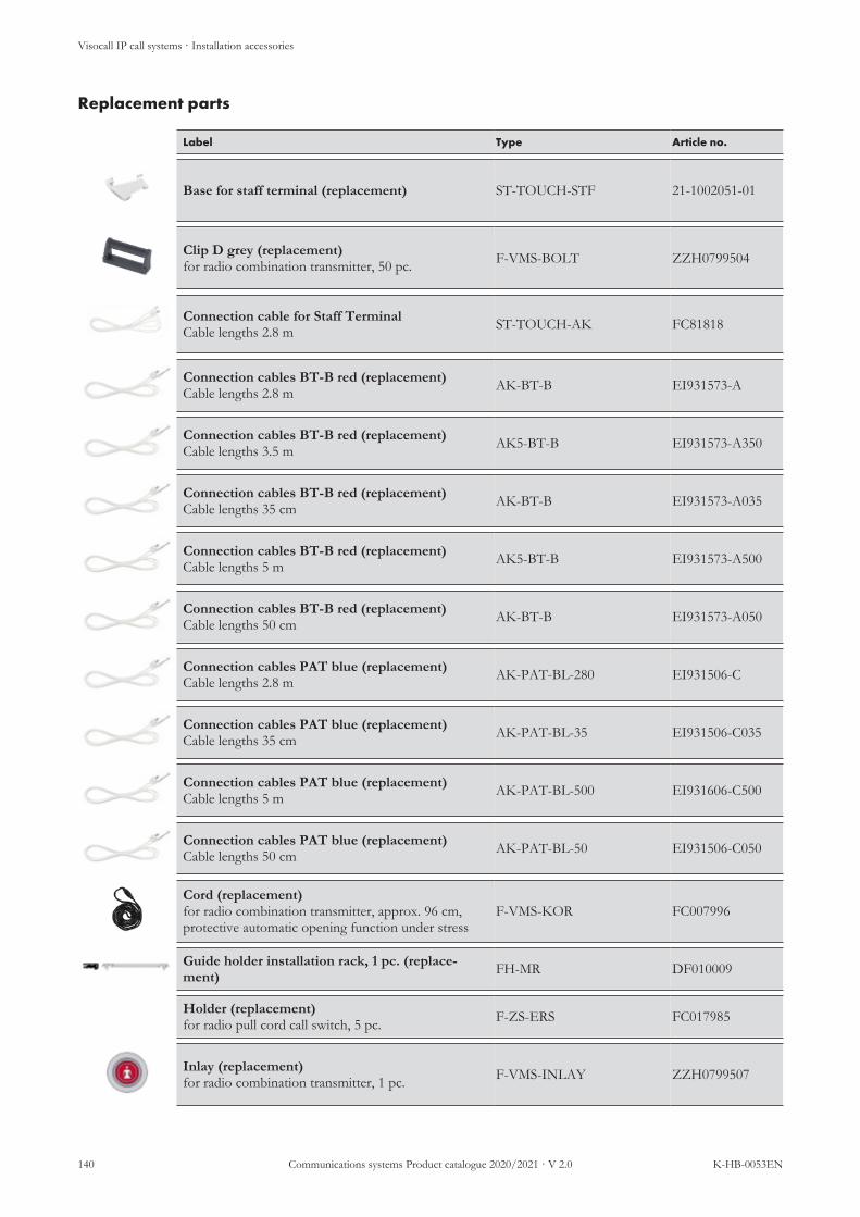
Visocall IP call systems · Installation accessories
140 Communications systems Product catalogue 2020/2021 · V 2.0 K-HB-0053EN
Replacement parts
Label Type Article no.
Base for staff terminal (replacement) ST-TOUCH-STF 21-1002051-01
Clip D grey (replacement)for radio combination transmitter, 50 pc. F-VMS-BOLT ZZH0799504
Connection cable for Staff Terminal Cable lengths 2.8 m ST-TOUCH-AK FC81818
Connection cables BT-B red (replacement)Cable lengths 2.8 m AK-BT-B EI931573-A
Connection cables BT-B red (replacement)Cable lengths 3.5 m AK5-BT-B EI931573-A350
Connection cables BT-B red (replacement)Cable lengths 35 cm AK-BT-B EI931573-A035
Connection cables BT-B red (replacement)Cable lengths 5 m AK5-BT-B EI931573-A500
Connection cables BT-B red (replacement)Cable lengths 50 cm AK-BT-B EI931573-A050
Connection cables PAT blue (replacement)Cable lengths 2.8 m AK-PAT-BL-280 EI931506-C
Connection cables PAT blue (replacement)Cable lengths 35 cm AK-PAT-BL-35 EI931506-C035
Connection cables PAT blue (replacement)Cable lengths 5 m AK-PAT-BL-500 EI931606-C500
Connection cables PAT blue (replacement)Cable lengths 50 cm AK-PAT-BL-50 EI931506-C050
Cord (replacement)for radio combination transmitter, approx. 96 cm,protective automatic opening function under stress
F-VMS-KOR FC007996
Guide holder installation rack, 1 pc. (replace-ment) FH-MR DF010009
Holder (replacement)for radio pull cord call switch, 5 pc. F-ZS-ERS FC017985
Inlay (replacement)for radio combination transmitter, 1 pc. F-VMS-INLAY ZZH0799507

Visocall IP call systems · Installation accessories
K-HB-0053EN Communications systems Product catalogue 2020/2021 · V 2.0 141
Label Type Article no.
PAT spiral connection cable (replacement)with 33 cm connection cable and RJ-45 connectorplug
AK-PAT-BL-SPIRALE 21-1011250-01
Pneumatic handheld button (replacement)with connection hose 2.2 m PT-BI EI931140
Pull cord call switch cord red incl. snap hookand grip, 10 pcs. (replacement)Pull cord length 2.3 m
ZT-S2-E 21-1002300-01
Pull cord call switch cord red incl. snap hookand grip, 10 pcs. (replacement)Pull cord length 4 m
ZT-S4-E 21-1002300-02
Pull cord call switch cord red incl. snap hook, 10pcs. (replacement)Pull cord length 2.3 m
ZT-S2 21-1002301-01
Radio transmitter insert (replacement)for installation in a wireless contact mat, 869 MHz,incl. Batterie (CR2032)
RTM-L869 21-2200550-01
Receiver for Staff Terminal (replacement)including connection cables ST-TOUCH-HK 21-1002050-01
Repair complete kit (replacement)for radio combination transmitter, 13 pcs. à 5 sets F-VMS-RKS ZZH0799506
Repair kit (replacement)for radio combination transmitter, 10 pcs. à 10 sets F-VMS-ERS ZZH0799505
Replacement ball and hose (replacement)for radio pneumatic ball-type button F-PS-869 F-PS-EK FC017989
Replacement parts MediPad (replacement)consists of 1 × pillowcase, 2 × velcro straps, 4 × ad-hesive dots
F-MP-ES ZZL10740
Seal (replacement)for radio combination transmitter, 1 pc. F-VMS-ED ZZH0799508
Stretch wristband (replacement)for radio combination transmitter, 1 pc. length 24cm, with clip fastener
F-VMS-BAND-24 FC007957-B
Stretch wristband (replacement)for radio combination transmitter, 1 pc. length 27cm, with clip fastener
F-VMS-BAND-27 FC007957-B_27

Visocall IP call systems · Installation accessories
142 Communications systems Product catalogue 2020/2021 · V 2.0 K-HB-0053EN
Accessories
Label Type Article no.
Aluminium base for cradle K-PAT K-PAT-AS 21-1002200-01
Blind cover, connection module, 10 pcs.For multimedia and diagnostic sockets, not suited forIntellifix sockets!
BLA-SM FC010295
Cable for TVI-IP (SAMSUNG)Length 1.5 m, RJ-12 straight, DIN straight, jackangled
K-TVI-SAMSUNG 21-1002030-01
Cable for TVI-IP (SAMSUNG)Length 1.5 m, RJ-12 straight, DIN angled, jackangled
K-TVI-SAMSUNG-2 21-1002030-02
Cable for TVI-IP PHILIPSLength 1.5 m, SCART connector, connection strip K-TVI-PHILIPS 21-1002031-01
Cable for TVI-IP PHILIPSRJ-45, DIN, jack straight, 1.5 m K-TVI-PHILIPS-2 21-1002031-02
Cable for TVI-IP PHILIPSRJ-45, DIN, jack straight, 3 m K-TVI-PHILIPS-3 21-1002031-03
Cable for TVI-IP PHILIPSRJ-45, DIN, jack straight, 4 m K-TVI-PHILIPS-4 21-1002031-04
Cable for TVI-IP PHILIPSRJ-45, DIN, jack bent, 1.5 m K-TVI-PHILIPS-5 21-1002031-05
Cradle K-PAT K-PAT FC010240
Diagnostic connection cable DSTK-W-VCIP FC010350
External transmission adapterfor equipping a wired CareMat with radio transmis-sion, 869 MHz, battery-operated (CR2032)
F-SAD-869 FC017998
GooseneckFor mounting a K-PAT cradle to a standard rail SH-GTS ZZL10737
Headphones with headbandCable lengths 2 m KH FC005205
Holding clipFor attaching a device cable to a bed sheet HC-VC FC12804

Visocall IP call systems · Installation accessories
K-HB-0053EN Communications systems Product catalogue 2020/2021 · V 2.0 143
Label Type Article no.
Holding clip for connection cableFor attaching several device cables to the bed frame HB-VC FC12805
Holding clip for PATFor attaching a patient terminal or a BT-IP pearpushbutton to the side rail of a bed
HB-PAT 21-1002005-01
Holding clip for PATFor attaching a device cable to a cable HC-PAT 21-1002006-01
HPE Aruba Transceiver X1211000 Base-LX Modul singlemode 1G SFP LC LX 21-1000350-01
HPE Aruba Transceiver X121 1G100 Base-SX Modul multimode 1G SFP LC SX DF010091-ALWL
Microphone USBfor Announcements and calls MIC-USB FC010074
Mifare card MFC4C-CD 21-1002500-01
Mifare Reader USBfor reading Mifare cards MFR-3700 FC017330
Mounting bracketFor attaching a device cable to a cable HKL VCP FC006209
Mounting clipFor attaching a device cable to a rising aid HL27-VC FC12803--A
Mounting clipFor attaching a device cable to a rising aid HL38-VC FC12803--B
Network isolator EMOSAFE EMOSAFE EN-70E 21-1000500-01
Null modem cablewith two D-SUB DE9 connector plugs for the con-nection of two control panels via RS-232, cablelengths 2 m
DB9-2M 21-9031000-01
Null modem cablewith two D-SUB DE9 connector plugs for the con-nection of two control panels via RS-232, cablelengths 3 m
DB9-3M 21-9031001-01

Visocall IP call systems · Installation accessories
144 Communications systems Product catalogue 2020/2021 · V 2.0 K-HB-0053EN
Label Type Article no.
VOIP receiverfor speech functions and announcements VOIP-H FC010071
Wall-mounted bracket MediTouchfor the magnetic fastening of a MediTouch product MEDITOUCH-WH 21-2200110-01
Wall-mounted bracket V2 for VR6Wall-mounted bracket V2 for VR6 for fastening a ra-dio receiver (VR6-5 or VR6-5 DIN-NT)
VR6-WALL FC017978

Visocall IP call systems · Software licences
K-HB-0053EN Communications systems Product catalogue 2020/2021 · V 2.0 145
3.14 Software licences· Software licences
Label Type Article no.
Licence for the operation of a control panelSoftware licence ward control panel SWP-IP/SLS FC008050
Licence for the operation of a control panelSoftware licence ward control panel extension SWP-IP/SLS-E FC008052
Licence for the operation of a control panelSoftware licence centralised control panel SWP-IP/ZLS FC010053
Licence for the operation of a control panelSoftware licence centralised control panel extension SWP-IP/ZLS-E FC010054
Software licence Audio Manager SWP-IP/AM FC010065
Software licence event database SWP-IP/EDB FC010056
Software licence for telecommunications system SWP-IP/TK FC010060
Software licence for using interfacesSoftware licence ESPA interface SWP-IP/ESPA FC010045
Software licence for using interfacesSoftware licence alarm server SWP-IP/AS FC010057
Software licence for using interfacesSoftware licence fire alarm system SWP-IP/BMZ FC010059
Software licence for using interfacesSoftware licence mobile telephone end devices SWP-IP/MP FC008042
Software licence for using interfacesSoftware licence dementia protection system SWP-IP/DESO FC010058
Software licence for using interfacesSoftwarelizenz internet server SWP-IP/WEB FC010062
Software licence for using interfacesSoftwarelizenz OPC server SWP-IP/OPC FC010068
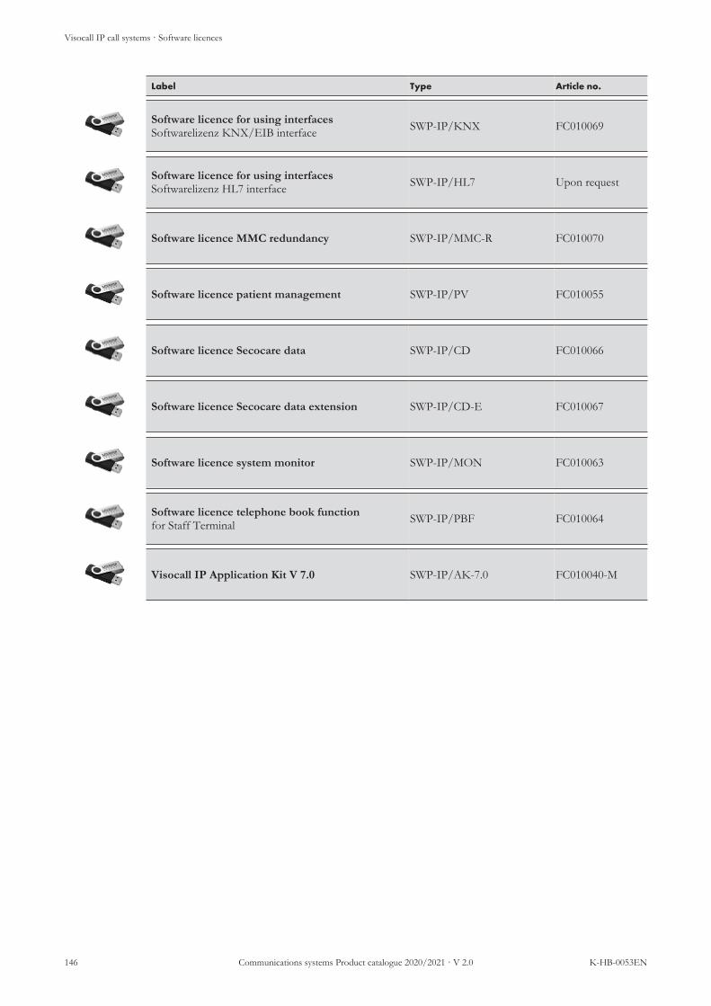
Visocall IP call systems · Software licences
146 Communications systems Product catalogue 2020/2021 · V 2.0 K-HB-0053EN
Label Type Article no.
Software licence for using interfacesSoftwarelizenz KNX/EIB interface SWP-IP/KNX FC010069
Software licence for using interfacesSoftwarelizenz HL7 interface SWP-IP/HL7 Upon request
Software licence MMC redundancy SWP-IP/MMC-R FC010070
Software licence patient management SWP-IP/PV FC010055
Software licence Secocare data SWP-IP/CD FC010066
Software licence Secocare data extension SWP-IP/CD-E FC010067
Software licence system monitor SWP-IP/MON FC010063
Software licence telephone book functionfor Staff Terminal SWP-IP/PBF FC010064
Visocall IP Application Kit V 7.0 SWP-IP/AK-7.0 FC010040-M
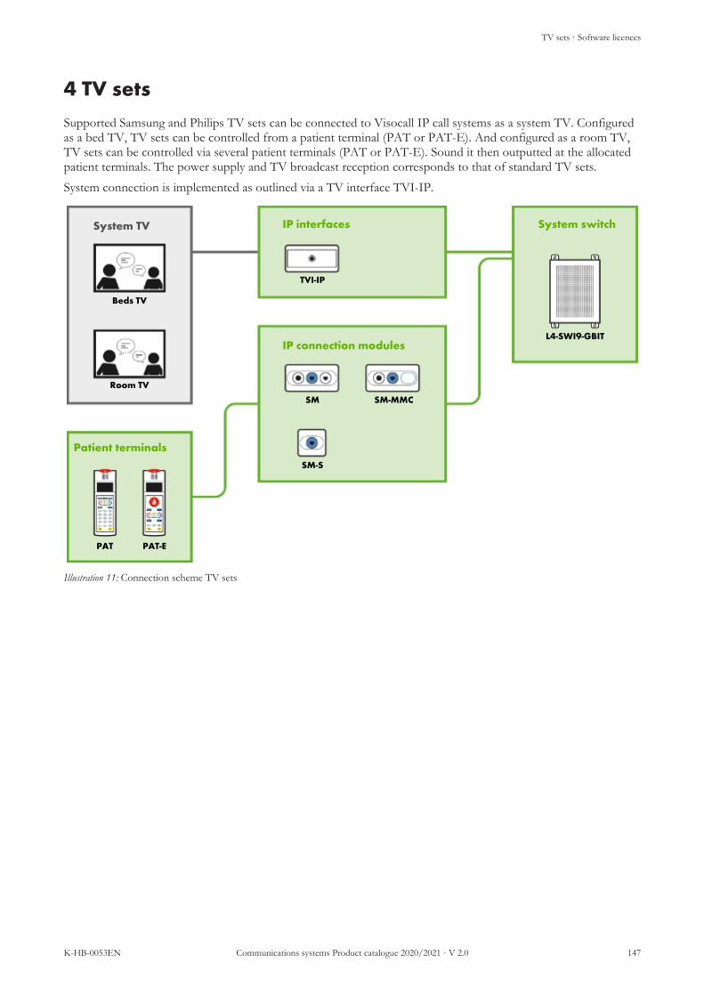
TV sets · Software licences
K-HB-0053EN Communications systems Product catalogue 2020/2021 · V 2.0 147
4 TV setsSupported Samsung and Philips TV sets can be connected to Visocall IP call systems as a system TV. Configuredas a bed TV, TV sets can be controlled from a patient terminal (PAT or PAT-E). And configured as a room TV,TV sets can be controlled via several patient terminals (PAT or PAT-E). Sound it then outputted at the allocatedpatient terminals. The power supply and TV broadcast reception corresponds to that of standard TV sets.System connection is implemented as outlined via a TV interface TVI-IP.
System TV IP interfaces
IP connection modules
System switch
Patient terminals
Beds TV
Room TV
PAT PAT-E
TVI-IP
SM SM-MMC
SM-S
L4-SWI9-GBIT
Illustration 11: Connection scheme TV sets

TV sets · Philips TV sets
148 Communications systems Product catalogue 2020/2021 · V 2.0 K-HB-0053EN
4.1 Philips TV sets· Philips TV sets
The following Philips TV sets can be integrated in Visocall IP call systems. The 19“ 19HFL5014W/12 set can beconfigured as a bed TV, all other models can be configured as room TV.For control via a patient terminal, each TV must be connected to the call system via a TV interface TVI-IP. Thepower supply and TV broadcast reception corresponds to that of standard TV sets.The 19“ 19HFL5014W/12 set is suited for wall and ceiling arm mounting, the room TVs are suited for wall-mounting using a compatible VESA mounting bracket.
Product overview
19HFL5014W/12 32HFL5014 43HFL5014 50HFL5014
Beds TV Room TV Room TV Room TVDiagonal screen size 19″ 32″ 43″ 50″Backlight LED LEDScreen resolution in pixel 1366 × 768 1920 × 1080 1920 × 1080 1920 × 1080Terrestrial TV tuner DVB-T/T2/C DVB-T2Cable TV tuner - DVB-CAnalogue TV tuner • • • •IP-TV • • • •Operating voltage VAC 100 – 240 V AC 220 – 240 VPower supply with EU energy label
18 W 29 W 48 W 49 W
VESA wall mounting in mm 75 × 75 100 × 100 200 × 200 200 × 200VESA screw size M4 M6 M6 M6Weight with base - 4.7 kg 7.3 kg 11.6 kgWeight without base 3.8 kg 4.6 kg 7.2 kg 11.3 kg

TV sets · Philips TV sets
K-HB-0053EN Communications systems Product catalogue 2020/2021 · V 2.0 149
Philips TV sets and accessories
Label Type Article no.
Philips Media Suite TV 32″VESA 100 × 100 mm, 4.7 kg/4.6 kg 32HFL5014 21-2010002-01
Philips Media Suite TV 43″VESA 200 × 200 mm, 7.3 kg/7.2 kg 43HFL5014 21-2010003-01
Philips Media Suite TV 50″VESA 200 × 200 mm, 11.6 kg/11.3 kg 50HFL5014 21-2010004-01
TV mounting bracket WALL 1120Flat TV mounting bracket with 1 pivot, VESA 100 ×100 mm, VESA 200 × 200 mm, pivotable by max. –30°/+30°, inclinable by max. 10°, load capacity max.15 kg
WALL-1120 FC007113
TV mounting bracket WALL 2225TV mounting bracket with 2 pivots, VESA 100 ×100mm, VESA 200 × 200mm, pivotable by max.-60°/+60°, inclinable by max. 20°, load capacity max.20 kg
WALL-2225B FC007115
Philips beds TV 19"LED HD TV with 47 cm diagonal screen size 19HFL5014W/12 21-2010050-01
Wall-mounted arm FX500 Schrackincl. wall console FX850 for Philips beds TV FX500-FX850 21-2015000-01
Wall console FX850for wall-mounted arm FX500 (replacement) FX850 21-2015001-01
Cover hinge for wall-mounted arm FX500 (replacement) FX500 CV 21-2010103-01
Cable for TVI-IP PHILIPSRJ-45, DIN, jack bent, 1.5 m K-TVI-PHILIPS-5 21-1002031-05
Cable for TVI-IP PHILIPSRJ-45, DIN, jack straight, 1.5 m K-TVI-PHILIPS-2 21-1002031-02
Cable for TVI-IP PHILIPSRJ-45, DIN, jack straight, 3 m K-TVI-PHILIPS-3 21-1002031-03
Cable for TVI-IP PHILIPSRJ-45, DIN, jack straight, 4 m K-TVI-PHILIPS-4 21-1002031-04
TV interface TVI-IP TVI-IP 21-1013001-01

TV sets · Philips TV sets
150 Communications systems Product catalogue 2020/2021 · V 2.0 K-HB-0053EN
Label Type Article no.
Countersunk double switchbox U2 FC88012
Cavity wall double switchbox H2 FC88013
AP case AP-2 APA-2 FC008992

TV sets · Samsung TV sets
K-HB-0053EN Communications systems Product catalogue 2020/2021 · V 2.0 151
4.2 Samsung TV sets· Samsung TV sets
The following Samsung TV sets can be integrated in Visocall IP call systems and configured as room TV.For control via a patient terminal, each TV must be connected to the call system via a TV interface TVI-IP. Thepower supply and TV broadcast reception corresponds to that of standard TV sets. Suited for wall-mounting withcompatible VESA holder.
Product overview
Features HG
32EE
690D
B
HG
43EE
690D
B
HG
32EE
590F
K
HG
40EE
590S
K
HG
32EF
690D
B
HG
43EF
690D
B
Diagonal screen size 32″ 43″ 32″ 40″ 32″ 43″Backlight LEDScreen resolution in pixel 1920 × 1080 1920 × 1080 1366 × 768 1920 × 1080 1920 × 1080 1920 × 1080Terrestrial TV tuner DVB-T2Cable TV tuner DVB-CSatellite TV tuner DVB-S2Analogue TV tuner • • • • • •HbbTV • • • • HbbTV 1.5 HbbTV 1.5Operating voltage VAC 220 – 240 VPower in operation 85 W 95 W 60 W 90 W 85 W 95 WVESA wall mountingin mm
100 × 100 200 × 200 100 × 100 200 × 200 100 × 100 200 × 200
VESA screw size M4 M8 M4 M8 M8 M8Weight with base 7.1 kg 12.3 kg 5.8 kg 10.6 kg 7.3 kg 12.7 kgWeight without base 5.5 kg 9.4 kg 4.3 kg 7.7 kg 5.7 kg 9.7 kg

TV sets · Samsung TV sets
152 Communications systems Product catalogue 2020/2021 · V 2.0 K-HB-0053EN
Samsung TV sets and accessories
Label Type Article no.
Samsung Hotel TV 32″ 32HE690VESA 200 × 200 mm, 7.1 kg/5.5 kg HG32EE690DB 21-2020000-01
Samsung Hotel TV 43″ 43HE690VESA 200 × 200 mm, 12.3 kg/9.4 kg HG43EE690DB 21-2020001-01
Samsung Hotel TV 32″ 32HE590FVESA 100 × 100 mm, 5.8 kg/4.3 kg HG32EE590FK 21-2020002-01
Samsung Hotel TV 40″ 40HE590VESA 200 × 200 mm, 10.6 kg/7.7 kg HG40EE590SK 21-2020003-01
Samsung Hotel TV 32″ 32HF690VESA 100 × 100 mm, 7.3 kg/5.7 kg HG32EF690DB 21-2020004-01
Samsung Hotel TV 43″ 43HF690VESA 100 × 100 mm, 12.7 kg/9.7 kg HG43EF690DB 21-2020005-01
TV mounting bracket WALL 1120Flat TV mounting bracket with 1 pivot, VESA 100 ×100 mm, VESA 200 × 200 mm, pivotable by max. –30°/+30°, inclinable by max. 10°, load capacity max.15 kg
WALL-1120 FC007113
TV mounting bracket WALL 2225TV mounting bracket with 2 pivots, VESA 100 ×100mm, VESA 200 × 200mm, pivotable by max.-60°/+60°, inclinable by max. 20°, load capacity max.20 kg
WALL-2225B FC007115
Cable for TVI-IP (SAMSUNG)Length 1.5 m, RJ-12 straight, DIN straight, jackangled
K-TVI-SAMSUNG 21-1002030-01
Cable for TVI-IP (SAMSUNG)Length 1.5 m, RJ-12 straight, DIN angled, jackangled
K-TVI-SAMSUNG-2 21-1002030-02
TV interface TVI-IP TVI-IP 21-1013001-01
Countersunk double switchbox U2 FC88012
Cavity wall double switchbox H2 FC88013

TV sets · Samsung TV sets
K-HB-0053EN Communications systems Product catalogue 2020/2021 · V 2.0 153
Label Type Article no.
AP case AP-2 APA-2 FC008992

Multimedia devices
154 Communications systems Product catalogue 2020/2021 · V 2.0 K-HB-0053EN
5 Multimedia devicesMultimedia terminals not only make watching TV from patients bed simpler but also offer patients and clinic staffprecisely the assistance they need around the clock: from TV, radio and Internet over medication assistance tomenu orders and interactive patient surveys.
Multimedia Tablet 13SF
No.: 21-2000111-01
Compact patient multimedia tablet for TV, radio and Internet directly from thepatient bed. Operation is simple and intuitive via the touchscreen and functionbutton. The sound can either be played over the integrated loudspeakers orheadphones. Its flush glass front enables the wipe disinfection of the completemultimedia tablet, with an extremely positive impact on hygiene.The device is mounted to a stable, flexibly adjustable wall-mounted arm or abedside cabinet pivot arm (not supplied as standard).
n LCD touch screen with 13.3“ diagonal screen sizen Brightness sensor for ambient lightn Capacitive operating keypad with optical and/or acoustic acknowledge-
ment for controlling the basic functions, e.g. programme selection,volume, room light
n IP TV/radio via LAN interfacen LED reading lightn Centralised configuration option
Screen:Diagonal width/format: 33.78 cm (13.3“)/16:9Resolution: 1920 × 1080 pxLight strength: 300 cd/m²Viewing angle: ± 89°
Processor: 1,6 GHz Quad-core ARM® Cortex™ 53operation without fan, passive cooling
Operating system: AOSP (Android Open Source Project)TV and radio: DVB-IPTV (Multicast UDP), HLS (Unicast
TCP)Sound: Integrated loudspeakerVideo formats: H.264, H.265, MPEG1, MPEG2, MPEG4Audio formats: Dolby® Digital™, Dolby® Digital
Plus™, MP2, MP3, AACEthernet: 10/100 MbitWLAN: WLAN IEEE 802.11ac, 2×2 MIMOBluetooth: Bluetooth 4.2Connections: 1 × RJ-45 socket (LAN IN)
1 × USB 3.01 × 3.5 mm jack for headphones
Power supply: 44-57VDC IEEE 802,3af/at (PoE/PoE+)Power consumption: max. 25.5 W (PoE+ operation)
max. 12.95 W (PoE+ operation)Case: white, ABS/PCDisplay frame: blackFront glass: Dragontrail™ GlassAmbient temperature: +5 °C to +40 °C without condensationDimensions: 230 × 340 × 33 mm (H×W×D)Weight: approx. 1.3 kg

Multimedia devices
K-HB-0053EN Communications systems Product catalogue 2020/2021 · V 2.0 155
Multimedia Tablet 16SF
No.: 21-2000121-01
Compact patient multimedia tablet for TV, radio and Internet directly from thepatient bed. Operation is simple and intuitive via the touchscreen and functionbutton. The sound can either be played over the integrated loudspeakers orheadphones. Its flush glass front enables the wipe disinfection of the completemultimedia tablet, with an extremely positive impact on hygiene.The device is mounted to a stable, flexibly adjustable wall-mounted arm or abedside cabinet pivot arm (not supplied as standard).
n LCD touch screen with 15.6“ diagonal screen sizen Brightness sensor for ambient lightn Capacitive operating keypad with optical and/or acoustic acknowledge-
ment for controlling the basic functions, e.g. programme selection,volume, room light
n IP TV/radio via LAN interfacen LED reading lightn Centralised configuration option
Screen:Diagonal width/format: 39.6 cm (15.6“)/16:9Resolution: 1920 × 1080 pxLight strength: 300 cd/m²Viewing angle: ± 89°
Processor: 1,6 GHz Quad-core ARM® Cortex™ 53operation without fan, passive cooling
Operating system: AOSP (Android Open Source Project)TV and radio: DVB-IPTV (Multicast UDP), HLS (Unicast
TCP)Sound: Integrated loudspeakerVideo formats: H.264, H.265, MPEG1, MPEG2, MPEG4Audio formats: Dolby® Digital™, Dolby® Digital
Plus™, MP2, MP3, AACEthernet: 10/100 MbitWLAN: WLAN IEEE 802.11ac, 2×2 MIMOBluetooth: Bluetooth 4.2Connections: 1 × RJ-45 socket (LAN IN)
1 × USB 3.01 × 3.5 mm jack for headphones
Power supply: 44-57VDC IEEE 802,3af/at (PoE/PoE+)Power consumption: max. 25.5 W (PoE+ operation)
max. 12.95 W (PoE+ operation)Case: white, ABS/PCDisplay frame: blackFront glass: Dragontrail™ GlassAmbient temperature: +5 °C to +40 °C without condensationDimensions: 230 × 340 × 33 mm (H×W×D)Weight: approx. 1.54 kg

Multimedia devices
156 Communications systems Product catalogue 2020/2021 · V 2.0 K-HB-0053EN
Bedside cabinet pivot arm S-IP-1013
No.: 21-2005010-01
Height adjustable bedside cabinet pivot arm for attaching the multimedia tablets13SF incl. connection cable.Terminal weight: max. 1.3 kgSpring force: mechanicalInclination range: -18°/+38°Inclination height: ca. -100/+200 mmInsertion pin height: 225 mmConnection cables: CAT.6Cabling: EIA/TIA 568 BCable length: 3.7 mCable colour: whiteMaterial: metalColour: white, similar to RAL 9010Dimensions: 550 × 370 × 100 mm (H×W×D)Weight: approx. 2.5 kg
Bedside cabinet pivot arm S-IP-16
No.: 21-2005012-01
Height adjustable bedside cabinet pivot arm for attaching the multimedia tablets16SF incl. connection cable.Terminal weight: max. 1.6 kgSpring force: mechanicalInclination range: -18°/+38°Inclination height: ca. -100/+200 mmInsertion pin height: 225 mmConnection cables: CAT.6Cabling: EIA/TIA 568 BCable length: 3.7 mCable colour: whiteMaterial: metalColour: white, similar to RAL 9010Dimensions: 550 × 370 × 100 mm (H×W×D)Weight: approx. 2.5 kg
Wall-mounted arm type 500 RJ-45– IP
No.: 21-2005401-01-01
Wall-mounted arm for attaching a multimedia tabletBearing load: 0.5 – 2.44 kgConnection cables: CAT.5, integrated
on the wall side: RJ-45 connector plugon the device side: RJ-45 connector plug
Cabling: Inside the wall-mounted arm through the wallbracket to the RJ-45 connection socket.
Monitor mount: VESA 75Material: metalColour: white, similar to RAL 9010Dimensions: Extension total: 1859 mm
Spring-loaded arm: 1175 mmBoom: 684 mm
Weight: approx. 9 kg

Multimedia devices
K-HB-0053EN Communications systems Product catalogue 2020/2021 · V 2.0 157
Wall bracket type 500
No.: 21-2005500-01-01
Wall bracket for wall-mounted arm Type 500Material: Metal (cover ABS)Colour: white, similar to RAL 9010Dimensions: 312 × 208 × 55 mm (H×W×D)Weight: approx. 4 kg
Connection circuit board 500 - 20W1
No.: 21-2005501-01-02
Connection circuit board for the electronical connection of the wall-mountedarm 500 RJ-45 - IPConnections: Cage Clamp technology, 0.2 – 1.5 mm² (AWG
24 – 16), single-wire conductor and wire-endsleeves directly pluggable
Fuse: 1 A (pluggable)Installation: inside the wall-mounted armDimensions: 96 × 58 × 1.6 mm (H×W×D)Weight: 90 g
Connect server MMNCS
No.: 21-2000001-01
Fully pre-installed and ready-to-operate server with hardware and software forthe centralised distribution of configurations to the mobile devices.Hardware: 19" mini server, 1 HU, short
Intel Atom 2 × 1.86 GHz4 GB RAM, 40 GB SSD
Software: Linux OS, BEWATEC Connect (VM), DHCPissuing of addresses
Connections: 2 × RJ-45 gigabit ports (LAN)8 × USB socket 2.02 × USB socket 3.01 × HDMI1 × VGA1 × PS/2
Operating voltage: 230 V AC/50 HzPower consumption: max. 200 WDimensions: 44 × 483 × 250 mm (H×W×D)Weight: approx. 3.5 kg

Multimedia devices
158 Communications systems Product catalogue 2020/2021 · V 2.0 K-HB-0053EN
5.1 Multimedia devices and accessories
Label Type Article no.
Multimedia Tablet 13SFincluding operating system and reading light T13SF 21-2000111-01
Multimedia Tablet 16SFincluding operating system and reading light T16SF 21-2000121-01
Bedside cabinet pivot arm S-IP-1013incl. cable for multimedia tablets 13SF NTSA-IP-MP10/13-DA 21-2005010-01
Bedside cabinet pivot arm S-IP-16incl. cable for multimedia tablets 16SF NTSA-IP-MP16-DA 21-2005012-01
Bedside cabinet mounting arm GFKfor attaching bedside cabinet pivot arms S-IP NTH-GFK FC009521
Wall-mounted arm type 500 RJ-45- IPWall-mounted arm for attaching a multimedia tablet WA-500-RJ45-IP 21-2005401-01-01
Wall bracket type 500Wall bracket for wall-mounted arm type 500 WL-500 21-2005500-01-01
Connection circuit board 500 - 20W1Connection circuit board for the electronical connec-tion of the wall-mounted arm 500 RJ-45 - IP
CM-20W1-500 21-2005501-01-02
Connect server MMNCSfor the centralised distribution of the configurationsto the mobile devices
MMNCS 21-2000001-01

Visoopt emergency call systems · Product overview
K-HB-0053EN Communications systems Product catalogue 2020/2021 · V 2.0 159
6 Visoopt emergency call systemsThe emergency call system Visoopt enables individuals requiring assistance to send an alarm to a centralised unitwithin the building or building complex. The system can be used in many areas, for instance as
n emergency call system in hotel bathroomsn emergency call system for disabled toilets in public buildings, schools, etc.n call systems for changing room cubicles in out-patient departments, doctors surgeries etc.
Visoopt corresponds to field of application A in accordance with VDE0834/Part 1; i.e. it constantly monitors theindividual call and transmission paths and can automatically detect and indicate possible faults.
6.1 Product overview· Product overview
Features VO
-BT
VO
-ZT
VO
-BT-
L
VO
-ZT-
L
RT
ZTB
AT
ZSL
1-SU
Basis terminal • •Additional terminal • •Cancel button(s) • • •Call button •Pull cord (function call button) •Use in wet rooms •Optical call indication • • • • • • •Acoustic call indication • • •

Visoopt emergency call systems · Product overview
160 Communications systems Product catalogue 2020/2021 · V 2.0 K-HB-0053EN
Visoopt basis terminal VO-BT
No.: FC008950
Basis terminal for the control of Visoopt emergency call systems, for the acousticand optical indication of calls and faults as well as for cancelling calls.A VDE-compliant power supply unit must be used for the power supply (e.g. 10A power supply CP10.241-M1). In order to keep the system operational in caseof voltage fluctuations or power failures, an additional UPS can be connected(e.g. control unit UB20.241 with battery module).For an installation with conductor cross sections of 0.6 mm2 to 0.8 mm2 a DCcircuit breaker C, 3 A must be used; for a conductor cross section of 1.5 mm2 aDC circuit breaker C, 10 A must be used.For surface mounting, the corresponding APA-2 surface-mounted housing is re-quired; for countersunk mounting, a double connection box installed in the wallmust be provided for. The device is installed at a centralised unit, to which allcalls are transmitted.
n Germ inhibiting membrane keypad for the following buttons, status LEDand one label field each:n 4 × buttons (green) with status LED (per call channel)n 1 × button (yellow) for the deactivation of acoustic notificationsn 1 × LED (green) for the indication of the proper operationn 1 × LED (orange) for the indication of faults
n Four integrated call channels for the connection of call, pull cord callswitches and cancel pushbuttons as well as overdoor lightsn Extendible to up to 124 call channels (per basis terminal max. 15 ad-
ditional terminals à 8 channels)n Acoustic signal for active calls and in the event of faults
n Three frequencies can be selected (800, 1000 and 1333 Hz)n In case of a malfunction of the emergency call system, active calls will be
saved and displayed again when the system resumes operationn One fault relay for picking up the fault status for external devicesn One call relay for picking up the fault status for external devicesn Connection of two basic terminals enables the parallel indication and op-
eration of an additional unit (both basic terminals require the same num-ber of additional terminals)
System compatibility: VisooptOperating voltage: 20.4 – 26.4 V DCPower consumption: 53 mA at 24 V DC typ.Interfaces:
Fault relay:Call relay:
NC or NO contact, plug-in terminals,max. 30 V/1 Amax. 30 V/1 A
Installation: Surface mounted, countersunk or in a serviceduct
Case: Plastic ABS, white RAL 9016Dimensions: 160 × 82 × 27 mm (H×W×D)Weight: 170 g

Visoopt emergency call systems · Product overview
K-HB-0053EN Communications systems Product catalogue 2020/2021 · V 2.0 161
Visoopt additional terminal VO-ZT
No.: FC008951
Additional terminal for extending a Visoopt emergency call system by eight callchannels. With optical indication and the option to cancel the calls on thesechannels at the terminal.For surface mounting, the corresponding APA-2 surface-mounted housing is re-quired; for countersunk mounting, a double connection box installed in the wallmust be provided for. The device is installed at the connected basis terminal.
n Germ inhibiting membrane keypad for the following buttons, status LEDand one label field each:n Eight cancel buttons (green) with status LED (per call channel)
n Eight integrated call channels for the connection of call, pull cord callswitches and cancel pushbuttons as well as overdoor lightsn Extendible to up to 124 call channels (per basis terminal max. 15 ad-
ditional terminals à 8 channels)System compatibility: VisooptOperating voltage: 20.4 – 26.4 V DCPower consumption: 40 mA at 24 V DC typ.Installation: Surface mounted, countersunk or in a service
ductCase: Plastic ABS, white RAL 9016Dimensions: 160 × 82 × 27 mm (H×W×D)Weight: 157 g

Visoopt emergency call systems · Product overview
162 Communications systems Product catalogue 2020/2021 · V 2.0 K-HB-0053EN
Visoopt basis terminal VO-BT- L
No.: FC008952
Basis terminal for the control of Visoopt emergency call systems as well as forthe acoustic and optical indication of calls and faults as well as for cancellingcalls. A cancel pushbutton is required for cancelling calls.For surface mounting, the corresponding APA-2 surface-mounted housing is re-quired; for countersunk mounting, a double connection box installed in the wallmust be provided for. The device is installed at a centralised unit, to which allcalls are transmitted.
NOTE
To prevent the remote cancelling of calls, this terminal is notequipped with cancel button. To cancel calls, a specific cancel buttonmust be provided in each room in which the calls can be released.
n Germ inhibiting membrane keypad for the following buttons, status LEDand one label field each:n 4 × status LED for the indication of calls (per call channel)n 1 × button (yellow) for the deactivation of acoustic notificationsn 1 × LED (green) for the indication of the proper operationn 1 × LED (orange) for the indication of faults
n Four integrated call channels for the connection of call, pull cord callswitches and cancel pushbuttons as well as overdoor lightsn Extendible to up to 124 call channels (per basis terminal max. 15 ad-
ditional terminals à 8 channels)n Acoustic signal for active calls and in the event of faults
n Three frequencies can be selected (800, 1000 and 1333 Hz)n In case of a malfunction of the emergency call system, active calls will be
saved and displayed again when the system resumes operationn One fault relay for picking up the fault status for external devicesn One call relay for picking up the fault status for external devicesn Connection of two basic terminals enables the parallel indication and op-
eration of an additional unit (both basic terminals require the same num-ber of additional terminals)
System compatibility: VisooptOperating voltage: 20.4 – 26.4 V DCPower consumption: 53 mA at 24 V DC typ.Interfaces:
Fault relay:Call relay:
NC or NO contact, plug-in terminals,max. 30 V/1 Amax. 30 V/1 A
Installation: Surface mounted, countersunk or in a serviceduct
Case: Plastic ABS, white RAL 9016Dimensions: 160 × 82 × 27 mm (H×W×D)Weight: 170 g
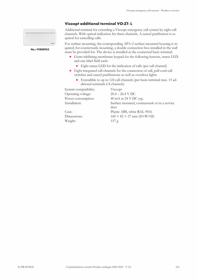
Visoopt emergency call systems · Product overview
K-HB-0053EN Communications systems Product catalogue 2020/2021 · V 2.0 163
Visoopt additional terminal VO-ZT- L
No.: FC008953
Additional terminal for extending a Visoopt emergency call system by eight callchannels. With optical indication for these channels. A cancel pushbutton is re-quired for cancelling calls.For surface mounting, the corresponding APA-2 surface-mounted housing is re-quired; for countersunk mounting, a double connection box installed in the wallmust be provided for. The device is installed at the connected basis terminal.
n Germ inhibiting membrane keypad for the following buttons, status LEDand one label field each:n Eight status LED for the indication of calls (per call channel)
n Eight integrated call channels for the connection of call, pull cord callswitches and cancel pushbuttons as well as overdoor lightsn Extendible to up to 124 call channels (per basis terminal max. 15 ad-
ditional terminals à 8 channels)System compatibility: VisooptOperating voltage: 20.4 – 26.4 V DCPower consumption: 40 mA at 24 V DC typ.Installation: Surface mounted, countersunk or in a service
ductCase: Plastic ABS, white RAL 9016Dimensions: 160 × 82 × 27 mm (H×W×D)Weight: 157 g

Visoopt emergency call systems · Product overview
164 Communications systems Product catalogue 2020/2021 · V 2.0 K-HB-0053EN
6.2 Visoopt emergency call systems and accessories
Label Type Article no.
Visoopt basis terminal VO-BT VO-BT FC008950
Visoopt additional terminal VO-ZT VO-ZT FC008951
Visoopt basis terminal VO-BT- L VO-BT-L FC008952
Visoopt additional terminal VO-ZT- L VO-ZT-L FC008953
Call pushbutton RTwith locating and reassurance light, germ inhibitingmembrane keypad
RT FC008400
Coated pull cord call switch ZTBwith locating and reassurance light, germ inhibitingmembrane keypad, intended for use in wet rooms
ZTB FC008411
Cancel pushbutton ATwith locating and reassurance light, germ inhibitingmembrane keypad
AT FC008430
Overdoor light ZSL1-SUwith red LEDs and sound generator with the opticaland acoustic indication of calls
ZSL1-SU FD805001
Surface mounted frame for SL lampsrequired for the installation of the overdoor lightsZSL1-SU
AP-ZSL FD805000
Countersunk double switchbox U2 FC88012
Cavity wall double switchbox H2 FC88013
AP case AP-2 APA-2 FC008992
Countersunk switchbox U1 FC88010
Cavity wall switchbox H1 21-2400000-01
Visoopt emergency call systems · Product overview
K-HB-0053EN Communications systems Product catalogue 2020/2021 · V 2.0 165
Label Type Article no.
AP case AP-1 APA-1 FC008991

Securwatch real-time localisation · Networked systems
166 Communications systems Product catalogue 2020/2021 · V 2.0 K-HB-0053EN
7 Securwatch real-time localisation
7.1 Networked systems· Networked systems
Reader
Long-range RF reader SLR_RFREADER_V1
No.: 21-9200000-01
With its bidirectional radio frequency antenna, the long range RF reader receivesinformation from sensor modules, patient and staff transponders and transmitsthese to a server via a TCP/IP interface.Suited for wall and ceiling mounting. Generally installed so that a comprehensiveradio coverage of the supervised area is provided for. The overlapping of the RFfields of individual readers is permissible.For surface mounting, the mounting kit SLK_MOUNTKIT_V1 as well as flat-head screws with a diameter of max. 4 mm (head diameter max. 7 mm) are re-quired.
n Maximum radius of radio coveragen Inside up to 40 metres (depending on the building)n Outside up to 500 metres (visual range)
n Power supply via PoE Plus or external power supply unitn A vandalism sensor reports the opening of the casen Multi-colour LED for status indicationn Simple familiarisation and management in the system with RFIDn Device monitoring in 30 seconds intervals
System compatibility: Securwatch SmartLibertyOperating voltage: 24 V DCWattage: 3 W at 24 V DCInterfaces:
System connection: 1 × RJ-45 socket for connection to the network(Ethernet 10/100, with simultaneous powersupply PoE Plus in accordance with IEEE802.3at)
Long-range technology: HF 868 MHz, bidirectionalRFID aerial: 13.56 MHz, passive RFID (ISO 15693 ICODE
SLI R/W)Installation: Surface mountingProtection class: IP 40 (expendable to IP 65 with the retrofit kit)Ambient temperature: -20 °C to +60 °CRelative air humidity: up to 95 % without condensationCase: Polycarbonate, halogen-free, whiteDimensions: 195 × 195 × 37 mm (H×W×D)Weight: 390 g

Securwatch real-time localisation · Networked systems
K-HB-0053EN Communications systems Product catalogue 2020/2021 · V 2.0 167
Geolocation marker PIR, LF, IR SLM_MARKER_V1
No.: 21-9200004-01
The geolocation marker enables the tracking of patient and staff transpondersand works with a combination of infrared and low frequency signals.Suitable for wall mounting. Installed at specific locations, generally in the area ofthe door. The overlapping of the RF fields of individual markers should beavoided.For surface mounting, the mounting kit SLK_MOUNTKIT_V1 as well as flat-head screws with a diameter of max. 4 mm (head diameter max. 7 mm) are re-quired.In case of power supply via the 230-VAC grid, the mounting kit SLK_MOUN-TKIT230V_V1 must be used; in case of battery operation or power supply via a24-VDC mains, mounting kit SLK_MOUNTKIT_V1 must be used.
n Thanks to the integrated motion sensor, the LF radio field is inactivewhen not required
n The maximum tracking range is:n with integrated antenna up to 5 metres (adjustable)n with connected ground loop up to 100 metres
n Power supply can be flexibly selectedn 230 VAC with mounting kit SLK_MOUNTKIT230V_V1n 24 VDC with external power supply unit and connector plug
SLM_PLUG24V_V1n Battery SLM_BATLITHIUM_V1
n A vandalism sensor reports the opening of the casen Multi-colour LED for status indicationn Simple familiarisation and management in the system with RFIDn Device monitoring in 30 seconds intervals
System compatibility: Securwatch SmartLibertyInterfaces:
Long-range technology: HF 868 MHz, bidirectionalTracking technology: LF 125 kHz, infrared (940 nm, 36 kHz) and PIRRFID aerial: 13.56 MHz, passive RFID (ISO 15693 ICODE
SLI R/W)Installation: Surface mountingProtection class: IP 40 (expendable to IP 65 with the retrofit kit)Ambient temperature: -20 °C to +60 °CRelative air humidity: up to 95 % without condensationCase: Polycarbonate, halogen-free, white (black
corners)Dimensions: 158 × 158 × 40 mm (H×W×D)Weight: 320 g

Securwatch real-time localisation · Networked systems
168 Communications systems Product catalogue 2020/2021 · V 2.0 K-HB-0053EN
Reader and accessories
Label Type Article no.
Long-range RF reader SLR_RFREADER_V1 21-9200000-01
Mounting kit for RF SLK_MOUNTKIT_V1 21-9200001-01
Case for RF reader (replacement)Cover including bottom side SLR_COVER_V1 21-9200002-01
868 MHz rod antenna for RF reader (replace-ment) SLR_RFANTENNA_V1 21-9200003-01
Geolocation marker PIR, LF, IR SLM_MARKER_V1 21-9200004-01
Mounting kit for marker 230 VAC SLK_MOUNTKIT230V_V1 21-9200005-01
Lithium battery for marker SLM_BATLITHIUM_V1 21-9200006-01
IR corner for marker (replacement) SLM_IRCORNER_V1 21-9200008-01
PIR corner for marker (replacement) SLM_PIRCORNER_V1 21-9200009-01
Plug 24 VDC for marker SLM_PLUG24V_V1 21-9200010-01
Waterproof box IP65 for marker or RF reader SLK_WATER-PROOFKIT_V1 21-9200011-01

Securwatch real-time localisation · Networked systems
K-HB-0053EN Communications systems Product catalogue 2020/2021 · V 2.0 169
Transponder
Patient transponder RED SLB_RES_BADGE_V1
No.: 21-9210000-01
The patient transponder enables mobile individuals requiring assistance to send ahelp call or service call. Disorientation alarms can be released via the badge forindividuals with the tendency to wander. The transponder can be attached to thewrist with the supplied wristband.Accessories such as the safety pendant, belt clip and disposable wristband offeradditional wearing options. The transponder is designed for use by individualsrequiring care and is intended solely for this use.
n One button on the front for mobile help callsn Two buttons on the side for mobile service callsn Multi-colour LED for status indicationn Combined tracking technology via radio and infraredn Simple familiarisation and management in the system with RFIDn Device monitoring in 30 seconds intervals
System compatibility: Securwatch SmartLibertyBattery: CR2450 (3 V DC, 500 mAh)Interfaces:
Long-range technology: HF 868 MHz, bidirectionalTracking technology: LF 125 kHz and infrared (940 nm, 36 kHz)RFID aerial: 13.56 MHz, passive RFID (ISO 15693 ICODE
SLI R/W)Protection class: IP 67w (waterproof in shower and bath)Ambient temperature: -20 °C to +60 °CCase: Latex-free plastic, blackDimensions: 50 × 40 × 16 mm (H×W×D) excl. wristbandWeight: 44 g

Securwatch real-time localisation · Networked systems
170 Communications systems Product catalogue 2020/2021 · V 2.0 K-HB-0053EN
Staff transponder with clip SLB_STA_BADGE_V1
No.: 21-9210018-01
The staff transponder with a clip is designed to look like a name plate. Thetransponder can be used to release help or aggression calls, acknowledge alarmsand accompany disoriented inhabitants. The supplied clip can be used to attachthe transponder to the outer clothing.The transponder is designed for use by staff and is intended solely for this use.
n One button at the rear for mobile help and aggression callsn One button at the rear for acknowledging callsn Multi-colour LED for status indicationn Combined tracking technology via radio and infraredn Simple familiarisation and management in the system with RFIDn Device monitoring in 30 seconds intervals
System compatibility: Securwatch SmartLibertyBattery: CR2450 (3 V DC, 500 mAh)Interfaces:
Long-range technology: HF 868 MHz, bidirectionalTracking technology: LF 125 kHz and infrared (940 nm, 36 kHz)RFID aerial: 13.56 MHz, passive RFID (ISO 15693 ICODE
SLI R/W)Alarm acknowledgement: 125 kHz transmitter with 1 m range (only active
when pressing acknowledgement button)Protection class: IP 67 (waterproof in shower and bath)Ambient temperature: -20 °C to +60 °CCase: Latex-free plastic, blackDimensions: 59 × 88 × 13 mm (H×W×D) excl. clipWeight: 56 g

Securwatch real-time localisation · Networked systems
K-HB-0053EN Communications systems Product catalogue 2020/2021 · V 2.0 171
Transponder and accessories
Label Type Article no.
Patient transponder RED with wristband SLB_RES_BADGE_V1 21-9210000-01
Cover for patient transponderRed SLB_RES_COVERRED_V1 21-9210001-01
Cover for patient transponderblue
SLB_RES_COVER-BLUE_V1 21-9210002-01
Cover for patient transponderPink SLB_RES_COVERPINK_V1 21-9210003-01
Cover for patient transponderYellow
SLB_RES_COVERYEL-LOW 21-9210004-01
Wristband with buckle (replacement) for patient transponder
SLB_RES_WRISTBAND-BUC 21-9210005-01
Wristband with holes (replacement)for patient transponder
SLB_RES_WRISTBAND-HOL 21-9210006-01
Rubber loop (replacement)for patient transponder wristband SLB_RES_RUBBERLOOP 21-9210013-01
Bottom (replacement)for patient transponder SLB_RES_BOTTOM_V1 21-9210007-01
Safety fastenerfor patient transponder SLB_RES_LOCK_V1 21-9210008-01
Safety lock keyfor patient transponder SLB_RES_LOCKKEY_V1 21-9210009-01
Disposable wristband blackfor patient transponder SLB_RES_DISPOBAND_V1 21-9210010-01
Belt clipfor patient transponder SLB_RES_BELTCLIP_V1 21-9210011-01
Pendant clipsfor patient transponder, 2 pcs. SLB_RES_PENDANTCLIP 21-9210012-01

Securwatch real-time localisation · Networked systems
172 Communications systems Product catalogue 2020/2021 · V 2.0 K-HB-0053EN
Label Type Article no.
Safety pendantfor patient transponder, requiresSLB_RES_PENDANTCLIP
SLB_RES_PENDANT_V1 21-9210014-01
Battery CR2450for patient and staff transponder CSM_BATCR2450_V1 21-9210015-01
Screw driver torx T6 SLB_RES_SCREWDRIVER 21-9210016-01
Screw set (replacement)for patient and staff transponder SLB_SCREWS_V2 21-9210017-01
Staff transponderwith clip SLB_STA_BADGE_V1 21-9210018-01
Staff transponder dummywith clip, without electronics
SLB_STA_BADGENO-ELEC 21-9210019-01
Clip (replacement)for staff transponder SLB_STA_CLIP_V1 21-9210020-01
Bottom (replacement)for staff transponder SLB_STA_BOTTOM_V1 21-9210021-01
Cover (replacement)for staff transponder SLB_STA_COVER_V1 21-9210022-01
Window (replacement)for staff transponder SLB_STA_WINDOW_V1 21-9210023-01

Securwatch real-time localisation · Networked systems
K-HB-0053EN Communications systems Product catalogue 2020/2021 · V 2.0 173
System components
System switch Securwatch L3 JL261ANo.: 21-9220100-01 Switch for set-up of an L3 network for Securwatch systems. The switch network
is required for connecting the server with network-compatible system compon-ents.A corresponding installation kit is required for installation in a network cabinet(1 height unit).
n 24 × 1 gigabit ports with PoE Plus (370 W)n 4 × SFP portsn Layer-3-switch with a routing table size of
n 2000 at IPv4n 1000 at IPv6
System compatibility: Securwatch SmartLibertyOperating voltage: 100 – 127 V AC or 200 – 240 V ACCurrent intensification: 4.9 A or 2.4 AWattage: 36.8 – 445 WPoE output: 370 WInterfaces/ports: 24 × RJ-45 sockets 10/100/1000 PoE Plus and
4 × SFPInstallation: 19" network cabinet (1 height unit)Heat dissipation: 272.2 kJ/hAmbient temperature: 0 °C to +45 °CRelative air humidity: 15 to 95 % without condensationDimensions: 43.9 × 442.5 × 304.2 mm (H×W×D)Weight: 3.9 kg

Securwatch real-time localisation · Networked systems
174 Communications systems Product catalogue 2020/2021 · V 2.0 K-HB-0053EN
System switch Securwatch L2 J9773ANo.: 21-9220101-01 Switch for set-up of an L2 network for Securwatch systems. The switch network
is required for connecting the server with network-compatible system compon-ents.A corresponding installation kit is required for installation in a network cabinet(1 height unit).
n 24 × 1 gigabit ports with PoE Plus (195 W)n 4 × SFP portsn Layer-2-switch up to 16 000 MAC address entries
System compatibility: Securwatch SmartLibertyOperating voltage: 100 – 127 V AC or 200 – 240 V ACCurrent intensification: 3.2 A or 1.6 AWattage: 25.2 – 247 WPoE output: 195 WInterfaces/ports: 24 × RJ-45 sockets 10/100/1000 PoE Plus and
4 × SFPInstallation: 19" network cabinet (1 height unit)Heat dissipation: 142.42 kJ/hAmbient temperature: 0 °C to +45 °CRelative air humidity: 15 to 95 % without condensationDimensions: 44.5 × 443.5 × 330.2 mm (H×W×D)Weight: 3.95 kg
Securwatch SmartLiberty serverNo.: Upon request Server including operating system for the operation of Securwatch SmartLiberty
systems.

Securwatch real-time localisation · Networked systems
K-HB-0053EN Communications systems Product catalogue 2020/2021 · V 2.0 175
Sensor module SLS_MODULE_V1
No.: 21-9220004-01
The sensor module can be flexibly used for a variety of functions due to thesensors and ports. Help calls can be released via the pull cord and the push but-ton. Due to the included magnetic sensor, it can also be used as a door openingsensor. And external devices can be connected to the 3.5 mm mono jack plug.Suitable for wall mounting.For surface mounting, additional flat-head screws with a diameter of max. 3 mmand a head height of max. 2.2 mm (head diameter max. 10 mm) are required. Thecorresponding holder SLS_HOLDER_V1 is supplied as standard.
n One button on the front for releasing help callsn One pull cord for releasing help callsn Magnetic sensor integrated in the devicen Digital or analogue inputn Digital outputn Multi-colour LED for status indicationn Combined tracking technology via radio and infraredn Simple familiarisation and management in the system with RFIDn Device monitoring in 30 seconds intervals
System compatibility: Securwatch SmartLibertyBattery: CR2450 (3 V DC, 500 mAh)Interfaces:
Long-range technology: HF 868 MHz, bidirectionalTracking technology: LF 125 kHz and infrared (940 nm, 36 kHz)RFID aerial: 13.56 MHz, passive RFID (ISO 15693 ICODE
SLI R/W)Protection class: IP 65 (waterproof when exposed to jets of wa-
ter)Ambient temperature: -20 °C to +60 °CPull cord: approx. 1.2 mGrip: 20 × 30 mm (D×H)Case: Latex-free plastic, blackDimensions: 100 × 90 × 22 mm (H×W×D)Weight: 200 g

Securwatch real-time localisation · Networked systems
176 Communications systems Product catalogue 2020/2021 · V 2.0 K-HB-0053EN
Replacement parts starter kit SLK_STARTERKIT_V1
No.: 21-9220018-01
Case with the most important replacement parts for Securwatch. The case con-tains various small parts and wear parts as well as case parts for the on site repairof damaged components.
n 1 × screwdriver T6 [SLB_RES_SCREWDRIVER]n 1 × SLB opening kitn 1 × SLB opening basen 1 × SLB opening tooln 5 × set of screws [SLB_SCREWS_V2]n 10 × batteries [CR2450 CSM_BATCR2450_V1]n 5 × clip [SLB_STA_CLIP_V1]n 5 × window [SLB_STA_WINDOW_V1]n 2 × cover [SLB_STA_COVER_V1]n 2 × bottom [SLB_STA_BOTTOM_V1]n 2 × wristband [SLB_RES_WRISTBANDBUC]n 2 × wristband [SLB_RES_WRISTBANDHOL]n 2 × safety fastener [SLB_RES_LOCK_V1]n 2 × keys [SLB_RES_LOCKKEY_V1]n 2 × pendant clip [SLB_RES_PENDANTCLIP]n 5 × disposable wristband [SLB_RES_DISPOBAND_V1]n 2 × belt clip [SLB_RES_BELTCLIP_V1]n 2 × safety pendant [SLB_RES_PENDANT_V1]n 2 × bottom side [SLB_RES_BOTTOM_V1]n 2 × cover [SLB_RES_COVERRED_V1]n 2 × cover [SLB_RES_COVERBLUE_V1]n 2 × cover [SLB_RES_COVERPINK_V1]n 2 × cover [SLB_RES_COVERYELLOW]
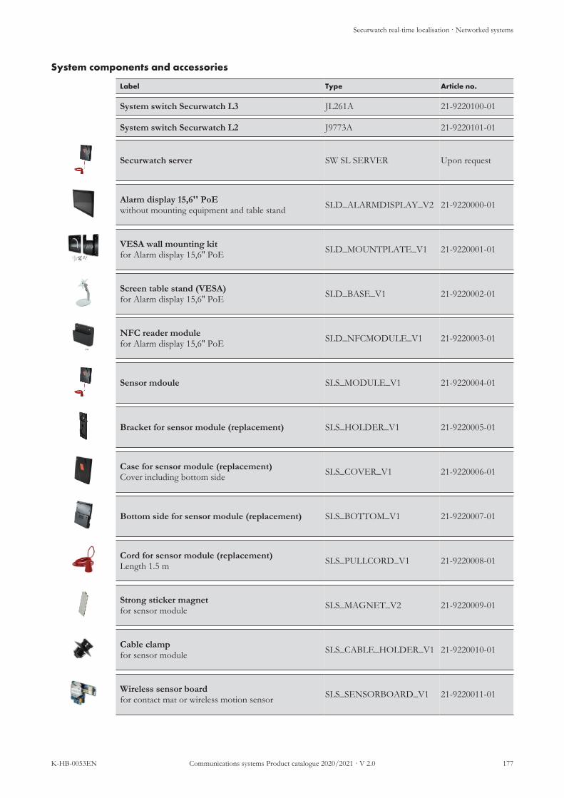
Securwatch real-time localisation · Networked systems
K-HB-0053EN Communications systems Product catalogue 2020/2021 · V 2.0 177
System components and accessories
Label Type Article no.
System switch Securwatch L3 JL261A 21-9220100-01
System switch Securwatch L2 J9773A 21-9220101-01
Securwatch server SW SL SERVER Upon request
Alarm display 15,6'' PoEwithout mounting equipment and table stand SLD_ALARMDISPLAY_V2 21-9220000-01
VESA wall mounting kitfor Alarm display 15,6'' PoE SLD_MOUNTPLATE_V1 21-9220001-01
Screen table stand (VESA)for Alarm display 15,6'' PoE SLD_BASE_V1 21-9220002-01
NFC reader modulefor Alarm display 15,6'' PoE SLD_NFCMODULE_V1 21-9220003-01
Sensor mdoule SLS_MODULE_V1 21-9220004-01
Bracket for sensor module (replacement) SLS_HOLDER_V1 21-9220005-01
Case for sensor module (replacement)Cover including bottom side SLS_COVER_V1 21-9220006-01
Bottom side for sensor module (replacement) SLS_BOTTOM_V1 21-9220007-01
Cord for sensor module (replacement)Length 1.5 m SLS_PULLCORD_V1 21-9220008-01
Strong sticker magnetfor sensor module SLS_MAGNET_V2 21-9220009-01
Cable clampfor sensor module SLS_CABLE_HOLDER_V1 21-9220010-01
Wireless sensor boardfor contact mat or wireless motion sensor SLS_SENSORBOARD_V1 21-9220011-01

Securwatch real-time localisation · Networked systems
178 Communications systems Product catalogue 2020/2021 · V 2.0 K-HB-0053EN
Label Type Article no.
Contact mat 1100 × 700 mmrequires wireless sensor board SEN_CARPET_10V1 21-9220012-01
Wireless motion sensorrequires wireless sensor board SEN_MOTION_V1 21-9220013-01
I/O module (8 in/8 out)24 VDC supply is additionally required SLI_IOMODULE_V1 21-9220014-01
PoE splittersupplies 24 VDC for I/O module PWR_24VPOE_V1 21-9220017-01
I/O module mounting bracket SLI_IOHOLDERUNI_V1 21-9220015-01
I/O module DIN SLI_IOHOLDERDIN_V1 21-9220016-01
Replacement parts starter kit SLK_STARTERKIT_V1 21-9220018-01
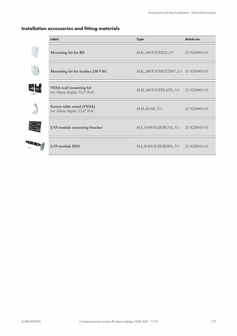
Securwatch real-time localisation · Networked systems
K-HB-0053EN Communications systems Product catalogue 2020/2021 · V 2.0 179
Installation accessories and fitting materials
Label Type Article no.
Mounting kit for RF SLK_MOUNTKIT_V1 21-9200001-01
Mounting kit for marker 230 VAC SLK_MOUNTKIT230V_V1 21-9200005-01
VESA wall mounting kitfor Alarm display 15,6'' PoE SLD_MOUNTPLATE_V1 21-9220001-01
Screen table stand (VESA)for Alarm display 15,6'' PoE SLD_BASE_V1 21-9220002-01
I/O module mounting bracket SLI_IOHOLDERUNI_V1 21-9220015-01
I/O module DIN SLI_IOHOLDERDIN_V1 21-9220016-01

Securwatch real-time localisation · Networked systems
180 Communications systems Product catalogue 2020/2021 · V 2.0 K-HB-0053EN
Replacement parts
Label Type Article no.
868 MHz rod antenna for RF reader (replace-ment) SLR_RFANTENNA_V1 21-9200003-01
Bottom (replacement)for staff transponder SLB_STA_BOTTOM_V1 21-9210021-01
Bottom (replacement)for patient transponder SLB_RES_BOTTOM_V1 21-9210007-01
Bottom side for sensor module (replacement) SLS_BOTTOM_V1 21-9220007-01
Bracket for sensor module (replacement) SLS_HOLDER_V1 21-9220005-01
Case for RF reader (replacement)Cover including bottom side SLR_COVER_V1 21-9200002-01
Case for sensor module (replacement)Cover including bottom side SLS_COVER_V1 21-9220006-01
Clip (replacement)for staff transponder SLB_STA_CLIP_V1 21-9210020-01
Cord for sensor module (replacement)Length 1.5 m SLS_PULLCORD_V1 21-9220008-01
Cover (replacement)for staff transponder SLB_STA_COVER_V1 21-9210022-01
Cover for marker (replacement) SLM_COVER_V1 21-9200007-01
IR corner for marker (replacement) SLM_IRCORNER_V1 21-9200008-01
PIR corner for marker (replacement) SLM_PIRCORNER_V1 21-9200009-01
Replacement parts starter kit SLK_STARTERKIT_V1 21-9220018-01

Securwatch real-time localisation · Networked systems
K-HB-0053EN Communications systems Product catalogue 2020/2021 · V 2.0 181
Label Type Article no.
Rubber loop (replacement)for patient transponder wristband SLB_RES_RUBBERLOOP 21-9210013-01
Screw set (replacement)for patient and staff transponder SLB_SCREWS_V2 21-9210017-01
Window (replacement)for staff transponder SLB_STA_WINDOW_V1 21-9210023-01
Wristband with buckle (replacement) for patient transponder
SLB_RES_WRISTBAND-BUC 21-9210005-01
Wristband with holes (replacement)for patient transponder
SLB_RES_WRISTBAND-HOL 21-9210006-01

Securwatch real-time localisation · Networked systems
182 Communications systems Product catalogue 2020/2021 · V 2.0 K-HB-0053EN
Accessories
Label Type Article no.
Battery CR2450for patient and staff transponder CSM_BATCR2450_V1 21-9210015-01
Belt clipfor patient transponder SLB_RES_BELTCLIP_V1 21-9210011-01
Cable clampfor sensor module SLS_CABLE_HOLDER_V1 21-9220010-01
Cover for patient transponderblue
SLB_RES_COVER-BLUE_V1 21-9210002-01
Cover for patient transponderYellow
SLB_RES_COVERYEL-LOW 21-9210004-01
Cover for patient transponderPink SLB_RES_COVERPINK_V1 21-9210003-01
Cover for patient transponderRed SLB_RES_COVERRED_V1 21-9210001-01
Disposable wristband blackfor patient transponder SLB_RES_DISPOBAND_V1 21-9210010-01
Lithium battery for marker SLM_BATLITHIUM_V1 21-9200006-01
NFC reader modulefor Alarm display 15,6'' PoE SLD_NFCMODULE_V1 21-9220003-01
Pendant clipsfor patient transponder, 2 pcs. SLB_RES_PENDANTCLIP 21-9210012-01
Plug 24 VDC for marker SLM_PLUG24V_V1 21-9200010-01
PoE splittersupplies 24 VDC for I/O module PWR_24VPOE_V1 21-9220017-01
Safety fastenerfor patient transponder SLB_RES_LOCK_V1 21-9210008-01

Securwatch real-time localisation · Networked systems
K-HB-0053EN Communications systems Product catalogue 2020/2021 · V 2.0 183
Label Type Article no.
Safety lock keyfor patient transponder SLB_RES_LOCKKEY_V1 21-9210009-01
Safety pendantfor patient transponder, requiresSLB_RES_PENDANTCLIP
SLB_RES_PENDANT_V1 21-9210014-01
Screw driver torx T6 SLB_RES_SCREWDRIVER 21-9210016-01
Strong sticker magnetfor sensor module SLS_MAGNET_V2 21-9220009-01
Waterproof box IP65 for marker or RF reader SLK_WATER-PROOFKIT_V1 21-9200011-01
Wireless sensor boardfor contact mat or wireless motion sensor SLS_SENSORBOARD_V1 21-9220011-01

Securwatch real-time localisation · Single-door-system
184 Communications systems Product catalogue 2020/2021 · V 2.0 K-HB-0053EN
7.2 Single-door-system· Single-door-system
Reader/receiver unit basic V100-001
No.: 22-4061001-01
The reader/receiver unit basic transmits the LF-ID, receives the signals of thetransponders in the physical proximity and forwards the information accordingly.A simultaneous detection of several transponders and an automatic field regula-tion is possible. The power supply unit is supplied as standard and must beordered separately.
n A detection distance radius of up to four metre can be setn Active transponder systemn Reliable three-dimensional detectionn Simultaneous detection of several transpondersn Automatic regulation of the detection fieldn Battery monitoring in the detection field: Transponder sends a notification
when the battery capacity is lower than 30 percentSystem compatibility: Securwatch ProOperating voltage: 12 – 26 V DCFrequency bands: 125 kHz/868 MHzRange: up to 4 mInputs/outputs: 2 × isolated relay outputs, with a load capacity
of 0,5 A/125 V AC and 1 A/30 V DC1 × isolated monitoring output in case of faults,with a load capacity of 0,5 A/125 V ACand1 A/30 V DC2 × optocoupler inputs and 6 × CPU outputs
Installation: Surface mountingAmbient temperature: -20 °C to +60 °CCase: ABS plastic, whiteDimensions: 138 × 178 × 31 mm (H×W×D)Weight: 500 g

Securwatch real-time localisation · Single-door-system
K-HB-0053EN Communications systems Product catalogue 2020/2021 · V 2.0 185
Dementia patient transponder V420-117
No.: DF100548
Transponder in a wristband case with wristband and patented fastener for local-ising dementia patients.
n LED for status indicationn Battery monitoring and batteryn Battery replaceable without professional assistancen Three-dimensional antenna for reliable detection, independent of the loca-
tionn Wristband fastener can be opened and closed any number of timesn Length adjustable when openn Can only be opened with the magnetic key
System compatibility: Securwatch ProBattery: CR2032, 3 VFrequency bands: 868.0 – 868.6 MHzActivation frequency: 125 kHzTransmission power 868 MHz: +5 dBProtection class: IP 67Material tape piece: PE fabric tape with PVC coating in leather
designCase dimensions: 50 × 47 × 10 mm (H×W×D)Wristband length: 270 mmWeight: 26 g
Magnetic key S730-003
No.: 22-4079002-01
Universal magnetic key for colortag fastener and wristband or ankle bandfastener. The special magnetic key is designed for opening the patented fastenersof the wristbands and colortag fasteners.
Power supply unit with connector plug V100-050
No.: 22-4069001-01
Power supply unit with connector plug 230 V – 12 VDC, 500 mA, with 130 cmcable for connection to the reader/receiver unit basic Basic V100-001.System compatibility: Securwatch ProOperating voltage: 100 – 240 VOperating frequency: 50 – 60 HzOutput voltage: 12 V DCWattage: 6 WDimensions: 24 × 33 × 46 mm (H×W×D)Ambient temperature: max. 40 °CPrimary connection: Europe PlugSecondary connection: stripped, tin-plated 1.5 m

Securwatch real-time localisation · Single-door-system
186 Communications systems Product catalogue 2020/2021 · V 2.0 K-HB-0053EN
Staff transponder V410-103
No.: 21-9110150-01
Transponder for the care staff in a case for alarm suppression when accompany-ing a dementia patient through the detection area. For safety reasons, acknow-ledgement is only possible within the detection area by simultaneously pressingthe buttons.
n Clip fastener for attaching to clothesn Acknowledgement button and alarm suppressionn Protection class IP 67n LED for status indicationn Battery monitoring and batteryn Battery replaceable without professional assistancen Three-dimensional antenna for reliable detection, independent of the loca-
tionSystem compatibility: Securwatch ProBattery: CR2032, 3 VFrequency bands: 868.0 – 868.6 MHzActivation frequency: 125 kHzTransmission power 868 MHz: +5 dBProtection class: IP 67Attachment: Clip fastenerMaterial tape piece: LeatherCase dimensions: 20.5 × 39 × 6 mm (H×W×D)Weight: 26 g
Magnet contact set S530-002No.: 21-9023201-01 Consists of two cases: The wired one contains the reed contact contact and is at-
tached to the door frame. The other one contains a magnet and is mounted dir-ectly to the door leaf.Connection cables: 6 mDiameter: 3 mm

Securwatch real-time localisation · Single-door-system
K-HB-0053EN Communications systems Product catalogue 2020/2021 · V 2.0 187
Single-door-system and accessories
Label Type Article no.
Reader/receiver unit basic V100-001 22-4061001-01
Power supply unit with connector plug V100-050 22-4069001-01
Dementia patient transponder V420-117 DF100548
Staff transponder V410-103 21-9110150-01
Universal magnetic key S730-003 22-4079002-01
Magnet contact set S530-002 21-9023201-01

Power supply · Power supplies
188 Communications systems Product catalogue 2020/2021 · V 2.0 K-HB-0053EN
8 Power supply
8.1 Power supplies· Power supplies
Power supply VDE0834 24V/10A CP10.241-M1
No.: 21-2300000-01
Power supply unit for 24 V power supply of wards and other areas requiring lowvoltage. The power supply unit is suited for use in medical facilities and complieswith the special protective measures through the galvanic isolation of the outputvoltage PELV/SELV with 2 × MOPP. Suited for top-hat rail and wall mount-ing.For surface mounting, the corresponding wall-mounted bracket ZM4.WALL orfitting bracket ZM12.SIDE is required; for top-hat rail mounting, a 35 mm DINtop-hat rail must be provided for. The fitting bracket ZM12.SIDE is suited fortop-hat rail and wall mounting.
NOTE
The power supply unit CP10.241-M1 corresponds to standard IEC60601-1 3rd Edition with regard to the electrical safety of call sys-tems and therefore complies with the safe isolation 2 × MOPP re-quired in accordance with VDE 0834:2016-06.
n Safe isolation 2 × MOPP in accordance with IEC 60601-1 3rd Editionn Thermal cut-off, overload/overvoltage and short-circuit protectionn Relay contact and LED for monitoring the output voltagen Mounting clips for 35 mm DIN rails for a simple and fast installation in-
cludedSystem compatibility: Visocall IP, Visocall Plus, Visoopt, SecurwatchInput voltage: 100 – 240 V AC (50 – 60 Hz)Output voltage: 24 – 28 V VDC, adjustable with potentiometerInput current: 2,15 A/100 V AC, 1,13 A/230 V ACOutput current: 12 – 10.3 A typ.Interfaces:
Inputs: 3 × spring-loaded terminals (N, L, PE)for wire diameters of up to 6 mm2 (single-wire)or 4 mm2 (strand)
Outputs: 5 × spring-loaded terminals (2 × pos. and 3 ×neg.)for wire diameters of up to 6 mm2 (single-wire)or 4 mm2 (strand)
Relay contact: 2 × plug-in terminalsfor wire diameters of up to 1.5 mm2
(single-wire or strand)Installation: Top-hat rail or surface mountedProtection class: IP 20Ambient temperature: -25 °C to +70 °CRelative air humidity: 5 to 95 % without condensationCase: Aluminium alloy with galvanised steelDimensions: 124 × 39 × 117 mm (H×W×D)Weight: 620 g
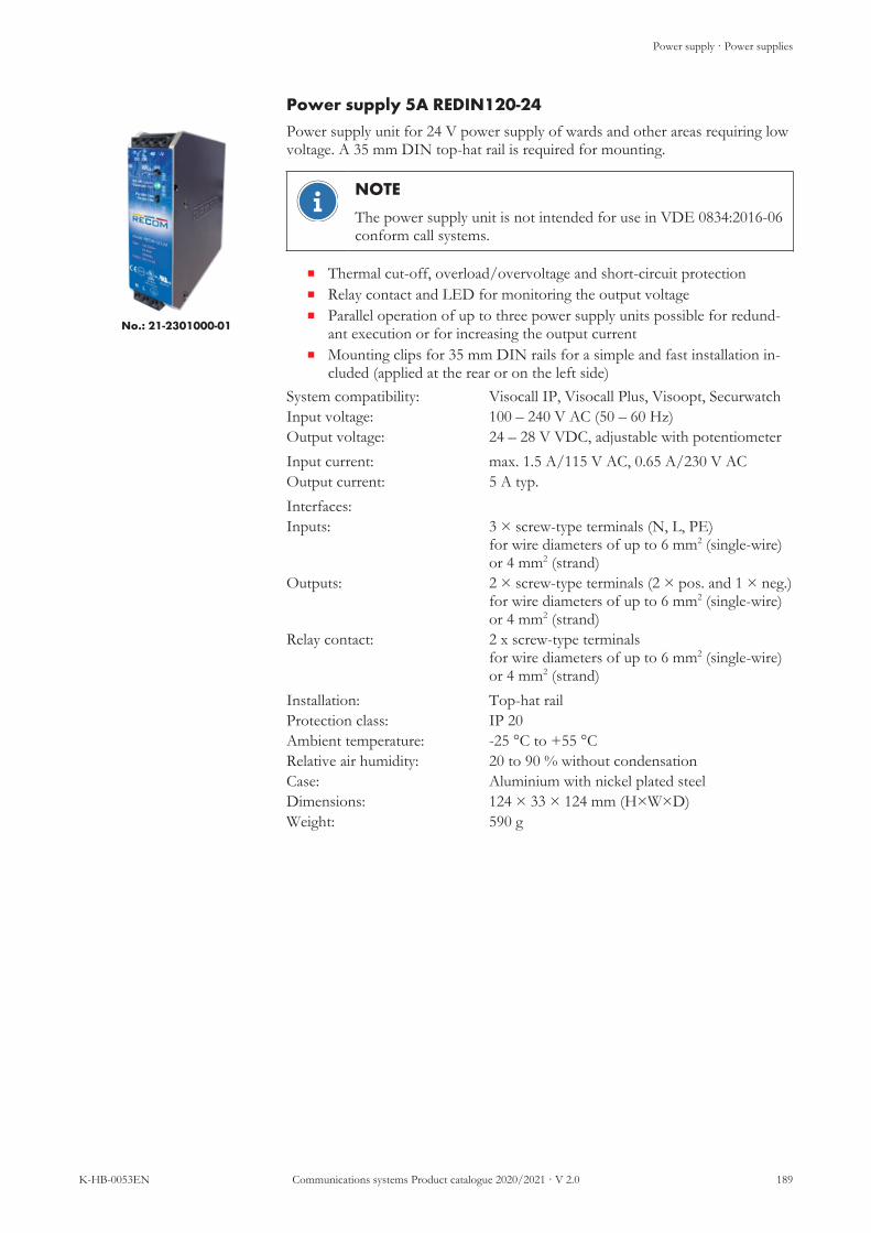
Power supply · Power supplies
K-HB-0053EN Communications systems Product catalogue 2020/2021 · V 2.0 189
Power supply 5A REDIN120-24
No.: 21-2301000-01
Power supply unit for 24 V power supply of wards and other areas requiring lowvoltage. A 35 mm DIN top-hat rail is required for mounting.
NOTE
The power supply unit is not intended for use in VDE 0834:2016-06conform call systems.
n Thermal cut-off, overload/overvoltage and short-circuit protectionn Relay contact and LED for monitoring the output voltagen Parallel operation of up to three power supply units possible for redund-
ant execution or for increasing the output currentn Mounting clips for 35 mm DIN rails for a simple and fast installation in-
cluded (applied at the rear or on the left side)System compatibility: Visocall IP, Visocall Plus, Visoopt, SecurwatchInput voltage: 100 – 240 V AC (50 – 60 Hz)Output voltage: 24 – 28 V VDC, adjustable with potentiometerInput current: max. 1.5 A/115 V AC, 0.65 A/230 V ACOutput current: 5 A typ.Interfaces:Inputs: 3 × screw-type terminals (N, L, PE)
for wire diameters of up to 6 mm2 (single-wire)or 4 mm2 (strand)
Outputs: 2 × screw-type terminals (2 × pos. and 1 × neg.)for wire diameters of up to 6 mm2 (single-wire)or 4 mm2 (strand)
Relay contact: 2 x screw-type terminalsfor wire diameters of up to 6 mm2 (single-wire)or 4 mm2 (strand)
Installation: Top-hat railProtection class: IP 20Ambient temperature: -25 °C to +55 °CRelative air humidity: 20 to 90 % without condensationCase: Aluminium with nickel plated steelDimensions: 124 × 33 × 124 mm (H×W×D)Weight: 590 g

Power supply · Power supplies
190 Communications systems Product catalogue 2020/2021 · V 2.0 K-HB-0053EN
Power supply 10A REDIN240-24
No.: 21-2301001-01
Power supply unit for 24 V power supply of wards and other areas requiring lowvoltage. A 35 mm DIN top-hat rail is required for mounting.
NOTE
The power supply unit is not intended for use in VDE 0834:2016-06conform call systems.
n Thermal cut-off, overload/overvoltage and short-circuit protectionn Relay contact and LED for monitoring the output voltagen Parallel operation of up to three power supply units possible for redund-
ant execution or for increasing the output currentn Mounting clips for 35 mm DIN rails for a simple and fast installation in-
cluded (applied at the rear or on the left side)System compatibility: Visocall IP, Visocall Plus, Visoopt, SecurwatchInput voltage: 100 – 240 V AC (50 – 60 Hz)Output voltage: 24 – 28 V VDC, adjustable with potentiometerInput current: 2.28 A/115 V AC typ., 1.13 A/230 V ACOutput current: 10 A typ.Interfaces:
Inputs: 3 × screw-type terminals (N, L, PE)for wire diameters of up to 6 mm2 (single-wire)or 4 mm2 (strand)
Outputs: 4 × screw-type terminals (2 × pos. and 2 × neg.)for wire diameters of up to 6 mm2 (single-wire)or 4 mm2 (strand)
Relay contact: 2 x screw-type terminalsfor wire diameters of up to 6 mm2 (single-wire)or 4 mm2 (strand)
Installation: Top-hat railProtection class: IP 20Ambient temperature: -25 °C to +55 °CRelative air humidity: 20 to 90 % without condensationCase: Aluminium with nickel plated steelDimensions: 124 × 46 × 124 mm (H×W×D)Weight: 810 g

Power supply · Power supplies
K-HB-0053EN Communications systems Product catalogue 2020/2021 · V 2.0 191
Power supply 20A REDIN480-24
No.: 21-2301002-01
Power supply unit for 24 V power supply of wards and other areas requiring lowvoltage. A 35 mm DIN top-hat rail is required for mounting.
NOTE
The power supply unit is not intended for use in VDE 0834:2016-06conform call systems.
n Thermal cut-off, overload/overvoltage and short-circuit protectionn Relay contact and LED for monitoring the output voltagen Parallel operation of up to three power supply units possible for redund-
ant execution or for increasing the output currentn Mounting clips for 35 mm DIN rails for a simple and fast installation in-
cluded (applied at the rear or on the left side)System compatibility: Visocall IP, Visocall Plus, Visoopt, SecurwatchInput voltage: 100 – 240 V AC (50 – 60 Hz)Output voltage: 24 – 28 V VDC, adjustable with potentiometerInput current: 4.59 A/115 V AC typ., 2.36 A/230 V AC typ.Output current: 20 A typ.Interfaces:
Inputs: 3 × screw-type terminals (N, L, PE)for wire diameters of up to 6 mm2 (single-wire)or 4 mm2 (strand)
Outputs: 4 × screw-type terminals (2 × pos. and 2 × neg.)for wire diameters of up to 6 mm2 (single-wire)or 4 mm2 (strand)
Relay contact: 2 x screw-type terminalsfor wire diameters of up to 6 mm2 (single-wire)or 4 mm2 (strand)
Installation: Top-hat railProtection class: IP 20Ambient temperature: -25 °C to +50 °CRelative air humidity: 20 to 90% without condensationCase: Aluminium with nickel plated steelDimensions: 124 × 71 × 133 mm (H×W×D)Weight: 1185 g

Power supply · Power supplies
192 Communications systems Product catalogue 2020/2021 · V 2.0 K-HB-0053EN
Power supplies and accessories
Label Type Article no.
Power supply 24 V, conforming to VDE 0834Power supply VDE0834 24V/10A CP10.241-M1 21-2300000-01
Redundany module, 24 VDC, 2 x 10 Afor redundant execution of the 24 VDC power sup-ply with automatic load distribution
YR20.246 21-2300006-01
DIMENSION 90° mounting bracketfor the side mounting of the power supply unitVDE0834 24V/10A
ZM12.SIDE 21-2300001-01
Power supply 24 VPower supply 5A (24V/120W/5A) REDIN120-24 21-2301000-01
Power supply 24 VPower supply 10A (24V/240W/10A) REDIN240-24 21-2301001-01
Power supply 24 VPower supply 20A (24V/480W/20A) REDIN480-24 21-2301002-01
Redundany module, 24 VDC, 2 x 20 Afor redundant execution of the 24 VDC power sup-ply
RM-2X20 FC008715
Input/output module IO-M-P IO-M-P 21-1023001-01

Power supply · Uninterruptible power supply
K-HB-0053EN Communications systems Product catalogue 2020/2021 · V 2.0 193
8.2 Uninterruptible power supply· Uninterruptible power supply
UPS Eaton 5PX 1500I RT2HE 5PX1500IRT
No.: FC010721 mit 4 ×No.: FC010722
Power supply for interruption-free supply of back-up power in the event ofpower failures. For use as primary side UPS for call system components.Two consumer connection cables, one RS-232 cable, one USB cable, onemounting kit for installation in 19” cabinets and one base are supplied as stand-ard. UPS electronics (1500I) can be operated alone or for extending the supplyinterruption period with up to four UPS battery modules (EBM).
n The supply interruption period depends on the connected battery mod-ules.n 1 x 1500I typ. 19 min at 50 % load or 11 min at 70 % loadn 1× 1500I and 1 × EBM typ. 90 min at 50 % load or 54 min at 70 %
loadn 1× 1500I and 4 × EBM typ. 285 min at 50 % load or 180 min load
70 % loadn Automatic battery test, deep discharge protection and automatic detection
of external battery modules (EBM)n Communication ports (USB and RS-232 cannot be used at the same time)
n 1 × USB socketn 1 × RS-232 interfacen 1 × mini terminal block for remote on/off switching
n Connection slot for a communication card (NMC Minislot, NMC Mod-Bus/JBus, MC contacts/serial)
n LC display for indication of status and measurement data of the UPSSystem compatibility: Visocall IP, Visocall Plus, SecurwatchRated power: 1500 VA / 1350 WInput voltage: 160 – 294 V AC (47 – 70 Hz)Output voltage: adjustable to:
200/208/220/230/240 V AC (50/60 Hz)Inputs/outputs: 1 × IEC C14 input (10 A)
8 × IEC C13 outputs (10 A), of which twogroups with two sockets can be remote-con-trolled
Installation: 19" network cabinet (2 height unit)Ambient temperature: 0 °C to +40 °CDimensions:
UPS electronics (1500I)Battery module (EBM)
86.2 × 441 × 522 mm (H×W×D)86.2 × 441 × 522 mm (H×W×D)
Weight:UPS electronics (1500I)Battery module (EBM)
27.6 kg (incl. battery)32.8 kg (incl. battery)

Power supply · Uninterruptible power supply
194 Communications systems Product catalogue 2020/2021 · V 2.0 K-HB-0053EN
SecoLOG IP emergency power supply SECOLOG IP EPS
No.: 23-1020001-01
Power supply for interruption-free supply of back-up power in the event ofshort-term power failures. For use on computers such as SecoLOG IP PCs orcontrol panels. Rechargeable cells are supplied as standard.
n Supply interruption period typ. 12 min at 50 % Last bzw. 7 min at 70 %Last
n Automatic battery test and deep discharge protectionn Communication ports (USB and RS-232 cannot be used at the same time)
n 1 × USB socketn 1 × RS-232 interfacen 1 × mini terminal block for remote on/off switching
n Connection slot for a communication card (network, ModBus, relay)n LC display for indication of status and measurement data of the UPS
System compatibility: Secolog IP, Visocall IP, Visocall Plus, Secur-watch
Rated power: 850 VA / 600 WInput voltage: 160 – 294 V AC (47 – 70 Hz)Output voltage: adjustable to
200/208/220/230/240 V AC (50/60 Hz)Inputs/outputs: 6 × IEC C13 outputs (10 A)Ambient temperature: 0 °C to +35°CDimensions: 230 × 150 × 345 mm (H×W×D)Weight: 10.4 kg (incl. battery)

Power supply · Uninterruptible power supply
K-HB-0053EN Communications systems Product catalogue 2020/2021 · V 2.0 195
DC UPS control unit UB20.241
No.: 21-2300004-01
The uninterruptible power supply control unit is used together with a 24 Vpower supply and batteries to bridge power failures or voltage fluctuations.Input voltage: 18 – 30 V DCOutput voltage: in mains operation like input voltage
in battery operation 22.5 V, 24 V, 25 V, 26 V(selectable)
Output current mains opera-tion:
25 A permanent, 30 A for 4 s
Output current battery opera-tion:
20 A permanent, 30 A for 4 s. at 22.5 V
Ambient temperature: -40 °C to +70 °CDimensions: 124 × 46 × 127 mm (H×W×D)Weight: 700 g
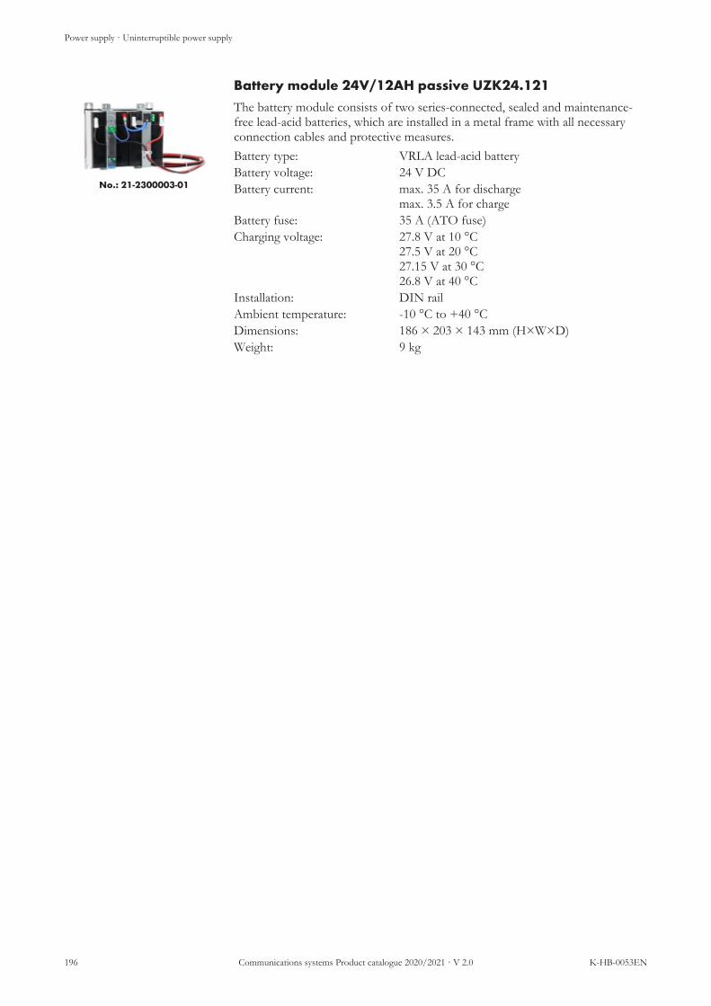
Power supply · Uninterruptible power supply
196 Communications systems Product catalogue 2020/2021 · V 2.0 K-HB-0053EN
Battery module 24V/12AH passive UZK24.121
No.: 21-2300003-01
The battery module consists of two series-connected, sealed and maintenance-free lead-acid batteries, which are installed in a metal frame with all necessaryconnection cables and protective measures.Battery type: VRLA lead-acid batteryBattery voltage: 24 V DCBattery current: max. 35 A for discharge
max. 3.5 A for chargeBattery fuse: 35 A (ATO fuse)Charging voltage: 27.8 V at 10 °C
27.5 V at 20 °C27.15 V at 30 °C26.8 V at 40 °C
Installation: DIN railAmbient temperature: -10 °C to +40 °CDimensions: 186 × 203 × 143 mm (H×W×D)Weight: 9 kg

Power supply · Uninterruptible power supply
K-HB-0053EN Communications systems Product catalogue 2020/2021 · V 2.0 197
UPS devices and accessories
Label Type Article no.
UPS Eaton 5PX 1500I RT2HEUPS electronics, incl. battery 5PX1500IRT FC010721
Replacement battery (replacement)for UPS electronics 5PX1500IRT, 1 pc., (UPS elec-tronics holds 4 batteries)
SV22-2829009-01-01 22-2829009-01
UPS Eaton 5PX EBM 48V RT2HEUPS battery module, incl. battery 5PXEBM48RT FC010722
Replacement battery (replacement)for UPS battery module 5PXEBM48RT, 1 pc., (bat-tery module hold 8 batteries)
SV22-2829010-01-01 22-2829010-01
UPS Eaton Kabel IEC320/C14-C13for the connection of a consumer device to an UPSelectronics 5PX1500IRT, cable length 1.8 m, C13connection, angled
K-USV-C14 FC010724
UPS Eaton relay management cardUSV relay module for fault analysis (e.g. connectionto IO-M-P)
RELAY-MS FC010723
USV cable Schuko-IE320/C13for the connection of UPS electronics 5PX1500IRTat a power outlet, cable length 2 m, C13 connector,lockable
K-SCHUKO-C13 FC010725
UPS cable fault analysisCable for the connection of a UPS relay module RE-LAY-MS to an input (e.g. connection to IO-M-P)
K-SUBD-STÖR FC010726
Input/output module IO-M-P IO-M-P 21-1023001-01
UPS wall-mounted bracketfor UPS Eaton 5PX 1500I RT2HE and UPS Eaton5PX EBM 48V RT2HE, dimensions: 63 × 20 × 66cm (H×W×D), capacity: 44 × 17.5 × 51cm (H×W×D)
WH-USV FC010727
UPS fault analysis relayRelay for 24 V fault analysis for ZLT USV-REL FC010728
SecoLOG IP emergency power supply incl. rechargeable cells SECOLOG IP EPS 23-1020001-01
Rechargeable cell 12 V/7 Ah (replacement)Replacement rechargeable cell for SecoLOG IPemergency power supply (UPS holds 2 rechargeablecells)
AKKU 7 HG691021

Power supply · Uninterruptible power supply
198 Communications systems Product catalogue 2020/2021 · V 2.0 K-HB-0053EN
Label Type Article no.
DC UPS control unit UB20.241 21-2300003-01
Battery module 24V/12AH UZK24.121 21-2300004-01

· Uninterruptible power supply
K-HB-0053EN Communications systems Product catalogue 2020/2021 · V 2.0 199
List of figures
Illustration 1 Connection scheme answering units .................................................................................................... 18Illustration 2 Connection scheme patient handsets ................................................................................................... 25Illustration 3 Connection scheme connection modules............................................................................................ 36Illustration 4 Connection scheme terminals ............................................................................................................... 54Illustration 5 Connection scheme intercom terminals .............................................................................................. 65Illustration 6 Connection scheme pushbuttons.......................................................................................................... 70Illustration 7 Connection scheme call indications ..................................................................................................... 93Illustration 8 Connection scheme hardware interfaces ............................................................................................. 100Illustration 9 Connection scheme radio components ............................................................................................... 113Illustration 10 Connection scheme central system components ............................................................................... 125Illustration 11 Connection scheme TV sets .................................................................................................................. 147

Index
200 Communications systems Product catalogue 2020/2021 · V 2.0 K-HB-0053EN
Product index
By article number21-1000000-01 ......................................................................13321-1000000-02 ......................................................................13321-1000000-03 ......................................................................13321-1000001-01 ......................................................................13321-1000001-02 ......................................................................13321-1000001-03 ......................................................................13321-1000100-01 ......................................................................13121-1000200-01 ......................................................................12921-1000350-01 ............................................................. 130, 14221-1000402-01 ......................................................................12621-1000500-01 ............................................................... 22, 14221-1001000-01 ................................................................. 21, 2121-1001001-01 ................................................................. 21, 2121-1001200-01 ......................................................................13421-1001201-01 ......................................................................13521-1002000-01 ............................................................... 50, 12321-1002005-01 ............................................................... 32, 14221-1002006-01 ............................................................... 32, 14221-1002030-01 .....................................................105, 142, 15121-1002030-02 .....................................................105, 142, 15121-1002031-01 ............................................................. 105, 14221-1002031-02 .....................................................105, 142, 14821-1002031-03 .....................................................105, 142, 14821-1002031-04 .....................................................105, 142, 14821-1002031-05 .....................................................105, 142, 14821-1002050-01 ............................................................... 20, 14021-1002051-01 ............................................................... 20, 14021-100220-01 ................................................................. 32, 14221-1002300-01 ............................................................... 89, 14021-1002300-02 ............................................................... 89, 14021-1002301-01 ............................................................... 89, 14021-1002500-01 .................................................. 22, 32, 62, 14221-1010000-01 ........................................................................5621-1010001-01 ........................................................................5721-1010400-01 ........................................................................6721-1010500-01 ........................................................................2021-1011000-01 ........................................................................2721-1011000-02 ........................................................................2721-1011000-03 ........................................................................2721-1011000-04 ........................................................................2721-1011002-01 ........................................................................2821-1011002-02 ........................................................................2821-1011002-03 ........................................................................2821-1011003-01 ........................................................................2921-1011003-02 ........................................................................2921-1011004-01 ........................................................................3021-1011250-01 ............................................................... 32, 14021-1011500-01 ........................................................................3821-1011501-01 ........................................................................3921-1011502-01 ........................................................................4021-1011800-01 ........................................................................4821-1013000-01 ......................................................................10621-1013001-01 .....................................................104, 148, 15121-1013002-01 ............................................................... 98, 10321-1013003-01 ............................................................... 98, 10221-1020000-01 ........................................................................5821-1020001-01 ........................................................................5921-1020002-01 ........................................................................60
21-1020300-01 ........................................................................6221-1020301-01 ........................................................................6121-1021500-01 ........................................................................4121-1021501-01 ........................................................................4221-1021800-01 ........................................................................4621-1021801-01 ........................................................................4721-1022001-01 ........................................................................7221-1022003-01 ........................................................................8421-1022004-01 ........................................................................8621-1022006-01 ........................................................................8821-1022008-01 ........................................................................7721-1022011-01 ........................................................................8121-1022012-01 ........................................................................8021-1022014-01 ........................................................................7921-1022016-01 ........................................................................7521-1022018-01 ........................................................................7421-1022020-01 ........................................................................8321-1022500-01 ........................................................................9521-1023000-01 ............................................................... 67, 10821-1023001-01 .............................................. 67, 107, 191, 19421-1023004-01 ......................................................................10921-1023005-01 ......................................................................11021-1031000-01 ........................................................................3121-1031500-01 ........................................................................4321-1031501-01 ........................................................................4521-1031502-01 ........................................................................4421-1031800-01 ........................................................................4921-1032000-01 ........................................................................7321-1032003-01 ........................................................................8521-1032004-01 ........................................................................8721-1032006-01 ........................................................................8921-1032008-01 ........................................................................7821-1032011-01 ........................................................................8221-1032016-01 ........................................................................7621-1032500-01 ........................................................................9621-2000001-01 ......................................................................15721-2000111-01 ......................................................................15421-2000121-01 ......................................................................15521-2005010-01 ......................................................................15621-2005012-01 ......................................................................15621-2005401-01-01 ................................................................15621-2005500-01-01 ................................................................15721-2005501-01-02 ................................................................15721-2010002-01 ......................................................................14821-2010003-01 ......................................................................14821-2010004-01 ......................................................................14821-2010050-01 ......................................................................14821-2010103-01 ......................................................................14821-2015000-01 ......................................................................14821-2015001-01 ......................................................................14821-2020000-01 ......................................................................15121-2020001-01 ......................................................................15121-2020002-01 ......................................................................15121-2020003-01 ......................................................................15121-2020004-01 ......................................................................15121-2020005-01 ......................................................................15121-2200000-01 ......................................................................11521-2200002-01 ......................................................................116

Index
K-HB-0053EN Communications systems Product catalogue 2020/2021 · V 2.0 201
21-2200100-01 ......................................................................11721-2200101-01 ......................................................................11721-2200102-01 ......................................................................11721-2200103-01 ......................................................................11721-2200106-01 ......................................................................12321-2200110-01 .....................................................117, 123, 14221-2200500-01 ......................................................................11721-2200550-01 ............................................................. 117, 14021-2300000-01 ......................................................................18821-2300001-01 ......................................................................19121-2300003-01 ......................................................................19521-2300004-01 ......................................................................19621-2300006-01 ......................................................................19121-2301000-01 ......................................................................18921-2301001-01 ......................................................................19021-2301002-01 ......................................................................19121-2400000-01 ................................... 51, 62, 89, 98, 139, 16321-9023201-01 ......................................................................18621-9031000-01 ............................................................... 21, 14221-9031001-01 ............................................................... 21, 14221-9110150-01 ......................................................................18621-9200000-01 ......................................................................16621-9200001-01 ............................................................. 167, 17921-9200002-01 ............................................................. 167, 18021-9200003-01 ............................................................. 167, 18021-9200004-01 ......................................................................16721-9200005-01 ............................................................. 167, 17921-9200006-01 ............................................................. 167, 18221-9200007-01 ............................................................. 167, 18021-9200008-01 ............................................................. 167, 18021-9200009-01 ............................................................. 167, 18021-9200010-01 ............................................................. 167, 18221-9200011-01 ............................................................. 167, 18221-9210000-01 ......................................................................16921-9210001-01 ............................................................. 170, 18221-9210002-01 ............................................................. 170, 18221-9210003-01 ............................................................. 170, 18221-9210004-01 ............................................................. 170, 18221-9210005-01 ............................................................. 170, 18021-9210006-01 ............................................................. 170, 18021-9210007-01 ............................................................. 170, 18021-9210008-01 ............................................................. 170, 18221-9210009-01 ............................................................. 170, 18221-9210010-01 ............................................................. 170, 18221-9210011-01 ............................................................. 170, 18221-9210012-01 ............................................................. 170, 18221-9210013-01 ............................................................. 170, 18021-9210014-01 ............................................................. 170, 18221-9210015-01 ............................................................. 170, 18221-9210016-01 ............................................................. 170, 18221-9210017-01 ............................................................. 170, 18021-9210018-01 ......................................................................17021-9210019-01 ......................................................................17021-9210020-01 ............................................................. 170, 18021-9210021-01 ............................................................. 170, 18021-9210022-01 ............................................................. 170, 18021-9210023-01 ............................................................. 170, 18021-9220000-01 ......................................................................17621-9220001-01 ............................................................. 176, 17921-9220002-01 ............................................................. 176, 17921-9220003-01 ............................................................. 176, 18221-9220004-01 ......................................................................17521-9220005-01 ............................................................. 176, 180
21-9220006-01 ............................................................. 176, 18021-9220007-01 ............................................................. 176, 18021-9220008-01 ............................................................. 176, 18021-9220009-01 ............................................................. 176, 18221-9220010-01 ............................................................. 176, 18221-9220011-01 ............................................................. 176, 18221-9220012-01 ......................................................................17621-9220013-01 ......................................................................17621-9220014-01 ......................................................................17621-9220015-01 ............................................................. 176, 17921-9220016-01 ............................................................. 176, 17921-9220017-01 ............................................................. 176, 18221-9220018-01 ............................................................. 176, 18021-9220100-01 ......................................................................17321-9220101-01 ......................................................................17422-2829009-01 ......................................................................19422-2829010-01 ......................................................................19422-4061001-01 ......................................................................18422-4069001-01 ......................................................................18522-4079002-01 ......................................................................18523-1020001-01 ......................................................................194DF010008..............................................................................127DF010009..................................................................... 127, 140DF010091-ALWL....................................................... 130, 142DF100548..............................................................................185EI931140 ........................................................................ 89, 140EI931149 ........................................................................ 98, 139EI931506-C.................................................................... 32, 140EI931506-C035 ............................................................. 32, 140EI931506-C050 ............................................................. 32, 140EI931506-C500 ............................................................. 32, 140EI931573-A ................................................................... 32, 140EI931573-A035 ............................................................. 32, 140EI931573-A050 ............................................................. 32, 140EI931573-A350 ............................................................. 32, 140EI931573-A500 ............................................................. 32, 140EI931617 ........................................................................ 62, 139EI931618 ........................................................................ 62, 139FC005205 ....................................................................... 32, 142FC006209 ....................................................................... 32, 142FC007113 ..................................................................... 148, 151FC007115 ..................................................................... 148, 151FC007942 ..............................................................................122FC007943 ..............................................................................123FC007948 ..............................................................................117FC007949 ..............................................................................117FC007957-B................................................................. 117, 140FC007957-B_27 .......................................................... 117, 140FC007972 ................................................................................89FC007973 ................................................................................89FC007974 ................................................................................89FC007975 ................................................................................89FC007996 ..................................................................... 117, 140FC008042 ..............................................................................145FC008050 ....................................................................... 21, 145FC008052 ....................................................................... 21, 145FC008400 ..............................................................................163FC008411 ..............................................................................163FC008430 ..............................................................................163FC008481 ..............................................................................121FC008715 ..............................................................................191FC008810 ................................................................................97FC008811 ................................................................................98

Index
202 Communications systems Product catalogue 2020/2021 · V 2.0 K-HB-0053EN
FC008812 ................................................................................98FC008814 ................................................................................98FC008950 ..............................................................................160FC008952 ..............................................................................162FC008991 ..................................................51, 89, 98, 139, 163FC008992 ...............................51, 98, 110, 139, 148, 151, 163FC009521 ..............................................................................156FC010003 ................................................................................20FC010009 ..............................................................................127FC010040 ................................................................................68FC010040-M.........................................................................145FC010045 ..............................................................................145FC010053 ....................................................................... 21, 145FC010054 ....................................................................... 21, 145FC010055 ..............................................................................145FC010056 ..............................................................................145FC010057 ..............................................................................145FC010058 ..............................................................................145FC010059 ..............................................................................145FC010060 ..............................................................................145FC010062 ..............................................................................145FC010063 ..............................................................................145FC010064 ....................................................................... 20, 145FC010065 ..............................................................................145FC010066 ....................................................................... 32, 145FC010067 ....................................................................... 32, 145FC010068 ..............................................................................145FC010069 ..............................................................................145FC010070 ..............................................................................145FC010071 ....................................................................... 22, 142FC010074 ....................................................................... 22, 142FC010092 ..............................................................................128FC010093 ..............................................................................130FC010190 ....................................................................... 60, 139FC010191 ....................................................................... 60, 139FC010240 ....................................................................... 32, 142FC010295 ....................................................................... 49, 142FC010350 ....................................................................... 51, 142FC010721 ..................................................................... 193, 193FC010722 ..............................................................................194FC010723 ..............................................................................194FC010724 ..............................................................................194FC010725 ..............................................................................194FC010726 ..............................................................................194FC010727 ..............................................................................194FC010728 ..............................................................................194FC017330 ....................................................................... 22, 142FC017978 ..................................................................... 117, 142FC017983 ..............................................................................117FC017984 ..............................................................................117FC017985 ..................................................................... 117, 140FC017986 ..............................................................................117FC017987 ..............................................................................117FC017988 ..............................................................................117FC017989 ..................................................................... 117, 140FC017998 ..................................................................... 123, 142FC12803--A ................................................................... 32, 142FC12803--B.................................................................... 32, 142FC12804 ......................................................................... 32, 142FC12805 ......................................................................... 32, 142FC38100 ................................................................................139FC81818 ......................................................................... 20, 140FC88010 ............................................. 51, 62, 89, 98, 139, 163
FC88013 .................................51, 51, 60, 60, 98, 98, 110, 110139, 139, 148, 148, 151, 151, 163, 163FC88018 ......................................................................... 67, 139FC88019 ......................................................................... 67, 139FC88115 ................................................................................110FC88116 ................................................................................110FD805000..............................................................................163FD805001..............................................................................163HG691021.............................................................................194MM001124 ............................................................................138MM001125 ............................................................................138MM001126 ............................................................................138MM001128 ............................................................................138MM001135 ............................................................................138MM010001 ............................................................................138MM010008 ............................................................................138MM011001 ............................................................................138MM011008 ............................................................................138ZZH0799504 ............................................................... 117, 140ZZH0799505 ............................................................... 117, 140ZZH0799506 ............................................................... 117, 140ZZH0799507 ............................................................... 117, 140ZZH0799508 ............................................................... 117, 140ZZL10737 ...................................................................... 32, 142ZZL10740 .................................................................... 117, 140

Index
K-HB-0053EN Communications systems Product catalogue 2020/2021 · V 2.0 203
By type designation
Numerical19HFL5014W/12 ................................................................1481G SFP LC LX............................................................ 130, 1421G SFP LC SX ............................................................ 130, 14221-9200010-01 ............................................................. 167, 18232HFL5014...........................................................................14843HFL5014...........................................................................14850HFL5014...........................................................................1485PX1500IRT................................................................ 193, 1935PXEBM48RT.....................................................................194
AA01C ......................................................................................122A01T-L869............................................................................117AD-DIA ......................................................................... 50, 123AK5-BT-B....................................................... 32, 32, 140, 140AK-BT-B.......................................... 32, 32, 32, 140, 140, 140AK-BT-BL-50 ............................................................... 32, 140AKKU 7 ................................................................................194AK-PAT-BL-280 .......................................................... 32, 140AK-PAT-BL-35............................................................. 32, 140AK-PAT-BL-500 .......................................................... 32, 140AK-PAT-BL-SPIRALE............................................... 32, 140APA-1 ........................................................51, 89, 98, 139, 163APA-2 .....................................51, 98, 110, 139, 148, 151, 163AP-KMT ........................................................................ 60, 139AP-ZSL..................................................................................163ARAT-P-IO............................................................................83ART-B .....................................................................................76ART-IO ...................................................................................75AT...........................................................................................163AT-B ........................................................................................78AT-IO......................................................................................77AT-IP66...................................................................................89AWG28/7 .............................................................................138AWG28/7-H ........................................................................138AWT-IO..................................................................................79
BB01C ......................................................................................123B01T-L869 ............................................................................117BLA-SM.......................................................................... 49, 142BT-B.........................................................................................31BT-IP .......................................................................................30
CCAT5......................................................................................138CAT5-IO...............................................................................138CAT5-IO-HF .......................................................................138CM-20W1-500 ......................................................................157CP10.241-M1........................................................................188CRIMP-IP .............................................................................138CRIMP-IP-B.........................................................................138CSM_BATCR2450_V1.............................................. 170, 182
DDB9-2M.......................................................................... 21, 142DB9-3M.......................................................................... 21, 142
DM1-IP ...................................................................................48DM-IO.....................................................................................46DMU-IO .................................................................................47DR-KMT........................................................................ 60, 139DSTK-W-VCIP............................................................. 51, 142
EEMOSAFE EN-70E.................................................... 22, 142
FFC88013 .......................... 51, 60, 98, 110, 139, 148, 151, 163FC88019 ......................................................................... 67, 139F-GSM-869 ...........................................................................117FH-MR ......................................................................... 127, 140F-MP-869 ..............................................................................117F-MP-ES ...................................................................... 117, 140F-PS-869................................................................................117F-PS-EK....................................................................... 117, 140F-RTS-869.............................................................................117F-SAD-869................................................................... 123, 142F-VMPS-869 .........................................................................117F-VMS-BAND-24 ...................................................... 117, 140F-VMS-BAND-27 ...................................................... 117, 140F-VMS-BOLT ............................................................. 117, 140F-VMS-ED .................................................................. 117, 140F-VMS-ERS................................................................. 117, 140F-VMS-INLAY ........................................................... 117, 140F-VMS-KOR ............................................................... 117, 140F-VMS-RKS................................................................. 117, 140F-VMUS-869 ........................................................................117F-WLS-869............................................................................117FX500 CV .............................................................................148FX500-FX850.......................................................................148FX850 ....................................................................................148F-ZS-869 ...............................................................................117F-ZS-ERS..................................................................... 117, 140
GGH-ZE-B..............................................................................110G-SWI9..................................................................................127
HH1........................................................ 51, 62, 89, 98, 139, 163HB-PAT ......................................................................... 32, 142HB-VC............................................................................ 32, 142HC-PAT ......................................................................... 32, 142HC-VC............................................................................ 32, 142HG32EE590FK...................................................................151HG32EE690DB ..................................................................151HG32EF690DB...................................................................151HG40EE590SK ...................................................................151HG43EE690DB ..................................................................151HG43EF690DB...................................................................151H-ICT-IP........................................................................ 67, 139HKL VCP ...................................................................... 32, 142HL27-VC........................................................................ 32, 142HL38-VC........................................................................ 32, 142HP2530-24-IP.......................................................................130

Index
204 Communications systems Product catalogue 2020/2021 · V 2.0 K-HB-0053EN
IICT-IP......................................................................................67IO-M ............................................................................... 67, 108IO-M-P .......................................................... 67, 107, 191, 194
JJ9773A .......................................................................... 174, 174JL261A...................................................................................173
KKH................................................................................... 32, 142KMT ........................................................................................56KMT-L ....................................................................................57K-PAT ............................................................................ 32, 142K-PAT-AS ..................................................................... 32, 142K-SCHUKO-C13 ................................................................194K-SUBD-STÖR ...................................................................194K-TVI-PHILIPS ......................................................... 105, 142K-TVI-PHILIPS-2..............................................105, 142, 148K-TVI-PHILIPS-3..............................................105, 142, 148K-TVI-PHILIPS-4..............................................105, 142, 148K-TVI-PHILIPS-5..............................................105, 142, 148K-TVI-SAMSUNG ............................................105, 142, 151K-TVI-SAMSUNG-2.........................................105, 142, 151K-USV-C14...........................................................................194
LL4-SWI9-GBIT ....................................................................126LDP........................................................................................131LM-B........................................................................................96LM-IO .....................................................................................95LS....................................................................................... 21, 21LS-TOUCH ..................................................................... 21, 21
MMC-IP ....................................................................................133MC-IP-D ...............................................................................133MC-IP-D-M..........................................................................133MC-IP-D-S............................................................................133MC-IP-M...............................................................................133MC-IP-S.................................................................................133MEDITOUCH-869.............................................................117MEDITOUCH-INTELLIFIX..........................................123MEDITOUCH-WH...........................................117, 123, 142MFC4C-CD ...................................................... 22, 32, 62, 142MFR-3700 ...................................................................... 22, 142MIC-USB ....................................................................... 22, 142MMNCS ................................................................................157MS4-I .....................................................................................106
NNTH-GFK............................................................................156
PPAT..........................................................................................27PAT-035 ..................................................................................27PAT-500 ..................................................................................27PAT-E......................................................................................28PAT-E-500..............................................................................28
PAT-E-RJ45-106....................................................................28PAT-L......................................................................................29PAT-L-500 ..............................................................................29PAT-RJ45-106 ........................................................................27PT-B.........................................................................................89PT-BI .............................................................................. 89, 140PT-IO ......................................................................................88PWR_24VPOE_V1.................................................... 176, 182
RRATB-B...................................................................................82RATB-IO ................................................................................81RAT-P-IO ...............................................................................80REDIN120-24......................................................................189REDIN240-24......................................................................190REDIN480-24......................................................................191RELAY-MS ..........................................................................194RFID-GH-APR............................................................. 62, 139RFID-GH-UPR ............................................................ 62, 139RFID-IO .................................................................................62RFID-IO-FRT........................................................................61RJ12-IP-B..............................................................................138RJ45-IP ..................................................................................138RM-2X20...............................................................................191RT...........................................................................................163RTB-B......................................................................................73RTB-IO ...................................................................................72RT-IP66...................................................................................89RTM-L869.................................................................... 117, 140
SS LTR.....................................................................................139S530-002 ................................................................................186S730-003 ................................................................................185SDI .........................................................................................134SECOLOG IP EPS.............................................................194SEN_CARPET_10V1 ........................................................176SEN_MOTION_V1 ...........................................................176SH-GTS.......................................................................... 32, 142SIC..........................................................................................135S-IP-1013...............................................................................156S-IP-16 ...................................................................................156SLB_RES_BADGE_V1.....................................................169SLB_RES_BELTCLIP_V1....................................... 170, 182SLB_RES_BOTTOM_V1 ........................................ 170, 180SLB_RES_COVERBLUE_V1................................. 170, 182SLB_RES_COVERPINK_V1 ................................. 170, 182SLB_RES_COVERRED_V1................................... 170, 182SLB_RES_COVERYELLOW................................. 170, 182SLB_RES_DISPOBAND_V1 ................................. 170, 182SLB_RES_LOCK_V1 ............................................... 170, 182SLB_RES_LOCKKEY_V1...................................... 170, 182SLB_RES_PENDANT_V1...................................... 170, 182SLB_RES_PENDANTCLIP ................................... 170, 182SLB_RES_RUBBERLOOP ..................................... 170, 180SLB_RES_SCREWDRIVER ................................... 170, 182SLB_RES_WRISTBANDBUC................................ 170, 180SLB_RES_WRISTBANDHOL ............................... 170, 180SLB_SCREWS_V2..................................................... 170, 180SLB_STA_BADGE_V1.....................................................170SLB_STA_BADGENOELEC..........................................170SLB_STA_BOTTOM_V1 ........................................ 170, 180

Index
K-HB-0053EN Communications systems Product catalogue 2020/2021 · V 2.0 205
SLB_STA_CLIP_V1.................................................. 170, 180SLB_STA_COVER_V1 ............................................ 170, 180SLB_STA_WINDOW_V1 ....................................... 170, 180SLD_ALARMDISPLAY_V2 ............................................176SLD_BASE_V1 .......................................................... 176, 179SLD_MOUNTPLATE_V1 ...................................... 176, 179SLD_NFCMODULE_V1......................................... 176, 182SLI_IOHOLDERDIN_V1 ...................................... 176, 179SLI_IOHOLDERUNI_V1....................................... 176, 179SLI_IOMODULE_V1 .......................................................176SLK_MOUNTKIT_V1............................................. 167, 179SLK_MOUNTKIT230V_V1 ................................... 167, 179SLK_STARTERKIT_V1 .......................................... 176, 180SLK_WATERPROOFKIT_V1............................... 167, 182SLM_BATLITHIUM_V1 ......................................... 167, 182SLM_COVER_V1...................................................... 167, 180SLM_IRCORNER_V1.............................................. 167, 180SLM_MARKER_V1 ...........................................................167SLM_PIRCORNER_V1 ........................................... 167, 180SLR_COVER_V1....................................................... 167, 180SLR_RFANTENNA_V1.......................................... 167, 180SLR_RFREADER_V1 .......................................................166SLS_BOTTOM_V1 ................................................... 176, 180SLS_CABLE_HOLDER_V1................................... 176, 182SLS_COVER_V1 ....................................................... 176, 180SLS_HOLDER_V1.................................................... 176, 180SLS_MAGNET_V2................................................... 176, 182SLS_MODULE_V1............................................................175SLS_PULLCORD_V1............................................... 176, 180SLS_SENSORBOARD_V1 ..................................... 176, 182SM.............................................................................................38SM1-B ......................................................................................43SM1-B-S ..................................................................................45SM2-B ......................................................................................44SM-B ........................................................................................41SMF-B......................................................................................49SM-MMC.................................................................................39SM-S.........................................................................................40SMU-B.....................................................................................42SRT-IO....................................................................................74SRV-SWITCH......................................................................128SSR-IO...................................................................................109ST-SWITCH.........................................................................129ST-TOUCH ............................................................................20ST-TOUCH-AK ........................................................... 20, 140ST-TOUCH-HK........................................................... 20, 140ST-TOUCH-STF .......................................................... 20, 140ST-TOUCH-WH ...................................................................20SV22-2829009-01-01 ...........................................................194SV22-2829010-01-01 ...........................................................194SWI9-RACK.........................................................................127SW-NT-OK ..........................................................................121SWP-IP/AK ...........................................................................68SWP-IP/AK-7.0...................................................................145SWP-IP/AM.........................................................................145SWP-IP/AS...........................................................................145SWP-IP/BMZ ......................................................................145SWP-IP/CD .................................................................. 32, 145SWP-IP/CD-E.............................................................. 32, 145SWP-IP/DESO....................................................................145SWP-IP/EDB ......................................................................145SWP-IP/ESPA.....................................................................145SWP-IP/HL7........................................................................145
SWP-IP/KNX......................................................................145SWP-IP/MMC-R.................................................................145SWP-IP/MON.....................................................................145SWP-IP/MP .........................................................................145SWP-IP/OPC.......................................................................145SWP-IP/PBF................................................................. 20, 145SWP-IP/PV ..........................................................................145SWP-IP/SLS.................................................................. 21, 145SWP-IP/SLS-E ............................................................. 21, 145SWP-IP/TK..........................................................................145SWP-IP/WEB......................................................................145SWP-IP/ZLS................................................................. 21, 145SWP-IP/ZLS-E............................................................. 21, 145
TT13SF.....................................................................................154T16SF.....................................................................................155TVI-IP ..................................................................104, 148, 151TXT..........................................................................................97TXT-2D...................................................................................98TXT-D.....................................................................................98TXT-W ....................................................................................98TXT-WH........................................................................ 98, 139
UU1 ........................................................ 51, 62, 89, 98, 139, 163U2 ..................................... 51, 60, 98, 110, 139, 148, 151, 163UB20.241...............................................................................195UF-ZS-869 ............................................................................117USV-REL ..............................................................................194UZK24.121 ...........................................................................196
VV100-001 ...............................................................................184V100-050 ...............................................................................185V410-103 ...............................................................................186V420-117 ...............................................................................185VDVI-IP......................................................................... 98, 102VO-BT...................................................................................160VO-BT-L...............................................................................162VOIP-H.......................................................................... 22, 142VR6-5.....................................................................................116VR6-5 DIN-NT ...................................................................115VR6-WALL.................................................................. 117, 142VTXT-IP........................................................................ 98, 103
WWA-500-RJ45-IP..................................................................156WALL-1120 ................................................................. 148, 151WALL-2225B .............................................................. 148, 151WH-USV...............................................................................194WL-500 ..................................................................................157
YYR20.246...............................................................................191
ZZE-B ......................................................................................110ZM12.SIDE ..........................................................................191ZRAT-B ..................................................................................87

Index
206 Communications systems Product catalogue 2020/2021 · V 2.0 K-HB-0053EN
ZRAT-IO ................................................................................86ZRTB-B...................................................................................85ZSL1-SU................................................................................163ZTB........................................................................................163ZT-B ........................................................................................60ZTB-IO ...................................................................................84ZTD-B.....................................................................................58ZTD-B-L.................................................................................59ZT-IP66...................................................................................89ZT-IP68...................................................................................89ZT-S2.............................................................................. 89, 140ZT-S2-E.......................................................................... 89, 140ZT-S4-E.......................................................................... 89, 140ZUB-ZE-B............................................................................110


EN
Subj
ect t
o te
chni
cal c
hang
es©
Sch
rack
pro
duct
ions
· K
-HB-
0053
EN
· V
2.0
· 01
.202
0
SCHRACK SECONET AGEibesbrunnergasse 18
A-1120 ViennaTel. +43 (1) 811 57
Czech Rep. · CZ-149 00 Prague 4 – Újezd. · Štítová 283 · Tel. +420 (2) 74 78 44 22Hungary · HU-1119 Budapest · Fehérvári út 89-95 · Tel. +36 (1) 464 43 00
India · IN-122102 Gurgaon, C-704A · Pioneer Urban Square, Sec-62 · Tel. +91 (124) 414 15 01Poland · PL-02-672 Warsaw · ul. Domaniewska 44a, bud. Platinium V · Tel. +48 (22) 330 06 20
Romania · RO-023961 Bucharest · Str. Mântuleasa nr. 15A et. 1, Sector 2 · Tel. +40 (372) 75 63 16Russia · RU-129626 Moscow · Ul. Staroalexejevskaja 5 · Tel. +7 (495) 510 50 15
Slovakia · SK-83527 Bratislava – Rača · Mudrochova 2 · Tel. +421 (2) 44 63 55 95Sweden · SE-126 30 Hägersten · Västberga Allé 60, Plan D · Tel. +46 (8) 680 18 60
Turkey · TR-34722 Kadıköy-İstanbul · Kasap İsmail Sk. 5/5 · Tel. +90 (216) 345 51 99