K. H. Engineer - Virginia Department of Transportation · Engineer (The opinions, ... Highway &...
26
SIDEWALK UNDERMINING STUDIES Phase I Hydrology and Maintenance Studies K. H. McGhee Research Engineer (The opinions, findings, and conclusions expressed in this report are those of the author and not necessarily those of the sponsoring agencies.) Virginia Highway & Transportation Research Council (A Cooperative Organization Sponsored Jointly by the Virginia Department of Highways & Transportation and the University of Virginia) Charlottesville, Virginia May 1975 VHTRC 75-R48
Transcript of K. H. Engineer - Virginia Department of Transportation · Engineer (The opinions, ... Highway &...
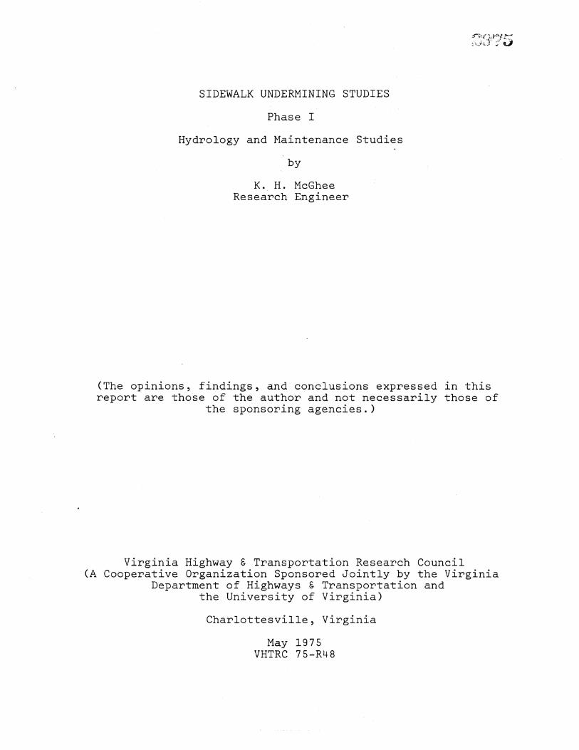
SIDEWALK UNDERMINING STUDIES
Phase I
Hydrology and Maintenance Studies
K. H. McGhee Research Engineer
(The opinions, findings, and conclusions expressed in this report are those of the author and not necessarily those of
the sponsoring agencies.)
Virginia Highway & Transportation Research Council (A Cooperative Organization Sponsored Jointly by the Virginia
Department of Highways & Transportation and the University of Virginia)
Charlottesville, Virginia
May 1975 VHTRC 75-R48


SUMMARY
Studies of the maintenance and hydrology considerations involved in a sidewalk undermining problem in the Fairfax area
are reported. Sidewalk undermining is attributed principally to a highly erodible soil found in much of the area and to the fact that current design standards and construction specifications are not adequate for sidewalk construction on such a soil.
Recommendations of the study include"
i. The use of a sidewalk replacement technique wherein the subgrade soil is protected by polyethylene sheeting and infiltrated water is carried away by a subsurface drainage system.
2. A nomograph suggested for the determination of infiltration water and subdrainage require- ments.
3. A suggestion to construct several test sections where sidewalk would be replaced on a densely graded base with a polyethylene or asphalt covering.
4. A suggestion to consider a slab removal and reuse technique.
iii


SIDEWALK UNDERMINING STUDIES
Phase I
Hydrology and Maintenance Studies
by
K H McGhee Research Engineer
INTRODUCTION
Since mid-1974 the Research Council has been working with the Fairfax Residency on a severe sidewalk maintenance problem stemming from the erodibility of certain soils found in much of Fairfax County. While there are other problems associated with sidewalk maintenance in the area, the most difficult to handle are the many cases where sidewalks have been undermined through erosion of the immediately underlying soil layer. Undermining removes the support from under the sidewalks and results in faulting of joi• and the creation of peripheral drainage and siltation problems. More importantly, the faulted joints and other sidewalk dis- tortions create hazardous conditions which need immediate repair. Due to the current policy of accepting sidewalks into the second- ary system concurrent with acceptance of the adjacent subdivision pavements, the sidewalks become a maintenance responsibility of the Highway and Transportation Department. Maintenance costs of around $200,000 to $400,000 per year are associated with the side- walk undermining problem° The situation is aggravated by the fact that undermining occurs at a faster rate than maintenance can be programmed. Thus, a recent estimate places the cost of presently needed repairs at some $2,000,000°
The attention of the. Research Council was first called to the problem through a memorandum dated March 22, 1974, from District Engineer D. B. Hope to Director of Prog•a•m Management H. G. Blundon. Specifically requested in this memorandum was the Council's as- sistance in the development of solutions applicable at the time of initial construct•on to prevent the occurrence of undermining on future sidewalks. During preliminary studies and discussions with Residency personnel it became evident, however, that any assistance with maintenance procedures, especially assistance directed at re- ducing costs, would also be welcomed. Therefore, the present report describes two test sections on which maintenance replacement procedures differing from those used by Residency personnel were employed.
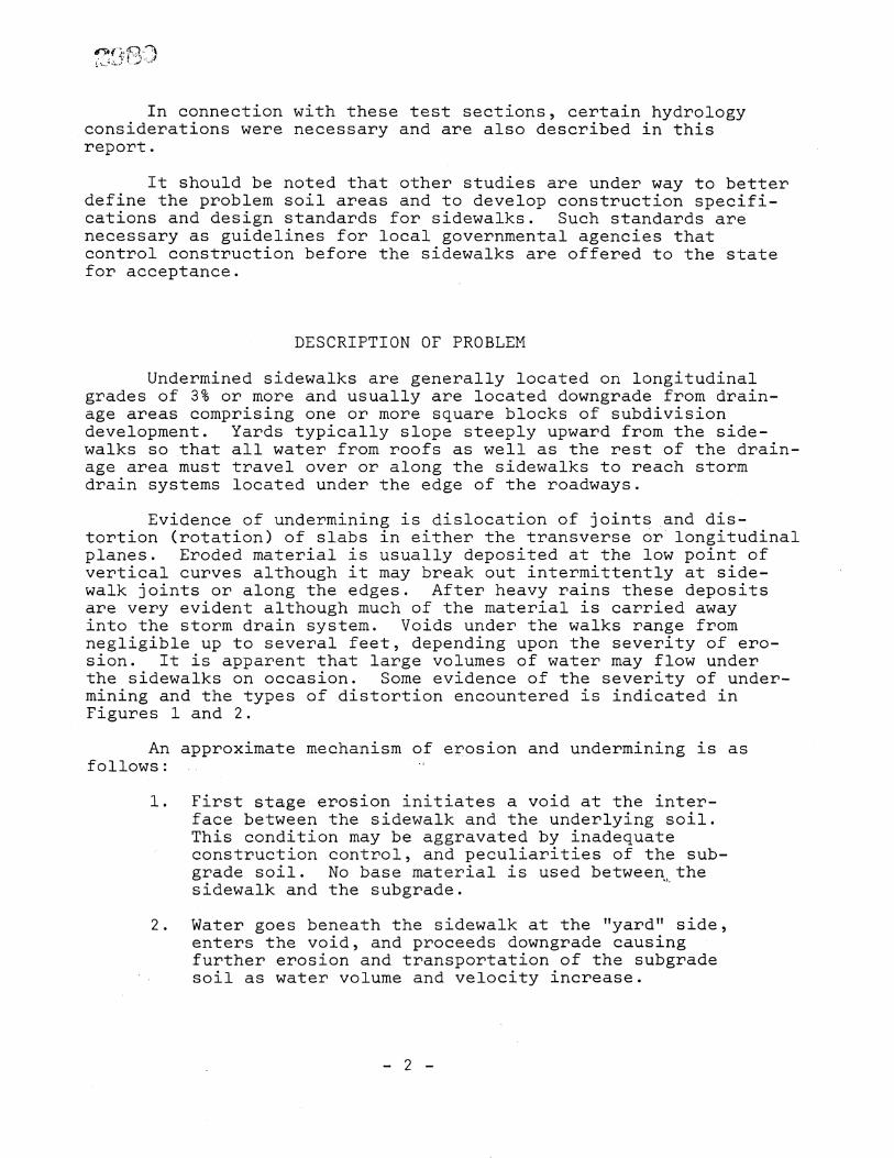
In connection with these test sections, certain hydrology considerations were necessary and are also described in this report.
It should be noted that other studies are under way to better define the problem soil areas and to develop construction specifi- cations and design standards for sidewalks. Such standards are necessary as guidelines for local governmental agencies that control construction before the sidewalks are offered to the state for acceptance.
DESCRIPTION OF PROBLEM
Undermined sidewalks are generally located on longitudinal grades of 3% or more and usually are located downgrade from drain- age areas comprising one or more square blocks of subdivision development. Yards typically slope steeply upward from the side- walks so that all water from roofs as well as the rest of the drain- age area must travel over or along the sidewalks to reach storm drain systems located under the edge of the roadways.
Evidence of undermining is dislocation of joints,•and dis- tortion (rotation) of slabs in either the transverse or• longitudinal planes. Eroded material is usually deposited at the low point of vertical curves although it may break out intermittently at side- walk joints or along the edges. After heavy rains these deposits are very evident although much of the material is carried away into the storm drain system. Voids under the walks range from negligible up to several feet, depending upon the severity of ero- sion. It is apparent that large volumes of water may flow under the sidewalks on occasion. Some evidence of the severity of under- mining and the types of• distortion encountered is indicated in Figures i and 2,
An approximate mechanism of erosion and undermining is as follows
i. First stage•:.erosion initiates a void at the inter- face between the sidewalk and the underlying soil. This condition may be aggravated by inadequate construction control, and peculiarities of the sub- grade soil. No base material is used betweeq,,the sidewalk and the subgrade.
2. Water goes beneath the sidewalk at the "yard" side, enters the void, and proceeds downgrade causing further erosion and transportation of the subgrade soil as water volume and velocity increase.
2

Figure i. Severe sidewalk undermining.
Figure 2. Sidewalk disto.rtion due to undermining.
3

3. In most cases, undermining is aggravated by the presence of a sodded utility strip from i to 12 feet (0.3 to 3.6 m) wide between the sidewalk and the roadway curb. Because of normal growth the sod in both the utility strip and the yards typically is higher in elevation than the sidewalk, and the sidewalks thus function as paved ditches to carry much of the drainage longitudinally. If voids are present under the walks, the water will flow ,uniter ..a•s well as over the concrete slabs. In an earlier study of the sidewalk maintenance problem, much of the undermining was attributed to excessive edge trimming of the walks by property owners.
(i) Such trimming, sometimes to the depth of the 4-inch (i00 ram) slabs, gives the water ready access to the subgrade soil.
4. The earlier observation that undermining is most often present where longitudinal grades are 3% or more is probably related to the fact that unless longitudinal grades are flat there will always be some longitudinal drainage, either on top of the sidewalks or beneath them. Although some of the problem sidewalks were constructed flat, many have cross-slopes of approximately 2%. When longitudinal grades exceed this 2% cross slope, the preponderance of drainage will be longitudinal.
5. One further complication to the•undermining problem is provided by water flowing downgrade on the surface of walks which have been repaired or have never been undermined until it reaches an undermined section and enters the area beneath the walks. In such cases, the volume of water contributing to the undermining can greatly exceed the runoff attributable to the property directly adjoining the walk.
METHODS OF PREVENTING UNDERMINING
Upon even scant consideration it becomes apparent that at least four actions or combinations of actions can be taken to pre- vent undermining of sidewalks built on erodible soils. These are"
i. Stop the entry of water to the areas beneath the sidewalks.
4

2o Protect the erodible soil through use of a cover material or through special handling of the sub- grade.
3o Reduce the undermining potential of infiltrated water by reducing its velocity°
4o Provide an effective means of removing infiltrated water from beneath the walks without damage to the subgrade soils°
Detailed study by others of several severe undermining situations led to the conclusion that it would be very difficult to prevent the inf•ilt•ation of surface water into the area beneath the side- walks o•± •, Thus, for maintenance purposes, both the County of Fairfax and Fairfax Residency personnel have decided that it would be•better to protect the erodible soil by the use o• aggregate base and longitudinal curtain walks under the rebuilt sidewalks and to remove infiltrated water through the use of a drainage system con- structed under the walks and draining into the existing storm sewer system. (i, 2)
A typical installation of this type is shown under construction in Figure 3 and schematically in Figure 4. Note that the drainage system is installed on the high side of the walk to intercept lat- eral drainage from yards or longitudinal drainage along the side- walk and direct it into the storm sewer system° The concrete curtain wall prevents the flow of infiltrated water laterally and directs it into the perforated plastic drain pipe° The subgrade soil to the right (Figure 4(b)) of the curtain walk is protected by a layer of densely graded crushed stoneo
Figure 3. Sidewalk replacement utilizing curtain wall and subsurface drainage°
5

pipe )
ole
.Variable Storm Sewer width
grass utility strip (a)
Drop P.C.C. Curb and Gutter Inlet
Plan View
(Not to Scale)
• 1-011
•" per ft.• 2• S ••.C.Concrete lk
• _..•• k••••• • "• C r u s h e r R u n Ag g r e g a t e
stone•kXXXX• • P.C. Concrete Curtain Well
i"0 --- i0"
(b) Section A-A (Not to Scale)
Figure •. Sidewalk reconstruction with curtain wall and drainage system. (Metric conversion 1 in.
= 25.• mm).
6

While this method of replacement has proven successful in that no subsequent undermining has been found, it is costly and questions have been raised concerning the detemmination of pipe sizes to be used on the various grades encountered in the mainte- nance program. 3) Further discussion of these questions is pre- sented below.
HYDRAULIC CONSIDERATIONS
The runoff of rainfall from dra•.n•ge calculated from the Rational Formula. •4•
areas is traditionally
Q CIA
where"
Q = Discharge (cfs)
C = Runoff coefficient
I : Average rainfall intensity (in./hr.)
A = Drainage area
For the purpose of designing sidewalk underdrains the drainage area (A) may be considered as any of the surrounding area lying at a higher elevation than the sidewalk and draining to the sidewalk without relief at some intermediate point. A simplified case is illustrated in Figure 5, where, for a sidewalk of length L with an underdrain discharging at• point C, the runoff area of depth (d) will be A dL.
For the design of pavement subdrainage systems (highly anal- ogous to the sidewalk drainage problem) Cedargren recommends using the i hour/l year frequency precipitation rate as the design pre- cipitation rate. (5) This rate is the maximum rainfall in i hour that can be expected to occur one time each year. The rate given for Virginia and recommended for this discussionis I = 1.5 in./hr. (38 mm/hr)o
The runoff coefficient is related to the slope and permeability of the drainage area and is subject to a great deal of variability. Although in most cases some water will percolate into grass covered drainage areas, it is suggested that a value of C = 1.0 be used in the present case even though a slightly excessive computed runoff may result.
7

Runoff
B •- g Sidewalk
• Utility Stmip
(a) Plan View (Not to Scale)
Percolation
(b) Cmoss (Not
FiguPe
Section
to Scale )
Runoff computat.ions. (MetPic convems•on 1
8
0.3 m).

It must be recognized that not all the runoff reaching t•e• ....
upper edge of the sidewalks will infiltrate into the area beneath the walks. Cedargren recommends that a design infiltration rate (I d) be determined by multiplying •the design precipitation rate by a coefficient between 0.50 and 0.67 for portland cement con- crete pavements. (5) The 0.67 coefficient is suggested for the determination of sidewalk infiltration so that I d 0.67 I = 0.67 x 1.5 1.0 in./hr. (25 mm/hr).
In view of the above discussion, the design discharge, Qd, from the Rational Formula with the proper dimensional constant is
CldA 1.0 x I-0 x dL dL (cfs) m•3 Qd = = = or 650 dL s 43200 43200 43200
The pipe size required to carry the design discharge with a hydraulic gradient equal to the grade of the sidewalk (g in Figure 5) can be computed from any of several pipe formulas such as those used in culvert design. Cedargren, however, has developed a nomo- graph for the determination of collector pipe diameter and spacing for use in the design of pavement subsurface drainage systems.( 5) A modification of this nomograph to accommodate the sidewalk under- drain factors is given in Figure 6.
In using the nomograph, assuming I d is always 1.0, it is necessary only to estimate the depth of the drainage area adjoining the walk and the average grade of the walk. The nomograph then may be used directly to determine the required pipe diameter (D) and the outlet spacing (L). In most practical cases the outlet spacing will be dictated by the location of storm sewer drop inlets so that the pipe size will be the only factor to be determined.
Clearly, the judgment of the engineer will be required to make use of the suggested approach in special cases, such as for extremely long segments of walk or extremely deep drainage areas. On the other hand, if the normally specified pipe is of large enough diameter, most practical cases will be handled automatically. For example, the 7-inch (178 mm) diameter pipe currently used as illustrated in Figure 4 will be adequate for most cases, some of which are given in Table i.
9

(I d) 8.0.
4.0
2.0
1.0
0.6
0.4
0,2
0.i
Cd) (L)
2000-
1000-
500-
200-
-oo 7 50-
0
D (g) FO.O01
O.OO2
0.00•
O. 01
0.02
.KEY"
EXAMPLE"
i
£igu#e 6.
design rainfall rate (in/hr)
d = depth of yard (feet)
L = distance between outlets (feet)
D = perforated pipe (corrugated) diameter (inches) fall/length
g pipe gradient (sidewalk g•ade) =
I d i 0 in/hr, d = 200 ft L i00 ft g = 0 03
Extend line from I d 1.0 in/hr through d 200 ft.
to intercept pivot line (i).
Extend line fmom pivot line to intercept pivot line (2).
(i) through L : i00 ft.
Extend line from pivot line (2) to g 0.03.
Read, D : 6" pipe required.
Nomograph for selection of perforated pipe diameters and outlet spacings. Adapted from Cedargren.(5) (Metric conversion 1 ft. = 0.3 m).
i0

Tab le 1
Typical 7-1nch Pipe Application (I d I inch)
(ft.) d (ft.)
3% i00 400
3% 200 200
4% i00 600
4% 2OO 300
6% 200 350
6% 300 200
(Metric Conversion, i ft. 0.3 m)
Upon consideration of the above factors, it was concluded that a suitable sidewalk maintenance-replacement scheme wherein the longitudinal curtain wall was eliminated could be developed with the assumption that all runoff could be handled by the under- drain system° Test sidewalk sections using this concept are discussed below.
EXPERIMENTAL MAINTENANCE INSTALLATIONS
During discussions of the sidewalk maintenance-replacement problem with Resident Engineer •N•,•, S. Roosevelt, it was recommended that several test sections usmng polyethylene sheeting to protect the erodible subgrade soil and incorporating a suitable subsurface drainage system be constructed° After several modifications to accommodate construction problemS", two test sections were con- structed as indicated in Figure 7o The actual cross section is variable in shape, depending upon the nature of the erosion channel (Figures 8 and 9). After cleaning and shaping of the subgrade soil approximately 6 inches (152 mm) of crusher run aggregate were placed in the lower portion of the trench. Polyethylene sheeting was then placed to cover the entire excavated area. A 7-inch (178 mm) diam- eter corrugated, perforated plastic pipe was laid in the trench and covered to the elevation of the bottom of the sidewalk with no. 8 stone. The no. 8 stone is open-graded to permit entry of infiltrated water to the drain pipe. After the 4-ft. (1.2 m) wide sidewalk was placed and the forms removed, the 1-ft. (0.3 m) width on either side of the walk was filled with top soil and seeded. Several of these oPerations are indicated in Figure i0o
ii

SCALE" •! _0 l!
4
in/ft 2%
P.C.C. Sidewalk
Corrugated perforated
plastic pipe
Crusher run aggregate
No. 8 Stone
Polyethylene sheeting
18"+_
6"± I
Figure 7. Cross section of experimental sidewalk installation. (Metric conversion 1 ft. 0.3 m).
Figure 8. Test site showing erosion channel.
12-
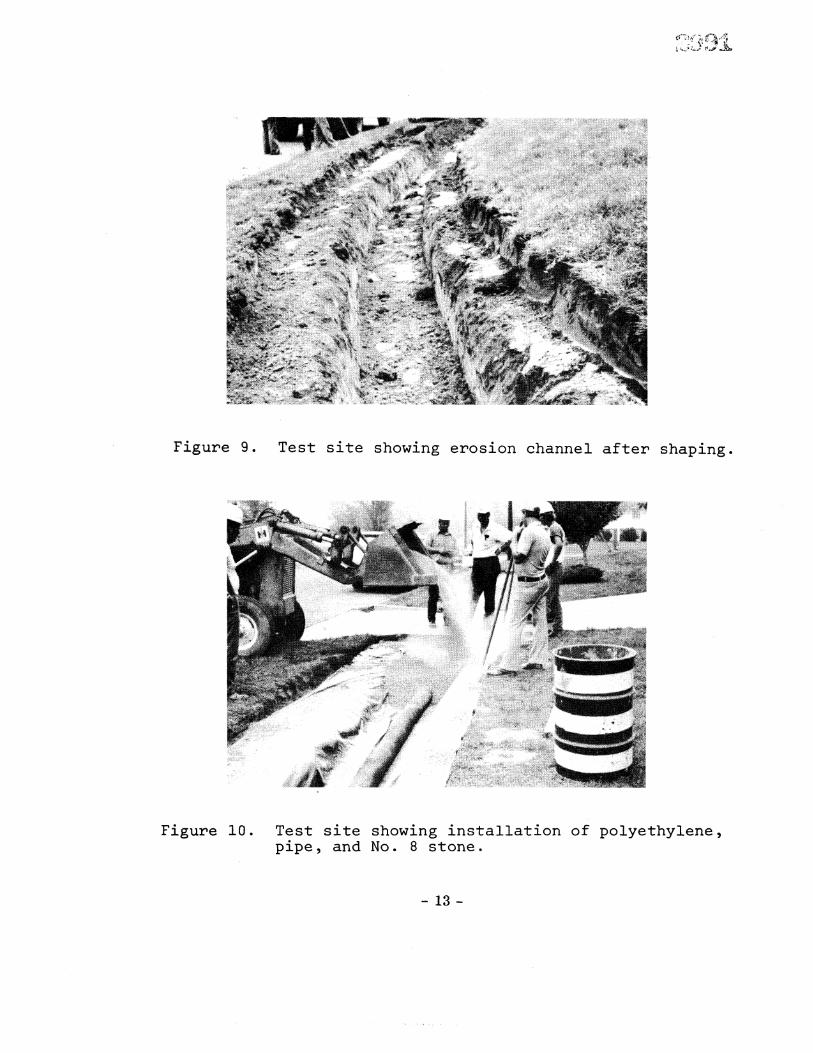
Figume 9. Test site showing erosion channel aftem shaping.
Figume i0. Test site showing installation of polyethylene, pipe, and No. 8 stone.
13-

The experimental sidewalk sections are located, as shown in Figure ii, in the Redfox subdivision just north of Route 620 near the 1-495 interchange in Fairfax County. The test sections are located on opposite sides of a vertical curve. The average grade for each section is approximately 6% and each is approxi- mately 160 ft. (48 m) long. The section on the left is tied into a previously improved section, some 70 ft. (21 m) long, where the curtain wall method was used. Therefore, the total length of drainage systems is 230 fto (69 m) and 160 ft. (48 m) for the left and right sections, respectively° The nomograph (Figure 6) dis- cussed earlier indicates that an acceptable depth of drainage area would be 250 ft. (75 m) and 400 ft. (120 m) for the left and right sections, respectively. Based on the terrain surrounding the test secti6ns, the longNr (left) section is considered barely adequate while the shorter section (right) should be more than adequately designed.
The test sections were installed in August 1974 and have been inspected periodically since that time° There is ample evidence that water is entering the drainage systems along the edges of the walks, but there is no evidence of any damage to the structure. On January 9, 1975, after reviewing the test sections several times and with agreement that the drainage systems were functioning, prop- erly, Do S. Roosevelt and the author agreed that the new system would be used in most cases where undermined sidewalk replacement was necessary, especially where storm sewer systems are available. Much of the impetus for this change was in the fact that th•re- vised system cost approximately $26 per square yard as opposed to $55 for the system containing the curtain wall. Thus, a $29, or 53%, savings was realized from use of the revised method.(6)
Finally, on March 12, 1975, after three hours of moderate•. rainfall during an extremely wet period, Ro W. Gnnn of the Research Council staff observed that the drain from the long section of walk was running approximately one-eighth full of clear water while the drain from the short section showed only a very small flow of clear water.
14-

ON asno H LE6• o•
ON •noH gE6• o• .•%uz
"ON •noH EE6• o• "a%u,•
%o•.[oa d PU3
7Z_Z
,I
SUGGESTED APPLICATIONS
The polyethylene sheeting plastic pipe method of sidewalk maintenance, while considerably simpler and less expensive than the method utilizing the curtain wall, is not universally applicable and may not be universally desirable° For example, methods in- corporating a subsurface drainage system are not practical where there are no storm drain systems. At the same time, subdrainage may not be necessary where the area draining into a segment of walk is very small. This can be seen by a detailed study of Figure 6, where it will be found that the required pipe size is negligible when the drainage area, dL, is less than about 4,000 sq. ft. (372 m
2) or 0.i acre (0.04 ha) and the grade is more than about 2%. On the other hand, it was pointed out earlier that under- mining seldom occurs where grades are less than about 3%. It would, therefore, appear reasonable to eliminate the subdrainage system when the drainage area
'is less than 0.i acre (0.04 ha). It is recognized that such a condition will .occur only occasionally as in most cases some larger drainage area upgrade will determine the effective drainage area for the section of sidewalk to be repaired. Where the subdrainage system is to be omitted, consid- eration of the alternate repair procedure described below is suggested.
DESIGN WITHOUT UNDERDRAINS
In many cases, an•ffective underdrain system cannot be provided because storm drain systems or some other drainage outlets are not conveniently located. This condition will most often occur where grades are fairly gentle such that water velocities are low enough that any undermining that occurs is caused by an extremely erodible soil or very poor construction practices. In either case, it should be possible to prevent the recurrence of undermining by the provision of reasonable protection to the subgrade soil when undermined sidewalks are replaced. One way of providing this protection is through the use of a densely-graded crushed stone covered with polyethylene sheeting or an asphalt prime coat. A suggested design for this type of replacement scheme is illustrated in Figure 12o
16
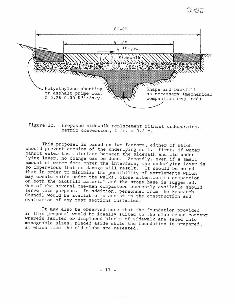
Figure 12. Proposed sidewalk replacement without underdrains. Metric conversion, i ft. 0.3 m.
This proposal is based on two factors, either of which should prevent erosion of the underlying soil. First, if water cannot enter the interface between the sidewalk•and its under- lying layer, no change can be done. Secondly, even if a small amount of water does enter the interface, the underlying layer is so impervious that no damage will result. It should be noted that in order to minimize the possibility of settlements which may create voids under the walks, close attention to compaction on both the backfill material and the stone base is suggested. One of the several one-man compactors currently available should serve this purpose. In addition, personnel from the Research Council would be available to assist in the construction and evaluation of any test sections installed.
It may also be observed here that the foundation provided in this proposal would be ideally suited to the slab reuse concept wherein faulted or displaced blocks of sidewalk are sawed into manageable sizes, placed aside while the foundation is prepared, at which time the old slabs are reseated.

RECOMMENDATIONS
In view of the fact that other studies are under way that are seeking to better define problem soil areas and to develop design standards and construction specifications for sidewalks, the several recommendations offered below should be considered only as interim solutions. Also it is noted that they apply only to sidewalk maintenance activities in areas where erodible soils are evidenced by the presence of undermining. When the problem soil areas and necessary construction controls are better understood, further recommendations for both construction and maintenance activities will be developed. For the time being, the following recommendations appear appropriate.
i. The undermined sidewalk replacement method utilizing polyethylene sheeting, an open-graded aggregate, and a subsurface drainage system should be used whenever practical.
2. The nomograph described earlied is suggested as a
means of evaluating the ability of the subsurface drainage system to handle the water infiltrating from large drainage areas. Although the judgement of the maintenance engineer must be exercised when this nomograph is used, it is believed thatthe 7-inch (178 mm) diameter plastic pipe used in the earlier test sections will carry the drainage in most practical cases.
3. For very small drainage areas where a subsurface drainage system is impractical, a replacement method utilizing a densely-gmaded stone base with a polyethylene or asphalt covering is recommended.
The construction of several test sections employing this method for larger drai•nage areas is recommended. These could be located where storm drain systems are not conveniently located. Such test sections would pro- vide an opportunity to assess this method of replacement and its performance. Satisfactory performance might suggest that subsurface drainage systems could be omitted from all future replacement activities.
4. Some consideration should be given to the slab removal and reuse methodology when an appropriate section of sidewalk is available°
18-

AC KN 0WLED G EME NT S
The author gratefully acknowledges the cooperation of Resi- dent Engineer D. S. Roosevelt, and his staff in the conduct of these studies. The efforts and interest of R. W. Gunn, materials technician supervisor, in the conduct of the field work also are
very much appreciated.
The study is under the general direction of J. H. Dillard, state highway research engineer, and is being financed from state research funds.
19


REFERENCES
i
4
Fielding, R. V., Report on Highway Research Project Sidewalks in Subdivisions, Fairfax and Prince William Counties, Virginia Department of Highways & Transportation, August 1971.
Memorandum from R. Inspection Branch, Division of Design
F. Gilbert, Assistant Chief, Public Utilities Fairfax County, to S. T. Terrett, Director, Review, Fairfax County, February 15, 1974.
Memorandum from D. E. Keith to D. B. Hope, November 15, 1971.
American Association Volume II Highway 1973.
of State Highway & Transportation Officials, Drainage Guidelines, Guideline for Hydrology,
Cedargren, Harry R., Dr..ai.nage John Wiley g Sons, New York,
of•Highway and Airfield Pavements, 1974.
Memorandum from D S. Roosevelt to 1974.
K. H. McGhee, November 6,
21-


![[FIRST DRAFT] th November 2018 Geometric loading of... · 2019-01-03 · Engineer Ahmed Hafeez Engineer Hassan Moin Engineer Waleed Arshad Engineer Shuja ur Rehman Engineer Fatima](https://static.fdocuments.net/doc/165x107/5f803af18b9e1b5ee3188a82/first-draft-th-november-geometric-loading-of-2019-01-03-engineer-ahmed.jpg)