Jurnal Teknologi Full paper - IAUNresearch.iaun.ac.ir/pd/ekianpour/pdfs/PaperM_2068.pdfJurnal...
11
71:2 (2014) 25–35 | www.jurnalteknologi.utm.my | eISSN 2180–3722 | Full paper Jurnal Teknologi Film Cooling Effectiveness in a Gas Turbine Engine: A Review Ehsan Kianpour a,b , Nor Azwadi Che Sidik b,* , Iman Golshokouh c a Faculty of Engineering, Islamic Azad University of Najaf Abad, Esfahan, Iran b Thermo-fluid Department, Faculty of Mechanical Engineering, Universiti Universiti Teknologi Malaysia, 81310 UTM Johor Bahru, Johor Malaysia c Faculty of Mechanical Engineering, Islamic Azad University of Izeh, Khuzestan, Iran *Corresponding author: [email protected] Article history Received 17 June 2013 Received in revised form 4 Sep 2014 Accepted 4 Sep 2014 Graphical abstract Abstract This study was carried out to extend database knowledge about the function of film cooling holes at the end of combustor and the inlet of turbine. Using the well-known Brayton cycle, raising the turbine inlet temperature is the key to obtain higher engine efficiency in gas turbine engines. However, high temperature of the combustor exit flow causes non-uniformities. These non- uniformities lead to the reduction of expected life of critical components. Therefore, an appropriate cooling technique should be designed to protect these parts. Film cooling is one of the most effective external cooling methods. Various film cooling techniques presented in the literature have been investigated. Moreover, challenges and future directions of film cooling techniques have been reviewed and presented in this paper. The aim of this review is to summarize recent development in research on film cooling techniques and attempt to identify some challenging issues that need to be solved for future research. Keywords: Gas turbine; film-cooling; trenched holes; shaped holes; compound holes © 2014 Penerbit UTM Press. All rights reserved. Nomenclature Area of cooling jet Cd Discharge coefficient Cp Specific heat d Trench depth D Film-cooling hole diameter g Gravitational acceleration Hin Combustor inlet height I Momentum flux ratio k Thermal conductivity L Combustor length ̇ Mass flow rate N Number of film-cooling holes p Pressure Pr Prandtl number P0 Total pressure Ps Static pressure q Heat flux Ra Rayleigh number t Time T Local temperature Tc Temperature of coolant T∞ Temperature of mainstream u Velocity in x direction ujet Velocity of cooling jet u∞ Velocity of mainstream U Dimensionless velocity in x direction v Velocity in y direction V Dimensionless velocity in y direction w Velocity in z direction W Combustor width WT Trench width x Stream-wise distance X Dimensionless stream-wise distance y Pitch-wise distance Y Dimensionless pitch-wise distance z Span-wise (vertical) distance Z Dimensionless span-wise (vertical) distance Greek Symbols Thermal diffusivity Volumetric thermal expansion coefficient Γ Diffusion coefficient Height of constriction
Transcript of Jurnal Teknologi Full paper - IAUNresearch.iaun.ac.ir/pd/ekianpour/pdfs/PaperM_2068.pdfJurnal...
71:2 (2014) 25–35 | www.jurnalteknologi.utm.my | eISSN 2180–3722 |
Full paper Jurnal
Teknologi
Film Cooling Effectiveness in a Gas Turbine Engine: A Review Ehsan Kianpoura,b, Nor Azwadi Che Sidikb,*, Iman Golshokouhc
aFaculty of Engineering, Islamic Azad University of Najaf Abad, Esfahan, Iran bThermo-fluid Department, Faculty of Mechanical Engineering, Universiti Universiti Teknologi Malaysia, 81310 UTM Johor Bahru, Johor Malaysia cFaculty of Mechanical Engineering, Islamic Azad University of Izeh, Khuzestan, Iran
*Corresponding author: [email protected] Article history
Received 17 June 2013
Received in revised form 4 Sep 2014 Accepted 4 Sep 2014
Graphical abstract
Abstract
This study was carried out to extend database knowledge about the function of film cooling holes at
the end of combustor and the inlet of turbine. Using the well-known Brayton cycle, raising the turbine inlet temperature is the key to obtain higher engine efficiency in gas turbine engines.
However, high temperature of the combustor exit flow causes non-uniformities. These non-
uniformities lead to the reduction of expected life of critical components. Therefore, an appropriate cooling technique should be designed to protect these parts. Film cooling is one of the most
effective external cooling methods. Various film cooling techniques presented in the literature have
been investigated. Moreover, challenges and future directions of film cooling techniques have been reviewed and presented in this paper. The aim of this review is to summarize recent development in
research on film cooling techniques and attempt to identify some challenging issues that need to be
solved for future research.
Keywords: Gas turbine; film-cooling; trenched holes; shaped holes; compound holes
© 2014 Penerbit UTM Press. All rights reserved.
Nomenclature
𝐴𝑗𝑒𝑡 Area of cooling jet
Cd Discharge coefficient
Cp Specific heat
d Trench depth
D Film-cooling hole diameter
g Gravitational acceleration
Hin Combustor inlet height
I Momentum flux ratio
k Thermal conductivity
L Combustor length
�̇� Mass flow rate
N Number of film-cooling holes
p Pressure
Pr Prandtl number
P0 Total pressure
Ps Static pressure
q Heat flux
Ra Rayleigh number
t Time
T Local temperature
Tc Temperature of coolant
T∞ Temperature of mainstream
u Velocity in x direction
ujet Velocity of cooling jet
u∞ Velocity of mainstream
U Dimensionless velocity in x direction
v Velocity in y direction
V Dimensionless velocity in y direction
w Velocity in z direction
W Combustor width
WT Trench width
x Stream-wise distance
X Dimensionless stream-wise distance
y Pitch-wise distance
Y Dimensionless pitch-wise distance
z Span-wise (vertical) distance
Z Dimensionless span-wise (vertical) distance
Greek Symbols
𝛼 Thermal diffusivity
𝛽 Volumetric thermal expansion coefficient
Γ Diffusion coefficient
𝛿 Height of constriction

26 Kianpour, Azwadi & Iman / Jurnal Teknologi (Sciences & Engineering) 71:2 (2014) 25–35
𝜃 Dimensionless temperature
𝜇 Dynamic viscosity
𝜈 Kinematic viscosity
𝜌 Density
𝜌𝑗𝑒𝑡 Density of cooling jet
𝜌∞ Density of mainstream
𝜏 Viscous stress
𝜎 Tangential velocity
𝜙 General variable
1.0 INTRODUCTION
Gas turbine industries are seeking for better performance and
enhancing power to weight ratio. Brayton cycle seems to be an
appropriate option for this purpose. In this cycle, the outlet
temperature of combustor or the inlet temperature of turbine must
be increased to enhance the performance of gas turbine engine
[1,2]. According to Thole and Knost [3], the operating
temperature is such above that all materials cannot resist against
this value of temperature. Also, running hot gases inside the
combustor and at the inlet of the turbine has very destructive
effects on the downstream components (Figure 1). To prevent
these problems, a number of researchers have adopted film
cooling as a solution and have attempted to increase film cooling
effectiveness to produce better conditions downstream the
combustion chamber. A cooling technique must be applied to
prevent the thermal degradation of turbine components. Primary
gas turbine engines are operated at a temperature range between
1200 ºC and 1500 ºC, but modern engines functioned at the
combustor outlet temperature between 1950 ºC and 2010 ºC [4].
However, with new schemes of cooling used since the beginning
of the 21st century, the turbine inlet temperature increased above
2000 ºC. Accordingly, restructuring the cooling holes could
improve film cooling effectiveness.
Figure 1 Schematic of annular combustor and the turbine first vane damage [2]
External and internal cooling systems are two methods of cooling
gas turbine. In the internal cooling, the compressor prepares the
coolant and it is then forced into the cooling flow circuits within
the turbine parts. In another cooling system (external cooling),
downstream parts are saved against hot gases by the injection of
the coolant from the coolant manifold. In this method, heat
transfer from hot gases to different components is quelled by the
application of coolant. The most effective method of external
cooling preservation is film-cooling. In this technique, a thin and
low temperature boundary layer is developed by cooling holes and
is attached on the protected surface (Figure 2).
Figure 2 Schematic of film cooling
Since numerous studies have been done on the effects of coolant
blowing ratio and other dynamic or thermodynamic parameters on
film cooling performance, to get an in-depth idea on restricting of
cooling holes, a broad literature survey has been conducted on
previously applied configuration of cooling holes, their
effectiveness and the increment with surface structure before
starting the restructuring procedure [5,6]. The next chapter
discusses the effects of flow characteristics variations on cooling
performance, as well as the effects of different structures of
cooling holes on film cooling effectiveness.
2.0 TRADITIONAL COOLING HOLES
Cylindrical cooling holes are a common form of cooling holes. As
illustrated in Figure 3, in this type of cooling holes, the coolant
runs through the holes and spreads into the main flow with
stream-wise angle of α from the horizontal surface. The change of
geometrical parameters of such holes is a topic that has interested
researchers for many years.
Figure 3 A schematic view of traditional cooling holes
Scheepers and Morris [7] conducted an experimental study to
investigate the heat transfer for the inlet of injection holes within a
turbine blade cooling passage. To validate the experimental
results, they simulated a CFD model with a RNG k−ε turbulence
model. The results indicated that at higher suction rate, the
quantity of heat efficiency increased with the observed extraction
degree of 150 was less than ninety- degrees extraction hole. At
suction ratio of 5, a 45 percent decrease in increment was
observed near the hole, while 25 percent decrement was observed
at SR=2.5.
Harrington et al. [8] presented a simulated flat plate. The
research was a computational and experimental one aimed at
investigating a full coverage of adiabatic film cooling
effectiveness. The focus of the findings was on the effects of ten
rows of normal short cooling holes with a length of l/D = 1.0 at
large density coolant jets and high mainstream turbulence
intensity. The test results indicated that considering the blowing
ratio, the maximum adiabatic film cooling effectiveness was
attained near the area, which covered four to eight rows of cooling

27 Kianpour, Azwadi & Iman / Jurnal Teknologi (Sciences & Engineering) 71:2 (2014) 25–35
holes. Furthermore, the interaction of injected flows sprayed from
the cooling rows limits the maximum effectiveness. On the other
hand, film cooling effectiveness on the curved surface was
investigated numerically by Koc et al. [9]. They highlighted that
the curvature of the surface and the blowing ratio affect the film
cooling effectiveness.
Yuzhen et al. [10] detected the effectiveness of film cooling
of three various multi-hole designs. In the research, they
examined the effects of spacing between cooling row, span-wise
hole pitch and the hole inclination angle. The results showed that
the row spacing ratio affects the film cooling performance. Also,
better adiabatic cooling performance is achieved using a smaller
pitch, especially for the multi-hole patterns. Ai and Fletcher [11],
Cun-liang et al. [12] and Jun Yu and Shun [13] studied the similar
case and determined that the effectiveness at locations close to the
exit of jets for wide hole spacing is slightly higher than for small
hole spacing. Meanwhile, the small hole spacing performed better
than wide hole spacing at downstream locations due to the
interaction of neighboring jets.
Figure 4 Schematic of film cooling
Abdullah and Funazaki [14] studied the effects of different hole
angles. They studied four rows of different inclined holes with
two different angles of 20 degrees and 35 degrees. They prepared
contours which showed the distribution of laterally averaged film
cooling effectiveness and film cooling performance at x/D equal
to 3, 13, 23 and 33. The results showed that at a higher blowing
ratio (BR = 3.0 and 4.0), the interaction between the neighboring
secondary air led to a full coverage film cooling effectiveness
downstream of the fourth row, which was confirmed by the
temperature field captured at x/D = 33 and BR=4.0. The results
also showed that more cooling effectiveness was achieved at a
shallow hole angle of α=20 degrees, especially at higher blowing
ratios compared to a baseline case with a hole angle of α=35
degrees. Sarkar and Bose [15] displayed that the usage of cooling
holes with elevated injection angles developed turbulence, and
higher turbulence led to the reduction of cooling performance.
Furthermore, Nasir et al. [16], Shine et al. [17] and Hale et al.
[18] simulated a flat plate with cylindrical cooling holes to study
the effects of injection angle on the effectiveness of film cooling.
They highlighted that lower stream-wise injection angles perform
better by producing a higher film cooling effectiveness.
The effects of different imperfection on film cooling and
arrangements of small holes on the jets cross flow were studied by
Jovanovic et al. [19,20] with the application of PIV and LCT
techniques. The results showed that at moderate velocity ratios,
the effectiveness of inner-torus decreased significantly and
narrowed the cooled area. At larger velocity ratios, an influence of
the inner-torus almost vanished. The imperfection located 2.5
diameters inside the hole did not have any significant influence on
the film cooling effectiveness. The free stream turbulence was
changed by means of using static grid. The turbulence intensity
was increased from 1% to 7%. The adiabatic effectiveness was
weakly affected by the turbulence intensity. Only in the vicinity of
the maximum effectiveness for the inner-torus, the effectiveness
was reduced for about 10%.
Multiple jets placed inside cross flow were used by Peterson
and Plesniak [21] to analyze the effects of velocity. They
investigated the effects of plenum flow direction, injection angle,
as well as blowing ratio. Consistent with the research by Plesniak
[22], the findings indicated that a light and less integrated counter-
rotating vortex pair (CRVP) is developed because of the vortices
spawn inside injection hole and opposite rotation direction, which
is opposite to the CRVP rotational sense with the application of
the counter-flow plenum. Compared to counter flow case, co-flow
plenum increased the trajectory and reduced span-wise injection.
Furthermore, Nakabe et al. [23] debated that jet impingement is
effective for heat transfer augmentation even in the case with
cross flow.
Hale et al. [24] measured the effectiveness of surface
adiabatic film cooling adjacent to cooling holes. They studied an
individual short holes row and narrow plenum. They noticed
different kinds of l/D ratios, injection angles, co-flow and counter-
flow plenum feed configurations (Figure 5). The findings showed
that short injection holes increased the film cooling and developed
wide cold region downstream of the cooling holes. Their findings
were identical with those of Burd and Simon’s [25], as the
relevance of the length of injection hole to effectiveness of film
cooling could be well understood. In another study, Azzi and
Jurban [26] forecasted the film cooling thermal fields for a
simulated cylindrical cooling row with the following ratios:
extended range of length to diameter = 1.75/8, and fixed pitch to
diameter = 3.0. The inclination angle was 35 degrees and the film
hole was 12.7 mm in diameter. Another finding by Bernsdorf et
al., [27], Yong-gang and Qiang [28] and Jumper [29] showed that
in short cooling injection holes, effectiveness of film cooling is
related to the injection hole length and angle.
Figure 5 Schematic of adiabatic test section and plenum [24]
In 2012, Saumweber and Schulz [30] stated that an increase of the
length of a cylindrical hole in principle, favorably affects cooling
effectiveness at plenum conditions at the hole entrance. The
experimental results collected by Mohammed and Salman [31]
indicated that the ratio of the axial length (L) to the diameter (D)
also has an effect on the average heat transfer rate at same
conditions.
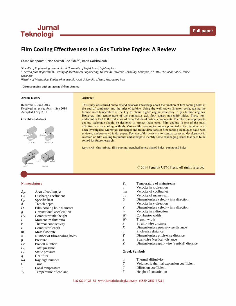
Nemdili et al. [32] conducted a numerical study to determine
the interaction of the jet cross flow and the use of imperfection
within the turbine blade cooling holes (Figure 6). The results
declared that by using imperfection inside the injection hole, the
film cooling performance reduces dramatically, whereas the rate
of velocity increases. In addition, the results found that cooling
performance is reduced dramatically when 50 percent of the
injection hole is blocked, and this phenomenon affects the turbine
blade protection intensively.
28 Kianpour, Azwadi & Iman / Jurnal Teknologi (Sciences & Engineering) 71:2 (2014) 25–35
Figure 6 The geometries of the holes (a) hole and (b) Inner torus hole [32]
Li et al. [33] and Mee et al. [34] studied the effects of distance
between two adjacent holes and suction surface of blade on heat
transfer. When an elevated distance is seen between two adjacent
cooling holes, a cooling film is found among the jet orifices. Also,
when the distance between two adjacent holes is small, the jet
orifice cooling is better than jet orifice.
Using the application of LCT technique, Nasir et al. [35]
investigated the effects of separate shaped tabs with a variety of
orientations on the film cooling performance from one cylindrical
holes row. The results showed that the upward oriented tabs are
ineffectual and reduced the film cooling performance. Using
horizontal and downward oriented tabs increased heat transfer
coefficient, but the increased value of film cooling effectiveness is
higher than heat transfer enhancement.
By using the large scale and low speed experiments,
Rowbury et al. [36,37] determined the effects of flow interaction
under the annular cascade application. They investigated the
effects of hole geometry on discharge coefficient of coolant. The
results declared that near the end of injection hole with external
cross flow, the static pressure loss relative to the assumed value
led to the discharge coefficient enhancement.
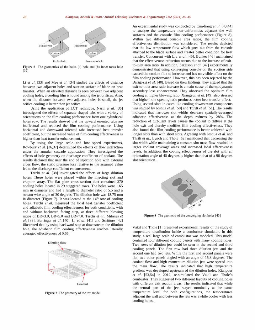
Tarchi et al. [38] investigated the effects of large dilution
holes. These holes were placed within the injecting slot and
eruption array. The flat plate cross section duct contained 270
cooling holes located in 29 staggered rows. The holes were 1.65
mm in diameter and had a length to diameter ratio of 5.5 and a
stream-wise angle of 30 degrees. The dilution hole was 18.75 mm
in diameter (Figure 7). It was located at the 14th row of cooling
holes. Tarchi et al. measured the local heat transfer coefficient
and adiabatic film cooling effectiveness for both conditions, with
and without backward facing step, at three different blowing
ratios of BR=3.0, BR=5.0 and BR=7.0. Tarchi et al., Milanes et
al. [39], Barringer et al. [40], Li et al. [41] and Scrittore [42]
illustrated that by using backward step at downstream the dilution
hole, the adiabatic film cooling effectiveness reaches laterally
averaged effectiveness of 0.65.
Figure 7 The geometry of the test model
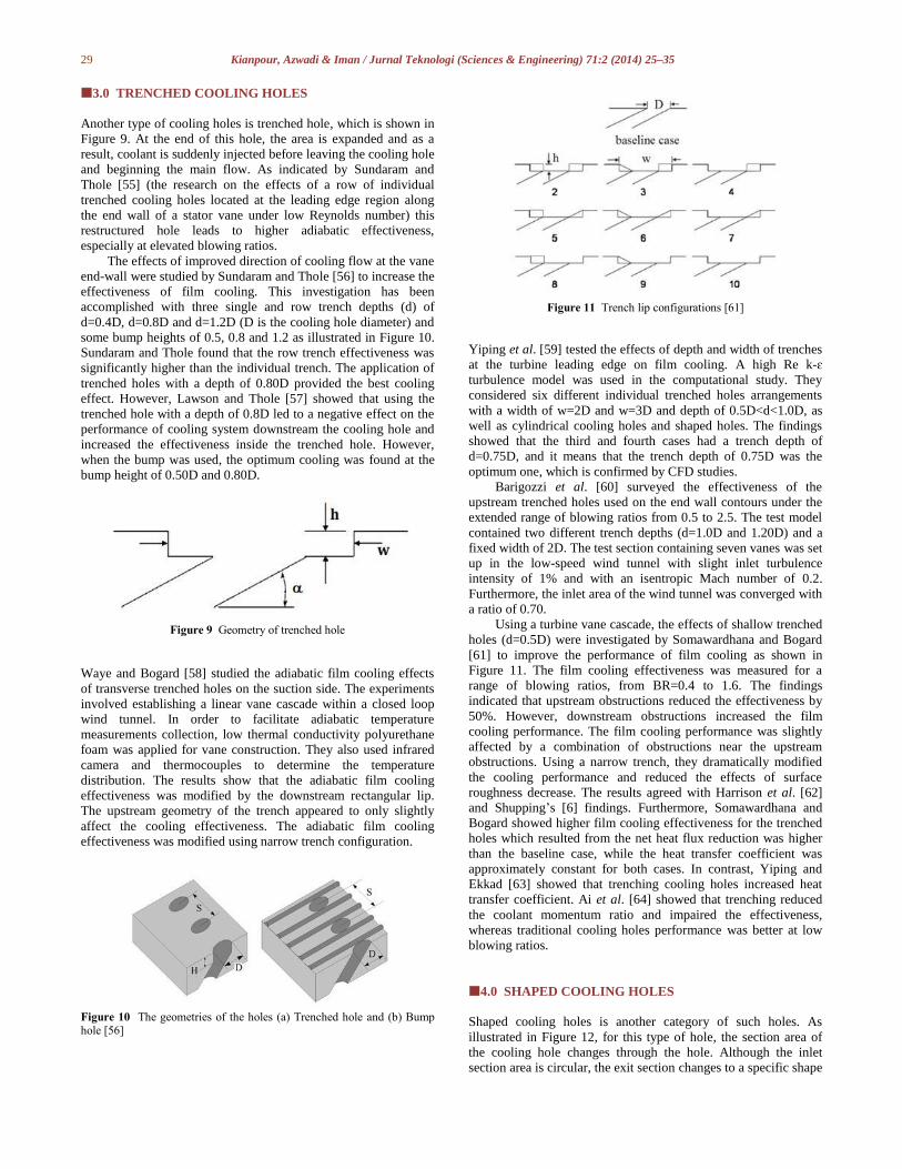
An experimental study was conducted by Cun-liang et al. [43,44]
to analyze the temperature non-uniformities adjacent the wall
surfaces and the console film cooling performance (Figure 8).
Within two different console area ratios, the film cooling
effectiveness distribution was considered. The results depicted
that the low temperature flow which goes out from the console
attached to the blade surface and creates better condition for heat
transfer. Concurrent with Liu et al. [45], Bunker [46] maintained
that the effectiveness reduction occurs due to the increase of exit-
to-inlet area ratio. In addition, Sargison et al. [47] experimentally
demonstrated that using converging console on the suction side
caused the coolant flux to increase and has no visible effect on the
film cooling performance. However, this has been rejected by the
Barigozzi et al. [48]. Based on their findings, they argued that the
exit-to-inlet area ratio increase is a main cause of thermodynamic
secondary loss enhancement. They observed the optimum film
cooling at higher blowing ratio. Xiangyun et al. [49] also stressed
that higher hole-opening ratio produces better heat transfer effect.
Using several slots in cases like cooling downstream components
was studied by Joshua et al. [50] and Thrift et al. [51]. The results
indicated that narrower slot widths decrease spatially-averaged
adiabatic effectiveness as the depth reduces by 28%. The
reduction of turbulent levels causes the coolant to diffuse at the
hole exit and thereby modifies film cooling effectiveness. They
also found that film cooling performance is better achieved with
longer slots than with short slots. Agreeing with Joshua et al. and
Thrift et al., Lynch and Thole [52] mentioned that decreasing the
slot width while maintaining a constant slot mass flow resulted in
larger coolant coverage areas and increased local effectiveness
levels. In addition, the cooling effectiveness of the slot with an
orientation angle of 45 degrees is higher than that of a 90 degrees
slot orientation.
Figure 8 The geometry of the converging slot holes [43]
Vakil and Thole [1] presented experimental results of the study of
temperature distribution inside a combustor simulator. In this
study, a real large scale of combustor was modeled. This model
contained four different cooling panels with many cooling holes.
Two rows of dilution jets could be seen in the second and third
cooling panels. The first row had three dilution jets and the
second one had two jets. While the first and second panels were
flat, two other panels angled with an angle of 15.8 degrees. The
coolant flow and high momentum dilution jets were spread into
the main flow. The results indicated that high temperature
gradient was developed upstream of the dilution holes. Kianpour
et al. [53,54] in 2012, re-simulated the Vakil and Thole’s
combustor. They suggested two different layouts of cooling holes
with different exit section areas. The results indicated that while
the central part of the jets stayed nominally at the same
temperature level for both configurations, the temperatures
adjacent the wall and between the jets was awhile cooler with less
cooling holes.
29 Kianpour, Azwadi & Iman / Jurnal Teknologi (Sciences & Engineering) 71:2 (2014) 25–35
3.0 TRENCHED COOLING HOLES
Another type of cooling holes is trenched hole, which is shown in
Figure 9. At the end of this hole, the area is expanded and as a
result, coolant is suddenly injected before leaving the cooling hole
and beginning the main flow. As indicated by Sundaram and
Thole [55] (the research on the effects of a row of individual
trenched cooling holes located at the leading edge region along
the end wall of a stator vane under low Reynolds number) this
restructured hole leads to higher adiabatic effectiveness,
especially at elevated blowing ratios.
The effects of improved direction of cooling flow at the vane
end-wall were studied by Sundaram and Thole [56] to increase the
effectiveness of film cooling. This investigation has been
accomplished with three single and row trench depths (d) of
d=0.4D, d=0.8D and d=1.2D (D is the cooling hole diameter) and
some bump heights of 0.5, 0.8 and 1.2 as illustrated in Figure 10.
Sundaram and Thole found that the row trench effectiveness was
significantly higher than the individual trench. The application of
trenched holes with a depth of 0.80D provided the best cooling
effect. However, Lawson and Thole [57] showed that using the
trenched hole with a depth of 0.8D led to a negative effect on the
performance of cooling system downstream the cooling hole and
increased the effectiveness inside the trenched hole. However,
when the bump was used, the optimum cooling was found at the
bump height of 0.50D and 0.80D.
Figure 9 Geometry of trenched hole
Waye and Bogard [58] studied the adiabatic film cooling effects
of transverse trenched holes on the suction side. The experiments
involved establishing a linear vane cascade within a closed loop
wind tunnel. In order to facilitate adiabatic temperature
measurements collection, low thermal conductivity polyurethane
foam was applied for vane construction. They also used infrared
camera and thermocouples to determine the temperature
distribution. The results show that the adiabatic film cooling
effectiveness was modified by the downstream rectangular lip.
The upstream geometry of the trench appeared to only slightly
affect the cooling effectiveness. The adiabatic film cooling
effectiveness was modified using narrow trench configuration.
Figure 10 The geometries of the holes (a) Trenched hole and (b) Bump hole [56]
Figure 11 Trench lip configurations [61]
Yiping et al. [59] tested the effects of depth and width of trenches
at the turbine leading edge on film cooling. A high Re k-ɛ
turbulence model was used in the computational study. They
considered six different individual trenched holes arrangements
with a width of w=2D and w=3D and depth of 0.5D<d<1.0D, as
well as cylindrical cooling holes and shaped holes. The findings
showed that the third and fourth cases had a trench depth of
d=0.75D, and it means that the trench depth of 0.75D was the
optimum one, which is confirmed by CFD studies.
Barigozzi et al. [60] surveyed the effectiveness of the
upstream trenched holes used on the end wall contours under the
extended range of blowing ratios from 0.5 to 2.5. The test model
contained two different trench depths (d=1.0D and 1.20D) and a
fixed width of 2D. The test section containing seven vanes was set
up in the low-speed wind tunnel with slight inlet turbulence
intensity of 1% and with an isentropic Mach number of 0.2.
Furthermore, the inlet area of the wind tunnel was converged with
a ratio of 0.70.
Using a turbine vane cascade, the effects of shallow trenched
holes (d=0.5D) were investigated by Somawardhana and Bogard
[61] to improve the performance of film cooling as shown in
Figure 11. The film cooling effectiveness was measured for a
range of blowing ratios, from BR=0.4 to 1.6. The findings
indicated that upstream obstructions reduced the effectiveness by
50%. However, downstream obstructions increased the film
cooling performance. The film cooling performance was slightly
affected by a combination of obstructions near the upstream
obstructions. Using a narrow trench, they dramatically modified
the cooling performance and reduced the effects of surface
roughness decrease. The results agreed with Harrison et al. [62]
and Shupping’s [6] findings. Furthermore, Somawardhana and
Bogard showed higher film cooling effectiveness for the trenched
holes which resulted from the net heat flux reduction was higher
than the baseline case, while the heat transfer coefficient was
approximately constant for both cases. In contrast, Yiping and
Ekkad [63] showed that trenching cooling holes increased heat
transfer coefficient. Ai et al. [64] showed that trenching reduced
the coolant momentum ratio and impaired the effectiveness,
whereas traditional cooling holes performance was better at low
blowing ratios.
4.0 SHAPED COOLING HOLES
Shaped cooling holes is another category of such holes. As
illustrated in Figure 12, for this type of hole, the section area of
the cooling hole changes through the hole. Although the inlet
section area is circular, the exit section changes to a specific shape

30 Kianpour, Azwadi & Iman / Jurnal Teknologi (Sciences & Engineering) 71:2 (2014) 25–35
such as fan-shaped and diffused-shaped. A significant
modification and the use of shaped cooling holes leads to higher
cooling performance.
Figure 12 The geometry of shaped holes [65]
Asghar and Hyder [65] computationally studied the film cooling
effectiveness for single and two staggered rows of novel semi-
circular holes. Their most important finding is the fact that the
centerline and lateral effectiveness of the two staggered rows of
semi-circular holes are much higher than a single row of full
circular hole.
By measuring the concentrating secondary flow variations at
different blowing ratios, Barigozzi et al. [66,48] experimentally
investigated the effects of end wall fan-shaped cooling holes
arrangements on the aerodynamic and heat transfer performance.
With fan-shaped holes, the highest film cooling effectiveness is
achieved due to the injection of massive flow at smaller
momentum flux ratio. With cylindrical holes, the maximum
cooling was found at mass flux ratio of 0.75%, while the value of
this quantity was 1.5 percent for the fan-shaped holes.
Lee and Kim [67,68] studied about a combustor simulator.
They selected laidback fan shaped holes which were used in their
study to observe the effects of geometric variables improvement
on film cooling. They showed that for BR=0.5, the optimum
injection and lateral expansion angles were 40.34° and 21.83°
respectively. At the same time, the best l/D ratio was considered
to be 7.45. Later, Lee and Kim [69] verified the results and
showed that with the improvement of the optimum shape of
cooling holes, the lateral spreading of the cooling flow was
modified and the coolant attached better, thereby film cooling
performance increased by 28
percent.
Saumweber and Schulz [70] studied the interaction effects
between film cooling rows. The test section included five
different large scale cooling holes. They studied fan-shaped and
cylindrical holes with an angle of 30 degrees from the horizontal
axis and some spacing between cooling holes with x/D = 10, 20
and 30 and hole length of l/D = 6.0. The results indicated the
following: a) the geometry of the second row of the cooling holes
has significant effects on cooling, however, b) the row spacing
between cooling jets is not significant in the performance of film
cooling because of simultaneous increase of the heat transfer
coefficient and film cooling performance (Figure 13).
By using a new turbulent model, Zhang and Hassan [71]
studied the effects of jet-in-cross flow of new scheme on the
cooling performance. They find out that with the new scheme, the
heat transfer coefficient reduced near the centerline of the shaped
holes in comparison with the cylindrical case and as a result, film
cooling effectiveness was higher for the shaped cooling holes
compared to the baseline case (Gao et al. [72]; Colban et al. [73]).
In addition, Saumweber et al. [74], Saumweber and Schulz [75],
Barigozzi et al. [76], Fawcett et al. [77] and Peng and Jiang [78]
showed that for shaped holes, a better thermal protection
capability is achieved, especially at higher blowing ratios.
Bayraktar and Yilmaz [79] numerically developed a three-
dimensional model to study the film cooling performance.
Circular and square shaped multiple nozzle geometries were
considered. The main finding was that using circular multiple
nozzles lead to higher thermal film cooling effectiveness than that
of square shaped multiple nozzles.
Figure 13 The effect of row spacing on adiabatic film cooling
effectiveness [70]
Zhang et al. [80] studied the heat transfer of flow on flat plate,
which includes cone-shaped and round-shaped cooling holes. In
the study, numerical simulations based on control volume method
and RNG k-ε turbulence model were performed to investigate the
flow and heat transfer characteristics of the flat plate film cooling.
The results showed that at the same blowing ratio, the film
cooling effectiveness for the cone-shaped holes was better than
the round-shaped holes. For cone-shaped jets, the jet-to-cross flow
blowing ratio reached the optimum condition of 1.0 to yield the
best film cooling effectiveness.
Colban et al. [81] again presented experimental results to
compare the effects of several fan-shaped cooling holes rows and
one single row of cooling holes in the same location of pressure
and suction surfaces on adiabatic film cooling effectiveness. The
actual physical behavior of flow was better predicted by v2-f
turbulent model, while the most accurate match between
computational and experimental results was attained using the
RNG k-ε turbulent model (Figure 14). Similar to Colban et al.
[82], it is determined that both surface distance and blowing ratio
increased film cooling effectiveness on pressure surface.
Colban and Thole [83] and Saumweber and Schulz [30]
investigated the effects of two different cooling holes, which are
cylindrical and shaped holes configurations, on the cooling
performance and aerodynamic penalties. The findings showed that
the quantity of total pressure wastage is much less with fan-
shaped holes than cylindrical ones. For fan-shaped holes, the
coolant is attached to the wall surface which, as a result, increases
the coolant flow blowing ratio. Concerning aerodynamic
penalties, fan-shaped holes play a better role than cylindrical
holes.

31 Kianpour, Azwadi & Iman / Jurnal Teknologi (Sciences & Engineering) 71:2 (2014) 25–35
Figure 14 Contoured end-wall surface definition [81]
5.0 COMPOUND COOLING HOLES
In a traditional cooling hole, the flow runs within a cooling hole
and is injected in the stream-wise direction with an angle of ϕ
from the horizontal surface. Figure 15 shows an example
compound hole. For this type of holes, the flow spreads in the
span-wise direction at an angle of γ.
Figure 15 The geometry of compound cooling holes [84]
Sang et al. [84] determined the thermal field at the aft position of
a row of compound injection holes under different orientation
angles and blowing ratios. The results showed that a uniform
span-wise field was provided by the orientation angle increment
and improved the film cooling. Furthermore, the compound angle
holes effects were more considerable, particularly at an
orientation angle of above γ=60 degrees and a blowing ratio
higher than BR=1.
Gritsch et al. [85] took discharge coefficient measurements
of traditional injection holes at inclination angles of 30, 45 and 90
degrees and orientation angles of 0, 45 and 90 degrees. The results
indicated that the orientation or inclination angle variation has
dominant effects on the losses at the inlet of holes. The increase of
the orientation or inclination angle is a reason for the
enhancement of losses at the inlet of cooling holes. It can also be
the reason for the discharge coefficient reduction. At the end of
injection holes, the inclination or orientation angle enhancement is
the moderate cause of flow loss.
Aga and Abhari [86] investigated the effects of lateral angle,
blowing and density ratios on the blade leading edge film cooling.
In accordance with Jubran et al. [87] and Han et al. [88], Lee et
al. [89] argued that at elevated compound angles of 60 and 90
degrees, averaged adiabatic film cooling effectiveness is twice as
much the stream-wise injection, particularly at elevated blowing
ratios. In addition, high compound angles increment raised the jet
free stream interaction and, therefore, enhanced the normalized
heat transfer coefficient. Nasir et al. [16] and Aga et al. [90]
clarified that compound angle holes increment affects heat
transfer, and the film cooling effectiveness is illustrated in Figure
16.
Figure 16 Laterally averaged heat transfer augmentation [90]
Jung and Young [91] detected that the highest film cooling
effectiveness was attained at the middle (z/D=0) for a compound
angle of 0 degrees, and the maximum film cooling effectiveness
was detected on the right side of the vortex for a compound angle
of 60 degrees.
Stitzel and Thole [92] studied the effects of geometrical
combustor parameters on the flow and thermal field downstream
the combustion chamber. The test section contained three
different configurations, (a) film cooling and dilution jets, (b) film
cooling, dilution holes and slot at the combustor-vane interface,
and finally (c) film cooling with cooling holes that were oriented
with a compound angle of 45 degrees and an inclination angle of
30 degrees, dilution holes and exit slot. The results indicated that
the application of compound angle holes enhanced the total
pressure.
Jurban and Maiteh [93] showed the effects of two staggered
rows of cooling holes on film cooling effectiveness and heat
transfer. The primary design includes a combination of one row of
simple holes and one row of compound holes, whereas the second
one consists of two rows of compound cooling holes. According
to Jurban and Maiteh, the maximum film cooling effectiveness is
yielded by the application of the staggered compound holes,
which is much better than the inline compound angle holes and
simple angle holes. This is confirmed by Maiteh and Jubran [94]
as well. Figure 17 depicts that the two staggered rows
arrangement of compound angle injection holes tends to provide a
better and more uniform cooling protection than that of the two
inline rows of compound angle injection holes.
32 Kianpour, Azwadi & Iman / Jurnal Teknologi (Sciences & Engineering) 71:2 (2014) 25–35
Figure 17 Three-dimensional cooling effectiveness (a) inline compound
hole and (b) staggered compound hole [94]
By applying TDM (three-dimensional volume methods) and multi
block techniques, Azzi and Jurban [95] studied the effects of
different lateral angles on adiabatic film cooling effectiveness.
They detected that at an inclined injection angle of 25 degrees,
better film cooling performance was yielded.
Zhang and Wen [96] conducted a computational study on
flow behavior in different parts of a stationary gas turbine vane at
a blowing ratio of 1.50 and compound holes application at the
leading edge using LES. The results showed that suitable
arrangement of compound angle holes creates suitable condition
to have the best cooling at both pressure and suction sides of
turbine vane. On the pressure surface, the central part of vortex is
away from the blade wall. In addition, the area influence of vortex
is noticeable. Lin and Shih [97] and Wright et al. [98] showed that
a combination of half wake vortexes, half wall vortexes,
horseshoe vortexes and a pair of counter rotating vortexes is
developed due to the reciprocity among mainstream flow, which
is seen in stream-wise flow fields and coolant. This is shown in in
Figure 18. Han et al. [99] believed that vortexes can be produced
by shear stress, momentum exchange of cooling ejection and
mainstream flow.
Shine et al. [100] investigated the effects of different
coolants as the length of cooling holes and the uniformity of film
cooling depend on the liquid or gaseous coolants. The results
showed that at low blowing ratios, there was no difference
between the effects of different coolants on cooling. At high
blowing ratios, the compound angle has a noticeable effect on
cooling in comparison to non-compound hole cases. The
maximum film cooling effectiveness was achieved at compound
angles of 10°-30°, while the effect of compound angles of 10°-45°
was not remarkable. According to Al-Hamadi et al. [101], the
compound angle holes results of the averaged film cooling
effectiveness downstream of the injection rows suggest that
compound angle rows tend to give better protection than those
obtained by simple angle holes.
Figure 18 The schematic view of the vortical structures in the jet cross
flow interaction [98]
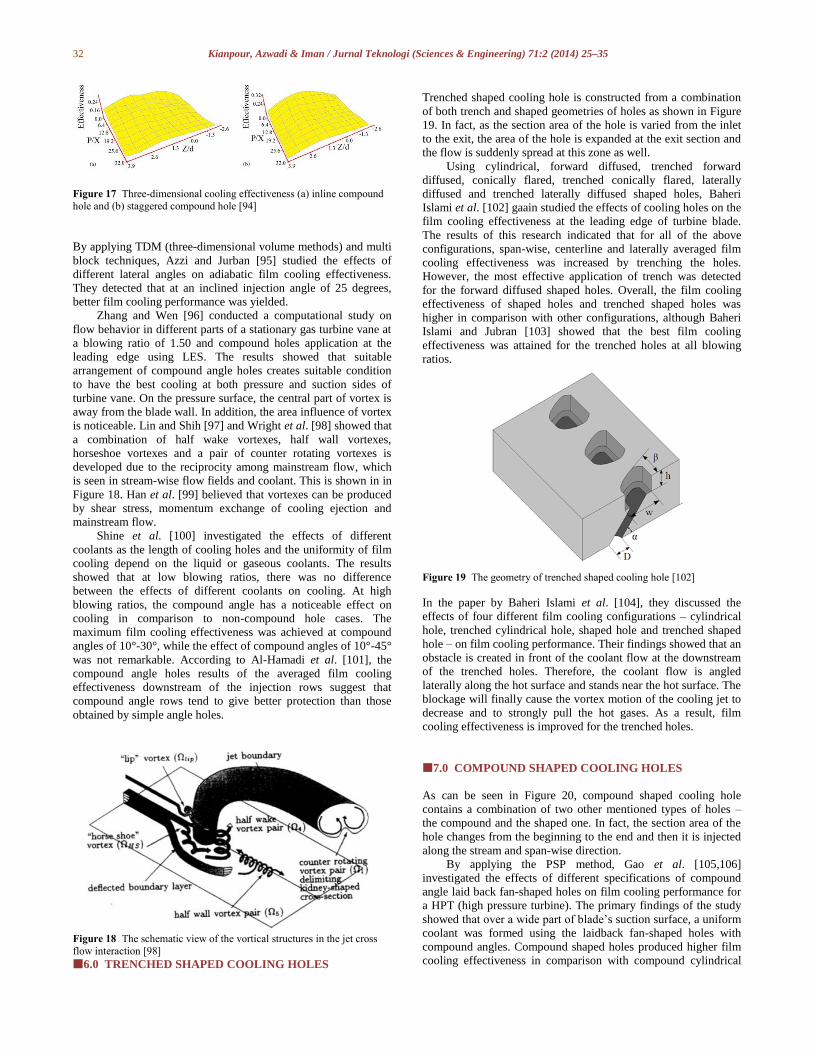
6.0 TRENCHED SHAPED COOLING HOLES
Trenched shaped cooling hole is constructed from a combination
of both trench and shaped geometries of holes as shown in Figure
19. In fact, as the section area of the hole is varied from the inlet
to the exit, the area of the hole is expanded at the exit section and
the flow is suddenly spread at this zone as well.
Using cylindrical, forward diffused, trenched forward
diffused, conically flared, trenched conically flared, laterally
diffused and trenched laterally diffused shaped holes, Baheri
Islami et al. [102] gaain studied the effects of cooling holes on the
film cooling effectiveness at the leading edge of turbine blade.
The results of this research indicated that for all of the above
configurations, span-wise, centerline and laterally averaged film
cooling effectiveness was increased by trenching the holes.
However, the most effective application of trench was detected
for the forward diffused shaped holes. Overall, the film cooling
effectiveness of shaped holes and trenched shaped holes was
higher in comparison with other configurations, although Baheri
Islami and Jubran [103] showed that the best film cooling
effectiveness was attained for the trenched holes at all blowing
ratios.
Figure 19 The geometry of trenched shaped cooling hole [102]
In the paper by Baheri Islami et al. [104], they discussed the
effects of four different film cooling configurations – cylindrical
hole, trenched cylindrical hole, shaped hole and trenched shaped
hole – on film cooling performance. Their findings showed that an
obstacle is created in front of the coolant flow at the downstream
of the trenched holes. Therefore, the coolant flow is angled
laterally along the hot surface and stands near the hot surface. The
blockage will finally cause the vortex motion of the cooling jet to
decrease and to strongly pull the hot gases. As a result, film
cooling effectiveness is improved for the trenched holes.
7.0 COMPOUND SHAPED COOLING HOLES
As can be seen in Figure 20, compound shaped cooling hole
contains a combination of two other mentioned types of holes –
the compound and the shaped one. In fact, the section area of the
hole changes from the beginning to the end and then it is injected
along the stream and span-wise direction.
By applying the PSP method, Gao et al. [105,106]
investigated the effects of different specifications of compound
angle laid back fan-shaped holes on film cooling performance for
a HPT (high pressure turbine). The primary findings of the study
showed that over a wide part of blade’s suction surface, a uniform
coolant was formed using the laidback fan-shaped holes with
compound angles. Compound shaped holes produced higher film
cooling effectiveness in comparison with compound cylindrical
33 Kianpour, Azwadi & Iman / Jurnal Teknologi (Sciences & Engineering) 71:2 (2014) 25–35
cooling holes, particularly for both suction and pressure sides and
at elevated blowing ratios. This is in agreement with previous
studies by Hong-Wook Lee et al. [107] and Mhetras et al. [108].
Figure 20 The geometry of compound shaped cooling hole [105]
Bell et al. [109] determined the adiabatic film cooling
effectiveness downstream of cylindrical round simple angle holes,
laterally diffused simple angle holes, laterally diffused compound
angle holes, forward diffused simple angle holes and forward
diffused compound angle holes. They investigated the effects of a
range of blowing ratios from 0.4 to 1.4, momentum flux ratios
from 0.17 to 3.5 and density ratios from 0.9 to 1.4 as well. In
comparison with simple holes, higher span-wise averaged
effectiveness was obtained within unlimited blowing ratios and
momentum flux ratios downstream of laterally diffused compound
angle.
Heneka et al. [110] designed a flat plate with cooling holes
and plenum to determine the effect of different sharp edge
diffused laidback fan-shaped cooling holes. They indicated that at
elevated blowing ratios, the film cooling performance became
better because at shallow inclination angles, the momentum of
injected flow reduced and the coolant attached to the surface.
Further away from injection holes, at x/D>20, no significant
effect was observed by compound angle variation. At fixed SP/D
ratio, the extended range of cooled surface was affected as the
area ratio changed. However, a noticeable loss of film cooling
effectiveness was seen when the area ratio went down below the
specific magnitude.
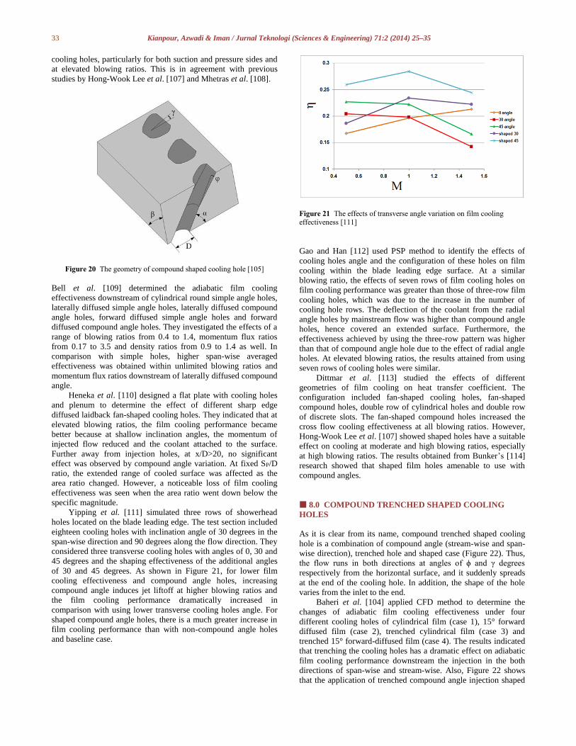
Yipping et al. [111] simulated three rows of showerhead
holes located on the blade leading edge. The test section included
eighteen cooling holes with inclination angle of 30 degrees in the
span-wise direction and 90 degrees along the flow direction. They
considered three transverse cooling holes with angles of 0, 30 and
45 degrees and the shaping effectiveness of the additional angles
of 30 and 45 degrees. As shown in Figure 21, for lower film
cooling effectiveness and compound angle holes, increasing
compound angle induces jet liftoff at higher blowing ratios and
the film cooling performance dramatically increased in
comparison with using lower transverse cooling holes angle. For
shaped compound angle holes, there is a much greater increase in
film cooling performance than with non-compound angle holes
and baseline case.
Figure 21 The effects of transverse angle variation on film cooling effectiveness [111]
Gao and Han [112] used PSP method to identify the effects of
cooling holes angle and the configuration of these holes on film
cooling within the blade leading edge surface. At a similar
blowing ratio, the effects of seven rows of film cooling holes on
film cooling performance was greater than those of three-row film
cooling holes, which was due to the increase in the number of
cooling hole rows. The deflection of the coolant from the radial
angle holes by mainstream flow was higher than compound angle
holes, hence covered an extended surface. Furthermore, the
effectiveness achieved by using the three-row pattern was higher
than that of compound angle hole due to the effect of radial angle
holes. At elevated blowing ratios, the results attained from using
seven rows of cooling holes were similar.
Dittmar et al. [113] studied the effects of different
geometries of film cooling on heat transfer coefficient. The
configuration included fan-shaped cooling holes, fan-shaped
compound holes, double row of cylindrical holes and double row
of discrete slots. The fan-shaped compound holes increased the
cross flow cooling effectiveness at all blowing ratios. However,
Hong-Wook Lee et al. [107] showed shaped holes have a suitable
effect on cooling at moderate and high blowing ratios, especially
at high blowing ratios. The results obtained from Bunker’s [114]
research showed that shaped film holes amenable to use with
compound angles.
8.0 COMPOUND TRENCHED SHAPED COOLING
HOLES
As it is clear from its name, compound trenched shaped cooling
hole is a combination of compound angle (stream-wise and span-
wise direction), trenched hole and shaped case (Figure 22). Thus,
the flow runs in both directions at angles of ϕ and γ degrees
respectively from the horizontal surface, and it suddenly spreads
at the end of the cooling hole. In addition, the shape of the hole
varies from the inlet to the end.
Baheri et al. [104] applied CFD method to determine the
changes of adiabatic film cooling effectiveness under four
different cooling holes of cylindrical film (case 1), 15° forward
diffused film (case 2), trenched cylindrical film (case 3) and
trenched 15° forward-diffused film (case 4). The results indicated
that trenching the cooling holes has a dramatic effect on adiabatic
film cooling performance downstream the injection in the both
directions of span-wise and stream-wise. Also, Figure 22 shows
that the application of trenched compound angle injection shaped

34 Kianpour, Azwadi & Iman / Jurnal Teknologi (Sciences & Engineering) 71:2 (2014) 25–35
hole provides the maximum film cooling. The ratio of the
trenched hole length to diameter affects the film cooling and
coolant injection.
Figure 22 The schematic view of compound trenched shaped cooling
hole [104]
9.0 SUMMARY
To have a better engine performance, the combustor’s outlet
temperature needs to be increased. However, hot flows develop
non-uniformities and adverse conditions can damage the critical
parts downstream the combustion chamber. The most well-known
type of cooling preservation is film-cooling. However, the
performance of traditional cooling holes is not good at higher
blowing ratios. So far, many researchers have concentrated to
design new shapes of cooling holes to modify the film cooling
performance. Generally, the findings of these studies indicate that
designing more rows of film cooling holes is more effective for
film cooling performance. Also, when the distance between two
adjacent holes is small, a better jet orifice cooling is achieved.
Trenching cooling holes allows the injected coolant to spread
before exiting the cooling holes. The studies considered the
effects of width and depth of cooling holes for both row trench
and individual trench. However, the results show that row trench
is more effective than the other types. According to the findings,
the narrow trench has better effect on film cooling performance.
The best cooling performance is obtained at trench depth of 0.75.
With shaped holes, the coolant attached to the surface and the film
cooling performance which is achieved is thus higher than with
cylindrical ones. In compound angle holes, the increase of jet’s
free stream interaction leads to the enhancement of normalized
heat transfer coefficient, especially at the orientation angle of
above 60 degrees.
From previous studies, it is found that the effects of trenched
depth and width changes, and eventually the individual and row
trenched cooling holes on flow behavior around turbine blades are
considered. However, there are several unanswered questions.
How trenched cooling holes modify the film cooling performance
at the combustor end wall surface compared to cylindrical case?
What is the optimum depth and width for the trenched cooling
holes located at the combustor end wall surface? What are the
effects of using row trenched cooling holes with different
alignment angles on film cooling performance at the combustor
exit? How does flow behaves under different blowing ratios for
trenched cases at the end of combustor?
Acknowledgement
The authors would like to thank Universiti Teknologi Malaysia
and the Ministry of Education of Malaysia for supporting this
research activity. This research was financially supported by the
Research University Grant 06H23.
References
[1] S.S. Vakil, K.A.Thole. 2005. Journal of Engineering for Gas Turbines
and Power. 127: 257
[2] J. Polezhaev. 1997. Energy Conversion and Management. 38: 1123.
[3] A. Kassab, E. Divo, J. Heidmann, E. Steinthorsson, F. Rodriguez. 2003. International Journal of Numerical Methods for Heat & Fluid Flow. 13:
581.
[4] B. Leger, P. Miron, J.M. Emidio. 2003. International Journal of Heat
and Mass Transfer.46: 1215.
[5] G. Xie, B. Sunden. 2010. Journal of Heat Transfer Engineering. 31: 527.
[6] C. Shuping. 2008. Film cooling enhancement with surface restructure.
Doctor Philosophy. University of Pittsburgh. Pennsylvania. [7] G. Scheepers, R.M. Morris. 2009. Journal of Turbomachinery. 131:
044501.
[8] M.K. Harrington, M.A. McWaters, D. G. Bogard, C.A. Lemmon, K.A.
Thole. 2001. Journal of Turbomachinery. 123: 798.
[9] I. Koc, C. Parmaksızoglu, M. Cakan. 2006. Energy Conversion and
Management. 47: 1231.
[10] L. Yuzhen, S. Bo, L. Bin, L. Gaoen. 2006. Journal of Heat Transfer. 128:
192. [11] W. Ai, T.H. Fletcher. 2012. Journal of Turbomachinery. 134: 041020.
[12] L. Cun-liang, Z. Hui-ren, Z. Zong-wei, X. Du-chun. 2012. International
Journal of Heat and Mass Transfer. 55: 6832.
[13] Y.L. Jun, K. Shun. 2013. International Journal of Heat and Mass
Transfer. 56: 158.
[14] K. Abdullah, K.I. Funazaki. 2012. AEROTECH IV Conference, Kuala
Lumpur. Malaysia.
[15] S. Sarkar, T. K. Bose. 1995. Sadhana. 20: 915. [16] H. Nasir, S. V. Ekkad, S. Acharya. 2001. Experimental Thermal and
Fluid Science. 25: 23.
[17] S. R. Shine, S. Sunil Kumar, B. N. Suresh. 2013. Energy Conversion and
Management. 68: 54.
[18] C.A. Hale, M.W. Plesniak, S. Ramadhyani. 2000. Journal of
Turbomachinery. 122: 553.
[19] M.B. Jovanovic, H.C. De Lange, A.A. Van Steenhoven. 2006. International Journal of Heat and Fluid Flow. 27: 42.
[20] M.B. Jovanovic, H.C. De Lange, A.A. Van Steenhoven. 2008.
International Journal of Heat and Fluid Flow. 29: 377.
[21] S. D. Peterson, M.W. Plesniak. 2002. Experiments in Fluids. 33: 889.
[22] M.W. Plesniak. 2006. Journal of Applied Mechanics. 73: 474.
[23] K. Nakabe, K. Inaoka, T.AI, K. Suzuki. 1997. Energy Conversion and
Management. 38: 1145.
[24] C.A. Hale, M.W. Plesniak, S. Ramadhyani. 2000. Journal of Turbomachinery. 122: 553.
[25] S.W. Burd, T.W. Simon. 1999. Journal of Turbomachinery. 121: 243.
[26] A. Azzi, B.A. Jubran. 2003. International Journal of Heat and Mass
Transfer. 39: 345.
[27] S. Bernsdorf, M. Rose, R.S. Abhari. 2006. Journal of Turbomachinery.
128: 141.
[28] X. Yong-gang, W. Qiang. 2013. Applied Mechanics and Materials. 278: 267.
[29] G.W. Jumper, W. C. Elrod, R. B. Rivir. 1991. Journal of
Turbomachinery. 113: 479.
[30] C. Saumweber, A. Schulz. 2012. Journal of Turbomachinery. 134:
061008.
[31] H.A. Mohammed, Y.K. Salman. 2007. Energy Conversion and
Management. 48: 2233.
[32] F. Nemdili, A. Azzi, B.A. Jubran. 2011. International Journal of Heat and Fluid Flow. 21: 46.
[33] S. Li, P. Tao, L. Li-xian, G. Ting-ting, Y. Bin. 2007. International
Conference on Power Engineering. Hangzhou, China.
[34] D.J. Mee, P.T. Ireland, S. Bather. 1999. Experiments in Fluids. 27: 273.
[35] H. Nasir, S. Acharya, S. Ekkad. 2003. International Journal of Heat and
Fluid Flow. 24: 657.
[36] D.A. Rowbury, M.L. G. Oldfield, G. D. Lock. 2001. Journal of
Turbomachinery. 123: 593.
35 Kianpour, Azwadi & Iman / Jurnal Teknologi (Sciences & Engineering) 71:2 (2014) 25–35
[37] D.A. Rowbury, M.L.G. Oldfield, G. D. Lock. 2001. Journal of
Turbomachinery. 123: 258.
[38] L. Tarchi, B. Facchini, F. Maiuolo, D. Coutandin. 2012. Journal of
Engineering for Gas Turbines and Power. 134: 041505.
[39] D.W. Milanes, D.R. Kirk, K.J. Fidkowski, I.A. Waitz. 2006. Journal of Engineering for Gas Turbines and Power. 128: 318.
[40] M.D. Barringer, O.T. Richard, J.P. Walter, S.M. Stitzel, K.A.Thole.
2002. Journal of Turbomachinery. 124: 508.
[41] L. Li, T. Liu, X. F. Peng. 2005. Applied Thermal Engineering. 25: 3013.
[42] J.J. Scrittore. 2008. Experimental Study of the Effect Of Dilution Jets On
Film Cooling Flow In A Gas Turbine Combustor. PhD theses. Virginia
Polytechnic Institute and State University. [43] L. Cun-liang, Z. Hui-ren, B. Jiang-tao, X. Du-chun. 2010. International
Journal of Heat and Mass Transfer. 53: 5232.
[44] L. Cun-liang, Z. Hui-ren, B. Jiang-tao, X. Du-chun. 2011. Journal of
Turbomachinery. 133: 011020.
[45] C.L. Liu, H. R. Zhu, J. T. Bai. 2012. Journal of Turbomachinery. 134:
011021.
[46] R.S. Bunker. 2011. Journal of Turbomachinery. 133: 011022.
[47] J.E. Sargison, M.L.G. Oldfield, S. M. Guo, G.D. Lock, A.J. Rawlinson. 2005. Experiments in Fluids. 38: 304.
[48] G. Barigozzi, G. Franchini, A. Perdichizzi. 2007. Journal of
Turbomachinery. 129: 212.
[49] L. Xiangyun, T. Zhi, D. Shuiting, X. Guoqiang. 2013. Applied Thermal
Engineering. 50: 1186.
[50] E.B.B. Joshua, F. T. Davidson, D.G. Bogard, D.R. Johns. 2011. Journal
of Turbomachinery. 133: 031020–1.
[51] A.A. Thrift, K.A. Thole, S. Hada. 2012. Journal of Turbomachinery. 134: 061019.
[52] S.P. Lynch, K.A. Thole. 2008. Journal of Turbomachinery. 130: 041019.
[53] E. Kianpour, N.A.C. Sidik, M. Agha Seyyed Mirza Bozorg. 2012.
AEROTECH IV. Kuala Lumpur. Malaysia.
[54] E. Kianpour, N.A.C. Sidik, M. Agha Seyyed Mirza Bozorg. 2012. Jurnal
Teknologi. 58: 5.
[55] N. Sundaram, K. A. Thole. 2009. Journal of Turbomachinery. 131: 041007.
[56] N. Sundaram, K.A. Thole. 2008. Journal of Turbomachinery. 130:
041013.
[57] S. A. Lawson, K.A.Thole. 2012. Journal of Turbomachinery. 134:
051040.
[58] S.K. Waye, D.G. Bogard. 2007. Journal of Turbomachinery. 129: 294.
[59] L. Yiping, A.Dhungel, S.V. Ekkad, R.S. Bunker. 2009. Journal of
Turbomachinery. 131: 011003. [60] G. Barigozzi, G. Franchini, A. Perdichizzi, S. Ravelli. 2012. Journal of
Turbomachinery. 134: 041009.
[61] R.P. Somawardhana, D.G. Bogard. Journal of Turbomachinery. 131:
011010.
[62] K.L. Harrison, J.R. Dorrington, J.E. Dees, D.G. Bogard, R.S. Bunker.
2009. Journal of Turbomachinery. 131: 011012.
[63] L. Yiping, S.V. Ekkad. 2006.9th AIAA/ASME Joint Thermophysics and
Heat Transfer Conference. The United States of America, California. [64] W. Ai, R.G. Laycock, D.S. Rappleye, T.H. Fletcher, J.P. Bons.
2011.Energy & Fuels. 25: 1066.
[65] F.H. Asghar, M.J. Hyder. 2011. Energy Conversion and Management.
52: 329.
[66] G. Barigozzi, G. Benzoni, G. Franchini, A. Perdichizzi. 2006. Journal of
Turbomachinery. 128: 43.
[67] K. D. Lee, K. Y. Kim. 2010. International Journal of Heat and Mass Transfer. 53: 2996.
[68] K.D. Lee, K.Y. Kim. 2011. International Journal of Heat and Fluid
Flow. 32: 226.
[69] K.D. Lee, K.Y. Kim. 2012. Journal of Heat Transfer. 134: 101702.
[70] C. Saumweber, A. Schulz. 2004. Journal of Turbomachinery, 126: 237.
[71] X.Z. Zhang, I. Hassan. 2006. International Journal of Heat and Fluid
Flow. 16: 848.
[72] Z. Gao, D. Narzary, J.C. Han. 2009. Journal of Turbomachinery. 131: 041004.
[73] W. Colban, K.A. Thole, M. Haendler. 2008. Journal of Turbomachinery.
130: 031007.
[74] C. Saumweber, A. Schulz, S. Wittig. 2003. Journal of Turbomachinery.
125: 65.
[75] C. Saumweber, A. Schulz. 2012. Journal of Turbomachinery. 134:
061007. [76] G. Barigozzi, G. Franchini, A. Perdichizzi, S. Ravelli. 2010.
International Journal of Heat and Fluid Flow. 31: 576.
[77] R.J. Fawcett, A.P.S.Wheeler, L. He, R. Taylor. Journal of
Turbomachinery. 134: 021015.
[78] W. Peng, P.X. Jiang. 2012. Experimental Heat Transfer. 25: 282.
[79] S. Bayraktar, T. Yılmaz. 2011. Energy Conversion and Management. 52:
1914.
[80] L.Zhang, T. Guo, S. Li, J. Liu. 2007. International Conference on Power
Engineering, Hangzhou, China.
[81] W. Colban, K.A. Thole, M. Haendler. 2007. Journal of Turbomachinery. 129: 23.
[82] W. Colban, A. Gratton, K.A. Thole, M. Haendler. 2006. Journal of
Turbomachinery. 128: 53.
[83] W. Colban, K. Thole. 2007. International Journal of Heat and Fluid
Flow. 28: 341.
[84] W.L. Sang, R.B. Jong, S.L. Dae. 1998. KSME International Journal. 12:
301. [85] M. Gritsch, A. Schulz, S. Wittig. 2001. Journal of Turbomachinery. 123:
781.
[86] V. Aga, R.S. Abhari. 2011. Journal of Turbomachinery. 133: 031029–1.
[87] B.A.Jubran, A.K. Al-Hamadi, G. Theodoridis. 1997. Journal of Heat and
Mass Transfer. 33: 93.
[88] B. Han, D.K. Sohn, J.S. Lee. 2002. KSME International Journal. 16:
1137.
[89] I.C. Lee, Y.C. Chang, P.P. Ding, P.H. Chen. 2005. Journal of the Chinese Institute of Engineers. 28: 827.
[90] V. Aga,. M. Rose, R. S. Abhari. 2008. Journal of Turbomachinery. 130:
031005–1.
[91] H. L. Jung, K. C. Young. 1998. KSME International Journal. 12: 963.
[92] S. Stitzel, K.A. Thole. 2004. Journal of Turbomachinery. 126: 122.
[93] B.A. Jubran, B.Y. Maiteh. 1999. Heat and Mass Transfer. 34: 495.
[94] B.Y. Maiteh, B.A. Jubran. 2004. Energy Conversion and Management.
45: 1457. [95] A. Azzi, B.A. Jubran. 2004. Heat and Mass Transfer. 40: 501.
[96] L. Zhang, G. Wen. 2011. The Tenth International Conference on
Electronic Measurement & Instruments. China.
[97] Y.L. Lin, T.I.P. Shih. 2001. Journal of Heat Transfer. 123: 645.
[98] L.M. Wright, S.T. McClain, M.D. Clemenson. 2011. Journal of
Turbomachinery.133: 041023.
[99] C. Han, J. Ren, H. d. Jiang. 2012. International Journal of Heat and Mass Transfer. 55: 4232.
[100] S.R. Shine, S.S. Kumar, B.N. Suresh. 2011. Heat Mass Transfer. 48: 849.
[101] A.K. Al-Hamadi, B.A. Jurban, G. Theodoridis. 1998. Energy Conversion
and Management. 39: 1449.
[102] S. Baheri Islami, S.P. Alavi Tabrizi, B.A. Jubran, E. Esmaeilzadeh. 2010.
Heat Transfer Engineering. 31: 889.
[103] S. Baheri Islami, B.A. Jubran. 2011. Heat Mass Transfer. 48: 831.
[104] S. Baheri Islami, S.P. Alavi Tabrizi, B.A. Jubran. 2008. Numerical Heat Transfer. 53: 308.
[105] Z. Gao, D.P.Narzary, J.C. Han. 2008. International Journal of Heat and
Mass Transfer. 51: 2139–2152.
[106] Z. Gao, D.P. Narzary, H. Je-Chin. 2009. Journal of Turbomachinery.
131: 011019.
[107] L. Hong-Wook, P. Jung-Joon, S. L. Joon. 2002. International Journal of
Heat and Mass Transfer. 45: 145.
[108] S. Mhetras, J.C. Han, R. Rudolph. 2012. Journal of Turbomachinery. 134: 011004.
[109] C.M. Bell, H. Hamakawa, P.M. Ligrani. 2000. Journal of Heat Transfer.
122: 224.
[110] C. Heneka, A. Schulz, H.J. Bauer, A. Heselhaus, M.E. Crawford. 2012.
Journal of Turbomachinery. 134: 041015.
[111] L.Yiping, D. Allison, S.V. Ekkad. 2007. International Journal of Heat
and Fluid Flow. 28: 922. [112] Z. Gao, J.C. Han. 2009. Journal of Heat Transfer. 131: 061701.
[113] J. Dittmar, A. Schulz, S. Wittig. 2007. Journal of Turbomachinery. 125:
57. [114] R.S. Bunker. 2005. Journal of Heat Transfer. 127: 441