JUNO IC20LED (06LM, 09LM, 14LM) & IC22LED (06LM, 09LM ... · negro del accesorio al caliente, el...
4
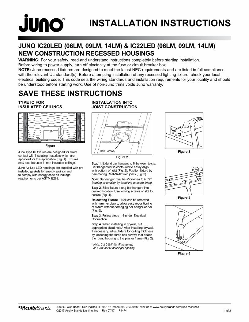
1 of 2 1300 S. Wolf Road • Des Plaines, IL 60018 • Phone 800-323-5068 • Visit us at www.acuitybrands.com/juno-recessed ©2017 Acuity Brands Lighting, Inc Rev 07/17 P4474 INSTALLATION INSTRUCTIONS SAVE THESE INSTRUCTIONS JUNO IC20LED (06LM, 09LM, 14LM) & IC22LED (06LM, 09LM, 14LM) NEW CONSTRUCTION RECESSED HOUSINGS WARNING: For your safety, read and understand instructions completely before starting installation. Before wiring to power supply, turn off electricity at the fuse or circuit breaker box. NOTE: Juno recessed fixtures are designed to meet the latest NEC requirements and are listed in full compliance with the relevant UL standard(s). Before attempting installation of any recessed lighting fixture, check your local electrical building code. This code sets the wiring standards and installation requirements for your locality and should be understood before starting work. Use of non-Juno trims voids Juno warranty. INSTALLATION INTO JOIST CONSTRUCTION Figure 3 Figure 4 Figure 5 Figure 2 Hex Screws Figure 1 TYPE IC FOR INSULATED CEILINGS Juno Type IC fixtures are designed for direct contact with insulating materials which are approved for this application (Fig. 1). Fixtures may also be used in non-insulated ceilings. Juno Air-Loc LED housings are supplied with pre- installed gaskets for energy savings and to comply with energy code air leakage requirements per ASTM E283. Step 1. Extend bar hangers to fit between joists. Bar hanger foot is contoured to easily align with bottom of joist (Fig. 2). Position fixture by hammering Real-Nails ® into joists (Fig. 3). Note: Bar hanger may be shortened to fit 12” framing or smaller by breaking at score lines). Step 2. Slide fixture along bar hangers into desired location. Use locking screws or slot to secure (Fig. 4). Relocating Fixture – Nail can be removed with hammer claw to allow easy repositioning of fixture without damaging bar hanger or nail (Fig. 5). Step 3. Follow steps 1-4 under Electrical Connection. Step 4. When installing in drywall, cut appropriate sized hole.* After installing drywall, if necessary, adjust fixture for ceiling thickness by loosening the three hex screws that attach the round housing to the plaster frame (Fig. 2). * Note: Cut 5-5/8” (for 5” housings) or 6-7/8” (for 6” housings) opening.
Transcript of JUNO IC20LED (06LM, 09LM, 14LM) & IC22LED (06LM, 09LM ... · negro del accesorio al caliente, el...
1 of 21300 S. Wolf Road • Des Plaines, IL 60018 • Phone 800-323-5068 • Visit us at www.acuitybrands.com/juno-recessed ©2017 Acuity Brands Lighting, Inc Rev 07/17 P4474
INSTALLATION INSTRUCTIONS
SAVE THESE INSTRUCTIONS
JUNO IC20LED (06LM, 09LM, 14LM) & IC22LED (06LM, 09LM, 14LM) NEW CONSTRUCTION RECESSED HOUSINGSWARNING: For your safety, read and understand instructions completely before starting installation. Before wiring to power supply, turn off electricity at the fuse or circuit breaker box.NOTE: Juno recessed fixtures are designed to meet the latest NEC requirements and are listed in full compliance with the relevant UL standard(s). Before attempting installation of any recessed lighting fixture, check your local electrical building code. This code sets the wiring standards and installation requirements for your locality and should be understood before starting work. Use of non-Juno trims voids Juno warranty.
INSTALLATION INTO JOIST CONSTRUCTION
Figure 3
Figure 4
Figure 5
Figure 2
Hex Screws
Figure 1
TYPE IC FOR INSULATED CEILINGS
Juno Type IC fixtures are designed for direct contact with insulating materials which are approved for this application (Fig. 1). Fixtures may also be used in non-insulated ceilings.
Juno Air-Loc LED housings are supplied with pre-installed gaskets for energy savings and to comply with energy code air leakage requirements per ASTM E283.
Step 1. Extend bar hangers to fit between joists. Bar hanger foot is contoured to easily align with bottom of joist (Fig. 2). Position fixture by hammering Real-Nails® into joists (Fig. 3).
Note: Bar hanger may be shortened to fit 12” framing or smaller by breaking at score lines).
Step 2. Slide fixture along bar hangers into desired location. Use locking screws or slot to secure (Fig. 4).
Relocating Fixture – Nail can be removed with hammer claw to allow easy repositioning of fixture without damaging bar hanger or nail (Fig. 5).
Step 3. Follow steps 1-4 under Electrical Connection.
Step 4. When installing in drywall, cut appropriate sized hole.* After installing drywall, if necessary, adjust fixture for ceiling thickness by loosening the three hex screws that attach the round housing to the plaster frame (Fig. 2).
* Note: Cut 5-5/8” (for 5” housings) or 6-7/8” (for 6” housings) opening.

2 of 21300 S. Wolf Road • Des Plaines, IL 60018 • Phone 800-323-5068 • Visit us at www.acuitybrands.com/juno-recessed ©2017 Acuity Brands Lighting, Inc Rev 07/17 P4474
WARRANTY5-year limited warranty. Complete warranty terms located at www.acuitybrands.com/CustomerResources/Terms_and_conditions.aspxTechnical Services Phone (888) 387-2212
INSTALLATION INSTRUCTIONS
JUNO IC20LED (06LM, 09LM, 14LM) & IC22LED (06LM, 09LM, 14LM) NEW CONSTRUCTION RECESSED HOUSINGS
Step 1. Provide electrical service according to your local electrical code to the wiring box located on the plaster frame. Supply wire insulation must be rated for at least 90°C.
Step 2. Remove wiring box cover. Remove the appropriate knock-out(s) to accommodate the type of electrical service to be used/allowed by your local electrical code (Fig. 8):
Metal Conduit. Remove appropriate round knock-out(s) and connect conduit to wiring box with proper connectors (not supplied).
12/2 or 14/2 Non-Metallic Sheathed Cable (Type NM-B). Remove appropriate D-shaped cable knock-out(s). Insert NM-B cable through cable trap and make a 90˚L-shaped bend in cable as shown (Fig. 9).
12/3 or 14/3 Cable (Type NM-B). Remove appropriate round knockouts and connect cable with proper electrical connectors (not supplied and not shown).
Step 3. Strip supply wire 3/8” and insert each supply wire into appropriate connector. Connect black fixture wire to hot, white fixture wire to neutral and green fixture wire to ground. (Fig. 8).
Connect violet (+) and gray (-) dimmer wires, if utilizing 0-10V dimmer.
Step 4. Place all wiring and connectors back in wiring box and replace cover.
Figure 7
* Note: Cut 5-5/8” (for 5” housings) or 6-7/8” (for 6” housings) opening.
DRIVER REPLACEMENTDriver replacements must be performed by a qualified electrician. Replacement kits can be ordered to match your specific fixture type. The replacement kits include detailed instruction for driver replacement. Remove inner housing from fixture to access driver (Fig. 6).
TRIM INSTALLATIONAfter ceiling is finished and painted, remove paint shield from fixture. Discard or recycle. To install trims using COIL SPRINGS remove OPTIC REFLECTOR by rotating 1/4 turn counter-clockwise (Fig. 10). Connect trim springs to fixture L-BRACKETS as shown (Fig. 11). Take note of flange details at top of OPTIC REFLECTOR, align and insert in fixture and rotate 1/4 turn clockwise until it stops.
To install trims with TORSION SPRINGS:
For lensed trims, it is not necessary to remove OPTIC REFLECTOR. For lensed trims equipped with an internal reflector, remove the reflector supplied with the trim and discard or recycle.
For hyperbolic trims, follow instructions provided with the trim.
FIXTURE DIMMINGUniversal Voltage (MVOLT) Downlights: Universal input voltage (120VAC thru 277VAC) housings. Dimmable with the use of most 0-10V wall box dimmers.120VAC (120) Downlights: 120VAC input voltage housings. Dimmable with the use of most incandescent, magnetic low voltage or electronic low voltage* wall box dimmers.Consult Juno Product Services or website for compatibility.*Electronic low voltage dimmers require a neutral wire connection in the wall box.
Figure 11
L-Bracket Coil Spring
Step 1. Locate center of proposed opening on ceiling tile and cut appropriate sized hole.*Step 2. Place ceiling tile in T-bar grid.Step 3. Place fixture into position and snap bar hanger foot with integral T-bar notch onto T-bars (Fig. 6). Additional holes provided for securing with wire or screws (Fig. 7).Step 4. Follow Steps 1-4 under Electrical Connection.
Figure 9
NM-B Cable Knock-out (D-Shaped)
NM-B Cable Trap
(4 Places)
NM-B Cable
12/2 or 14/2 NM-B Installation
Figure 10
Optic Reflector
Figure 8
Knock-out
Quick Connector
0-10V Dimming Wires (-MVOLT models only)
INSTALLATION INTO SUSPENDED CEILING
ELECTRICAL CONNECTION INSTRUCTIONS
Figure 6
LED Driver
LED Driver
1 de 21300 S. Wolf Road • Des Plaines, IL 60018 • Teléfono 800-323-5068 • Visítenos en www.acuitybrands.com/juno-recessed©2017 Acuity Brands Lighting, Inc. Rev 07/17 P4474
INSTRUCCIONES DE INSTALACIÓN
GUARDE ESTAS INSTRUCCIONES
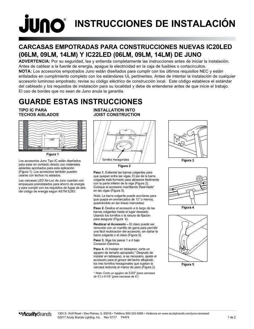
CARCASAS EMPOTRADAS PARA CONSTRUCCIONES NUEVAS IC20LED (06LM, 09LM, 14LM) Y IC22LED (06LM, 09LM, 14LM) DE JUNOADVERTENCIA: Por su seguridad, lea y entienda completamente las instrucciones antes de iniciar la instalación. Antes de cablear a la fuente de energía, apague la electricidad en la caja de fusibles o cortacircuitos.NOTA: Los accesorios empotrados Juno están diseñados para cumplir con los últimos requisitos NEC y están enlistados en cumplimiento completo con los estándares UL pertinentes. Antes de intentar la instalación de cualquier accesorio luminoso empotrado, revise su código eléctrico de construcción local. Este código establece el estándar del cableado y los requisitos de instalación para su localidad y debe de entenderse antes de que inicie el trabajo. El uso de bordes que no sean de Juno anula la garantía.
INSTALLATION INTO JOIST CONSTRUCTION
Figura 3
Figura 4
Figura 5
Figura 2
Tornillos Hexagonales
Figura 1
TIPO IC PARA TECHOS AISLADOS
Los accesorios Juno Tipo IC están diseñados para estar en contacto directo con materiales aislantes aprobados para esta aplicación (Figura 1). Los accesorios también pueden usarse con techos no aislados.
Las carcasas LED Air-Loc de Juno cuentan con empaques preinstalados para ahorro de energía y para cumplir con los requisitos de fugas de aire del código de energía según ASTM E283.
Paso 1. Extienda las barras colgantes para que quepan entre las vigas. El pie de la barra colgante está formado para alinearse fácilmente con la parte inferior de la viga (Figura 2). Coloque el accesorio martillando Real-Nails® en las vigas (Figura 3).
Nota: La barra colgante puede acortarse para que quepa en enmarcados de 12” o menos, quebrándolo en las líneas marcadas).
Paso 2. Deslice el accesorio a lo largo de las barras colgantes hasta el lugar deseado. Usando los tornillos o la ranura de fijación para asegurar (Figura 4).
Reubicar el Accesorio – El clavo puede ser removido con un martillo de garra para permitir una fácil reubicación del accesorio, sin dañar la barra colgante o el clavo (Figura 5).
Paso 3. Siga los pasos 1 a 4 bajo Conexión Eléctrica.
Paso 4. Al Instalar en tablayeso, corte un agujero de tamaño apropiado.* Después de instalar en tablayeso, si es necesario, ajuste el accesorio para el grosor del techo aflojando los tres tornillos hexagonales que sujetan la carcasa redonda al marco de yeso (Figura 2).
* Nota: Corte un agujero de 5-5/8” (para carcasas de 5”) o 6-7/8” (para carcasas de 6”).

2 de 2
GARANTÍAGarantía limitada de 5 años. Términos completos de garantía ubicados en www.acuitybrands.com/CustomerResources/Terms_and_conditions.aspx
Teléfono de servicio de técnicos (888) 387-2212
1300 S. Wolf Road • Des Plaines, IL 60018 • Teléfono 800-323-5068 • Visítenos en www.acuitybrands.com/juno-recessed©2017 Acuity Brands Lighting, Inc. Rev 07/17 P4474
INSTRUCCIONES DE INSTALACIÓN
CARCASAS EMPOTRADAS PARA CONSTRUCCIONES NUEVAS IC20LED (06LM, 09LM, 14LM) Y IC22LED (06LM, 09LM, 14LM) DE JUNO
Paso 1. Ubique el centro de la abertura planteada en el panel del techo y corte un agujero de tamaño apropiado*.Paso 2. Coloque el panel del techo en la rejilla de barras-T.Paso 3. Ponga el accesorio en su posición y presione la barra colgante con la muesca para Barras-T integrada en las Barras-T (Figura 6). Se proporcionan agujeros adicionales para asegurar con alambre o con tornillos (Figura 7).Paso 4. Siga los Pasos 1 a 4 bajo Conexión Eléctrica.
Paso 1. Proporcione el servicio eléctrico, según su código eléctrico local, a la caja de empalmes ubicada en el marco de yeso. El aislante de los alambres de suministro debería estar clasificado para al menos 90ºC.
Paso 2. Quite la tapa de la caja de empalmes. Quite el/los troquel(es) correspondiente(s) para dar cabida al tipo de servicio eléctrico usado/permitido por su código eléctrico local (Figura 8):
Ducto Metálico. Quite el/los troquel(es) redondo(s) correspondiente(s) y conecte el ducto a la caja de alambrado con los conectores correctos (no proporcionados).
Cable con Revestimiento No Metálico 12/2 ó 14/2 (Tipo NM-B). Quite los troqueles redondos correspondientes y conecte el cable con los conectores correctos (no proporcionados y no se muestran).
Cable 12/3 ó 14/3 (Tipo NM-B). Remove appropriate round knockouts and connect cable with proper electrical connectors (not supplied and not shown).
Paso 3. Pele el alambre de suministro 3/8” e inserte cada alambre de suministro en el conector correspondiente. Conecte el alambre negro del accesorio al caliente, el alambre blanco del accesorio al neutral y el alambre verde del accesorio a tierra. (Figura 8).
Conecte los cables del atenuador violeta (+) y gris (-), si utiliza un atenuador de 0-10V.
Paso 4. Coloque todo el alambrado y los conectores de vuelta en la caja de empalmes y vuelva a colocar la tapa.
REEMPLAZO DE IMPULSADORLos reemplazos del impulsador deben ser realizados por un electricista calificado. Los kits de reemplazo se pueden pedir para que coincidan con su tipo de dispositivo específico. Los kits de reemplazo incluyen instrucciones detalladas para el reemplazo del impulsador. Retire la carcasa interior del accesorio para acceder al impulsador (Figura 6).
INSTALACIÓN DE BORDESDespués de que el techo esté acabado y pintado, quite el protector de pintura del accesorio. Deséchelo o recíclelo. Para instalar bordes usando RESORTES quite el REFLECTOR ÓPTICO girándolo 1/4 de giro en el sentido contrarreloj (Figura 10). Conecte los resortes a los SOPORTES-L del accesorio como se muestra (Figura 11). Tome nota de los detalles de la pestaña en la parte superior del REFLECTOR ÓPTICO, alinee e inserte en el accesorio y gire 1/4 de giro en el sentido del reloj hasta que tope.
Para instalar bordes con RESORTES DE TORSIÓN:
No es necesario quitar el REFLECTOR ÓPTICO para bordes con lente. Para bordes con lente equipados con un reflector interno, quite el reflector proporcionado con el borde y deséchelo o recíclelo.
Para bordes hiperbólicos, siga las instrucciones proporcionadas con el borde.
REGULACIÓN DEL ACCESORIOLuces focales (MVOLT) de Voltaje Universal: Carcasas de voltaje de entrada universal (120VAC a 277VAC). Regulable con la mayoría de reguladores de caja de pared de 0 a 10V.Luces focales (120) de 120VAC: Carcasas de voltaje de entrada de 120VAC. Regulables usando la mayoría de reguladores de caja de pared incandescentes, magnéticos de voltaje bajo y electrónicos de voltaje bajo*.Consulte con Servicios de Productos Juno o en el sitio web para compatibilidad.*Los reguladores electrónicos de bajo voltaje requieren una conexión de alambre neutral en la caja de pared.
Figura 11
Soporte-LResorte
Figura 9
Troquel para Cable NM-B (Forma D)
Sujetador de Cable NM-B (4 Lugares)
Cable NM-B
Instalación NM-B 12/2 ó 14/2
Figura 10
Reflector Óptico
Figura 8
Troquel
Conector Rápido
Cables de atenuación 0-10V(Sólo modelos -MVOLT)
INSTALACIÓN EN UN TECHO SUSPENDIDO
INSTRUCCIONES DE CONEXIÓN ELÉCTRICA
* Nota: Corte un agujero de 5-5/8” (para carcasas de 5”) o 6-7/8” (para carcasas de 6”).
Figura 7
Figura 6
Impulsador de LED
Impulsador de LED