JUNKERS JU 88A-4 - wonderlandmodels.com · the Junkers Ju 88 was . the Luftwaffe’s primary...
10
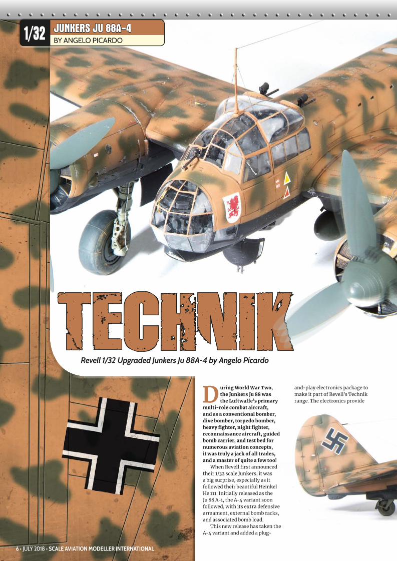
D uring World War Two, the Junkers Ju 88 was the Luftwaffe’s primary multi-role combat aircraft, and as a conventional bomber, dive bomber, torpedo bomber, heavy fighter, night fighter, reconnaissance aircraft, guided bomb carrier, and test bed for numerous aviation concepts, it was truly a jack of all trades, and a master of quite a few too! When Revell first announced their 1/32 scale Junkers, it was a big surprise, especially as it followed their beautiful Heinkel He 111. Initially released as the Ju 88 A-1, the A-4 variant soon followed, with its extra defensive armament, external bomb racks, and associated bomb load. This new release has taken the A-4 variant and added a plug- and-play electronics package to make it part of Revell’s Technik range. The electronics provide TECHNIK Revell 1/32 Upgraded Junkers Ju 88A-4 by Angelo Picardo 6 • JULY 2018 • SCALE AVIATION MODELLER INTERNATIONAL BY SACCO DE VRIES JUNKERS JU 88A-4 BY ANGELO PICARDO 1/32
Transcript of JUNKERS JU 88A-4 - wonderlandmodels.com · the Junkers Ju 88 was . the Luftwaffe’s primary...
D uring World War Two, the Junkers Ju 88 was the Luftwaffe’s primary
multi-role combat aircraft, and as a conventional bomber, dive bomber, torpedo bomber, heavy fighter, night fighter, reconnaissance aircraft, guided bomb carrier, and test bed for numerous aviation concepts, it was truly a jack of all trades, and a master of quite a few too!
When Revell first announced their 1/32 scale Junkers, it was a big surprise, especially as it followed their beautiful Heinkel He 111. Initially released as the Ju 88 A-1, the A-4 variant soon followed, with its extra defensive armament, external bomb racks, and associated bomb load.
This new release has taken the A-4 variant and added a plug-
and-play electronics package to make it part of Revell’s Technik range. The electronics provide
TECHNIKRevell 1/32 Upgraded Junkers Ju 88A-4 by Angelo Picardo
6 • JULY 2018 • SCALE AVIATION MODELLER INTERNATIONAL
BY SACCO DE VRIESJUNKERS JU 88A-4BY ANGELO PICARDO1/32
006-15-FEAT-Ju88-0718.indd 6 11/06/2018 13:55

the modeller with two motors to spin the propellers and micro LEDs to illuminate the cockpit, landing light, and wing tip and tail navigation lights.
The power pack of four AA batteries (not included) is external and has a power jack that allows it to be disconnected for transport. The various elements all connect together with push fittings and are colour-coded to ensure that even a technophobe like me can’t get it wrong. Supposedly...!
The plastic parts are supplied on thirteen light grey sprues and two clear ones. All the panel lines are engraved and feature some rather fine detail. There is a fair amount of flash, but fortunately all the mould ejector pin marks are away from any visible areas.
The transparencies are thin and clear, and while there is also some flash on these pieces, it is very easy to clean up. Two colour schemes are provided: the first is for a European-based machine with an RLM70 over RLM71 splinter pattern and an RLM65 underside.
The second scheme is for a Sicilian based aeroplane, which features a desert sand colour over an RLM65 underside – but it’s not quite that simple! The top colour has bands of RLM70 and white over it, while the underside is covered in sand-coloured squiggles (which are guaranteed to set even the most expert air brusher’s hands quivering).
The kit’s instructions are in a twenty-four page booklet with 116 assembly stages, plus two monochromatic painting and
decaling guides. All paint references are for Revell’s own range of paints, though they are cross-referenced to RLM colours where appropriate.
Even without the electronics, this would be quite an involved build, with one of the best cockpits I have ever seen in a mainstream kit. However, the Editor was not satisfied with the complexity of
the kit out of the box, so he threw in a whole lot of aftermarket!
First off was Eduard’s Big Ed set, which includes their exterior set, self-adhesive interior set, placards, seatbelts and thankfully, a set of pre-cut canopy masks. The Editor also provided a set of Master Models turned-brass gun barrels for the defensive machine guns, a brass pitot tube from Profimodeller, some resin wheels, and a beautifully printed decal sheet from Eagle Cals, which supplied another three colour options.
Assembly Stages One to Thirty-two takes you through the assembly of the impressive cockpit. Just out of the box, the cockpit is sublime. Add in Eduard’s etch and the level of detail is just ridiculous! Eduard provides a multitude of pieces to turn the kit’s plastic into an incredible work of art, with replacement
parts in brass to provide a finer look or provide missing details.
For example, the A4 variant’s defensive armament moved away from the saddle-drum magazines used in earlier models to belt-fed ammunition from large tanks. The kit does not provide any of the ammunition feeds, so Eduard have included them as very delicate brass items which, once folded into shape, can be flexed (as per the real item)
to connect the machine guns to their ammunition supply.
“THE TECHNIK BOXING ADDS THE MAGIC OF LIGHT AND MOTION, WHICH LOOKS VERY EFFECTIVE”
WWW.SAMPUBLICATIONS.COM • JULY 2018 • 7
1/32
006-15-FEAT-Ju88-0718.indd 7 11/06/2018 13:55

CONSTRUCTIONThe plastic instrument panel features raised detail, but the instrument dials and decals for the dials are flat. Eduard provides a pre-coloured etched panel in two parts that, once placed over each other form an extremely realistic-looking replica, especially if you add the wiring to the back of the panel, which I did. (Eduard’s pre-coloured, self-adhesive placards and instrument dials are the icing on the cake).
I used a fine drill bit to make pilot holes in the moulded-on instrument rears, then superglued in lengths of fine copper wire, which were then twisted together to form the bundles of wire seen behind the panel. Thin strips of masking tape were wrapped around the wire bundles to represent the fasteners that hold the individual wires together. As the clear nose makes this area very visible, I think this simple bit of detail work is well worth it.
While on the subject of drilling holes, don’t forget to drill the hole in the wing root in Stage Seven, which allows the motors and wires to pass into the wings. Revell includes two drill bits in the kit, but they are 0.8 mm in diameter, which is not big enough to make the holes to the motors to pass through.
Going back to the instrument
Basic etched parts being added to the kit’s cockpit
Wood veneer used to simulate the wooden floor
Eduard replaces or adds parts which are simplified or missed off to the kits interior
Starbord cockpit wall undergoing painting and detailing
Part I59 with pre-cut masks added to the inspection panels
Rear cockpit wall with the moulded detail removed from the radio faces, and improved etched detail added
Pilot’s side of the cockpit
Radio operator’s seat receives an etched document case and a hinge for the folding head armour
Etched wood grain floor
One of the kit’s un-delicate rudder pedals
The rather hefty sprue attachment gate
Eduard’s pre-coloured placards bring the grey cockpit to life
8 • JULY 2018 • SCALE AVIATION MODELLER INTERNATIONAL
006-15-FEAT-Ju88-0718.indd 8 11/06/2018 13:55

panel, for the clear lenses you can either paint the dials with a gloss varnish, or sandwich a piece of thin clear acetate between the two etched pieces.
The self-adhesive placards supplement the decals to really bring the cockpit to life and add a splash of colour to the otherwise drab dark grey, RLM66 interior colour.
The Eduard set also provides pre-coloured parts for the bank of radio receivers and transmitters found on the rear cockpit wall. To install these parts, you have to remove the moulded raised details from the radios. Once again the etched brass replacements build up in layers to provide a nice three dimensional look to the faces.
The pilot’s side console, with the throttle levers, flap levers, and various other controls, is very impressive out of the box. Eduard provides numerous replacement parts that, apart from the control levers (which to my eye appeared too thin), were used to replace and enhance the kit pieces.
Because there are a number of clear inspection panels in the floor, the floor panel for the pilot and radio operator/rear gunner is provided as a clear piece (Part I159). The mask set included
in the Big Ed set has masks for these, which saves you a fiddly job of cutting your own masks.
When you consider the amount of abuse they get, Luftwaffe rudder
pedals are rather delicate-looking items. The kit pedals are as fine as you can get using injection-moulding technology, but they have a fair bit of flash around
them and are connected to the sprue by rather large gates.
Hoping Eduard would replace them with some more delicate brass parts, I was rather surprised and disappointed to see that they only provide the top half of the pedal. When you consider that they provide replacement parts for plastic pieces that don’t need enhancement, it’s a shame that the rudder pedals don’t receive a full set of new parts as well.
The bomb aimer’s footrest, which is made from wood in the real aircraft, was next (Part H160). To represent this, Eduard provide a panel with a wood-grain effect etched into it. To me, however, this looked rather heavy and unconvincing. Fortunately, tucked away in the depths of my spares box, I had a piece of very thin laminate wood (acquired, free of charge, from a local tobacconist; it had been used as a divider in boxes of cigars).
Using the etched piece as a template, I trimmed a piece of the wood to size and then superglued it into place. Once set it was sanded back with fine sandpaper, then varnished and painted in RLM 66. Just as the paint was drying, I used a cotton bud dipped in thinners to cut the paint back to reveal the wood, representing the wear and tear caused by the aircrew’s boots.
By this point, It was starting to get a bit hard to keep track of which parts had been replaced and enhanced, but the cockpit was very quickly turning into an impressive looking area. The crew seats were next, enhanced
Eduard’s instrument panel
Belly gunner’s gondola with etched frame and plastic card knee pad
Wiring loom made from thin copper wire
Fuselage sides together with all that lovely cockpit detail sandwiched in between. Seat belts are Eduard items
Cockpit progress with Eduard’s radio faces added over the kit parts
Cockpit looking forward
Cockpit from above, showing the worn paint effect for the bomb aimer’s foot plate
Cockpit underside with the homemade wiring loom
WWW.SAMPUBLICATIONS.COM • JULY 2018 • 9
1/32
006-15-FEAT-Ju88-0718.indd 9 11/06/2018 13:55

with Eduard’s excellent pre-coloured Luftwaffe seatbelts.
I then turned to the fold-down seat for the gondola gunner, which is provided with an etched backrest that is hooked into place when required. The etch set also supplies the gondola safety harness and some internal framework, as well as the frame which holds the cushion pad for the gunner to lie on. No cushion is provided, but it only took a couple of minutes to shape one from a square piece of thick plastic card.
The cockpit rear wall, bulkhead (Part C149), and the rear bomb bay bulkhead (Part C150), have partial wing spars moulded integrally.
These fit into slots in the fuselage halves and provide a firm structure to fit the fuselage to, which is especially useful when you take into account the slightly unorthodox structure of the fuselages: instead of the conventional left and right
fuselage halves, you get a separate spine and belly plate. It was engineered this way to allow Revell to make various versions of the JU 88 from the kit, as different marks had a different layout of panel lines along the spine and underside.
By the time you arrive at Stage Thirty-two, most of the cockpit is assembled and work now turns to the tailwheel and its bay.
Three bulkheads fit into the fuselage to form the undercarriage bay. The instructions would have you make up the whole tail wheel assembly now and attach it in place, but it can be left off until the very end to avoid damaging it during the rest of the build.
The way the tail wheel is assembled out of the box makes it difficult to clean up seams and paint. So, I made a slight modification by trimming off the wheel mounting pins from parts G141 and 142, drilling a hole through the leg to allow a steel pin to be used as an axle, and adding the wheel later.
The plans would have you fit the electronic control package at Stage Thirty-eight, before the fuselage halves are brought together. As the top panel of the fuselage is a separate piece, I found it just as easy to fit them once the two sides were brought together, as there is plenty of room to get it all in through the open top.
Once the fuselage had set, I began with the insertion of all the electric goodies. The motors went first, fed through the holes I had drilled in the wing roots. The red-wired motor fitted to the port side and green to starboard. The port wing tip light and the leading edge landing light were then fed through the hole, followed by the starboard navigation light.
The tail light is passed through the bulkheads that form the tail wheel bay, then the battery pack connector jack is passed through the forward bulkhead, leaving its wire hanging out of the wheel bay’s fuselage opening. The last LED, for the cockpit light, is fixed in place just behind the radios in the back of the crew compartment.
The circuit board is covered by a protective sleeve and then placed inside the main fuselage, along with all the remaining wiring.
I now jumped ahead to Stage Forty-six and fitted the top
All this detail will be seen through the cockpit’s extensive glazing
Looking up into the cockpit from where the gondola will go The electronics package fitted into the fuselage
Starboard wing showing the motor, landing light and wing tip light. The wing tip has not yet been added. Note the silver foil, used to prevent the light showing through the plastic
Cockpit instrument panel coaming in place, showing where some filling and sanding was required
Join line close up
The power jack which connects to the battery pack
Starboard lower wing attached, and the wing spars
10 • JULY 2018 • SCALE AVIATION MODELLER INTERNATIONAL
006-15-FEAT-Ju88-0718.indd 10 11/06/2018 13:55
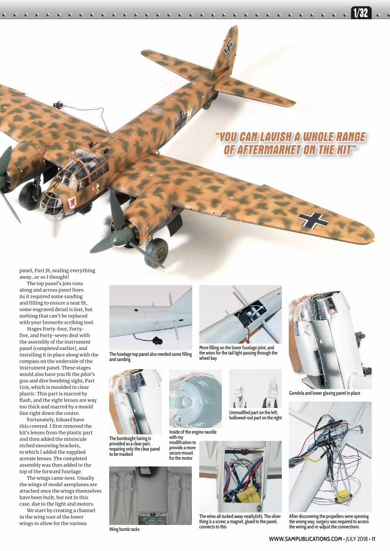
panel, Part J8, sealing everything away...or so I thought!
The top panel’s join runs along and across panel lines. As it required some sanding and filling to ensure a neat fit, some engraved detail is lost, but nothing that can’t be replaced with your favourite scribing tool.
Stages Forty-four, Forty-five, and Forty-seven deal with the assembly of the instrument panel (completed earlier), and installing it in place along with the compass on the underside of the instrument panel. These stages would also have you fit the pilot’s gun and dive bombing sight, Part I219, which is moulded in clear plastic. This part is marred by flash, and the sight lenses are way too thick and marred by a mould line right down the centre.
Fortunately, Eduard have this covered. I first removed the kit’s lenses from the plastic part and then added the miniscule etched mounting brackets, to which I added the supplied acetate lenses. The completed assembly was then added to the top of the forward fuselage.
The wings came next. Usually the wings of model aeroplanes are attached once the wings themselves have been built, but not in this case, due to the light and motors.
We start by creating a channel in the wing root of the lower wings to allow for the various
The fuselage top panel also needed some filling and sanding
Inside of the engine nacelle with my modification to provide a more secure mount for the motor
Wing bomb racks
More filling on the lower fuselage joint, and the wires for the tail light passing through the wheel bay
Unmodified part on the left, hollowed-out part on the right
Gondola and lower glazing panel in place
After discovering the propellers were spinning the wrong way, surgery was required to access the wiring and re-adjust the connections
The bombsight fairing is provided as a clear part, requiring only the clear panel to be masked
The wires all tucked away neatly(ish). The silver thing is a screw; a magnet, glued to the panel, connects to this
“YOU CAN LAVISH A WHOLE RANGE OF AFTERMARKET ON THE KIT”
WWW.SAMPUBLICATIONS.COM • JULY 2018 • 11
1/32
006-15-FEAT-Ju88-0718.indd 11 11/06/2018 13:55

wires to pass through without getting damaged. You also have to make a similar gap in the engine compartment’s firewall for the motors, while in the port wing you have to make another hole in the landing light bay for the LED. Once all of this is done the lower wing can be attached to the fuselage.
I fitted the lights and motors to the various positions and taped all the wires down with masking tape. I also placed small pieces of self-adhesive aluminium tape around where the bulbs are located. This was done to act as a reflector and to reduce any possible bleed-through of light through the plastic.
Once the lower wings were fixed in place, I applied the top halves, not forgetting to open up the flashed over holes in the lower wings for the dive break mounts.
The wing tips are separate pieces, but instead of following the instructions, I fitted the separate tips to their corresponding wings before assembling the halves together. When you do it this way you reduce the chance of any mis-fit caused by attaching the whole tip post-assembly, and it also makes it easier to get the wing tip LED lights in place.
The tail fin was now slotted onto the fuselage mounting tab to create a strong and precise fit. The rudder fits to the fin using another tab, but don’t forget to place the LED for the tail beacon before assembling the rudder.
With the rest of the flying surfaces attached, work could begin on building and attaching the engine nacelles.
The Ju 88’s engines feature three engine instruments on the inboard side of each nacelle, which are provided in the kit as separate parts, with a clear cover. However, despite providing decals for the main instrument panels dials, none are supplied for these, so I raided the spares box for a set of appropriate looking
dials courtesy of an Airscale set of Luftwaffe instrument decals.
Another modification I performed was to open up the ends of the exhausts. Using the point of a #11 scalpel blade, I carefully scraped the ends to form a deep enough hollow to give
them a more realistic look.The two motors are meant
to be simply glued to the inside of the engine bay faces, but I thought that might be just a bit too delicate and imprecise, so I built a firmer mount using some plastic tubing. I cut two lengths of the tubing, one for each motor, squared their
front ends, and cemented them securely to
the back of the
Master Models’ beautiful turned-brass gun barrels, and the kit parts being modified to accept them
The detail is stunning!
Pilot’s gun sightAfter being detailed with Eduard’s etched parts
Silver coat to prevent the light bleeding through
My modification to achieve a secure, blemish free fit of the front ammunition bin
Pre-shading done
Masking made easy, courtesy of Eduard
Humbrol’s RLM79 applied and the panels faded
Dark grey coat for the interior colour
RLM80 mottling applied
12 • JULY 2018 • SCALE AVIATION MODELLER INTERNATIONAL
006-15-FEAT-Ju88-0718.indd 12 11/06/2018 13:55

engines’ front plate.The electric motors were now
slid into place and secured with a drop of superglue before adding the nacelles. No problem with the fit here: nice and tight and precise, with no filling or sanding required.
Stages Eighty to Ninety-three cover the addition of the extensive glazing, defensive armaments, and various other fittings attached to the inside of the canopy. To improve
defensive firepower the Luftwaffe changed the ammunition feed from drum magazines to ammunition tanks feeding the machine guns using flexible feed chutes. For the front gun, the ammunition tank is fitted to the inside of the nose glazing. After detailing the bin with etched parts from the Eduard set, it was time to fit it to the glazing.
After studying the instructions for some time I finally got a clear
idea of where it was meant to go. However, the location points are not very secure and the risk of marring the clear part was very high, so I had to come up with a more secure method of attachment. Accordingly, I drilled two small holes, one through the framework of the glazing and the other in the ammunition bin. This allowed me to fit a piece of wire through the holes and attach the
ammunition container firmly.Before attaching the glazing,
the wires from the back of the instrument panels were tucked away down the back of the side consoles. I also added two hydraulic lines to the rudder pedals’ pistons.
The nose glazing, lower glazing, and bombsight fairing were finally attached to the fuselage using Tamiya’s extra-thin cement, allowing capillary action to let the liquid to flow around the seam.
Before attaching the rest of the transparencies, it was time to deal with the three machine guns. As mouldings go, the barrels of the machine guns feature some very nice details, but they do not compare to the extremely fine detail provided by Master Models’ turned-brass items.
The barrel and cooling jackets are separate items that slide over each other to provide the most intricate looking gun barrels I have ever seen. I think they must use alchemy or some sort of otherworld technology to produce these fine pieces.
Once the sleeves were fitted over the barrels, I used tarnishing fluid, usually employed to darken metal AFV tracks, to turn them from shiny brass to a dull dark finish. When rubbed with a graphite stick, I had some very impressive-looking gun barrels.
The single front machine gun is moulded in one piece, so I cut off
Kit’s decals on the left. EagleCals’ centre and right
Oil paint dot filter applied
Panel wash applied to create a dark contrast
EagleCals’ decals, with their two-part swastikas
Blending in using a flat brush and thinners
Rather than use the decals for the prop spinners’ hubs, I masked and painted the white segment
First pass with the brush and thinners
Finished, masks removed
Filter applied over the whole airframe
WWW.SAMPUBLICATIONS.COM • JULY 2018 • 13
1/32
006-15-FEAT-Ju88-0718.indd 13 11/06/2018 13:55

the barrel at the appropriate point and drilled a locating hole to add the brass barrel. However, I did not fit the barrel at this point. I left them until the very end before attaching them, as my carpet monster is on a strict diet and must not be fed!
The two rear guns have separate barrels that incorporate flexible covers and covered gun sights. The plastic barrels and the gunsights were removed, and again Master Models supplied the barrels. Eduard supplies replacement etch for the sights, but these actually seem to lack some of the three-dimensional details of the plastic parts, so I drilled the plastic parts out, added the etched bead sight, and reattached them to the barrels.
Once painted and detailed these were carefully set aside, only to be lost later and have the modelling desk turned upside down trying to locate them!
With the weapons dealt with, I now turned my attention back to the glazing. Starting with the front part of the main canopy, the internal frame, Part G165, was detailed with etched and plastic kit parts. The rear cockpit coaming, Part J6, needed a touch of filler and
sanding to get a neat finish. The lower side glazing panels fitted neatly into place before the front canopy was put into position.
By now there was a substantial piece of plastic on my workbench. It is a sizeable model in 1/32 scale, but easy to handle due to the fuselage being a nice size.
Apart from the undercarriage, guns, aerials, and a few other dangly bits, the model was now nearly assembled and ready for painting. The final stages were to add the external bomb load and the propellers.
You get two 250 kg and two 500 kg bombs to attach to the racks. There are no locating pins on the four bomb racks, but the contours of the rack’s mating surface only allow one way for them to fit, and the instructions show their positions very clearly.
The propellers are simple assemblies, but there
are some sink marks in
the blades’ roots that have to be filled. The central pins, Part F115, need a hole drilled along their length so they can be fitted onto the motors’ drive shafts. Once I had assembled the airscrews I slid them onto the drive shafts, put four AAs in the power box, connected the power plug and switched it on.
The cockpit light came on first. It goes out as the landing light comes on, then the wing tip and tail lights come on. Next the starboard propeller begins to spin, followed shortly after by the port one.
Then I realised that they were spinning the wrong way! (I did warn you. Ed.) There isn’t a colour chart in existence with enough blues to match the colour of the air around my workbench!
PLASTIC SURGERY TIMEAll I had to do was open up the seams on three sides of the belly panel and cut along one panel line to be able to remove a section and gain access to the wiring. Fortunately the moulded seams and my cuts are all along the opening edges and hinges of the bomb bay.
Thanks to Revell’s colour coding system I quickly found the required connections and swapped them
over, and tested to ensure that the propellers were now spinning in the correct direction. Just in case of any further wiring issues, I made the panel removable with the use of some magnets and a piece of plastic card to form a tab.
The last thing to do was assemble the main undercarriage legs. The kit’s wheels were replaced with some beautifully cast Eduard resin replacements, which feature flat spots.
Eduard provides etched brake lines, but they are a bit two-dimensional, so I replaced them with lead wire and strips of tape to represent the attachment brackets. Finally, the last thing I added before painting, was Profimodeller’s turned brass pitot tube.
PAINT AND DECALSAs already mentioned, the kit comes with two schemes. However, the Editor gave me EagleCals Sheet #154 with three additional and unusual schemes. Two are based on the standard splinter camouflage of RLM 70/71, but the one that I took a shine to was a Greece- based Junkers of 1./LG1, which has upper surfaces painted RLM 79 desert sand, with RLM 80 dark green mottling.
The airframe was pre-shaded with dark grey, but before I fired up the compressor, there was a
Crew entry hatch and lower twin guns added
Undercarriage legs. Eduard’s two-dimensional etched brake lines were replaced with lead wire
Resin replacement wheels
Modified kit parts, fitted with Master Models barrels
14 • JULY 2018 • SCALE AVIATION MODELLER INTERNATIONAL
006-15-FEAT-Ju88-0718.indd 14 11/06/2018 13:55

bit of masking to do. Fortunately the Big Ed set includes their excellent pre-cut masks, which speeded up the procedure.
The dark grey used for the pre-shading was sprayed on the masked canopy to represent the internal colour of the frames. I then sprayed Humbrol 11 silver over the canopy to help prevent any bleed-through from the internal lights. This was repeated on the wing tips, the rudder, and around the landing light.
The undersides were painted RLM 78, which were then over painted in a temporary flat black. I used Humbrol’s RLM 79 match,
Matt 249, for the sand, and Xtracolor’s RLM80 for the green. I applied the sand colour and then applied some sand, which had been lightened with a little white, to the centres of the panels.
Next, I applied the RLM 80 mottling. The paint was thinned to a milky consistency before the blotches were airbrushed freehand with the compressor turned down to 11 psi. With the top colours masked off with copious amounts of Tamiya masking tape, I then applied the black undersides.
Utilizing the aftermarket decals does not make the ones from the kit totally redundant. The stencil
data is still needed, but only on the topside as the lower surface stencils would have disappeared under the temporary black coat. The kit decals are well printed and the writing is clearly legible. The walkways took some time to apply but they all went down well over Tamiya’s Gloss varnish.
The EagleCals’ decals are also finely printed, and they include the swastikas as two part decals, which for legal reasons are not on Revell’s sheet.
Once the decals had dried and settled down over the engraved panel lines, I started weathering by applying a dot filter to give the colours a sun-bleached look caused by the southern Mediterranean sun.
The oil paints were squeezed out onto cardboard, which soaked away any excess oil. Once a section was covered in the random pattern, I used a flat brush, moistened with thinners, to blend the colours and thin out the dots. Note that the brush requires regular cleaning and re-moistening to remove any buildup of oil paint.
Once one part of the airframe was done to my satisfaction, I started on another, moving across the entire surface of the aeroplane. When finished I applied a wash to the panel lines using raw umber oil paint thinned with white spirits. Raw umber was also used to create oil leaks and dirt streaking
across the model. The oils were left to dry for a couple of days before I applied Xtracolor’s Matt Varnish to seal everything down.
On to this matt finish, I applied paint chips and scrapes using a silver pencil. The last stages of weathering involved exhaust stains and the dirt and dust thrown up by the tyres and prop wash.
FINAL STAGEIt was now time to remove the masks and fit the gun barrels, undercarriage, aerial masts, and the Lycra thread aerial cables. A final electronics check confirmed that there was no light bleed-through and the propellers were spinning in the correct direction. The battery box can now be unplugged, and the connecting wire tucked away into the tail wheel bay for static display and added when you want to run your model.
CONCLUSIONThe kit on its own is an impressive large-scale Ju 88, and straight out of the box there is plenty of detail to keep you busy and produce a very well-detailed model.
The Technik boxing adds the magic of light and motion, which looks very effective. The pre-assembled electronics is virtually fool proof, if you study the instructions and don’t get your wires crossed!
If your bank manager is in an extremely generous mood, you can lavish a whole range of aftermarket on the kit (what I used is only the tip of the iceberg of items available for the Ju 88!) to turn an already well-detailed model into an amazing tour de force.
And who can resist the fun of spinning propellers and flashing lights? It certainly makes people stop and stare at shows!
I thank Revell for giving me the opportunity to build this outstanding model. It is a highlight of my collection and is available to purchase from all Revell’s stockist across Europe.
WWW.SAMPUBLICATIONS.COM • JULY 2018 • 15
1/32
006-15-FEAT-Ju88-0718.indd 15 11/06/2018 13:55


![[Crowood Press] [Aviation Series] Junkers Ju 87 Stuka (1998)](https://static.fdocuments.net/doc/165x107/55cf9d38550346d033acbbb5/crowood-press-aviation-series-junkers-ju-87-stuka-1998.jpg)