June 1990 Interim - Defense Technical Information Center Mueller matrix can, unlike the Jones...
16
June 1990 Interim Infrared Material Property Measurements with Polarimetry PE: O and Spectropolarimetry (Paper) PR: 2305 TA: E2 WU: 06 Dennis H. Goldstein, R.A. Chipman, D.B. Chenault, R.R. Hodgson AFATL Program Manager: Dennis H. Goldstein, AFATL/AGA C Air-to-Air Guidance Branch S Advanced Guidance Division Air Force Armament Laboratory Eglin Air Force Base, FL 32542-5434 To be published in SPIE Proceedings, Vol 1307 Approved for public release; distribution is unlimited. - Polarimetry and spectropolarimetry are optical measurement techniques which use pol- arized light to obtain electrooptical material property information. These tech- niques are being used to make measurements on infrared electrooptical materials. Infrared materials of interest are those which find use in two dimensional modula- tors, i.e. optical processing applications and infrared scene projectors. Polarim- ° etry measurements are made at one infrared wavelength at a time using laser sources. Spectropolarimetry measurements are made over an entire infrared spectral region, e.g. 2 to 14 um. A Fourier transform infrared spectrometer is the source of radia- tion in this case. The Mueller matrix formulation can be used to describe the pol- arized light and its interaction with the sample and measurement system optics. A Mueller matrix of the sample can then be obtained from a series of measurements with different input polarization states. The sample Mueller matrix contains information on the polarization properties. Electric fields are imposed on the sample as optical measurements are made. Fundamental constants associated with the sample material can be derived from the measured Mueller matrix elements. p t 15 Polarimetry , t Spectropolarimetry - Material properties / U UNCLASSIFIED UNCLASSIFIED UNCLASSIFIED SAR / / ____ ___ ____ ___ ____ ___ ___/
Transcript of June 1990 Interim - Defense Technical Information Center Mueller matrix can, unlike the Jones...
June 1990 Interim
Infrared Material Property Measurements with Polarimetry PE:O and Spectropolarimetry (Paper) PR: 2305
TA: E2WU: 06
Dennis H. Goldstein, R.A. Chipman, D.B. Chenault,R.R. HodgsonAFATL Program Manager: Dennis H. Goldstein, AFATL/AGA
C Air-to-Air Guidance Branch
S Advanced Guidance DivisionAir Force Armament LaboratoryEglin Air Force Base, FL 32542-5434
To be published in SPIE Proceedings, Vol 1307
Approved for public release; distribution is unlimited.
- Polarimetry and spectropolarimetry are optical measurement techniques which use pol-arized light to obtain electrooptical material property information. These tech-niques are being used to make measurements on infrared electrooptical materials.Infrared materials of interest are those which find use in two dimensional modula-tors, i.e. optical processing applications and infrared scene projectors. Polarim-°
etry measurements are made at one infrared wavelength at a time using laser sources.Spectropolarimetry measurements are made over an entire infrared spectral region,e.g. 2 to 14 um. A Fourier transform infrared spectrometer is the source of radia-tion in this case. The Mueller matrix formulation can be used to describe the pol-arized light and its interaction with the sample and measurement system optics. AMueller matrix of the sample can then be obtained from a series of measurements withdifferent input polarization states. The sample Mueller matrix contains informationon the polarization properties. Electric fields are imposed on the sample as opticalmeasurements are made. Fundamental constants associated with the sample materialcan be derived from the measured Mueller matrix elements.
p t 15Polarimetry ,tSpectropolarimetry - Material properties
/ U
UNCLASSIFIED UNCLASSIFIED UNCLASSIFIED SAR
//
____ ___ ____ ___ ____ ___ ___/
Infrared material property measurements with polarimetry and spectropolarimetry
Dennis H. Goldstein Accession For
Air Force Armament Laboratory NTIS G2,A&IEglin Air Force Base, Florida 32578 DTIC TAB
Unnnou., edand Justification
Russell A. Chipman BY.David B. Chenault Distribution/
Randall R. Hodgson .... eAvail~ibility Codes
Physics Department jAw: U and/orUniversity ofAlabama in Huntsville Dist Spocial
Huntsville, Alabama 35899 IABSTRACT
Polarimetry and spectropolarimetry are optical measurement techniques which use polarized light to obtainelectrooptical material property information. These techniques are being used to make measurements oninfrared electrooptical materials. Infrared materials of interest are those which find use in two dimensional mod-ulators, i.e. optical processing applications and infrared scene projectors. Polarimetry measurements are made atone infrared wavelength at a time using laser sources. Spectropolarimetry measurements are made over anentire infrared spectral region, e.g. 2 to 14 pm. A Fourier transform infrared spectrometer is the source of radi-ation in this case. The Mueller matrix formulation can be used to describe the polarized light and its interactionwith the sample and measurement system optics. A Mueller matrix of the sample can then be obtained from aseries of measurements with different input polarization states. The sample Mueller matrix contains informationon the polarization properties. Electric fields are imposed on the sample as optical measurements are made.Fundamental constants associated with the sample material can be derived from the measured Mueller matrixelements.
1. INTRODUCTION
Bulk properties of transmissive materials can be measured using the experimental methods of polarimetry andspectropolarimetry. We show in this paper how these techniques are implemented and how fundamental proper-ties may be derived from the measurements.
The Mueller matrix formalism is used to process the polarimetric information. A mathematical background onthe Mueller formalism and crystal physics are presented. We then describe details of an infrared laser polarime-ter and an infrared spectropolarimeter. Derivation of electrooptic tensor coefficients directly from the measuredMueller matrix is discussed.
2. MATHEMATICAL BACKGROUND
The mathematics for describing the polarization modulation when a beam of optical radiation is passedthrough a material is presented here. The mathematical formalism for polarized light is discussed first, followedby the mathematics necessary to describe crystal physics.
Two algebraic systems have been developed for the solution of polarization problems in optics, the Jones for-malism and the Mueller formalism. The Jones formalism is a natural consequence of the mathematical phaseand amplitude description of light. The Mueller formalism comes from experimental considerations of theintensity measurements of polarized light. The Mueller formalism is used for the present work and is describedbelow. Other treatments of the Mueller and Jones formalisms can be found in Gerrard and Burch1 , Azzam andBashara2 , Clarke and Grainger 3 , and Theocaris and Gdoutos 4 .
9~) (',
2.1 The Mueller formalism
The Mueller formalism owes its name to Hans Mueller, who built upon the work of Stokes5 , Soleillet6 , andPerri n 7 to formalize polarization calculations based on intensity. This work was also done during the 1940's butoriginally appeared in a now declassified report (Mueller8 ) and in a course of lectures at MIT in 1945-1946.
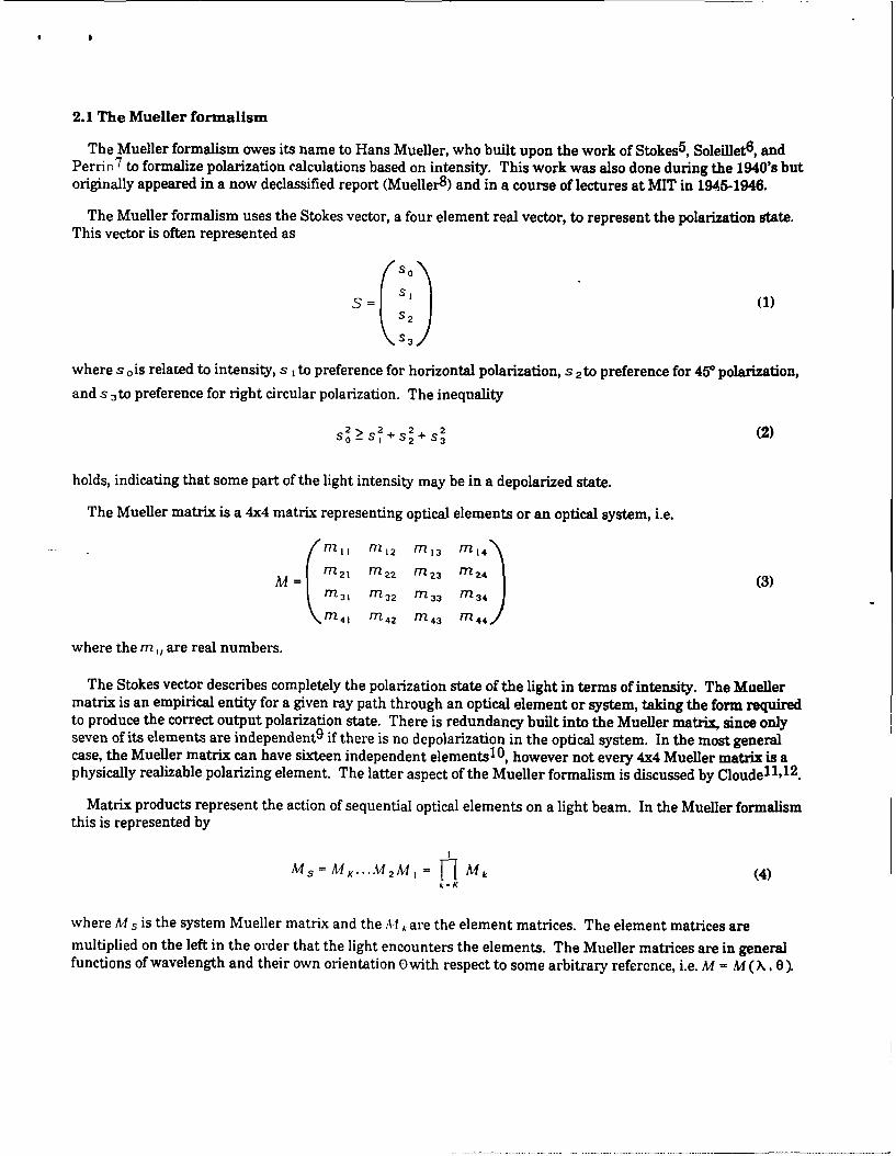
The Mueller formalism uses the Stokes vector, a four element real vector, to represent the polarization state.This vector is often represented as
so
- 3(1)
where s 0 is related to intensity, s I to preference for horizontal polarization, S 2 to preference for 450 polarization,
and s 3 to preference for right circular polarization. The inequality
2>S2+S2 + S2 (2)so- 1 2 S 3
holds, indicating that some part of the light intensity may be in a depolarized state.
The Mueller matrix is a 4x4 matrix representing optical elements or an optical system, i.e.
M I I M1 2 M I3 M 14
M = r 2, 2 2 m 2 3 Mn2 4 (3)Mn3 1 n 32 n 3 3 in 3 4 (
Mn 4 1 Mn 4 2 n 4 3 in 4 4 )/
where the m,, are real numbers.
The Stokes vector describes completely the polarization state of the light in terms of intensity. The Muellermatrix is an empirical entity for a given ray path through an optical element or system, taking the form requiredto produce the correct output polarization state. There is redundancy built into the Mueller matrix, since onlyseven of its elements are independent 9 if there is no depolarization in the optical system. In the most generalcase, the Mueller matrix can have sixteen independent elements 1 0 , however not every 4x4 Mueller matrix is aphysically realizable polarizing element. The latter aspect of the Mueller formalism is discussed by Cloude 1 1 ,12 .
Matrix products represent the action of sequential optical elements on a light beam. In the Mueller formalismthis is represented by
MS = K ... 42 M = Mk (4)k-K
where M s is the system Mueller matrix and the A" k are the element matrices. The element matrices aremultiplied on the left in the order that the light encounters the elements. The Mueller matrices are in generalfunctions of wavelength and their own orientation EO with respect to some arbitrary reference, i.e. M = M (X. 0).
The Mueller matrix can, unlike the Jones matrix, represent a depolarizer or scatterer, and van de Hulst10
describes this property. The Mueller matrix formalism has two advantages for experimental work over the Jonesformalism. The intensity is represented explicitly in the Mueller formalism, and scattering can be included in thecalculations.
2.2 Crystal physics
In general, crystals are anisotropic with respect to the propagation of electromagnetic waves in the presence ofstatic electric fields. The relationship between the displacement and the field is (MKS units)
D, = c, E / (5)
where E,, is the dielectric or permittivity tensor 13 . The impermeability tensor T, is defined as
1I, = Eo( - ) 1 (6)
where c - 'is the inverse of the dielectric tensor and E0 is the permittivity of free space. The principal indices of
refraction n x, n >, and n are related to the principal values of the impermeability tensor and the principal values
of the permittivity tensor by
11 0 o l (7)€f 117k Ck Ekk
The electrooptic coefficients are defined by the equation
r1,1 (E) - r,,(O)- Ail, = r,,kEk + SilEkE + O(E") (8)
where q,, is a function of the applied field E, r,,k are the linear electrooptic tensor or Pockels electrooptic
coefficients, and the s,,kare the quadratic or Kerr electrooptic coefficients. Terms higher than quadratic are
small and are neglected.
The linear electrooptic tensor is of third rank with 33 elements; however, symmetry enables a contraction. Ifthe medium is lossless and optically inactive, E ,, is a symmetric tensor, Tl,, is a symmetric tensor, r,,k has symme-
try where coefficients with permuted first and second indices are equal, and s, , has symmetry where coefficients
with permuted first and second indices are equal and coefficients with third and fourth coefficients are equal.The linear electrooptic coefficients are assigned two indices so that they are r ,k where I runs from 1 to 6 and k
runs from 1 to 3. The quadratic coefficients are assigned two indices so that they become s1 , where : runs from 1
to 6 andj runs from 1 to 6. For a given crystal symmetry class, the form of the electrooptic tenscr is availablefrom standard tables 1 3 .
Light propagating in anisotropic materials experiences refractive index and phase velocity dependent upon thepropagation direction and polarization state. The refractive index for propagation in some direction
= i + Y j+ z K can be obtained from the index ellipsoid. In the principal coordinate system the index ellipsoid
is given by
x2 2 2
2 2 2 (9). n'y nz
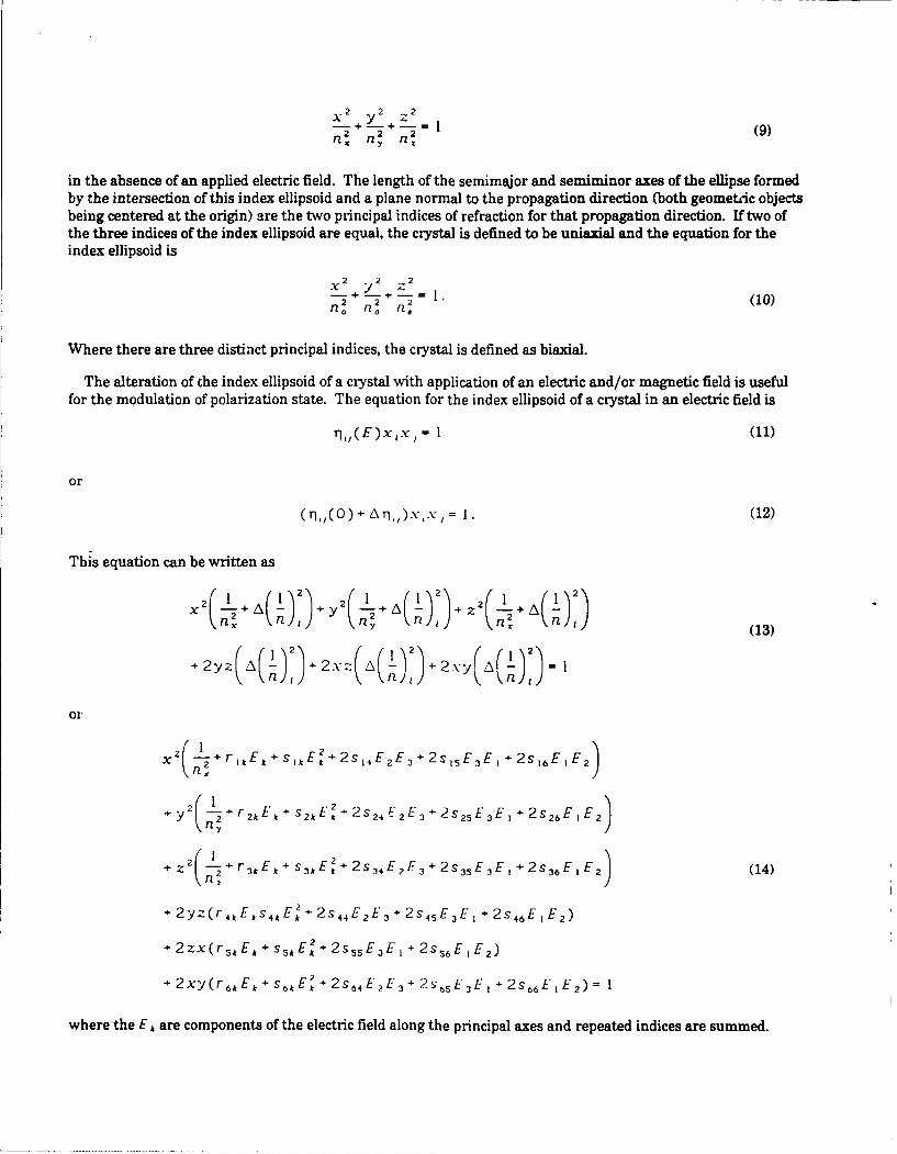
in the absence of an applied electric field. The length of the semimajor and semiminor axes of the ellipse formedby the intersection of this index ellipsoid and a plane normal to the propagation direction (both geometeic objectsbeing centered at the origin) are the two principal indices of refraction for that propagation direction. If two ofthe three indices of the index ellipsoid are equal, the crystal is defined to be uniaxial and the equation for theindex ellipsoid is
X2 2 -2+ +--= 1.
2 2 2(10)n. n. (1
Where there are three distinct principal indices, the crystal is defined as biaxial.
The alteration of the index ellipsoid of a crystal with application of an electric and/or magnetic field is usefulfor the modulation of polarization state. The equation for the index ellipsoid of a crystal in an electric field is
rl,,(E)xx, = l (11)
or
(q,,O)+Aq,).\'x, ].(12)
This equation can be written as
x2( 1 + ))+ Y2(+ )A))+Z2( + ))
n~EA ~f 2 n ns4 f~ 2 s 5 ff n+ 2sE nf 2
n y nZ (13)
+ 2 ( +rk A n , 2 + 2z A(4 n ~3+2 2 2.- y 2 n
X 2( .+ rIkEk + S3k E 2 2sI4E 2E3 + 2s 3E 3 E I+ 2s 6E I E 2
+ ,2(1
E 2 +2 +2 s3E,-- r2,E, + S2~ 224-E2 S 5E3 + 2s26E E 2
nZ-2-1 r 3kt E S*k3'E 2 + 2 s 34 E 2E3+2 s3 3s EE I + 2s36E I E2 (14)
+ 2yz(r 4kEks 4 kE' + 2s 4 fEzE 3 + 2s 45 E3 Ef + 2s 46 E IE 2 )
+ 2 zx(rSk-Ck + sSEA + 2s55E3E1 + 2s 6EF )
+2xy(r 6kf E+ s 6kEk +2s6 4 E2 E 3+ 2s6 sE 3 E F + 2s 6 6 E E2)= l
where the E, are components of the electric field along the principal axes and repeated indices are summed.
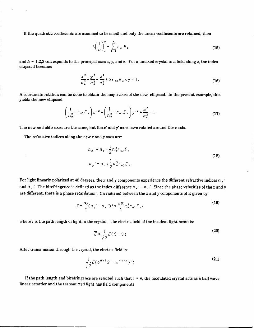
If the quadratic coefficients are assumed to be small and only the linear coefficients are retained, then
2 = r , E k(15)n k-1
and k = 1,2,3 corresponds to the principal axes x, y, and z. For a uniaxial crystal in a field along z, the indexellipsoid becomes
X2 y2 Z2
-+ -+ -+ 2r63 Exy= (16)no no n2
A coordinate rotation can be done to obtain the major axes of the new ellipsoid. In the present example, thisyields the new ellipsoid
(-+r E x2 + ( -r6E + = 1 (17)
The new and old z axes are the same, but the x' andy' axes have rotated around the z axis.
The refractive indices along the new x and y axes are:
n, =n,0 n 0 6 3 E
(18)
n = no+4 -nor 63EZ.
For light linearly polarized 't 45 degrees, the x andy components experience the different refractive indices ndyand n y The birefringence is defined as the index difference n Y" n,. Since the phase velocities of the x and y
are different, there is a phase retardation F (in radians) between the x and y components of E given by
UOn I . 2n (19)C X
where I is the path length of light in the crystal. The electric field of the incident light beam is:
E +(20)
After transmission through the crystal, the electric field is:
I 1 -r/ (21)
% 2
If the path length and birefringence are selected such that F = n, the modulated crystal acts as a half wavelinear retarder and the transmitted light has field components
1 -.2e -2 I__ E , . . , in2E()e " / e 1 )= x-e E )
F2 F2 (22)
= E--F--(k' - 9").
The axis of linear polarization of the incident beam has been rotated by 90 degrees by the phase retardation of n
radians or one-half wavelength. The incident linear polarization state has been rotated into the orthogonalpolarization state. An analyzer at the output end of the crystal aligned with the incident (or unmodulated) planeof polarization will block the modulated beam. For an arbitrary applied voltage producing a phase retardation ofF the analyzer transmits a fractional intensity co s 2 F. This is the principle of the Pockels cell.
3. POLARIMETRY
Polarimetry, or transmission ellipsometry, is the branch of ellipsometry concerned with measuring the polar-ization state of a light beam and deducing the polarizing properties of bulk materials. A polarimeter is an opticalinstrument used for the determination of the polarization state of a light beam. Given the knowledge of how thepolarimeter itself acts on the light, the polarization change produced by inserting a bulk sample into the polari-meter may be determined. Implementation of polarimetry can be identical to ellipsometry except that the opticalpath goes completely through the sample.
The infrared laser polarimeter described here is designed to be operated over the 3 to 14 pm spectral region
using laser sources at several wavelengths. This spectral region is of great interest for evaluation of materialsused as elements of optical processing systems or thermal imaging systems.
The optical configuration used is called the dual rotating compensator ellipsometer when it is used in ellip-sometry. The data processing prescription which accompanies these optics has been described by Azzam 1 4 andby Hauge 1 5 . This polarimeter uses two fixed polarizers and two rotating waveplates in a configuration discussedbelow. Mueller matrix elements and Stokes vectors are used here to represent the polarization elements andpolarized light, respectively. The Mueller matrix formulation is used because it is preferable for experimentalwork where scattering and depolarization measurements are required. Two waveplates are rotated at differentbut harmonic rates and a modulation of the detected intensity results. The Mueller matrix of the sample is foundthrough a relationship between the Fourier coefficients of a series representing the modulation and the elementsof the sample matrix.
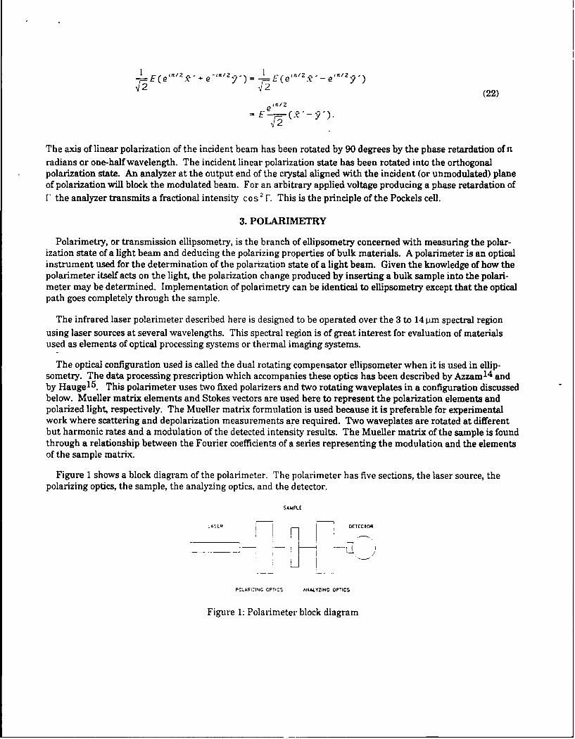
Figure 1 shows a block diagram of the polarimeter. The polarimeter has five sections, the laser source, the
polarizing optics, the sample, the analyzing optics, and the detector.
SAMPLE
,ASR DEOTECTOR
POLARIZING OPTICS ANALYZING OPTICS
Figure 1: Polarimeter block diagram
The polarizing optics consist of a polarizer and a quarter wave plate both mounted in computer controlledrotating stages. The sample region is followed by the analyzing optics which consist of a quarter wave plate in acomputer controlled rotating stage followed by a polarizer. Polarization sensitivity of the detector is not impor-tant since the orientation of the final polarizer does not change.
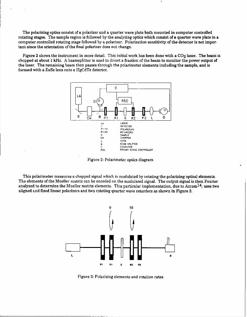
Figure 2 shows the instrument in more detail. This initial work has been done with a CO 2 laser. The beam ischopped at about 1 kHz. A beamsplitter is used to divert a fraction of the beam to monitor the power output ofthe laser. The remaining beam then passes through the polarimeter elements including the sample, and isfocused with a ZnSe lens onto a HgCdTe detector.
CH P1 R1 S R2 P2 L D
LA LASER0 DETECTOR
P; JP2 POLARIZERSR I R2 RETARDERS
S SAMPLECH CHOPPER
L LENSB BEAM SPLITTERC COMPUTER
RSC ROTARY STAGE CONTROLLER
Figure 2: Polarimeter optics diagram
This polarimeter measures a chopped signal which is modulated by rotating the polarizing optical elements.The elements of the Mueller matrix can be encoded on the modulated signal. The output signal is then Fourieranalyzed to determine the Mueller matrix elements. This particular implementation, due to Azzam 14 , uses twoaligned and fixed linear polarizers and two rotating quarter wave retarders as shown in Figure 3.
o 50
PI RI S R2 P2
Figure 3: Polarizing elements and rotation rates
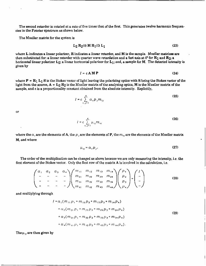
The second retarder is rotated at a rate of five times that of the first. This generates twelve harmonic frequen-
cies in the Fourier spectrum as shown below.
The Mueller matrix for the system is
L2 R 2 (() M Rj(O) L1 (23)
where L indicates a linear polarizer, R indicates a linear retarder, and M is the sample. Mueller matrices arethen substituted for: a linear retarder with quarter wave retardation and a fast axis at 0 for R1 and R 2 ; ahorizontal linear polarizer L2 ; a linear horizontal polarizer for Li; and, a sample for M. The detected intensity isgiven by
I= cAMP (24)
where P = R1 L1 S is the Stokes vector of light leaving the polarizing optics with S being the Stokes vector of thelight from the source, A = L2 R2 is the Mueller matrix of the analyzingoptics, M is the Mueller matrix of thesample, and c is a proportionality constant obtained from the absolute intensity. Explicitly,
4 (25)/ =C Uaplml,',1-I
or
4 (26)= c Ll /
where the a, are the elements of A, the p , are the elements of P, the m,, are the elements of the Mueller matrix
M, and where
tl = appI. (27)
The order of the multiplication can be changed as above because we are only measuring the intensity, i.e. thefirst element of the Stokes vector. Only the first row of the matrix A is involved in the calculation, i.e.
a, a2 a,3 174 n, Mn1 2 Mn, 3 rn 4 P I
n' - M 22 M 23 M 24 P 2 (28)M 31 i 7- 32 in 3 3 7-34 p 3
- 741 I 14 2 in 4 3 in 4 4 (p 4
and multiplying through
I =aI (m P + I ,M 2 p 2 + t 3 p 3 + m4P 4 )
+ cU2 (m 2 1 P + M 2 2 P 2 + rTZ 2 3 P 3 + m 2 4 P 4 )
(29)+ a3(M31P + M32P2 + M33P 3 + m34P 4 )
+ c"4 (r ,, P1 + i' .,2 P+ '') 2-43P3+ /n 4 4 P 4 ).
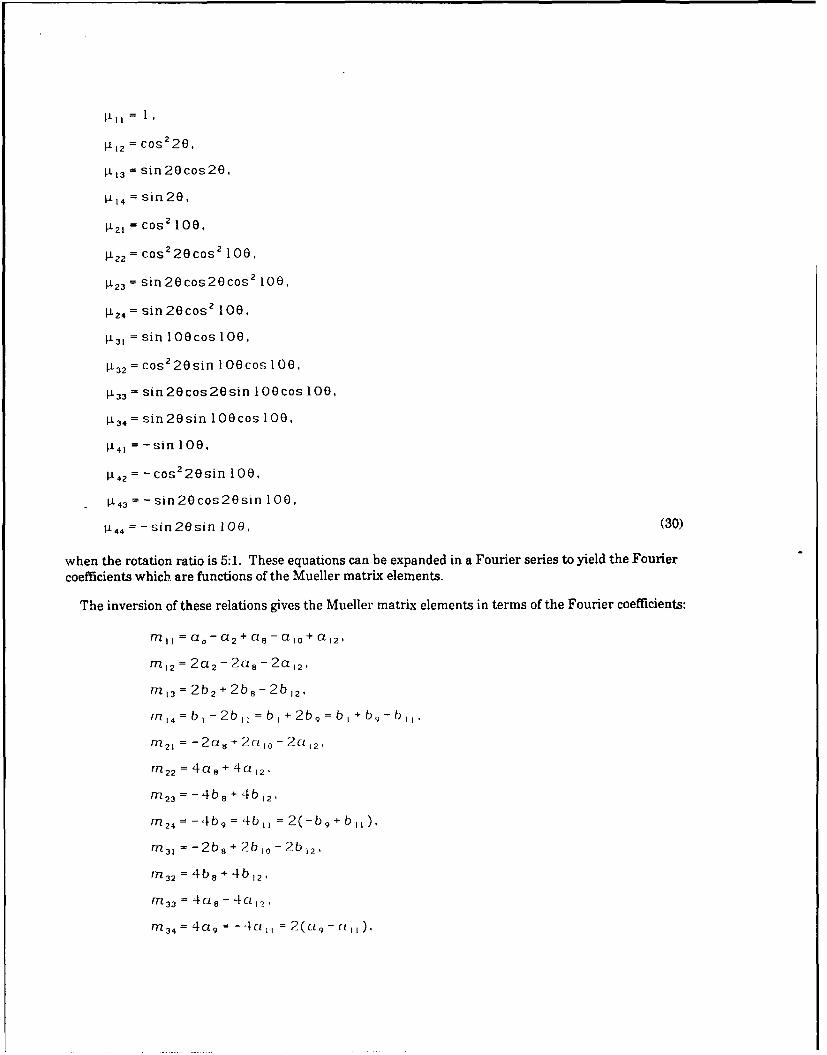
The V,, are then given by
2l = cos2 20,
1i3 = sin 20cos20,
P1 4 = sin 20,
112 1 = Cos 100,
P 22 = cos220cos2 100,
I 23 =sin 2Ocos20cos 2 100,
1L24 = sin 20cos 2 100,
[i, = sin lOOcos 100,
1P32 = cos 2 20sin 100cos 100,
11 33 = sin20cos20sin 10 cos 100,
,3 4= sin 20sin lOecos 100,
i4, =-sin 100,
[L4 = -cos 2 20sin 100,
1i 4= =-sin 20cos20sin 100,
i4 4 = -sin 20sin 100, (30)
when the rotation ratio is 5:1. These equations can be expanded in a Fourier series to yield the Fourier
coefficients which are functions of the Mueller matrix elements.
The inversion of these relations gives the Mueller matrix elements in terms of the Fourier coefficients:
M = CLo - a 2 + ct, - a1o+ a 12,
m 2 = 2a 2 - 2a - 2a 2,
m 3 = 2b 2 + 2b3- 2b, 2 ,
M 4 = b - 2bII = b + 2b, = b +b, - b,
MT2 1 = -2u, + 2ct 1o - 2ct 12,
rnT2 2 = 4a 5 .+ 4a12 ,
Mn 2 3 = -4b, + 4b 12,
rn 2 4 =-4bg= 4b, = 2(-b 9+ bII),
i 3, = -2b, + 2b, - 2b 1 2 ,
rn 3 2 = 4b 8 + 4b 12,
in 33 = 4u 8 - CI? 1'
in 3 4 = 4a 9 = - 4u, = 2(c- ,),
m,= 2b 3 -b 5 =-b 5 + 2b 7 = (b 3 -b 5 + b7 ),
M42 = -4b = -4b 7 = -2(b 3 + b,),
n 4 3 = -4a 3 = 4a 7 = 2(-a 3 + a,),
M 4 = -2a 4 = 2a 6 = (a 6 - a 4 ). (31)
The 5:1 rotation ratio is not the only ratio which can be used to determine Mueller matrix elements, but it is the
lowest ratio where the expressions for the Fourier coefficients may be inverted.
4. SPECTROPOLARIMETRY
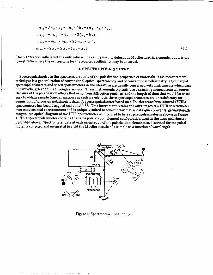
Spectropolarimetry is the spectroscopic study of the polarization properties of materials. This measurementtechnique is a generalization of conventional optical spectroscopy and of conventional polarimetry. Commercialspectropolarimeters and spectropolarimeters in the literature are usually concerned with instruments which passone wavelength at a time through a sample. These instruments typically use a scanning monochrometer source.Because of the polarization effects that arise from diffraction gratings, and the length of time that would be n--ces-sary to obtain sample Mueller matrices at each wavelength, these spectropolarimeters are unsatisfactory foracquisition of precision polarimetric data. A spectropolarimeter based on a Fourier transform infrared (FTIR)spectrometer has been designed and built16,17. This instrument retains the advantages of a FTIR spectrometerover conventional spectrometers and is uniquely suited to collect polarimetric data quicldy over large wavelengthranges. An optical diagram of trie FTIR spectrometer as modified to be a spectropolarimeter is shown in Figure4. This spectropolarimeter contains the same polarization element configuration used in the laser polarimeterdescribed above. Spectrometer data at each orientation of the polarization elements as described for the polari-meter is collected and integrated to yield the Mueller matrix of a sample as a function of wavelength.
MS M
MFM2
i u 4D
Figure 4: Spectropclietroic
5. MEASUREMENT OF ELECTROOPTIC COEFFICIENTS
The goal of this work is to obtain electrooptic coefficients from Mueller matrices. The method by which this isaccomplished in described in this section.
The application of an electric field across a crystal produces an index change as described. Specific indexchanges for a sample material is best presented in tabular form. Table 1 gives the index ellipsoid and the indicesalong the new principal axes. The new principal indices are obtained by solving an eigenvalue problem. Forexample, for a cubic material with a field perpendicular to the (1 11 ) plane, the index ellipsoid is
x 2 +y 2 +z 2 2 (32)+ r E(yz+zx+xy)=l1n2 F4
and the eigenvalue problem is
1 2r 4 1 E 2r 4 1 E
2'2r , E 1 2r4,l E 1 (33)
2r 4 1 E 2r 41 E 12
F3 F3 no
The secular equation is then
I I 2r 4 E 2r 4 ,E
2r 4 1 E 1 2r 4 1 E (34)~ 2 -2F3 no n' F
2r 4 1 E 2r 4 1 E 1 1
V3 no '2
and the roots of this equation are the new principal indices.
The phase retardation accumulated by polarized light in traversing a medium with anisotropic properties isgiven by
F = 21t(n. - nb)L/X (35)
where L is the medium thickness in the direction of propagation, X is the wavelength of light, and n ,, n bare theindices experienced in two orthogonal directions perpendicular to the direction of propagation. In the longitudi-nal mode of operation, the electric field and propagation direction are both along the z axis. The refractive indicesexperienced by the light are in the plane containing the x and y principal axes. If the light polarization andcrstal are aligned so that the polarization is 450 from either principal axis, the phase retardation will be
F = 21t(n - n ')L/X (36)
where n,', n 'are the (new) principal indices with the field applied. (For crystals with natural birefringence and
with no electric field, these indices may just be the principal indices.)
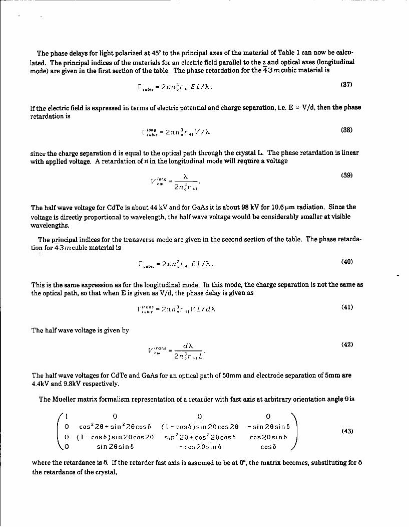
The phase delays for light polarized at 450 to the principal axes of the material of Table I can now be calcu-
lated. The principal indices of the materials for an electric field parallel to the z and optical axes (longitudinalmode) are given in the first section of the table. The phase retardation for the 43mcubic material is
F cbic = 2nnor4 1 EL/X. (37)
If the electric field is expressed in terms of electric potential and charge separation, i.e. E = V/d, then the phase
retardation is
F"" = 2Ttn 3 r4 V iX (38)cubic0
since the charge separation d is equal to the optical path through the crystal L. The phase retardation is linearwith applied voltage. A retardation of n in the longitudinal mode will require a voltage
V long = X (39)hW 2nor 4
(
The half wave voltage for CdTe is about 44 kV and for GaAs it is about 98 kV for 10.6 pm radiation. Since the
voltage is directly proportional to wavelength, the half wave voltage would be considerably smaller at visiblewavelengths.
The principal indices for the transverse mode are given in the second section of the table. The phase retarda-tion for 4 3 m cubic material is
Fcubic = 2 nor 4' EL/X. (40)
This is the same expression as for the longitudinal mode. In this mode, the charge separation is not the same asthe optical path, so that when E is given as V/d, the phase delay is given as
F .rr.s = 32n orE LIds (41)cubic =2nr I/Ld
The half wave voltage is given by
v frans d k (42)Vhw 2 n r L
The half wave voltages for CdTe and GaAs for an optical path of 50mm and electrode separation of 5mm are
4.4kV and 9.8kV respectively.
The Mueller matrix formalism representation of a retarder with fast axis at arbitrary orientation angle e is
(1 0 0
00 cos2 20+sin 2 20cosb (I -cos6)sin2Ocos20 -sin2Osin6 (43)
w (I - cosb)sin 20cos2O sin 2 20+ cos 2 20cos6 cos20sinb
sin20sin6 -cos2Osinb cos6
where the retardance is a If the retarder fast axis is assumed to be at 00, the matrix becomes, substituting for 6
the retardance of the crystal,
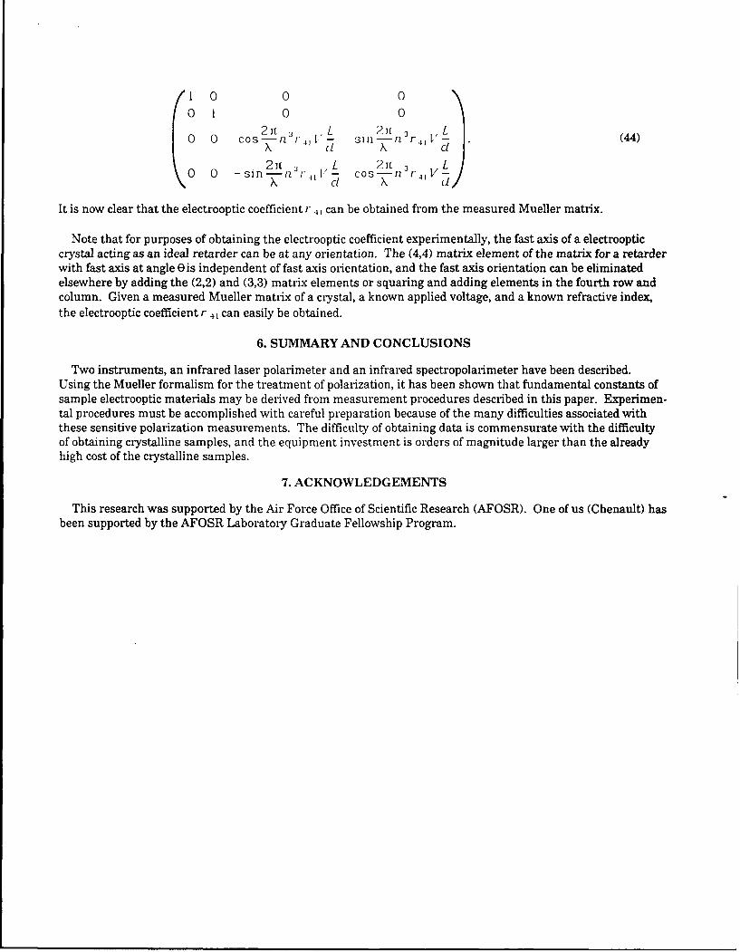
0 1 0 0
0 0 Cos21n 3r I'L sill 2 (44)X C1 X d
0 0 -sin2 it nr 1 L Cos21tn 3r L
It is now clear that the electrooptic coefficient r can be obtained from the measured Mueller matrix.
Note that for purposes of obtaining the electrooptic coefficient experimentally, the fast axis of a electroopticcrystal acting as an ideal retarder can be at any orientation. The (4,4) matrix element of the matrix for a retarderwith fast axis at angle e is independent of fast axis orientation, and the fast axis orientation can be eliminatedelsewhere by adding the (2,2) and (3,3) matrix elements or squaring and adding elements in the fourth row andcolumn. Given a measured Mueller matrix of a crystal, a known applied voltage, and a known refractive index,the electrooptic coefficient r 4I can easily be obtained.
6. SUMMARY AND CONCLUSIONS
Two instruments, an infrared laser polarimeter and an infrared spectropolarimeter have been described.Using the Mueller formalism for the treatment of polarization, it has been shown that fundamental constants ofsample electrooptic materials may be derived from measurement procedures described in this paper. Experimen-tal procedures must be accomplished with careful preparation because of the many difficulties associated withthese sensitive polarization measurements. The difficulty of obtaining data is commensurate with the difficultyof obtaining crystalline samples, and the equipment investment is orders of magnitude larger than the alreadyhigh cost of the crystalline samples.
7. ACKNOWLEDGEMENTS
This research was supported by the Air Force Office of Scientific Research (AFOSR). One of us (Chenault) hasbeen supported by the AFOSR Laboratory Graduate Fellowship Program.
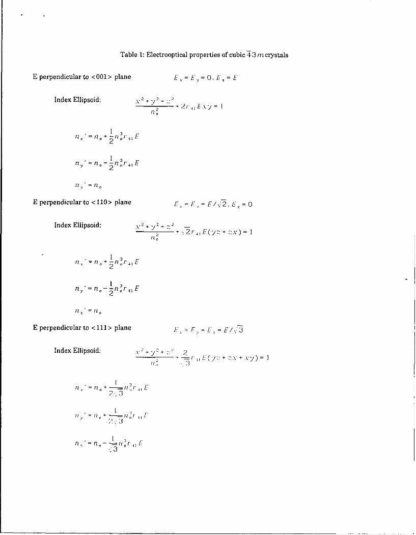
Table 1: Electrooptical properties of cubic 43 m crystals
E perpendicular to <001 > plane L--. = E = 0, E = E
Index Ellipsoid: 2 + Y 2 + 2
2 2r 4 ExY= I
n2 n o + I n 3 r,,f2 0
13
n1 = 0 -- nOr 4 1 EFny n, - 2n 3
0r
fl: =n0~
E perpendicular to <110> plane E = E 2, E z 0
Index Ellipsoid: 2 2 + 2
n, n,-- r-,'2,,(E -=x2
1 3nix. =~ n+ -o 4 1 E
2 l
n-: = FZo
E perpendicular to <111> plane = E.
Index Ellipsoid: 2 + >/2 + 2 22 + -r + + -y) =
3?
3
2>313n=n0 --- = _ r r, i
8. REFERENCES
1. A. Gerrard and J.M. Burch, Introduction to Matrix Methods in Optics, Wiley, London, 1975.
2. R.M.A. Azzam and N.M. Bashara, Ellipsometry and Polarized Light North-Holland Publishing Company,Amsterdam, 1977.
3. D. Clarke and J.F. Grainger, Polarized Light and Optical Measurement, Pergamon Press, Oxford, 1971.
4. P.S. Theocaris and E.E. Gdoutos, Matrix Theory of Photoelasticity, Springer-Verlag, Berlin 1979.
5. G.G. Stokes, "On the composition and resolution of streams of polarized light from different sources," Trans.Cambridge Phil. Soc., Vol. 9, p. 399, 1852.
6. P. Soleillet, "Sur les parametres caracterisant la polarisation partielle de la lumiere dans les phenomenes defluorescence," Ann. Phys., Vol. 12, p. 23, 1929.
7. F. Perrin, "Polarization of light scattered by isotropic opalescent media," J. Chem. Phys., Vol. 10, p. 415,1942.
8. H. Mueller, "Memorandum on the polarization optics of the photoelastic shutter," Report No. 2 of the OSRDproject OEMsr-576, Nov. 15, 1943.
9. W. Shurcliff, Polarized Light, Oxford University Press, London, 1962.
10. H.C. van de Hulst, Light Scattering by Small Particles, Dover, New York, 1981.
I1. S.R. Cloude, "Group theory and polarisation algebra," Optik, Vol. 75, pp. 26-36, 1986.
12. S.R. Cloude, "Conditioning for physical reliability of matrix descriptions in polarimetry," in PolarizationConsiderations for Optical Systems II, Proc. SPIE, Vol. 1166, pp. 177-185, ed. Chipman, August 1989.
13. A. Yariv and P. Yeh, Optical Waves in Crystals, Wiley, New York, 1984.
14. R.M.A. Azzam, "Photopolarimetric measurement of the Mueller matrix by Fourier analysis of a singledetected signal," Opt. Lett., Vol. 2, No. 6, pp. 148-150, June 1978.
15. P.S. Hauge, "Mueller matrix ellipsometi y with imperfect compensators," J. Opt. Soc. Am., Vol. 68, No. 11,pp. 1519-1528, November 1978.
16. D.H. Goldstein, R.A. Chipman, and D.B. Chenault, "Infrared Spectropolarimety," Opt. Eng., Vol. 28, No. 2,pp. 120-125, February 1989.
17. D.B. Chenault and R.C. Chipman, Infrared Spectropolarimetry," in Polarization Considerations for OpticalSystems II, Proc. SPIE, Vol. 1166, pp. 254-266, ed. Chipman, August 1989.

![Degree of Polarization the Lyot Depolarizer · BURNS: DEGREE OF POLARIZATION IN THE LYOT DEPOLARIZER 477 Sl(z) = 8rJm Iv(w)12 cos [(a - o0)Srgz] dw. (8b) To derive (7) and (8), we](https://static.fdocuments.net/doc/165x107/60779294dfca6232982a9800/degree-of-polarization-the-lyot-depolarizer-burns-degree-of-polarization-in-the.jpg)