JUMO DELOS T
13
V2.00/EN/00536576 Page 1/13 Data Sheet 902940 90294000T10Z001K000 JUMO DELOS T Electronic temperature switch with display and analog output Application • Food and pharmaceutical • CIP/SIP plants • Mechanical and plant engineering • Air conditioning and refrigeration applications Brief description The highly-precise, electronic temperature switch consists of a protection tube with built-in tem- perature sensor, a process connection, and attached housing with LCD display for the electron- ics. Depending on the application, the following output variants are available: 1× PNP or 2× PNP switching output (binary output) or 1× PNP switching output and 1× analog output. The configu- ration of the output signal and the measuring range can be customized. Depending on the ver- sion, the electronic temperature switch can be used in an operating temperature range from - 50 to +150 °C, -50 to +260 °C, and -50 to +500 °C. The analog output signal 4 to 20 mA, 0 to 20 mA, 0 to 10 V or reversed 20 to 4 mA, 20 to 0 mA, and 10 to 0 V is available in a linear- ized fashion (temperature linear). The electronic temperature switch is designed for industrial use and complies with the European standards to guarantee electromagnetic compatibility (EMC). Note: also available as JUMO DELOS SI and HP – precision pressure transmitter with switching contacts and display, see data sheet 405052 and data sheet 405054. Basic type 902940/10 Block diagram DELOS T Temperature Voltage supply DC 12(14) to 30 V Interface Setup program LCD display 2× 4 characters, 2-color Switching output 1 Open-collector Max. 250 mA Shaft encoder Operation: turn and press Switching output 2 Open-collector Max. 250 mA Option Analog output 0(4) 20 mA or 0 to 10 V to or Special features • For temperatures from -50 to +260 °C (500 °C) • Hygienic process connection • Configuration performed with the rotary encoder on the temperature switch or setup program • M12 × 1 plug connection; protection type IP67 according to DIN EN 60529 with pushed in machine connector • Positively lit LCD display
Transcript of JUMO DELOS T

Page 1/13Data Sheet 902940
JUMO DELOS TElectronic temperature switch with display and analog output
Application• Food and pharmaceutical• CIP/SIP plants• Mechanical and plant engineering• Air conditioning and refrigeration applications
Brief descriptionThe highly-precise, electronic temperature switch consists of a protection tube with built-in tem-perature sensor, a process connection, and attached housing with LCD display for the electron-ics. Depending on the application, the following output variants are available: 1× PNP or 2× PNPswitching output (binary output) or 1× PNP switching output and 1× analog output. The configu-ration of the output signal and the measuring range can be customized. Depending on the ver-sion, the electronic temperature switch can be used in an operating temperature range from -50 to +150 °C, -50 to +260 °C, and -50 to +500 °C. The analog output signal 4 to 20 mA,0 to 20 mA, 0 to 10 V or reversed 20 to 4 mA, 20 to 0 mA, and 10 to 0 V is available in a linear-ized fashion (temperature linear). The electronic temperature switch is designed for industrialuse and complies with the European standards to guarantee electromagnetic compatibility(EMC).
Note: also available as JUMO DELOS SI and HP – precision pressure transmitter with switchingcontacts and display, see data sheet 405052 and data sheet 405054.
V2.00/EN/00536576
Basic type 902940/10
Block diagram
DE
LO
S T
Temperature
Voltage supply
DC 12(14) to 30 V
Interface
Setup program
LCD display
2× 4 characters, 2-color
Switching output 1
Open-collector
Max. 250 mA
Shaft encoder
Operation: turn and press
Switching output 2
Open-collector
Max. 250 mA
Option
Analog output
0(4) 20 mA or 0 to 10 Vto
or
Special features• For temperatures from -50 to +260 °C
(500 °C)• Hygienic process connection• Configuration performed with the rotary
encoder on the temperature switch orsetup program
• M12 × 1 plug connection;protection type IP67 according to DIN EN60529with pushed in machine connector
• Positively lit LCD display
90294000T10Z001K000
Page 2/13Data Sheet 902940
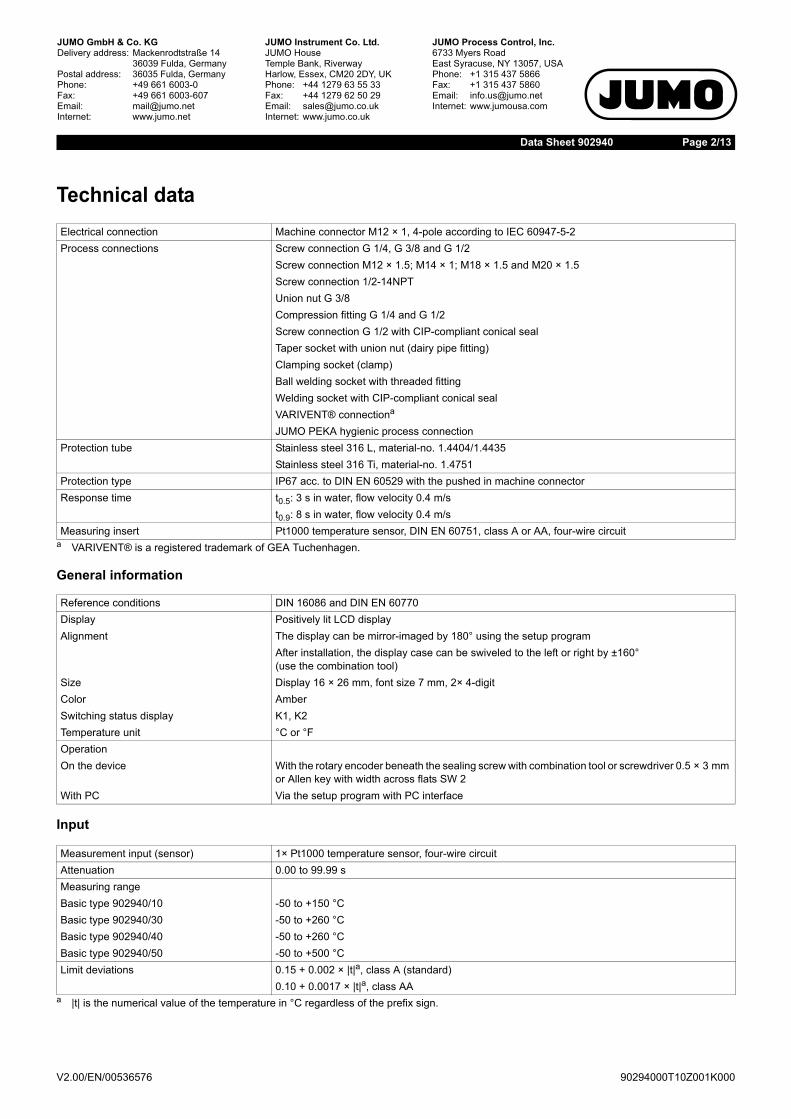
Technical data
General information
Input
Electrical connection Machine connector M12 × 1, 4-pole according to IEC 60947-5-2Process connections Screw connection G 1/4, G 3/8 and G 1/2
Screw connection M12 × 1.5; M14 × 1; M18 × 1.5 and M20 × 1.5Screw connection 1/2-14NPTUnion nut G 3/8Compression fitting G 1/4 and G 1/2Screw connection G 1/2 with CIP-compliant conical sealTaper socket with union nut (dairy pipe fitting)Clamping socket (clamp)Ball welding socket with threaded fittingWelding socket with CIP-compliant conical sealVARIVENT® connectiona
a VARIVENT® is a registered trademark of GEA Tuchenhagen.
JUMO PEKA hygienic process connectionProtection tube Stainless steel 316 L, material-no. 1.4404/1.4435
Stainless steel 316 Ti, material-no. 1.4751Protection type IP67 acc. to DIN EN 60529 with the pushed in machine connectorResponse time t0.5: 3 s in water, flow velocity 0.4 m/s
t0.9: 8 s in water, flow velocity 0.4 m/sMeasuring insert Pt1000 temperature sensor, DIN EN 60751, class A or AA, four-wire circuit
Reference conditions DIN 16086 and DIN EN 60770Display Positively lit LCD displayAlignment The display can be mirror-imaged by 180° using the setup program
After installation, the display case can be swiveled to the left or right by ±160°(use the combination tool)
Size Display 16 × 26 mm, font size 7 mm, 2× 4-digitColor AmberSwitching status display K1, K2Temperature unit °C or °FOperationOn the device With the rotary encoder beneath the sealing screw with combination tool or screwdriver 0.5 × 3 mm
or Allen key with width across flats SW 2With PC Via the setup program with PC interface
Measurement input (sensor) 1× Pt1000 temperature sensor, four-wire circuitAttenuation 0.00 to 99.99 sMeasuring rangeBasic type 902940/10 -50 to +150 °CBasic type 902940/30 -50 to +260 °CBasic type 902940/40 -50 to +260 °CBasic type 902940/50 -50 to +500 °CLimit deviations 0.15 + 0.002 × |t|a, class A (standard)
0.10 + 0.0017 × |t|a, class AAa |t| is the numerical value of the temperature in °C regardless of the prefix sign.
V2.00/EN/00536576 90294000T10Z001K000

Page 3/13Data Sheet 902940
Measuring circuit monitoring
OutputsAll analog outputs in three-wire circuit, open collector, PNP switching output
Probe short circuit,probe/cable break,underrange,overrange
Analog output 0 to 20 mA, 0 mA or 22 mA user configurableAnalog output 4 to 20 mA, 3.4 mA or 22 mA user configurableAnalog output 0 to 10 V, 0 V or 10.7 V user configurableSwitching outputs, lowAdditional error message via the LCD display
Analog outputUser configurable 4 to 20 mA and 1× PNP switching output
0 to 20 mA and 1× PNP switching output0 to 10 V and 1× PNP switching output
Switching outputNumber 1× PNP switching output
2× PNP switching outputSwitching type N/C contact / N/O contactSwitching function Window/hysteresisContact ratingVoltage drop from UB PNP ≤ 2 VSwitching capacity On ≤ 250 mA; off ≤ 1 mASwitching cycles > 10 millionResponse timeAt 50 Hz ≤ 200 msAt 60 Hz ≤ 320 msShort-circuit proof YesLoad check, currentPulse period 2 s; TON 40 msPeriodic protective circuitfor overcurrent
f = 0.5 HzLCD display: Err3 switching output K1, Err4 switching output K2
Scaling rangeAnalog output Scaling can be freely selected within the measuring rangeBehavior when leaving the scalingarea (underrange)
Analog output 0 to 20 mA, linear drop up to 0 mAAnalog output 4 to 20 mA, linear drop up to 3.8 mAAnalog output 0 to 10 V, linear drop up to 0 V
Behavior when leaving the scalingarea (overrange)
Analog output 0 to 20 mA, linear rise up to 20.5 mAAnalog output 4 to 20 mA, linear rise up to 20.5 mAAnalog output 0 to 10 V, linear rise up to 10.2 V
Switching outputSwitching point Measuring range ( > release point)Release point Measuring range ( < switching point)Switching delay 0.00 to 99.99 sBurden4 to 20 mA RI ≥ (UB - 6.5 V) ÷ 0.022 A0 to 20 mA RI ≥ (UB - 6.5 V) ÷ 0.022 A0 to 10 V R ≥ 10 kΩ
V2.00/EN/00536576 90294000T10Z001K000

Page 4/13Data Sheet 902940
Environmental influences
Accuracy of entire device
Auxiliary energy
Admissible temperaturesAmbient temperature, display case -25 to +75 °CAmbient temperature -50 °C; restricted function
only stationary use, risk of cable break, LCD display without functionStorage temperature -40 to +85 °CAdmissible humidityDuring operation 100 % including condensation on the device outer caseIn storage 90 % without condensationAdmissible mechanical load Referring to basic type 902940/10, 902940/30 and 902940/40 with insertion length 100 mmVibration resistance 10 g, 10 to 2000 Hz according to IEC 60068-2-6Shock resistance 50 g for 11 ms / 100 g for 1 ms according to IEC 60068-2-27Electromagnetic compatibility (Only with 4-pole connecting cable and grounded housing)Interference emission Class A according to EN 61326Interference immunity Performance characteristic A according to EN 61326Protection type IP67 according to DIN EN 60529Ambient temperature influence ≤ ±(15 ppm/K × (measuring range end value + 200) + 50 ppm/K × configured measuring range) ×
ΔϑΔϑ = deviation of the ambient temperature from the reference temperature
Calibration/reference conditions DC 24 V at 25 °C ±5 °C (77 °F ±9 °F)
Measured value Tolerance100 °C 0.60 K150 °C 0.75 K200 °C 1.00 K450 °C 1.60 K
Voltage supply DC 12 to 30 V (nominal voltage supply DC 24 V)Residual ripple: ensure that the voltage peaks do not exceed or fall below the specified values for the voltage supply
For output 0(4) to 20 mA DC 12 to 30 VFor output 0 to 10 V DC 14 to 30 VReverse voltage protection YesPower consumption ≤ 45 mA without load, ≤ 545 mA with load 2× PNP switching outputElectrical connection Machine connector M12 × 1, 4-pole according to IEC 60947-5-2, A-codedElectrical circuit SELVInfluence of the voltage supply ≤ ±0.01 % per V deviation from DC 24 Va
a %-specifications refer to the measuring range end value of 20 mA/10 V.
V2.00/EN/00536576 90294000T10Z001K000

Page 5/13Data Sheet 902940
Connection diagramThe connection diagram in the data sheet provides preliminary information about the connection options. For the electrical connection, only usethe installation instructions or the operating manual. The knowledge and the correct technical compliance with the safety information and warningscontained in these documents are mandatory for mounting, electrical connection, and startup as well as for safety during operation.
The connection is located on the rear of the temperature switch!
Connection diagram (sensor)
Order code 470 Order code 471 Order codes 475, 476, and 4771× PNP switching output 2× PNP switching output 1× PNP switching output
and 1× analog output
Voltage supply
Voltagesupply
Voltagesupply
1 L+ DC 12 to 30 V 1 L+ DC 12 to 30 V 1 L+ DC 12(14) to 30 V3 L- GND 3 L- GND 3 L- GNDOutput Output Output
4 K1 Highside open collectormax. 0.25 A
2 K2 Highside open collectormax. 0.25 A
2 analog 0(4) to 20 mA/0 to 10 V
2 nc 4 K1 4 K1 Highside open collectormax. 0.25 A
5 Interface 5 Interface 5 Interface
1
2
3
4
5
L-K1
L+
1
2
3
4
5
L-K1 K2
L+
1
2
3
4
5
L-K1
L+
Color coding: connecting cable round plug M12 × 1 1 BN Brown2 WH White3 BU Blue4 BK Black5 GY Grey
The color coding is only for A-coded standard cables!
Machine connector M12 × 1, 4-pole according to IEC 60947-5-2
Electrical connection Terminal assignment
Basic type 902940/50RTD temperature probe in four-wire circuit(input)
Top view of the machine connector at the cor-responding RTD temperature probe!
1 2 3
�
4
V2.00/EN/00536576 90294000T10Z001K000

Page 6/13Data Sheet 902940
DimensionsBasic types
Basic type 902940/10 Basic type 902940/30with extension tube
Basic type 902940/40with adaption system for thermowell 902812/10
Basic type 902940/50with M12 × 1 plug connectionfor RTD temperature probes
Ø 42
7530
G
EL
D
M12
× 1
app
rox.
25
35
Ø 42
30
35
M12
× 1
75
app
rox.
70
G
EL
D
Ø 3
EL
67
12
0
30
M1
2 ×
1
Ø 42
M14 × 1
M12 × 1
75
20
30
Ø 20
35
M12
× 1
Ø 42
35
V2.00/EN/00536576 90294000T10Z001K000

Page 7/13Data Sheet 902940
Process connections PA
PA G PA103 3/8 380104 1/2Screw connection Screw connection with CIP-compliant conical seal
PA DN D1 PA DN D1 PA- - Ø 25 613 40/1.5” Ø 50.5 681611 10/20 Ø 34 616 50/2” Ø 64613 25/1” Ø 50.5 617 2.5” Ø 77.5Clamping socket according to DIN 32676 (clamp) Ball welding socket with threaded fitting
V2.00/EN/00536576 90294000T10Z001K000

Page 8/13Data Sheet 902940
PA DN D1 D2 D3 D4 L1 L2 PA601 10 Ø 22 Ø 18 RD 28 × 1/8 Ø 38 9 18 682604 25 Ø 44 Ø 35 RD 52 × 1/6 Ø 63 13 21605 32 Ø 50 Ø 41 RD 58 × 1/6 Ø 70 13 21Clamping socket with union nut acc. to DIN 11851(dairy pipe fitting)
Welding socket with CIP-compliant conical seal
28EL
1541
D
30Ø
G1/2
18Ø
PA DN D1 PA684 15/10 Ø 31 840685 32/25 Ø 50686 50/40 Ø 68VARIVENT® connection Ball welding sleeve
V2.00/EN/00536576 90294000T10Z001K000

Page 9/13Data Sheet 902940
VARIVENT® Clamp Aseptic Welding socketDN 25/32 DN 25/32/40 DN 40 Ø 55 mmDN 40-125 DN 50 DN 50 -- - NKS DN 40 -JUMO PEKA PA 997Process connection adapter, data sheet 409711
V2.00/EN/00536576 90294000T10Z001K000

Page 10/13Data Sheet 902940
Setup programThe setup program (accessories) is used to configure the temperature switch with a PC.The configuration data can be archived and printed on the PC.
The setup program can be used to overwrite changed parameters with the factory setting at anytime.The connection between temperature switch and PC is established using a PC interface (USB/TTL converter) with adapter (USB connecting cable) and transmitter cable (Y cable).
V2.00/EN/00536576
90294000T10Z001K000
Page 11/13Data Sheet 902940
Order details(1) Basic typea
902940/10 DELOS T – Electronic temperature switchwith display and analog outputParts coming into contact with the medium are electrolytically pol-ished,surface roughness ≤ 0.8 μm
902940/30 DELOS T – Electronic temperature switchwith display and analog outputwith extension tube for higher medium temperaturesParts coming into contact with the medium are electrolytically pol-ished,surface roughness ≤ 0.8 μm
902940/40 DELOS T – Electronic temperature switchwith display, analog outputand adaption systemfor thermowell 902812/10b
(please select associated thermowells in data sheet 902812)
902940/50 DELOS T – Electronic temperature switchwith display and analog outputand M12 × 1 plug connectionfor RTD temperature probes
(2) Versionx x x x 8 Standard with default settingsx x x x 9 Customer-specific configuration (specification in plain text)
(3) Operating temperature in °Cx 370 -50 to +150 °C
x x 386 -50 to +260 °Cx 408 -50 to +500 °C
(4) Measuring insertx x x x 1013 1 × Pt1000 in four-wire circuit
(5) Tolerance class according to DIN EN 60751x 0 Without (not relevant)
x x x 2 Class A (standard)x x x 3 Class AA
(6) Outputx x x x 470 1× PNP switching outputx x x x 471 2× PNP switching outputx x x x 475 1× PNP switching output and 1× analog output, 4 to 20 mA, user configurablex x x x 476 1× PNP switching output and 1× analog output, 0 to 20 mA, user configurablex x x x 477 1× PNP switching output and 1× analog output, 0 to 10 V, user configurable
(7) Protection tube diameter D in mmx 0 Without (not relevant)
x 3 Ø 3 mmx x 6 Ø 6 mm
(8) Insertion length EL in mm (50 to 1000 mm)x 0 Without (not relevant)
x x x 50 50 mmx x x 100 100 mmx x x 150 150 mmx x ... Specification in plain text (50 mm increments)
(9) Process connection PAx x x 000 Without (smooth protection tube made out of stainless steel 316 L)
Ø3
EL 67
V2.00/EN/00536576 90294000T10Z001K000

Page 12/13Data Sheet 902940
x x 102 Screw connection G 1/4 (stainless steel 316 Ti)x x 103 Screw connection G 3/8 (stainless steel 316 Ti)x x 104 Screw connection G 1/2 (stainless steel 316 Ti)x x 118 Screw connection M12 × 1.5 (stainless steel 316 Ti)
x 120 Screw connection M14 × 1 for adapting hygienic thermowells (stainless steel 316 L)x x 126 Screw connection M18 × 1.5 (stainless steel 316 Ti)x x 128 Screw connection M20 × 1.5 (stainless steel 316 Ti)x x 144 Screw connection 1/2-14NPT (stainless steel 316 Ti)x x 163 Union nut G 3/8 (stainless steel 316 Ti)x x 380 Screw connection G 1/2 with CIP-compliant conical seal (stainless steel 316 L)x x 601 Taper socket with union nut DN 10 DIN 11851 (dairy pipe fitting) (stainless steel 316 L)x x 604 Taper socket with union nut DN 25 DIN 11851 (dairy pipe fitting) (stainless steel 316 L)x x 605 Taper socket with union nut DN 32 DIN 11851 (dairy pipe fitting) (stainless steel 316 L)
x 611 Clamping socket (clamp) DN 10/20 DIN 32676 (stainless steel 316 L)x x 613 Clamping socket (clamp) DN 25/40 (1“/1.5“) DIN 32676 (stainless steel 316 L)x x 616 Clamping socket (clamp) DN 50 (2“) DIN 32676 (stainless steel 316 L)x x 617 Clamping socket (clamp) 2.5“ similar to DIN 32676 (stainless steel 316 L)x x 681 Ball welding socket with threaded fitting (stainless steel 316 L)x x 682 Welding socket with CIP-compliant conical seal (stainless steel 316 L)x x 684 VARIVENT® connection DN 15/10 (stainless steel 316 L)x x 685 VARIVENT® connection DN 32/25 (stainless steel 316 L)x x 686 VARIVENT® connection DN 50/40 (stainless steel 316 L)x x 840 Ball welding sleeve (stainless steel 316 Ti)x x 997 JUMO PEKA hygienic process connection (stainless steel 316 L)
(compatible process connection adapter, see data sheet 409711)(10) Extra codes
x x x x 000 Nonex x 310 Protection tube ∅ 6 mm stepped down to ∅ 3.8 mm (insertion length EL max. 800 mm)x x 810 Welding socket (only for process connection 380)
a This JUMO product is licensed under United States and Canadian patents. Purchasers of the JUMO product outside of the United States andCanada should advise JUMO of any planned sales of the product into the United States and Canada.
b The insertion length EL in mm must be identical for basic type 902940/40 with the selected hygienic thermowell 902812/10, data sheet 902812.
(1) (2) (3) (4) (5) (6) (7) (8) (9) (10)Order code - - - - - - - - / , ...a
Order example 902940/10 - 8 - 370 - 1013 - 2 - 475 - 6 - 50 - 104 / 000a List extra codes in sequence and separate using commas.
V2.00/EN/00536576 90294000T10Z001K000

Page 13/13Data Sheet 902940
Scope of delivery
Accessories for process connection
Accessories
Stock versions
1 device in the ordered version1 combination tool(required for operation on the device and after installation to turn the display case ±160° to the left or right)1 operating manual
Designation Part no.Compression fitting G 1/4 (stainless steel 316 Ti) for protection tube diameter 6 mm (only available for basic type 902940/10 and 902940/30)
00080811
Compression fitting G 1/2 (stainless steel 316 Ti) for protection tube diameter 6 mm (only available for basic type 902940/10 and 902940/30)
00305445
Designation Part no.Setup program on CD-ROM, multilinguala 00550018Transmitter cable (Y cable)a 00507861PC interface with USB/TTL converter and adapter (USB connecting cable)a 00456352Combination tool(required for operation on the device and after installation to turn the display case ±160°to the left or right)
00526614
Cable box, 4-pole (straight) M12 × 1 with PVC connecting cable length 2000 mm(can be used for assembly)
00404585
Cable box, 4-pole (angled) M12 × 1 with PVC connecting cable length 2000 mm(can be used for assembly)
00409334
Machine connector M12 × 1, 4 pole according to IEC 60947-5-2(only available for basic type 902940/50)
00404727
Holder for wall mounting for temperature switch with M12 × 1 plug connection(only available for basic type 902940/50)
00555129
Push-in RTD temperature probe with Pt1000 temperature sensor and machine connector M12 × 1902150/99-386-1013-2-6-100-56-2500/315Protection tube diameter 6 mm, insertion length 100 mm, connecting cable length 2500 mm(only available for basic type 902940/50)
00551310
902150/99-386-1013-2-6-200-56-2500/315Protection tube diameter 6 mm, insertion length 200 mm, connecting cable length 2500 mm(only available for basic type 902940/50)
00551311
Note: for compression fittings and flanges refer to data sheet 909750a The configuration with the setup program can only take place in conjunction with these accessory parts.
Order code Part no.902940/10-8-370-1013-2-475-6-50-104/000 00552544902940/10-8-370-1013-2-475-6-100-104/000 00550991902940/10-8-370-1013-2-475-6-150-104/000 00552545902940/10-8-370-1013-2-475-6-200-104/000 00552547902940/10-8-370-1013-2-475-6-150-000/000 00551003902940/50-8-408-1013-0-475-0-000-000/000 00551004
V2.00/EN/00536576 90294000T10Z001K000