July 8, 1999 - Lawrence Livermore National Laboratory
13
Approved for public release; further dissemination unlimited Preprint UCRL-JC-135319 Progress Toward Hydrogen Peroxide Micropropulsion J.C.Whitehead, M.D. Dittman, A.G. Ledebuhr This article was submitted to 13 th Annual American Institute of Aeronautics and Austronautis, Logan, UT, August 23-26, 1999 July 8, 1999 Lawrence Livermore National Laboratory U.S. Department of Energy
Transcript of July 8, 1999 - Lawrence Livermore National Laboratory
Approved for public release; further dissemination unlimited
PreprintUCRL-JC-135319
Progress Toward Hydrogen Peroxide
Micropropulsion
J.C.Whitehead, M.D. Dittman, A.G. Ledebuhr
This article was submitted to13th Annual American Institute of Aeronautics and Austronautis,Logan, UT, August 23-26, 1999
July 8, 1999
LawrenceLivermoreNationalLaboratory
U.S. Department of Energy

DISCLAIMER This document was prepared as an account of work sponsored by an agency of theUnited States Government. Neither the United States Government nor the University ofCalifornia nor any of their employees, makes any warranty, express or implied, orassumes any legal liability or responsibility for the accuracy, completeness, or usefulnessof any information, apparatus, product, or process disclosed, or represents that its usewould not infringe privately owned rights. Reference herein to any specific commercialproduct, process, or service by trade name, trademark, manufacturer, or otherwise, doesnot necessarily constitute or imply its endorsement, recommendation, or favoring by theUnited States Government or the University of California. The views and opinions ofauthors expressed herein do not necessarily state or reflect those of the United StatesGovernment or the University of California, and shall not be used for advertising orproduct endorsement purposes. This is a preprint of a paper intended for publication in a journal or proceedings. Since changesmay be made before publication, this preprint is made available with the understanding that it willnot be cited or reproduced without the permission of the author.
This report has been reproduced directly from the best available copy.
Available to DOE and DOE contractors from the
Office of Scientific and Technical Information P.O. Box 62, Oak Ridge, TN 37831 Prices available from (423) 576-8401
http://apollo.osti.gov/bridge/
Available to the public from the National Technical Information Service
U.S. Department of Commerce 5285 Port Royal Rd.,
Springfield, VA 22161 http://www.ntis.gov/
OR
Lawrence Livermore National Laboratory
Technical Information Department’s Digital Library http://www.llnl.gov/tid/Library.html

SSC99-XII-5
John C. Whitehead 1 13th AIAA/USU Conference on Small Satellites
Progress Toward Hydrogen Peroxide Micropropulsion
John C. WhiteheadMichael D. DittmanArno G. Ledebuhr
Lawrence Livermore National LaboratoryL-43, PO Box 808
Livermore, CA [email protected]
Abstract. A new self-pressurizing propulsion system has liquid thrusters and gas jet attitude control without heavy gasstorage vessels. A pump boosts the pressure of a small fraction of the hydrogen peroxide, so that reacted propellant cancontrollably pressurize its own source tank. The warm decomposition gas also powers the pump and is supplied to theattitude control jets. The system has been incorporated into a prototype microsatellite for terrestrial maneuvering tests.Additional progress includes preliminary testing of a bipropellant thruster, and storage of unstabilized hydrogen peroxide insmall sealed tanks.
Introduction
A previous paper advocated high test hydrogen peroxide(HTP) for miniature space propulsion.1 It noted that thesmallest satellites have used cold gas propellant. Thephilosophy presented was that HTP offers moremaneuvering capability than nitrogen, at a potentially lowercost than hydrazine. The greatly reduced toxicity of HTPcan accelerate development testing of new systems.
Liquid thrusters sized for attitude control on a tiny scalewere noted to be unavailable. Scaling equations showedthat smaller satellites require a greater propellant fraction orsmaller impulse bits for 3-axis control. Given theseconstraints, it makes sense to carry liquid propellant andreact it in a gas generator to feed gas jets. This scheme issynergistic with using reacted propellant to pressurize itsown tank, thereby avoiding large and heavy gas vessels.
Ongoing work has embodied these principles. A self-pressurizing HTP system has been completed and used inmaneuvering tests of a 25 kg microsatellite prototype.Efforts continue toward flightworthiness and additionalperformance advances.
Pumped Self-Pressurization
Fluid flow around a complete circuit to its point of originrequires a pressure boost somewhere along the path. Asshown in Figure 1A, a differential-area piston tank wasimplemented for initial testing.1 This imposes significantconstraints on tank design and system packaging. Analternative is to use a gas-driven boost pump based on thesame differential area principle, as shown in Figure 1B.
Oxygen,Steam, &Condensate30-300 psig
85%HTP31-310psig
LiquidRegulator300 psig
EnableValve
Gas Generator
PistonRod Enable Pump
85% HTP30-300 psig
Oxygen,Steam, &Condensate30-300 psig
Pum
p D
rive
Gas
GasGen
Reg
A DifferentialPiston Tank
B Plain Tankor Piston Tank
0-400psi
Figure 1. Options for self-pressurizing liquid tanks.
Both concepts are decades old and can be used withdifferent propellants. For example, the latter was tested withhydrazine in the mid 1980's using a gas driven intensifier(GDI) made by Primex Aerospace Company.2
While not shown in Figure 1, the tank may directly feedthrusters after system pressurization. Similarly, a branch ona warm gas line would feed tiny control jets. Consideringthe single source reservoir, there is no need to apportionpropellant between translational maneuvers and rotationalcontrol in advance.
Boost Pump
The pump shown in Figure 2 was designed at LLNL during1998 specifically for HTP. It worked the first time it wastested, and ultimately proved to be reliable. The

SSC99-XII-5
John C. Whitehead 2 13th AIAA/USU Conference on Small Satellites
LiquidInlet
LiquidOut
GasExhaust
GasIn
1 inch
Figure 2. The 220 gram aluminum HTP pump.
design follows a series of prototypes gradually refinedduring 1994-1997. In the selected configuration, the centralgas valving is flanked by a pair of power chambers. Theliquid pumping assemblies at the ends have built-in checkvalves. Double-acting operation permits continuous flowfor a steady system pressure. Aluminum constructionkeeps weight and cost down while aiding liquid cooling ofthe soft warm gas seals. A related key feature is that gasflow ceases when liquid demand stops at pressure.
Figure 3 shows the powerhead subassembly, along with aset of spare parts (fasteners and seals omitted). Each powerchamber has a 3-way intake-exhaust valve, pneumaticallyswitched by the main pistons. The springless powerheadavoids force limits which would narrow the operatingpressure range. The upper limit is structural, and the lowerlimit depends on valve friction. Many system restarts canbe reliably had, from tank pressures of just tens of psi. Incontrast, prior designs for self-pressurizing propulsion hadpump springs and single-use solid propellant startercartridges.
PowerPistons Intake-
ExhaustPoppets
One Piece Gas Housing
GasSubassembly
ValveGuides
IntakeSeats
Pilot Pistons
Figure 3. The gas housing and valves consist of 13 parts.
In the photograph, the inch-diameter power pistons are atthe lower left. The four smallest items shown are themoving valve parts. Each intake-exhaust poppet is normallyopened by supply pressure. However, pilot pressurepushes on the valve stem to close the intake and vent thepower chamber. This arrangement permits the pilot signalto simply be the opposite cylinder's state of pressurization.Interrupting the pilot signal near the end of each powerstroke ensures automatic oscillation at a frequencyproportional to liquid flow.
Regarding the liquid pumping heads, a primary requirementwas to ensure they would operate at very low flow over theentire pressure range, even with gas bubbles present.Therefore, unswept volume was minimized. Also, the checkvalves were given light springs and soft seals to virtuallyeliminate reverse flow losses.
Note in Figure 2 that sizeable discharge and suctionmanifolds are needed. The extra mass is not detrimental fora self-pressurizing boost pump. However, thisconfiguration may not be preferred for a high flow-to-weight ratio. For example, propellant is pumped directly tothrust chambers in a pump fed rocket engine. A centralliquid manifold surrounded by power chambers joined bygas plumbing is appropriate for this latter application.3
Breadboard System Test
Given a working pump tested with air, the next step wasself-pressurizing operation of a hydrogen peroxide tank. InFigure 4, the system components were mounted on a 2 literaluminum piston tank. A commercial adjustable pressureregulator was used, along with a gas generatormanufactured by General Kinetics, LLC.
Assembling and testing this system was a one-weekbenchtop effort for 1-2 people. This may not have beenpossible with highly toxic or volatile propellant. Aside fromroom temperature proof-pressure tests, it was not necessaryto subject individual components to predicted operatingconditions, or to perform rigorous system leak checks. Apolycarbonate enclosure was sufficient to protect personnelfrom potential test failures. Ventilation combined with thelow volatility of HTP would prevent a breathing hazard inthe event of a fluid release.
A gas solenoid valve at the tank pressurant port was used tointroduce compressed air at a fraction of operating pressure.Also included in Figure 4 but not shown in Figure 1B is acheck valve for the warm tank pressurant. This preventedthe initial air charge from immediately actuating the drypump.

SSC99-XII-5
John C. Whitehead 3 13th AIAA/USU Conference on Small Satellites
GasGen
Regulator(set at 300 psig)
SafetyDisk Gas
CheckValve
GasSolenoidValve(for initial air & vent)
BoostPump
Pump Feed Valve(from tank liquid port)
Liquid
Liquid
Gas
Gas Gas
TankPressurantPort
Figure 4. The breadboard self-pressurizing HTP system.
In September 1998, the breadboard system pressurizeditself on the first try and subsequently without failure. Sixsuccessful system starts were achieved from 50 psig downto 15 (lowest tried). This simply required actuating thepump feed valve. Low pressure HTP then flowed throughthe pump, regulator, and gas generator. As soon as theresulting warm gas reached the pump, the latter's liquiddischarge was boosted to a slightly higher pressure. Thispositive feedback loop amplified pressure while sendingsteam and oxygen to the tank.
The pump cycling rate was limited by fluid passagewaysizing. It averaged approximately 1 Hz during systemstartup. An initially lower frequency rose along withpressure, then it gradually slowed to a stop while levelingoff at the regulated pressure.
The hysteresis band was approximately 10 psi wide. Afterthe regulator shut, warm gas pressure reached 310 psi as thepropellant remaining in the catalyst bed reacted. Overroughly 10 seconds, it then fell back to 300 psi as thesystem cooled and remaining steam condensed withoutfurther liquid HTP flow. In one test series, an additionalgauge on the tank ullage indicated a 5 psi reduction there.This most likely corresponded to the cracking pressure ofthe warm gas check valve.
Thermal
Weakening of aluminum tank walls above 400 F is anobvious concern. At a comfortable 300 F, Al-6061-T6retains 85-90% of its room temperature strength, dependingon duration. Fluoroelastomer seals also have a practicallimit in the 400-600 F range. Candidate polymers for tankliners are being evaluated as well. Liquid HTP releasedabove its atmospheric boiling point (282 F for 85%concentration) will partly become vapor. Sufficientlyconcentrated HTP vapor detonates if ignited.
In the breadboard tests, the tank's upper end (near thepressurant port) typically reached 250 F upon fullpressurization. Additional heat transfer from the steamraised this as high as 290 F. These measurements indicateacceptable avoidance of all the above limits.
Note that this test series was thermally stringent. Inparticular, the 10% propellant load had little thermal mass toreceive heat, compared to a full tank. Simultaneously the90% ullage volume resulted in a high energy input. It filledin 10-30 s (depending on start pressure), with little time forheat dissipation. Thermal stratification in the vertically-oriented ullage may have reduced heat transfer to the liquid,thereby maximizing metal temperatures.
It is unlikely that flight systems operating in vacuum willresult in vastly higher temperatures, since observed coolingrates in the lab were many times slower than heating rates.That is, convection and conduction to the lab environmentmust have been minor effects.
The pump gas housing typically operated near 175 F.System shutdown by closing the pump feed valve resultedin a few seconds of rapid dry pump cycling, a worsethermal condition. During one of these events, the samethermocouple indicated a peak of 245 F.
Based on the number of pump cycles and its ~5 cc volumedisplacement, roughly 100 grams of HTP had flowed intothe 2-liter tank ullage at 300 psi. Considering both peaktemperatures and the calculated volume of the productoxygen, the observations are consistent with nearlycomplete condensation of steam in the tank pressurant. Thevolume of condensate water drained from the tankpressurant port verified this.
In general, tank temperatures resulting from warm gaspressurization in vacuum can be predicted by energybalance calculations. The Appendix outlines suchcalculations for HTP systems.

SSC99-XII-5
John C. Whitehead 4 13th AIAA/USU Conference on Small Satellites
21 inches
Figure 5. Multi-axis HTP maneuvering system.
Integrated Maneuvering System
A prototype maneuvering system sized for tiny satelliteswas initially tested in 1997. Figure 5 shows the custom-designed liquid hardware. A pair of piston tanks withconnecting structure permits point c.g. control while alsoserving as the structural backbone for mounting othersubsystems. The translational thrust is in the range 3-5 lband total HTP capacity is 5 kg.
In Figure 5, there is no pressurization system. Initial testsin 1997 used facility pressurization into the long horizontaltube. Tank outlet valves and thruster valves are all locatedinside the center structure. HTP fill and drain valves areabove the tanks at the inboard ends. The total mass of theassembly pictured is under 5 kg.
As indicated in Figure 6, an onboard nitrogen pressurizationsystem was installed for tests in 1998.4 The four carbonfiber composite overwrapped pressure vessels (COPV's)alone massed 2.4 kg, or half that of the liquid subsystem.Their mounting brackets, the high pressure fill valve, and thegas regulator also added weight. All these items weresubsequently removed for the self-pressurizing upgrade.
ACS jets
LiquidThruster
GasBottleSupportRing
Nitrogen Vessel
Figure 6. Nitrogen bottles are heavy and bulky.Self-Pressurizing Upgrade
Most of the components in Figure 4 were transferred ontothe liquid maneuvering core. The pressurization hardwareand mounting brackets weighed as little as two of the fournitrogen tanks. This could be halved again by eliminatingheavy fittings and building a lightweight regulator.
Figure 7 is a line drawing of the assembled system, whichmay be directly compared to Figure 6. Tests were plannedfor horizontal thrusting only, so the boost pump wasconnected in place of the upper thruster. The latter's valveremained and was actuated to initiate self-pressurization.The pump orientation causes any rising bubbles in theliquid manifolds to move upstream instead of naturallyescaping. Thus, potential problems with gas pockets inmicrogravity would become evident during ground testing.
Other parts were located for mass balancing, and to confinethe hottest tubing runs in a small area around the aft tank.A normally open vent valve was included on the warm gascircuit so the system would safely shut down upon loss ofelectrical power during ground testing. The initial low-pressure inert gas was also introduced there. Figure 7represents a 9.85 kg dry propulsion system. This includedover 2 kg of heavyweight attitude jets and 1.6 kg ofstainless steel fittings, so at least 3 kg could be trimmed.
In order to meet a programmatic milestone, the assembledsystem was successfully tested on September 30 1998,before the end of the fiscal year. The only glitch was acorroded check valve in the pump, which had resulted frominadvertent wet (water) storage for 9 days. After 3successful tests, the propulsion system was declared readyfor integration into a microsatellite technology testbed.
Reg Pump
Warm Gas Valves
GasGenerator(hidden)
PitchNozzle
Roll Nozzle
YawNozzle
AxialNozzle
Pitch
Yaw
Roll
Pitch
Figure 7. Complete self-pressurizing maneuvering system.

SSC99-XII-5
John C. Whitehead 5 13th AIAA/USU Conference on Small Satellites
Heavyweight Attitude Jets
The miniature jets indicated in Figure 6 were manufacturedby Moog Inc. specifically for cold gas operation. Not onlydo they incorporate low temperature materials, but axialflow through the solenoid is not a good idea for hot gas.Instead, available valves having high temperature elastomerseal pucks were fitted with conical nozzles. Based on asupersonic flow calculation, pitch and yaw jets for examplewere sized for 0.51 lb thrust at 300 psi. Multiplyingpressure by throat area yielded a rough estimate of 0.38 lb.
Four sets of 4 warm gas jets were used, most of which canbe seen in Figures 7 and 8. They are intended to be used inpairs. Those on the ends of the tanks provide pitch and yawcouples, while vertically-oriented pairs near the center of thevehicle similarly deliver pure roll torques. The remainingfour near the center of the vehicle (2 on each side) pointforward and aft for fine axial maneuvering thrust. Inaddition, pairs of pitch and yaw thrusters may be selected toobtain translational forces along the two transverse axes.
Thus the set of 16 warm gas jets can provide independentfine control of both translational position and angularorientation for a microsatellite. A particular interest for thepresent work is the capability to perform close proximityoperations near other satellites, such as inspection andpossibly docking.
Microsat Maneuvering Tests
A key element of LLNL's MicroSat Technologies Programis to develop user-friendly test capability for 3-Dmaneuvering using actual "hot-fire" propulsion operation.To date, 5-d.o.f. operation has been demonstrated withnitrogen propulsion. This uses low-friction air bearings onall axes except vertical translation.4 However, it has not yetbeen practical to construct an air table large enough for thegreater distances of interest (e.g. 30-100 m). Therefore, theHTP propelled system has been tested with 4 d.o.f. on anoutdoor linear air track which is 40 m long.
Liquid Regulator
Boost Pump Pitch Nozzle
Sensors
Avionics
GasGen
Air Track
Air Bearing Carriage
IMU
Batteries
Figure 8. Microsat prototype set up for 4-d.o.f. operation.
Several generations of prototype microsatellites werepreviously tested with varying degrees of freedom.Technology upgrades have been made in all subsystems,including the dynamic air bearing (DAB) capability.During October 1998, the self-pressurizing HTPpropulsion system became part of an autonomous micro-satellite technology testbed, dubbed the ETV-200 (ETV =Engineering Test Vehicle).
As shown in Figure 8, several imaging sensors and aninertial measurement unit (IMU) were attached to theforward tank, and the avionics were located at the opposite(left) end. Also visible in the photograph are the linear trackand its air bearing carriage. For rotational freedom, thevertical post supports a hemispherical air bearing surfacecentered within the microsatellite test article. Pitch and rollare necessarily restricted, but yaw rotation is unlimited.Note that several RF links were used, to avoid umbilicalforces and limits.
Test Highlights
To the best of the authors' knowledge, this was the firstminiature vehicle, capable of multi-directional liquidpropulsive maneuvering under onboard control, without anyhigh pressure gas stored on board. A relatively fast-pacedcapability was demonstrated, owing in part to the use ofminimally-toxic propellant. During all tests, people werepermitted to observe at a 20 ft distance with safety glasses.Before the end of October 1998, translation over the lengthof the track was accomplished with the liquid catalyticthrusters, simultaneously with the first 3-axis attitudecontrol using warm gas jets (4 d.o.f. operation).
One aspect of a fast-paced schedule was that corrosionprotection was not at first implemented for the wetted parts.Instead, procedures for air drying were invoked for systemstorage in excess of a few days. Subsequent disassemblyin December nevertheless confirmed surface corrosion,particularly at the steam ends of the tanks. White aluminumhydroxide apparently forms as a result of the hydroxideions in water. Previously, the metal was left unprotectedbecause the reaction does not readily occur with HTP(HOOH would have to generate an unlikely OH+ in orderto make OH–).
All aluminum parts were anodized, including the tanks andpump. An undyed coating was chosen, because HTPbleaches dye from colored anodized aluminum. Propulsionreassembly in January was completed in one day by twopeople. The drying step was subsequently omitted.Maneuvering tests were performed in January andFebruary. After 4 more months of wet storage and norefurbishment, the propulsion system operated in late June

SSC99-XII-5
John C. Whitehead 6 13th AIAA/USU Conference on Small Satellites
1999 without incident. This includes successful pumpoperation after 6 months of wet storage (residual fluids, notfull tanks). In all, the propulsion system pressurized itselfapproximately 35 times, from under 100 psi to 300 psi.The one notable startup failure was directly attributable tocorrosion of the bare aluminum check valve early in thecourse of the project.
Translational Maneuvers
Two different catalytic liquid thrusters were used in thelinear track tests with HTP. One is described in Reference1, and a slightly higher thrust unit having traditionalstainless steel construction was purchased from GeneralKinetics. Throughout the tests to date, informalcomparative testing has been done with the LLNL thrusteron one side of the vehicle, and the purchased thrusteropposing it. Total propellant throughput has been about 5kg for each engine, with no apparent catalyst degradation.
One test on an outdoor track was set up for translation only,with HTP consumed only by the catalytic thrusters.Specifically, the tank pressurant was nitrogen and rotationalfreedom was omitted. Thus engine performance could bedetermined from actual maneuvers. Recorded informationincluded time, position over a 10 m range, and totalpropellant consumed. Pulsewidths of several secondsresulted in velocities up to 2 m/s. Calculations fit the data atthrust levels of 3 lb and 4 lb, with an average specificimpulse between 95 and 100 s. These estimates agree withthrust stand measurements. Note that both thrust levels andIsp would increase by roughly 30% in vacuum.
Attitude Control Measurements
The steam and warm oxygen jets provided 3-axis control,despite uncertainty about the effects of 2-phase flow withcondensing water. One test series with the ETV-200(Figure 8) was done without translation, using a vertical airspindle replacing the hemispherical air bearing. Thus, onlythe yaw axis was active, and relatively precise performancemeasurements could be made. The onboard IMU recordedthe angular velocity, including information to correct for theair spindle's low friction.
Separately, the rotary moment of inertia on the yaw axis wasdetermined to be 2.4±0.1 kg-m2 by mounting the vehicleon a rotary spring (0.76 N-m/r) and timing yaw oscillations.The apparatus was calibrated using a 20 kg uniform metalbar having a calculated 1.4 kg-m2 m.o.i.
In one series, gradually increasing pulsewidths werecommanded, starting at 2 ms. Hundreds of pulses of thisduration failed to produce rotation, and the valves opened
partially or erratically at 3 ms. However, a series of 4 mspulses at 25% duty cycle produced slightly more angularacceleration than 10 ms pulses at 25%. All this suggeststhat the valves opened in just over 3 ms but took longer toclose. This could be stated in terms of a minimumrepeatable pulsewidth of about 4 ms. This is not a limit forwarm gas attitude control, but rather a function of the valvetechnology used.
A key question regarding the potential for 2-phase flow iswhat effect does it have on Isp? It remains unclear howmuch steam is condensed in the nozzle throat, but certainlythe warm gas attitude jet plumes are visible white puffs. Along duration run alternately used positive and negative yawtorques, so that a lot of propellant was consumed withoutundue angular velocities. Selected yaw jet pairs wereactuated for 1.25 s pulses each 5 s, i.e. a 25% system dutycycle such that the vehicle spun up and stopped again withineach 10 second period.
Over the 414 s test duration, the summed absolute value ofangular velocity changes was 33 r/s, with friction and draguncertainties under 2% of this. Multiplying by the rotaryinertia, then dividing by the 0.26 m yaw jet moment arm,indicates a total delivered impulse of 305±13 N-s.Subtracting tank pressurant from the total HTP consumed,it was determined that 0.48 kg of decomposed 85% HTPflowed out through the yaw jets and pump exhaust.Dividing yields an effective warm gas jet exhaust velocity of635±26 m/s, or Isp = 65±3 s at sea level. Delivered Isp invacuum (including pump drive) would be near 85 s, whichis superior to nitrogen propulsion.
The yaw thrust was also obtained from this experiment.Typical 1.25 s pulses delivered by two jets resulted in a0.42 r/s angular velocity change, i.e. 0.34 r/s2 angularacceleration. Calculated torque is 0.8±.03 N-m so eachthruster delivered 1.54±.05 N (0.35±.01 lb). This is lessthan design calculations because system pressure wasreduced by the gas demand. A tank transducer indicated260-280 psig variations at the pulsing frequency. Alsonotable is that pressure drops through the gas feed tubingwere not measured. Thus, the in-situ effective "chamberpressure" of the gas jets is not precisely known. In adifferent test, yaw jet thrust was determined to be 1.85 N.
Temperatures Measured
The avionics visible in Figure 8 included eightthermocouple channels dedicated to propulsion. Reactiontemperatures in the gas generator are near 1100 F. As gasis conveyed to points of use, heat is lost through the 1/8inch tubing walls. The pump is on one branch, 0.5 m fromthe gas generator. A gas immersion thermocouple is at 0.8

SSC99-XII-5
John C. Whitehead 7 13th AIAA/USU Conference on Small Satellites
m, on the line to all the attitude jets. An instrumented yawvalve is 0.3 m beyond this. The immersion thermocoupletypically reached 600 F when the system was operated for aminute or so. Tank and pump temperatures remained below200 F during such tests.
Steady-state temperatures were reached during the 7-minuteyaw test, which occurred outdoors on a hot dry summerday. Due to the high demand for steam and oxygen, itstemperature exceeded 800 F for nearly 5 minutes. The yawvalve hovered near 325 F as the valve pulsed at its 12% dutycycle. At 0.5 Hz cycling, the pump gas valve housinggradually rose to 200 F. Simultaneously, the tankpressurant ends reached 275-295 F, just as in thebreadboard self-pressurization test. The liquid ends of thetanks warmed up very slowly throughout the run, and neverexceeded 200 F.
Bipropellant Thruster Development
Small satellites can be made far more maneuverable byusing monopropellant hydrogen peroxide instead of coldgas propulsion. However, there is no comparison to liquidpropellants widely used on spacecraft and launch vehicles.Therefore, the use of HTP as an oxidizer in bipropellantsystems is of interest. The specific impulse can at least bedoubled over that of HTP alone.
Many advocates have noted that HTP is an ideal coolant forthrust chambers, which has been shown on a scale as smallas ~100 lb thrust.5 Key properties are HTP's high heatcapacity, low vapor pressure, and the high mixture ratio(ox/fuel) in bipropellant applications. Thus, there is plentyof cooling capacity available with no concern of boiling.
HTPIn
Silver Screen Catalyst
CoolantIn
Coolant Out
KeroseneIn
ThermocouplePort
Pressure Tap
Combust. Ch.
Figure 9. Prototype biprop thruster.
Figure 9 shows a prototype thruster intended to combustkerosene on contact with hot decomposed 85% HTP. Ituses a 9/16 inch catalyst diameter, for a thrust goal in the 5-10 lb range. To date, it has undergone thermal tests of thecooling jacket during monopropellant operation. Waterflowing at 13.3 cc/s had its temperature raised by 65 C, i.e.3600 watts. While this may seem high, a key fact is thatonly 10% of the reaction heat was transferred into thecoolant water. The combustion chamber inner wall
temperature averaged just 5 C above the coolant, ascalculated from the 0.5 mm wall thickness and the high heatconductivity of the copper alloy used.
While the preliminary results are encouraging, bipropellantoperation will of course increase the heat load including thepossibility of local hot spots. Assuming successfulcombustion is accomplished with acceptably low watertemperatures, this surrogate coolant will finally be replacedby the HTP on its way to the injector.
Test results to date also include measuring the structurallimit of brass operating near 1100 F. Weight was trimmedexcessively prior to initial testing, as indicated by the"exploded view" of the catalyst chamber in Figure 9.Regrettably, an error in this regard was made in Reference1. The strength quoted is that after heating then cooling,while the yield stress at temperature is much lower.
Long Term Sealed Storage of HTP
It is widely known that gradual decay during long termsealed storage remains the greatest weakness of HTP whensatellite applications are contemplated. It must be stressedthat the primary concern is pressure buildup, not the loss ofpropellant activity. For example, 1% decay hardly affectsmaneuvering performance but with a 20% ullage volume itincreases tank pressure by 250 psi. The relevant factorsinclude tank wall (or liner) material, the volume/surface ratio(tank size), temperature, propellant purity, tank ullagefraction, and the storage and consumption timeline.
The goal of ongoing work is to demonstrate 6 months to ayear or more of sealed storage in tanks sized for very smallspacecraft. This is sufficient to cover prelaunch timelinesand on-orbit health checks of a satellite. If initial maneuversconsume most of the propellant early on, then the tankullage volume increases greatly and subsequent pressurebuildup occurs more slowly.
Recent results include carefully recorded decay data at70±2 F for small vessels in the 0.2 to 2 liter range. Thepropellant is concentrated and distilled in accordance withReference 1, which offers a repeatable purity standard.Tests shown here began with 85% HTP occupying 80% ofthe volume. Pressure and mass were recorded weekly.
The literature contains a wealth of data from materialcompatibility tests with HTP. Much of it is useful mainlyfor relative comparisons, e.g. many tests have been unsealedand were done at elevated temperatures to speed them up.Typically, results were normalized to fractional activeoxygen loss (AOL) rates. Changes in AOL rates over timeare not evident in historically tabulated data.
SSC99-XII-5
John C. Whitehead 8 13th AIAA/USU Conference on Small Satellites
Al-6061-T6 Bare , total volume 2540 cc, V/S = 2.6 cm.Construction: machined cylinder, .062 inch wall.
Ulla
ge P
ress
ure,
psi
300
200
100
Ris
e R
ate,
psi
/day
100
200
Time, weeks0 10 20 30
Fresh HTP inSame Al Tank
HTPin PEBottle
Al-6061-T6 Anodized , total vol 2540 cc, V/S = 2.6 cm. Construction as above.
Ulla
ge P
ress
ure,
psi
300
200
100
Time, weeks0 10 20 30
Al-6061-T6 Bare
Fresh HTPin Same VesselApr 27, 1999
Fresh HTPin Same Vessel,May 18, 1999
Extrapolation
Calculated from mass losseswhenever vessel remained vented
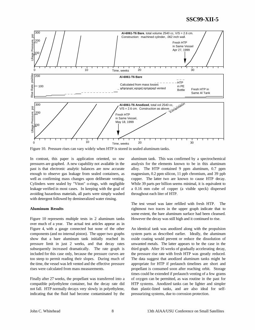
Figure 10. Pressure rises can vary widely when HTP is stored in sealed aluminum tanks.
In contrast, this paper is application oriented, so rawpressures are graphed. A new capability not available in thepast is that electronic analytic balances are now accurateenough to observe gas leakage from sealed containers, aswell as confirming mass changes upon deliberate venting.Cylinders were sealed by "Viton" o-rings, with negligibleleakage verified in most cases. In keeping with the goal ofavoiding hazardous materials, all parts were simply washedwith detergent followed by demineralized water rinsing.
Aluminum Results
Figure 10 represents multiple tests in 2 aluminum tanksover much of a year. The actual test articles appear as inFigure 4, with a gauge connected but none of the othercomponents (and no internal piston). The upper two graphsshow that a bare aluminum tank initially reached itspressure limit in just 2 weeks, and that decay ratessubsequently increased dramatically. The rate graph isincluded for this case only, because the pressure curves aretoo steep to permit reading their slopes. During much ofthe time, the vessel was left vented and the effective pressurerises were calculated from mass measurements.
Finally after 27 weeks, the propellant was transferred into acompatible polyethylene container, but the decay rate didnot fall. HTP normally decays very slowly in polyethylene,indicating that the fluid had become contaminated by the
aluminum tank. This was confirmed by a spectrochemicalanalysis for the elements known to be in this aluminumalloy. The HTP contained 9 ppm aluminum, 0.7 ppmmagnesium, 0.2 ppm silicon, 11 ppb chromium, and 39 ppbcopper. The latter two are known to cause HTP decay.While 39 parts per billion seems minimal, it is equivalent toa 0.16 mm cube of copper (a visible speck) dispersedthroughout each liter of HTP.
The test vessel was later refilled with fresh HTP. Therightmost two traces in the upper graph indicate that tosome extent, the bare aluminum surface had been cleansed.However the decay was still high and it continued to rise.
An identical tank was anodized along with the propulsionsystem parts as described earlier. Ideally, the aluminumoxide coating would prevent or reduce the dissolution ofunwanted metals. The latter appears to be the case in thethird graph. After 16 weeks of gradually accelerating decay,the pressure rise rate with fresh HTP was greatly reduced.The data suggest that anodized aluminum tanks might beappropriate for HTP if prelaunch timelines are short andpropellant is consumed soon after reaching orbit. Storagetimes could be extended if prelaunch venting of a few gramsof oxygen can be permitted, as was routine in the past forHTP systems. Anodized tanks can be lighter and simplerthan plastic-lined tanks, and are also ideal for self-pressurizing systems, due to corrosion protection.

SSC99-XII-5
John C. Whitehead 9 13th AIAA/USU Conference on Small Satellites
Ulla
ge P
ress
ure,
psi
300
200
100
Time, weeks0 10 20 30
Ulla
ge P
ress
ure,
psi
300
200
100
Time, weeks0 10 20 30
Polycarbonate , 165 cc total volume, V/S = 1.4 cm.Construction: cylinder machined from bar.
Polyvinylidene Fluoride (PVDF) , 305 cc total volume.Construction: thin aluminum tube having .025 in thick PVDF liner.
Fresh HTPin Same Vessel,April 29, 1999
Extrapolation
Started April 29, 1999 with fresh distilled 85% HTP.(vessel contained stabilized HTP for previous 22 months)
Leakage
Leakage
LeakLeak
Figure 11. Some polymers offer the potential for many months of sealed HTP storage.
Plastic Results
The effects of exposing HTP to two different plastic tankwalls are displayed in Figure 11. Note that these vessels aremuch smaller than those in Figure 10, with roughly half thevolume/surface ratios. If the reaction occurs on the surfaceonly, pressure rises shown in Figure 11 would be half asfast if scaled up to the larger size.
On the polycarbonate graph, the lower curves are actualpressure readings while the upper curves include theadditional rise which would have occurred without externallosses. While this is labeled as leakage, contributions fromoxygen permeation have not been ruled out.
The best results were obtained with polyvinylidene fluoride(PVDF). Its molecular structure is effectively a hybridbetween "Teflon" (PTFE) and polyethylene, both of whichhave similarly excellent HTP compatibility. However,PVDF is more rigid and easier to fabricate parts out of thanthese related materials. An ongoing activity is to fabricatelarger aluminum tanks lined with PVDF. Based onmeasurements to date, one-year unvented storage should bepossible for tanks designed to have similar pressure limitsand ullage volumes.
Perspective on Storage
It must be emphasized that a complete treatment of the long-term stability of hydrogen peroxide is beyond scope here.For example, decay increases with temperature, so flighttanks should be tested under representative conditions overappropriate times. Decay and materials compatibility havebeen discussed extensively in the literature, e.g. by Schumb
et al.6 These authors noted that the ideal situation for longterm storage is pure HTP in a clean container having nocatalytic activity. Unstabilized HTP is also the best for longthruster life.
Some remarks made in Reference 1 unfortunately ignoredrising decay rates and the importance of homogeneousdecay due to contaminants in solution. In particular, thepotential value of stabilizers in metal tanks should not beruled out, to the extent that they mitigate the catalytic effectof metals in solution. A previous paper discussedheterogeneous decay on tank walls versus decay in solution,for sealed storage.7
Actual long term storage in sealed containers is the mostrealistic material compatibility test relevant to spacecrafttanks. HTP in vented containers might gain atmosphericwater, which introduces mass errors into decay ratemeasurements. With or without leaks, atmosphericconstituents cannot enter a pressurized container.
Discussion
HTP offers the potential for relatively low cost rapiddevelopment and testing of liquid propulsion customizedfor micro satellites. In terms of performance and spacecraftlifetime, HTP does not compete with hydrazine. Thus it iscomforting that concepts for self-pressurization, advancedwith HTP, can also be applied to hydrazine systems in orderto avoid gas bottles while still offering gas jet attitudecontrol to facilitate miniaturization. Decomposed hydrazineoffers more performance even after cooling, because itsconstituents have lower molecular weights and do notcondense as easily as the water in decomposed HTP.
SSC99-XII-5
John C. Whitehead 10 13th AIAA/USU Conference on Small Satellites
Isp measurements reported herein indicate that thepotentially 2-phase product gas (i.e. with condensing steam)still offers higher Isp than nitrogen when used in miniaturegas jets for attitude control. Temperatures are low enoughto permit using aluminum and fluoroelastomer seals inwarm gas applications. Performance is even higher formonopropellant HTP liquid thrusters that are appropriatefor translational maneuvers. Further, a fuel can be added ifmore challenging maneuvers warrant greater complexity.
When compared with compressed nitrogen, an equal massof liquid HTP occupies 2-5 times less volume. Order-of-magnitude lower pressures also permit lighter tanks, evenwhen the HTP tanks are massive enough to serve asprimary structure while absorbing heat from warmpressurant gas. This is still true for bolt-together designsthat have plastic liners for long term storage. Overall, self-pressurizing HTP propulsion technology appears to befeasible and attractive for tiny satellites, so work towardflight systems continues.
Acknowledgments
LLNL's MicroSat Program team made it possible toshowcase and test the propulsion advances described hereinin the context of autonomously-operating prototypesatellites. Key individuals include Joe Kordas as DeputyProgram Leader and Test Director, Don Antelman, EricBreitfeller, Mark Jones, Larry Ng, Darron Nielsen, JeffRobinson, Bill Taylor, Dean Urone, and Bruce Wilson.
Work was supported by the U.S. Air Force ResearchLaboratory. The authors wish to thank Christine Anderson,David Barnhart, and Steven Rodgers. This work wassponsored by the U.S. Government and performed by theUniversity of California Lawrence Livermore NationalLaboratory under Contract W-7405-Eng-48 with the U.S.Department of Energy.
References
1. Whitehead, J.C., "Hydrogen Peroxide Propulsion for Smaller Satellites," SSC98-VIII-1, The 12th Annual Utah State University Small Satellite Conference, 1998. (or see http://www.ee.surrey.ac.uk/ee/cser/uosat/conf/wpapers.htm)
2. Simpkin, A.J., M.L. Chazen, et al, "KEW Divert Vehicle Propulsion System Technology Verificationand Risk Reduction Program Phases I-V," vol 1, TR-PL-12360, Atlantic Research Corporation. Also Air Force Astronautics Laboratory report nr AFAL-TR-88-020, November 1988.
3. Whitehead, J.C., "Mars to Orbit with Pumped Hydrazine," American Institute of Aeronautics and Astronautics paper nr 99-2150, 1999.
4. Ledebuhr, A.G., J.F. Kordas, et al, "Autonomous,Agile, Micro-Satellite Technology for Use in Low Earth Orbit Missions," SSC98-V-1, The 12th Annual Utah State University Small Satellite Conference, 1998.
5. Burtoft, A.C., "A Small Combustion Chamber for SpaceApplication," Journal of the British InterplanetarySociety, 20, pp. 48-52, April 1965.
6. Schumb, W.C., C.N. Satterfield, & R.L. Wentworth, "Hydrogen Peroxide," Reinhold Publishing, New York, 1955 (reprinted by University Microfilms).
7. Monger, James M., "Sealed Storage of Concentrated Hydrogen Peroxide," Chemical Propulsion Information Agency, Publication No. 72, paper no. 69-1130I, 1965.
Appendix: Tank Temperature Predictions
Pure hydrogen peroxide releases 2889 J/g upondecomposing, or 2456 J/g for 85% HTP. The latterproduces 60% water by mass and 40% oxygen. Waterrequires 2252 J/g to vaporize at 212 F (100 C), fallingslightly to 1915 J/g at 400 F (205 C). Notably, about halfthe reaction energy of 85% HTP is associated with thewater phase change.
When decomposed HTP is used for tank pressurization, aquantity of gas proportional to tank volume introduces aproportionate amount of heat into the tank over the courseof expulsion. A worst-case tank temperature would result ifall the excess energy is absorbed by the tank wall with nolosses. This energy balance can be determined from thespecific heat and mass of the tank wall.
For example, if decomposed 85% HTP at 300 psi cools to300 F, approximately 90% of its steam has condensed. Thebulk density is near 40 g/l for this two-phase mixture.Multiplying by 2000 J/g indicates that about 80 kJ must beabsorbed by the tank walls for each liter of volume.
At 0.9 J/g-C, aluminum accepts 115 J/g upon heating by128 C, i.e. from 21 C (70 F) to 149 C (300 F). Thus in theworst case of no heat losses, about 700 grams of tank wallis needed per liter of volume. Note that a tank half as heavyat 350 g/l would equilibrate around 400 F, largely becausereduced steam condensation yields a reduction in pressurantmass.

SSC99-XII-5
John C. Whitehead 11 13th AIAA/USU Conference on Small Satellites
The above calculations indicate ideal limits, not tank designcriteria. In particular, the liquid propellant in the tank alsoabsorbs heat. The specific heat of 85% HTP is 2.85 J/g-C,or 365 J/g over the 128 C rise considered above. Thus only220 g of HTP per liter of ullage is enough to accept all theexcess pressurant heat at 300 psi and 300 F. In reality,external losses are also significant for operational lifetimes(total time for tank expulsion) exceeding just a few minutes.
High ullage temperatures without steam condensationwould theoretically improve system performance. However,the pressurant is a small fraction of system propellant forthe HTP systems tested. Therefore, it is a practicalcompromise to let steam condense in the tank whileavoiding excessive temperatures there.
Biography
John Whitehead earned undergraduate degrees in bothscience and engineering from Caltech. He received adoctorate in mechanical dynamics and controls from theUniversity of California, Davis, in 1987. At the LawrenceLivermore National Laboratory, he led the development ofminiature pump-fed rocket engines. Among hispublications are those which have contributed towardunderstanding unsolved propulsion problems, such asSSTO and Mars departure. Since 1996, he has leddevelopment of small-scale hydrogen peroxide propulsionsystems.
Mike Dittman earned his undergraduate degree inmechanical engineering from California Polytechnic StateUniversity, San Luis Obispo. He received his masters inmechanical engineering, controls and dynamics, from SanJose State University in 1993. Beginning in 1987 at SpaceSystems/Loral he was a lead engineer for many satelliteoperations including assembly, alignments, integration &test, control mechanism design & development, andspacecraft systems. Since 1997 he has made a broad set ofcontributions to micro satellite technology developmentefforts at LLNL.
Arno Ledebuhr completed studies in physics and math in1976 at the University of Wisconsin, then earned mastersand doctorate degrees in physics from Michigan State in1982. He spent the following 4 years at Hughes, where hereceived 13 patents in projection display technology. AtLLNL since 1986, he led advanced sensor development forthe Brilliant Pebbles interceptor program, and the design ofthe 1994 Clementine lunar imaging payload. In 1996 hewas the Clementine II program leader and is currently theMicroSat Technologies program leader.