July 1993 DOC: IEEE P802.11-93/95 IEEE 802.11 Wireless ... · Wireless Access Method and Physical...
28
July 1993 DOC: IEEE P802.11-93/95 IEEE 802.11 Wireless Access Method and Physical Specification Distributed Access WMAC Synchronization and Power Management Mechanisms Wim Diepstraten NCR WCND-Utrecht NCR/AT&T Network Product Group Nieuwegein The Netherlands Tel: (31)-3402-76482 Fax: (31)-3402-39125 Email: [email protected] Abstract Greg Ennis Symbol Technologies 1101 S. Winchester Blvd., Suite B-110 San Jose, CA USA 95128 Tel: (408) 249-9890 Fax: (408) 446-4630 Email: [email protected] This document provides some further details regarding a proposed Medium Access Control protocol for a wireless local area network (the Wireless MAC, or WMAC). This protocol is based on a distributed access mechanism called Carrier Sense Multiple Access with Collision Avoidance (CSMA/CA). Certain aspects of the proposed WMAC have already been presented to the IEEE 802.11 committee, as documented in 802.11-92/51 and 802.11-93nO. The earlier submissions to 802.11 focused on the fundamental CSMA/CA protocol and the manner in which time-bounded services can be supported with this distributed access method. This document expands upon these concepts by presenting details of the basic synchronization and power management mechanisms. Both infrastructure and ad hoc configurations are covered. Submission 1 G. Ennis and W. Diepstraten
Transcript of July 1993 DOC: IEEE P802.11-93/95 IEEE 802.11 Wireless ... · Wireless Access Method and Physical...

July 1993 DOC: IEEE P802.11-93/95
IEEE 802.11 Wireless Access Method and Physical Specification
Distributed Access WMAC Synchronization and Power Management Mechanisms
Wim Diepstraten NCR WCND-Utrecht NCR/AT&T Network Product Group Nieuwegein The Netherlands Tel: (31)-3402-76482 Fax: (31)-3402-39125 Email: [email protected]
Abstract
Greg Ennis Symbol Technologies 1101 S. Winchester Blvd., Suite B-110 San Jose, CA USA 95128 Tel: (408) 249-9890 Fax: (408) 446-4630 Email: [email protected]
This document provides some further details regarding a proposed Medium Access Control protocol for a wireless local area network (the Wireless MAC, or WMAC). This protocol is based on a distributed access mechanism called Carrier Sense Multiple Access with Collision Avoidance (CSMA/CA).
Certain aspects of the proposed WMAC have already been presented to the IEEE 802.11 committee, as documented in 802.11-92/51 and 802.11-93nO. The earlier submissions to 802.11 focused on the fundamental CSMA/CA protocol and the manner in which time-bounded services can be supported with this distributed access method. This document expands upon these concepts by presenting details of the basic synchronization and power management mechanisms. Both infrastructure and ad hoc configurations are covered.
Submission 1 G. Ennis and W. Diepstraten
July 1993 DOC: IEEE P802.11·93/95
1. Introduction
1.1 Purpose and Scope of this Document
This proposed WMAC protocol is part of a larger protocol architecture, which when implemented within actual equipment will provide a complete wireless LAN system. Two types of wireless LANs are intended to be supported by the equipment which implements these protocols:
• Ad Hoc Wireless LAN, which is a (typically small) network of stations all within range of each other station's wireless transceivers.
• Infrastructure Wireless LAN, which includes special nodes called access points which are interconnected via a (typically wired) distribution system to provide a network for wireless stations encompassing a greater area than would be possible in the ad hoc case, and which provides access to existing wired networks.
The stations within a wireless LAN may be mobile. In the case of an infrastructure LAN with multiple access points, the protocol provides for the movement of stations from the area supported by one access point to that supported by another.
Another provision of the WMAC protocol described here is support for power conservation within the stations. Since mobile stations are likely operating on lightweight batteries, power conservation is a critical feature for these stations.
Both asynchronous data service and isochronous (time bounded) services are supported. All stations and access points would support the asynchronous service described in this document. The isochronous service is viewed as an optional service, and would be supported only in certain infrastructure configurations.
Earlier submissions to IEEE 802.11 covered the fundamental CSMA/CA protocol and the manner in which time-bounded services can be supported with this distributed access method. This document expands upon these concepts by presenting details of the basic synchronization and power management mechanisms. Both infrastructure and ad hoc configurations are covered.
Section 2 first presents an overview of the basic concepts. Section 3 then goes into the details of a synchronization mechanism in which all nodes within a Basic Service Set are coordinated with a common clock. This synchronization can be used for a variety of purposes within the wireless LAN, including the support of time bounded services, management of certain PHYs (e.g. FHSS), and mobility support. In this document, we focus on the use of synchronization to provide a flexible power management function for
Submission 2 G. Ennis and W. Diepstraten

July 1993 DOC: IEEE P802.11·93/95
stations. The power management scheme is presented in Section 4 for infrastructure networks and in Section 5 for ad hoc configurations.
1.2 Acknowledgments
The following individuals have also contributed to the development of the concepts in this document: LaRoy Tymes, Sarosh Vesuna and Chris Zegelin (Symbol), and Jan Kruys, Henri Moelard and Henk van Bokhorst (NCR).
1.3 References
[1] IEEE P802.11-92/51 A Wireless MAC Protocol Comparison, Wim Diepstraten, NCR
[2] IEEE P802.11-93/70 A Distributed Access Protocol Supporting Time-Bounded Services, Wim Diepstraten, NCR
[3] IEEE P802.11-93/40 The Wireless Hybrid Asynchronous Time-Bounded MAC Protocol, Phil Belanger and Ken Biba, Xircom
Submission 3 G. Ennis and W. Diepstraten
July 1993 DOC: IEEE P802.11-93/95
2. General Overview
The basic features of the proposed WMAC were described in [2]. The reader is referred to that document for a description of the basic CSMNCA access procedure, MAC-level acknowledgments, and the support of time-bounded services.
2.1 Basic and Extended Service Area ~
The basic building block of a wireless network is a cell called a BSA (Basic Service Area). A group of stations within a BSA that are associated with each other to communicate, forms a BSS or Basic Service Set. The size of a cell is dependent on the environment and the characteristics of the wireless transceivers. Larger areas can be covered by using multiple BSAs, which can be interconnected using Access Points (APs) and a Distribution System. This is called an ESA or Extended Service Area. The set of stations within multiple BSSs which are connected via a Distribution System is an Extended Service Set (ESS). Each ESS is distinguished by a Network ID (NID), while within one ESS, each BSS is distinguished by an Access Point ID CAPID) code.
2.2 Infrastructure Network
To interconnect different BSS's to form a larger coverage ESS, an infrastructure is needed, which consists of specialized stations called Access Points CAP) and a Distribution System to interconnect the Access Points.
2.2.1 Access Points
An Access Point is part of the infrastructure and provides the following basic functionality:
• Authentication, Association and Reassociation services that allow stations to remain connected to the infrastructure while moving from one BSA into another.
• Power Management functions that allow stations to operate in a Power Save mode. This includes a temporary frame buffering function, and associated traffic announcement functionality to allow station transceivers to be powered down most of the time.
• Synchronization functions which ensure that all stations currently associated with the AP are synchronized on a common clock. This synchronization is used, for example, in supporting time bounded services and power management.
Submission 4 G. Ennis and W. Diepstraten
~--.
. -----.-~--

July 1993 DOC: IEEE P802.11·93/95
2.2.2. Distribution System
To interconnect different BSS's via AP's, a Distribution System is needed. It also provides intemetworking facilities to interface to an existing network. The Distribution System can be built from wired network components, or it could be (partly) wireless. The minimum Infrastructure configuration consists of a single Access Point that is not connected to other AP's or to a standard wired LAN by a distribution system. Stations within one BSS are associated with a specific Access Point.
2.3 Ad· Hoc Network
A special case is a single ESA that does not have an Infrastructure. This is called an AdHoc Network, which can be fonned by a number of stations (such as in a meeting room, for instance). This network should be able to be set up fast, and would perhaps only last for the duration of the meeting, without the need for any infrastructure provisions.
It would further allow communication between stations without the need to be registered to an available infrastructure, and is independent of any installed infrastructure.
The following figures depicts the two types of networks.
--
--
Submission
~---- -Separate NID
------Ad· Hoc Network
5
-
-/
/ ,/
G. Ennis and W. Diepstraten

July 1993
,/
/
I
\~ " BSS-A
""" -
Distribution System
\ \ J BSS-B
~ //IS ......... -
Infrastructure Network
2.4 Basic WMAC Protocol Approach
DOC: IEEE P802.11-93/95
The most important requirement for a Wireless MAC protocol is its robustness against all kind of interference. It is also important to use a protocol that is able to share the medium in an efficient way. The medium must be shared with other interoperable devices, but also with dissimilar devices operating in the same band.
This is achieved by using a CSMNCA + Ack Protocol. This stands for Carrier Sense Multiple Access with Collision Avoidance and MAC level Acknowledgment. The CSMA/CA part is designed to share the medium in a spectral efficient way. The MAC level Acknowledgment allows the detection of a lost frame and its recovery by retransmission at the MAC level.
All Asynchronous frame transmissions will use the CSMA/CA+Ack approach, except for BroadcastlMulticast frames directed to stations, which are not acknowledged. The Time Bounded Service is built on top of the CSMA/CA protocol, with a fixed high priority compared to the Asynchronous Services. In addition the Acknowledgment mechanism implementation is somewhat different for the Time Bounded Service.
The details of the proposed CSMNCA mechanism can be found in [2].
2.5 Power Management
An essential part of the WMAC is the ability to conserve mobile station power consumption as much as possible. In Infrastructure mode this is achieved by the following principle steps:
• Synchronize all stations operating in Power Save Mode within one BSS.
Submission 6 G. Ennis and W. Diepstraten -

July 1993 DOC: IEEE P802.11·93/95
• Allow stations to power down their transceivers for most of the time. • Temporarily buffer incoming frames for sleeping stations in an Access Point. • Announce the buffered frames to the stations at regular predetermined intervals, so
that a station can sleep until it wishes to hear such an announcment, at which point it can take steps to ensure that any buffered frames are properly received.
Different Power Management modes are provided to trade-off station power consumption and performance.
In Ad-Hoc Networks a similar approach is followed that makes use of the fact that all stations are synchronized with each other. No central buffering function is available in this configuration, so a frame may be buffered within a station until all transceivers are awake.
2.6 Station Mobility
Stations will normally "Associate" with an Access Point as part of their initialization process. They will determine the "best quality" link by listening to frames which are transmitted by each Access Point at regular intervals. These can be thought of as "beacons." The signal level and quality of the beacons from each of the AP's that are received during a certain scan time interval can be evaluated by the stations.
Stations can then Associate with the new Access Point. The Access Point will in turn follow a hand-off protocol across the distribution system, to inform the other Access Points regarding the new association.
The beacon signaling function can be accomplished using the TIM frames (described below) which are periodically generated to synchronize all stations within a BSS, and which also have a power management function.
Submission 7 G. Ennis and W. Diepstraten

July 1993 DOC: IEEE P802.11-93/95
3. Synchronization
It is beneficial for a variety of reasons to synchronize all nodes within a single BSS to a common clock. As we will describe in this section, synchronization does not require a traditional synchronous protocol in which the time domain is partitioned into fixed frames, in which certain transmissions are mandated to occur at designated moments. Such an approach would be incompatible with a CSMA access method. Instead, the method used here to achieve synchronization is completely compatible with the basic CSMA/CA p~ocol in which stations defer upon perceiving a busy medium. Similarly, the applications of synchronization are compatible with CSMNCA.
3.1 Basic Approach and Applications
In the basic approach, a designated node plays the role of a timing coordinator. In the case of an infrastructure BSS, the Access Point will assume this responsibility, whereas in the case of an ad hoc BSS it may be an ordinary station which is selected for this purpose.
The timing coordinator maintains an internal timer which will be used to synchronize the other BSS participants. The timing coordinator will periodically transmit a timestamp value derived from its internal timer. This timestamp may be part of a frame which includes other information. For example, in the case of an infrastructure network, the timestamp will be included with every transmission of a TIM, or Traffic Indication Message, which is periodically generated by the AP in order to inform power conserving stations that traffic has been buffered in the AP. In the case of ad hoc networks, the corresponding frame is called the PSync, which similarly includes the timestamp.
The timing coordinator may experience a busy medium before transmitting the timestamp. To ensure that the timestamp value adequately represents the internal timer, the timestamp field is not filled in until the actual transmission occurs, i.e. after the deferraL Thus the synchronizing transmissions are generated in a fashion completely compatible with the basic CSMA/CA access method.
Each station maintains a timer similar to the internal timer of the timing coordinator. A timestamp is always transmitted within a frame which is addressed so as to only be received by stations within a given BSS (and hence in direct wireless contact). Consequently the delay between transmission and reception is essentially identical (and small) for all stations. The receiving stations can thus synchronize their own internal timers based upon the reception of the timestamp. It is not necessary that a station properly receive each timestamp, provided that the timestamps are generated sufficiently frequently.
With all stations within the BSS synchronized, specific events can be scheduled to occur at specific times. This may involve the transmission of a particular type of frame by a certain
Submission 8 G. Ennis and W. Diepstraten
--
July 1993 DOC: IEEE P802.11·93/95
station (the timing of which can then be anticipated by the other stations), or the transition of the entire BSS into a new state. The following are example applications which can be accommodated within a synchronized BSS:
• Power management, allowing nodes to power off their receiver during certain periods if they know that no frames will be sent to them
• PRY management, such as the determination of hop intervals in an FHSS PRY
• Isochronous traffic support, as described in [2].
It is important to point out that even when the synchronization is used to schedule the transmission of a specific frame, it is not necessary that the frame be transmitted at that exact moment. Instead, the frame's transmission can be deferred as usual according to the basic CSMA/CA algorithm, and the scheduled time should be viewed as a "no earlier than" time. This is the method used to ensure that regular timestamps are transmitted compatibly with CSMNCA, and the same method can be used for all scheduled transmissions. Using the terminology ofTDMA approaches (in which the term "frame" is used for the periodic divisions of the time domain), we can describe our use of synchronization as creating virtual frames in the time domain which define the moments at which transmissions are scheduled to occur, even though they may in fact occur later due to CSMA deferrals.
Later sections of this document will focus on power management and the manner in which use can be made of synchronization. But frrst we describe how the basic synchronization itself can be achieved and maintained even with stations which are operating in a powersave mode, i.e. stations which power down their receiver for extended periods of time.
3.2 Acquisition and Maintenance of Synchronization
Given that a timing coordinator is generating periodic timestamps as described in the previous section, stations must receive these timestamps and update their internal timers. There are two cases:
• Stations that are not concerned with conserving power, and hence leave their receiver on continuously.
• Stations which conserve power by powering off their receiver.
The first case is a simplification of the second, and consequently we describe here the manner in which a power-conserving station maintains synchronization. It is assumed that a station which wishes to conserve power can power off its receiver while maintaining its own internal timer.
Submission 9 G. Ennis and W. Diepstraten
July 1993 DOC: IEEE P802.11-93/95
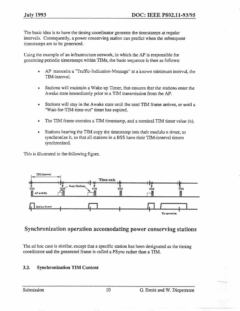
The basic idea is to have the timing coordinator generate the timestamps at regular intervals. Consequently, a power conserving station can predict when the subsequent timestamps are to be generated.
U sing the example of an infrastructure network, in which the AP is responsible for generating periodic timestamps within TIMs, the basic sequence is then as follows:
• AP transmits a "Traffic-Indication-Message" at a known minimum interval, the TIM-interval.
• Stations will maintain a Wake-up Timer, that ensures that the stations enter the Awake state immediately prior to a TIM transmission from the AP.
• Stations will stay in the Awake state until the next TIM frame arrives, or until a "Wait-for-TIM-time-out" timer has expired.
• The TIM frame contains a TIM timestamp, and a nominal TIM timer value (n).
• Stations hearing the TIM copy the timestamp into their modulo n timer, to synchronize it, so that all stations in a BSS have their TIM-interval timers synchronized.
This is illustrated in the following figure.
~ I I Time-axis .... ~ Busy M tdlu", I f It ;;;" ~ TIM TIM
Om 01 R TIM
01 '11M
I APactlvlty
lj'l Station Power ,
Tx operation
Synchronization operation accomodating power conserving stations
The ad hoc case is similar, except that a specific station has been designated as the timing coordinator and the generated frame is called a PSync rather than a TIM.
3.3. Synchronization TIM Content
Submission 10 G. Ennis and W. Diepstraten -
__ - .. _0_-

July 1993 DOC: IEEE P802.11·93/95
The timestamp value in the TIM frame is the value of the free-running TllvCInterval timer in the AP, which is copied in the frame at the moment that actual medium access is achieved. The start of the MAC frame is used as a timing reference. This allows all stations associated with this AP to achieve accurate synchronization.
Stations receiving the TIM, can accurately update their local timer by using the difference between the local timer and the timestamp information at the moment of TIM arrival, to
<t< update the local timer.
This accurate synchronization capability will allow stations to go into the Doze state, until just before a TIM is expected to arrive. Stations would need to make sure that they power-up their receiver a certain time before the TIM is expected, to ensure that the receiver is fully capable of receiving the expected TIM. The time synchronization accuracy will greatly reduce the on-time needed to check whether traffic is pending for that station.
4. Power Management in an Infrastructure Network
A wireless station will consume power through both transmission and reception. Since transmitters are powered on only when an actual transmission is occurring, no further reduction in power consumption is possible for transmission. However, receivers are typically powered on even when no actual reception is occurring, to ensure that if a frame does appear it will be properly handled. This presents an opportunity for power savings if the receiver can be powered off except when actually needed.
The mechanism described in this section allows stations to operate with receivers powered off for much of the time while still ensuring that frames will be received. In general there is an inverse relationship between the power consumed and the performance achieved, and it will be seen that this scheme allows stations to operate at various points on the "power/performance" tradeoff curve, independent of other stations. Also, the scheme does not rely upon higher-level software making the receiver on/off decision, and hence is application -independent.
4.1 Overview
The basic approach is for stations to inform the AP if they wish to enter a powerconserving mode. In this case, the AP will not arbitrarily transmit frames to the station, but will buffer frames and will only transmit them at designated times.
The stations which currently have buffered frames within the AP are identified in a Traffic Indicator Message, or TIM, which is periodically generated by the AP. A station may determine that a frame is buffered for it by listening to a TIM, and can then take action to
Submission 11 G. Ennis and W. Diepstraten
July 1993 DOC: IEEE P802.11·93/95
ensure that the frame is received. The TIM also includes a timestamp which is used for synchronization, as described in Section 3 above.
TlMs are periodically generated by the AP, separated by a time interval called the TIM_Interval (which is a BSS parameter known by all stations within the BSS upon association with the AP). Stations can individually determine how frequently to listen for TIMs, given by a per-station Listen _Interval parameter, the value of which may depend upon the station's desired power/performance target. Since TIMs are generated at regular inthvals (subject to CSMA deferral as described in Section 3), stations may synchronize their Listen_Interval with the TIM_Interval so as to ensure that the TIM is likely to arrive immediately after the receiver is powered on.
To accommodate the wide range of anticipated station requirements as regards the tradeoff of power consumption versus performance, the protocol allows for two ways in which a station may obtain its buffered frames. Stations operating in the Power Save Polling mode (PSP) will transmit a short Poll frame to the AP, which will respond with the corresponding buffered frame. Such stations may choose to listen to each TIM or may choose to listen only to occasional TIMs, depending upon their desired level of power consumption and performance. Other stations may operate in the Power Save Non· Polling mode (PSNP), in which case they listen for certain specific TIMs (called Delivery TIMs, or DTIMs) after which the AP will deliver their buffered frames without waiting for a poll. Broadcast or multicast frames are delivered to all stations following the DTIM transmissions.
It is anticipated that different networks may set the TIM_Interval to different values depending upon the nature of the applications being supported. It is likely that most applications would be well served with TIMs generated every 20 to 50 milliseconds, and with DTIMs every 50 to 200 milliseconds.
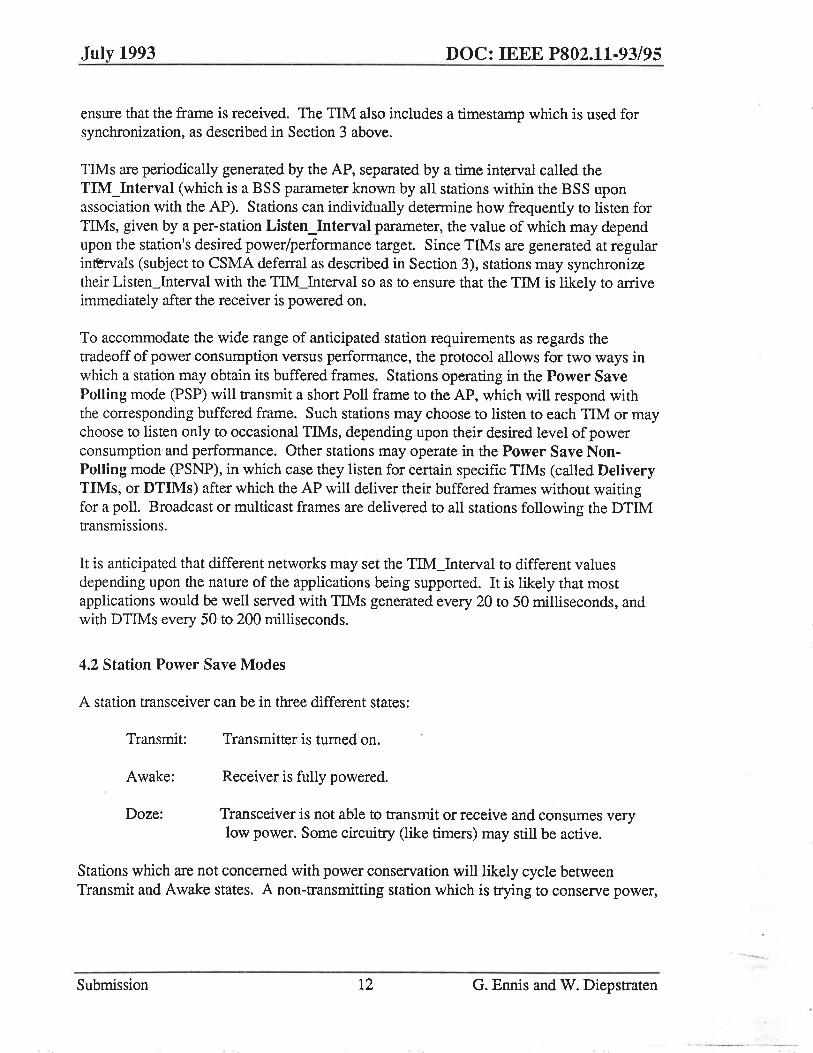
4.2 Station Power Save Modes
A station transceiver can be in three different states:
Transmit:
Awake:
Doze:
Transmitter is turned on.
Receiver is fully powered.
Transceiver is not able to transmit or receive and consumes very low power. Some circuitry (like timers) may still be active.
Stations which are not concerned with power conservation will likely cycle between Transmit and Awake states. A non-transmitting station which is trying to conserve power,
Submission 12 G. Ennis and W. Diepstraten
---
July 1993 DOC: IEEE P802.11-93/95
however, will go to the Awake state only if there is a strong likelihood that a frame is about to be received, and otherwise it will reside in the Doze state.
Given these transceiver states, various power-save modes for a station are defined. The modes differ in the manner that the station cycles through the transceiver states, and in the actions that the station takes in order to receive a frame.
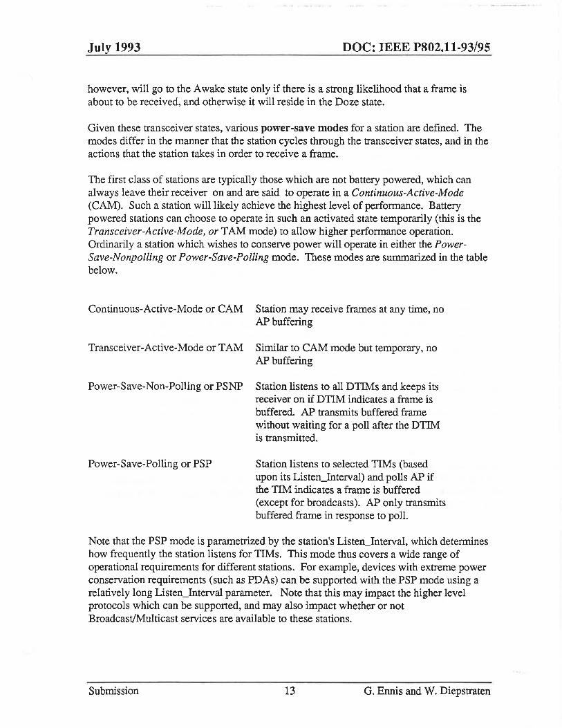
The first class of stations are typically those which are not battery powered, which can always leave their receiver on and are said to operate in a Continuous-Active-Mode (CAM). Such a station will likely achieve the highest level of perfonnance. Battery powered stations can choose to operate in such an activated state temporarily (this is the Transceiver-Active-Mode, or TAM mode) to allow higher performance operation. Ordinarily a station which wishes to conserve power will operate in either the PowerSave-Nonpolling or Power-Save-Polling mode. These modes are summarized in the table below.
Continuous-Active-Mode or CAM Station may receive frames at any time, no AP buffering
Transceiver-Active-Mode or TAM Similar to CAM mode but temporary, no AP buffering
Power-Save-Non-Polling or PSNP Station listens to all DTIMs and keeps its receiver on if DTIM indicates a frame is buffered. AP transmits buffered frame without waiting for a poll after the DTIM is transmitted.
Power-Save-Polling or PSP Station listens to selected TIMs (based upon its Listen_Interval) and polls AP if the TIM indicates a frame is buffered (except for broadcasts). AP only transmits buffered frame in response to polL
Note that the PSP mode is parametrized by the station's Listen_Interval, which determines how frequently the station listens for TIMs. This mode thus covers a wide range of operational requirements for different stations. For example, devices with extreme power conservation requirements (such as PDAs) can be supported with the PSP mode using a relatively long Listen_Interval parameter. Note that this may impact the higher level protocols which can be supported, and may also impact whether or not BroadcastlMulticast services are available to these stations.
Submission 13 G. Ennis and W. Diepstraten
July 1993 DOC: IEEE P802.11-93/95
Stations may transition between modes if desired. Transitions between any of the major modes identified in the table require that the AP be informed. Transitions within the PSP mode (Le. changes to the Listen_Interval) do not require any interaction with the AP. One situation in which mode transition may be appropriate is upon frame transmission, under the assumption that any transmitted frame is likely to be followed by a frame in the reverse direction. For example, a power-save station may transition to TAM mode following such a transmission, or alternatively such a station may operate in PSP mode while listening for all TIMs.
4.3 Access Point TIM Transmissions
Frames containing a TIM (Traffic-Indication-Message) are sent at regular intervals. Apart from the synchronization information described earlier the TIM will also identify the stations for which traffic is pending and buffered in the AP. In addition it contains an indication whether Broadcast/Multicast traffic is pending, and when it is going to be transmitted.
This information is coded in a virtual bitmap, as described in Section 6. To allow efficient coding, every station is assigned a Station ID code (SID) by the AP as part of the association process. The TIM will identify those stations for which frames are buffered by setting bits in the virtual bitmap which correspond to the appropriate SIDs.
The TIM information (synchronization and virtual bitmap) is to be broadcast at regular predictable intervals. It can be transmitted as a separate TIM frame, or it can be part of another frame, as an optional element. Stations waking up from the doze state will then need to examine all the received frames from its associated AP, disregarding the destination address, to monitor for the TIM element field.
Another use of the periodically generated TIM could be to facilitate the reassociation of stations from one AP to another. Stations that are monitoring the medium for a new AP can use the TIM as a beacon signal that indicates the AP's presence, and which includes the APID code and timing synchronization information needed by a station to re-associate with a different AP.
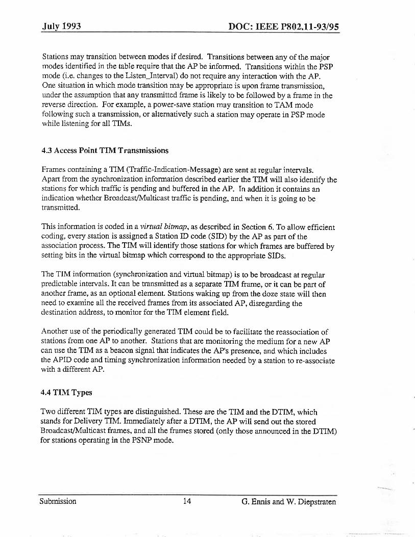
4.4 TIM Types
Two different TIM types are distinguished. These are the TIM and the DTIM, which stands for Delivery TIM. Immediately after a DTIM, the AP will send out the stored BroadcastlMulticast frames, and all the frames stored (only those announced in the DTIM) for stations operating in the PSNP mode.
Submission 14 G. Ennis and W. Diepstraten --
July 1993 DOC: IEEE P802.11-93/95
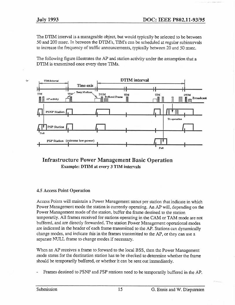
The DTIM: interval is a manageable object, but would typically be selected to be between 50 and 200 msec. In between the DTIM:'s, TIM's can be scheduled at regular subintervals to increase the frequency of traffic announcements, typically between 20 and 50 msec.
The following figure illustrates the AP and station activity under the assumption that a DTIM is transmitted once every three TIMs.
II 0 TIM-Interval ~ , Time-axis II" II DTIM interval
II
m ~ APactlvlty
TIM"'" Busy Medium
61 'oimrmd Frame 1 TIM
DI ~ IYfIM 'I m E3 n roadcast
TIM
Tx operaUon
psp Station (extreme low power)
Poll
Infrastructure Power Management Basic Operation Example: DTIM at every 3 TIM intervals
4.5 Access Point Operation
Access Points will maintain a Power Management status per station that indicate in which Power Management mode the station is currently operating. An AP will, depending on the Power Management mode of the station, buffer the frame destined to the station temporarily. All frames received for stations operating in the CAM or TAM mode are not buffered, and are directly forwarded. The station Power Management operational modes are indicated in the header of each frame transmitted to the AP_ Stations can dynamically change modes, and indicate this in the frames transmitted to the AP, or they can use a separate NULL frame to change modes if necessary.
When an AP receives a frame to forward to the local BSS, then the Power Management mode status for the destination station has to be checked to determine whether the frame should be temporarily buffered, or whether it can be sent out immediately.
Frames destined to PSNP and PSP stations need to be temporarily buffered in the AP.
Submission 15 G. Ennis and W. Diepstraten
July 1993 DOC: IEEE P802.11-93/95
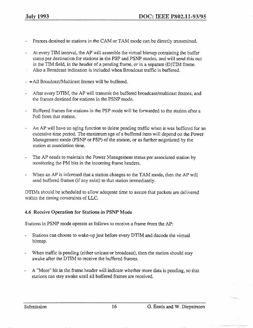
Frames destined to stations in the CAM or TAM mode can be directly transmitted.
At every TIM interval, the AP will assemble the virtual bitmap containing the buffer status per destination for stations in the PSP and PSNP modes, and will send this out in the TIM field, in the header of a pending frame, or in a separate (D)TIM frame. Also a Broadcast indication is included when Broadcast traffic is buffered.
- ~ All BroadcastlMulticast frames will be buffered.
After every DTIM, the AP will transmit the buffered broadcast/multicast frames, and the frames destined for stations in the PSNP mode.
Buffered frames for stations in the PSP mode will be forwarded to the station after a Poll from that station.
An AP will have an aging function to delete pending traffic when it was buffered for an excessive time period. The maximum age of a buffered item will depend on the Power Management mode (PSNP or PSP) of the station, or as further negotiated by the station at association time.
The AP needs to maintain the Power Management status per associated station by monitoring the PM bits in the incoming frame headers.
When an AP is informed that a station changes to the TAM mode, then the AP will send buffered frames (if any exist) to that station immediately.
DTIMs should be scheduled to allow adequate time to assure that packets are delivered within the timing constraints of LLC.
4.6 Receive Operation for Stations in PSNP Mode
Stations in PSNP mode operate as follows to receive a frame from the AP:
Stations can choose to wake-up just before every DTIM and decode the virtual bitmap.
When traffic is pending (either unicast or broadcast), then the station should stay awake after the DTIM to receive the buffered frames.
A "More" bit in the frame header will indicate whether more data is pending, so that stations can stay awake until all buffered frames are received.
Submission 16 G. Ennis and W. Diepstraten

July 1993 DOC: IEEE P802.11-93/95
When no traffic is pending stations can go into the Doze state again, scheduled to wake-up at the next DTIM.
4.7 Receive Operation for Stations in PSP Mode
Stations in PSP mode operate as follows to receive a frame from the AP:
Stations can choose to wake-up just before any TIM. Since these stations need not hear every TIM, they can be in the Doze state for a period longer than the TIM interval. The frequency with which a PSP station listens for TIMs is a dynamic perstation parameter that depends on the power conservation and performance needs of the station, and could range, for example, from once every 20 ms (if TIMs are that frequent) to many seconds.
When traffic is pending (no broadcast), then the station should issue a Poll to retrieve the buffered frame.
A "More" bit in the received frame will indicate whether more traffic for that station was buffered, so the station can Poll until no more frames are buffered for that station.
To receive broadcast frames, the station should wake up at least before every DTIM.
4.8 PSNP and PSP Station Transmitter Operation
When a station wants to transmit, it will wake-up from a possible Doze state, with sufficient time before the actual transmission is started, to ensure stable operation.
A transmitting station will use the CSMA/CA access procedure, and transmit its frame(s).
4.9 Stations operating in the TAM Mode
An AP will send down all the possibly buffered frames immediately after the station has indicated a mode change to the TAM mode to the AP.
An AP will send incoming frames for stations in the TAM mode without any buffering delay.
A bit in the frame header will indicate whether the station wants to change its mode to TAM, to change the AP buffering mode.
A station shall switch to the TAM mode under control of a "Transmit_Holdover" parameter, which indicates how long a station stays awake after every transmission.
Submission 17 O. Ennis and W. Diepstraten

July 1993 DOC: IEEE P802.11-93/9S
When this value is non zero, then the station will change to the TAM mode, and remains in this mode under control of a "TransmiCHoldover" Timer.
When this timer expires, then the station can, for instance, send a NULL frame indicating the mode change back to its original mode to the AP, and goes into the Doze state.
4.10 Stations Operating in the CAM Mode
Stations operating in this mode have their transceivers activated continuously, so they do not need to interpret the traffic announcement part of the TIM frames. Some stations want to synchronize to the TIM Timer, for instance to allow support of Time Bounded Services. All stations will use the TIM frames for re-association monitoring purposes.
S. Power Management in an Ad Hoc Network
In this section we show how the basic power management concepts for infrastructure networks described in Section 4 could be adapted to provide a similar service in the ad hoc case.
5.1 Basic Approach
The basic approach is similar to the infrastructure case in that the stations are synchronized, and frames which are to be transmitted to a power conserving station are first announced (in a quick transmission) by the transmitter. A power conserving station need only listen for these announcements (called PTIMs) to determine if its receiver must be left on.
The difference between the ad hoc and infrastructure case rests in the fact that there is no Access Point which is continuously powered and which can serve as a buffering and forwarding agent for the power conserving stations. Consequently each station must be responsible for generating its own announcements (Le. the PTIMs). These essentially take the form of the header of the actual frame to be transmitted, including the source and destination addresses.
One of the stations, however, needs to take the responsibility of coordinating the time synchronization with other stations within the Ad-Hoc network. The approach is similar to that in the Infrastructure operation mode. However, now the traffic announcement function and the time synchronization function are separated. The time synchronization function is provided by PSync frames, which are issued by one of the stations. The only
Submission 18 G. Ennis and W. Diepstraten
.. ---..... .•.
July 1993 DOC: IEEE P802.11·93/95
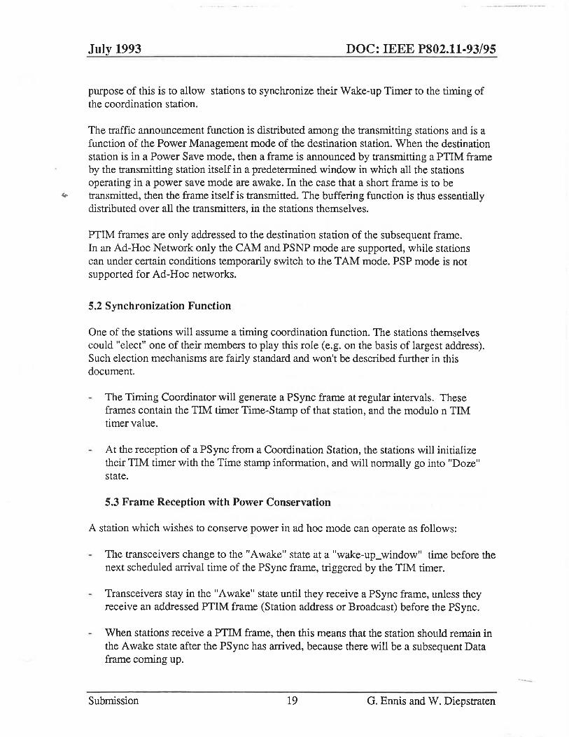
purpose of this is to allow stations to synchronize their Wake-up Timer to the timing of the coordination station.
The traffic announcement function is distributed among the transmitting stations and is a function of the Power Management mode of the destination station. When the destination station is in a Power Save mode, then a frame is announced by transmitting a PTIM frame by the transmitting station itself in a predetennined window in which all the stations operating in a power save mode are awake. In the case that a short frame is to be
.... transmitted, then the frame itself is transmitted. The buffering function is thus essentially distributed over all the transmitters, in the stations themselves.
PTIM frames are only addressed to the destination station of the subsequent frame. In an Ad-Hoc Network only the CAM and PSNP mode are supported, while stations can under certain conditions temporarily switch to the TAM mode. PSP mode is not supported for Ad-Hoc networks.
5.2 Synchronization Function
One of the stations will assume a timing coordination function. The stations themselves could "elect" one of their members to play this role (e.g. on the basis of largest address). Such election mechanisms are fairly standard and won't be described further in this document.
The Timing Coordinator will generate a PSync frame at regular intervals. These frames contain the TIM timer Time-Stamp of that station, and the modulo n TIM timer value.
At the reception of a PSync from a Coordination Station, the stations will initialize their TIM timer with the Time stamp information, and will normally go into "Doze" state.
5.3 Frame Reception with Power Conservation
A station which wishes to conserve power in ad hoc mode can operate as follows:
The transceivers change to the "Awake" state at a "wake-up_window" time before the next scheduled arrival time of the PSync frame, triggered by the TIM timer.
Transceivers stay in the "Awake" state until they receive a PSync frame, unless they receive an addressed PTIM frame (Station address or Broadcast) before the PSync.
When stations receive a PTIM frame, then this means that the station should remain in the Awake state after the PSync has arrived, because there will be a subsequent Data frame coming up.
Submission 19 G. Ennis and W. Diepstraten
-'-

July 1993
This is illustrated in the following figure.
.1" TIM-Interval ·1 II· It
Busy M.dlu PSyn~
Time Coordinator
Station Power
Station Power
Time-axis
DOC: IEEE P802.11·93/95
pi I'Q Wake-up_Wlndow
I III TAM operation
Short Frame Without PTlm
Ad·Hoc Power Management· Basic operation
5.4 Frame Transmission
Each station monitors the power-management status of the other stations. This is determined by examining the power-management bits within the frames generated by the other stations. This is actually only necessary for those stations with whom a given station needs to exchange frames.
To transmit a frame, the following steps transpire:
When the destination station is operating in the CAM (or TAM) mode, then the station will transmit the frame without any buffering delay.
Stations that have a frame to transmit to a destination station that is not operating in the CAM or TAM mode, will wait until their TIM timer indicates a station awake status, which is some time (awake_Window) before the PSync frame would be expected to arrive.
Then this station will first put the destination station into the TAM mode by sending a short PTIM (Peer Traffic Indication Message) frame to the destination station, which is to be Acked by the destination station.
The actual Data frame will normally not be sent until the PSync frame is received. After the Psync frame has been received, only those stations that did receive (or transmit) a PTIM frame will stay in the Awake state.
Submission 20 G. Ennis and W. Diepstraten
-
July 1993 DOC: IEEE P802.11·93/95
The timing of the start of the first PTIM frame should be randomized (backoff before transmission), to prevent multiple PTIMs from colliding.
The PTIM is only the WMAC header of the Data frame, with the appropriate Type field set to indicate a PTIM.
Stations that have something to transmit to stations that are in the PSNP mode will incur an initial delay for the first packet, but it can then change to the TAM mode for a predetermined TransmiCHoldovecTime. This allows high speed data traffic directly between the two stations, once the initial connection has been established by sending the PTIMframe.
6. PDU Formats
Here we present formats for the Protocol Data Units (PDUs, also called frames) which have been discussed in this document. As the focus in this paper is on the synchronization and power management provisions, the depicted formats cover those fields relevant for these operations. Other frames and frame components may be required to support the full range of services desired in the WMAC.
6.1 Basic and Short Formats
There are two basic formats used for frames:
• A Basic Format used for all frames except those of type ACK • A Short Format used for ACK frames.
The difference between the two formats lies in the elimination of the source address and the use of an 8-bit CRC (rather than a 32 bit CRC) in the short format.
Each frame may optionally include a variable length "Elements" subfield which contains one or more "elements". Elements are defmed to have a common general format consisting of a one-octet Code field, a 1 bit More indicator (identifying whether additional elements are present), a 7-bit Link field, and a variable-length element-specific field. Each element is assigned a unique code. The Link field is the number of additional octets in the element (which may be zero).
Certain frame types may require that specific elements be present.
The fields within the frames are defined as follows:
Submission 21 G. Ennis and W. Diepstraten

July 1993 DOC: IEEE P802.11·93/95
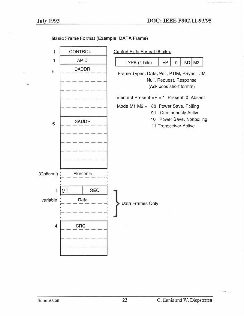
CONTROL: 1 octet control field, including a 4-bit Type field, together with bits indicating whether or not there are elements present in the frame, and bits indicating the power conservation mode in which the station is currently operating.
APID: 8 bit Access Point ID
DADDR: 48 bit Destination Address field
SADDR: 48 bit Source Address field (not present for ACKs)
ELEMENTS: Variable length field containing zero or more elements.
Element format includes 1 octet Code field, 1 bit More indicator, and 7 bit Link field.
Link field indicates the number of remaining octets in the element.
TYPE-DEPENDENT FIELDS: Variable number of fields depending upon frame type. For example, DATA frames include a 1 octet control field containing a More bit and a 4 bit sequence number field, as well as a variable length data field.
CRC: IEEE-standard 32 bit CRC (all frames except ACK), 8-bit CRC (ACK frames)
The following figures depict these two formats.
Submission 22 G. Ennis and W. Diepstraten
'--
July 1993 DOC: IEEE P802.11-93/95
Basic Frame Format (Example: DATA Frame)
1 CONTROL
APID
DADDR r-- - - - - - - -6
I- - - - - - - -
r-- - - - - - - -
r-- - - - - - --
I- - - - - - --
SADDR r-- - - - - - - -6
I-- - - - - - --f- - - - - - --
f- - - - - - --
-- - - - - --
(Optional) : Elements --------, ,
SEQ
variable ' Data --------, ,
, , --------• I
4 CRC f--- ------
f--- --- - --
f-- - ------
Submission
Control Field Format (8 bits):
TYPE (4 bits) I EP I 0 I M1 I M2 I Frame Types: Data, Poll, PTIM, PSync, TIM,
Null, Request, Response
(Ack uses short format)
Element Present EP = 1: Present, 0: Absent
Mode M1 M2 = 00 Power Save, Polling
01 Continuously Active
10 Power Save, Nonpolling
11 Transceiver Active
Data Frames Only
23 O. Ennis and W. Diepstraten

July 1993
Short Frame Format (ACK Frames)
1
1
6 <it<
1
CONTROL
APID
DADDR 1- ----- -
c--- ---- --
------ -
c----- ----
'---- ---
CRC
6.2 Element Definitions
Type = "Ack"
DOC: IEEE P802.11·93/95
The general fonnat of all elements is depicted in the following figure:
General Element Format
Code
MI Link
c---- - --- -Octets Specific
- - -- - - -to Element
More Bit M = 1 : More Elements Follow = 0: Last Element
Link (7 bits): number of subsequent octets
Defined elements include the following:
Timestamp
Submission 24 G. Ennis and W. Diepstraten

July 1993 DOC: IEEE P802.11-93/95
This element can be either 2 or 3 octets long, with the length given by the value of the associated link field. The value represents the current clock value of frame's source in microseconds.
TIM Interval
1 octet, representing number of milliseconds between TIM generations.
Traffic Indicator Map (TIM)
Variable number of octets. The TIM element contains a variable number of block groups, with each block group consisting of a block identifier followed by 0 to 7 one-octet blocks. Each bit within a block indicates whether a frame is currently buffered for a station with a particular Station ID. There is a one-to-one mapping between the bits in a virtual bitmap and the station IDs which is maintained within the access point; the actual transmitted TIM is a compressed representation of the virtual bitmap.
Block (8 bits)
Each bit corresponds to a specific station within the block. If this block represents the Nth block within the virtual bitmap, then Bit M within the block corresponds to the station with Station ID equal to 8*(N-1) + M.
Bit = 1: There is a frame pending for this station Bit = 0: There is no frame pending for this station.
BI: Block Identifier (1 octet)
[ M 1 81 [ 82[ 831 841 85[ 8S[ 871
Bit 0: More 0 = This is the last block group 1 = Another block group follows
Bit N (N = 1..7) o = Nth block in this group is absent 1 = Nth block in this group is present
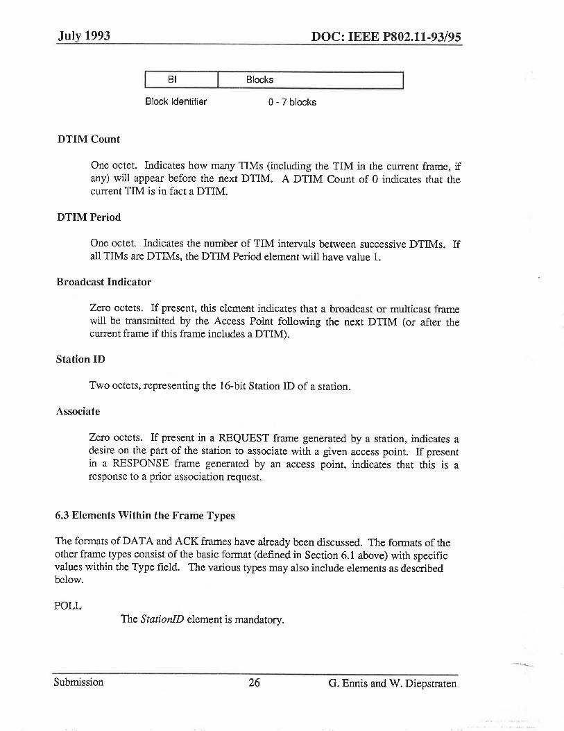
Block Group: Consists of a Block Identifier followed. by 0 through 7 Blocks.
Submission 25 G. Ennis and W. Diepstraten
July 1993 DOC: IEEE P802.11·93/95
BI Blocks
Block Identifier 0- 7 blocks
DTIM Count
One octet. Indicates how many TIMs (including the TIM in the current frame, if any) will appear before the next DTIM. A DTIM Count of 0 indicates that the current TIM is in fact a DTIM.
DTIM Period
One octet. Indicates the number of TIM intervals between successive DTIMs. If all TIMs are DTIMs, the DTIM Period element will have value 1.
Broadcast Indicator
Zero octets. If present, this element indicates that a broadcast or multicast frame will be transmitted by the Access Point following the next DTIM (or after the current frame if this frame includes a DTIM).
Station ID
Two octets, representing the 16-bit Station ID of a station.
Associate
Zero octets. If present in a REQUEST frame generated by a station, indicates a desire on the part of the station to associate with a given access point. If present in a RESPONSE frame generated by an access point, indicates that this is a response to a prior association request.
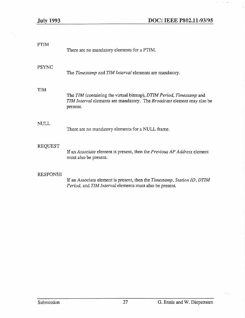
6.3 Elements Within the Frame Types
The formats of DATA and ACK frames have already been discussed. The formats of the other frame types consist of the basic format (defined in Section 6.1 above) with specific values within the Type field. The various types may also include elements as described below.
POLL The StationID element is mandatory.
Submission 26 G. Ennis and W. Diepstraten
July 1993
PTIM
PSYNC
TIM
NULL
REQUEST
RESPONSE
Submission
DOC: IEEE P802.11-93/95
There are no mandatory elements for a PTIM.
The Timestamp and TIM Interval elements are mandatory.
The TIM (containing the virtual bitmap), DTIM Period, Timestamp and TIM Interval elements are mandatory. The Broadcast element may also be present.
There are no mandatory elements for a NULL frame.
If an Associate element is present, then the Previous AP Address element must also be present.
If an Associate element is present, then the Timestamp, Station ID, DTIM Period, and TIM Interval elements must also be present.
27 G. Ennis and W. Diepstraten