JT8D POWERED AIRCRAFT NOISE BY ENGINE …...The refan concept is technically feasible and provides...
26
NASA TECHNICAL NASA TM X-71536 MEMORANDUM (NASA-TM-X-71 536 ) REDUCTI 0 N OF JT8D POBEED AICRA NOISE BY ENGINE7-33 SRE-ANNING (NASA) 26 p HC $4,5 0 CSCL 221 Unclas G3/28 38308 2E REDUCTION OF JT8D POWERED AIRCRAFT NOISE BY ENGINE REFANNING by L. E. Stitt and A. A. Medeiros Lewis Research Center Cleveland, Ohio TECHNICAL PAPER proposed for presentation at Air Transport Meeting sponsored by the Society of Automotive Engineers Dallas, Texas, April 30 - May 2, 1974 https://ntrs.nasa.gov/search.jsp?R=19740015229 2020-01-30T19:20:27+00:00Z
Transcript of JT8D POWERED AIRCRAFT NOISE BY ENGINE …...The refan concept is technically feasible and provides...

NASA TECHNICAL NASA TM X-71536MEMORANDUM
(NASA-TM-X-71 5 3 6 ) REDUCTI 0 N OF JT8DPOBEED AICRA NOISE BY ENGINE7-33SRE-ANNING (NASA) 26 p HC $4,50 CSCL 221
Unclas
G3/28 38308
2E
REDUCTION OF JT8D POWERED AIRCRAFT
NOISE BY ENGINE REFANNING
by L. E. Stitt and A. A. MedeirosLewis Research Center
Cleveland, Ohio
TECHNICAL PAPER proposed for presentation atAir Transport Meeting sponsored by theSociety of Automotive Engineers
Dallas, Texas, April 30 - May 2, 1974
https://ntrs.nasa.gov/search.jsp?R=19740015229 2020-01-30T19:20:27+00:00Z

REDUCTION OF JT8D POWERED AIRCRAFT NOISE BY ENGINE REFANNING
by L. E. Stitt and A. A. Medeiros
National Aeronautics and Space AdministrationLewis Research Center
Cleveland, Ohio
ABSTRACT
The purpose of the Refan Program is to establish the technical feasi-bility of substantially reducing the noise levels of existing JT8D poweredaircraft. This would be accomplished by retrofitting the existing fleetwith quieter refan engines and new acoustically treated nacelles. Nomajor technical problems exist that preclude the development and installa-tion of refanned engines on aircraft currently powered by the JT8D engine.The refan concept is technically feasible and provides calculated noisereductions of from 7 to 8 EPNdB for the B727-200 aircraft and from 10 to12 EPNdB for the DC-9-32 aircraft at the FAR Part 36 measuring stations.These noise levels are lower than both the FAR Part 36 noise standardsand the noise levels of the wide-body DC-10-10. Corresponding reductionsin the 90 EPNdB footprint area are estimated to vary from about 70 percentfor the DC-9 to about 80 percent for the B727. The refanned aircraftshould perform typical range/payload missions with a negligible effect onblock fuel. Production retrofit kits could be available in 1976 for theDC-9 at a unit cost of about $1.0 million and in 1977 for the B727 at aunit.cost of $1.7 million.
INTRODUCTION
Aircraft noise is one of today's significant environmental problems.High aircraft noise levels have resulted in limitations of airport expan-sions, airport curfews, civil law suits, restrictions in aircraft opera-tions, and a generally unfavorable reaction to airline operation at leastby residents of property surrounding airports. All of these are costlyto the airlines and their future growth.
The present airport noise environment is largely determined by thenoise output of the narrow-body aircraft which comprise about 75 percentof the domestic fleet of 2400 aircraft. The narrow-bodied fleet is madeup of aircraft powered by Pratt & Whitney (P&WA) JT3D and JT8D engines.These include about 600 B707 and DC-8's that utilize the JT3D and about1200 B727, B737, and DC-9's with JT8D engines. The JT8D powered aircraftare newer and are still in production in large quantities. It has beenestimated that the domestic fleet in 1985 will contain about 1600 JT8Dpowered aircraft and 400 JT3D powered aircrafts. Therefore, the reduc-tion of the noise of these aircraft will have a major impact on the over-all aircraft noise problem.

Solutions to the problem of aircraft noise generally fall into two
categories. The first category includes costly, long-range solutionsthat impose large economic burdens on the airlines and do nothing toprovide-a timely reduction in noise that will benefit all airportresidents. The solutions in the first category include: replacement ofexisting narrow-bodied aircraft with new, quieter aircraft; replacementof the engines in existing narrow-bodied aircraft with new quieter engines;procurement of land surrounding existing airports and relocating the af-fected population; or abandoning existing airports bounded by populousareas and relocating new airports in remote unpopulated areas.
The second category of solutions involves modifications to existingnarrow-body aircraft which can be achieved in a more timely and less ex-pensive manner than those in the first category. Two approaches havebeen identified in this category. One approach is to apply current soundsuppression technology to new nacelles for the JT3D and JT8D engines.The FAA has sponsored several programs directed to this approach thathave demonstrated the feasibility of meeting current FAR Part 36 require-ments for both JT3D and JT8D powered aircraft by the use of acousticallytreated nacelles. Nacelle treatment, however, cannot reduce the exhaustjet noise created outside of the nacelles. The jet noise, therefore, pro-vides a floor preventing any further reduction in noise.
In recognition of this limitation, the NASA, as part of the JointDOT/NASA aircraft noise reduction effort, has initiated a second approachwhich consists of modifications of the JT3D and JT8D engines to reducethe jet velocity in addition to application of nacelle noise suppression.The engine modification consists fundamentally of replacing the fan witha design configuration that provides both an increase in engine bypassratio and a reduction in fan source noise. This modification providesan opportunity to approach the noise characteristics of the popularly ac-cepted wide-body aircraft (DC-10, B747, and L1011) without developing anentirely new engine. This latter program, called the Refan Program, isthe subject of this paper.
REFAN PROGRAM OBJECTIVES, SCOPE, AND SCHEDULE
High interest was focused on an NASA Refan Program during late 1971and early 1972 through joint discussions with NASA, FAA, DOT, engine andairplane manufacturers and several airlines. As a result of these dis-cussions the Refan Program was officially initiated in August 1972 tomodify and quiet both the JT3D and JT8D powered aircraft. The objectiveof the Refan Program is to establish the technical feasibility of provid-ing a significant noise reduction for existing narrow-body aircraft to alevel below FAR Part 36. As an example, noise levels for two of the mostnumerous JT8D powered aircraft (B727-200 and DC-9-32) are shown in fig-ure 1 compared to both the FAR 36 noise standards and to the relativelyquiet wide-body DC-10-10. The noise levels of the narrow-body aircraftare significantly higher than FAR 36 for takeoff and approach, and arehigher than the heavier wide-body aircraft in all categories. It is de-

3
sirable to provide the same noise reduction below FAR 36 for the narrow-body jets as that provided by the wide-body aircraft. That is the goalof the Refan Program.
The scope of the Refan Program originally encompassed noise reduc-tion for all five of the commercial narrow-body aircraft powered by theJT3D and JT8D engines (B707, DC-8, B727, B737, and DC-9). Phase I con-tracts were let for design and analysis of the engine and nacelle modi-fications with three major contractors: Pratt & Whitney Aircraft (a divi-sion of United Aircraft Corp.), The Boeing Commercial Airplane Company (adivision of the Boeing Co.), and the Douglas Aircraft Company (a divisionof McDonnell Douglas Corp.). Contracts were also let with American Air-lines and United Airlines for consulting work to assure that the modifica-tions being considered incorporated as many of the user airlines' require-ments as possible.
In January 1973, program funding curtailment forced limitation ofthe scope of the program to only one engine. The joint NASA/DOT/FAA de-cision was to proceed with the JT8D engine rather than the JT3D. Thisengine was selected since the aircraft it powers comprise about 60 per-cent of the domestic airline fleet and accounts for over 70 percent ofthe takeoffs and landings. These aircraft are more modern than the olderJT3D fleet, and over 100 new aircraft are on order by the airlines. Re-duction of the noise of this fleet of aircraft would, therefore, have thelargest favorable impact on airport noise exposure in the 1980's.
There was no technical reason for discontinuing further work on theJT3D. The preliminary design work on the engine had been completed, andthe refanned engine appeared to be a low technical risk development. In-tegration studies of the new engines on both the B707 and DC-8 had alsobeen completed and revealed no significant problems in implementing aretrofit of these aircraft.
Budget constraints also required a reduction in the scope of theflight tests for the JT8D powered aircraft. The minimal changes requiredfor the DC-9 airplane and its corresponding lower flight demonstrationcosts compared to the B727 and B737 aircraft, permitted negotiation of acontract culminating in a flight demonstration for the DC-9 in early 1975.Concurrently, ground test noise and performance evaluation for a refannedB727 side engine nacelle and a B727 center engine installation will beperformed. While a ground test program at Boeing is not as desirable asa flight test program for the Boeing aircraft, this approach appears tobe technically sound because of:
1. Similarity of the B727 side engine installation with that of theDC-9 for which both ground and flight test data will be obtained.
2. Extensive Boeing experience and statistical data to predictground-to-flight noise levels and aircraft performance from ground tests.
The Refan Program is currently in Phase II of a two-phase program.

Phase I, concluded in July 1973, provided definition of engine, nacelle,and aircraft modifications, preliminary retrofit and economic analyses,and wind tunnel tests of the refanned DC-9, as shown in the schedule infigure 2. The current Phase II will complete the program which will in-clude ground tests of the B727 side engine nacelle and center engine in-stallation and a flight demonstration of a DC-9 with refanned engines andacoustic nacelles early in 1975. Most of the design effort has now beencompleted and a rather extensive model test program had been conducted atThe Boeing Company in support of the refanned B727 aircraft. The firstrefanned JT8D-109 engine was run by P&WA at the end of February 1974.Engine acoustic and performance testing will continue throughout the cur-rent year. Aircraft modifications for the proposed DC-9 flight demon-strator have been designed and fabricated and are currently being in-stalled on this aircraft on the production line. Nacelle components havealso been designed for the DC-9 and B727 and fabrication has been initi-ated. Engineering mockups of the refanned JT8D-109 engine have been pro-vided to both aircraft manufacturers by P&WA to assist in the design andinstallation of nacelle components and aircraft supplied subsystems.
TECHNICAL APPROACH
The overall approach to achieving lower engine noise is to replacethe existing low-bypass-ratio engine two-stage fan with a larger singlestage fan designed with low noise features. The hardware and generaloperating characteristics of the core engine are maintained while provid-ing a new higher bypass ratio engine. The energy to drive the larger fanis extracted from the low pressure turbine which reduces both the jet ve-locity and jet noise. The increased tip speed of the fan required tomaintain fan pressure ratio results in noise levels which will requireeffective fan and duct acoustic treatment. Since the engine features afull-length fan duct there is a favorable amount of surface area avail-able for treatment. The inlet and tailpipe of the new nacelles provideadditional surface area for sound treatment. The refanned engine with ahigher bypass ratio provides an increase in takeoff thrust and a reduc-tion in cruise TSFC for the uninstalled engine which helps offset the per-formance losses associated with the larger treated nacelles.
Engine and airframe modifications are limited to those changes thatwill make the engines quieter. For the engine, the changes will belimited to the fan (including fan stage and static parts) , the fan-driveturbine, exhaust nozzles and engine nacelle with acoustic treatment. Nomodifications will be made to other engine or airframe components unlessthey can be shown to be necessary or to contribute directly and substan-tially to the reduction of noise. These limitations are required to mini-mize the cost of retrofit, and retain, to the largest extent possible,the proven reliability of the JT8D engine.

Engine Modifications
Engine modifications were determined as a result of extensive cyclestudies conducted by Pratt & Whitney Aircraft for the JT8D engine. Fig-ure 3 shows a comparison of the existing and refanned JT8D engines andtable I compares the major performance characteristics of the two config-urations. The two-stage fan, with closely spaced blade rows, is replacedby a single-stage fan with approximately two-chord spacing between bladerows, as shown in figure 3. The core engine pressure ratio and weightflow capabilities are maintained by the use of two super-charging stagesin the core flow path in front of the low pressure compressor. Theseadded stages restore the pressure rise that was lost by eliminating thesecond fan stage. Full-span IGV's are used and the stage is straddle-mounted with the IGV's supporting the front bearing. The IGV's are spacedseveral chord lengths forward of the rotor to reduce blade interactionnoise and acoustic treatment is applied between the IGV's and the fanrotor. The fan diameter is increased about 8.7 inches, from 40.5 to49.2 inches, and the bypass ratio is nearly doubled from 1.05 to 2.03.
The existing low and high pressure compressors and .the high pressureturbine do not require modification. The three-stage low pressure tur-bine will not require any change in diameter or blade chord, but the lastrotor blading is restaggered to permit increased work absorption whileretaining essentially the same level of efficiency.
Design of the fan duct acoustic treatment (fig. 4) is based on ananalytical procedure developed at P&WA. The acoustic treatment providedin the outer wall of the engine flowpath between the inlet guide vaneand the fan was designed to attenuate tone noise which is present in theinlet noise spectra over most of the normal engine operating range. Alsoshown in figure 4 is the liberal use of acoustic treatment in the fanduct to reduce the levels of aft-propagating fan noise. The backing depthtreatment was selected with a peak attenuation frequency in the 1/3 octaveband below the blade passage frequency corresponding to approach powersetting. In all cases, the treatment consists of aluminum perforatedplate on aluminum honeycomb core.
The production JT8D has a full-length bypass duct with the core flowand bypass flow entering a common tailpipe (provided by the airframe manu-facturer) to provide some natural mixing of the hot and cool streams.Performance tests of the production engine indicate that some mixing ofthe two streams is attained and thus there is a reduction in jet velocityand noise compared to an unmixed engine. The same tailpipe mixing effec-tiveness is assumed for the refanned engine so that the larger amount ofcool bypass flow has a greater effect in reducing jet velocity than forthe production engine. The mixed jet velocity at takeoff power is esti-mated to be reduced from 1470 to 1140 fps.
6
Nacelle Modifications
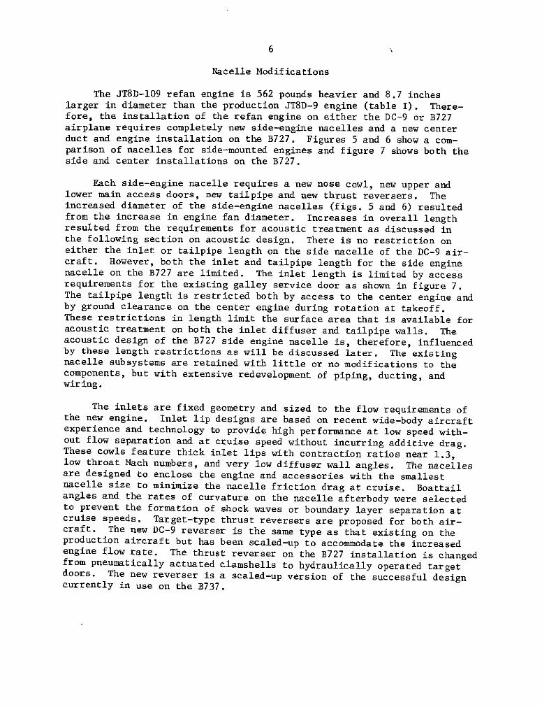
The JT8D-109 refan engine is 562 pounds heavier and 8.7 incheslarger in diameter than the production JT8D-9 engine (table I). There-fore, the installation of the refan engine on either the DC-9 or B727airplane requires completely new side-engine nacelles and a new centerduct and engine installation on the B727. Figures 5 and 6 show a com-parison of nacelles for side-mounted engines and figure 7 shows both theside and center installations on the B727.
Each side-engine nacelle requires a new nose cowl, new upper andlower main access doors, new tailpipe and new thrust reversers. Theincreased diameter of the side-engine nacelles (figs. 5 and 6) resultedfrom the increase in engine fan diameter. Increases in overall lengthresulted from the requirements for acoustic treatment as discussed inthe following section on acoustic design. There is no restriction oneither the inlet or tailpipe length on the side nacelle of the DC-9 air-craft. However, both the inlet and tailpipe length for the side enginenacelle on the B727 are limited. The inlet length is limited by accessrequirements for the existing galley service door as shown in figure 7.The tailpipe length is restricted both by access to the center engine andby ground clearance on the center engine during rotation at takeoff.These restrictions in length limit the surface area that is available foracoustic treatment on both the inlet diffuser and tailpipe walls. Theacoustic design of the B727 side engine nacelle is, therefore, influencedby these length restrictions as will be discussed later. The existingnacelle subsystems are retained with little or no modifications to thecomponents, but with extensive redevelopment of piping, ducting, andwiring.
The inlets are fixed geometry and sized to the flow requirements ofthe new engine. Inlet lip designs are based on recent wide-body aircraftexperience and technology to provide high performance at low speed with-out flow separation and at cruise speed without incurring additive drag.These cowls feature thick inlet lips with contraction ratios near 1.3,low throat Mach numbers, and very low diffuser wall angles. The nacellesare designed to enclose the engine and accessories with the smallestnacelle size to minimize the nacelle friction drag at cruise. Boattailangles and the rates of curvature on the nacelle afterbody were selectedto prevent the formation of shock waves or boundary layer separation atcruise speeds. Target-type thrust reversers are proposed for both air-craft. The new DC-9 reverser is the same type as that existing on theproduction aircraft but has been scaled-up to accommodate the increasedengine flow rate. The thrust reverser on the B727 installation is changedfrom pneumatically actuated clamshells to hydraulically operated targetdoors. The new reverser is a scaled-up version of the successful designcurrently in use on the B737.

7
Nacelle Acoustic Design
The success of the refan concept relies to a great extent on theability to design effective acoustic treatment in the nacelle such thatthe suppressed noise levels for the inlet and tailpipe are balanced andat the desired values.
DC-9 aircraft. - Definition of the detailed acoustic treatment inthe inlet and tailpipe of the DC-9 nacelle is based on Douglas predictionmethods and Pratt & Whitney Aircraft-supplied engine cycle parameters.An acoustic design chart, based on approach conditions, was used to selecttreatment lengths that provide a balanced configuration for equal inletand aft fan flyover noise. The resulting acoustic treatment area for theDC-9 nacelle configuration is shown in figure 5. All inlet acoustictreatment is perforated aluminum sheet bonded to an aluminum honeycombcore. Welded steel and Inconel construction is used in the tailpipe.The details of the acoustic treatment were based on empirical data fromDC-9 flyover noise tests, JT8D static engine tests, and laboratory flowduct transmission loss tests.
The length of the DC-9 refan inlet was selected to provide sufficientacoustic area to meet the noise goals without the need of a splitter ringor treated engine nose dome. The inlet treatment was designed to givemaximum EPNL attenuation at the fan fundamental passage frequency(3150 Hz) at approach power setting. Multiple pure tone or buzzsaw noisecaused by the high tip speeds of the refanned JT8D-109 engine was notconsidered by the inlet treatment design because sections of thick treat-ment between the IGV's and the rotor are tuned for buzzsaw noise and aresupplied with the engine case (fig. 4). However, design provisions havebeen made to change the inlet acoustical treatment if subsequent testingshows that additional buzzsaw treatment is required.
Tailpipe length on the DC-9 nacelle was selected to provide suffi-cient acoustic treatment area to meet the noise goals. The tailpipetreatment was optimized with all of the treatment tuned to the secondharmonic (6300 Hz) of the blade passage frequency at approach power set-ting.
B727 aircraft. - Treatment design parameters were obtained usinglining design computer programs in which nacelle internal geometry, aero-dynamic and acoustic parameters are input. The selected lining parameterswere then used to predict the component attenuations achieved by the var-ious lining design configurations using a noise-prediction program. Thedesign point for the inlet, duct and tailpipe acoustic treatment is theapproach condition and is aimed for maximum attenuation at the fan funda-mental passage frequency.
Since the inlet length of the side engine nacelle is limited, addi-tional surface area for acoustic treatment is provided by a long treatedengine nose dome and a treated inlet ring as shown in figure 6. Thesesurfaces are constructed of polyimide bonded fiberglass honeycomb, faced

with a porous woven skin and backed with a nonporous skin. The acousticring has a double-faced acoustic panel of polyimide construction. Threemounting struts support the ring and carry anti-icing air to the ring.
At this point in the program, there has not been a firm decision onwhether the inlet ring is required in the refanned B727 inlet. For theB727 ground test program the inlet ring will be designed to be removableso that the acoustic benefits of the ring can be determined during groundtests. Buzzsaw treatment, other than that between the IGV's and the fanrotor, if required, could be installed in the inlet immediately upstreamof the IGV to efficiently attenuate buzzsaw noise.
Since the tailpipe length of the side engine nacelle is limited,additional treatment area is provided by a long flow divider between thefan and core flow as shown in figure 6. The tailpipe treatment includesperipheral acoustic lining on the outer wall and on both surfaces of theprimary/fan flow splitter. The splitter is fabricated of a layer ofInconel 625 honeycomb adjacent to the primary flow and a layer of titaniumhoneycomb adjacent to the fan duct. The tailpipe is also fabricated fromtitanium honeycomb. The outside surface of the splitter and the tailpipeperiphery are lined for fan noise attenuation at the fan fundamental pas-sage frequency at approach power setting. The inside surface of thesplitter is lined for high-frequency turbine noise attenuation.
A description of the acoustic lining in the B727 center duct is pro-vided in figure 8. The treatment configuration is perforated aluminumsheet over a honeycomb core of epoxy/fiberglass structure. Treatmentareas near the engine (S-1 and S-2) are directed at reducing the buzzsawnoise while treatment area further forward (S-3 through S-5) reduces fanblade row interaction noise.
Aircraft Modifications
Changes to the basic airframe associated with installation of thelarger and heavier nacelles consist of minor aerodynamic and structuralmodifications to the pylon and fuselage for the side engines of both theDC-9 and B727. New side engine mounts are required to accommodate theincreased weight and nacelle diameter. The refan pylon for the DC-9 wasreduced in span from 16.75 to 8.05 inches. For this airplane it was de-sirable to install the larger refan nacelle closer to the fuselage tominimize the effects on deep stall and engine out minimum control speeds.
Major modifications to the B727 airframe structure are associatedwith the installation of the enlarged S-duct and center engine (fig. 7).This rework will involve considerable alteration to several body bulk-heads and frames to permit installation of the larger inlet duct. Newengine mounts will be installed to accommodate the heavier and largerengine. New mount supports are required and local reinforcement added todistribute the load into the primary fin structure.

The major portion of the structural changes affect the aft body sec-tion of the airframe in the area of attachment of the new nacelles. Thereare no major changes to the forward body or wing structure except forminor reinforcement of body structure because of increased fuselage bend-ing and installation of ballast to balance the added weight of the refannacelle. The installation of the JT8D-109 refan engine results in anoperational empty weight (OEW) increase of 2482 pounds for the DC-9 air-craft and 3660 pounds for the B727 aircraft.
PERFORMANCE PREDICTIONS
The JT8D refan program engine modifications are designed to reducethe jet noise by cycle changes which remove energy from the jet exhaustand transfer this work to the fan. Fan noise is then effectively sup-pressed by both engine case and nacelle acoustic treatment. Detailednoise estimates including spectra and flyover time histories have beenmade by the contractors. The results of these analyses were combinedwith estimated aircraft performance to determine noise levels at FARPart 36 measuring stations and EPNL noise contours. In addition, engineand aircraft performance predictions were made.
Acoustic Performance
Perceived noise levels. - As indicated previously, the JT8D refannoise reduction strategy involves the reduction of the dominant jet andfan noise components. This is accomplished by the cycle change to reducejet velocity and by fan design changes coupled with acoustic treatment.A summary of the aircraft manufacturer noise component analysis for cur-rent production and refanned aircraft is shown in figure 9(a) for theB727-200 and in figure 9(b) for the DC-9-32. These bar charts displaythe maximum tone corrected perceived noise levels, PNLTmax, contributedby each of five components (fan inlet, fan exhaust, low-frequency core, jetand high-frequency turbine) at the FAR 36 approach and takeoff measure-ment points. The total noise signature is also shown for each condition.Engine thrusts and aircraft altitudes for production and refan aircraftvary in a manner appropriate to the execution of an approach on a 3-degreeglide slope and takeoff with a FAR 36 cutback certification profile.
For the B727 (fig. 9(a)), refanning and acoustic treatment substan-tially reduced the offending fan inlet and exhaust noise and the jetnoise generated by the primary exhaust during both approach and takeoff.Low-frequency core noise is predicted to remain at roughly the same levelas the production estimate and becomes the dominant source after refanning.High-frequency turbine noise does not contribute significantly for refantakeoff. Low-frequency core noise generation and transmission processesare poorly understood at present, and isolation of that component is dif-ficult. Refan acoustic tests will emphasize core noise determination.
A qualitatively similar situation with respect to fan and jet com-

10
ponents is shown in figure 9(b) for the DC-9. However, estimated core
levels do not dominate after refanning, and turbine noise is the largestcontributor at approach.
Integration of the flyover noise histories based on the sum of thecomponent analysis results in the predicted refan FAR 36 effective per-ceived noise levels (EPNL's) shown in figure 10. Refan levels are com-pared to the production aircraft levels, the corresponding FAR 36 stand-ards, and the wide-body DC-10-10 data shown previously in figure 1. Thesenoise estimates show that the refanned aircraft have a considerable poten-tial for realizing significant reduction in community noise levels. Therefanned B727-200 aircraft provides reductions of 7 to 8 EPNdB comparedto the production aircraft, while corresponding reductions for the DC-9-32are 10 to 12 EPNdB. In addition, the refan noise levels have been reducedbelow FAR Part 36 requirements by 5 to 11 EPNdB for the DC-9-32 and by 3to 13 EPNdB for the B727-200. Compared to the relatively quiet wide-bodyDC-10-10, the refan aircraft are quieter by at least 31 EPNdB at all ofthe measuring points.
Noise contour area. - Noise contour areas provide a more completeindication of community exposure and the noise reduction benefits of re-fanning. EPNL noise contours have been calculated for the production andrefanned aircraft. The resulting areas of these contours have been sum-marized as a function of EPNL contour level for the DC-9-32 and B727-200aircraft in figures 11 and 12, respectively. These areas were calculatedfor a FAR 36 cutback certification takeoff profile and a single segmentapproach on a 3-degree glide slope. Estimates of DC-10-10 contour areasare also included for comparison. Note that a full power takeoff profilewas used for the DC-10 to agree with the way the FAR 36 certificationlevels were measured for this aircraft.
The refanned aircraft provide substantial reductions in contour areacompared to the production aircraft. For example, at the 90 EPNdB level,area reductions of about 70 and 80 percent are indicated for the DC-9 andB727, respectively. Both refanned aircraft expose smaller areas than theDC-10-10 for levels greater than 90 EPNdB.
Installed Engine Performance
The calculated performance of the JT8D-109 refan engine and the pro-duction JT8D-9 engine installed on both the DC-9-32 and B727-200 aircraftis compared in table II in terms of takeoff thrust and cruise thrust spe-cific fuel consumption (TSFC). All performance estimates are based ondata supplied by Pratt & Whitney Aircraft for a fuel lower heating valueof 18 400 Btu/lb. Installation effects include those losses resultingfrom internal flow in the inlet and tailpipe and the effect of bleed andpower extraction. External drag changes are considered in airplane per-formance calculations.
At takeoff, the installed takeoff thrust of the refan engine is about
11
5 percent higher than the production engine at a Mach number of 0.27. Atcruise, the refan engine provides an improvement in uninstalled TSFC com-pared to the production engine. However, increased internal losses negatemost of that gain so that the installed cruise TSFC's are all nearlyequivalent for refan and production engines.
Airplane Performance
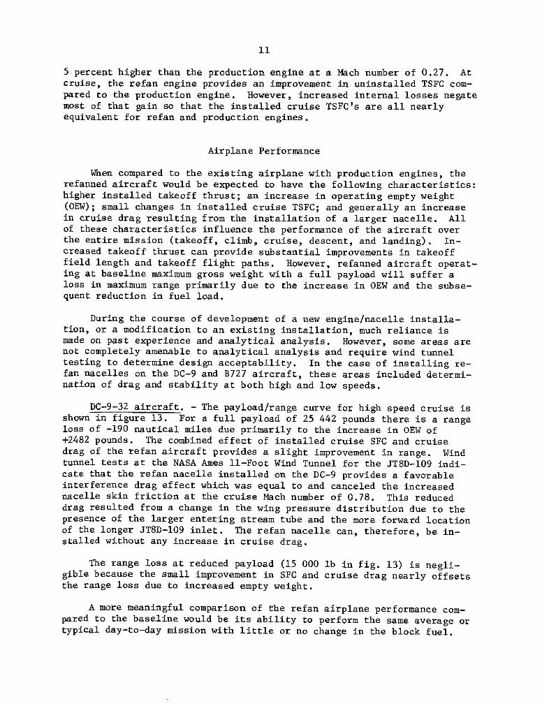
When compared to the existing airplane with production engines, therefanned aircraft would be expected to have the following characteristics:higher installed takeoff thrust; an increase in operating empty weight(OEW); small changes in installed cruise TSFC; and generally an increasein cruise drag resulting from the installation of a larger nacelle. Allof these characteristics influence the performance of the aircraft overthe entire mission (takeoff, climb, cruise, descent, and landing). In-creased takeoff thrust can provide substantial improvements in takeofffield length and takeoff flight paths. However, refanned aircraft operat-ing at baseline maximum gross weight with a full payload will suffer aloss in maximum range primarily due to the increase in OEW and the subse-quent reduction in fuel load.
During the course of development of a new engine/nacelle installa-tion, or a modification to an existing installation, much reliance ismade on past experience and analytical analysis. However, some areas arenot completely amenable to analytical analysis and require wind tunneltesting to determine design acceptability. In the case of installing re-fan nacelles on the DC-9 and B727 aircraft, these areas included determi-nation of drag and stability at both high and low speeds.
DC-9-32 aircraft. - The payload/range curve for high speed cruise isshown in figure 13. For a full payload of 25 442 pounds there is a rangeloss of -190 nautical miles due primarily to the increase in OEW of+2482 pounds. The combined effect of installed cruise SFC and cruisedrag of the refan aircraft provides a slight improvement in range. Windtunnel tests at the NASA Ames 11-Foot Wind Tunnel for the JT8D-109 indi-cate that the refan nacelle installed on the DC-9 provides a favorableinterference drag effect which was equal to and canceled the increasednacelle skin friction at the cruise Mach number of 0.78. This reduceddrag resulted from a change in the wing pressure distribution due to thepresence of the larger entering stream tube and the more forward locationof the longer JT8D-109 inlet. The refan nacelle can, therefore, be in-stalled without any increase in cruise drag.
The range loss at reduced payload (15 000 lb in fig. 13) is negli-gible because the small improvement in SFC and cruise drag nearly offsetsthe range loss due to increased empty weight.
A more meaningful comparison of the refan airplane performance com-pared to the baseline would be its ability to perform the same average ortypical day-to-day mission with little or no change in the block fuel.
12
This comparison is shown in table III(a) for two ranges and two payloads
at the DC-9 high speed cruise of Mach 0.78. All of these missions can be
performed by the refan airplane with about one percent decrease in block
fuel compared to the production airplane.
A low speed wind tunnel test was also conducted in the NASA Ames
12-Foot Wind Tunnel to assess the effects of the larger refan nacelles on
the stability and control characteristics, with emphasis on the deepstall regime. Various pylons of reduced span were tested. Results indi-
cate that deep stall recovery characteristics are nearly independent of
pylon span and are acceptable with no additional design changes required.
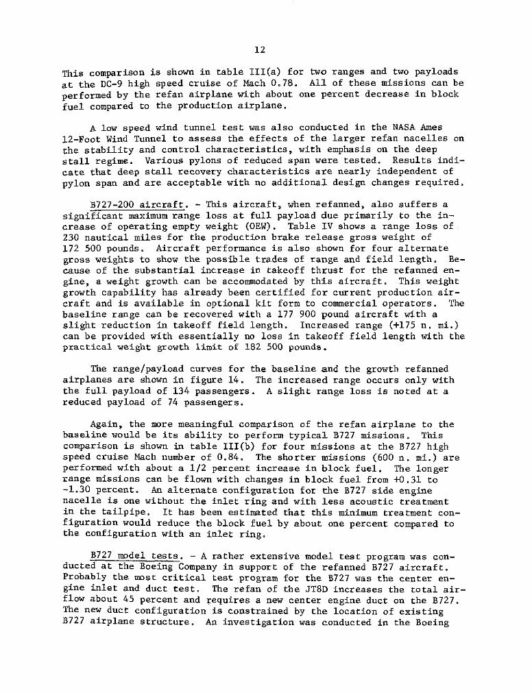
B727-200 aircraft. - This aircraft, when refanned, also suffers asignificant maximum range loss at full payload due primarily to the in-crease of operating empty weight (OEW). Table IV shows a range loss of230 nautical miles for the production brake release gross weight of172 500 pounds. Aircraft performance is also shown for four alternategross weights to show the possible trades of range and field length. Be-cause of the substantial increase in takeoff thrust for the refanned en-gine, a weight growth can be accommodated by this aircraft. This weightgrowth capability has already been certified for current production air-craft and is available in optional kit form to commercial operators. Thebaseline range can be recovered with a 177 900 pound aircraft with aslight reduction in takeoff field length. Increased range (+175 n. mi.)can be provided with essentially no loss in takeoff field length with thepractical weight growth limit of 182 500 pounds.
The range/payload curves for the baseline and the growth refannedairplanes are shown in figure 14. The increased range occurs only withthe full payload of 134 passengers. A slight range loss is noted at areduced payload of 74 passengers.
Again, the more meaningful comparison of the refan airplane to thebaseline would be its ability to perform typical B727 missions. Thiscomparison is shown in table III(b) for four missions at the B727 highspeed cruise Mach number of 0.84. The shorter missions (600 n. mi.) areperformed with about a 1/2 percent increase in block fuel. The longerrange missions can be flown with changes in block fuel from +0.31 to-1.30 percent. An alternate configuration for the B727 side enginenacelle is one without the inlet ring and with less acoustic treatmentin the tailpipe. It has been estimated that this minimum treatment con-figuration would reduce the block fuel by about one percent compared tothe configuration with an inlet ring.
B727 model tests. - A rather extensive model test program was con-ducted at the Boeing Company in support of the refanned B727 aircraft.Probably the most critical test program for the B727 was the center en-gine inlet and duct test. The refan of the JT8D increases the total air-flow about 45 percent and requires a new center engine duct on the B727.The new duct configuration is constrained by the location of existingB727 airplane structure. An investigation was conducted in the Boeing

13
9' x 9' Low Speed Wind Tunnel to evaluate the pressure recovery and dis-tortion characteristics of the refan center engine inlet and duct. Anextensive test program was conducted which included an evaluation of manyvortex generator and flow control device configurations. Excellent re-sults in terms of pressure recovery and distortion were obtained. A vor-tex generator pattern was developed that results in greater control overairflow distortions at less pressure loss at all airplane operating con-ditions than previously experienced. At this time it would appear thatthere will be no center engine duct compatibility problems with the refanengine.
Flight control evaluations at low speed were conducted at BoeingVertol and at the University of Washington Aero Lab. Results indicatethat the airplane longitudinal characteristics with the refan nacellesare not significantly different from the production airplane. Some smallreduction in directional stability was measured but rudder effectivenesswas not affected.
A high speed configuration development test program was conducted inthe CALSPAN Transonic Wind Tunnel. A nacelle shape was identified suchthat the inlet cowl, nose dome and side cowls can be interchangeable forleft and right hand installations. Installation of the larger refannacelles on the B727 resulted in a favorable interference drag at thecruise Mach number. The magnitude of this interference effect was equalto and offset the increased friction drag of the larger nacelles. The re-fanned nacelles can, therefore, be installed on this aircraft without anyincrease in cruise drag.
RETROFIT KIT COSTS
The costs of refanning the JT8D powered aircraft are estimated to beabout $1.0 million for the DC-9 and about $1.7 million for the B727.These costs include the P&WA engine kit, new nacelles, new pylons, fuse-lage modifications, and installation charge. In addition to the kitcosts, additional costs would be incurred for spares, crew training, andlost revenue over the period that the aircraft would be out of service.The DC-9 retrofit is relatively straight forward and out-of-service timeis estimated to be about 16 days. The B727, with the more difficultcenter engine installation, would require about 21 days to retrofit. Theimpact of retrofit on cash trip costs (crew, fuel, insurance and mainte-nance) would be minor.
The total cost of retrofitting the entire domestic JT8D powered fleetis estimated at $3.3 billion, which includes an initial investment of$1.85 billion for the engine and airplane kits and their installation.To put the total cost in the perspective of airline revenue, it is equiva-lent to a one-percent increase in cost for domestic passengers and cargoapplied over 8.5 years. If program go-ahead is assumed to be June 1975,first kit delivery could be in 1976 for the DC-9 and in 1977 for the B727.Program completion could be targeted for June 1980, assuming a retrofitof 395 domestic DC-9's and 669 B727 aircraft.

14
CONCLUDING REMARKS
The Refan Program is currently in its second and final phase. Thisphase will feature ground tests of the Boeing 727-200 side engine nacelleand center engine installation early in 1975. A flight demonstration ofa Douglas DC-9 with refanned engines and nacelles will also be conductedearly in 1975. At the present time no major technical problems have beenidentified that would preclude installation of the JT8D-109 refan engineon either the DC-9 or the B727 airplanes.
Substantial noise reduction using the refan concept is technicallyfeasible and provides estimated noise reductions of from 7 to 8 EPNdB forthe B727 and 10 to 12 EPNdB for the DC-9 at the FAR 36 measuring stations.These noise levels are lower than either the FAR-Part 36 noise standardsor the noise levels of the wide-body DC-10-10. Corresponding reductionsin the 90-EPNdB footprint area vary from about 70 percent for the DC-9 toabout 80 percent for the B727.
Improvements in refanned engine performance can: offset the losses inaircraft performance from nacelle treatment and added empty weight. Boththe refanned DC-9 and B727 aircraft can perform typical range/payloadmissions with a negligible effect on block fuel compared to the produc-tion airplane.
The unit price of a refan kit for retrofit is estimated to be fromabout $1 million for the DC-9 to $1.7 million for the B727. Productionkits could be available in 1976 for the DC-9 and in mid-1977 for the B727aircraft. Finally, the increased thrust of the refan engine makes it acandidate for future production models of both the DC-9 and B727 aircraft.
BIBLIOGRAPHY
1. Callaghan, J. T., Donelson, J. E., and Morelli, J. P.: The Effects onCruise Drag of Installing Long-Duct Refan-Engine Nacelles on theMcDonnell Douglas DC-8-50 and -61. NASA CR-121218, May 1973.
2. Callaghan, J. T., Donelson, J. E., and Morelli, J. P.: The Effects onCruise Drag of Installing Refan-Engine Nacelles on the McDonnellDouglas DC-9. NASA CR-121219, May 1973.
3. Chrisenberry, H. E., Doss,.Po G., Kressly, A. E., Prichard, R. D., andThorndike, C. S.: The Results of a Low-Speed Wind Tunnel Test toInvestigate the Effects of Installing Refan JT8D Engines on theMcDonnell Douglas DC-9-30. NASA CR-121220, June 1973.
4. Douglas Aircraft Company: DC-9/JT8D Refan Phase I, Final Report.NASA CR-121252, November 1973.

15
5. Shirkey, M. D.: The Results of Low-Speed Wind Tunnel Tests toInvestigate the Effects of the NASA Refan JT8D Engine Nacelles onthe Stability and Control Characteristics of the Boeing 727-200.NASA CR-134503, October 1973.
6. Kaldschmidt, G., Syltebo, B. E., and Ting, C. T.: 727 Airplane CenterDuct Inlet Low-Speed Performance Confirmation Model Test for RefannedJT8D Engines. Phase II. NASA CR-134534, November 1973.
7. Kupcis, E. A.: The Results of a High-Speed Wind Tunnel Test toInvestigate the Effects of the NASA Refan JT8D Engine Nacelles onthe Stability and Control Characteristics of the Boeing 727 Airplane.NASA CR-134545, December 1973.
8. Easterbrook, W. G. and Carlson, R. B.: Cruise Drag Results From HighSpeed Wind Tunnel Tests of NASA Refan JT8D Engine Nacelles on theBoeing 727-200. NASA CR-134546, December 1973.

TABLE I. - COMPARISON OF PRODUCTION JT8D-9 AND
REFAN JT8D-109 ENGINES
Parameter Production Refan
Fan 2-stage 1-stageInlet guide vanes Yes YesFan diameter, in. 40.5 49.2Inlet diameter, in. 42.5 54.5Length, in. 120 134Engine weight (dry), lb 3218 3780Total airflow, SLTO, lb/sec 319 467Fan pressure ratio 1.97 1.67Fan tip speed at TO, ft/sec 1420 1600Bypass ratio 1.05 2.03Cycle temperature, OF 1870 1863Primary jet velocity, ft/sec 1766 1445Mixed jet velocity, ft/sec 1470 1140
Uninstalled performance
Thrust, SLS, lb 14 500 16 600T.O. thrust (M = 0.27), lb 12 450 13 325Maximum cruise thrust 4540 4720
(M = 0.80 at 35 000 ft), lbMaximum cruise TSFC 0.802 0.770
(M = 0.80 at 35 000 ft),lb/hr/lb

TABLE II. - INSTALLED ENGINE PERFORMANCE
(a) Takeoff thrust, lb (M = 0.27 at sea level)
DC-9-32 B727-200
Production Refan Production Refan
Uninstalled thrust 12 450 13 325 12 450 13 325
Installed thrust 12 300 12 900 12 050 12 600
(b) Cruise TSFC, lb/hr/lb (Alt = 30 000 ft)
DC-9-32 B727-200(M = 0.78 at (M = 0.84 at
FN = 3600 lb) FN = 4000 ib)
Production Refan Production Refan
Uninstalled TSFC 0.788 0.760 0.786 0.774
Installed TSFC .806 .805 .813 .812
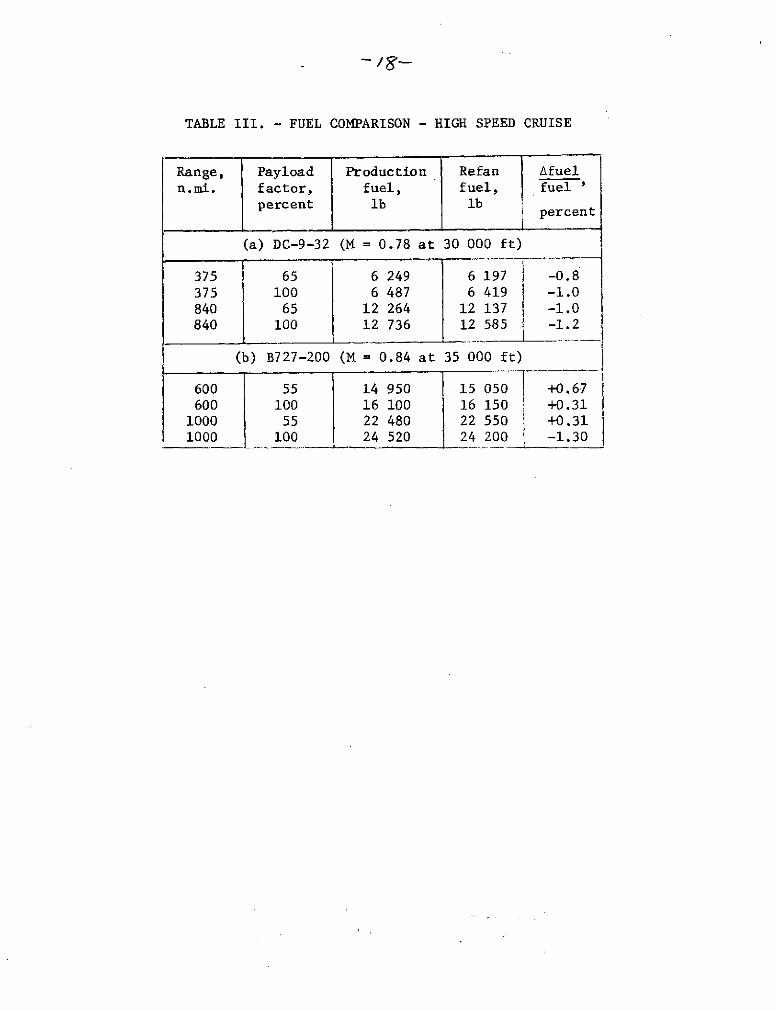
TABLE III. - FUEL COMPARISON - HIGH SPEED CRUISE
Range, Payload Production Refan Afueln.mi. factor, fuel, fuel, fuel '
percent lb lb percentpercent
(a) DC-9-32 (M = 0.78 at 30 000 ft)
375 65 6 249 6 197 -0.8375 100 6 487 6 419 -1.0840 65 12 264 12 137 -1.0840 100 12 736 12 585 -1.2
(b) B727-200 (M = 0.84 at 35 000 ft)
600 55 14 950 15 050 +0.67600 100 16 100 16 150 1 +0.31
1000 55 22 480 22 550 +0.311000 100 24 520 24 200 -1.30

TABLE IV. - PERFORMANCE OPTIONS, B727-200 JT8D-109
ENGINE REFAN CONFIGURATION
INCREMENT FROM BASELINEWEIGHT VARIATIONS BRGWTO ACHIEVE: (LB) AOEW ,ARANGE ATAKEOFF
(LB) (NMI) FIELD LENGTH(FT)
BASELINE BRGW 172,500 + 3,660 - 230 - 1,300
BASELINE T.O. FIELDLENGTH 181,000 + 3,820 + 135 0
BASELINE RANGE 177,900 + 3,820 0 - 800
PRACTICAL WEIGHT 182,000*GROWTH (182,500)
BASELINE BLOCK FUEL 177.000 + 3,820 - 40 - 900
* BASELINE AIRPLANE: JT8D-9MAX TAXI WT = 173,000 LBMAX BR REL WT = 172,500 LBOEW = 99,000 LBMAX FUEL CAPACITY = 7,680 U.S. GAL
* BASELINE PERFORMANCE: ATA RANGE = 1,355 NMIT.O. FIELD LENGTH = 8,370 FT
* TAKEOFF CONDITIONS: SEA LEVEL840 FA/C ON
* CRUISE CONDITIONS: M = .84 AT 30,000 FTPAYLOAD = 134 PASS. (27,470 LB)STANDARD DAYZERO WINDATA DOMESTIC RESERVES
NOTE: FUEL CAPACITY OF GROWTH OPTIONS IS INCREASED TO 7,780 U.S. GAL.*FUEL CAPACITY LIMITED FOR THIS PAYLOAD

PRODUCTION JT8D-9r TWO FAN STAGES
r FOUR LOW COMPRESSOR STAGES
i { ENGINE- -
SINGLE / / ENGINE CORE COMMON AFT OFSTAGE / Ii THIS LINE EXCEPT AS STATEDFAN NEW 4TH STAGE BLADE
TWO ADDITIONAL LOW COMPRESSOR STAGES REVISED FLANGE "M'
REFAN JT8D-109CD-11670
SOLID AREAS ON CASINGS INDICATE ACOUSTIC TREATMENT
Figure 3. - Engine comparison.
ENGINE _
FAN CASE
FAN DUCT
FAN DUCT ESTIMATED EF-LOCATION FECTIVE AREA,
FT2
1 11.752 8.53 66.74 8.2
FAN CASE LENGTH, IN.FWD 6.5AFT 6. 2
Figure 4. - P8WA supplied acoustic treatment.
PRODUCTION NACELLE - JT8D-9
203 IN.
DMAX 53 IN.
DMAX = 64 IN.
261 IN.
REFAN NACELLE - JT8D-109INLET TREATMENT ' TAILPIPE TREATMENTEFFECTIVE AREA = 51.0 FT2 EFFECTIVE AREA = 50.5 FT2
CD-11669Figure 5. - Douglas DC-9 nacelle comparison.

110 - SIDELINE
O FAR 36 LIMIT
SPRODUCTION AIRCRAFT100-
0
DC 9-32 8727-200 DC 10-10
CUTBACK APPROACH110 -
9_ -
DC 9-32 B 727-200 DC 10-10 DC 9-32 B 727-200 DC 10-10
Figure. 1. - Existing Far Part 36 noise levels for productionaircraft.
1972 1973 1974 1975
PHASE I '
PHASE IIP & WA JT8D-109
DEFINITION tDESIGNMOCKUPMANUFACTURECOMPONENT TESTSENGINE TESTS
BOEING 727-200DEFINITIONDESIGNMODEL TESTSMOCKUPMANUFACTURE ___"___
GROUND TESTSDOUGLAS DC 9-32
DEFINITIONDESIGNMODEL TESTSMOCKUPMANUFACTUREAIRCRAFT MODSFLIGHT TESTS
Figure 2 - JT8D refan program schedule.

PRODUCTION NACELLE - JT8D-9215 IN.
DMA X = 50 IN.
DMAX = 62 IN.
2331 N.L INLET TREATMENT REFAN NACELLE - JT8D-109 t TAILPIPE TREATMENT
EFFECTIVE AREA 60. 5 FT2 EFFECTIVE AREA = 62 1 FT2
DIFFUSER - 28.8 FT2 TAILPIPE - 45.9 FT2
RING - 27. 0 FT2 SPLITTER - 16. 2 FT2
NOSE DOME - 4.7 FT2
CD-11668
Figure 6. - Boeing 727 side-engine nacelle comparison.
r- NEW FAIRINGS - REVISED ENGINE/ NEW CENTER DUCT7 \ SUPPORT STRUCTURE
NEW INLET- -- -", //
NEW INLET & "/ NEWNOSE DOME-, EXHAUST
SYSTEM 7
NEW SIDE COWLS
\-EXISTING GALLEY /SERVICE DOOR
S LMODIFIED V-NEW COWL PANELSMODIFIED TAIL SKID- - / VERTICAL
NEW EXHAUST SYSTEM FIREWALL AND CD-11671
Figure 7. - JT8D-109 installation on B 727-200.

/-S-4 PERFORATEDALUMINUM SKINEPOXY/FIBERGLASSSTRUCTURE
DUCT EFFECTIVELOCATION AREA, ,S-2
FT2 -S-1
S-1 22. 5S-2 56.4 BUZZSAWS-3 41.6 FAN TONE- /
S-4 25.9S-5 66. 5
BUZZ SAW-'
Figure 8. - B 727 acoustic lining description - center-engine inlet
120] PRODUCTION
- _ REFAN
110 - 0-
L LU
II I
100 - " -
90 -I N
APPROACH TAKEOFF (CUTBACK)(b) DC 9-32AIRCRAFT.
Figure 9. -Conponent noise levels at Far 36 measurement points.
I
U-
Figure 9. -Conponent noise levels jat Far 36 measurement points.

110 - SIDELINE
[ FAR 36 LIMIT
N PRODUCTION AIRCRAFT
100 - REFAN AIRCRAFT
w 90
S80DC 9-32 B727-200 DC 10-10
110 - TAKEOFF (CUTBACK) APPROACHCL
100
90
DC 9-32 B727-200 DC 10-10 DC 9-32 B727-200 DC 10-10
Figure 10 - Comparison of predicted refan noise levels with Far Part 36and production aircraft.
20 40O DC-10-10 (FULL O DC-10-10 (FULL
POWER TAKEOFF) POWER TAKEOFF)10 - 2
O 8
6 - C 10
4 -6
PRODUCTION2 - PRODUCTION
S2
.8- REFAN\ 1S.i REFAN'
.6 \ .
.4 J.4 I I I I l l85 90 95 100 105 110 85 90 95 100 105 110EFFECTIVE PERCEIVED NOISE EFFECTIVE PERCEIVED NOISE
LEVEL EPNdB LEVEL EPNdB
Figure 11. - DC-9-32 footprint contour Figure 12. - B 727-200 footprintareas. Cutback certification profile. contour areas. Cutback certifi-Single segment approach. cation profile. Single segment
approach.

ENGINES O.E.W.
- JTBD-9 59,076 LBWT LIMITED PAYLOAD --- JT8D-109 61,558 LB
3027,924 LB
25115 PASSENGERS PLUS BAGGAGE
20
75 PASSENGERS PLUS BAGGAGE
15TOTA -- - - - *** - - ---- ----- --- v
o COMPOINTS AFFCTING jM. I. W)
0 500 1000 1500 2000
Figure 13. - DC-9-32 payload range. 0, 78 Mach number, 30 000 ft
FUELBRGW, LB CAPACITY, CEW, LB
U.S. .GAL
BASELINE 172,500 7,680 99,000REFAN CONFIG 182,500 7,781000 102820 1500 2000
40 -MAX LANDING WT
MAX Z.F.W.
30 M = .84 @ 30,000 FT
ZERO WIND- IATA DOMESTIC
< RESERVES> 20 BASELINE ENGINE
\ JT8D-974 PASSENGERS (55% PAYLOAD FACTOR) _ REFAN ENGINE
\ JT8D-109
10 -
0 5 10 15 20ATA RANGE, 100 NMI
Figure 14. - B 727-200 payload range comparison.