JT15D ATA 75
12
Pratt & Whitney JT15D Series (CAT C) ATA 75 – ENGINE AIR Page 1 of 12 FOR TRAINING PURPOSES ONLY © JT15D - ISSUE 1, 2009
Transcript of JT15D ATA 75

7/27/2019 JT15D ATA 75
http://slidepdf.com/reader/full/jt15d-ata-75 1/12
Pratt & Whitney JT15D Series (CAT C)
ATA 75 – ENGINE AIR
Page 1 of 12 FOR TRAINING PURPOSES ONLY © JT15D - ISSUE 1, 2009

7/27/2019 JT15D ATA 75
http://slidepdf.com/reader/full/jt15d-ata-75 2/12
Pratt & Whitney JT15D Series (CAT C)
ATA 75 – ENGINE AIR
Page 2 of 12 FOR TRAINING PURPOSES ONLY © JT15D - ISSUE 1, 2009
ATA 75 – ENGINE AIR
0 TABLE OF CONTENTS
1 Secondary air system 31.1 General 32 Turbine cooling and air bleed 52.1 General 52.2 Operation 52.3 Maintenance 63 Bearing compartment sealing 73.1 Purpose 73.2 Description 73.3 Maintenance 73.4 Symptoms of labyrinth seal problems 84 Anti-icing system 94.1 Purpose 94.2 Operation 95 Stator anti-icing valve 115.1 Purpose 115.2 Construction 115.3 Operation 115.4 Maintenance 11
7/27/2019 JT15D ATA 75
http://slidepdf.com/reader/full/jt15d-ata-75 3/12
Pratt & Whitney JT15D Series (CAT C)
ATA 75 – ENGINE AIR
Page 3 of 12 FOR TRAINING PURPOSES ONLY © JT15D - ISSUE 1, 2009
1 SECONDARY AIR S YSTEM
1.1 General
Of all the air entering the engine core, 25% isused in the combustion process; theremaining 75% is used by the secondary air system.
1.1.1 The secondary air system provides air pressure to:
Cool hot section parts
Seal bearing compartments
Operate the fuel control unit and flowdivider valve
Anti-ice the inlet cone and compressor front inner stator
Cabin air bleed
7/27/2019 JT15D ATA 75
http://slidepdf.com/reader/full/jt15d-ata-75 4/12
Pratt & Whitney JT15D Series (CAT C)
ATA 75 – ENGINE AIR
Page 4 of 12 FOR TRAINING PURPOSES ONLY © JT15D - ISSUE 1, 2009
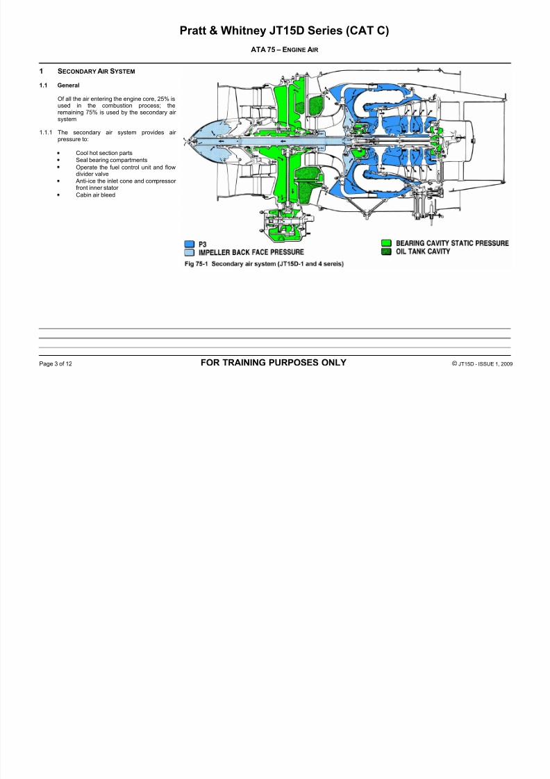
1.1.2 Two sources of air are used in the secondary air system:
Impeller back face pressure
Compressor delivery pressure (P3)
1.1.3 This section is divided into 3 parts:
1 Turbine cooling and air bleed system2 Bearing compartment sealing3 Anti-ice system
7/27/2019 JT15D ATA 75
http://slidepdf.com/reader/full/jt15d-ata-75 5/12
Pratt & Whitney JT15D Series (CAT C)
ATA 75 – ENGINE AIR
Page 5 of 12 FOR TRAINING PURPOSES ONLY © JT15D - ISSUE 1, 2009
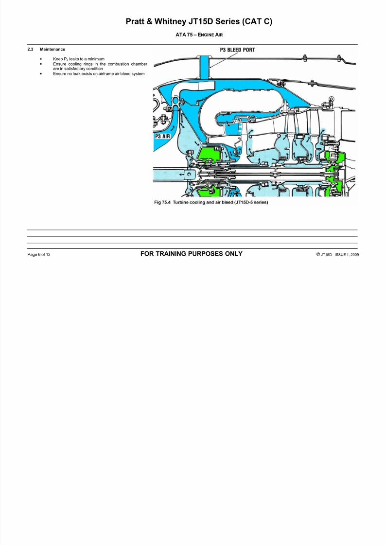
2 TURBINE COOLING AND AIR BLEED
2.1 General
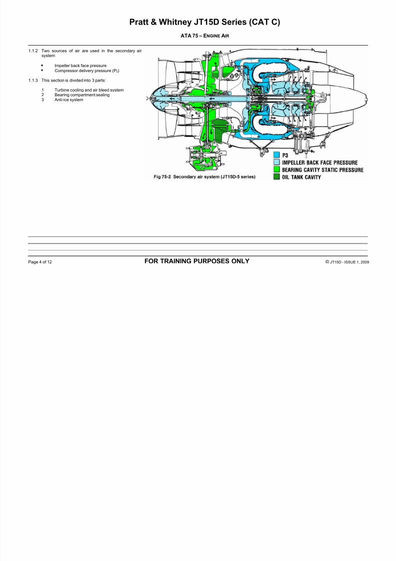
Internal passages in the engine, guide P3 andimpeller back face air pressure for cooling of various hot section components like;- combustion chamber,- turbines and- turbine stators.
P3 air is tapped from the gas generator case for airframe application.
2.2 Operation
P3 and impeller back face air pressure aredirected with various baffles to provide cooling
and prolong hot section components life. Oncethe air has been used for cooling, it isevacuated in the gas path.
7/27/2019 JT15D ATA 75
http://slidepdf.com/reader/full/jt15d-ata-75 6/12
Pratt & Whitney JT15D Series (CAT C)
ATA 75 – ENGINE AIR
Page 6 of 12 FOR TRAINING PURPOSES ONLY © JT15D - ISSUE 1, 2009
2.3 Maintenance
Keep P3 leaks to a minimum
Ensure cooling rings in the combustion chamber
are in satisfactory conditionEnsure no leak exists on airframe air bleed system
7/27/2019 JT15D ATA 75
http://slidepdf.com/reader/full/jt15d-ata-75 7/12
Pratt & Whitney JT15D Series (CAT C)
ATA 75 – ENGINE AIR
Page 7 of 12 FOR TRAINING PURPOSES ONLY © JT15D - ISSUE 1, 2009
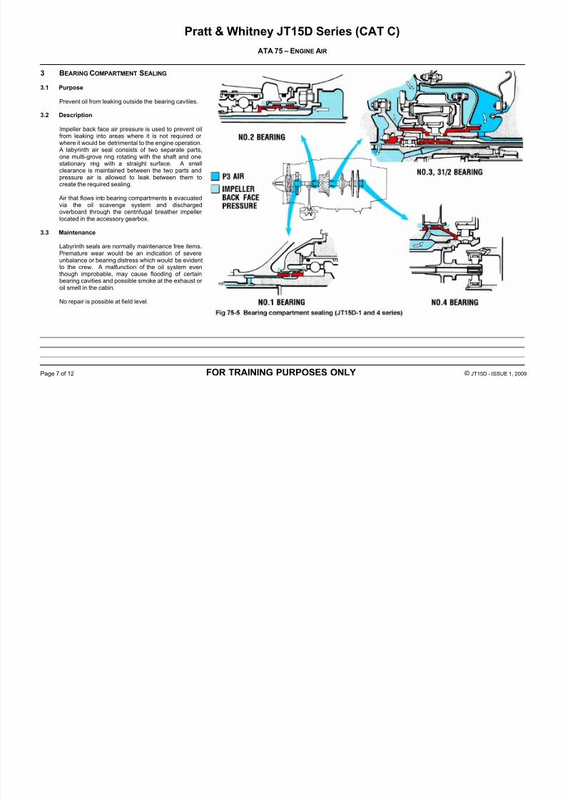
3 BEARING COMPARTMENT SEALING
3.1 Purpose
Prevent oil from leaking outside the bearing cavities.
3.2 Description
Impeller back face air pressure is used to prevent oilfrom leaking into areas where it is not required or where it would be detrimental to the engine operation.
A labyrinth air seal consists of two separate parts,one multi-grove ring rotating with the shaft and onestationary ring with a straight surface. A smallclearance is maintained between the two parts andpressure air is allowed to leak between them tocreate the required sealing.
Air that flows into bearing compartments is evacuatedvia the oil scavenge system and dischargedoverboard through the centrifugal breather impeller located in the accessory gearbox.
3.3 Maintenance
Labyrinth seals are normally maintenance free items.Premature wear would be an indication of severeunbalance or bearing distress which would be evidentto the crew. A malfunction of the oil system eventhough improbable, may cause flooding of certainbearing cavities and possible smoke at the exhaust or oil smell in the cabin.
No repair is possible at field level.
7/27/2019 JT15D ATA 75
http://slidepdf.com/reader/full/jt15d-ata-75 8/12
Pratt & Whitney JT15D Series (CAT C)
ATA 75 – ENGINE AIR
Page 8 of 12 FOR TRAINING PURPOSES ONLY © JT15D - ISSUE 1, 2009
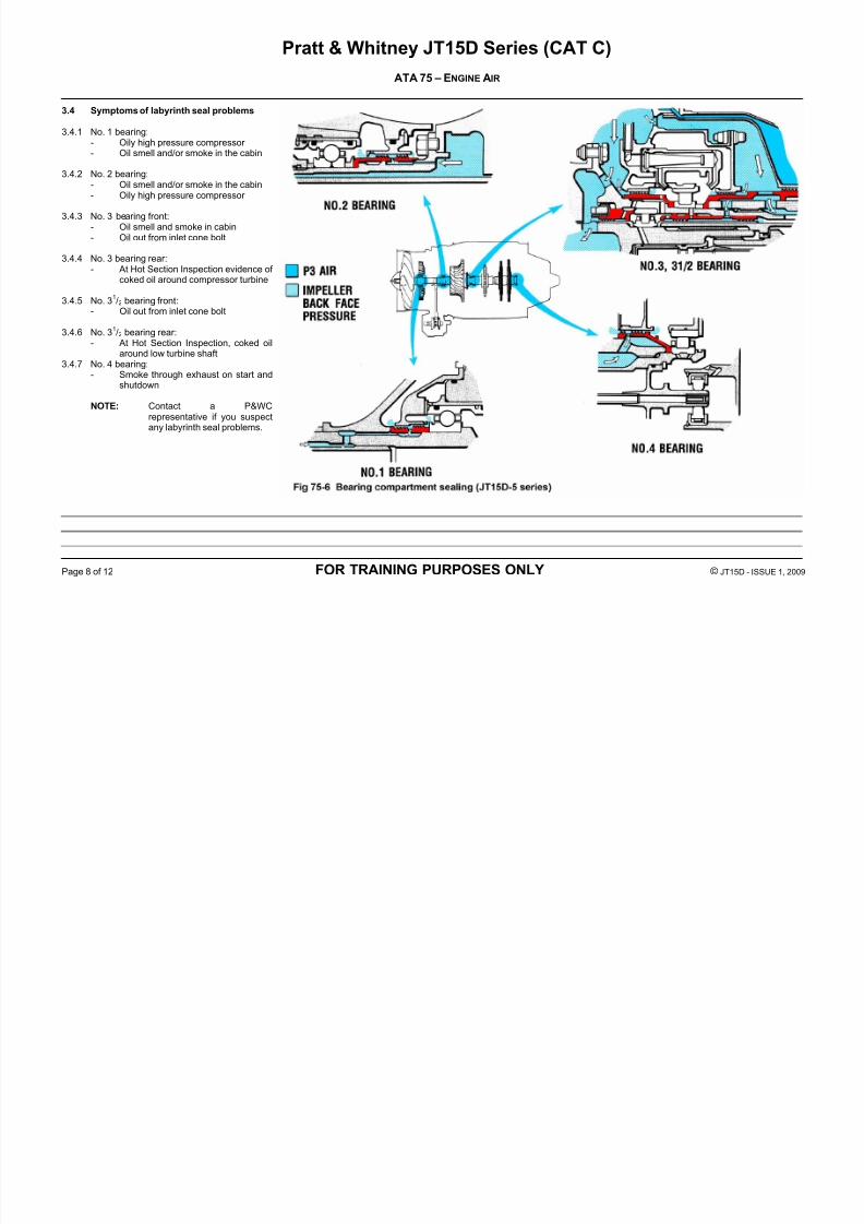
3.4 Symptoms of labyrinth seal problems
3.4.1 No. 1 bearing:- Oily high pressure compressor
- Oil smell and/or smoke in the cabin
3.4.2 No. 2 bearing:- Oil smell and/or smoke in the cabin- Oily high pressure compressor
3.4.3 No. 3 bearing front:- Oil smell and smoke in cabin- Oil out from inlet cone bolt
3.4.4 No. 3 bearing rear:- At Hot Section Inspection evidence of
coked oil around compressor turbine
3.4.5 No. 31
/2 bearing front:- Oil out from inlet cone bolt
3.4.6 No. 31/2 bearing rear:
- At Hot Section Inspection, coked oilaround low turbine shaft
3.4.7 No. 4 bearing:- Smoke through exhaust on start and
shutdown
NOTE: Contact a P&WCrepresentative if you suspectany labyrinth seal problems.

7/27/2019 JT15D ATA 75
http://slidepdf.com/reader/full/jt15d-ata-75 9/12
Pratt & Whitney JT15D Series (CAT C)
ATA 75 – ENGINE AIR
Page 9 of 12 FOR TRAINING PURPOSES ONLY © JT15D - ISSUE 1, 2009
4 ANTI-ICING S YSTEM
4.1 Purpose
Prevent ice formation that could possibly damage theengine core if ingested. The following areas are anti-iced:
Inlet cone and cone bolt
Compressor front inner stator
T1 inlet thermocouple housing
4.2 Operation
The inlet cone is heated by the impeller back face air pressure flowing through the fan shaft. The inlet conedouble wall construction (JT15D-1, 4 and 5A) or single wall(JT15D-5D) allows hot air to flow rearward where it isdischarged via holes into the cone cavity. The air pressure
in the cone cavity is routed to the no. 1 bearing labyrinthseal. A small amount of the air that passes through the fanshaft is discharged through the inlet cone bolt.
7/27/2019 JT15D ATA 75
http://slidepdf.com/reader/full/jt15d-ata-75 10/12
Pratt & Whitney JT15D Series (CAT C)
ATA 75 – ENGINE AIR
Page 10 of 12 FOR TRAINING PURPOSES ONLY © JT15D - ISSUE 1, 2009
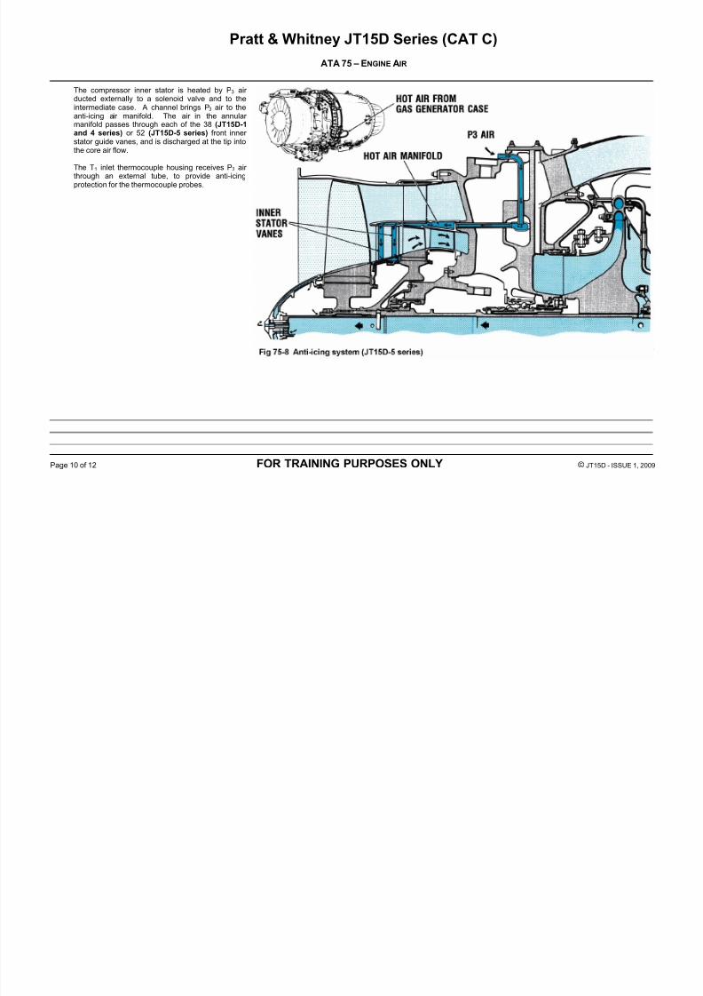
The compressor inner stator is heated by P3 air ducted externally to a solenoid valve and to theintermediate case. A channel brings P3 air to theanti-icing air manifold. The air in the annular
manifold passes through each of the 38 (JT15D-1and 4 series) or 52 (JT15D-5 series) front inner stator guide vanes, and is discharged at the tip intothe core air flow.
The T1 inlet thermocouple housing receives P3 air through an external tube, to provide anti-icingprotection for the thermocouple probes.
7/27/2019 JT15D ATA 75
http://slidepdf.com/reader/full/jt15d-ata-75 11/12
Pratt & Whitney JT15D Series (CAT C)
ATA 75 – ENGINE AIR
Page 11 of 12 FOR TRAINING PURPOSES ONLY © JT15D - ISSUE 1, 2009
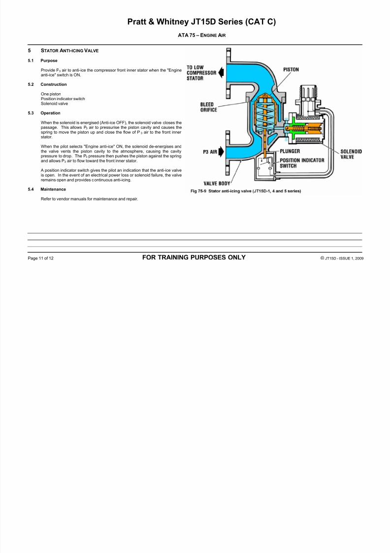
5 STATOR ANTI-ICING VALVE
5.1 Purpose
Provide P3 air to anti-ice the compressor front inner stator when the "Engineanti-ice" switch is ON.
5.2 Construction
One pistonPosition indicator switchSolenoid valve
5.3 Operation
When the solenoid is energised (Anti-ice OFF), the solenoid valve closes thepassage. This allows P3 air to pressurise the piston cavity and causes thespring to move the piston up and close the flow of P 3 air to the front inner
stator.
When the pilot selects "Engine anti-ice" ON, the solenoid de-energises andthe valve vents the piston cavity to the atmosphere, causing the cavitypressure to drop. The P3 pressure then pushes the piston against the springand allows P3 air to flow toward the front inner stator.
A position indicator switch gives the pilot an indication that the anti-ice valveis open. In the event of an electrical power loss or solenoid failure, the valveremains open and provides continuous anti-icing.
5.4 Maintenance
Refer to vendor manuals for maintenance and repair.

7/27/2019 JT15D ATA 75
http://slidepdf.com/reader/full/jt15d-ata-75 12/12
Pratt & Whitney JT15D Series (CAT C)
ATA 75 – ENGINE AIR
Page 12 of 12 FOR TRAINING PURPOSES ONLY © JT15D - ISSUE 1, 2009
PAGE INTENTIONALLY LEFT BLANK