JRC - JRL-2000F user manual€¦ · JRL-2000F J l lntake vent 1t Front ~ 15 cm min. • Use a...
67
813111 Downloaded by RadioManuai.EU
Transcript of JRC - JRL-2000F user manual€¦ · JRL-2000F J l lntake vent 1t Front ~ 15 cm min. • Use a...

831~11dVVI 813111 ~Ii
Downloaded by RadioManuai.EU

INTRODUCTION ~
Thank you for purchasing the JRL-2000F, the world's first MOSFET HF linear amplifier. JRC has dssigned and produced the JRL-2000F based on its many years of achievements and experience with professional transmitters and has taken advantage of the latest design technology. Piease read this manual carefully before operating your new amplifier. The JRL-2000F has been manufactured under the strictest quality control conditions. Should you find any darnage to the amplifier or encounter any other problems, contact your dealer or nearest JRC representative.
A cc ESSQ R I ES\ Each JRL-2000F is shipped with the followtng accessories
• lnstruction manual ...................................................................................................... , .................. 1 • Remote Control Unit (NCH-365) ................... -. ............................................................................. 1 • Main fuse (15A) ............................................................................................................................. 2 • Power amplifier unit fuse (15A) ................................................................................................... 2 • Control cable plug and plug casing .................................................. : ....................................... 1 • Dry cell batteries for remote control .......................................................................................... 2
Piease check to make sure that all of the above items were received with your JRL-2000F.
I
Downloaded by RadioManuai.EU

CONTENTS \ 1. FEATURES ............................................................................................................................... 1
2. SPECIFICATIONS .................................................................................................................... 3
3. BEFORE USING THE JRL-2000F ....................................................... , .................................... 4 3.1 Installation Location ........................................................................................................... 4 3.2 Power Supply ..................................................................................................................... 4 3.3 Exciters .............................................................................................................................. 5 3.4 Antennas ............................................................................................................................ 5 3.5 Grounding .......................................................................................................................... 5
4. CONNECTION .......................................................................................................................... 6 4.1 Connection to a JST-135 transceiver ................................................................................. 7
4.1.1 Connection diagram ............................................................................................... 7 4.1.2 Control cabl!;l wiring diagram ................................................................................. 8
4.2 Connection to a Non-JRC Exciter ...................................................................................... 9 4.2.1 Connection diagram ............................................................................................... 9 4.2.2 Control cable wiring diagram ............................................................................... 10
5. OPERATING CONTROLS AND FUNCTIONS ....................................................................... 14 5.1 Front Panel Controls ........................................................................................................ 14 5.2 Rear Panel Controls ......................................................................................................... 15 5.3 Remote Control Uni! (NCH- 365) ..................................................................................... 16
6. BASIC OPERATION ............................................................................................................... 17 6.1 Preparation ...................................................................................................................... 17 6.2 Operation Modes ............................................................................. ; ............................... 17
6.2.1 Operation of the POWER SUPPLY CONT. switch ................................................ 18 6.2.2 Antenna switch mode ........................................................................................... 18 6.2.3 Antenna tuner mode ............................................................................................. 19 6.2.4 Linear amplifier mode ........................................................................................... 20
6.3 Automatie Tuning Operation ............................................................................................ 21 6.3.1 Automatie tuning procedures ............................................................................... 22 6.3.2 JRL-2000F band assignment table ...................................................................... 24
6.4 SET Operation .................................................................................................................. 25 6.5 Switching Antennas .... , .................................................................................................... 27 6.6 Adjusting the ALC Level .................................................................................................. 28 6.7 Memory Backup ......................................... , ..................................................................... 30 6.8 Precautions ...................................................................................................................... 31
7. SPECIAL OPERATIONS ........................................................................................................ 32 7.1 Erasing Preset Data ......................................................................................................... 32
7 .1.1 Erasing all data for a selected antenna ................................................................ 32 7 .1.2 Erasing all data for a selected frequency band .................................................. 32
7.2 Write-protecting for Preset Data ...................................................................................... 33 7.3 Using the JRL-2000F as a Dummy Load ......................................................................... 33 7.4 Using More than 4 Antennas ........................................................................................... 34 7.5 Setting the DIP Switches .................................................................................................. 35
8. PROTECTION FUNCTIONS ................................................................................................... 36 8.1 Cooling Fans .................................................................................................................... 36 8.2 Gauses of Alarms and Corrective Measures ................................................................... 36
II Downloaded by RadioManuai.EU

9. PRECAUTIONS FOR MAINTENANCE AND OPERATION ................................................... 38 9.1 Cleaning the Main Unit ................................................................................................... 38 9.2 Maintenance of the Interna! Circuits ............................................................................... 39 9.3 Radio lnterference Precautions ...................................................................................... 39 9.4 Precautions Against Power Surge Caused by Lightening .............................................. 39
10. PROBLEM SOLVING ............................................................................................................. 40 1 0.1 After-sales Service ................................................................................................... , ...... 40 10.2 Troubleshooting .............................................................................................................. 40
11. OPTIONS ................................................................................................................................ 41
12. ATTACHED DIAGRAMS ........................................................................................................ 42 12.1 External View .................................................................................................................. 42 12.2 Block Diagram ................................................................................................................ 42 12.3 Connection Diagrams ..................................................................................................... 42
III
Downloaded by RadioManuai.EU

1 FEATURES
e 48 RF Power MOSFETs
The power amplifier unit is equipped with 4 wide-band amplifier circuits (2SK408/2SK409), each incorporating 12 high-voltage resistant RF power MOSFETs. As output gain is achieved by electrically combining the output from these broad-band amplifiers, sufficient output margin is available so that high-quality full duty cycle output throughout the entire power range is possible.
• SEPP-type Low Distorfion Power Amplifier
Single ended push-pull (SEPP) circuits are employed. SEPP circuits do not have any of the shortcomings of conventional transistor-type push-pull circuits, so the JRL-2000F obtains high output power with superior IMD chracteristics.
• Fully Automatie Antenna Tuner The JRL-2000F is equipped with a fully automatic, instantly switching antenna tuner which converts the composite elements in the matehing circuit to the binary system. By storing matehing data for each antenna in the amp's high-capacity memory, antenna matehing can be done instantaneously.
• Automatie Antenna Seleetor Up to four antennas can be connected and selected by front panel switches. The selected antenna setting can be stored in memory along with the matehing data for the antenna tuner to allow instant QSY.
e Automatie Frequeney Counter System
A built-in frequency counter automatically reads the frequency of the input signal from the exciter and selects the correct frequency band. Manual band changing is not required and any exciter can be used with the JRL-2000F.
• High-Effieieney Switehing Power Supply with PFC
The power supply for the JRL-2000F is equipped with a Power Factor Corrector (PFC) which corrects the AC input waveform to a sine wave by using the active smoothing circuit method. This increases the AC line power factor, which previously attained only 50-60%, to almost 100%. This means that power consumption has been nearly halved compared to other conventional power supplies. With its high-efficiency MOSFET switching regulator, a maximum continuous power supply output of 2.4 kW can be achieved when this exceptionally powerful unit is connected to 220 - 240V AC.
• Low Noise Design
The power amplifier and the power supply unit are equipped with MOSFETs which have higher heat-resistance properties. This reduces the operating time of the cooling fans significantly. A low noise axial fan mounted in the rear or the chasis also contributes to noise reduction. Additionally, a full break-in circuit with a compact relay housed in a shielded case reduces relay operating noise.
·1-Downloaded by RadioManuai.EU

1 FEATURES
• Various Protection Circuits
The JRL-2000F incorporates several protection facilities in order to protect the circuitry against internal and external stresses and overloads such as overdrive and abnormal output Ioads. When one of the protection circuits is actuated in the PA unit, the gate bias of the power MOSFETs are directly controlled, without slow-operating ALC feedback, in order to reduce the power output. Therefore, should the ALC line not be conected, the PA unit will not suffer any damage.
Downloaded by RadioManuai.EU
2 SPECIFICATIONS
Operating frequency bands
Rated output power
Output impedance Harmonics Intermodulation distortion (IMD) Input impedance Exciting power Frequency switching time Power supply voltage Power consumption Input power factor Temperature range
Protection circuits
Dimensions Weight
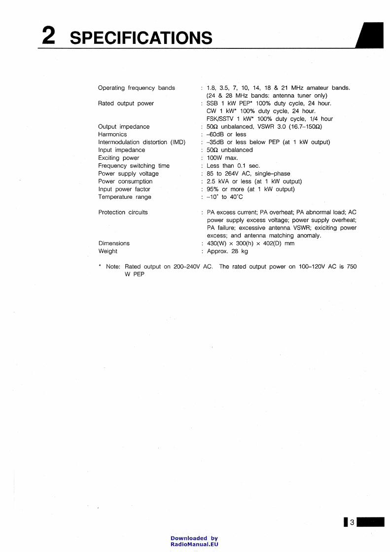
1.8, 3.5, 7, 10, 14, 18 & 21 MHz amateur bands. (24 & 28 MHz bands: antenna tuner only) SSB 1 kW PEP* 100% duty cycle, 24 hour. CW 1 kW* 100% duty cycle, 24 hour. FSK/SSTV 1 kW* 100% duty cycle, 1/4 hour 50n unbalanced, VSWR 3.0 (16.7-150!2) -60dB or less -35dB or less below PEP (at 1 kW output) 50Q unbalanced 100W max. Less than 0.1 sec. 85 to 264V AC, single-phase 2.5 kVA or less (at 1 kW output) 95% or more (at 1 kW output) -10· to 4o·c
PA excess current; PA overheat; PA abnormal Ioad; AC power supply excess voltage; power supply overheat; PA failure; excessive antenna VSWR; exiciting power excess; and antenna matehing anomaly. 430(W) X 300(h) X 402(0) mm Approx. 28 kg
* Note: Rated output on 200-240V AC. The rated output power on 100--120V AC is 750 W PEP
·3-Downloaded by RadioManuai.EU

3 BEFORE USING THE JRL-2000F
3.1 Installation Location When determining a location for installing the JRL-2000F, please take the following criteria into consideration: • Avoid a place that is exposed to direct sunlight or susceptible to overheating. • Avoid humid or dusty places. • Do not place containers holding water or other liquids above or on top of the JRL-2000F. • The JRL-2000F draws cooling air in from the front panel and expels it from the rear. Therefore,
do not place any objects within 15 cm of the front and rear panels of the amplifier.
Outlet vent ~ Rear ~ 15 cm min.
JRL-2000F
J l
lntake vent 1t Front ~ 15 cm min.
• Use a sturdy table or plattarm that can easily support the weight of the JRL-2000F (approximately 28 kg).
3.2 Power Supply Requirements
-4·
The JRL-2000F consumes approximately 12A of electrical current at an output power of 1000 W when power is supplied at 220 VAC. This must be taken into consideration, along with the consumption of the exciter, accessories and other home appliances, when choosing an AC line of sufficient capacity.
For full 1 kW outputpower a 200--240 VAC line must be used. lf a 100--120 VAC line is used, the maximum rated RF output power is 750W.
lf the power outlet has a ground terminal, be sure that the black wire is connected to ground.
Downloaded by RadioManuai.EU
BEFORE USING THE JRL-2000F 3
3.3 Exciters Any HF-band transmitter or transceiver with a 50Q RF output impedance can be used as an exciter for the JRL-2000F. When used with the Japan Radio Co. JST-135 HF transceiver, additional control features can be utilized to enhance automatic band changing and tuning.
lf the maximum output of the exciter exceeds 100W, the over-current protection circuit in the power supply unit may be activated and the output waveform may be distorted. Therefore, it is necessary to connect an external ALC signal in order to control the exciter output.
3.4 Antennas lt is recommended that you select antenna(s) that meet the following criteria: • Antenna impedance is 50n. • When using a beam or vertical antenna equipped with trap coils or balun transformers,
be sure that they are capable of handling at least 1.5 kW PEP input. • Use a coaxial cable with sufficient current capacity for all antenna Connections. • lf the antenna VSWR value is too high the antenna wave radiation factor drops. Also, in
case of a mismatch of the coaxial cable and antenna, undesired RF radiation may occur, possibly causing radio interference. Therefore, special care must be taken in order to avoid these problems.
3.5 Grounding To prevent electric shock and interference with other devices, connect your JRL-2000F and all other radio devices to a proper external grounding system. Use the heaviest possible copper wire, braid or strap and follow the shortest possible route. Do not use any gas pipe, water pipe or cable duct as a ground.
ls-Downloaded by RadioManuai.EU

4 CONNECTION
-6·
Before connecting the JRL-2000F to an exciter, turn oft the power of each radio device and unplug all power cords from the outlets.
Different methods of connection are used for different types of exciters. lnterfacing the exciter to the JRL-2000F is accomplished by connecting various types of signal lines to the control connector as weil as connecting the coaxial cable and grounding cable.
Downloaded by RadioManuai.EU

CONNECTION 4
4.1 Connection to a JST-135 Transceiver
ö 0
To connect you JRL-2000F to a JST-135 transceiver, the optional CFQ-3890 Control Gable can be used. You may also construct your own custom control cable according to the wiring diagram shown in section 4.1.2 of this manual.
4.1.1 Connection diagram The following diagram illustrates the proper connection of control cable, antennas, and ground cable when the JRL-2000F is used with a JST-135 Transceiver.
Coaxial cable
lä<> I#\;
~
Antenna (Up to 4 antennas are connected.)
wwww
I [~ ~ ~ ~I ~·~ ~,0~ ··~ -· AAU AAU AA>o 0 T
@ I~A ISA
@ 0 0 :·_r-~ ~
I~~··- -gog . @\·w--·=19> ~ §o ©J @@@@ ! "'"'""' '"""'' * '" ''""·""'"'·
I ®' """0 a:oa
4J
I
I Key
' LJ
-c=J Control cable CFQ-3889 or that manufactured by user
JST-1350 rear panel
lmportant
Grounding cable II/
Grounding
0
·=-~· Cl«l~·
~ 0~0
LP
85-264V AC 50/60Hz
The same type of connector is used for both the LINEAR AMP terminal and ANT TUNER terminal on the rear panel of the JST-135. Be very cafeful to connect the JRL-2000F's control cable to the LINEAR AMP terminal to avoid serious malfunctions.
·7-Downloaded by RadioManuai.EU

] 4 CONNECTION
4.1.2 Control cable wiring diagram lf you choose to construct your own custom control cable instead of. using the optional CFQ-3890 Control Gable, please follow the following wiring diagram.
JRL-2000F JST-1350
E TX D TX R
TX MUTE ALC
1f[
E TX
E
MIC MUTE SELBK
TX 13.8V E
13.8 V
E
-1~
2~
3~
4""
5_
6_ .,_ a_ g_
10-
11-
12~
13~
14-
15-....___
-~ ~
0 1 2 I I I I
~
I I I I ....... .. _. .._ 3 ~ 4 -,-... ,-..
5 LINEAR AMP ~" ~..;:
~
~ 6
~ ~ ~
., ·~ .. ·~ .. ~ 8
~ 9 ....___ ~ ,-.. ,-.. ~ 13 I I I I
I I I I
:ar :ar ~ 3
'V 5 I 010
ACCESSARY
~14
"U 15 1..------
lf the JST-135's ACCESSORY terminal can not be used (for example, if it is already used for another application), it is not neccessary to connect to this terminal. However, in this case the following should be noted: • Automatie antenna tuning can not be implemented unless the mode is set to CW
and keyed down; and, • The JRL-2000F can not sense when the JST-135's power switch is turned on and
off, so the amplifier's power supply must be switched on and off manually via front panel switch or NCH-365 Remote Control Unit.
Downloaded by RadioManuai.EU
CONNECTION 4
4.2 Connection to a Non-JRC Exciter
LP'
l Key
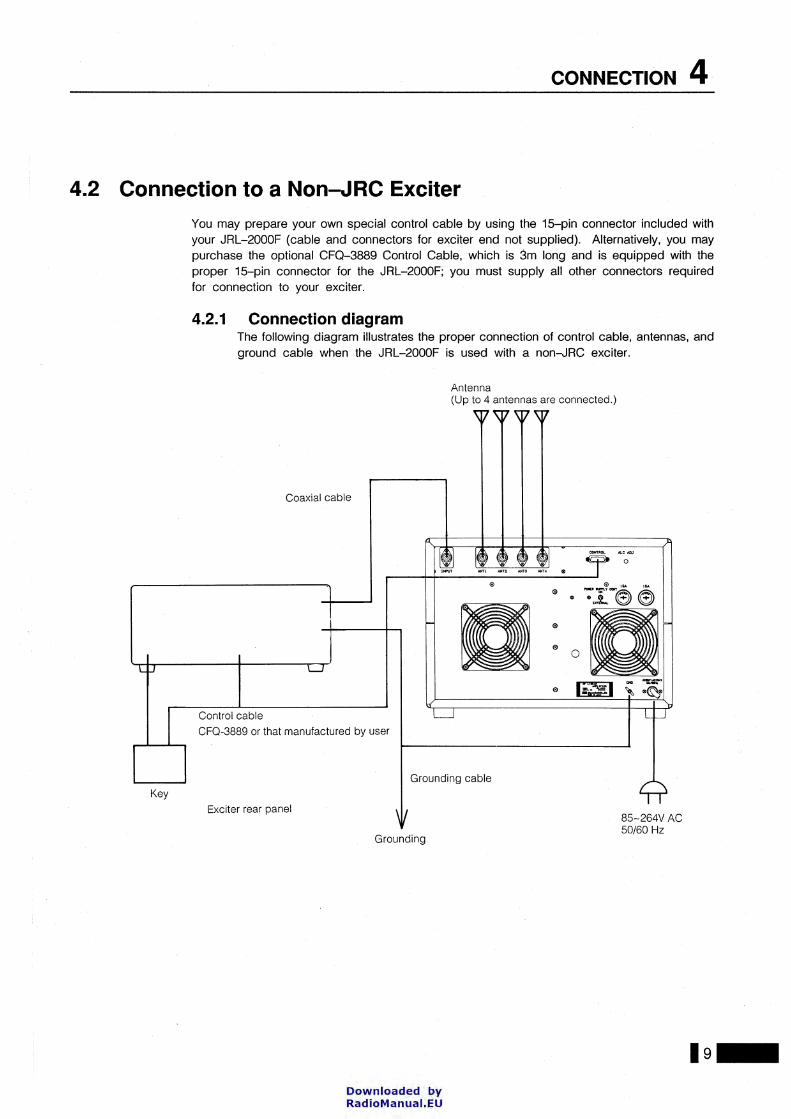
You may prepare your own special control cable by using the 15-pin connector included with your JRL-2000F (cable and connectors for exciter end not supplied). Alternatively, you may purchase the optional CFQ-3889 Control Cable, which is 3m long and is equipped with the proper 15-pin connector for the JRL-2000F; you must supply all other connectors required for connection to your exciter.
4.2.1 Connection diagram The following diagram illustrates the proper connection of control cable, antennas, and ground cable when the JRL-2000F is used with a non-JRC exciter.
Antenna (Up to 4 antennas are connected.)
\17\V'WW
Coaxial cable
Ir Ii i i il -~ ~'o~ ,,~ ~•~n~n~ns T
"""C:.I
@ I&A l&.o.
., ., * -:I-®®
a:oa --·
® li~l ~ *~*
Control cable L::J U--J CF0-3889 or that manufactured by user
Grounding cable
Exciter rear panel \II
Grounding
85-264V AC 50/60Hz
·9-Downloaded by RadioManuai.EU
] 4 CONNECTION
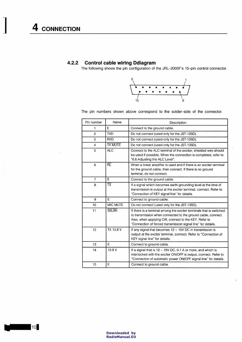
4.2.2 Control cable wiring Ddiagram The following shows the pin configuration of the JRL-2000F's 15-pin control connector.
8 1 ~ L \i • • • • • • 4 I f • • • • • ' I \
15 9
The pin numbers shown above correspond to the solder-side of the connector.
Pin number Name Oescription
1 E Connect to the ground cable.
2 TXO Oo not connect (used only for the JST-1350).
3 RXO Oo not connect (used only for the JST-1350).
4 TX MUTE Oo not connect ( used only for the JST -1350).
5 ALC Connect to the ALC terminal of the exciter; shielded wire should be used if possible. When the connection is completed. refer to "6.6 Adjusting the ALC Level".
6 RL When a linear amplifier is used and if there is an exciter terminal for the ground cable, then connect. lf there is no ground terminal, do not connect.
7 E Connect to the ground cable.
8 TX lf a signal which becomes earth-grounding Ievei at the time of Iransmission is outpul at the exciter terminal. connect. Refer to "Connection of KEY signalline" for details.
9 E Connect to ground cable.
10 MIC MUTE Oo not connect (used only for the JST-1350).
11 SELBK lf there is a terminal among the exciter terminals that is switched to Iransmission when connected to the ground cable. connect. Also, when applying CW, connect to the KEY. Refer to
"Connection of forced Iransmission signalline" for details.
12 TX 13.8 V lf any signal that becomes 12- 15V OC in Iransmission is outpul at the exciter terminal, connect. Refer to "Connection of KEY signal line" for details.
13 E Connect to ground cable.
14 13.8 V lf a signal !hat is 12- 15V OC, 0.1 A or more, and which is interlocked with the exciter ON/OFF is output, connect. Refer to "Connection of automatic power ON/OFF signalline" for details.
15 E Connect to ground cable.
Downloaded by RadioManuai.EU
JRL-2000F
ALC
RL
E TX
E
SELBK
TX13.8 V
E
13.8 V
E
CONNECTION 4
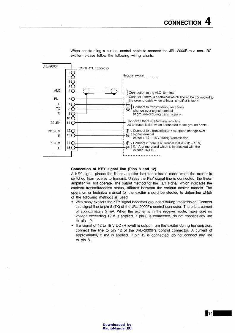
When constructing a custom control cable to connect the JRL-2000F to a non-JRC exciter, please follow the following wiring charts.
,---L- CONTROL connector
1Q Regular exciter
2Q .--------- .. --------- ... --3Q
. . . 4Q -· . 5
6
7 8
12.
13
~ J Connection to the ALC terminal : Connect if there is a terminal which should be connected to
).4--1----------..;.... the ground cable when a linear amplifier is used.
~ J Connect to Iransmission I reception ).4--1-----------w change-over signal terminal
(if grounded during transmission).
l-Jl------------+- Connect if there is a terminal which is set to Iransmission when connected to the ground cable.
EB J Connect to a Iransmission I reception change-over ).4-----------+-8 signalterminal
(when + 12 - 15 V during transmission).
14
15 EB J Connect if there is a terminal !hat is + 12 - 15 V,
115 011------------8 0.1 A or more and which is interlocked with the l___,=.....l : exciter ON/OFF.
Connection of KEY signal line (Pins 8 and 12) A KEY signal places the linear amplifier into Iransmission mode when the exciter is switched from receive to transmit Unless the KEY signal line is connected, the linear amplifier will not operate. The output method for the KEY signal, which indicates the exciters transmit/receive status, differes between the various exciter models. The operation or technical manual for the exciter should be studied to determine which of the following methods is used: • With many exciters the KEY signal becomes grounded during transmission. Connect
this signal line to pin 8 (TX) of the JRL-2000F's control connector. There is a current of approximately 5 mA. When 'the exciter is in the receive mode, make sure no voltage exceeding 12 V is applied. lf pin 8 is connected, do not connect any line to pin 12.
• lf a signal of 12 to 15 V DC (H Ievei) is output from the exciter during transmission, connect the line to pin 12 of the JRL-2000F's control connector. A current of approximately 5 mA is applied. lf pin 12 is connected, do not connect any line to pin 8.
111-Downloaded by RadioManuai.EU

] 4 CONNECTION
LOW: Iransmission
HIGH: reception
JRL-2000F Interna! Circuit diagram (CDJ-1143)
lmportant Note that automatic tuning will not be possible unless the KEY signal line from the exciter is connected.
Connection of forced Iransmission signal line (Pin 11) When this signal line is connected, the exciter will automatically enter the transmission mode when the JRL-2000F is performing its automatic tuning and SET operations.
Basic operation is not affected if pin 11 is not connected. However, smooth operation is possible by connecting this pin. The forced transmission signal is at grounded Ievei when the JRL-2000F issues a request for an RF signal. When there is no request, it is in the open state.
lf there is a terminal on the exciter that switches the exciter to transmit when grounded, connect that terminal to pin 11. lf not, connect pin 11 to the exciter's PTI terminal.
lf CW is used, connect pin 11 to the exciter's KEY line as weil unless negative voltage is applied to the KEY, for example in an exciter that uses vacuum tubes in the final stage. lf negative voltage is applied, do not connect pin 11.
Key input
e Exciter
Open connector outpul
JRL-2000F
Voltage resistance: 15 V Electric current: 50 mA maJ
CD1: This may be required depending on the exciter. Usually, connect directly. (General Purpose Diode; 181588, etc.)
Downloaded by RadioManuai.EU

Juter
max.
CONNECTION 4
lmportant Verify that negative voltage is not applied when connecting the forced transmission signal line to KEY. Never connect pin 11 when there is negative voltage applied. Take special care if using an exciter with vacuum tube finals.
Connection of automatic power supply ON/OFF signal line {Pin 14) The JRL -2000F power supply can be controlled by connecting 12-15 VDC (0.1 A max) to pin 14 of the JRL-2000F's control connector.
85-264 V AC : . • I I I
To the power supply unit
'-POWER SUPPL Y CONT. switch at the rear panel
113-Downloaded by RadioManuai.EU

] 5 OPERATING CONTROLS AND FUNCTIONS
5.1 Front Panel Controls METER 1: lndieates the outpul ~----1 power (Po) or antenna VSWR,
seleetable with METER switehes.
POWER switeh: Turns main power on and oft. When power is on, the LED is lit. When oft, the antenna switeh remains enabled, but antenna tuning and power amplifier operations are disabled. (See seetion 6.2)
PA switeh: Turns the DC power supply for the power amplilier on and oft. When the power amplilier is enabled, the LED is lit. II the LED is oft while the POWER switeh is lit, the antenna tuner and antenna switeh lunetions is operational, while the power amplilier is disabled. (See seetion 6.2)
liii 1 ~ !..JRCI
,-::
METER switches (5): Seleets the funetion of METER 1 (Po or VSWR) and METER 2 (lo, Vo or ALC).
SET switeh: Sets the operating parameters aeeording to data stored in memory to the eurrent exeiter frequeney. During SET Operation. the LED is lit. (See seetion 6.4)
REMOTE CONTROL SENSOR: ---1 Deteets infrared signal from NCH-
365 Remote Control Unit.
CENTAAL DISPLAY: ~ Displays frequeney band
in MHz, as weil as other messages.
METER 2: lndieates DC voltage (Vo), eurrent (lo) or ALC Ievei, seleetable with METER switehes.
r XMT indieator: Remains lit I II dunng transmJSSIOn.
1~1 la~. ~ lr--~--=--:~~.----.::1-, :1_J___----I---f1-:, __j JRL-2000F ~ II
MI' UNI.AA ~lii'IE" -
1-
1-
·-,.;;. ,...-:: 1"'"17171
TUNE switch: Automatieally tunes the antenna and sets other operating parameters and stores the matehing data to memory. The LED is lit during tuning. (See seetion 6.3)
ANTENNA switches: Sei"ects one of four antennas eonneeted to the JRL-2000F. The LED indieates the seleeted antenna.
-C]
MATCH indieator: lndieates the eondition of the matehing seetion. lf
'- the light is green, proper matehing is achieved; if orange, the matehing is poor.
'---
DRIVE indieator: lndicates eondition of drive signal from exeiter. II the light is green, drive Ievei is OK; if orange, the amplifier is being overdriven by the exciter.
Downloaded by RadioManuai.EU

OPERATING CONTROLS AND FUNCTIONS 5
5.2 Rear Panel Controls
INPUT connector: PL-259 type connector for input signal from exciter.
ANT1-ANT4 connectors: PL-259 connectors for outpul signal from JRL-2000F to antenna(s).
CONTROL connector: The interface control cable is connected between this connector and exciter.
ALCIADJ
ALC ADJ control: Used to adjust the ALC Ievei. (See section 6.6)
INPUT ANTI ANT2 ANT3 ANH *
EXHAUST FANS: For the PA unit and power supply unit.
® 0
*
®
®
®
POWER SUPPL Y CONT switch: When set to ON position, the JRL-2000F's power supply is controlled by the front panel POWER switch (and NCH-365 Renote Control Unit). When set to EXTERNAL position, the exciter can be used to control the power supply. (See section 4.2.2)
I&A
GND terminal: For connection to ground system
FUSE: 15A fuse for AC power line
115-Downloaded by RadioManuai.EU

] I 5 OPERATING CONTROLS AND FUNCTIONS
5.3 Remote Control Unit (NCH-365)
PowER switch: Turns main power on and oft. (See section 6.2)
PA switch: Turns the DC power supply for the power amplifier on and oft. (See section 6.2)
11-t-tl----1 TuNE switch: Automatically
SET switch: Sets the operating parameters according to data stored in memory to the current exciter frequency. (See section 6.4)
METER switches: Selects the function of meters 1 and 2 to indicate the outpul power (Po), antenna VSWR, DC valtage (lo) and current (Vo).
(..JRC) Remoie Controller
NCH-365
tunes the antenna and sets other operating parameters and stores the matehing data to memory. (See section 6.3)
ANTENNA switches: Selects one of four antennas connected to the JRL-2000F. (See section 6.2)
Downloaded by RadioManuai.EU
6 BASIC OPERATION
ln this chapter, the basic operation procedures of the JRL-2000F Linear Amplifier are described.
6.1 Preparation Before powering up your JRL-2000F for the first time, please verify each of the following items: • Check all antenna connections. • Check all connections to the exciter. • Check all ground connections. • Set the POWER SUPPLY CONT. SWitch On the rear panel tO EXTERNAL. • Turn oft the power switch of the exciter
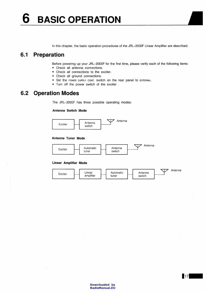
6.2 Operation Modes The JRL-2000F has three possible operating modes:
Antenna Switch Mode
Exciter Antenna switch
Antenna
Antenna
·17-Downloaded by RadioManuai.EU

] 6 BASIC OPERATION
6.2.1
lmportant The JRL-2000F has two distinct two operating states: OPERATING and STOPPED.
• OPERATING: This applies to any of the operating modes described above (Antenna Switch Mode, Antenna Tuner Mode or Linear Amplifier Mode). While in the OPERATING state, the JRL-2000F can also be controlled by the supplied Remote Control Unit (NCH-365). Upon entering the OPERATING state, the JRL-2000F automatically returns to the last set of Operating parameters that were used (antenna selection, tuner settings, etc.).
• STOPPED: When all power is cut oft from the JRL-2000F, it is considered to be in the STOPPED state. All functions are inoperable, and RF output from the exciter is not supplied to the antenna. Also, control via the supplied Remote Control Unit (NCH-365) is not possible.
Operation of the POWER SUPPL V CONT. switch The JRL-2000F power supply is controlled according to the setting of the POWER SUPPLY CONT. switch on the rear panel.
When it is set to EXTERNAL The power supply is controlled according to the state of the valtage applied to pin 14 of the 15-pin control connector. See section 4.2.2 for connection details. • When a valtage of 12-15 VDC is applied, the JRL-2000F is switched to the
OPERATING state (power ON). • lf no DC power is applied to pin 14, the JRL-2000F will be in the STOPPED state.
When it is set to ON The amplifier is continuously in the OPERATING state.
6.2.2 Antenna switch mode The JRL-2000F operates as an antenna switch when it is in the OPERATING state and the I POWER I switch is set to the OFF position. The selected antenna ( 1, 2, 3 or 4) is indicated by the LED on the ANTENNA switch buttons.
Even if the IPOWER I switch is set OFF, if the JRL-2000F is in the OPERATING state the unit can function as an antenna switch and operation can be performed with the Remote Control Unit (NCH-365)
Exciter
r----------, I Antenna I
~-4~ ~~--~ 1 switch 1 L--------.J
Antenna
JRL-2000F
Downloaded by RadioManuai.EU

BASIC OPERATION 6
6.2.3 Antenna tuner mode The JRL-2000F operates as an antenna tuner when it is in the OPERATING state, the I POWER I switch is set to the ON position and the lli9 switch is set to the OFF position. The two meters will be lit and their selected functions will be indicated by the LEDs on the METER switch buttons. The central display indicates the frequency band that the antenna tuner is currently tuned for.
Exciter
r----------, r----------, 1 1 I Antenna U Antenna ll--1f-----'
: tuner 1 1 switch • 1----------.J L---------.J
Antenna
JRL-2000F
lmportant • When changing the frequency band, when the frequency is not indicated, or
when the indicated frequency band is blinking, implement the automatic tuning or SET operation (see sections 6.3 and 6.4).
• During exciter transmission, be sure that the XMT LED is lit. lf it is not, the KEY signal is not properly connected. ln this case, please refer to section 4 and make sure all connections are correct.
119-Downloaded by RadioManuai.EU

6 BASIC OPERATION
6.2.4 Linear amplifer mode The JRL-2000F operates as a linear ampliter when it is in the OPERATING state, and both the I POWER I and lfßJ switches are set to the ON position. Du ring exciter transmission, the XMT LED is lit. Also, an idling current ot approximately 6A is supplied to the PA unit during transmission; during reception, the current is OA.
Exciter
r--------, r--------, r---------, I Linear H Antenna I I Antenna I 1 amplifier I 1 tuner n SWitch t-1 -+----' ~---------~ ~---------~ ~---------~
Antenna
lmportant • ln some countries, including the United States ot America, linear amplitier operation
above 24 MHz is not possible. • There is a time lag ot approximately 0.6 seconds between the time the PA LED
is lit and power is actually supplied to the power amplifier. • The JRL-2000F can not be put into the Linear Amplitier Mode it:
1. The operating trequency is not indicated in the central display; or, 2. The trequency band indicated in the central display is blinking. ln either case, implement the SET operation as described in section 6.4.
• The JRL-2000F can not be put into Linear Amplitier Mode while transmission is in progress.
Downloaded by RadioManuai.EU

BASIC OPERATION 6
6.3 Automatie Tuning Operation During Automatie Tuning operation, the JRL-2000F matches the currently selected antenna to the frequency of transmission. The matehing data and antenna selection is then stored into memory for instant recall at a later time.
There are two functions of the Automatie Tuner portion of the JRL-2000F: • VSWR Matehing - Matches the antenna VSWR and sets the__ Ioad in the final stage of the
exciter and linear amplifier to 50n. • Low Pass Filter (LPF) - The LPF attenuates undesired harmonics contained in the output
from the power amplifier.
After the tuning operation is completed, the data is stored in memory according to the JRL-2000F band assignments (see section 6.3.2). lt is necessary to perform the automatic tuning operation for each band or sub-band.
For example, the 14 MHz band is divided into four sub-bands. Therefore, automatic tuning must be done within each of these sub-bands in order to cover the entire 14 MHz band.
Since antenna selection data is also stored, tuning must be done after selecting an antenna.
Tuning data remain stored in memory until: • Automatie tuning within the same sub-band is performed again; or • The data is deleted from memory (see section 7.1).
lmportant Do not operate the JRL-2000F in any band or sub-band that has not been previously tuned. lf excessive VSWR is present, one or more of the built-in protection circuits may be activated.
121-Downloaded by RadioManuai.EU

I 6 BASIC OPERATION
6.3.1 Automatie tuning procedures The following instructions show how to implement the JRL-2000F's automatic tuning operation.
CD Set the exciter as follows: • Select CW or FSK mode. • Set desired frequency. • Adjust output power of the exciter to 30 - 80 W.
® Select the desired antenna to be matched with the antenna switch. Verify that the selected antenna is capable of operation in the band to be tuned, and that it is connected properly.
® Press the lruNEI button. The lruNEI LED will light and automatic tuning begins. lf the forced transmission signal line (pin 11) of the control terminal is connected to the exciter, the exciter will automatically enter transmission mode. lf pin 11 is not connected, see the "Supplements" section below.
The segment display rotates.
• Display during automatic tuning operation (segments rotating).
@ Upon completion of automatic tuning, the display will indicate as follows:
• Display indicating completion of automatic tuning operation
rr---ll Lb____4j
lf ~ is indicated or if the displayed frequency band is blinking, see the "Supplements" section below.
® The frequency band is now shown in the central display, and matehing data have been stored to memory for the current band or sub-band.
• Display indicating currently tuned frequency band (Example: 14 MHz)
® To verify that automatic tuning has been accomplished, set the [EJ switch to OFF and begin transmission with the exciter. Check that color of the MATCH LED is green. This indicates that the VSWR value is 1.5 or lower. lf the color is orange, see the "Supplements" section below.
Downloaded by RadioManuai.EU

~
lt lt
).
d is
le
Je
to ED ~e.
BASIC OPERATION 6
Supplements • When the forced Iransmission signal line is not connected:
Because the exciter will not automatically enter transmission mode, take the following steps to implement tuning: 1. Manually key the exciter to begin transmission. The JRL-2000F measures the operating
frequency. 2. Stop transmission from the exciter. 3. Transmit again and remain in transmission mode until the automatic tuning operation
is complete. Matehing data will be written into memory for the selected band or subband.
• When Po is indicated in the central display: This indicates that there is not sufficient input power to perform the automatic tuning operation. Adust the power output control of the exciter to increase the drive Ievei. The JRL-2000F can not perform automatic tuning unless there is more than approximately 20 W input.
• When A7 is indicated in the central display: This indicates that automatic tuning has not been completed successfully. Checkall antenna connections, antenna VSWR and exciter connections and try again.
• When the color of the MATCH LED is orange: This indicates that antenna matehing has not been completed successfully. Checkall antenna connections, antenna VSWR and exciter connections and try again.
This completes the automatic tuning procudure. The JRL-2000F can be used in any band that has been tuned by the above Operation. By implementing the automatic tuning operation in advance for all frequency bands and sub-bands that you plan to use, antenna switching and matehing data can be quickly recalled for instant QSY.
tmportant • ln some countries, including the United States of America, linear amplifier operation
above 24 MHz is not possible. However, the JRL-2000F can be used as an antenna tuner in any band.
• The VSWR value of the antenna itself is displayed on the VSWR meter on the front panel. This reading will not change even after tuning has been completed. lf the antenna VSWR is too high, it may cause radio interference.
• During automatic tuning the power amp is switched OFF even if the ~ switch is set ON. After tuning, the ~ switch will automatically return to its previous state.
• The antenna tuner is bypassed during receive operation.
123-Downloaded by RadioManuai.EU

] 6 OPERATION I (BASIC OPERATION)
6.3.2 JRL-2000F band assignment table The JRL-2000F stores preset matehing data in memory for each of the following bands and sub-bands:
Ham frequency Frequency The JRL-2000F memory band Antenna number
band (MHz band) (MHz) band assignment (MHz) 1 2 3 4
1.800-1.810 1.810-1.820 1 .820-1 .830 1.830-1.840 1.840-1.850 1.850-1.860 1.860-1.870 1.870-1.880 1.880-1.890
1.8 1.800-2.000 1.890-1.900 1.900-1.910 1.910-1.920 1.920-1.930 1.930-1.940 1.940-1.950 1.950-1.960 1.960-1.970 1.970-1.980 1.980-1.990 1.990-2.000 3.500-3.520 3.520-3.540 3.540-3.560 3.560-3.580 3.580-3.600 3.600-3.620 3.620-3.640 3.640-3.660 3.660-3.680 3.680-3.700 3. 700-3.720 3.720-3.740
3.5 3.500-4.000 3.740-3.760 3. 780-3.800 3.800-3.820 3.820-3.840 3.840-3.860 3.860-3.880 3.880-3.900 3.900-3.920 3.920-3.940 3.940-3.950 3.950-3.980 3.980-4.000 7.000-7.050 7.050-7.100 7.100-7.150
7 7.000-7.300 7.150-7.200 7.200-7.250 7.250-7.300
10 10.100-10.150 10.080-10.150 14.000-14.080
14 14.000-14.350 14.080-14.190 14.190-14.300 14.300-14.410
18 18.068-18.168 18.060-18.200 20.960-21.120
21 21.000-21.450 21.120-21.280 21.280-21.440 21.440-21.600
24 24.890-24.990 24.890-25.080 27.930-28.140 28.140-28.160 28.160-28.380 28.380-28.600
28 28.000-20.700 28.600-28.820 28.820-29.040 29.040-29.260 29.260-29.480 29.480-29.700
!
Downloaded by RadioManuai.EU

ls
BASIC OPERATION 6
6.4 SET Operation When one begins using the JRL-2000F or when the exciter frequency has been changed, the amplifier must be tuned by using the preset matehing data which are stored in memory. This is done by pressing the SET switch on the front panel.
When the SET operation is performed, the JRL-2000F automatically measures the transmit frequency of the exciter and instantly sets the antenna tuner and selects the proper antenna according to the the preset data for the operating frequency.
During SET operation, the JRL-2000F acts as a dummy Ioad so no interference is caused during tune-up.
lmmediately after turning the power on, the JRL-2000F automatically recalls the settings from the previous operating session. Therefore it is not required to perform the SET operation if you are to operate on the same frequency as before.
lf the Japan Radio Company JST-135 transceiver is used as the exciter, the SEToperation is not required. The JRL-2000F will read the operating frequency from the JST -135 and set the matehing data automatically.
6.4.1
lmportant lf the power amplifier is operated without performing the SET Operation and without matehing the antenna, one of the JRL-2000F's protection circuits may be activated or undesired waves may be emitted.
SET operation procedures After changing the transmitter frequency, press the I SET I switch. The LED on the I SET I switch will light and the preset matehing data will be read from memory. lf the forced transmission signal line (pin 11) of the JRL -2000F control terminal is connected to the exciter, the exciter will automatically enter transmission mode.
ln CW mode, the JRL-2000F samples the RF signal from the exciter and reads the matehing data from memory according to the transmit frequency of the exciter.
ln SSB mode, it is necessary to speak a few words into the microphone in order to modulate the signal and allow the JRL-2000F to sample the transmit frequency.
lf pin 11 is not connected, see the "Supplements" section below.
125-Downloaded by RadioManuai.EU

6 BASIC OPERATION
After performing the SET operation, the central display will indicate the frequency band that corresponds to the new settings. Always verify that the the exciter frequency matches the indicated band setting of the JRL-2000F, and that the proper antenna is selected. Also verify that the antenna VSWR matches the exciter's transmit frequency by turning the PA switch OFF and keying the exciter. The MATCH LED should light green, indicating a VSWR of 1.5:1 or lower. lf the MATCH LED is orange or red, see the "Supplements" section below.
Supplements • When the forced transmission signal line is not connected:
Because the exciter will not automatically enter transmission mode, manually key the exciter to begin transmission. lf the SSB mode is selected, speak a few words into the microphone. The JRL-2000F measures the operating frequency.
• When [fQ] is indicated in the central display: This indicates that there is not sufficient input power to perform the automatic tuning operation. Adust the power output control of the exciter to increase the drive Ievei. The JRL-2000F can not perform the SET operation unless there is more than approximately 30 W input.
• When the color of the MATCH LED is orange or red: This indicates an error in the stored preset data and proper antenna matehing has not been achieved. Piease refer to section 6.3 and implement the automatic tuning operation.
Downloaded by RadioManuai.EU

ld lS j_
lg lg s''
er e.
'n. )F
Jt.
lOt
m.
6.5
BASIC OPERATION 6
lmportant The preset data store the matehing data for a single seleeted antenna output (one of four). Therefore, if a different antenna is used or if the antenna feedline is ehanged to a different antenna input on the amplifier, it is neeessary to implement the automatie tuning operation onee again after erasing the previous antenna preset data (see seetion 7.1 ).
Switching Antennas
When the exeiter frequeney has been automatieally eounted during the SET operation, the antenna output (1,2.3 or 4) that is stored with the preset matehing data is seleeted. You ean also seleet any of the other antennas by the antenna switeh. The lit LED on the antenna switeh button indieates the eurrently seleeted antenna output.
...------- ANTENNA ---------,
CD = =
-----
= 3 2 4
Press the switch with the antenna number you wish to select.
127-Downloaded by RadioManuai.EU

6 BASIC OPERATION
6.6 Adjusting the ALC Level When the JRL-2000F is {)perating in the Linear Amplifier Mode (as described in section 6.2), always make sure that the ALC signal line is connected to the exciter's ALC terminal. The ALC Ievel of the JRL-2000F can be adjusted by following the steps.
CD Insert a regular screwdriver into the ALC ADJ adjustment hole on the rear panel of the JRL-2000F and turn the variable resistor fully clockwise (default factory setting).
ALC ADJ adjustment hole
I I ~~~~
~~ ~'~
~ 0
~· AMT~ ANT3 ~· ..
® ® ® -:I-~~ ..
a ® a~ ® 0
~ - --® ~ ·~ .
LJ LJ
® Connect a 50Q dummy Ioad or an antenna with low VSWR to the ANT1 connector.
® Set the exciter to the desired frequency and set the transmission mode to CW or RTTY.
@ Turn the JRL-2000F power supply on (with the IPOWERI switch on the front panel), select antenna number 1 (with the V\NTENNA I switch) and press the TUNE button. Refer to section 6.3 and implement the automatic tuning operation. The exciter's frequency band will be indicated in the amplifier's central display.
® Press the ~ and I ALC I buttons to change the meter functions accordingly.
ALC
III
-
Downloaded by RadioManuai.EU

~).
le
1e
IY.
ect ion be·
BASIC OPERATION 6
® Turn the exciter's power control to its lowest setting a.nd set the exciter to tl:le tra.nsmission mode.
(V Adjust the exciter's power control until the JRL-2000F's Po meter (left side) measures approximately 1050 watts. At this time, the pointer of the ALC meter (right side) should be a little beyond the white zone.
Po ID /VD
~
Meter indication
® Turn the variable resistor for ALC Ievei adjustment on the rear panel counterclockwise slowly, until the ALC meter's pointer is set inside the white zone. At this point, verify that the Po meter measures approximately 1000 watts.
ID/VD
0
Meter indication
/mportant Depending on the exciter you are using, it may not be possible to keep the optimum ALC setting within the white zone on the ALC meter. However, if the Po meter does not exceed 1000 watts, then consider the ALC adjustment properly set.
® Verify that the output power of the JRL-2000F does not exceed 1000 watts, even if the . exciter output power is increased.
@ Return the exciter to standby or reception mode. The ALC adjustment procedure is now complete.
129-Downloaded by RadioManuai.EU

6 BASIC OPERATION
6.7 Memory Backup
I
Two types of memory are utilized in the JRL-2000F: • Memory for preset data. • Memory for maintaining the JRL-2000F's operating states.
Memory for preset data The preset data written during automatic tuning operations are stored in EEPROM (ROM that can be electrically rewritten). The preset data are not erased when the JRL-2000F's power supply is turned oft and the amplifier enters the STOPPED state.
Memory for maintaining the JRL-2000F's operating states Data for maintaining the various operating states of the JRL-2000F (!POWER!,~. meter settings, antenna switch settings, frequency band settings, etc.) are stored in RAM, which is backed up by a battery.
The backup state of the memory changes depending upon the DIP switch settings described in section 7.5.
The backup period for the RAM is approximately two weeks if the battery is fully charged. During this period, the previous operating state is recovered whenever the JRL-2000F is turned on. lf the battery has been discharged, the contents of the RAM are lost and the some or all of the following default settings are recalled depending on the operating mode: • I POWER I : Off • Antenna switch: 1 • IE]: oft • Meter selection: [fQJ and [jQ] The above settings are the facory default settings. When the battery is discharged, it can be recharged by leaving the amplifier in the antenna switch mode or antenna tuner mode for about three hours or more.
Downloaded by RadioManuai.EU

at 3r
S,
!d
ld
d. 3d or
an de
BASIC OPERATION 6
6.8 Precautions The JRL-2000F is equipped with apower amplifier with low IMD characteristics and high linearity, and a power supply unit with a high power margin. The amplifier is designed to generate and output signals of high quality and stability.
However, failure to use the JRL-2000F correctly may result in reduced performance such as poor sound quality or radio interference. Therefore, special attention should be paid to the following points during transmission:
Frequency display Always verify that the frequency band indicated in the amplifier's central display matches the exciter's transmission frequency.
I MATCH I LED color Du ring transmission, the I MATCH I LED should be green in color. lf the color is orange or red, proper antenna matehing has not been achieved. ln this case, you must implement the automatic tuning operation as described in section 6.3.
I DRIVE I LED color Du ring transmission, the I DRIVE I LED should also be green in color. lf it is orange in SSB mode, it indicates that the APC (Automatie Power Control) circuit inside the JRL-2000F has been activated due to over-excitation.
Even when the ALC Ievei has been correctly adjusted, the amplifier's APC circuit may be activated if the power control or microphone gain on the exciter or the gain on the speech processor is too high. in this case, turn the power control or reduce mic gain until the DRIVE LED is lit green.
Meters The two meters should be checked regularly during transmission tö verify that the JRL-2000F is operating normally. • Check that the peak Po value is not over 1000 watts. • Check if the antenna VSWR is abnorr.nally high. • Check that the Vo voltage is set at about 80-85 V. • Check that the lo current is set at the correct value. When the continuous output power
is 1000 watts, the lo value should be approximately 22-27 A (input 1760-2160 W).
lf the meter values are different from their normal readings, one of the causes may be a change in antenna impedance. ln such cases, try matehing again with the automatic tuning operation.
131-Downloaded by RadioManuai.EU

SPECIAL OPERATIONS
This chapter describes special operations of the JRL-2000F, which are not normally used during everyday operation ..
7.1 Erasing Preset Data The preset data stored during automatic tuning operations can be erased from memory by following the following procedures
7.1.1 Erasing all data for a selected antenna All matehing data for a specified antenna switch setting can be erased from memory. in other words, if antenna 1 is selected to execute erasing, all preset data stored for antenna 1 are erased. Data for other antennas remain unchanged.
To perform this operation: CD Turn the I POWER) switch off.
® Press the switch for the antenna whose preset data you wish to erase (1, 2, 3 or 4).
® While holding down the selected antenna switch, press the )POWER) switch to turn the amplifier on. The antenna switch should be held down until the frequency indicated in the central display begins to blink.
7 .1.2 Erasing all data for a selected frequency band All matehing data for a specified antenna in a single sub- band can be erased from memory. in other words, if antenna 1 is selected to execute erasing and the JRL-2000F is currently tuned to the first sub-band for 20 meters (14.000 to 14.080 MHz), all preset data stored for antenna 1 and that sub-band are erased. Data for other antennas and sub-bands remain unchanged.
To perform this operation: CD Turn the )POWER) switch on.
® Press th Po meter switch.
® Press the switch of the antenna whose data you wish to erase ( 1, 2, 3 or 4 ).
@) Implement the I SET I operation at a frequency within the sub-band whose you wish to erase. Verify the frequency band indicated in the central display.
® While holding down the antenna switch, press the ~ switch. These two switches should be held down until the frequency band indicator in the central display begins to blink.
Downloaded by RadioManuai.EU

y
I.
d
3
·n
:y
m
~).
er
4).
sh
es inS
SPECIAL OPERATIONS 7
7.2 Write-protecti ng Preset Data
7.3
The preset data stored during automatic tuning operations can be protected against inadvertant erasure or changes by locking the lruNEI switch. This makes it impossible to implement the automatic tuning operation.
To perform this operation: G) Turn off the IPOWERI switch.
® While holdingdown the lruNEI switch, turn the IPowERI switch on. The lruNEI switch will now be locked
To undo this operation, simply repeat the above steps.
Using the JRL-2000F as a Dummy Load The JRL-2000F can be used as a dummy Ioad with an input resistance of 100 W. The operable frequency range is 1.8-30 MHz.
To activate the dummy Ioad setting: G) Turn the IPOWERI switch off.
® While holding down the ~ switch, turn on the IPOWERI switch. [EQI is blinked in the central display and the JRL-2000F functions as a dummy Ioad for the exciter until the IPOWERI switch is turned off. When turned on again, the JRL-2000F returns to normal operation.
133-Downloaded by RadioManuai.EU

I 7 SPECIAL OPERATIONS
7.4 Using More than 4 Antennas
I
The JRL-2000F ean be operated with up to than 4 antennas eonneeted direetly to the amplifier. However, by utilizing eommon, eommereially available antenna switehes, the JRL-2000F ean be used with stored matehing data for more than 4 antennas. For example, by using three antenna switehes, 8 antennas may be eonneeted to the JRL-2000F as shown below.
The 8 antennas eonneeted are: Antenna A: For the 1.9 MHz band. Antenna B: For the 3.5 MHz band. Antenna C: For the 7 MHz band. Antenna D: For the 10 MHz band. Antenna E: Multi-band antenna for the 14 and 21 MHz bands. Antenna F: For the 14 MHz band Antenna G: Multi-band antenna for the 21 and 28 MHz bands. Antenna H: Multi-band antenna for the 7, 21 and 28 MHz bands
A B C D E F G H (1.9) (3.5) (7) (10) (14/21) (14) (21/28) (7/21/28)
·- -------j-- ---: r·· ---------J---------1---: r·· -------j-- --.. o---J .. I I I I
S1 : : S2 i : S3
ABT 1
-------------- -------------·
ANT 2
JRL-2000F
ANT 3
S1 - S3: Antenna ehange-over switehes (50 n type)
Memory address of preset data
ANT 4
When the antennas are eonneeted as shown above, the matehing data are stored as follows:
Frequeney Antenna band 1 2 3 4
1.9 A
3.5 B
7 c H
10 D
14 E F
21 E G H
28 G H
A - H indieates memory bloeks in whieh matehing data are stored for respeetive antennas.
Downloaded by RadioManuai.EU

n e
s:
).
7.5
SPECIAL OPERATIONS 7
Setting the DIP Switches
The JRL-2000F has DIP switches for setting the memory backup state and fro setting the overdrive alarm settings. These DIP switches are located on the CDJ-1143 CONTROL printed circuit board at the upper section of the main unit. lt is visible when you remove the top cover of the JRL-2000F.
The functions of the DIP switches are described in the following table:
Switch number State Function
ON Sets the RAM back-up state according to the states of DIP switches 2 and 3.
OFF Regardless of the states of DIP switches 2 and 3, the ollowing functions are intitialized when the device is shut down (the 13.8 V power from the
1 exciter is turned off or the power cord is unplugged from the outlet).
· Frequency setting . I POWER I ON/OFF · States of the meters · The selected antenna
· §:]ON/OFF
ON Backs-up the frequency setting when DIP switch 1 is set to ON. 2
OFF Does not back-up the frequency setting.
ON Backs up the ON/OFF states of the I POWER I and §) when DIP switch 1 is
3 setto ON.
OFF Does not back up the ON/OFF states of the I POWER I and §). ON Does not output the over-drive alarm when the ~ is OFF
4 (supports a 200 W output).
OFF Outputs the over-drive alarm when the ~ is OFF.
Factory DIP switch settings are shown below
ON ON ON ON
2 3 4
ON ON ON OFF
135-Downloaded by RadioManuai.EU

8· PROTECTION FUNCTIONS
8.1 Cooling Fans
The JRL-2000F is equipped with two cooling fans,. which are activated under the following conditions:
The cooling fan in the power amplifier This fan activates when the PA heat sink temperature exceeds approximately so·c. and turns off after the teperature drops below approximately 4o·c.
The cooling fan in the power supply unit This fan activates when the power supply heat sink temperature exceeds approximately 45·c. and turns off after the teperature drops below approximately 4o·c.
8.2 Causes of Alarmsand Corrective Measures The JRL-2000F is equipped with alarm circuits so that all internal electronic circuits can be protected from stresses and overloads caused by overdrive and abnormal output Ioads. lf an alarm occurs, verify the cause and take the appropriate actions as described below.
When an alarm is activated, the alarm number is shown on the central display of the JRL-2000F. lf the alarm number is lit steadily, the alarm state is currently in effect. lf it is blinking, the alarm condition has occured but is no Ionger in effect.
All alarms can be cancelled by turning the )POWER) switch off and on again.
Downloaded by RadioManuai.EU

g
s
' ,,
e lf
.-
J,
Alarm Iist
Display
A1
.
A2
A3
A4
A5
A6
A?
A8
A9
L.
Meaning
Abnormality in power supply unit
Abnormality in power supply unit
Overheated power amplifier
Unbalanced power amplifier
Over -excitation
Excessive tuning power
Abnormal automatic tuning
Abnormality in the antenna
Abnormal power amplifier Ioad
L ...
PROTECTION FUNCTIONS 8
Cause and operational lnspection and corrective condition measures
The outpul voltage from the Check the power supply line power supply unit has (110 or 220V AC). dropped while the §;] is Also. verify that the outpul is not on. The cause is usually a excessive. sudden drop in the AC line voltage.
Over-current (30 A or more) lf the power amplifier current is excessive, or over-heating (80°C or decrease the exciter power. more) in the power supply
unit.
Excessive voltage in the AC Check the voltage in the power supply input line (270 Vor more) line.
Check the ventilation.
The power amplifier unit has Verify that the outpul is not excessive, that been over heated. the air filter is not clogged and that air is (80°C or more) flowing normally.
Output balance for the 4 lf the fuse in the power amplifier section is power amplifier circuits is blown, replace it with a new one. uneven. Verify that the idling current is
approximately 6 A.
The excitation power from Reduce the power from the exciter. the exciter is excessive. l
(approximately 130 W)
The power from the exciter Reduce the power from the exciter is excessive during the Correct power is 30 - 80 W. automatic tuning operation. (80 W or more)
Matehing with the antenna Check the antenna connection and the has not been achieved VSWR value. during the automatic tuning operation.
The antenna VSWR is too Verify that the correct antenna is selected high. for the operating frequency, and that it is
properly connected.
The Ioad seen from the Verify that the automatic antenna tuning power amplifier is abnormal. operation has been correctly implemented
and if necessary, perform the automatic tuning operation again. Also, verify the following : · That the antenna is normal. · That there is no abnormal outpul from the
exciter (the linear amplifier outpul deviates resulting in oscillation).
---·- -------·--·-L__
137-Downloaded by RadioManuai.EU

9
9.1
PRECAUTIONS ON MAINTENANCE AND OPERATION
Cleaning the Main Unit
The JRL-2000F has two internal ventilation fans. They draw in air from the front panel and expel it through the rear panel. An air filter is mounted on the intake vent at the front panel so that dirt or dust will not enter the main unit. Examine the condition of air filter behind the intake vent of the front panel and occasionally clean the air filter. At the same time, clean the louvered area of the intake escutcheon, and the guard and propellers of the ventilation fans to remove any dust and dirt. Close attention should be paid to the air filter because if it becomes clogged, the internal cooling performance declines, which may result in an alarm or machine failure.
The air filter should be removed in the following manner: CD Turn off the power supply to the JRL-2000F and unplug the power cord from the outlet.
® Remove the screws from the intake vent and pull out the air filter.
D lüj
Downloaded by RadioManuai.EU

---PRECAUTIONS ON MAINTENANCE AND OPERATION 9
9.2 Maintenance of the lnternal Circuits
1d lt is not required to perform adjustment on the JRL-2000F internal circuits as they are completely preadjusted at the factory.
:er lf, however, any problems occur during normal handling and operation, contact your dealer or your local JRC representative.
Jly
lrs
1al
et. 9.3
Attention JRC is not held responsible for any problems arising from intentional readjustment or modification of the internal circuits by the user.
Radio lnterference Precautions Ham radio transmitters may, under certain circumstances, cause interference to domestic television sets, radios, stereos etc. Of course, such problems are usually not entirely attributable to the ham radio station. JRC, as a manufacturer, conducts very thorough adjustment and inspection in an attempt to prevent undesired or spurious radiation. lf, however, radio interference does occur during operation, stop transmitting immediately. Special care should be taken in regard to the following and appropriate measures should be taken. • lf it has been ascertained that a ham station is causing interference to television and radio
reception by its radio waves, you should stop transmitting immediately to verify the presence or absence of interference and the degree of interference.
• lf it has been ascertained that the interference has been caused by your ham station, inspect the transmitter and antenna system and take appropriate measures according to the degree of interference.
9.4 Precautions Against Power Surge Caused by Lightning
When there is electrical storm activity in the area, lightening surge pulse may be induced in the antenna. in such a case, the radio may be struck by a surge of very high voltage. in order to minimize darnage by lightning cciming in via the antenna, the JRL-2000F is equipped with a high-speed arrestor. Nevertheless, relays in the output circuit, tuner circuit, the finalstage amplifier etc, may be damaged due to their highly precise and delicate circuit configurations. Therefore, the user is advised to stop operation immediately and turn off the power supply when an electrical storm threatens.
139-Downloaded by RadioManuai.EU

10 PROBLEM SOLVING
1 0.1 After-sales Service
When the JRL-2000F does not oparate properly, refer to "10.2 Troubleshooting" to make sure that it really has a problem. lf it should become obvious that the JRL-2000F does have a problem, immediately unplug the power supply cord from the outlet and contact your dealer or the JRC Customer Service Department. See the back page of the warranty for regulations on warranty coverage.
1 0.2 Troubleshooting
Before you jump to the conclusion that the machine has a problem, check the following items.
Symptom Cause eure Reference
No power-up 6.2.1
(j) The antenna switch The 13.8 V power from the exciter Check the connections or setthe POWER (P. 18)
cannot be operated is not supplied or the POWER SUPPLY CONT. switch on the rear panelto
independently. SUPPLY CONT. switch on the rear ON.
® The POWER cannot panel is setto EXTERNAL. Turn the POWER on alter setting the exciter
be turned on from The exciter is in the Iransmission in the reception mode.
the. front panel. mode.
The ~ cannot be (j) Automatie tuning has not been Implement the automatic tuning operation. 6.3
turned on. achieved (the frequency Or switch to the antenna in which the (P. 21)
display is off or blinking). automatic tuning operation has been
successfully achieved.
® The exciter frequency is not Resetthe exciter frequency within the Harn
within the hamfrequency frequency band.
band. The ~ cannot be turned on in the 28 MHz
® The frequency is in the 28 frequency band.
MHz frequency band. Turn the ~ on alter setting the exciter to
@ The exciter is in the reception mode.
Iransmission mode.
The automatic tuning (j) lnsufficient outpul power from lncrease the outpul power from the exciter. 6.3
operation and I or the theexciter (P. 21)
SET operation cannot ® The control cable is Connectthe control cable securely. 4. be implemented. disconnected.
® The coaxial cable is not Make correct connection.
connected correctly, or the
cable has poor contact.
Low outpul power (j) The ALC Ievei setting is not Readjust the ALC Ievei. 6.6
correct. (P. 28)
® The outpul power from the lncrease the outpul power from the exciter.
exciter is insufficient.
® An alarm is in effect. Turn the POWER on again alter turning the 6.2.4
JRL-2000F off. (P. 20)
@ The~isoff. Turn the ~ on.
The frequency does not The exciter is in the split mode. During the SET operation, the exciter 6.4
change correclly dur- Iransmission frequency is counted. (P. 25)
ing the SET operation.
The automatic tuning CD The outpul power from the lncrease the outpul power from the exciter. 6.3
operation is aborted exciter is insufficient. (P. 21)
while in progress. ® Relay is not switched in the ln the automatic tuning operation, the
Iransmission mode. frequency is counted first, and then tuning
is implemented. When the operation shifts
from frequency counting to tuning, set the
exciter to the reception mode first.
When entering the The battery that backs up the Charge the battery for a minimum of three 6.7
operating state upon RAM has been discharged. hours. (P. 30)
start-up, there is
nothing displayed on
the central indicator.
Downloaded by RadioManuai.EU

Jre
ug ice
ns.
ce
I)
~)
~
))
1)
11 OPTIONS
ln order to use the JRL-2000F most effectively, the following control cables are available:
Control cable for the JST-1350 (CFQ-3890) This is a cable exclusively used for connecting the JRL-2000F and the JST-1350. lt is 3 m lang and has a connector at each end.
~'"""~ 1 \~ 3m
General-purpose control cable (CFQ-3889) This is a control cable for a regular exciter and is 3 m lang. lt has a connector for the JRL-2000F at one end and the other end is free to accept a suitable connector for the exciter you are using.
~l ~ 3m
Pin number Color of Wire Name
1 Shield Wire E
2 Brown TXO
3 Blue RXO
4 Gray TX MUTE
5 White ALC
6 Red RL
7 Orange E
8 Yellow TX
9 Shield Wire E
10 Green MIC MUTE
11 Black SELBK
12 Bright Green TX13.8V
13 Pink E
14 Sky Blue 13.8V
15 Shield Wire E
@ This must be always connected. * Either end must be connected.
Oescription I
@ I
X
X
X
@
6
6
* @
X
6
* 6
6 @
6 Connection may be required, or connection may be convenient. X Exclusively for JST-1350. Usually, connection is not required.
141-Downloaded by RadioManuai.EU

12 ATTACHED DIAGRAMS
12.1 Externat View
12.2 Block Diagram
12.3 Connection Diagrams
I
JRL-2000F NAH-232 CCB-367 CAH-377 CFF-361 NBL-169 CBG-68 CBB-13 CFR-102 CFG-111 CSC-433 CDJ-1143 CML-334 CS0-387 CSA-222
Overall connection diagram Power amplifier unit connection diagram Power amplifier control connection diagram Power amplifier connection diagram Power combiner connection diagram Power supply unit connection diagram Main power supply connection diagram Power factor corrector connection diagram Noise filter connection diagram Matehing circuit connection diagram Antenna switch connection diagram Control connection diagram Display connection diagram Switch panel connection diagram Relay circuit connection diagram
Downloaded by RadioManuai.EU

_e::]_ II K
)0
.. ~ .. ~ 1~-.:1 0
""' A1'$Q'I-..,..
~D 0 0
a 0
. .
~~-I.: .. 0 'r!ll '1'!11
® ®
.. ·~ '~ ·~ '""'
I 0 ~
lt tt~ ""'~ """"" C( ~
18UBd JB8tJ
<O•
II r-1
~ ~
[ ~ ~
[ m~~~m~~~~~~~m~~mm~~~~
,., ~
I I II
'"' I~ I~ I~ I~ I -c m 01=1~1~1=1~1GJ [Z] 0 -c 0
I I ---· .
§E] -·~·-.~ ..
I~ I .111000z;-,111r
-=llml e!B
i8UBd lUOJ.::J
Downloaded by RadioManuai.EU

-
I "
-r
EfW
:_ ~w
1 I
I
I~
INP
UT
FAN
VD
D
PA
CO
NT
RO
L
---,
I I _
_j
POW
ER
,
~o-------lFACTOR
1350
VD
CI
I C
OR
RE
CT
OR
"'
SW
RE
G
12
V
MA
IN
SW
RE
G
IMP
D
ET
MA
TC
HIN
G
CIR
CU
IT
il
: il
RE
LA
YS
CO
NT
RO
L
UN
IT
DIS
PL
AY
U
NIT
POW
ER
D
ET
L..L
__
_ .
J
AN
Ti
AN
T2
AN
T3
AN
T4
AL
C6
L
----
----
----
----
----
----
----
----
--{
)KE
Y&
PT
T
SW
ITC
H
PA
NE
L
I
L _
_
'---_
----
' P
o.
VSW
R
VD
. ID
. A
LC
_
_ _j
I
RE
MO
TE
L
_I
CO
NT
RO
LL
ER
___.
N
I N
(_
JJ
~
N
0
rn8
1-n
O
I
0-n
7
'r
o
-z
)>
m
{j)
)>
JJJJ
)>
)>
::S
:s
"U
r -n
m
JJ
Downloaded by RadioManuai.EU

I !
-.f:>. I
CS
D-3
87
S
WIT
CH
P
AN
EL
D --p,.
""
o•c-
"'• "'"
:~, .J
11
2
RE
MO
TE
C
ON
TR
OL
LE
R
0 w
g
NC
H-3
65
I r-
---1~;;~~-lt:;;~~------------------------~P~4~1~0~~-1~;;~t---~
EXCIT
ERW
I I.J
3 W9
85-264V~
AC
11
Zl --{Pi~
L
CD
..J-1
14
3
CO
NT
RO
L
P4
01
P3
.J
3
CS
A-2
22
R
EL
AY
C
KT
W1
W4
05
w
t'"U
"fe
)w3
o3
I P
3D
2fe
)w3
D2
.J3
01
CS
C-4
33
A
NT
EN
NA
S
WIT
CH
~,-----fi
CF
G-1
11
M
AT
CH
ING
TB
3
TB
4
TB
1 T
B2
NA
H-2
32
PO
WER
A
MP
LIF
IER
r ~ IN
PU
T
AN
TE
NN
A1
AN
TE
NN
A2
AN
TE
NN
A3
AN
TE
NN
A4
.......
1\)
I (;)
c_
-:r
J
Zr
-;,
ml\
) :r
JO
()0
0~
ZI
z-"
m
r
()_
-;z
o
m
z)>
:r
J 0
)>
)>~
G)-
u
:rJr
)>
-"
~m
:rJ
Downloaded by RadioManuai.EU

+:>.
0) -
~.~
P2
5
J2
01
P2
1
CC
B-3
67
[" PA
CO
NT
RO
L
P2
2
P2
3
P2
4
~ ~
P2
B
W24
-=
<::
> B
1
W4
1-W
44
1
.5D
-2V
(Z
CE
D3
10
) W
23
1-W
23
4
2.5
0-2
V
(ZC
ED
31
1)
W3
07
5
D-2
V
I I I I I
W23
(Z
CE
01
10
14
)
W2
(ZC
ED
11
01
3)
I rs
cl
P2
13
0 0
J3
T
B1
T
B2
P
2.
~J1
J4
•
CA
H-3
77
~
POW
ER
A
MP
LIF
IER
N
O.
1 J5
•
W41
P
21
2
t\J2
W4
2f
W43
t W
44
P2
13
~J1
;:-'
J4
•
CA
H-3
77
0
POW
ER
A
MP
LIF
IER
P2
14
f.
~J2
N0
.2
J5
•
I J3
T
B1
T
B2
0 0
I {5
C)
P2
23
"""
t"'7,..~n.o
.on
4':
1.\
P2
3:
BC
P
20
4
(
W2
31
I
J2
04
P
23
2
IN-1
I C
FF
-36
1
W2
32
IN
-2 PO
WE
R
CO
MB
INE
R
W2
33
I
OU
T-
~~
P23~-
I : ::::
""'' ~
~
P2
34
W3
07
r.
.
_..
I\)
1 w z )>
I I I\) w
I\) -u
0 :2:
m
JJ
)>
~
-u
r Tl m
JJ
Downloaded by RadioManuai.EU
E:::
--
-+:>.
-....!
I
NO
. 1
PA
-"
" -
" Ll1 ~ m
5
Fl6
4
47
0
~1
~~5~
I 2
-3
+
6-
s+
1
3-1
2+
_
10
+ I
2 2
2 2
AV11~ AV12~ RV13~ RV14~
2k
iTID
2k~
2k
~
2k
~
[ijj
MJ
-
TF
I1
05
08
~~-
C2
3
0.
1.u
P2
6
UJ 1 9
N0
.2
PA
-"
u; u;
<
<
H
H
m
m
2 3 0
o; " "
Ll1
Ll1
<
<
H
H
m
m
4 5
0
TF
I2
05
08
~~-
C2
5
0 .!
.u
r-----. R
74
1
00
14
IC
2
3/4
Fl3
2
2.2
k
1~
Fl3
1
2.2
k
11
< ..
I " < .. " I <
.. " I "' < ..
P2
1
P2
2
P2
3 P
24
~~~~
nrr
I
~1
~ L
~ED359
l:ä<W
J
IC2
2i-t
4~x
ITE
MP1
1 T
P1
c1iT
O
.!JJI A
72
10
k
~----------~~~~ I
NP
UT
Fl7
0
10
k
Fl1
C3
1 ~~ ~ 1
0k
t11
"1
o .
ti"lo
.ti"
?+ ~
C7
;·I f"1
f
Fl3
5
33
k
Fl4
0
2.2
k
~IC
3 1
/4
+
0
Fl3
9
2.2
k ~
3 /4
+
5
FIS
10
k
CD
1
~
7 IC
1
4/4
FIS
47
0
~CD~~~B IC
1 1
/4
~ -
+
9 1
0
Fl7
3
22
0
Fl4
5
33
k
IC1
""IC
S
NJM
29
02
CD
1'"
'CD
11
1
SS
18
1
~~gk
~~:~
k F
l34
4
.7K
C4
4
. ?1
1
,!;
"+
CD
9
Fl2
0
10
0k
Cl 1
Fl2
7
2jS
CD
11
4
.7k
Fl2
8
2.2
k
~ C14 0.
111
7
rP
.IC
2
2/4
;);
6-
C1
5
0.
111
Fl2
2
2.2
K
lo--
Fl2
5
15
k
.mF
I2
4
Ili'k
Fl2
6
15
k
I I I
• T
R4
C
24
R
B
2S
C2
87
3Y
0
•0
1JJ
R2
C
B
Li
10
0.u
15
0k
0.
1u
5
.1k
C3
5r
L2
L
3
111
')io
o.
L1
:00
" n
10
Lo
-:.
p:J
Yci,
. L
5ß
: +
:JP~1"
t
~ 1 I
10
01
1
1 L
S
1 10~
~ 1
00
u
C4
2
fi1
u
i;l;
L1
2
10
0 u
J2
r2
; [1
6
0-6
6
6 6
6 6
6 6
6 6
6 c
.J2
~:
1~~:
~ t
C4
3
a··
j!~b
1
00
.u
f 6
6 6
6 6
6
I
C5
2
n!u
;);
4 3
2 1
. 5
7 1
4
15
8
13
1
2
10
1
6
6 9
11
3
2 4
5 1
, 6
7 8
I ~PCED903
> "'
> "
>
UJ
'\'
~ U
J >
H a: a a: \:;' 0
u.
>
~ !
~ ... "
> "'
~ 1:
... >
+
UJ
J.
. ;:
>
z ""
" L
..J
>
" <
...
-u.
<
<
<
+
UJ
..
.. J:
.......
1\)
I (A
)
0 0 rn
I (A)
0)
-....,J
"lJ
)>
0 0 z -I
JJ
0 r
Downloaded by RadioManuai.EU

a: w
u._ _
.J 0... ~
<(
a: w
$: 0 0... r-.... r-.... C
l) I
I <(
0 Cl) I
C\l
,...-
[Bi w
o
a
1re2 ~Bi
Eh
~
I I
~4!-=~"---'H~PWC~TR12 ~5
R1
5
i~~W T
R1
5
~ I i
INP
UT
(i)
C:8, 0
0}
I T
i L
.HE
03
49
I
i ~
4
1 T
R6
i 6
8
2W
r
fl C
5
R1
R
2
R6
2
47
0p
6
8
68
2W
2
Wx
2p
ara
. C
9 r-fH
Q
.47
JJ
7fr-
I
~~ ,1,
L __
3 2
"' "' "' <
<
... ... m
m
TR
13
2S
K4
0B
X3
I I T
3
: L
HE
D3
51
I (1
) (2
) I
D !O
UT
PU
T
OU
TP
UT
. I [
-:~:
I iK
40
9t I ~:.T
m ~:
C1
4I
C1
5I
C1
'i I ,_}TI5~ %
0.33~x3pare.
*LH~0524
LH
JD
52
4
~R21
TR
21
h-®
4
i/2W
T
R2
4
--,~
2S
K4
08
X3
4--fF
-.J 6. B
ux
2s
er 1
es
C
22
C
23
i ..
l.h!=74
~-,.,o. 1u
4 5
" .. "' "' <
<
... ... m
m
3
2S
K4
09
x3
~s
~iOK
~A~~
TR
31
-2-\--.J
\AA
,-.-E3
-t-+--4
"'-'"
"'f-'-'4
~~tTl
2S
K4
09
x3
2
SK
40
8x
3
2SI(4-Cf9X
3 2
SK
40
8x
3 ~
C4
2
C4
3
6.8
.ux
2a
er1
es
I I
r
~~
~ ~ '
R6
4
RB
R
5
C7
6
8
2W
68
4
70
p
2W
x2
pa
re 1-t
CiO
· n
,o.4
7.u
R
47
-50
1
5
T4
1
2W
x4
pa
ra.
LH
ED
350
r
1 '
"2
HtliN
PU
T (2
)
I
PC
ED
0
09
i2
.________j
Downloaded by RadioManuai.EU

,-----~·
TO
P
A
NO
. 1
1 1~
~:S
f T
T
5
~~~.
~~~
~ :
::::~u
-c::v
.....1
.
1o
w<
' :
I L
HE
D3
64
1
1\J
I I
T3
----
1 W
LH
ED
r9
2R
-1
-E
I
()
R3~
35
9
I :;R
1
00
L
4
W
10
W
10
0.U
H
0)
....... -o
CD
3
()
~ ~
IH/
l ~
'" J,
! f1
1S
15
85
::;E
T
O
PA
N
O.
2 1
I 1~~
: m
:
u-1
3
es
c1
o
10
W
47
px3
pa
ra.
TO
. 0
••
I •. 0 '" r
~ ()
IN-4
I
"'.
-<: 1
00
.u
---
L_
I
I s::
O
J z ~-
J"
l I
T····
·1
T~~.
..
I I
I ~
1 4
5 2
; 1:--
s a
~ -
+
+1
2V
K
4
E
Vf
Vr
~
--1:>- 1
Downloaded by RadioManuai.EU

-
B5
.-2
64
V
AC
[
03
1\ll
50
/60
Hz
04
w
)~T
PS
1
sw
RE
GU
LA
TO
R
61
CF
R-1
02
N
OIS
E
FIL
TE
R
CB
B-1
3
I I
CB
G-6
8
POW
ER
~~o
v~ I
I ]~~
ov M
AIN
P
S
VPA[
c; I
F A
C T
OR
O
UT
l
IN
OU
T
CORRECTO~
I ~ 30]
oc OU
TP
UT
3
0A
m
ax
____.
1\)
I w z O
J r;- ___.
(})
<D
-o
0 ~
m
:0
(/) c -o
-o
r -<
c z -l
Downloaded by RadioManuai.EU

111111
111111
()
1
-L
I
35
0V
D
C
INP
UT
C0
21
1
]TE
20
8
TR
20
1
TR
20
3
"~------0=~~~~~~~~~~--~----~----~------------------~------~.-~~-()+
D
TF
<;;
>:O
S
C2
0 1
-3
0
.01
JJ
5o
ov
C2
01
-2
47
0ll
t
45
0V
J:I+
C2
01
-:1
4
70
.u
45
0V
s I~HI
~: I
I 1
C2
03
I
3.3
.U
TE
20
2
I 4
00
V
~ T
P2
01
rE209
I I 1 C
24
0
Iu
~TR206
' 1
/
C2
34
0
.:1J
J
R2
56
1
.51
<
C2
11
rr-
0.1
11
;J;
I
TR
20
8
!tii ~
lt
Vcc
IC2
01
~ , " ... nJ
3
.3K
I
QT
I
hR
22
B
,-r r
s 13 R
22
9
I~;i~2
U 8
20
1<
>
I R
23
0
51
K
C2
13
1
00
0p
TA
20
1-2
04
2
SK
12
50
IC
20
1
TL
59
4C
N
C0
21
1,
21
2
RG
4C
TA
20
5,
20
6
IRF
U1
20
IC
20
2
OP
O
?D
P
CD
21
3.
21
4.
21
6
HZ
5C
1
TR
21
1
I 2
SC
26
55
II
CD
20
3-2
10
. 2
15
. 2
17
. 2
16
I
1S
H:i
BB
--:r
;J;
C
23
3
0.1u~ ~
:~~
~
TA
21
2
R2
36
1
5K
R2
50
8
.21
<
R2
53
S
.Bk
CD
21
0
R2
34
lO
K
R2
35
~ R
23
3
21< 1
10
k
~·~~~~
C2
08
-2
gog~
JJ *
C2
0B
-1 I
0 .1
.u
20
0V
TE
20
7 I
C222~
0.1
11
:;J;
C2
2.;
-=r
O .
1u
;J;
9 B
6 7
~-
~~~
~ C:l
7
R2
57
R
25
4f I
4.7
1<
6
.81
<
TR
21
0
:::J\
, ..
..
C2
25
---:
I:'"
""
0 .1
11
;J;:
I C22
6~ 1° 5
~,..
_ ~ 2
20
JJ
R2
55
lO
K
C2
35
~
C2
36
r1
0 .1
11 * t
3 1
00
JJ
7 -,t
, IC
20
3
IC2
02
112
~·
C
23
7
'" ;J;
PC
ED
90
0C
0 .i
u 7
tr
C2
27
~
Iu
;J;
C22
B--
-:I:
'"""
0
.1JJ
;J;
:
4 2 3
rtl
oc
OU
TP
UT
.J5
06
1 E
PA
1
00
V/5
V
IPA
5
0A
/5V
VP
A
ON
R
ES
P
FA
N
VP
A
ON
C
ON
T
K1
O
N
+1
2V
-12
V
E
-L
1\.
) I w
0 OJ GJ
I (j)
CX
>
~
)>
z -o
(/) c z -l
Downloaded by RadioManuai.EU

I (J1 1\)
-r--
AC
IN
PU
T L- I I
I I
R3
11 _
__
_ 1
10k!...~J
20W
R2
C
14
2
4
10
00
p
10
W
50
0V
~~~~~~~~~~+
lf
35
0V
D
C
OU
TP
UT
11===~~~~1JJ!W~~-
·~~~--
~ I
I I
I I
I I
'-'
1 '."'
':'~
I -
-2
N!T
-~R29
·.,-~~
1
. ·
-·
r.n.::~.
I
es::
0
.47
JJ
25
0V
~Vref
6 1
21
1
1.
15
O
UT
G
ND
IC1
I ~
" i CD
[''
I 0
'"I
C6
4
I '"
I I
'---<
R2
3
16
5
R2
4
5.6
k
R2
7
6.2
k
L---~--------~~~~~~~~==~~;;,;::=~======~~====~==~~---*~~+-----~~P~T~H~9M04BF222TS2F333
I
C1
6
0.
iu
+1
2Y
L1
2
72
u
L1
1
??_1
!..
l.
TC
51
7lr
1u
~C62
I"'~ 1
00
u
C6
1
10
0JJ
J 6 ~T12V
C6
6
b0
.1JJ
~1,2I+12V
C6
7
J;o .1
.u
--r-::-:
:-::-to
8
I p s
A
LM
C6
8
Io .l.
u
~4,5I+12V
C6
9
.J;a
.1u
L_
~
9 IK
1 O
N
C7
0
PC
ED
B9
9B
Io
.1.u
TR
1-3
2
SK
12
50
IC
4
N.J
M7
91
2F
A
CD
5.6
. 9
H1
14
B
TR
4,
8 2
SC
26
55
IC
5
N..
JM
29
04
L
CD
7 F
MB
26
L
TR
5
2S
A1
02
0
CD
1 1
5G
4B
41
C
DB
, 1
1,
12
1
81
58
8
TA
G.
7 IR
F9
53
0
CD
2
30
KF
50
B
CD
10
H
Z5
C1
IC
1
ML
48
12
CP
C
03
1
, 3
2 A
G4
C
IC2
T
L5
94
CN
C
D4
TL
P5
21
-1-A
......
1\)
I w
0 OJ
OJ
I ......
w
""'0 0 :2:
m
:::0 ~
0 -l 0 :::0 0 0 :::0
:::0 m
0 -l 0 :::0 ......
1\)
I w
0 OJ
G)
I (j)
OJ s;:
)>
z ""'0
(j)
Downloaded by RadioManuai.EU

12-3 CFR-102 NOISE FILTER
I ] W~02
I ~ 11 E
010 PS ALM
09 EPA
...1501 08 IPA
E ---1 15 0 I ' I~ ~7 FAN
m (0 I
Cl m u J: (0
C713
EPA-j 14~ IPA -1 13 C71~ __ L:_?: 13
-os -05
t VPA ON RESP 1- 0 H 10
VPA ON CONT :I '""J
-04
VPAON · ~L -03
--L..r'\2
-01
tK1 ON
-12V
I-+12V
1-E RESP -l 12 0 I 1"711 ___ ': 12
VPA ON GI-li;~ I' CONT -l 11 0 I 1"71 0 -~-' 11 G ~ I'
};01
PS ALM -l 10 0 I IC70~ -''" Gr-: '-'9
-os 7
~----,f'.) 6
t K1 ON
PS ALM
1-E
-12V
E
E-
+12V
+12V-
E-
E-
+12V-
+12V-
FAN+-
FAN--
90
so 70
:~
C708 L707
. . 5
~C707 4
~ C706
L704 +--------t-0 2
1-E
I-+12V
I-+12V
I--12V
I-+12V
Tc7o5 Lj~ _L.,.-~93
:~Lj~ +-----+o 1 1- + 12 V
L702 bo4
10
~~ C703
.J503
2 o-t----+--l ~ C702
L701
1~ C701
._,1
-02
-03
-04
I I
PCED985
C701-714:50V 0.1uF (RPE 132F104Z50) L701-704: 72uH (SF-T8-50S) L707-711: 100uH (LF85-101K) L712-714: 100uH (LAL04NA101K)
i-+12V
i-+12V
t:
lll L1J 1-< :c
n I m m u
10 J: 0 1- 10 H '") :I
lll L1J 1-< :c
I 53~ Downloaded by RadioManuai.EU

I ()1 +:> -
E
L1
51
:
72
JJ
:
LS
L
10
L
11
L
12
L
13
~
LF
KD
15
9
LF
KD
15
8
LF
KD
15
7
LF
KD
15
6
LF
ED
38
I
~~fY~~_f~~~JV~~-"~~~~~~~----------~~--~fY~~_f~~~/OY.8~u~-"~~~JOY.4~u
0.2
u
0.1
u
0.3
u
TB
:3
OU
TP
UT
L6
L
FE
D4
5
3 .2
u
I ;~
~~p
>
0 ~ ~
M
N
-~
M ~ ~
W ~
00
ro -
--
-7
~ ~ ~ ~ ~ ~ ~ ~ ~ ~ ~ ~ ~
72
u
~;~~~p
:! ~
~ ~
~ ~
).1:
.:l.l
~
Cl.!
.:l.l ~
0 " "
"' "'
~
n ~
n w
~
m
m
o N
N
N
N
N
N
N
N
M
~ ~ ~ ~ ~ ~ ~ ~ ~
C2
01
5
p
TP
1
T2
C
20
2
LH
ED
36
4
5p
16
T ~
R2
0 1
-20
6
33
1
/2W
o~iJ
" "
0 0
u u
!; g:
PC
EO
B5
4
I
r!E
__.
1'\)
I (.0
0 11
G
) I __
. __
. __
.
~ ~ 0 I z G
)
0 /':
-I
.--... __. w
.........
Downloaded by RadioManuai.EU

-01
0
1 l
INP
UT
L4
01
I 33
0u
C
40
2
47
0p
C4
21
5
p
I:ID
:E]
T1
] L
HE
03
64
: 1
ST
OU
TPU
T
C4
41
5
p
R4
01
2
.2k
A2
40
"'
A4
21
2
2
1/2
W
R4
40
"'
R4
41
2
2
1/2
W
IC4
03
: N
.JM
29
02
N
R4
06
1
00
k
:>~._------------------------------------------------------------•LOAD
~~~~I
~~~~1
I ~~~~
C0
44
1
1N
60
L4
41
33
011
R4
35
1M
R4
31
3
3k
IC4
04
: N
JM2
90
2N
R4
49
4
7k
A4
34
2
.4k
R4
11
6
90
R4
12
6
90
C4
12
0
. 1.
u
R4
36
1
0k
R4
37
1
0k
~ 14
~ >
TU
NE
~--=-:-:
-:::~--
~...
....
+
5V
T 91
9t 1
1!
1 ~~_.--------------------------------~~swR
2.0
~L-_.--------------------------------~SWR
1.5
7 SW
R
1.1
IC4
05
:N.J
M2
90
2N
-'-
1\)
I w
0 " (j) I -I.
-I. ...... ~ ~ 0 I z (j
)
0 q ~ ..........
Downloaded by RadioManuai.EU

TO SHEET 1/3
12-3 CFG-111 MATCHING CKT (3/3)
------
{
VF
+1~: ::=====================~==========================================================~~
K30
K25
K24
K23
K22
K21
K29
K28
K17
..,
..,
..,
C351"'352 0.01JJ
----L-~~-0 * C330
L325 =j=c325
- -L.:2~ =[__ C324
---c_323 * C323 ;:.:;;:.,-
~~2_" * C322
L:_~~ * C321
~
L~~~ * C329
~
L328 * C328
.,
C0301
~~~ I 116
~I I I I 15
1~1 I 114
1~1 I _1_13
~~: I 12 I
~~11 I
I ~1 10 I
~~:9 L -----
61 IC301
S-IN 2
02
LATCH 6 03
04 ENABEL 7
05 CLOCK 1
06
S-OUT f2--07
08 P-GNDh
61 IC302
S-IN ~ 02
LATCH 6 03
ENABEL}-'7----H
CLOCKf=1~--H~
t 4 13
C341-344 t 0.01JJ _b
12
11
R301~ 10k
k 9
R302 10k
L 8
R303 10k
w 10 R304
10k --<+5V
'1-c-o;4
--..J305 (14
,-----~
LOAD- [-02 TUNE -E-- -03
TO SWR 2.0- ros SHEET
2/3 SWR 1.5-r-o7
8WR 1.1-r-o5
+5V- r-o4
r-o~
+5V
E
S-DATA
LATCH
ENABLE
CLOCK
E
P)
LOAD
TUNE
SWR 2.0
SWR 1.5
8WR 1.1
+5V
E
L-~~ 7 * C317
K16 S-OUT~
C~r-..J304 (9P ..,
K15 ..,
K14
K5
K4
K3 ~
K2 ~
K1 -
K12
K11 ~
K10 ..,
KS .,
K8 ..,
~~~~ * C316
L315 =t C315
,::;.:;-L314 * C314 ;:.:;;:.,-
L_:~~ * C305
L-~~ 4 * C304
~~~~ *C303 ~~: I r N l 11 06
L~~~ T C302
L30 1 =[__ C30 1 ~------1:~: ~
L-~=: * C312
L-~=1 * C311
L-~~~ * C310
L-~~~ * C309
~~~B =[_ C308
._ ---- J
..... G,D_9Q4...1
ll___w___l I r N I 116 01
03
:~:1304 ~~: 1 r· ~ 12 os
K7 .., ~L-~~~ =c C307
KS rYV'
L306 * C306
K13 ,::;.:;-L313 * C313
~~: 9 08 L _____ _
L 301"'330 C301-330 100 JJ 0.01JJ
IC303
8--IN~
LATCHf"6---.;
ENABEL }-'7----H
CLOCK f"----+-H
S-OUT~
IC304
8--IN~
LATCHf"6'---_j
CLOCKI-'1~----
IC301-304: M54975 CD301 304. DANBOi
Downloaded by RadioManuai.EU

I 0 f-s Cl)
<(
z z w
fz <(
Cf)
Cf)
"""" I
0 Cl)
0 Cf) I
C\J ..---
.J3
03
I R1
4.7
k
2W
t:~.
"'~
I I L_ 1-z ~
>-
>- R2 4
.7k
2W
"' <n
.J3
01
5 e X
1-
~
~ o:u. O
JU.
zo
H
m
o. rr
O<
u
-r.~
J302\: 1\
.5. R
." 10
Pi
P2
u~ J: ~~
---
.,),.
.8. '!.o---o-"'· 12
csf
r&
K3
-2
c5f '!es
C11f 19
5 ~I
12
I o§.....Z.
I o§.....Z.
h. ~-~'"[ .r~
I
~
rcP-
C1r '!C
2 C
3f K2
IXC4 C
7f fe
i ~ Li~~
f C17
P3
06
W406
P4
06
r
8
-~
C19t ----L3
' L2~
f C1B C20r
1 2 3 7 6 5 4 I
......... 1;;
~I~
Ii! ~
~ ~
I~ I~
F< F< M
AT
ES
WIT
H
CD
.J-1
14
3
.J4
06
----L4
----L5
----LS
----LB
----T
L7
C21I C25r C24I C23f C22f
AR1 O
SA
-701MA
K
1. 2
G6
G-2
34
C
DC
12V
K3
-1
DS
P1
-DC
12
V
K3
-2l
OS
P2
a-O
C1
2V
K
4-7
!G2
R-1
A-E
-AP
D
C12V
C15r
----L6
L1
-L9
1
00
.uH
-v-~
I
-o--
1C10 -v
-..-... I
-o-
'lC12 .-.;.
I
~
'1C14 -v-_..,.
I
r-o-1C16
_,"_ l ~
·'"-" ::;..<
_,"_.,. ::;..<
·'"· 4 ::;..<
I
PCE0St3
NT
1
NT
2
NT
3
NT
4
I 1"-l.{)
-
Downloaded by RadioManuai.EU

......._
~
~
_J
0 0:
1-
z 0 0 (Y)
..q-~
~
I
J 0 0 (Y
) I
N ~
~ MA
TE
S
WIT
H
CF
FI-1
02
.J
50
1
>
>
~
~
w
~ w
7
7. e
'· 2
3. 4
tt;]C
16
3
.01
ll 0 .Oi.u
C111~129
0.0
11
1
R1
51
"'R1
54
2
:2
+5
V
•
·~ ~ ~
k I~
~
PA
{IN
PU
T)
8 r·· 8 J:1 .12 $
13
1
4
8 r·· I 'j;-1 ~8
t· 3
, 5. 9
!' 1
0,
12
. 13
~ ~
IC1
7
BC
10
AC
W
1::::2
. 5 7
4H
C5
73
IC3
5
BC
65
IC4
8
1C
55
IC7
7
4H
C4
53
8
ICS
7
4H
C1
39
IC1
0
74
HC
40
53
IC1
1
74
HC
39
0
IC1
2
S-8
05
4A
LR
IC1
3
7B
L0
5
IC1
4
N..J
M4
20
0
IC1
5"'1
7
N.J
M3
40
3
TD
S2
38
1
w !
.J4
07
P8
3
(OU
TP
UT
)
I~
~
w
~
H
u X ~ >
m
>
~ n
+
w
+
~~~~~~:;:~
IC1
9
TD
62
08
3
RO
M!
IC2
1, 2
2
74
HC
04
C
01
IC2
3
74
HC
T0
4
C0
2"'7
, 9"'1
6
IC2
4
74
HC
OO
co
e IC
25
7
4H
C0
2
CD
1B
, 1
9
IC2
6
74
HC
08
C
D2
1-2
6
IC2
7
78
05
> m
~ J3
+
w
27
C2
56
TL
P5
21
4
15
51
87
1N
60
1S
S1
87
T
LR
10
2A
>
w
~ m
n -
~
I;! X
0
0 "
~ ;
~
~
j 5
5 u ~
~ J
~
PB
2
TX
D
RX
D
PB
1
PA
3
(OU
TP
UT
) (O
UT
PU
T)
(INP
UT
)
IC1
(C
PU
, TIM
ER
, PP
I, RA
M,
US
AR
T)
TR
1. 5
TR
2
T2
SC
19
06
T
R3
2
SA
10
15
Y
TR
4
2S
K4
23
TR
6
2S
C2
65
5
TR
7
12
SC
33
98
> ~
. ·--+
R1
4
10
k
PS
O
(OU
TP
UT
)
MA
TE
S
WIT
H
CS
C-4
33
P
40
6
24
1
23
~
PC
{O
UT
PU
T)
~ KEY
I
~
PW
R
ON
PC
E0
90
7 -
0)
I
Downloaded by RadioManuai.EU

~ _j
0 0:: 1
-z 0 0 (Y
)
"""" r-
r-I
-:>
0 0 (Y
) I
C\J r-
> ~
MA
TE
S
WIT
H
CF
G-1
11
P
40
5
>
"' 1-
J: ..J
~
<
u m
u
Cl
.... <
0
I <
Z
...1
~ Iw
+
w
+
w
~
..J w
u
w
' ..... .., 113 1
2
2, 3
1. 4
11
9
8 1
0
14
~ +S
V
+1
2V
@-
VR
A
ON
: C
ON
T
(c).K
EY
i
®PW
Fi"Ciff ®
PW
R
0
R1
7
10
0x
4
1~
I 7_ 6
5 4
I
+5
V
MA
TE
S
WIT
H
CF
G-1
11
P
40
4
I " I~ I~ 0
w
(\j .....
-<
z
a:: 0:::
0::: >
0
::J ::l:
:I :I
tn
_J
1-lfl
Ul
lfl +
Ci6
8
+S
V
T0
.01
• i
*~
~
~ C
02
2
R2
2 ~
~ +
5V
1
k
~ w
1
..:
~ C
D2
4
CD
21
~~i :
1 ~
C0
20
~~O ~
rtt1!1!tl1 I g3g~~36 +
5V
MA
TE
S
WIT
H
CC
B-3
67
1 15 1 ,_
ol: 04
>-lL
1-
c(
<
UJ lL
lfl
w
..J 0
~
o o:::
I m
...J
>
:: ;:: I;' 1;:: ;:'
1;:' ;:'
w ~
"' ' 1
10
7
8 9
13
11
1
2 1
. 52
3
, 6 4
040~ ~
~ ~
J J J 1 mol"olmolmo C
\IOC
\IOC
\10
('.10
n::-a::-oc-o::-;
...J ...1
...J C
16
9
C1
70
C
17
1
MA
TE
S
WIT
H
CF
G-1
11
P
40
5
~ u. >
d ?
?~
iOO
H
: C
27
C
26
:
iOO
uH
.u
10
00
p
10
00
p
.. ~~ ppp O
.Oiu
O.O
iuD
.Oiu
-v
v
L27'~~~L26
•• "+
'V'
+S
V
+1
2V
+
12
V
24
lsh
R6
1
10
k
PB
R
40
(IN
PU
T)
PB
(O
UT
PU
T}
1""+++++- 1-"~"1~ RE
SE
T
I c 4 T
IN
42
(TIM
ER
. P
PI.
RA
M)
PC
2
PC
S
NP
UT
O
UT
PU
T
19
2
2
i i5E
ICS
(LA
TC
H)
CO
OO
H
G
+S
V
19
16
17
16
15
14
13
12
4 8
7 6
5 4
:3 2
1
16
7
6 5
4 :3
2 1
1
LE
D
DA
TA
12
9
>
w
~
~~ I~
+1
2V
4 3
2 1
10
1
3
12
1
1
..1L
_!_
j I
4 S
CA
N
<
>
2 1 I~
_" ~ATA
J w
f;! w
1-~
"'"' w
:z ,_,. w
. I:O
~
>
"' "'
~ ~ ~
~ 3M
M
'"" W
<M
~lf1g I:U~
..J41
0
~~
R7
5
+SV~
R6
0
1M
R
77
1
0k
RV
1
5k R
7B
1
0k
~
u ~
0
04
0
C6
9
0 .1u
RB
2
4-
r 10
1
1
I~ I~ M
AT
ES
W
ITH
C
ML
~334
P4
09
M
AT
ES
W
ITH
C
ML
-33
4
P4
08
M
AT
ES
W
ITH
C
FR
-10
2
CC
B-3
67
C
ML
-33
4
P4
09
.J
50
1 .J
20
4
RS
6
1k
1=1101 1
k ~6~
C6
6
~H I
0.0
11
1 _j
L6
8
10
0JJ
~3\QO
1, 9
5
~
u ~ ~
I (J) l.{)
-
Downloaded by RadioManuai.EU
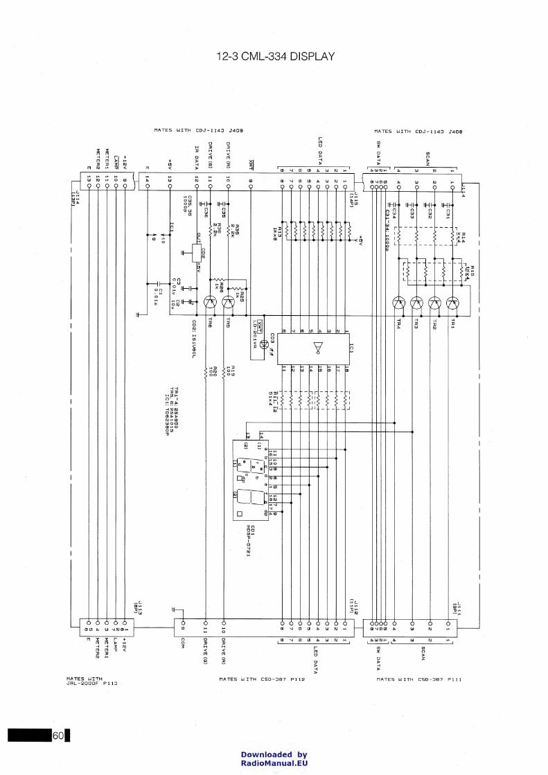
><(
_j
0.... C
f)
0 7 C0
C0 I
_j
~
ü C0 I
C\J r-
'" 0 .. .., (")
" ' .., Cl
u
I 1-H
3 U1 LU 1-<
I:
m
0 .. .., n .. ' .., C
l u
i': H
:I
U1 LU 1-<
(
I:
~
------
-------
~4
R1
5
R1
4
r1.!.<~4,
r>
r!S>s..4--, ~1 ~
1 l i
i ~C31
I I
~ .
~1 ~
TR
1
2 r>
I I
/1:>
:--•~
2
SCA
N
3 4
SW
DA
TA
[;
I I
r· V
V
V
*C
32
I
1 ---tf:__J
TR
2
-v
7'11 J
f 1--A
. I
\,I~
1 C3
3
1 I ~AAlJ
-tr:J T
R3
-Q
3"
I I
j I
I /1
:>:--
,-,. I
I I ,_ _:_ :.:-'
/1:>
:--4
~C34 L
-'
-tf:-_) T
R4
r<J
5;;?
: C
31
-34
: 1
00
0
6~ I
~X-" " -v
1 1 1
1
2 121
SC
AN
3 131
4 141
I~] sw
DA
TA
5 6 7 6
+5
V
~
..J1
15
J
11
2
-_p)
1
2 2
(14
P)
~AA-
IC1
I I
'"' 1
1 1
V
V
V
1 1
8
--,
2 2
~
2 l1
7
I
3 3
~
3 1
6
3 3
4 4
LE
D
DA
TA
5
5
LE
D
DA
TA
I4
4 ~
4
55
~
5
[)>o 1
5
c r ... -"-::::-, 1
4
6 6
7 7
6 16 I
6 6
~
6
7 7
[--vvv--7
6 6
~
6 111
I vv
I I
I I
I I
I I 7~;s
co3
A1
1,
12
l11l1ale
ls ls
l12l7 ls
] ........ 1111
51
x4
116115[;
[~ 11
J1BJ1714 fN
\ a
b_
c_
d
e f.____g_
dp
13
12
CD
1 I
I H
DS
P-5
72
1
l:liliil '<
:V
I ~
(1)
/f • I b I I
XM
T I
9 L
D-2
0 1 V
A
_!I_
--
1 ,_______g
( 2) I 1°
I I ~
~~
~ff
__ o
2.2
k
? -·/;-::;:.,--R
19
1
2 D
RIV
E (A
) I 1
0
TR
5
10
0
10
!D
RIV
E (R
) ;j;C
35
R
36
R
26
2
.2k
ik
R
20
D
RIV
E (G
) I 1
1
TR
S
10
0
;j;C3
6
CD
2
IR
DA
TA
I 12
O
UT
C3
5, 3
6
10
00
p
+5
V
± t
C3
C
2
+5
V 1
13
01
rc1
L0
°1
1"
10
"
CD
2:
IS
1U
60
L
TR
1"
'4:2
SA
95
0
TR
5.
6: 2
SA
10
15
IC
1: T
D6
23
80
P
rl['"'"'
..J1
13
~
C1
E
l14
19
IO.Oiu l (6
P) ~
+1
2V
sQi------------------------------------------------------------~
LA
MP 10Qi------------------------------------------------------------~
ME
TE
R1 11Qi------------------------------------------------------------~
ME
TE
A2 1
2Q
i-------------------------------------------------------------M
J
E~3 J
11
4
(13
P
--------
1 1
+1
2V
6 2
LA
MP
7 3
ME
TE
R!
4 IM
ET
ER
2
~ IE
n_
" '" (")
' 0 U1 u I 1-H
3 U1 LU 1-<
I:
N
-;;: " '" (")
' 0 U1 u :r: 1-H
3
U1 LU 1-<
I: ~ -n_ I 1-u
. H
Q
:IO
0 U
lN
LU
' 1
-J
"'"' I:'o
-0 (0
I
Downloaded by RadioManuai.EU

_j
w
z <(
0... I 0 1--
s (f)
1'co (Y
) I
0 (f)
0 (Y)
I C
\J r-
CD
1:P
G5
55
1K
Y
CD
11
. 12
:TL
SG
20
8
CD
2-9
, 13~16:AV5551K
CD
21
-32
: 15
15
85
POW
ER
A
MP
~"'
_d_1f C
01
'CV
I
(:~ --'-
--'-
~2 1
-;'2 o
-S
1
CD
21
CD22L~
E
-
PO
VSW
R
IO
d"'
~"'
d"'
CD
3 'C
V
I ~
CD
5'C
V
--'---'-
--'-,o
o-
,o
o-
~52)
I S3
CD23L~
1 2
3 ..
,1
2 3
4,
SCA
N
S4
CD
2.4
p.. C
D25
P·0
1
5 6
7 el
W1
01
P: 1
1
1(9
Pl
,1
2 3
4,
SW
OA
TA
I
vo
A
LC
S
ET
d"'
d"'
d"'
;,;-:; --'-~0
SB
C0
26
I I
CD
7 'C
V
I .;g;
--'---'-
~o-
~0
S7
co
2/
CD
2BL
P.,
' '---
1 2
3 .. 5
6 7
8
1 2
3 4
5 6
7 8
LED
DA
TA
I: 0 u 9
TU
NE
D
RIV
E
MA
TC
H
:111( "'"
' d
"' ~~
~
--'-
~92~ C
02
9
P1
02
10
11
-
"1
02
P1
12
(1
1P
)
0: C
l
1&1 1&1
>
>
H
H
0: 0
: 0
0
I T""" CO
-A
NT
i A
NT
2
AN
T3
AN
T4
d"'
d"'
d"'
d"'
CD
13
'CV
I
C~4 C
01
SC
"
I C~B
--'---'-
--'---'-
~1:l ~11o-
~12° ,o
o
S1
3
CD
30
C
D31L
r:> C
D3
2 P.,
C0
33
PC
E0
91
4
-----
Downloaded by RadioManuai.EU
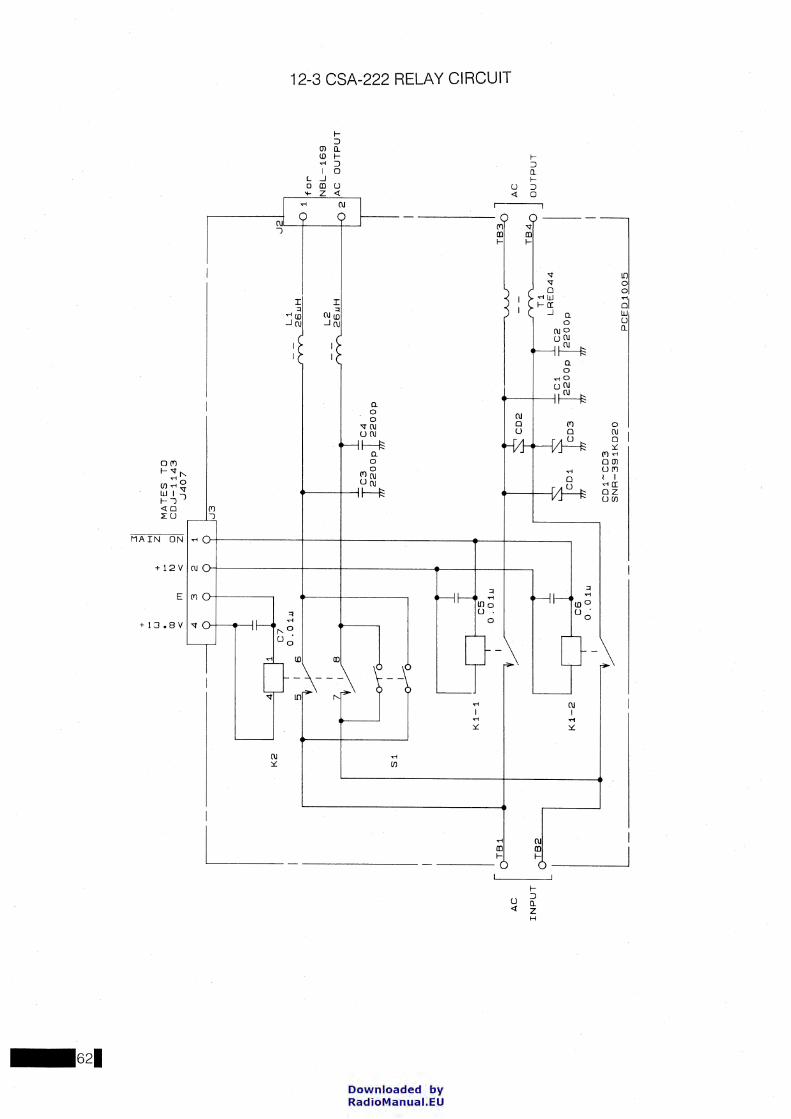
I (J) f\) -
AC
INP
UT
I I [o= l_
K2
+ w . aJ
<
+
1\J
MA
TE
S
TO
C
D.J
-11
43
0
40
7
CD
1-C
D3
S
NR
-39
1K
D2
0
1 'f
or
NB
L-1
69
2 ,A
C
OU
TP
UT
~] AC
~
I2~~0
I~ C
2
LR
ED
44
.
OU
TP
UT
p 2
20
0p
~I;Q_1005
--1
.
1\)
I w
0 (J)
)>
I 1\)
1
\)
1\)
::0
m ~ 0 ::0
0 c -1
Downloaded by RadioManuai.EU

(~RC) aapan Radio Co., .Iid.
Downloaded by RadioManuai.EU