
JR 11X SYSTEM - JR Americas · JR 11X SYSTEM WITH SPEKTRUM 2.4GHz DSM TECHNOLOGY INSTRUCTION AND...
23
JR 11X SYSTEM WITH SPEKTRUM 2.4GHz DSM TECHNOLOGY INSTRUCTION AND PROGRAMMING MANUAL The JR11X offers sophisticated programming features for three model types: airplanes, helicopters and sailplanes. This manual includes a section of common transmitter features and overall operational information, a section of model-specific programming and an appendix.
Transcript of JR 11X SYSTEM - JR Americas · JR 11X SYSTEM WITH SPEKTRUM 2.4GHz DSM TECHNOLOGY INSTRUCTION AND...

JR 11X SYSTEM WITH SPEKTRUM 2.4GHz DSM TECHNOLOGY
INSTRUCTION AND PROGRAMMING MANUAL
The JR11X offers sophisticated programming features for three model types: airplanes, helicopters and sailplanes. This manual includes a section of common transmitter features and overall operational information, a section of model-specific programming and an appendix.

2 JR 11X • RADIO INSTRUCTION MANUAL 3JR 11X • RADIO INSTRUCTION MANUAL
NOTICEAll instructions, warranties and other collateral documents are subject to change at the sole discretion of Horizon Hobby, Inc.
For up to date product literature, visit http://www.horizonhobby.com and click on the support tab for this product.
Meaning of Special Language:
The following terms are used throughout the product literature to indicate various levels of potential harm when operating this product:
NOTICE: Procedures, which if not properly followed, create a possibility of physical property damage AND a little or no possibility of injury.
CAUTION: Procedures, which if not properly followed, create the probability of physical property damage AND a possibility of serious injury.
WARNING: Procedures, which if not properly followed, create the probability of property damage, collateral damage, and serious injury OR create a high probability of superficial injury.
WARNING: Read the ENTIRE instruction manual to become familiar with the features of the product before operating. Failure to operate the product correctly can result in damage to the product, personal property and cause serious injury.
This is a sophisticated hobby product and NOT a toy. It must be operated with caution and common sense and requires some basic mechanical ability. Failure to operate this Product in a safe and responsible manner could result in injury or damage to the product or other property. This product is not intended for use by children without direct adult supervision. Do not attempt disassemble, use with incompatible components or augment product in any way without the approval of Horizon Hobby, Inc. This manual contains instructions for safety, operation and maintenance. It is essential to read and follow all the instructions and warnings in the manual, prior to assembly, setup or use, in order to operate correctly and avoid damage or serious injury.
TAbLE Of CONTENTS
TAbLE Of CONTENTS
Dual Channels ................................................................................................16Twin Engine ....................................................................................................17Flight Modes (Helicopter) ...............................................................................17Activating Extra Flight Modes 3 and 4 ............................................................17Switch Assignments .......................................................................................17Assigning/Activating Governor and Gyro Functions ......................................17Deactivating Channels ....................................................................................17Swashplate Type .............................................................................................18Flight Modes (Sailplane) ................................................................................18Activating and Assigning Primary Flight Modes ............................................18Activating and Assigning Additional Flight Modes ........................................18Motor Function ...............................................................................................19Flap and Aux Functions ..................................................................................19Activating/Inhibiting Channels .......................................................................19Wing Type .......................................................................................................19Flap Stick Direction ........................................................................................19function List ...............................................................................................19Dual Rate and Exponential ..............................................................................19Auto Function .................................................................................................20Travel Adjust ...................................................................................................20Limit Adjust ....................................................................................................20Sub-Trim .........................................................................................................20Servo Reversing .............................................................................................20Servo Speed ...................................................................................................20Throttle Curves (Airplane) ..............................................................................21Throttle Curves (Helicopter) ...........................................................................21Pitch Curve .....................................................................................................22Point Names/Numbers ...................................................................................22Current Point Settting .....................................................................................22Vertical Line ....................................................................................................22Graph ..............................................................................................................22Points You Can Add and Adjust .....................................................................22Exponential .....................................................................................................22Pitch Channel Position ...................................................................................22Throttle Channel Position ...............................................................................22Switch Select ..................................................................................................23Flap System ....................................................................................................23Flap .................................................................................................................23ELEV - Elevator Compensation .......................................................................23AILE - Aileron Compensation .........................................................................23Flight Modes ..................................................................................................23Delay ...............................................................................................................24Snap Roll ........................................................................................................24Differential ......................................................................................................24Aileron to Rudder............................................................................................24Aileron-to-Flap Mix ........................................................................................25Elevator to Flap ...............................................................................................25Rudder to Aileron/Elevator Mix ......................................................................25Trim (Mechanical Trim Lever) .........................................................................25Hovering Throttle ............................................................................................26Pitch Curve .....................................................................................................26Exponential .....................................................................................................26Hovering Pitch ................................................................................................26Tail Curve - (Use Only with Non-Heading Hold Gyros) ..................................26Throttle Hold ...................................................................................................27Stick Auto .......................................................................................................27Hold Delay ......................................................................................................27Gyro Sensor ....................................................................................................27Governor .........................................................................................................28Swash Mix ...................................................................................................28Aileron, Elevator and Pitch Authority ..............................................................28
Aileron to Elevator/Elevator to Aileron Mix .....................................................283D Electronic Cyclic Ring (E-Ring) ................................................................28Exponential Function ......................................................................................28Trim System ....................................................................................................28L.S.T. Trim (Limited Standard Trim) ................................................................29Slide Camber ..................................................................................................29Motor System .................................................................................................29 Camber Preset ................................................................................................29Landing Mode ................................................................................................30Differential ......................................................................................................30Flaperon Mix ..................................................................................................30Aileron-to-Rudder Mix ...................................................................................31Snap-to-Flap Mix ...........................................................................................31Rudder-to-Spoiler Mix....................................................................................31 Introduction to Mixers ..............................................................................31Functions of the Standard Programmable Mixer ............................................32Master Channel-(STD. PROG MIXER) ...........................................................32Slave Channel-(STD. PROG MIXER) ..............................................................32Switch Position ...............................................................................................32Offset ..............................................................................................................32Mix Values ......................................................................................................32CLR Button-(STD. PROG MIXER) Slave Channel ..........................................33To Inhibit a Mix ...............................................................................................33Multi-Point Programmable Mixer ..................................................................33Point Names/Numbers ...................................................................................33Current Point Setting ......................................................................................33Vertical Line ....................................................................................................33Graph ..............................................................................................................33Points You Can Add and Adjust .....................................................................33Exponential .....................................................................................................33Slave Channel Position ..................................................................................34Master Channel Position ................................................................................34Mix to Thottle .................................................................................................34Selecting the Desired Flight Modes for Cyclic-to-Throttle Mixing .................34F-Mode Delay .................................................................................................34Gyro Gain System [Sensor] ............................................................................34Gyro Connection ............................................................................................34Gyro Sensor [Gain] .........................................................................................34Trim System ....................................................................................................35L.S.T. Trim (Limited Standard Trim) ................................................................35Throttle Hold ...................................................................................................35Throttle Trim ...................................................................................................35Balance ...........................................................................................................36Stick Position Switch ......................................................................................36Timer ..............................................................................................................36Mix Monitor ....................................................................................................37Monitor ...........................................................................................................37Frequently Asked Questions on Spektrum 2.4GHz .........................................38General Information ........................................................................................39Warranty and Repair Policy ....................................................................393 Year Limited Warranty .................................................................................39Damage Limits................................................................................................39Warranty Services .....................................................................................41Questions, Assistance and Repairs.................................................................40Inspection or Repairs ......................................................................................40Warranty Inspection and Repairs ....................................................................41Non-warranty Repairs .....................................................................................41Appendix ......................................................................................................42Flight Log JRPA - Optional for Jr JR R921 Receiver ......................................42Advanced Range Testing .................................................................................43Control Stick Tension Adjustment ..................................................................43
JR 11X Transmitter and Receiver Specifications and features ......4ModelMatch .....................................................................................................4Advanced Digital Trims .....................................................................................4Compatible Receivers .......................................................................................4Charging ...........................................................................................................4The JR R921 .....................................................................................................5Binding .............................................................................................................6How to Bind ......................................................................................................6Failsafe Functions.............................................................................................6Range Testing ...................................................................................................6Receiver Power System Requirements .............................................................7Transmitter Identification (Mode 2) ..................................................................8Airplane Mode ..................................................................................................9Helicopter Mode ...............................................................................................9Sailplane Mode.................................................................................................9Initial Model Setup Guide ........................................................................10Trim Position Memory ....................................................................................10Quick Information Screen ...............................................................................10Quick Edit Mode .............................................................................................10System List ..................................................................................................10Function List ...................................................................................................10My List ............................................................................................................10
Accessing the System List ..............................................................................11Model Select ...................................................................................................11Copy ...............................................................................................................11Erase ...............................................................................................................12Type Select .....................................................................................................12Model Name ...................................................................................................12Flight Mode Name ..........................................................................................12Warning ..........................................................................................................13TX Settings .....................................................................................................13All Servos Hold...............................................................................................13Trainer .............................................................................................................1311X Used as Master .......................................................................................1411X Used as Slave ..........................................................................................14Stick Alert .......................................................................................................14Devise Select ..................................................................................................14Flight Modes (Airplane) ..................................................................................15Switch Assignments .......................................................................................15Active/Inhibit Channels ..................................................................................15Wing Type .......................................................................................................16V-Tail ..............................................................................................................16Dual Control Functions ..................................................................................16To Program a Wing Type ................................................................................16
JR 11X SYSTEM WITH SPEKTRUM 2.4GHz DSM TECHNOLOGY INSTRUCTION AND PROGRAMMING MANUAL
4 JR 11X • RADIO INSTRUCTION MANUAL 5JR 11X • RADIO INSTRUCTION MANUAL
JR 11X TRANSMITTER AND RECEIvER SPECIfICATIONS AND fEATURESWith Spektrum’s 2.4GHz DSM technology, the JR 11X offers a hassle-free, interference-free superior RF link for your airplane, helicopter or sailplane. The same technology also significantly reduces latency so you have a more responsive, precise connection to your aircraft. All of this means you can fly with confidence and safety when you fly with the 11X.
SYSTEM SPECIfICATIONSJR 11X Transmitter features: • Backlit screen • Digital 3 + 1 trims (3 digital + 1 analog [throttle] trim) • Dual ball bearings • Fully integrated 2.4GHz Spektrum™ technology • Sophisticated programming for three model types: Airplane, Helicopter, Sailplane • Rolling Selector input • Flight Mode naming • 30-model memory • Patented DuaLink® Technology • ModelMatch™ • ServoSync™ • Advanced Digital Trims
Transmitter Specifications: • Model Number: (11X 2.4, JRP1100) • Number of Channels: 11 • Modulation Type: Direct Sequence Spread Spectrum DSM2/ DSM1 protocol • Band: 2.400–2.483GHz • Transmitter Current: 180mA/DSM2; 280mA/DSM1 • Resolution: 2048
Receiver features:• Instant QuickConnect™ (with brownout detection) should a
power interruption occur • Flight Log compatible • 9 channels • 2 internal receivers• 1 remote receiver, a 2nd remote receiver is optional
(JRPRR121)• Patented MultiLink™ technology • Two Types of Failsafe: SmartSafe™ and Preset Failsafe
Receiver Specifications: • Number of Channels: 9 • Modulation: DSM2 • Band: 2.400–2.4835GHz • Dimensions (WxLxH): 1.23 x 1.94 x .56 in • Weight: Main .6 oz (15 g); Remote .2 oz (3 g) each • Current: 70mA • Voltage Range: 3.5 to 10V • Resolution: 2048
MODELMATCH Patent pending ModelMatch technology prevents the operation of your model, if you select the wrong model memory. During binding the receiver learns the
model’s memory (1 through 30) the transmitter is currently programmed to. Later, if you select the incorrect model memory in the transmitter and turn the receiver on, the model won’t operate. This prevents a possible crash. Change the programming to the correct model memory, and you can fly.
ADvANCED DIGITAL TRIMSThe 11X features Advanced digital trims. On the Normal display screen, if you move a trim lever, the screen automatically displays the graphic position for the trim being adjusted. The 11X Aileron, Elevator and Rudder trim levers and the right and left rear levers feature an audible center trim beep. This helps when determining the trim lever’s center position during flight. In addition, the frequency of each trim step changes from full right/up to full left/down on the three front digital trims. This allows you to be aware of the general trim position audibly without looking at the transmitter.
By using the Trim System Function located in the System List, you can adjust the amount of travel per each trim step as needed for your specific application. When you turn the 11X off, the transmitter stores the trim values and recalls them when turned back on.
COMPATIbLE RECEIvERS Note: The 11X is compatible with all current JR and Spektrum DSM aircraft receivers including:
• AR500 5-channel Parkflyer Receiver • AR6000 6-channel Parkflyer Receiver • AR6100 6-channel 3.5-gram Parkflyer Receiver • AR6100e 6-channel 3.5-gram End Pin Parkflyer Receiver • AR6110/AR6110E 6-channel Parkflyer Receiver/End Pin • AR6200 6-channel Full Range Receiver • AR6250 6-channel Carbon Fuse Full Range Receiver • AR6300 6-channel 2-gram Nanolite Slow and Micro Flyer Receiver • AR6400/L 6-channel Receiver • AR7000 7-channel Full Range Receiver • AR7600 7-channel High-Speed Receiver • AR7100/AR7100R 7-channel Heli Receiver/with RevLimit™ • AR9000 9-channel Receiver • AR9100 9-channel PowerSafe™ Receiver • AR9200 9-channel PowerSafe Evolution Receiver • AR9300 9-channel Carbon Fuse Receiver • AR12000 12-channel Receiver • AR12100 12-channel PowerSafe Receiver • R922 9-channel PowerSafe Receiver • R1221 12-channel Receiver • R1222 12-channel PowerSafe Receiver
CAUTION: When using the 11X with slow and park flyer receivers (the AR6000, AR6100, AR6100e, AR6110, AR6110E, AR6300, AR6400 and
AR7600 when the remote receiver is not connected), you should only fly these receivers in park flyer-type aircraft (small electric airplanes or mini and micro helicopters). Flying receivers designed for park flyers in larger aircraft could cause a loss of control resulting in damage to property and/or injury.
CHARGING Do’s and Don’ts• Chargetransmitterandreceiverbatterybeforeflying.• Checkreceiverbatterychargebetweeneachflightusingatesterwithbuilt-in
load.• OnlyusechargeronJRequipment.Chargeplugpolaritymaybedifferent.
Equipment damage can result.• Donotuseothermanufacturer’safter-marketaccessoriesthatpluginto
transmitter charging jack. If you doubt polarity compatibility, seek expert advice to avoid possible damage.
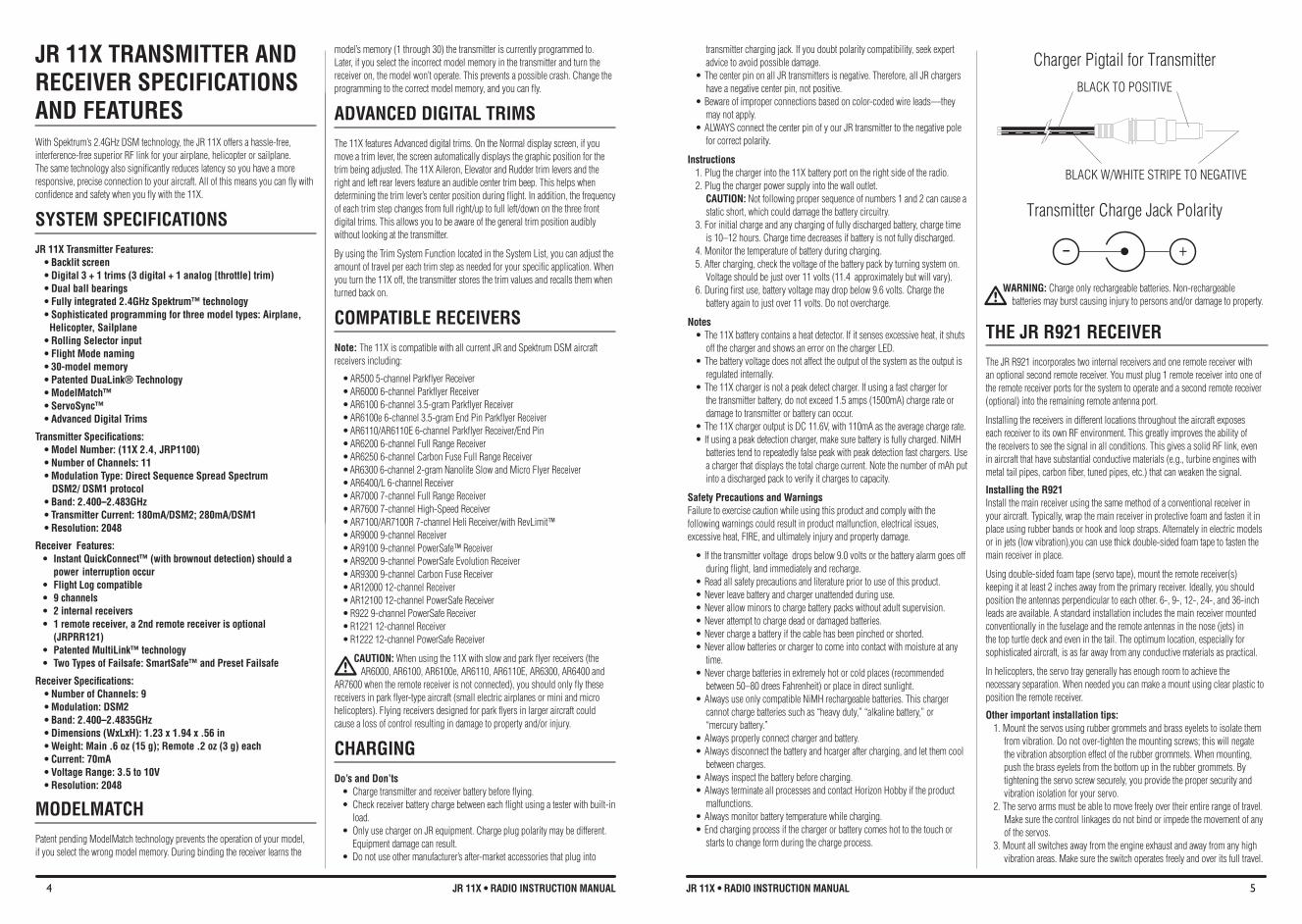
•ThecenterpinonallJRtransmittersisnegative.Therefore,allJRchargershave a negative center pin, not positive.
•Bewareofimproperconnectionsbasedoncolor-codedwireleads—theymay not apply.
•ALWAYSconnectthecenterpinofyourJRtransmittertothenegativepolefor correct polarity.
Instructions1. Plug the charger into the 11X battery port on the right side of the radio.2. Plug the charger power supply into the wall outlet.
CAUTION: Not following proper sequence of numbers 1 and 2 can cause a static short, which could damage the battery circuitry.
3. For initial charge and any charging of fully discharged battery, charge time is 10–12 hours. Charge time decreases if battery is not fully discharged.
4. Monitor the temperature of battery during charging.5. After charging, check the voltage of the battery pack by turning system on.
Voltage should be just over 11 volts (11.4 approximately but will vary).6. During first use, battery voltage may drop below 9.6 volts. Charge the
battery again to just over 11 volts. Do not overcharge.
Notes•The11Xbatterycontainsaheatdetector.Ifitsensesexcessiveheat,itshuts
off the charger and shows an error on the charger LED.•Thebatteryvoltagedoesnotaffecttheoutputofthesystemastheoutputis
regulated internally.•The11Xchargerisnotapeakdetectcharger.Ifusingafastchargerfor
the transmitter battery, do not exceed 1.5 amps (1500mA) charge rate or damage to transmitter or battery can occur.
•The11XchargeroutputisDC11.6V,with110mAastheaveragechargerate.•Ifusingapeakdetectioncharger,makesurebatteryisfullycharged.NiMH
batteries tend to repeatedly false peak with peak detection fast chargers. Use a charger that displays the total charge current. Note the number of mAh put into a discharged pack to verify it charges to capacity.
Safety Precautions and WarningsFailure to exercise caution while using this product and comply with the following warnings could result in product malfunction, electrical issues, excessive heat, FIRE, and ultimately injury and property damage.
•Ifthetransmittervoltagedropsbelow9.0voltsorthebatteryalarmgoesoffduring flight, land immediately and recharge.
•Readallsafetyprecautionsandliteraturepriortouseofthisproduct.•Neverleavebatteryandchargerunattendedduringuse.•Neverallowminorstochargebatterypackswithoutadultsupervision.•Neverattempttochargedeadordamagedbatteries.•Neverchargeabatteryifthecablehasbeenpinchedorshorted.•Neverallowbatteriesorchargertocomeintocontactwithmoistureatany
time.•Neverchargebatteriesinextremelyhotorcoldplaces(recommended
between 50–80 drees Fahrenheit) or place in direct sunlight.•AlwaysuseonlycompatibleNiMHrechargeablebatteries.Thischarger
cannot charge batteries such as “heavy duty,” “alkaline battery,” or “mercury battery.”
•Alwaysproperlyconnectchargerandbattery.•Alwaysdisconnectthebatteryandhcargeraftercharging,andletthemcool
between charges.•Alwaysinspectthebatterybeforecharging.•AlwaysterminateallprocessesandcontactHorizonHobbyiftheproduct
malfunctions.•Alwaysmonitorbatterytemperaturewhilecharging.•Endchargingprocessifthechargerorbatterycomeshottothetouchor
starts to change form during the charge process.
WARNING: Charge only rechargeable batteries. Non-rechargeable batteries may burst causing injury to persons and/or damage to property.
THe JR R921 ReCeIVeR The JR R921 incorporates two internal receivers and one remote receiver with an optional second remote receiver. You must plug 1 remote receiver into one of the remote receiver ports for the system to operate and a second remote receiver (optional) into the remaining remote antenna port.
Installing the receivers in different locations throughout the aircraft exposes each receiver to its own RF environment. This greatly improves the ability of the receivers to see the signal in all conditions. This gives a solid RF link, even in aircraft that have substantial conductive materials (e.g., turbine engines with metal tail pipes, carbon fiber, tuned pipes, etc.) that can weaken the signal.
Installing the R921Install the main receiver using the same method of a conventional receiver in your aircraft. Typically, wrap the main receiver in protective foam and fasten it in place using rubber bands or hook and loop straps. Alternately in electric models or in jets (low vibration),you can use thick double-sided foam tape to fasten the main receiver in place.
Using double-sided foam tape (servo tape), mount the remote receiver(s) keeping it at least 2 inches away from the primary receiver. Ideally, you should position the antennas perpendicular to each other. 6-, 9-, 12-, 24-, and 36-inch leads are available. A standard installation includes the main receiver mounted conventionally in the fuselage and the remote antennas in the nose (jets) in the top turtle deck and even in the tail. The optimum location, especially for sophisticated aircraft, is as far away from any conductive materials as practical.
In helicopters, the servo tray generally has enough room to achieve the necessary separation. When needed you can make a mount using clear plastic to position the remote receiver.
Other important installation tips: 1. Mount the servos using rubber grommets and brass eyelets to isolate them
from vibration. Do not over-tighten the mounting screws; this will negate the vibration absorption effect of the rubber grommets. When mounting, push the brass eyelets from the bottom up in the rubber grommets. By tightening the servo screw securely, you provide the proper security and vibration isolation for your servo.
2. The servo arms must be able to move freely over their entire range of travel. Make sure the control linkages do not bind or impede the movement of any of the servos.
3. Mount all switches away from the engine exhaust and away from any high vibration areas. Make sure the switch operates freely and over its full travel.
Charger Pigtail for Transmitter
Transmitter Charge Jack Polarity
BLACK TO POSITIVE
BLACK W/WHITE STRIPE TO NEGATIVE
- +
6 JR 11X • RADIO INSTRUCTION MANUAL 7JR 11X • RADIO INSTRUCTION MANUAL
RECEIvER POWER SYSTEM ReQUIReMeNTS The onboard power system must provide adequate power without interruption to the receiver even when the servos are at maximum flight loads. Inadequate power systems that do not provide the necessary minimum voltage to the receiver during flight loads are the number one cause of in-flight failures. Some power system components that affect the ability to properly deliver adequate power include: the selected receiver battery pack (number of cells, capacity, cell type, state of charge), switch harness, battery leads, and if used, the regulator and power bus.
Recommended Power System Guidelines 1. When setting up large or complex aircraft with multiple high-torque servos,
you should use a current and voltmeter (HAN172). Plug the voltmeter in an open channel port in the receiver and, with the system on, load the control surfaces (apply pressure with your hand). Monitor the voltage at the receiver. The voltage should remain above 4.8 volts even when all servos are heavily loaded. The optional Flight Log has a built-in voltmeter and can be used.
2. With the current meter in line with the receiver battery lead, load the control surfaces while monitoring the current. The maximum continuous recommended current for a single heavy-duty servo/battery lead is three amps. Short duration current spikes of up to five amps are acceptable. If your system draws more than these currents, you should use multiple packs with multiple switches and multiple leads plugged into the receiver. While a JR receiver’s minimum operational voltage is 3.5 volts, you should test the system to a minimum acceptable voltage of 4.8 volts during ground testing. This provides headroom to compensate for battery discharging or if the actual flight loads are greater than the ground test loads. Note: JR’s amplified Y-harness (JRPA133) is for use with Z-PCM only. JR’s non- amplified Y-harness (JRPA135) should be used with PPM, SPCM or DSM/DSM2 systems.
3. If using a regulator, perform the above tests for an extended period of 5 minutes. When current passes through a regulator, heat is generated. This causes the regulator to increase resistance, causing even more heat to build up (thermal runaway). While a regulator may provide adequate power for a short duration, you should test its ability over time. The regulator may not be able to maintain voltage at significant power levels.
4. For really large aircraft or complex models (for example 35% and larger or jets), multiple battery packs with multiple switch harnesses are necessary or, in many cases, one of the commercially available power boxes/busses is recommended. No matter what power system you choose, always carry out test #1 above. Make sure the receiver is constantly provided with 4.8 volts or more under all conditions.
bINDING
Binding is necessary to program the receiver to the transmitter so the receiver only recognizes that specific transmitter, ignoring signals from any other sources. If the receiver is not bound to the transmitter, the system will not operate. During binding, the servo’s failsafe positions are stored. The following sequence describes the binding procedure for the JR R921. All JR and Spektrum DSM aircraft receivers are bound in the same way.
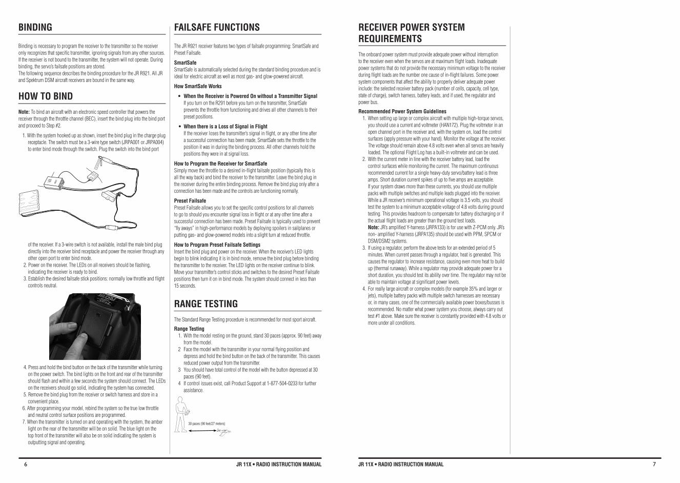
HOW TO bIND Note: To bind an aircraft with an electronic speed controller that powers the receiver through the throttle channel (BEC), insert the bind plug into the bind port and proceed to Step #2.
1. With the system hooked up as shown, insert the bind plug in the charge plug receptacle. The switch must be a 3-wire type switch (JRPA001 or JRPA004) to enter bind mode through the switch. Plug the switch into the bind port
of the receiver. If a 3-wire switch is not available, install the male bind plug directly into the receiver bind receptacle and power the receiver through any other open port to enter bind mode.
2. Power on the receiver. The LEDs on all receivers should be flashing, indicating the receiver is ready to bind.
3. Establish the desired failsafe stick positions: normally low throttle and flight controls neutral.
4. Press and hold the bind button on the back of the transmitter while turning on the power switch. The bind lights on the front and rear of the transmitter should flash and within a few seconds the system should connect. The LEDs on the receivers should go solid, indicating the system has connected.
5. Remove the bind plug from the receiver or switch harness and store in a convenient place.
6. After programming your model, rebind the system so the true low throttle and neutral control surface positions are programmed.
7. When the transmitter is turned on and operating with the system, the amber light on the rear of the transmitter will be on solid. The blue light on the top front of the transmitter will also be on solid indicating the system is outputting signal and operating.
fAILSAfE fUNCTIONS
The JR R921 receiver features two types of failsafe programming: SmartSafe and Preset Failsafe.
SmartSafeSmartSafe is automatically selected during the standard binding procedure and is ideal for electric aircraft as well as most gas- and glow-powered aircraft.
How SmartSafe Works
• When the Receiver is Powered On without a Transmitter Signal If you turn on the R291 before you turn on the transmitter, SmartSafe prevents the throttle from functioning and drives all other channels to their preset positions.
• When there is a Loss of Signal in flight If the receiver loses the transmitter’s signal in flight, or any other time after a successful connection has been made, SmartSafe sets the throttle to the position it was in during the binding process. All other channels hold the positions they were in at signal loss.
How to Program the Receiver for SmartSafe Simply move the throttle to a desired in-flight failsafe position (typically this is all the way back) and bind the receiver to the transmitter. Leave the bind plug in the receiver during the entire binding process. Remove the bind plug only after a connection has been made and the controls are functioning normally.
Preset failsafePreset Failsafe allows you to set the specific control positions for all channels to go to should you encounter signal loss in flight or at any other time after a successful connection has been made. Preset Failsafe is typically used to prevent “fly aways” in high-performance models by deploying spoilers in sailplanes or putting gas- and glow-powered models into a slight turn at reduced throttle.
How to Program Preset failsafe SettingsInsert the bind plug and power on the receiver. When the receiver’s LED lights begin to blink indicating it is in bind mode, remove the bind plug before binding the transmitter to the receiver. The LED lights on the receiver continue to blink. Move your transmitter’s control sticks and switches to the desired Preset Failsafe positions then turn it on in bind mode. The system should connect in less than 15 seconds.
RANGE TESTING The Standard Range Testing procedure is recommended for most sport aircraft.
Range Testing 1. With the model resting on the ground, stand 30 paces (approx. 90 feet) away
from the model. 2 Face the model with the transmitter in your normal flying position and
depress and hold the bind button on the back of the transmitter. This causes reduced power output from the transmitter.
3 You should have total control of the model with the button depressed at 30 paces (90 feet).
4 If control issues exist, call Product Support at 1-877-504-0233 for further assistance.
30 paces (90 feet/27 meters)
R92
1
8 JR 11X • RADIO INSTRUCTION MANUAL 9JR 11X • RADIO INSTRUCTION MANUAL
The ACRO mode is for powered fixed-wing aircraft. It contains advanced features designed to assist the pilot in realizing the full potential of the aircraft. These features include: • Upto3flightmodes• Switchandleverassignability• TripleRatesandExponentialsforAileron,ElevatorandRudderthatcanbe
combined or assigned to flight modes • 4programmableWingTypes(Normal,Flaperon,Delta,4-aileron)• Differentialwithtwovaluesperchannel(Aileron,DualRudder,DualFlap)• V-Tailmixing• DualChannelsforAllPrimaryFlightControlsandFlaps• DualThrottles(WithIndependentTrimsandThrottleCurves)• AdjustableTrimRates(10–100TrimSteps)• L.S.T.trim—trimcanbeprogrammedtoaffectendpointsorcenterpoint
only• Elevator-To-Flapmixing• Aileron-To-Flapmixing
• Balancemixingallowsprecisemixingofslavechanneltomasteratmultiplepoints
• Throttlehold—canbeassignedasakillswitch• Aileron-To-Ruddermixing• ThrottleCurves(2)• FlapSystem(WithElevatorandAileronTrim,AutoLand,Elevator/Flap
Delay) • GyroSystem(In-FlightGainSelectionofupto3Gainsforupto2Gyros)• ServoSpeed(IndependentinBothDirections–EliminatesDoor
Sequencers) • 6ProgrammableMixes(Includes3Multi-PointMixes)• ProgrammableTrainerSystem(SelectableChannelsforStudentControl)• Timers-uptofour(Stopwatch,Countdown,Integrated)• ServoMonitor(AutomaticallyRenamesChannelsAccordingto
Assignments) • PitchCurveMixingforvariablepitchprops
AIRPLANE - ACRO MODE
The 11X Heli Mode programming includes 6 swashplate types making it compatible with virtually every type of model helicopter. Some of the 11X’s sophisticated Heli programming features include: • SwitchAssignabilityforchannelsandfunctions• UptosixfullyprogrammableFlightModes• FlightModeNamingallowscustomnamingofeachflightmode.•Warningsystemallowscustomprogrammingofalarmsforvariousswitch
and stick positions • ProgrammableServoSpeed• TripleRates/Exponentials(upto4Rates/EXPOsforAileron,Elevatorand
Rudder in flight modes) • 6SwashplateTypes(normal,2servo180,3servo120,3servo140,3servo
90, 4 servo 90) • Electronic3DCyclicRingpreventsoverdrivingthecyclicservoswith
combined aileron and elevator commands • AdjustableTrimRates(10–100trimsteps)• Built-InCyclic-to-ThrottleMixingforAileron,Elevator,andRudder• GovernorMix• ThrottleCurves(upto5)withupto7programmablepoints• PitchCurves(upto6)withupto7programmablepoints• GyroSystem(InFlightmodeGainSelectionofupto6gains)• 6ProgrammableMixes(includes3multi-pointand3standardmixes)• Programmabletrainersystem(selectablechannelsforStudentControl)• 3programmabletimersthatcanbetriggeredw/thethrottlepositionor
programmable switches • ServoMonitor(automaticallyrenameschannelsaccordingtoassignments)• MixMonitordisplaysallactivemixes
HELICOPTER MODE
The 11X GLID programming is optimized for multi-function sailplanes and offers the highest level of versatility and sophistication. The system has many features including:• SwitchAssignabilityforchannelsandfunctions• Upto5fullyprogrammableFlightModes• FlightModeNamingallowscustomnamingofeachflightmode• Dualcontrolfunctionsforelevator,rudder,flapandspoilers• V-tailmixing• StickPositionswitchesallowmixingfunctionstobeturnedon/offviaastick
position • Fullyprogrammablemotorfunction• Camberprogrammingforeachflightmode
• Warningsystemallowscustomprogrammingofalarmsforvariousswitchand stick positions
• Programmableservospeed• TripleRates/Exponentials(upto4Rates/EXPOsforAileron,Elevatorand
Rudder in flight modes) • AdjustableTrimRates(10–100TrimSteps)• 6ProgrammableMixes(includes3Multi-Pointand3Standardmixes)• ProgrammableTrainersystem(selectablechannelsforstudentcontrol)• 3ProgrammableTimersthatcanbetriggeredwiththethrottlepositionor
programmable switches • ServoMonitor(automaticallyrenameschannelsaccordingtoassignments)• MixMonitordisplaysallactivemixes
SAILPLANE MODE
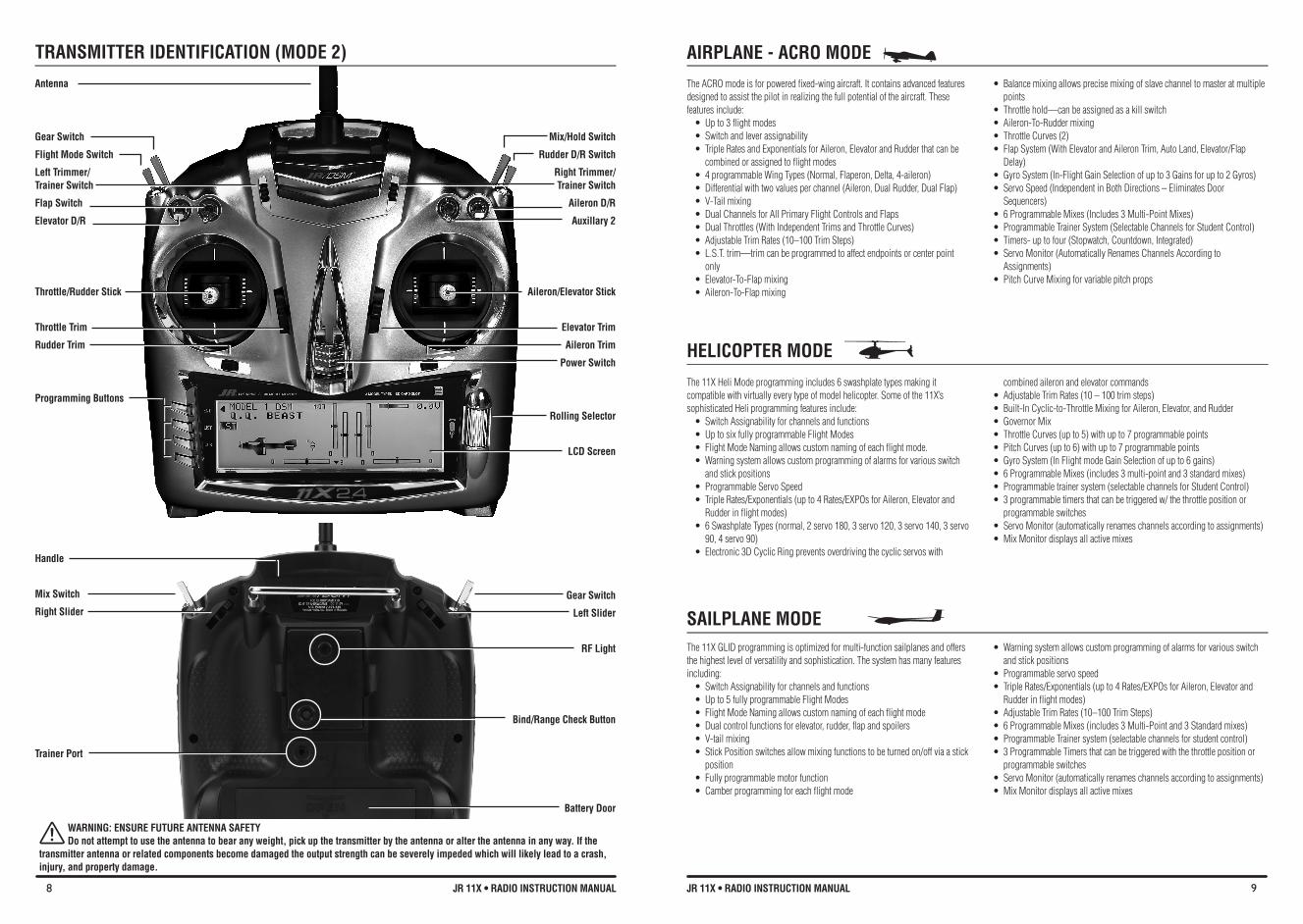
TRANSMITTeR IDeNTIFICATION (MODe 2)
Antenna
Gear Switch
flight Mode Switch
Left Trimmer/ Trainer Switch
flap Switch
Elevator D/R
Throttle/Rudder Stick
Throttle Trim
Rudder Trim
Programming buttons
Handle
Mix Switch
Right Slider
Trainer Port
Mix/Hold Switch
Rudder D/R Switch
Right Trimmer/ Trainer Switch
Aileron D/R
Auxillary 2
Aileron/elevator Stick
Elevator Trim
Aileron Trim
Power Switch
Rolling Selector
LCD Screen
Gear Switch
Left Slider
Rf Light
Bind/Range Check Button
battery Door
WARNING: ENSURE fUTURE ANTENNA SAfETY Do not attempt to use the antenna to bear any weight, pick up the transmitter by the antenna or alter the antenna in any way. If the transmitter antenna or related components become damaged the output strength can be severely impeded which will likely lead to a crash, injury, and property damage.
10 JR 11X • RADIO INSTRUCTION MANUAL 11JR 11X • RADIO INSTRUCTION MANUAL
To enter My List, on the main display screen or in the Function List, highlight and select My List. Push the lower left button down to enter Edit Mode or highlight and select Edit Mode with the Roller. Highlight and select each menu location as desired, then highlight and select the programming function desired for that location. Repeat for all functions desired to place into My List. When finished, push the lower left button down or highlight and select OK to exit Edit Mode and enter My List. Push the LIST key down to return to the main screen.
ACCESSING THE SYSTEM LIST
Programming a new model generally begins by accessing the System List. The system list can be accessed two ways. Press list button, then using the rolling selector scroll until System List appears in the lower right corner of the screen and press enter. System list can also be entered by pressing the enter button while turning on the transmitter. System Mode is where you select models, choose the model type (airplane, helicopter or sailplane) and program other high-level information.
MODEL SELECT
Model select allows you to program, store and select up to 30 different individual model memories. Note: When setting up a new model, use an unused model memory. If a current model memory is selected, reset the model to the factory default setting before programming a new model.
To select a Model Memory1. In the System List, use the Roller to highlight and select Model Select.2. Highlight MODEL then select the desired model number.
COPY
The 11X can copy data to or from another 11X or SD Card. With the 11X system you can transfer data to or from the internal memory to an SD Card, or transfer data to or from one 11X’s Internal memory or SD Card. And making a backup copy of the model memory protects against losing the original program and allows you to experiment with the original program, by copying the backup copy back to the original model memory. You can restore the original settings any time.
To Copy a Model to another 11X transmitter or to an SD CardThe TRANSFER function allows the 11X transmitter to transfer a model memory to another 11X transmitter or to an SD Card. This allows for unlimited model memory storage and backup of your model’s programming. You can also use the Transfer function to receive data from another 11X or SD Card.Note: The sending and receiving transmitters must both be 11X’s or an SD Card from an 11X. Transfer is not possible from any other system.
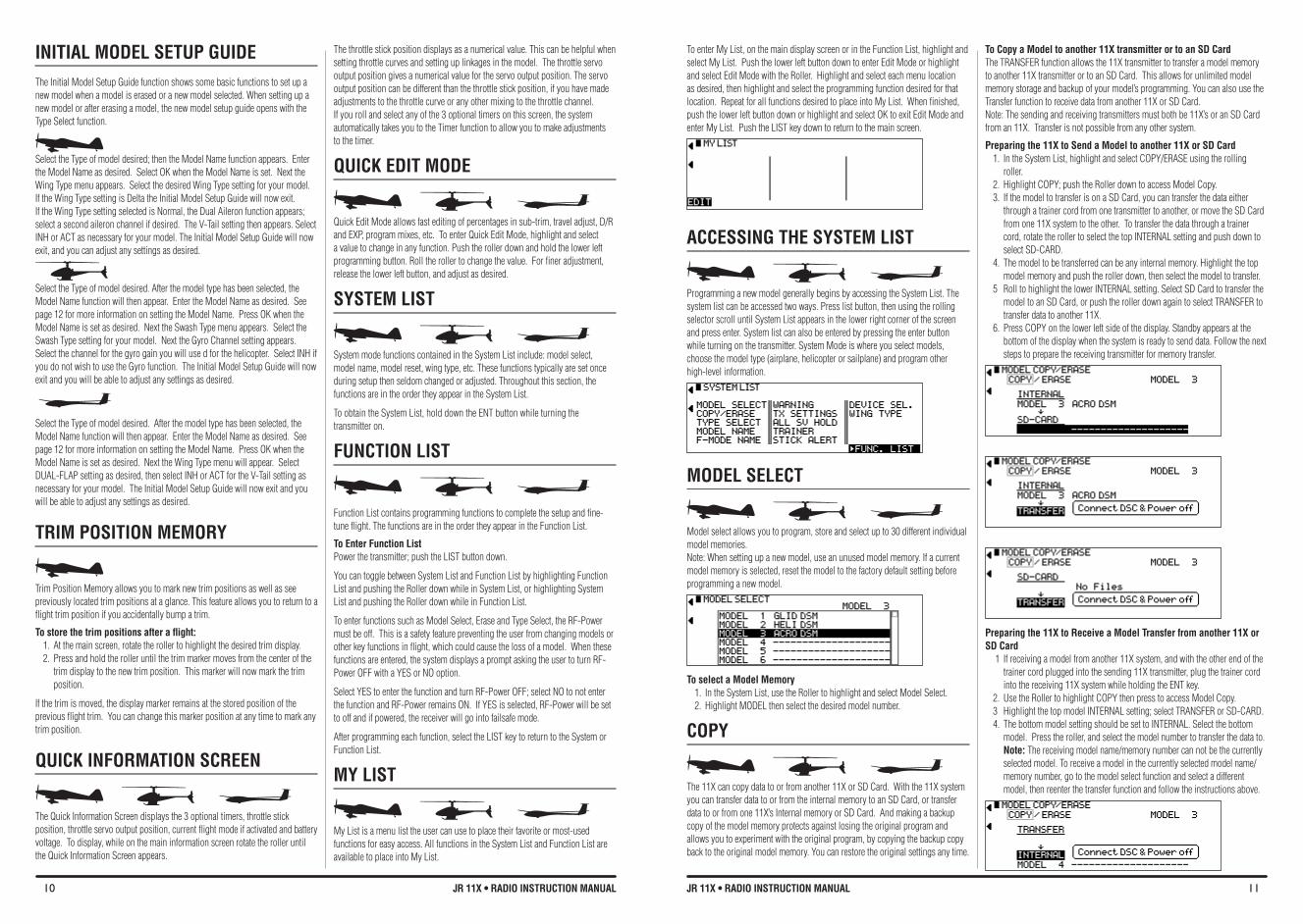
Preparing the 11X to Send a Model to another 11X or SD Card1. In the System List, highlight and select COPY/ERASE using the rolling
roller.2. Highlight COPY; push the Roller down to access Model Copy. 3. If the model to transfer is on a SD Card, you can transfer the data either
through a trainer cord from one transmitter to another, or move the SD Card from one 11X system to the other. To transfer the data through a trainer cord, rotate the roller to select the top INTERNAL setting and push down to select SD-CARD.
4. The model to be transferred can be any internal memory. Highlight the top model memory and push the roller down, then select the model to transfer.
5 Roll to highlight the lower INTERNAL setting. Select SD Card to transfer the model to an SD Card, or push the roller down again to select TRANSFER to transfer data to another 11X.
6. Press COPY on the lower left side of the display. Standby appears at the bottom of the display when the system is ready to send data. Follow the next steps to prepare the receiving transmitter for memory transfer.
Preparing the 11X to Receive a Model Transfer from another 11X or SD Card
1 If receiving a model from another 11X system, and with the other end of the trainer cord plugged into the sending 11X transmitter, plug the trainer cord into the receiving 11X system while holding the ENT key.
2. Use the Roller to highlight COPY then press to access Model Copy. 3 Highlight the top model INTERNAL setting; select TRANSFER or SD-CARD.4. The bottom model setting should be set to INTERNAL. Select the bottom
model. Press the roller, and select the model number to transfer the data to. Note: The receiving model name/memory number can not be the currently selected model. To receive a model in the currently selected model name/memory number, go to the model select function and select a different model, then reenter the transfer function and follow the instructions above.
INITIAL MODEL SETUP GUIDEThe Initial Model Setup Guide function shows some basic functions to set up a new model when a model is erased or a new model selected. When setting up a new model or after erasing a model, the new model setup guide opens with the Type Select function.
Select the Type of model desired; then the Model Name function appears. Enter the Model Name as desired. Select OK when the Model Name is set. Next the Wing Type menu appears. Select the desired Wing Type setting for your model. If the Wing Type setting is Delta the Initial Model Setup Guide will now exit. If the Wing Type setting selected is Normal, the Dual Aileron function appears; select a second aileron channel if desired. The V-Tail setting then appears. Select INH or ACT as necessary for your model. The Initial Model Setup Guide will now exit, and you can adjust any settings as desired.
Select the Type of model desired. After the model type has been selected, the Model Name function will then appear. Enter the Model Name as desired. See page 12 for more information on setting the Model Name. Press OK when the Model Name is set as desired. Next the Swash Type menu appears. Select the Swash Type setting for your model. Next the Gyro Channel setting appears. Select the channel for the gyro gain you will use d for the helicopter. Select INH if you do not wish to use the Gyro function. The Initial Model Setup Guide will now exit and you will be able to adjust any settings as desired.
Select the Type of model desired. After the model type has been selected, the Model Name function will then appear. Enter the Model Name as desired. See page 12 for more information on setting the Model Name. Press OK when the Model Name is set as desired. Next the Wing Type menu will appear. Select DUAL-FLAP setting as desired, then select INH or ACT for the V-Tail setting as necessary for your model. The Initial Model Setup Guide will now exit and you will be able to adjust any settings as desired.
TRIM POSITION MEMORY
Trim Position Memory allows you to mark new trim positions as well as see previously located trim positions at a glance. This feature allows you to return to a flight trim position if you accidentally bump a trim.
To store the trim positions after a flight:1. At the main screen, rotate the roller to highlight the desired trim display. 2. Press and hold the roller until the trim marker moves from the center of the
trim display to the new trim position. This marker will now mark the trim position.
If the trim is moved, the display marker remains at the stored position of the previous flight trim. You can change this marker position at any time to mark any trim position.
QUICk INFORMATION SCReeN
The Quick Information Screen displays the 3 optional timers, throttle stick position, throttle servo output position, current flight mode if activated and battery voltage. To display, while on the main information screen rotate the roller until the Quick Information Screen appears.
The throttle stick position displays as a numerical value. This can be helpful when setting throttle curves and setting up linkages in the model. The throttle servo output position gives a numerical value for the servo output position. The servo output position can be different than the throttle stick position, if you have made adjustments to the throttle curve or any other mixing to the throttle channel. If you roll and select any of the 3 optional timers on this screen, the system automatically takes you to the Timer function to allow you to make adjustments to the timer.
QUICk eDIT MODe
Quick Edit Mode allows fast editing of percentages in sub-trim, travel adjust, D/R and EXP, program mixes, etc. To enter Quick Edit Mode, highlight and select a value to change in any function. Push the roller down and hold the lower left programming button. Roll the roller to change the value. For finer adjustment, release the lower left button, and adjust as desired.
SYSTEM LIST
System mode functions contained in the System List include: model select, model name, model reset, wing type, etc. These functions typically are set once during setup then seldom changed or adjusted. Throughout this section, the functions are in the order they appear in the System List.
To obtain the System List, hold down the ENT button while turning the transmitter on.
fUNCTION LIST
Function List contains programming functions to complete the setup and fine-tune flight. The functions are in the order they appear in the Function List.
To Enter function List Power the transmitter; push the LIST button down.
You can toggle between System List and Function List by highlighting Function List and pushing the Roller down while in System List, or highlighting System List and pushing the Roller down while in Function List.
To enter functions such as Model Select, Erase and Type Select, the RF-Power must be off. This is a safety feature preventing the user from changing models or other key functions in flight, which could cause the loss of a model. When these functions are entered, the system displays a prompt asking the user to turn RF-Power OFF with a YES or NO option.
Select YES to enter the function and turn RF-Power OFF; select NO to not enter the function and RF-Power remains ON. If YES is selected, RF-Power will be set to off and if powered, the receiver will go into failsafe mode.
After programming each function, select the LIST key to return to the System or Function List.
MY LIST
My List is a menu list the user can use to place their favorite or most-used functions for easy access. All functions in the System List and Function List are available to place into My List.
12 JR 11X • RADIO INSTRUCTION MANUAL 13JR 11X • RADIO INSTRUCTION MANUAL
ERASE
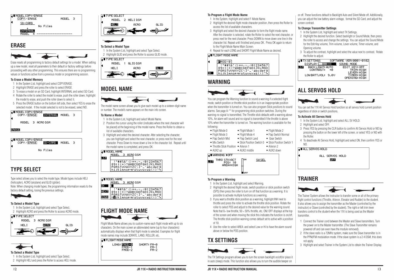
Erase resets all programming to factory default settings for a model. When setting up a new model, reset all parameters to their default or factory settings before proceeding with any other programming. This ensures there are no programming values or functions active from a previous model or programming session.
To Erase a Model Memory 1 In the System List, highlight and select COPY/ERASE. 2 Highlight ERASE and press the roller to select ERASE.3 To erase a model on an SD Card, highlight INTERNAL and select SD Card.4 Rotate the roller to select the model to erase, push the roller down, highlight
the model to erase, and push the roller down to select it.5 Press the ERASE button on the bottom left side, then select YES to erase the
selected model. If the model selected is not to be erased, select NO.
TYPE SELECT Type select allows you to select the model type. Model types include HELI (helicopter), ACRO (airplane) and GLID (glider). Note: When changing model types, the programming information resets to the factory default setting, losing the previous settings.
To Select a Model Type 1 In the System List, highlight and select Type Select. 2 Highlight ACRO and press the Roller to access ACRO mode.
To Select a Model Type 1 In the System List, highlight and select Type Select. 2 Highlight HELI and press the Roller to access HELI mode.
To Select a Model Type 1 In the System List, highlight and select Type Select. 2 Highlight GLID and press the Roller to access GLID mode.
MODEL NAME
The model name screen allows you to give each model up to a sixteen-digit name or number. The model’s name appears on the main info screen.
To Name a Model 1 In the System List, highlight and select Model Name. 2 Position the cursor using the roller (indicates where the next character will
be placed) at the beginning of the model name. Press the Roller to obtain a list of available characters.
3 Highlight and select the desired character. After selecting the character, you can highlight and select the next character, or press next for the next character. Press Down to move down a line in the character list. Repeat until the model name is completed, and press OK.
fLIGHT MODE NAME
Flight Mode Name allows you to custom-name each flight mode with up to six characters. On the main screen an abbreviated name (up to four characters) automatically displays when that flight mode is selected. Examples for flight mode names may include 3DRATE, LAND, ROLLER, etc.
To Program a flight Mode Name 1 In the System, highlight and select F-Mode Name. 2 Highlight the desired flight mode character position, then press the Roller to
access the list of available characters. 3 Highlight and select the desired character to form the flight mode name.
After the character is selected, rotate the Roller to select the next character, or press next for the next character. Press DOWN to move down one line in the character list. Repeat until finished and press OK. Press OK again to return to the Flight Mode Name Main Screen.
4 Repeat for each LONG and SHORT Flight Mode Name as desired.
WARNING
You can program the Warning function to sound a warning if a selected flight mode, switch position or throttle stick position is in an inappropriate position when the transmitter is turned on. You can also program Stick positions to sound alarms. See page A-** for programming stick position switches. During the warning no signal is transmitted. The Throttle stick defaults with a warning above 10%. An alarm will sound and no signal is transmitted if the throttle is above 10% when the transmitter is turned on. The warning function is available for the following: •FlightMode0 •FlightMode1 •FlightMode2•FlightMode3 •FlightMode4 •FlapSwitchNormal•FlapSwitchMid •FlapSwitchLand •GearSwitch•MixSwitch •StickPositionSwitch0 •StickPositionSwitch1•ThrottleStickPosition•Aileron1 •Aileron2•AUX2up •AUX2middle •AUX2down
To Program a Warning 1 In the System List, highlight and select Warning. 2 Highlight the desired flight mode, switch position or stick position switch
(SPS) then press the roller to turn on off that function as a warning. It is possible to activate multiple functions as a warning.
3 If you want a throttle stick position as a warning, highlight INH next to throttle and press the roller to activate the throttle stick position. Rotate the roller to select POS and adjust to the desired value for the warning sound. Note that 0= low throttle, 50 = 50% throttle, etc. ON/ OFF displays at the top of the screen and when moving the stick this indicates the function is on/off. The throttle stick position warning comes default set to active with a position of 10.
4 Use the roller to select AREA: and select Low or Hi to have the alarm sound above or below the POS position.
TX SETTINGS
The TX Settings program allows you to turn the screen backlight on/off/or place it in auto (sleep) mode. This function also allows you to turn the audible beeper on
or off. These functions default to Backlight Auto and Silent Mode off. Additionally, you can adjust the low battery alarm voltage, format the SD Card, and adjust the screen contrast.
To Change Transmitter Settings 1 In the System List, highlight and select TX Settings. 2 Highlight the desired function. Select backlight or Sound Mode, then press
the roller to access and change the settings. You can adjust the Sound Mode for the Edit Key volume, Trim volume, Lever volume, Timer volume, and Opening volume.
3 To adjust the contrast, highlight and select the value next to contrast. Rotate the Roller to adjust.
ALL SERvOS HOLD
You can set the 11X All Servos Hold function so all servos hold current position regardless of stick or switch positions.
To Activate All Servos Hold1 In the System List, highlight and select ALL SV HOLD.2 Highlight and select OFF.3 Press YES by pressing the CLR button to confirm All Servos Hold or NO by
pressing the button on the lower left of the screen, or select YES or NO with the Roller.
4 To deactivate All Servos Hold, highlight and select ON, then confirm YES or NO.
TRAINER
The Trainer System allows the instructor to transfer some or all of the primary flight control functions (Throttle, Aileron, Elevator and Rudder) to the student. It also allows you to assign the transmitter as the Master (controlled by the instructor) or Slave (controlled by the student). The right or left trim lever transfers control to the student when the 11X is being used as the Master transmitter.
1 Connect the Trainer cord between the Master and Slave transmitters. Turn the power on to the Master transmitter. (The Slave Transmitter remains powered off and can even have the module removed).
2 If the slave radio is a 72MHz system, make sure the Slave transmitter is in the PPM/FM modulation mode. If the slave system is a 2.4 DSM, this does not apply.
3 Highlight and select Trainer in the System List to obtain the Trainer Display.
14 JR 11X • RADIO INSTRUCTION MANUAL 15JR 11X • RADIO INSTRUCTION MANUAL
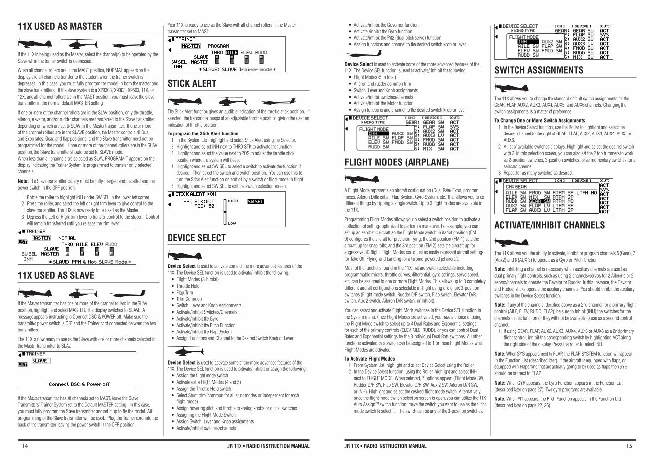
• Activate/inhibittheGovernorfunction,• Activate/inhibittheGyrofunction• Activate/inhibitthePit2(dualpitchservo)function• Assignfunctionsandchanneltothedesiredswitchknoborlever
Device Select is used to activate some of the more advanced features of the 11X. The Device SEL function is used to activate/ inhibit the following: • FlightModes(5intotal)• Aileronandruddercommontrim• Switch,LeverandKnobassignments• Activate/inhibitswitches/channels• Activate/inhibittheMotorfunction• Assignfunctionsandchanneltothedesiredswitchknoborlever
FLIGHT MODeS (AIRPLANe)
A Flight Mode represents an aircraft configuration (Dual Rate/ Expo, program mixes, Aileron Differential, Flap System, Gyro System, etc.) that allows you to do different things by flipping a single switch. Up to 3 flight modes are available in the 11X.
Programming Flight Modes allows you to select a switch position to activate a collection of settings optimized to perform a maneuver. For example, you can set up an aerobatic aircraft so the Flight Mode switch in its 1st position (FM 0) configures the aircraft for precision flying; the 2nd position (FM 1) sets the aircraft up for snap rolls; and the 3rd position (FM 2) sets the aircraft up for aggressive 3D flight. Flight Modes could just as easily represent aircraft settings for Take Off, Flying, and Landing for a turbine-powered jet aircraft.
Most of the functions found in the 11X that are switch selectable including programmable mixers, throttle curves, differential, gyro settings, servo speed, etc. can be assigned to one or more Flight Modes. This allows up to 3 completely different aircraft configurations selectable in-flight using one of six 3-position switches (Flight mode switch, Rudder D/R switch, Flap switch, Elevator D/R switch, Aux 2 switch, Aileron D/R switch, or Inhibit).
You can select and activate Flight Mode switches in the Device SEL function in the System menu. Once Flight Modes are activated, you have a choice of using the Flight Mode switch to select up to 4 Dual Rates and Exponential settings for each of the primary controls (ELEV, AILE, RUDD), or you can control Dual Rates and Exponential settings by the 3 individual Dual Rate switches. All other functions activated by a switch can be assigned to 1 or more Flight Modes when Flight Modes are activated.
To Activate flight Modes 1 From System List, highlight and select Device Select using the Roller. 2 In the Device Select function, using the Roller, highlight and select INH
next to FLIGHT MODE. When selected, 7 options appear: (Flight Mode SW, Rudder D/R SW, Flap SW, Elevator D/R SW, Aux 2 SW, Aileron D/R SW, or INH). Highlight and select the desired flight mode switch. Alternatively, once the flight mode switch selection screen is open, you can utilize the 11X Auto Assign™ switch function; move the switch you want to use as the flight mode switch to select it. The switch can be any of the 3-position switches.
SWITCH ASSIGNMENTS
The 11X allows you to change the standard default switch assignments for the GEAR, FLAP, AUX2, AUX3, AUX4, AUX5, and AUX6 channels. Changing the switch assignments is a matter of preference.
To Change One or More Switch Assignments 1 In the Device Select function, use the Roller to highlight and select the
desired channel to the right of GEAR, FLAP, AUX2, AUX3, AUX4, AUX5 or AUX6.
2 A list of available switches displays. Highlight and select the desired switch with 3. In this selection screen, you can also set the 2 top trimmers to work as 2-position switches, 3-position switches, or as momentary switches for a selected channel.
3 Repeat for as many switches as desired.
ACTIvATE/INHIbIT CHANNELS
The 11X allows you the ability to activate, inhibit or program channels 5 (Gear), 7 (Aux2) and 8 (AUX 3) to operate as a Gyro or Pitch function.
Note: Inhibiting a channel is necessary when auxiliary channels are used as dual primary flight controls, such as using 2 channels/servos for 2 Ailerons or 2 servos/channels to operate the Elevator or Rudder. In this instance, the Elevator and Rudder sticks operate the auxiliary channels. You should inhibit the auxiliary switches in the Device Select function.
Note: If any of the channels identified above as a 2nd channel for a primary flight control (AILE, ELEV, RUDD, FLAP), be sure to Inhibit (INH) the switches for the channels in this function or they will not be available to use as a second control channel.
1. If using GEAR, FLAP, AUX2, AUX3, AUX4, AUX5 or AUX6 as a 2nd primary flight control, inhibit the corresponding switch by highlighting ACT along the right side of the display. Press the roller to select INH.
Note: When SYS appears next to FLAP, the FLAP SYSTEM function will appear in the Function List (described later). If the aircraft is equipped with flaps, or equipped with Flaperons that are actually going to be used as flaps then SYS should be set next to FLAP.
Note: When GYR appears, the Gyro Function appears in the Function List (described later on page 27). Two gyro programs are available.
Note: When PIT appears, the Pitch Function appears in the Function List (described later on page 22, 26).
11X USED AS MASTER
If the 11X is being used as the Master, select the channel(s) to be operated by the Slave when the trainer switch is depressed.
When all channel rollers are in the MAST position, NORMAL appears on the display and all channels transfer to the student when the trainer switch is depressed. In this case, you must fully program the model in both the master and the slave transmitters. If the slave system is a XP9303, X9303, X9503, 11X, or 12X, and all channel rollers are in the MAST position, you must leave the slave transmitter in the normal default MASTER setting.
If one or more of the channel rollers are in the SLAV position, only the throttle, aileron, elevator, and/or rudder channels are transferred to the Slave transmitter depending on which are set to SLAV in the Master transmitter. If one or more of the channel rollers are in the SLAVE position, the Master controls all Dual and Expo rates, Gear, and flap positions, and the Slave transmitter need not be programmed for the model. If one or more of the channel rollers are in the SLAV position, the Slave transmitter should be set to SLAVE mode.When less than all channels are selected as SLAV, PROGRAM T appears on the display indicating the Trainer System is programmed to transfer only selected channels.
Note: The Slave transmitter battery must be fully charged and installed and the power switch in the OFF position.
1 Rotate the roller to highlight INH under SW SEL in the lower left corner. 2 Press the roller, and select the left or right trim lever to give control to the
slave transmitter. The 11X is now ready to be used as the Master. 3 Depress the Left or Right trim lever to transfer control to the student. Control
will remain transferred until you release the trim lever.
11X USED AS SLAvE
If the Master transmitter has one or more of the channel rollers in the SLAV position, highlight and select MASTER. The display switches to SLAVE. A message appears instructing to Connect DSC & POWER off. Make sure the transmitter power switch is OFF and the Trainer cord connected between the two transmitters.
The 11X is now ready to use as the Slave with one or more channels selected in the Master transmitter to SLAV.
If the Master transmitter has all channels set to MAST, leave the Slave Transmitters’ Trainer System set to the Default MASTER setting. In this case, you must fully program the Slave transmitter and set it up to fly the model. All programming of the Slave transmitter will be used. Plug the Trainer cord into the back of the transmitter leaving the power switch in the OFF position.
Your 11X is ready to use as the Slave with all channel rollers in the Master transmitter set to MAST.
STICK ALERT
The Stick Alert function gives an audible indication of the throttle stick position. If selected, the transmitter beeps at an adjustable throttle position giving the user an indication of throttle position.
To program the Stick Alert function1 In the System List, highlight and select Stick Alert using the Selector. 2 Highlight and select INH next to THRO STK to activate the function.3 Highlight and select the value next to POS to adjust the throttle stick
position where the system will beep.4 Highlight and select SW SEL to select a switch to activate the function if
desired. Then select the switch and switch position. You can use this to turn the Stick Alert function on and off by a switch or flight mode in flight.
5 Highlight and select SW SEL to exit the switch selection screen.
DEvICE SELECT
Device Select is used to activate some of the more advanced features of the 11X. The Device SEL function is used to activate/ inhibit the following: • FlightModes(3intotal)• ThrottleHold• FlapTrim• TrimCommon• Switch,LeverandKnobAssignments• Activate/InhibitSwitches/Channels• Activate/InhibittheGyro• Activate/InhibitthePitchFunction• Activate/InhibittheFlapSystem• AssignFunctionsandChanneltotheDesiredSwitchKnoborLever
Device Select is used to activate some of the more advanced features of the 11X. The Device SEL function is used to activate/ inhibit or assign the following: • Assigntheflightmodeswitch• ActivateextraFlightModes(4and5)• AssigntheThrottleHoldswitch• SelectStunttrim(commonforallstuntmodesorindependentforeach
flight mode) • Assignhoveringpitchandthrottletoanalogknobsordigitalswitches• AssigningtheFlightModeSwitch• AssignSwitch,LeverandKnobassignments• Activate/inhibitswitches/channels
16 JR 11X • RADIO INSTRUCTION MANUAL 17JR 11X • RADIO INSTRUCTION MANUAL
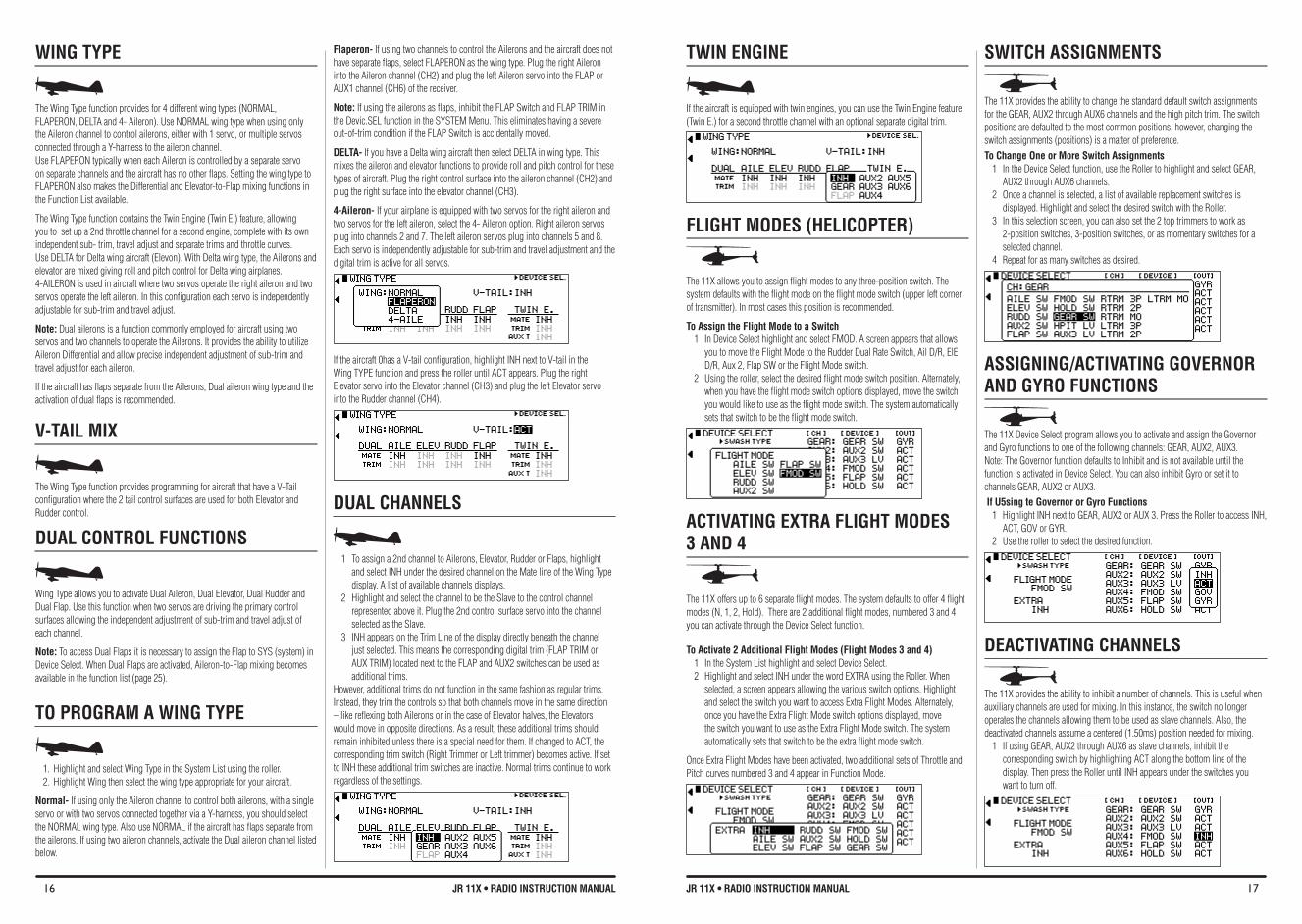
WING TYPE
The Wing Type function provides for 4 different wing types (NORMAL, FLAPERON, DELTA and 4- Aileron). Use NORMAL wing type when using only the Aileron channel to control ailerons, either with 1 servo, or multiple servos connected through a Y-harness to the aileron channel. Use FLAPERON typically when each Aileron is controlled by a separate servo on separate channels and the aircraft has no other flaps. Setting the wing type to FLAPERON also makes the Differential and Elevator-to-Flap mixing functions in the Function List available.
The Wing Type function contains the Twin Engine (Twin E.) feature, allowing you to set up a 2nd throttle channel for a second engine, complete with its own independent sub- trim, travel adjust and separate trims and throttle curves. Use DELTA for Delta wing aircraft (Elevon). With Delta wing type, the Ailerons and elevator are mixed giving roll and pitch control for Delta wing airplanes. 4-AILERON is used in aircraft where two servos operate the right aileron and two servos operate the left aileron. In this configuration each servo is independently adjustable for sub-trim and travel adjust.
Note: Dual ailerons is a function commonly employed for aircraft using two servos and two channels to operate the Ailerons. It provides the ability to utilize Aileron Differential and allow precise independent adjustment of sub-trim and travel adjust for each aileron.
If the aircraft has flaps separate from the Ailerons, Dual aileron wing type and the activation of dual flaps is recommended.
v-TAIL MIX
The Wing Type function provides programming for aircraft that have a V-Tail configuration where the 2 tail control surfaces are used for both Elevator and Rudder control.
DUAL CONTROL fUNCTIONS
Wing Type allows you to activate Dual Aileron, Dual Elevator, Dual Rudder and Dual Flap. Use this function when two servos are driving the primary control surfaces allowing the independent adjustment of sub-trim and travel adjust of each channel.
Note: To access Dual Flaps it is necessary to assign the Flap to SYS (system) in Device Select. When Dual Flaps are activated, Aileron-to-Flap mixing becomes available in the function list (page 25).
TO PROGRAM A WING TYPE
1. Highlight and select Wing Type in the System List using the roller. 2. Highlight Wing then select the wing type appropriate for your aircraft.
Normal- If using only the Aileron channel to control both ailerons, with a single servo or with two servos connected together via a Y-harness, you should select the NORMAL wing type. Also use NORMAL if the aircraft has flaps separate from the ailerons. If using two aileron channels, activate the Dual aileron channel listed below.
flaperon- If using two channels to control the Ailerons and the aircraft does not have separate flaps, select FLAPERON as the wing type. Plug the right Aileron into the Aileron channel (CH2) and plug the left Aileron servo into the FLAP or AUX1 channel (CH6) of the receiver.
Note: If using the ailerons as flaps, inhibit the FLAP Switch and FLAP TRIM in the Devic.SEL function in the SYSTEM Menu. This eliminates having a severe out-of-trim condition if the FLAP Switch is accidentally moved.
DELTA- If you have a Delta wing aircraft then select DELTA in wing type. This mixes the aileron and elevator functions to provide roll and pitch control for these types of aircraft. Plug the right control surface into the aileron channel (CH2) and plug the right surface into the elevator channel (CH3).
4-Aileron- If your airplane is equipped with two servos for the right aileron and two servos for the left aileron, select the 4- Aileron option. Right aileron servos plug into channels 2 and 7. The left aileron servos plug into channels 5 and 8. Each servo is independently adjustable for sub-trim and travel adjustment and the digital trim is active for all servos.
If the aircraft 0has a V-tail configuration, highlight INH next to V-tail in the Wing TYPE function and press the roller until ACT appears. Plug the right Elevator servo into the Elevator channel (CH3) and plug the left Elevator servo into the Rudder channel (CH4).
DUAL CHANNELS
1 To assign a 2nd channel to Ailerons, Elevator, Rudder or Flaps, highlight and select INH under the desired channel on the Mate line of the Wing Type display. A list of available channels displays.
2 Highlight and select the channel to be the Slave to the control channel represented above it. Plug the 2nd control surface servo into the channel selected as the Slave.
3 INH appears on the Trim Line of the display directly beneath the channel just selected. This means the corresponding digital trim (FLAP TRIM or AUX TRIM) located next to the FLAP and AUX2 switches can be used as additional trims.
However, additional trims do not function in the same fashion as regular trims. Instead, they trim the controls so that both channels move in the same direction – like reflexing both Ailerons or in the case of Elevator halves, the Elevators would move in opposite directions. As a result, these additional trims should remain inhibited unless there is a special need for them. If changed to ACT, the corresponding trim switch (Right Trimmer or Left trimmer) becomes active. If set to INH these additional trim switches are inactive. Normal trims continue to work regardless of the settings.
TWIN ENGINE
If the aircraft is equipped with twin engines, you can use the Twin Engine feature (Twin E.) for a second throttle channel with an optional separate digital trim.
FLIGHT MODeS (HeLICOPTeR)
The 11X allows you to assign flight modes to any three-position switch. The system defaults with the flight mode on the flight mode switch (upper left corner of transmitter). In most cases this position is recommended.
To Assign the flight Mode to a Switch 1 In Device Select highlight and select FMOD. A screen appears that allows
you to move the Flight Mode to the Rudder Dual Rate Switch, Ail D/R, ElE D/R, Aux 2, Flap SW or the Flight Mode switch.
2 Using the roller, select the desired flight mode switch position. Alternately, when you have the flight mode switch options displayed, move the switch you would like to use as the flight mode switch. The system automatically sets that switch to be the flight mode switch.
ACTIvATING EXTRA fLIGHT MODES 3 AND 4
The 11X offers up to 6 separate flight modes. The system defaults to offer 4 flight modes (N, 1, 2, Hold). There are 2 additional flight modes, numbered 3 and 4 you can activate through the Device Select function.
To Activate 2 Additional Flight Modes (Flight Modes 3 and 4) 1 In the System List highlight and select Device Select. 2 Highlight and select INH under the word EXTRA using the Roller. When
selected, a screen appears allowing the various switch options. Highlight and select the switch you want to access Extra Flight Modes. Alternately, once you have the Extra Flight Mode switch options displayed, move the switch you want to use as the Extra Flight Mode switch. The system automatically sets that switch to be the extra flight mode switch.
Once Extra Flight Modes have been activated, two additional sets of Throttle and Pitch curves numbered 3 and 4 appear in Function Mode.
SWITCH ASSIGNMENTS
The 11X provides the ability to change the standard default switch assignments for the GEAR, AUX2 through AUX6 channels and the high pitch trim. The switch positions are defaulted to the most common positions, however, changing the switch assignments (positions) is a matter of preference. To Change One or More Switch Assignments
1 In the Device Select function, use the Roller to highlight and select GEAR, AUX2 through AUX6 channels.
2 Once a channel is selected, a list of available replacement switches is displayed. Highlight and select the desired switch with the Roller.
3 In this selection screen, you can also set the 2 top trimmers to work as 2-position switches, 3-position switches, or as momentary switches for a selected channel.
4 Repeat for as many switches as desired.
ASSIGNING/ACTIvATING GOvERNOR AND GYRO fUNCTIONS
The 11X Device Select program allows you to activate and assign the Governor and Gyro functions to one of the following channels: GEAR, AUX2, AUX3. Note: The Governor function defaults to Inhibit and is not available until the function is activated in Device Select. You can also inhibit Gyro or set it to channels GEAR, AUX2 or AUX3. If U5sing te Governor or Gyro Functions
1 Highlight INH next to GEAR, AUX2 or AUX 3. Press the Roller to access INH, ACT, GOV or GYR.
2 Use the roller to select the desired function.
DEACTIvATING CHANNELS
The 11X provides the ability to inhibit a number of channels. This is useful when auxiliary channels are used for mixing. In this instance, the switch no longer operates the channels allowing them to be used as slave channels. Also, the deactivated channels assume a centered (1.50ms) position needed for mixing.
1 If using GEAR, AUX2 through AUX6 as slave channels, inhibit the corresponding switch by highlighting ACT along the bottom line of the display. Then press the Roller until INH appears under the switches you want to turn off.
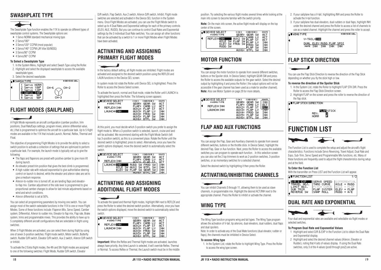
18 JR 11X • RADIO INSTRUCTION MANUAL 19JR 11X • RADIO INSTRUCTION MANUAL
SWASHPLATE TYPE
The Swashplate Type function enables the 11X to operate six different types of swashplate control systems. The Swashplate options are:• 1ServoNORMstandardmechanicalmixingtype• 2Servo/180°• 3Servo/120°CCPM(mostpopular)• 3Servo/140°CCPM(JRVibe50/90SG)• 3Servo/90°CCPM• 4Servo/90°CCPM
To Select a Swashplate Type1. In the System Menu, highlight and select Swash Type using the Roller.2. Highlight and select the displayed swashplate to access the available
swashplate types.3. Select the desired swashplate.
FLIGHT MODeS (SAILPLANe)
A Flight Mode represents an aircraft configuration (camber position, trim positions, Dual Rate/Expo settings, program mixes, aileron differential value, etc.) that is programmed to optimize the aircraft for a particular task. Up to 5 flight modes are available in the 11X that include Launch, Normal, Reflex, Thermal and Float.
The objective of programming Flight Modes is to provide the ability to select a switch position to activate a collection of settings that are optimized to perform a particular task. For example, the launch mode is typically set up to give the following: •Theflapsandflaperonsarepresetwithpositivecambertogivemorelift
during launch. •Anelevatorpresettrimpositionthatgivesthebestclimbisprogrammed.•Ahighrudderratewithreducedexponentialtogiveauthoritativesteering
control on launch is desired, while the elevator and aileron rates are set to give a medium response.
•Aileron-to-ruddermixisturnedoff,asarelandingflapsandelevator-to-flap mix. Camber adjustment of the side lever is programmed to give proportional camber changes to allow for last minute adjustments based on wind and winch conditions.
•Ailerondifferentialissetat50%.
You can select all programming parameters by moving one switch. You can assign most of the switch-selectable functions in the 11X to one or more Flight Modes. Some of these functions include: Flaperon Mix, Servo Speed, Camber system, Differential, Aileron to rudder mix, Elevator to flap mix, Flap rate, Brake system, trims and programmable mixes. This provides the ability to have up to 5 completely different aircraft configurations that are selectable in flight using switches.
When 3 Flight Modes are activated, you can select them during flight by using one of seven 3-position switches: Flight mode switch, Motor switch, Butterfly switch, Rudder D/R switch, Elevator D/R switch, Aux 2 switch, Aileron D/R switch or Inhibit.
To activate the 2 Extra flight modes, the 4th and 5th flight modes are assigned to one of the following switches: Flight Mode, Rudder D/R switch, Elevator
D/R switch, Flap Switch, Aux 2 switch, Aileron D/R switch, Inhibit. Flight mode switches are selected and activated in the Device SEL function in the System menu. Once Flight Modes are activated, you can use the Flight Mode switch to select up to 4 Dual Rates and Exponential settings for each of the primary controls (ELEV, AILE, RUDD). But you can continue to control Dual Rates and Exponential settings by the 3 individual Dual Rate switches. You can assign all other functions that can be activated by a switch to 1 or more Flight Modes when Flight Modes have been activated.
ACTIvATING AND ASSIGNING PRIMARY fLIGHT MODES
In the factory default setting, all flight modes are inhibited. Flight modes are activated and assigned to the desired switch position using the REFLEX and LAUN functions in the Device SEL screen.
In system mode list rotate the Roller until Device SEL is highlighted. Press the Roller to access the Device Select screen.
To activate the launch, normal and float mode, rotate the Roller until LAUNCH is highlighted then press the Roller. The following screen appears:
At this point, you must decide which 3-position switch you prefer to assign the flight mode to. When a 3-position switch is selected, launch, cruise and land will be activated. We recommend starting with the Flight Mode Switch (left top 3-position switch), as this is a convenient place. Rotate the Roller until the desired switch is highlighted; press to select. Alternatively, once you have the switch options displayed, move the desired switch to automatically select the switch.
ACTIvATING AND ASSIGNING ADDITIONAL fLIGHT MODES
To activate the speed and thermal flight modes, highlight INH next to REFLEX and press the Roller to select the desired switch position. Alternatively, once you have the switch options displayed, move the desired switch to automatically select the switch.
Important: When the Reflex and Thermal flight modes are activated, launches always have priority. Any time Launch is selected, it will override Reflex, Thermal or Normal. To access Reflex or Thermal, the Launch switch must be in the middle
position. Try selecting the various flight modes several times while looking at the main info screen to become familiar with the switch priority.
Note: On the main info screen, the active flight mode will display on the top center of the screen.
MOTOR fUNCTION
You can assign the motor function to operate from several different switches, buttons or the Spoiler stick. In Device Select, highlight GEAR SW and press the Roller to access the available outputs for the gear switch. Select the desired output by highlighting it and press the Roller ( the output options will not be accessible if the gear channel has been used as a mate for another channel). Note: Also see Motor System on page 29 for more details.
fLAP AND AUX fUNCTIONS
You can assign the Flap, Gear and Auxiliary channels to operate from several different switches, buttons or the throttle stick. In Device Select, highlight the desired Flap, Gear or Aux function. Next, press the Roller to access the available switches you can program to operate each function. . In this selection screen you can also set the 2 top trimmers to work as 2-position switches, 3-position switches, or as momentary switches for a selected channel.
Select the desired switch by highlighting it then press the Roller.
ACTIvATING/INHIbITING CHANNELS
You can inhibit Channels 5 through 11, allowing them to be used as slave channels, in programmable mix. Highlight the desired ACT/INH next to the appropriate channel. Press the Roller to inhibit or activate the channel.
WING TYPE
The Wing Type function programs wing and tail types. The Wing Type program allows the activation of V-tail, tip ailerons, dual elevators, dual rudders, dual flaps and dual spoilers. Note: In order to activate any of the Dual Mate functions (dual elevator, rudder or flaps), the channels must be inhibited in Device Select.
To access Wing type 1. In the System List, rotate the Roller to highlight Wing Type. Press the Roller
to access the wing type screen.
2. If your sailplane has a V-tail, highlighting INH and press the Roller to activate the V-tail function.
3. If your sailplane has dual elevators, dual rudders or dual flaps, highlight INH under the desired channel and press the Roller to access a list of channels to use as a mated channel. Highlight the channel and press the roller to accept. .
fLAP STICK DIRECTION
You can use the Flap Stick Direction to reverse the direction of the Flap Stick depending on whether you fly the stick high or low.
To reverse the direction of the Spoiler Stick1. In the System List, rotate the Roller to highlight FLAP STK DIR. Press the
Roller to access the Flap Stick Direction screen.2. Highlight FLAP on the screen and press the roller to reverse the direction of
the flap stick.
fUNCTION LIST
The Function List is used to complete the setup and adjust the aircraft’s flight characteristics. Functions include Servo Reversing, Travel Adjust, Dual Rate and Expo, Sub-Trim, Servo Speed and Programmable Mix functions, etc. Many of these functions are frequently used to adjust the flight characteristics during setup and at the field.
To Enter the function List With the transmitter on Press LIST and the Function List will appear.
DUAL RATE AND EXPONENTIAL
Four dual and exponential rates are available and selectable via flight modes or selected switches.
To Program Dual Rate and Exponential values 1 Highlight and select D/R & EXP in the Function List to obtain the Dual Rate
and Exponential display. 2 Highlight and select the desired channel values (Aileron, Elevator or
Rudder), noting that 4 sets of values display. If using the Dual Rate switches, only 3 of the 4 values (pos0 through pos2) are active.
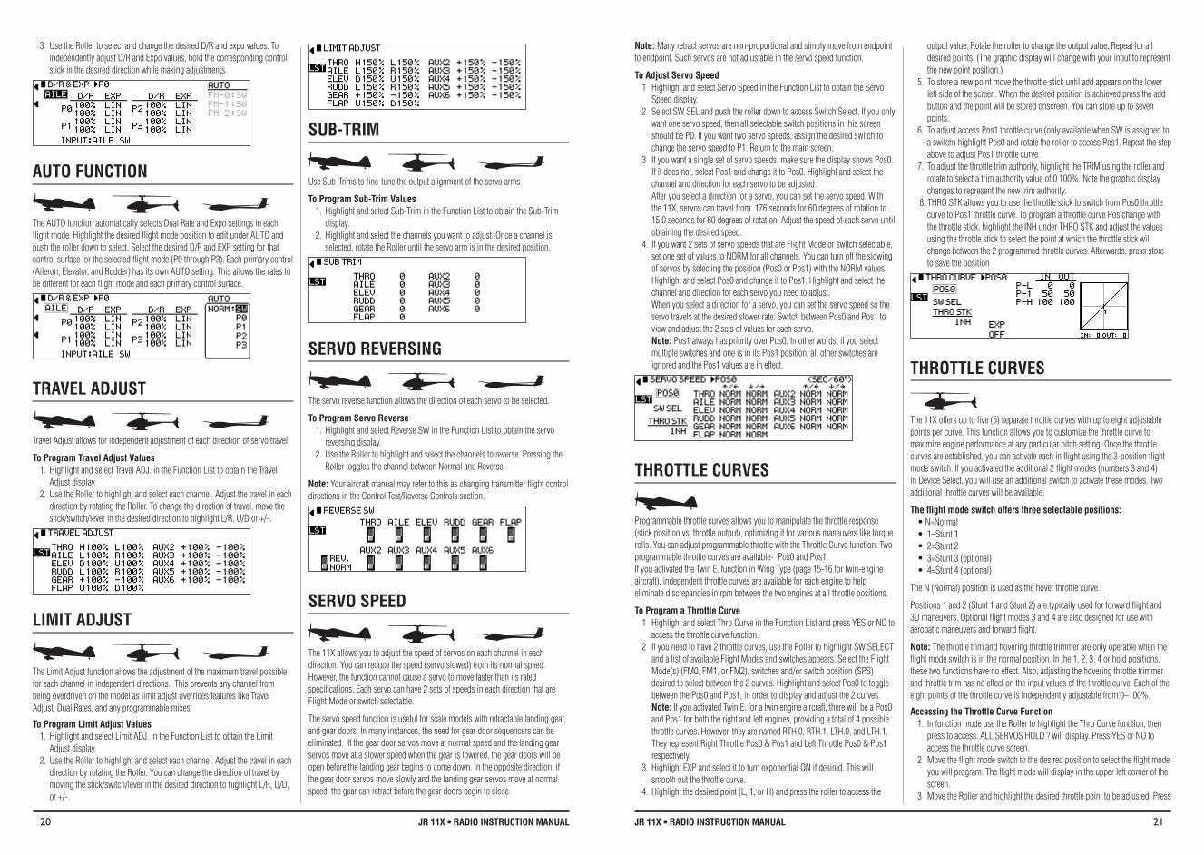
20 JR 11X • RADIO INSTRUCTION MANUAL 21JR 11X • RADIO INSTRUCTION MANUAL
Note: Many retract servos are non-proportional and simply move from endpoint to endpoint. Such servos are not adjustable in the servo speed function.
To Adjust Servo Speed 1 Highlight and select Servo Speed in the Function List to obtain the Servo
Speed display. 2 Select SW SEL and push the roller down to access Switch Select. If you only
want one servo speed, then all selectable switch positions in this screen should be P0. If you want two servo speeds, assign the desired switch to change the servo speed to P1. Return to the main screen.
3 If you want a single set of servo speeds, make sure the display shows Pos0. If it does not, select Pos1 and change it to Pos0. Highlight and select the channel and direction for each servo to be adjusted. After you select a direction for a servo, you can set the servo speed. With the 11X, servos can travel from .176 seconds for 60 degrees of rotation to 15.0 seconds for 60 degrees of rotation. Adjust the speed of each servo until obtaining the desired speed.
4. If you want 2 sets of servo speeds that are Flight Mode or switch selectable, set one set of values to NORM for all channels. You can turn off the slowing of servos by selecting the position (Pos0 or Pos1) with the NORM values. Highlight and select Pos0 and change it to Pos1. Highlight and select the channel and direction for each servo you need to adjust. When you select a direction for a servo, you can set the servo speed so the servo travels at the desired slower rate. Switch between Pos0 and Pos1 to view and adjust the 2 sets of values for each servo. Note: Pos1 always has priority over Pos0. In other words, if you select multiple switches and one is in its Pos1 position, all other switches are ignored and the Pos1 values are in effect.
THROTTLE CURvES
Programmable throttle curves allows you to manipulate the throttle response (stick position vs. throttle output), optimizing it for various maneuvers like torque rolls. You can adjust programmable throttle with the Throttle Curve function. Two programmable throttle curves are available- Pos0 and Pos1. If you activated the Twin E. function in Wing Type (page 15-16 for twin-engine aircraft), independent throttle curves are available for each engine to help eliminate discrepancies in rpm between the two engines at all throttle positions.
To Program a Throttle Curve 1 Highlight and select Thro Curve in the Function List and press YES or NO to
access the throttle curve function. 2 If you need to have 2 throttle curves, use the Roller to highlight SW SELECT
and a list of available Flight Modes and switches appears. Select the Flight Mode(s) (FM0, FM1, or FM2), switches and/or switch position (SPS) desired to select between the 2 curves. Highlight and select Pos0 to toggle between the Pos0 and Pos1, in order to display and adjust the 2 curves. Note: If you activated Twin E. for a twin engine aircraft, there will be a Pos0 and Pos1 for both the right and left engines, providing a total of 4 possible throttle curves. However, they are named RTH.0, RTH.1, LTH.0, and LTH.1. They represent Right Throttle Pos0 & Pos1 and Left Throttle Pos0 & Pos1 respectively.
3. Highlight EXP and select it to turn exponential ON if desired. This will smooth out the throttle curve.
4. Highlight the desired point (L, 1, or H) and press the roller to access the
output value. Rotate the roller to change the output value. Repeat for all desired points. (The graphic display will change with your input to represent the new point position.)
5. To store a new point move the throttle stick until add appears on the lower left side of the screen. When the desired position is achieved press the add button and the point will be stored onscreen. You can store up to seven points.
6. To adjust access Pos1 throttle curve (only available when SW is assigned to a switch) highlight Pos0 and rotate the roller to access Pos1. Repeat the step above to adjust Pos1 throttle curve.
7. To adjust the throttle trim authority, highlight the TRIM using the roller and rotate to select a trim authority value of 0 100%. Note the graphic display changes to represent the new trim authority.
8. THRO STK allows you to use the throttle stick to switch from Pos0 throttle curve to Pos1 throttle curve. To program a throttle curve Pos change with the throttle stick, highlight the INH under THRO STK and adjust the values using the throttle stick to select the point at which the throttle stick will change between the 2 programmed throttle curves. Afterwards, press store to save the position
THROTTLE CURvES
The 11X offers up to five (5) separate throttle curves with up to eight adjustable points per curve. This function allows you to customize the throttle curve to maximize engine performance at any particular pitch setting. Once the throttle curves are established, you can activate each in flight using the 3-position flight mode switch. If you activated the additional 2 flight modes (numbers 3 and 4) in Device Select, you will use an additional switch to activate these modes. Two additional throttle curves will be available.
The flight mode switch offers three selectable positions: •N=Normal• 1=Stunt1• 2=Stunt2• 3=Stunt3(optional)• 4=Stunt4(optional)
The N (Normal) position is used as the hover throttle curve.
Positions 1 and 2 (Stunt 1 and Stunt 2) are typically used for forward flight and 3D maneuvers. Optional flight modes 3 and 4 are also designed for use with aerobatic maneuvers and forward flight.
Note: The throttle trim and hovering throttle trimmer are only operable when the flight mode switch is in the normal position. In the 1, 2, 3, 4 or hold positions, these two functions have no effect. Also, adjusting the hovering throttle trimmer and throttle trim has no effect on the input values of the throttle curve. Each of the eight points of the throttle curve is independently adjustable from 0–100%.
Accessing the Throttle Curve function 1. In function mode use the Roller to highlight the Thro Curve function, then
press to access. ALL SERVOS HOLD ? will display. Press YES or NO to access the throttle curve screen.
2 Move the flight mode switch to the desired position to select the flight mode you will program. The flight mode will display in the upper left corner of the screen.
3 Move the Roller and highlight the desired throttle point to be adjusted. Press
3 Use the Roller to select and change the desired D/R and expo values. To independently adjust D/R and Expo values, hold the corresponding control stick in the desired direction while making adjustments.
AUTO fUNCTION
The AUTO function automatically selects Dual Rate and Expo settings in each flight mode. Highlight the desired flight mode position to edit under AUTO and push the roller down to select. Select the desired D/R and EXP setting for that control surface for the selected flight mode (P0 through P3). Each primary control (Aileron, Elevator, and Rudder) has its own AUTO setting. This allows the rates to be different for each flight mode and each primary control surface.
TRAvEL ADJUST
Travel Adjust allows for independent adjustment of each direction of servo travel.
To Program Travel Adjust values1. Highlight and select Travel ADJ. in the Function List to obtain the Travel
Adjust display.2. Use the Roller to highlight and select each channel. Adjust the travel in each
direction by rotating the Roller. To change the direction of travel, move the stick/switch/lever in the desired direction to highlight L/R, U/D or +/-.
LIMIT ADJUST
The Limit Adjust function allows the adjustment of the maximum travel possible for each channel in independent directions. This prevents any channel from being overdriven on the model as limit adjust overrides features like Travel Adjust, Dual Rates, and any programmable mixes.
To Program Limit Adjust values1. Highlight and select Limit ADJ. in the Function List to obtain the Limit
Adjust display.2. Use the Roller to highlight and select each channel. Adjust the travel in each
direction by rotating the Roller. You can change the direction of travel by moving the stick/switch/lever in the desired direction to highlight L/R, U/D, or +/-.
SUb-TRIM
Use Sub-Trims to fine-tune the output alignment of the servo arms.
To Program Sub-Trim Values 1. Highlight and select Sub-Trim in the Function List to obtain the Sub-Trim
display.2. Highlight and select the channels you want to adjust. Once a channel is
selected, rotate the Roller until the servo arm is in the desired position.
SERvO REvERSING
The servo reverse function allows the direction of each servo to be selected.
To Program Servo Reverse 1. Highlight and select Reverse SW in the Function List to obtain the servo
reversing display.2. Use the Roller to highlight and select the channels to reverse. Pressing the
Roller toggles the channel between Normal and Reverse.
Note: Your aircraft manual may refer to this as changing transmitter flight control directions in the Control Test/Reverse Controls section.
SERvO SPEED
The 11X allows you to adjust the speed of servos on each channel in each direction. You can reduce the speed (servo slowed) from its normal speed. However, the function cannot cause a servo to move faster than its rated specifications. Each servo can have 2 sets of speeds in each direction that are Flight Mode or switch selectable.
The servo speed function is useful for scale models with retractable landing gear and gear doors. In many instances, the need for gear door sequencers can be eliminated. If the gear door servos move at normal speed and the landing gear servos move at a slower speed when the gear is lowered, the gear doors will be open before the landing gear begins to come down. In the opposite direction, if the gear door servos move slowly and the landing gear servos move at normal speed, the gear can retract before the gear doors begin to close.
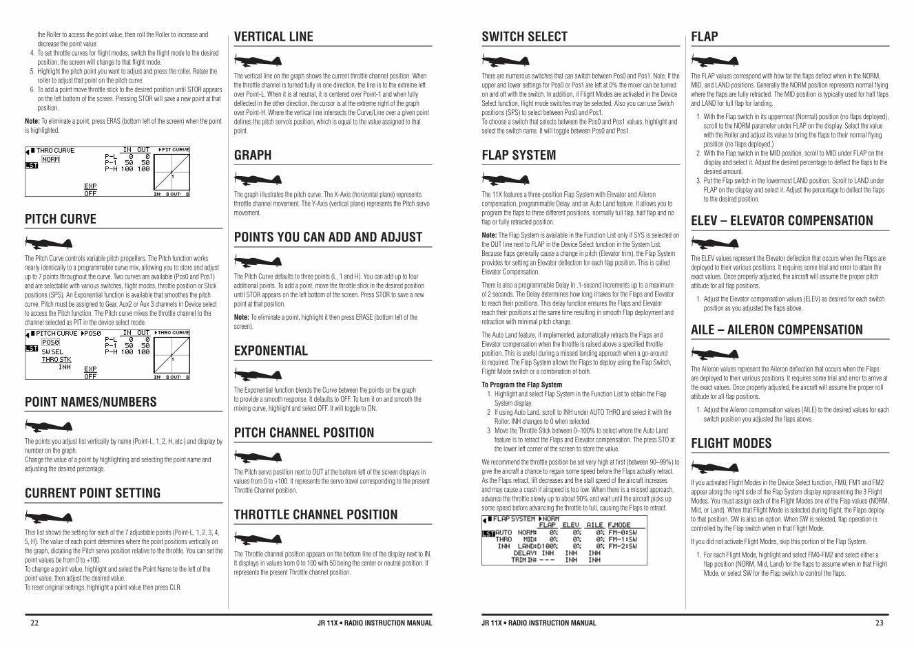
22 JR 11X • RADIO INSTRUCTION MANUAL 23JR 11X • RADIO INSTRUCTION MANUAL
the Roller to access the point value, then roll the Roller to increase and decrease the point value.
4. To set throttle curves for flight modes, switch the flight mode to the desired position; the screen will change to that flight mode.
5. Highlight the pitch point you want to adjust and press the roller. Rotate the roller to adjust that point on the pitch curve.
6. To add a point move throttle stick to the desired position until STOR appears on the left bottom of the screen. Pressing STOR will save a new point at that position.
Note: To eliminate a point, press ERAS (bottom left of the screen) when the point is highlighted.
PITCH CURvE
The Pitch Curve controls variable pitch propellers. The Pitch function works nearly identically to a programmable curve mix, allowing you to store and adjust up to 7 points throughout the curve. Two curves are available (Pos0 and Pos1) and are selectable with various switches, flight modes, throttle position or Stick positions (SPS). An Exponential function is available that smoothes the pitch curve. Pitch must be assigned to Gear, Aux2 or Aux 3 channels in Device select to access the Pitch function. The Pitch curve mixes the throttle channel to the channel selected as PIT in the device select mode.
POINT NAMES/NUMbERS
The points you adjust list vertically by name (Point-L, 1, 2, H, etc.) and display by number on the graph. Change the value of a point by highlighting and selecting the point name and adjusting the desired percentage.
CURRENT POINT SETTING
This list shows the setting for each of the 7 adjustable points (Point-L, 1, 2, 3, 4, 5, H). The value of each point determines where the point positions vertically on the graph, dictating the Pitch servo position relative to the throttle. You can set the point values be from 0 to +100. To change a point value, highlight and select the Point Name to the left of the point value, then adjust the desired value. To reset original settings, highlight a point value then press CLR.
vERTICAL LINE
The vertical line on the graph shows the current throttle channel position. When the throttle channel is turned fully in one direction, the line is to the extreme left over Point-L. When it is at neutral, it is centered over Point-1 and when fully deflected in the other direction, the cursor is at the extreme right of the graph over Point-H. Where the vertical line intersects the Curve/Line over a given point defines the pitch servo’s position, which is equal to the value assigned to that point.
GRAPH
The graph illustrates the pitch curve. The X-Axis (horizontal plane) represents throttle channel movement. The Y-Axis (vertical plane) represents the Pitch servo movement.
POINTS YOU CAN ADD AND ADJUST
The Pitch Curve defaults to three points (L, 1 and H). You can add up to four additional points. To add a point, move the throttle stick in the desired position until STOR appears on the left bottom of the screen. Press STOR to save a new point at that position.
Note: To eliminate a point, highlight it then press ERASE (bottom left of the screen).
EXPONENTIAL
The Exponential function blends the Curve between the points on the graph to provide a smooth response. It defaults to OFF. To turn it on and smooth the mixing curve, highlight and select OFF. It will toggle to ON.
PITCH CHANNEL POSITION
The Pitch servo position next to OUT at the bottom left of the screen displays in values from 0 to +100. It represents the servo travel corresponding to the present Throttle Channel position.
THROTTLE CHANNEL POSITION
The Throttle channel position appears on the bottom line of the display next to IN. It displays in values from 0 to 100 with 50 being the center or neutral position. It represents the present Throttle channel position.
SWITCH SELECT
There are numerous switches that can switch between Pos0 and Pos1. Note: If the upper and lower settings for Pos0 or Pos1 are left at 0% the mixer can be turned on and off with the switch. In addition, if Flight Modes are activated in the Device Select function, flight mode switches may be selected. Also you can use Switch positions (SPS) to select between Pos0 and Pos1.To choose a switch that selects between the Pos0 and Pos1 values, highlight and select the switch name. It will toggle between Pos0 and Pos1.
fLAP SYSTEM
The 11X features a three-position Flap System with Elevator and Aileron compensation, programmable Delay, and an Auto Land feature. It allows you to program the flaps to three different positions, normally full flap, half flap and no flap or fully retracted position.
Note: The Flap System is available in the Function List only if SYS is selected on the OUT line next to FLAP in the Device Select function in the System List. Because flaps generally cause a change in pitch (Elevator trim), the Flap System provides for setting an Elevator deflection for each flap position. This is called Elevator Compensation.
There is also a programmable Delay in .1-second increments up to a maximum of 2 seconds. The Delay determines how long it takes for the Flaps and Elevator to reach their positions. This delay function ensures the Flaps and Elevator reach their positions at the same time resulting in smooth Flap deployment and retraction with minimal pitch change.
The Auto Land feature, if implemented, automatically retracts the Flaps and Elevator compensation when the throttle is raised above a specified throttle position. This is useful during a missed landing approach when a go-around is required. The Flap System allows the Flaps to deploy using the Flap Switch, Flight Mode switch or a combination of both.
To Program the flap System 1. Highlight and select Flap System in the Function List to obtain the Flap
System display. 2 If using Auto Land, scroll to INH under AUTO THRO and select it with the
Roller. INH changes to 0 when selected.3 Move the Throttle Stick between 0–100% to select where the Auto Land
feature is to retract the Flaps and Elevator compensation. The press STO at the lower left corner of the screen to store the value.
We recommend the throttle position be set very high at first (between 90–99%) to give the aircraft a chance to regain some speed before the Flaps actually retract. As the Flaps retract, lift decreases and the stall speed of the aircraft increases and may cause a crash if airspeed is too low. When there is a missed approach, advance the throttle slowly up to about 90% and wait until the aircraft picks up some speed before advancing the throttle to full, causing the Flaps to retract.
fLAP
The FLAP values correspond with how far the flaps deflect when in the NORM, MID, and LAND positions. Generally the NORM position represents normal flying where the flaps are fully retracted. The MID position is typically used for half flaps and LAND for full flap for landing.
1. With the Flap switch in its uppermost (Normal) position (no flaps deployed), scroll to the NORM parameter under FLAP on the display. Select the value with the Roller and adjust its value to bring the flaps to their normal flying position (no flaps deployed.)
2. With the Flap switch in the MID position, scroll to MID under FLAP on the display and select it. Adjust the desired percentage to deflect the flaps to the desired amount.
3. Put the Flap switch in the lowermost LAND position. Scroll to LAND under FLAP on the display and select it. Adjust the percentage to deflect the flaps to the desired position.
eLeV – eLeVATOR COMPeNSATION
The ELEV values represent the Elevator deflection that occurs when the Flaps are deployed to their various positions. It requires some trial and error to attain the exact values. Once properly adjusted, the aircraft will assume the proper pitch attitude for all flap positions.
1. Adjust the Elevator compensation values (ELEV) as desired for each switch position as you adjusted the flaps above.
AILe – AILeRON COMPeNSATION
The Aileron values represent the Aileron deflection that occurs when the Flaps are deployed to their various positions. It requires some trial and error to arrive at the exact values. Once properly adjusted, the aircraft will assume the proper roll attitude for all flap positions.
1. Adjust the Aileron compensation values (AILE) to the desired values for each switch position you adjusted the flaps above.
fLIGHT MODES
If you activated Flight Modes in the Device Select function, FM0, FM1 and FM2 appear along the right side of the Flap System display representing the 3 Flight Modes. You must assign each of the Flight Modes one of the Flap values (NORM, Mid, or Land). When that Flight Mode is selected during flight, the Flaps deploy to that position. SW is also an option. When SW is selected, flap operation is controlled by the Flap switch when in that Flight Mode.
If you did not activate Flight Modes, skip this portion of the Flap System.
1. For each Flight Mode, highlight and select FM0-FM2 and select either a flap position (NORM, Mid, Land) for the flaps to assume when in that Flight Mode, or select SW for the Flap switch to control the flaps.
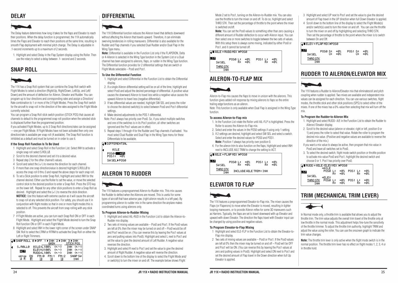
24 JR 11X • RADIO INSTRUCTION MANUAL 25JR 11X • RADIO INSTRUCTION MANUAL
DELAY
The Delay feature determines how long it takes for the flaps and Elevator to reach their positions. When the delay function is programmed, the 11X automatically times the Flaps and Elevator to reach their positions at the same time, resulting in smooth Flap deployment with minimal pitch change. The Delay is adjustable in .1-second increments up to a maximum of 2 seconds.
1. Highlight and select Delay in the Flap System display using the Roller. Then use the rotary to select a delay between .1- second and 2 seconds.
SNAP ROLL
The 11X has a Snap Roll system that can combine the Snap Roll switch with Flight Modes to select a direction (Right/Up, Right/Down, Left/Up, and Left/Down) and the amount of deflection for Aileron, Elevator and Rudder. You can program up to four directions and corresponding rates and assign a Direction/Rate combination to 1 or more of the 3 Flight Modes. Press the Snap Roll switch for the aircraft to snap roll in the direction of the rates assigned to the Flight Mode currently selected. You can program a Snap Roll stick switch position (STICK POS) that causes all channels to default to the programmed snap roll position when the selected stick is displaced further than the programmed position. If you activated Flight Modes, up to 3 Snap Roll directions/rates can be assigned —oneperFlightMode.IfFlightModeshavenotbeenactivatedthenonlyonedirection/rate is available per snap roll (4 available). The Snap Roll function is inhibited as a default and must be turned on in order to use it.
If the Snap Roll function Is To be Used 1 Highlight and select Snap Roll in the Function List. Select INH to activate a
single snap roll select S.ROLLØ.2 Scroll to the desired channel and set it to a desired value. 3 Repeat step 2 for the other channel’s values.4 Scroll and select the (+/-) to reverse the direction for each channel. 5 If more than one snap direction/value is desired highlight S.ROLLØ to
access the snap roll 0 thru 3 and repeat the above steps for each snap roll.6 To set a Stick position to enter Snap Roll, highlight and select INH for the
channel desired. Either use the Roller to set the value, or move the selected control stick to the desired position to enter a Snap Roll. Press the STO key on the lower left. Repeat for any other stick positions to enter a Snap Roll as desired. Highlight and select the (+/-) to reverse the stick direction. NOTICE: Use this feature with extreme caution as it will cause the aircraft to snap roll at any selected stick position. For safety, you should use it in conjunction with flight modes so that in one or more flight modes this is selected to off. This prevents the aircraft from snap rolling with any stick position.
7 If Flight Modes are active, you can turn each Snap Roll ON or OFF in each Flight Mode. Highlight and select the Flight Mode desired to turn the Snap Roll function ON or OFF in each Flight Mode.
8 Highlight and select INH in the lower right corner of the screen under SNAP SW. Roll to select the LTRM or RTRM to activate the Snap Roll on either the Left or Right Trimmers.
DIffERENTIAL
The 11X Differential function reduces the Aileron travel that deflects downward without affecting the Aileron that travels upward. Therefore, it can eliminate swerving tendencies in rolling maneuvers. Differential is also available for the Rudder and Flap channels if you selected Dual Rudder and/or Dual Flap in the Wing Type menu.Note: Differential is available in the Function List only if the FLAPERON, Delta or 4-Aileron is selected in the Wing Type function in the System List or a Dual channel has been assigned to ailerons, flaps, or rudder in the Wing Type function. The Differential function provides for 2 differential settings that are switch or Flight Mode selectable – Pos0 and Pos1.
To Use the Differential function 1. Highlight and select Differential in the Function List to obtain the Differential
display. 2. If a single Aileron differential setting will be on all of the time, highlight and
select Pos0 and adjust the desired percentage of differential. A positive value causes the downward Aileron to travel less while a negative value causes the upward Aileron to travel less (negative differential).
3 If two differential values are needed, highlight SW SEL and press the roller to choose the desired switch(s) to select between Pos0 and Pos1 differential settings.
4 Make desired adjustments to the POS 1 differential. Note: Pos1 always has priority over Pos0. So, if you select multiple switches
and one of the switches is in its Pos1 position, all other switches are ignored and the Pos1 values are in effect.
5 Repeat steps 1 through 4 for the Rudder and Flap channels if activated. You must select Dual Rudder and Dual Flap in the Wing Type menu for these Differentials to be available.
AILERON TO RUDDER
The 11X features a preprogrammed Aileron-to-Rudder mix. This mix causes the Rudder to deflect when the Ailerons are moved. This is useful for some types of aircraft that have adverse yaw, (right aileron results in a left yaw). By programming aileron to rudder mix in the same direction the airplane makes coordinated turns using ailerons only.
To Program Aileron-to-Rudder Mixing 1 Highlight and select AIL-RUD in the Function List to obtain the Aileron-to-
Rudder mix display. 2 Two sets of mixing values are available – Pos0 and Pos1. If the Pos0 values
are left at 0% then the mixer may be turned on and off – Pos0 would be off and Pos1 would be on. (You can reverse this by leaving the Pos1 values at zero and putting values into Pos0). Highlight and select L next to Pos1 and set the value to give the desired amount of Left Rudder. A negative value reverses the direction.
3. Highlight and select R next to Pos1 and set the value to give the desired amount of Right Rudder. A negative value will reverse the direction.
4. Scroll down to the bottom line of the display to select the Flight Mode and/or switch(s) to turn the mixer on and off. The example below shows Flight
Mode 2 set to Pos1, turning on the Aileron-to-Rudder mix. You can also use the throttle to turn the mixer on and off. To do so, highlight and select THRO STK. Then set the percentage of throttle to the point where the mixer is switched on/off. Note: You can set the Pos0 values to something other than zero causing a different amount of Rudder deflection to occur with Aileron input. You can then select one or more switches to toggle between the two sets of values. With this setup there is always some mixing, indicated by either Pos0 or Pos1, and it cannot be turned off.
AILERON-TO-fLAP MIX
Aileron-to-Flap mix causes the flaps to move in unison with the ailerons. This function gives added roll response by mixing ailerons to flaps so the entire trailing edge functions as an aileron. Note: This function is only available when Dual Flap is assigned in the Wing Type function.
To access Aileron-to-flap mix1. In the Function List rotate the Roller until AIL-FLP is highlighted. Press the
Roller to access the Aileron-to-Flap mix. 2. Select and enter the values in the POS0 settings if using only 1 setting. 3. If 2 settings are desired, highlight and select SW SEL and select a switch.
Select and enter the desired values for POS0 and POS1. Note: Position 1 always has priority over position 0.
4. For the aileron trim to also function on the flaps, highlight and select INH next to INCLUDE AILE TRIM to change the setting to ACT.
ELEvATOR TO fLAP
The 11X features a preprogrammed Elevator-to-Flap mix. The mixer causes the Flaps (or Flaperons) to move when the Elevator is moved, resulting in tighter looping maneuvers, or to provide Aileron reflex for some 3D maneuvers such as Harriers. Typically, the flaps are set to travel downward with up Elevator and upward with down Elevator. The direction the flaps travel with Elevator input can be changed by using positive and negative values.
To Program Elevator-to-flap Mixing 1 Highlight and select ELE-FLP in the Function List to obtain the Elevator-to-
Flap mix display. 2 Two sets of mixing values are available – Pos0 or Pos1. If the Pos0 values
are left at 0% then the mixer may be turned on and off – Pos0 will be OFF and Pos1 will be ON. (You can reverse this by leaving the Pos1 values at zero and putting values in Pos0). Highlight and select DN next to Pos1 and set the desired amount of Flap travel in the Down direction when full Up Elevator is applied.
3 Highlight and select UP next to Pos1 and set the value to give the desired amount of Flap travel in the UP direction when full Down Elevator is applied.
4 Scroll down to the bottom line of the display to select the Flight Mode(s) and/or switch(s) used to turn the mixer on and off. You can use the throttle to turn the mixer on and off by highlighting and selecting THRO STK. Then set the percentage of throttle to the point where the mixer is to switch between On and Off.
RUDDER TO AILERON/ELEvATOR MIX
The 11X features a Rudder to Aileron/Elevator mix that eliminatesroll and pitch coupling when rudder is applied. Two mixes are available and independent mix values can be assigned for each direction. You can use various switches, flight modes, the throttle stick and other stick positions (SPS) to select either of the mixes. If one of the mixes has a 0% value then selecting that mix will turn off the mix.
To Program the Rudder-to-Aileron Mix 1. Highlight and select RUDD- A/E in the Function List to obtain the Rudder to
Aileron/ Elevator display. 2. Scroll to the desired value (aileron or elevator, right or left, position 0 or
1) and press the roller to select that value. Rotate the roller to program the desired mix value. (Positive and negative values are available to reverse the direction of the mix.)
If you want a mix value to always be active, then program that mix value in Pos0 and leave all switches set to Pos0.
3. To select the desired switch, flight mode switch position or throttle position to activate mix value Pos0 and Pos1, highlight the desired switch and choose 0 or 1. Pos1 has priority over Pos0.
TRIM (MeCHANICAL TRIM LeVeR)
In Normal mode only, a throttle trim is available that allows you to adjust the throttle trim. The trim value adjusts the overall trim travel of the throttle only at low throttle in the normal mode. This adjustment helps fine-tune the sensitivity of the throttle trimmer. To adjust the throttle trim authority, highlight TRIM and adjust the value using the roller. You can use the onscreen graph to indicate the trim value changes.
Note: The throttle trim lever is only active when the flight mode switch is in the normal position. The throttle trim lever has no effect on flight modes 1, 2, 3, 4 or in throttle hold.
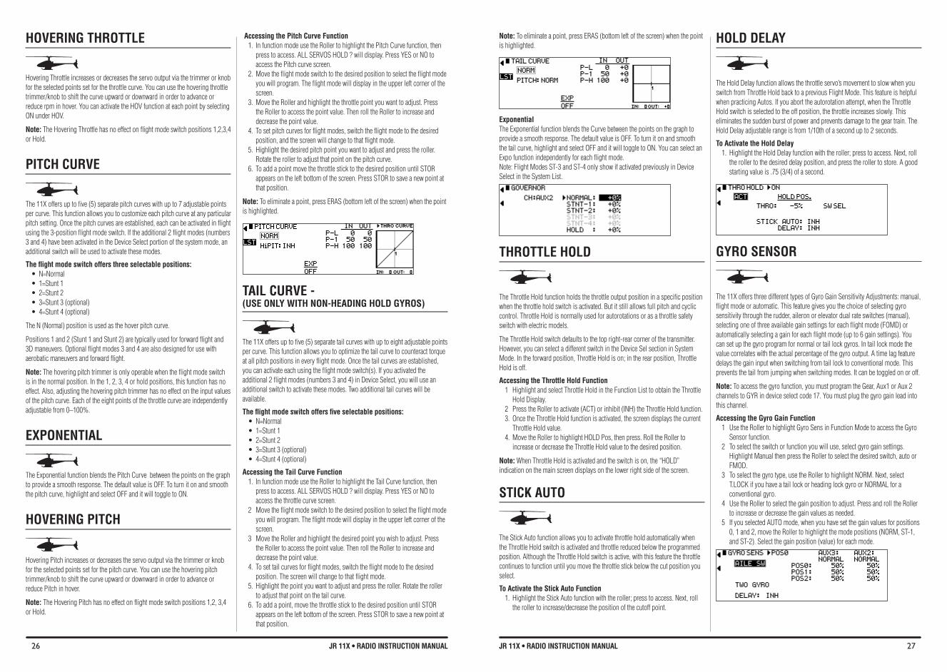
26 JR 11X • RADIO INSTRUCTION MANUAL 27JR 11X • RADIO INSTRUCTION MANUAL
HOvERING THROTTLE
Hovering Throttle increases or decreases the servo output via the trimmer or knob for the selected points set for the throttle curve. You can use the hovering throttle trimmer/knob to shift the curve upward or downward in order to advance or reduce rpm in hover. You can activate the HOV function at each point by selecting ON under HOV.
Note: The Hovering Throttle has no effect on flight mode switch positions 1,2,3,4 or Hold.
PITCH CURvE
The 11X offers up to five (5) separate pitch curves with up to 7 adjustable points per curve. This function allows you to customize each pitch curve at any particular pitch setting. Once the pitch curves are established, each can be activated in flight using the 3-position flight mode switch. If the additional 2 flight modes (numbers 3 and 4) have been activated in the Device Select portion of the system mode, an additional switch will be used to activate these modes.
The flight mode switch offers three selectable positions: • N=Normal• 1=Stunt1• 2=Stunt2• 3=Stunt3(optional)• 4=Stunt4(optional)
The N (Normal) position is used as the hover pitch curve.
Positions 1 and 2 (Stunt 1 and Stunt 2) are typically used for forward flight and 3D maneuvers. Optional flight modes 3 and 4 are also designed for use with aerobatic maneuvers and forward flight.
Note: The hovering pitch trimmer is only operable when the flight mode switch is in the normal position. In the 1, 2, 3, 4 or hold positions, this function has no effect. Also, adjusting the hovering pitch trimmer has no effect on the input values of the pitch curve. Each of the eight points of the throttle curve are independently adjustable from 0–100%.
EXPONENTIAL
The Exponential function blends the Pitch Curve between the points on the graph to provide a smooth response. The default value is OFF. To turn it on and smooth the pitch curve, highlight and select OFF and it will toggle to ON.
HOvERING PITCH
Hovering Pitch increases or decreases the servo output via the trimmer or knob for the selected points set for the pitch curve. You can use the hovering pitch trimmer/knob to shift the curve upward or downward in order to advance or reduce Pitch in hover.
Note: The Hovering Pitch has no effect on flight mode switch positions 1,2, 3,4 or Hold.
Accessing the Pitch Curve function1. In function mode use the Roller to highlight the Pitch Curve function, then
press to access. ALL SERVOS HOLD ? will display. Press YES or NO to access the Pitch curve screen.
2. Move the flight mode switch to the desired position to select the flight mode you will program. The flight mode will display in the upper left corner of the screen.
3. Move the Roller and highlight the throttle point you want to adjust. Press the Roller to access the point value. Then roll the Roller to increase and decrease the point value.
4. To set pitch curves for flight modes, switch the flight mode to the desired position, and the screen will change to that flight mode.
5. Highlight the desired pitch point you want to adjust and press the roller. Rotate the roller to adjust that point on the pitch curve.
6. To add a point move the throttle stick to the desired position until STOR appears on the left bottom of the screen. Press STOR to save a new point at that position.
Note: To eliminate a point, press ERAS (bottom left of the screen) when the point is highlighted.
TAIL CURvE - (USe ONLy WITH NON-HeADING HOLD GyROS)
The 11X offers up to five (5) separate tail curves with up to eight adjustable points per curve. This function allows you to optimize the tail curve to counteract torque at all pitch positions in every flight mode. Once the tail curves are established, you can activate each using the flight mode switch(s). If you activated the additional 2 flight modes (numbers 3 and 4) in Device Select, you will use an additional switch to activate these modes. Two additional tail curves will be available.
The flight mode switch offers five selectable positions: • N=Normal• 1=Stunt1• 2=Stunt2• 3=Stunt3(optional)• 4=Stunt4(optional)
Accessing the Tail Curve function 1. In function mode use the Roller to highlight the Tail Curve function, then
press to access. ALL SERVOS HOLD ? will display. Press YES or NO to access the throttle curve screen.
2 Move the flight mode switch to the desired position to select the flight mode you will program. The flight mode will display in the upper left corner of the screen.
3 Move the Roller and highlight the desired point you wish to adjust. Press the Roller to access the point value. Then roll the Roller to increase and decrease the point value.
4. To set tail curves for flight modes, switch the flight mode to the desired position. The screen will change to that flight mode.
5. Highlight the point you want to adjust and press the roller. Rotate the roller to adjust that point on the tail curve.
6. To add a point, move the throttle stick to the desired position until STOR appears on the left bottom of the screen. Press STOR to save a new point at that position.
Note: To eliminate a point, press ERAS (bottom left of the screen) when the point is highlighted.
Exponential The Exponential function blends the Curve between the points on the graph to provide a smooth response. The default value is OFF. To turn it on and smooth the tail curve, highlight and select OFF and it will toggle to ON. You can select an Expo function independently for each flight mode. Note: Flight Modes ST-3 and ST-4 only show if activated previously in Device Select in the System List.
THROTTLE HOLD
The Throttle Hold function holds the throttle output position in a specific position when the throttle hold switch is activated. But it still allows full pitch and cyclic control. Throttle Hold is normally used for autorotations or as a throttle safety switch with electric models.
The Throttle Hold switch defaults to the top right-rear corner of the transmitter. However, you can select a different switch in the Device Sel section in System Mode. In the forward position, Throttle Hold is on; in the rear position, Throttle Hold is off.
Accessing the Throttle Hold function 1 Highlight and select Throttle Hold in the Function List to obtain the Throttle
Hold Display. 2 Press the Roller to activate (ACT) or inhibit (INH) the Throttle Hold function. 3. Once the Throttle Hold function is activated, the screen displays the current
Throttle Hold value. 4. Move the Roller to highlight HOLD Pos, then press. Roll the Roller to
increase or decrease the Throttle Hold value to the desired position.
Note: When Throttle Hold is activated and the switch is on, the “HOLD” indication on the main screen displays on the lower right side of the screen.
STICK AUTO
The Stick Auto function allows you to activate throttle hold automatically when the Throttle Hold switch is activated and throttle reduced below the programmed position. Although the Throttle Hold switch is active, with this feature the throttle continues to function until you move the throttle stick below the cut position you select.
To Activate the Stick Auto Function 1. Highlight the Stick Auto function with the roller; press to access. Next, roll
the roller to increase/decrease the position of the cutoff point.
HOLD DELAY
The Hold Delay function allows the throttle servo’s movement to slow when you switch from Throttle Hold back to a previous Flight Mode. This feature is helpful when practicing Autos. If you abort the autorotation attempt, when the Throttle Hold switch is selected to the off position, the throttle increases slowly. This eliminates the sudden burst of power and prevents damage to the gear train. The Hold Delay adjustable range is from 1/10th of a second up to 2 seconds.
To Activate the Hold Delay 1. Highlight the Hold Delay function with the roller; press to access. Next, roll
the roller to the desired delay position, and press the roller to store. A good starting value is .75 (3/4) of a second.
GYRO SENSOR
The 11X offers three different types of Gyro Gain Sensitivity Adjustments: manual, flight mode or automatic. This feature gives you the choice of selecting gyro sensitivity through the rudder, aileron or elevator dual rate switches (manual), selecting one of three available gain settings for each flight mode (FOMD) or automatically selecting a gain for each flight mode (up to 6 gain settings). You can set up the gyro program for normal or tail lock gyros. In tail lock mode the value correlates with the actual percentage of the gyro output. A time lag feature delays the gain input when switching from tail lock to conventional mode. This prevents the tail from jumping when switching modes. It can be toggled on or off.
Note: To access the gyro function, you must program the Gear, Aux1 or Aux 2 channels to GYR in device select code 17. You must plug the gyro gain lead into this channel.
Accessing the Gyro Gain function 1 Use the Roller to highlight Gyro Sens in Function Mode to access the Gyro
Sensor function.2 To select the switch or function you will use, select gyro gain settings.
Highlight Manual then press the Roller to select the desired switch, auto or FMOD.
3 To select the gyro type, use the Roller to highlight NORM. Next, select T.LOCK if you have a tail lock or heading lock gyro or NORMAL for a conventional gyro.
4 Use the Roller to select the gain position to adjust. Press and roll the Roller to increase or decrease the gain values as needed.
5 If you selected AUTO mode, when you have set the gain values for positions 0, 1 and 2, move the Roller to highlight the mode positions (NORM, ST-1, and ST-2). Select the gain position (value) for each mode.
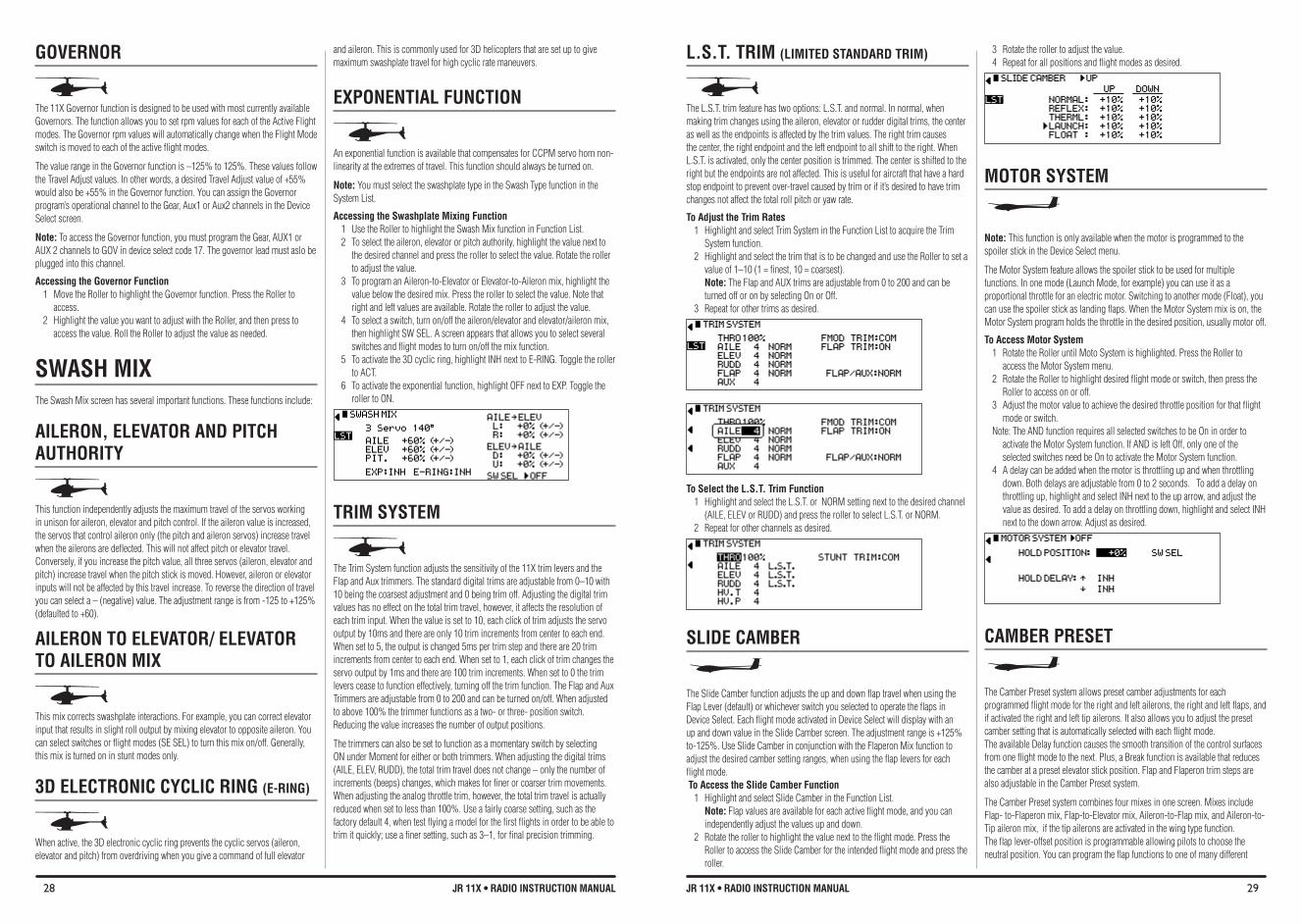
28 JR 11X • RADIO INSTRUCTION MANUAL 29JR 11X • RADIO INSTRUCTION MANUAL
GOvERNOR
The 11X Governor function is designed to be used with most currently available Governors. The function allows you to set rpm values for each of the Active Flight modes. The Governor rpm values will automatically change when the Flight Mode switch is moved to each of the active flight modes.
The value range in the Governor function is –125% to 125%. These values follow the Travel Adjust values. In other words, a desired Travel Adjust value of +55% would also be +55% in the Governor function. You can assign the Governor program’s operational channel to the Gear, Aux1 or Aux2 channels in the Device Select screen.
Note: To access the Governor function, you must program the Gear, AUX1 or AUX 2 channels to GOV in device select code 17. The governor lead must aslo be plugged into this channel.
Accessing the Governor function 1 Move the Roller to highlight the Governor function. Press the Roller to
access. 2 Highlight the value you want to adjust with the Roller, and then press to
access the value. Roll the Roller to adjust the value as needed.
SWASH MIX The Swash Mix screen has several important functions. These functions include:
AILERON, ELEvATOR AND PITCH AUTHORITY
This function independently adjusts the maximum travel of the servos working in unison for aileron, elevator and pitch control. If the aileron value is increased, the servos that control aileron only (the pitch and aileron servos) increase travel when the ailerons are deflected. This will not affect pitch or elevator travel. Conversely, if you increase the pitch value, all three servos (aileron, elevator and pitch) increase travel when the pitch stick is moved. However, aileron or elevator inputs will not be affected by this travel increase. To reverse the direction of travel you can select a – (negative) value. The adjustment range is from -125 to +125% (defaulted to +60).
AILERON TO ELEvATOR/ ELEvATOR TO AILERON MIX
This mix corrects swashplate interactions. For example, you can correct elevator input that results in slight roll output by mixing elevator to opposite aileron. You can select switches or flight modes (SE SEL) to turn this mix on/off. Generally, this mix is turned on in stunt modes only.
3D eLeCTRONIC CyCLIC RING (e-RING)
When active, the 3D electronic cyclic ring prevents the cyclic servos (aileron, elevator and pitch) from overdriving when you give a command of full elevator
and aileron. This is commonly used for 3D helicopters that are set up to give maximum swashplate travel for high cyclic rate maneuvers.
EXPONENTIAL fUNCTION
An exponential function is available that compensates for CCPM servo horn non-linearity at the extremes of travel. This function should always be turned on.
Note: You must select the swashplate type in the Swash Type function in the System List.
Accessing the Swashplate Mixing function 1 Use the Roller to highlight the Swash Mix function in Function List. 2 To select the aileron, elevator or pitch authority, highlight the value next to
the desired channel and press the roller to select the value. Rotate the roller to adjust the value.
3 To program an Aileron-to-Elevator or Elevator-to-Aileron mix, highlight the value below the desired mix. Press the roller to select the value. Note that right and left values are available. Rotate the roller to adjust the value.
4 To select a switch, turn on/off the aileron/elevator and elevator/aileron mix, then highlight SW SEL. A screen appears that allows you to select several switches and flight modes to turn on/off the mix function.
5 To activate the 3D cyclic ring, highlight INH next to E-RING. Toggle the roller to ACT.
6 To activate the exponential function, highlight OFF next to EXP. Toggle the roller to ON.
TRIM SYSTEM
The Trim System function adjusts the sensitivity of the 11X trim levers and the Flap and Aux trimmers. The standard digital trims are adjustable from 0–10 with 10 being the coarsest adjustment and 0 being trim off. Adjusting the digital trim values has no effect on the total trim travel, however, it affects the resolution of each trim input. When the value is set to 10, each click of trim adjusts the servo output by 10ms and there are only 10 trim increments from center to each end. When set to 5, the output is changed 5ms per trim step and there are 20 trim increments from center to each end. When set to 1, each click of trim changes the servo output by 1ms and there are 100 trim increments. When set to 0 the trim levers cease to function effectively, turning off the trim function. The Flap and Aux Trimmers are adjustable from 0 to 200 and can be turned on/off. When adjusted to above 100% the trimmer functions as a two- or three- position switch. Reducing the value increases the number of output positions.
The trimmers can also be set to function as a momentary switch by selecting ON under Moment for either or both trimmers. When adjusting the digital trims (AILE, ELEV, RUDD), the total trim travel does not change – only the number of increments (beeps) changes, which makes for finer or coarser trim movements. When adjusting the analog throttle trim, however, the total trim travel is actually reduced when set to less than 100%. Use a fairly coarse setting, such as the factory default 4, when test flying a model for the first flights in order to be able to trim it quickly; use a finer setting, such as 3–1, for final precision trimming.
L.S.T. TRIM (LIMITeD STANDARD TRIM)
The L.S.T. trim feature has two options: L.S.T. and normal. In normal, when making trim changes using the aileron, elevator or rudder digital trims, the center as well as the endpoints is affected by the trim values. The right trim causes the center, the right endpoint and the left endpoint to all shift to the right. When L.S.T. is activated, only the center position is trimmed. The center is shifted to the right but the endpoints are not affected. This is useful for aircraft that have a hard stop endpoint to prevent over-travel caused by trim or if it’s desired to have trim changes not affect the total roll pitch or yaw rate.
To Adjust the Trim Rates 1 Highlight and select Trim System in the Function List to acquire the Trim
System function. 2 Highlight and select the trim that is to be changed and use the Roller to set a
value of 1–10 (1 = finest, 10 = coarsest). Note: The Flap and AUX trims are adjustable from 0 to 200 and can be turned off or on by selecting On or Off.
3 Repeat for other trims as desired.
To Select the L.S.T. Trim function 1 Highlight and select the L.S.T. or NORM setting next to the desired channel
(AILE, ELEV or RUDD) and press the roller to select L.S.T. or NORM. 2 Repeat for other channels as desired.
SLIDE CAMbER
The Slide Camber function adjusts the up and down flap travel when using the Flap Lever (default) or whichever switch you selected to operate the flaps in Device Select. Each flight mode activated in Device Select will display with an up and down value in the Slide Camber screen. The adjustment range is +125% to-125%. Use Slide Camber in conjunction with the Flaperon Mix function to adjust the desired camber setting ranges, when using the flap levers for each flight mode. To Access the Slide Camber Function
1 Highlight and select Slide Camber in the Function List. Note: Flap values are available for each active flight mode, and you can independently adjust the values up and down.
2 Rotate the roller to highlight the value next to the flight mode. Press the Roller to access the Slide Camber for the intended flight mode and press the roller.
3 Rotate the roller to adjust the value. 4 Repeat for all positions and flight modes as desired.
MOTOR SYSTEM
Note: This function is only available when the motor is programmed to the spoiler stick in the Device Select menu.
The Motor System feature allows the spoiler stick to be used for multiple functions. In one mode (Launch Mode, for example) you can use it as a proportional throttle for an electric motor. Switching to another mode (Float), you can use the spoiler stick as landing flaps. When the Motor System mix is on, the Motor System program holds the throttle in the desired position, usually motor off.
To Access Motor System1 Rotate the Roller until Moto System is highlighted. Press the Roller to
access the Motor System menu. 2 Rotate the Roller to highlight desired flight mode or switch, then press the
Roller to access on or off. 3 Adjust the motor value to achieve the desired throttle position for that flight
mode or switch. Note: The AND function requires all selected switches to be On in order to
activate the Motor System function. If AND is left Off, only one of the selected switches need be On to activate the Motor System function.
4 A delay can be added when the motor is throttling up and when throttling down. Both delays are adjustable from 0 to 2 seconds. To add a delay on throttling up, highlight and select INH next to the up arrow, and adjust the value as desired. To add a delay on throttling down, highlight and select INH next to the down arrow. Adjust as desired.
CAMbER PRESET
The Camber Preset system allows preset camber adjustments for each programmed flight mode for the right and left ailerons, the right and left flaps, and if activated the right and left tip ailerons. It also allows you to adjust the preset camber setting that is automatically selected with each flight mode. The available Delay function causes the smooth transition of the control surfaces from one flight mode to the next. Plus, a Break function is available that reduces the camber at a preset elevator stick position. Flap and Flaperon trim steps are also adjustable in the Camber Preset system.
The Camber Preset system combines four mixes in one screen. Mixes include Flap- to-Flaperon mix, Flap-to-Elevator mix, Aileron-to-Flap mix, and Aileron-to-Tip aileron mix, if the tip ailerons are activated in the wing type function. The flap lever-offset position is programmable allowing pilots to choose the neutral position. You can program the flap functions to one of many different
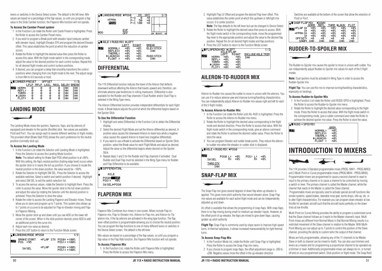
30 JR 11X • RADIO INSTRUCTION MANUAL 31JR 11X • RADIO INSTRUCTION MANUAL
levers or switches in the Device Select screen. The default is the left lever. Mix values are based on a percentage of the flap values, so until you program a flap value in the Slide Camber function, the Flaperon Mix function will not operate.
To Access the Camber Preset system 1 In the Function List rotate the Roller until Camb Preset is highlighted. Press
the Roller to access the Camber Preset menu. 2 If you wish to program a Break point with elevator input (reduces camber
with elevator input), highlight Elevator STK and program the desired Elevator offset. This value establishes the point at which the reduction of camber occurs.
3 Rotate the Roller to highlight the desired value then press the Roller to access this value. With the flight mode switch in the corresponding mode, adjust the value to the desired position for each control surface. Repeat this for all desired flight modes and control surface positions.
4 If desired, you can program a delay that smoothly transitions the control positions when changing from one flight mode to the next. The adjust range is from INH to 6.0 seconds or hold.
LANDING MODE
The Landing Mode mixes the spoilers, flaperons, flaps, and tip ailerons (if equipped) and elevator to the spoiler (throttle) stick. Two values are available, Pos0 and Pos1. You can assign each to several different switches or flight modes. The provided offset (Brake Start POS) allows the user’s preference for the neutral position (normally stick up).
To Access the Landing Mode1 In the Function List rotate the Selector until Landing Mode is highlighted.
Press the Selector to access the Landing Mode function. Note: The default setting for Brake Start POS offset position is at +95%. With this setting, the flap’s neutral position (trailing edge level) occurs when the spoiler stick is in nearly the full up position. If you choose to locate the neutral position in the down position, the value would be –100%.
2 Rotate the Selector to highlight SW SEL. Press the Selector to access the available switches. Select a switch and switch position if desired. Highlight and select SW SEL to exit the switch selection list.
3 To access the various values, rotate the Selector to highlight them. Press the roller to access the value. Move the spoiler stick to the full down position and adjust the value by rotating the Selector until the desired position is achieved. Press the Selector to store the value.
4 Rotate the roller to access the Landing Flaperon and Elevator mixes. These allow you to store and program up to 7 points. This system also allows up to 7 points on a curve to be adjusted for Flap-to-Elevator mixing and Flap-to-Flaperon Mixing.
5 Move the spoiler stick up and down until you see ADD on the lower left corner of the screen. When in the stick position desired, press ADD to add an additional point to the curve mix.
6 Adjust each mix value as desired.7 Press the LIST button to return to the Function Mode screen.
2 Highlight Flap LV Offset and program the desired Flap lever offset. This value establishes the center point at which the up/down or left/right mix occurs. 0 is center position. Note: The flap defaults to the left lever but can be changed in Device Select.
3 Rotate the Roller to highlight the desired value then press to access. With the flight mode switch in the corresponding mode, move the programmed flap lever to the appropriate position and adjust the value to the desired flap position. Repeat this for all desired flight modes and flap positions.
4 Press the LIST button to return to the Function Mode screen.
AILERON-TO-RUDDER MIX
Aileron-to-Rudder mix causes the rudder to move in unison with the ailerons. You can use it to reduce adverse yaw and improve turning/handling characteristics. You can independently adjust Aileron-to-Rudder mix values right and left for each of the 5 flight modes.
To Access Aileron-to-Rudder Mix 1 In the Function List rotate the Roller until AIL-RUD is highlighted. Press the
Roller to access the Aileron-to-Rudder mix menu.2 Rotate the Roller to highlight the desired value corresponding to the flight
mode and desired direction. Press the Roller to access that value. With the flight mode switch in the corresponding mode, give an aileron command and rotate the Roller to achieve the desired rudder value. Press the Roller to store the value.
3 You can program Elevator and rudder break points. They reduce the aileron-to-rudder mix when the elevator or rudder stick is displaced.
SNAP-fLAP MIX
The Snap-Flap mix gives several degrees of down flap when up elevator is applied. This gives more pitch authority than would elevator alone. Snap-Flap mix values are available for each active flight mode and can be independently adjusted up and down.
An offset is available that allows the programming of snap-flaps. With snap-flaps, there is no flap mixing during small-to-medium up-elevator inputs. However, at the offset point of up-elevator, the flaps are mixed to give down flaps, causing greater up-pitch authority
flight Tip: Snap-Flap is commonly used by slope racers to improve high-speed turns. In thermal sailplanes, it allows increased maneuverability for tight thermal turns.
To Access Snap-flap Mix 1 In the Function Mode list, rotate the Roller until Snap-Flap is highlighted.
Press the Roller to access the Snap-Flap mix menu. 2 If you choose to program snap-flaps, the offset adjustment range is -200 to
+200. Negative values move the offset in the up-elevator direction.
DIffERENTIAL
The 11X Differential function reduces the travel of the Aileron that deflects downward without affecting the Aileron that travels upward and, therefore, can eliminate adverse yaw tendencies in rolling maneuvers. Differential is also available for the Rudder and Flap channels if Dual Rudder and/or Dual Flap is selected in the Wing Type menu.
The Aileron Differential function provides independent differentials for each flight mode. A Break feature adjusts the point at which the differential begins based on the Spoiler Stick.
To Use the Differential function 1 Highlight and select Differential in the Function List to obtain the Differential
display. 2 Select the desired Flight Mode and set the Aileron differential as desired. A
positive value causes the downward Aileron to travel less while a negative value causes the upward Aileron to travel less (negative differential).
3 If you want to use a Break to activate the Differential based on Spoiler Stick position, select the Break value for each Flight Mode and adjust as desired. Adjust the value so the differential begins where desired on the Spoiler Stick.
4 Repeat steps 1 and 2 for the Rudder and Flap channels if activated. Dual Rudder and Dual Flap must be selected in the Wing Type menu for Rudder and Flap Differential to be available.
fLAPERON MIX
Flaperon Mix Combines four mixes in one screen. Mixes include Flap-to-Flaperon mix, Flap-to-Elevator mix, Aileron-to-Flap mix, and Aileron-to-Tip aileron mix, if the tip ailerons are activated in the wing type function. The flap lever-offset position is programmable allowing you to choose the neutral position. You can program the flap functions to one of many different levers or switches in the Device Select screen. The default is the left lever.
Mix values are based on a percentage of the flap values, so until you program a flap value in the Flap Rate function, the Flaperon Mix function will not operate.
To Access flaperon Mix1. In the Function List, rotate the Roller until Flaperon Mix is highlighted.
Press the Roller to access the Flaperon Mix menu.
Switches are available at the bottom of the screen that allow the selection of Pos0 or Pos1.
RUDDER-TO-SPOILER MIX
The Rudder-to-Spoiler mix causes the spoiler to move in unison with rudder. You can independently adjust Rudder-to-Spoiler mix values for each of the 5 flight modes.
Note: Dual spoilers must be activated in Wing Type in order to access the Rudder-Spoiler mix.
flight Tip: You can use this mix to improve turning/handling characteristics, especially on landings.
To Access Rudder-to-Spoiler Mix 1 In the Function List rotate the Roller until RUDD-SPOI is highlighted. Press
the Roller to access the Rudder-to-Spoiler mix menu.2 Rotate the Roller to highlight the desired value corresponding to the flight
mode. Press the Roller to access that value. With the flight mode switch in the corresponding mode, give a rudder command and rotate the Roller to achieve the desired spoiler mix value. Press the Roller to store the value.
INTRODUCTION TO MIXERS
The 11X provides 3 Standard programmable mixes (PROG. MIX1 - PROG.MIX3) and 3 Multi-Point or Curve programmable mixes (PROG.MIX4 - PROG.MIX6). Programmable mixers are programmed to cause a second channel to react to input to the primary channel or to cause a channel to be controlled by moving a switch or lever. The primary channel is called the Master channel, while the channel that reacts to the Master is called the Slave channel. Programmable mixes are typically used to activate special aircraft functions like smoke systems, speed brakes, steerable nose gear, bomb drops, idle-up, etc. or to alter flight characteristics. For example you can program down elevator at low throttle for aerobatic aircraft such that the aircraft tracks perfectly on the down lines at low throttle.
Multi-Point (or Curve) Mixing provides the ability to program a customized curve that the Slave channel follows as it reacts to the Master channel’s input. Multi Point mixes are different from Normal Mixes in that Normal Mixing results in a restricted movement of the Slave channel in relation to the Master. With Multi-Point Mixing you can adjust up to 7 points to control the position of the Slave channel, providing the ability to custom tailor the output of that channel.
Mixes are fully programmable, allowing any of the 11 channels to be Master, Slave or both (a channel can be mixed to itself). You can also use trimmers and levers as a master and for programming a proportional channel to be operated via a trimmer or lever. Additionally programmable mixes can always be on, or turned off and on via a programmed switch, Stick position or flight mode. The Snap Roll/
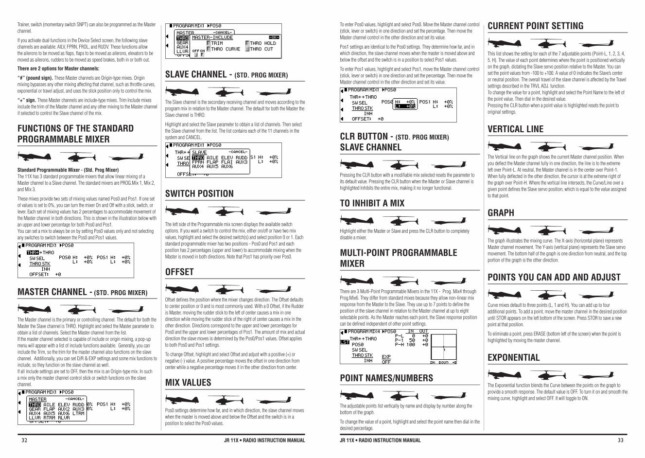
32 JR 11X • RADIO INSTRUCTION MANUAL 33JR 11X • RADIO INSTRUCTION MANUAL
Trainer, switch (momentary switch SNPT) can also be programmed as the Master channel.
If you activate dual functions in the Device Select screen, the following slave channels are available: AILV, FPRN, FROL, and RUDV. These functions allow the ailerons to be moved as flaps, flaps to be moved as ailerons, elevators to be moved as ailerons, rudders to be moved as speed brakes, both in or both out.
There are 2 options for Master channels:
“#” (pound sign). These Master channels are Origin-type mixes. Origin mixing bypasses any other mixing affecting that channel, such as throttle curves, exponential or travel adjust, and uses the stick position only to control the mix.
“+” sign. These Master channels are include-type mixes. Trim Include mixes include the trim of the Master channel and any other mixing to the Master channel if selected to control the Slave channel of the mix.
fUNCTIONS Of THE STANDARD PROGRAMMAbLE MIXER
Standard Programmable Mixer - (Std. Prog Mixer)The 11X has 3 standard programmable mixers that allow linear mixing of a Master channel to a Slave channel. The standard mixers are PROG.Mix 1, Mix 2, and Mix 3.
These mixes provide two sets of mixing values named Pos0 and Pos1. If one set of values is set to 0%, you can turn the mixer On and Off with a stick, switch, or lever. Each set of mixing values has 2 percentages to accommodate movement of the Master channel in both directions. This is shown in the illustration below with an upper and lower percentage for both Pos0 and Pos1. You can set a mix to always be on by setting Pos0 values only and not selecting any switches to switch between the Pos0 and Pos1 values.
MASTER CHANNEL - (STD. PROG MIXeR)
The Master channel is the primary or controlling channel. The default for both the Master the Slave channel is THRO. Highlight and select the Master parameter to obtain a list of channels. Select the Master channel from the list. If the master channel selected is capable of include or origin mixing, a pop-up menu will appear with a list of include functions available. Generally, you can include the Trim, so the trim for the master channel also functions on the slave channel. Additionally, you can set D/R & EXP settings and some mix functions to include, so they function on the slave channel as well. If all include settings are set to OFF, then the mix is an Origin-type mix. In such a mix only the master channel control stick or switch functions on the slave channel.
To enter Pos0 values, highlight and select Pos0. Move the Master channel control (stick, lever or switch) in one direction and set the percentage. Then move the Master channel control in the other direction and set its value.
Pos1 settings are identical to the Pos0 settings. They determine how far, and in which direction, the slave channel moves when the master is moved above and below the offset and the switch is in a position to select Pos1 values.
To enter Pos1 values, highlight and select Pos1, move the Master channel control (stick, lever or switch) in one direction and set the percentage. Then move the Master channel control in the other direction and set its value.
CLR bUTTON - (STD. PROG MIXeR) SLAvE CHANNEL
Pressing the CLR button with a modifiable mix selected resets the parameter to its default value. Pressing the CLR button when the Master or Slave channel is highlighted Inhibits the entire mix, making it no longer functional.
TO INHIbIT A MIX
Highlight either the Master or Slave and press the CLR button to completely disable a mixer.
MULTI-POINT PROGRAMMAbLE MIXER
There are 3 Multi-Point Programmable Mixers in the 11X - Prog. Mix4 through Prog.Mix6. They differ from standard mixes because they allow non-linear mix response from the Master to the Slave. They use up to 7 points to define the position of the slave channel in relation to the Master channel at up to eight selectable points. As the Master reaches each point, the Slave response position can be defined independent of other point settings.
POINT NAMES/NUMbERS
The adjustable points list vertically by name and display by number along the bottom of the graph.
To change the value of a point, highlight and select the point name then dial in the desired percentage.
SLAvE CHANNEL - (STD. PROG MIXeR)
The Slave channel is the secondary receiving channel and moves according to the program mix in relation to the Master channel. The default for both the Master the Slave channel is THRO.
Highlight and select the Slave parameter to obtain a list of channels. Then select the Slave channel from the list. The list contains each of the 11 channels in the system and CANCEL.
SWITCH POSITION
The left side of the Programmable mix screen displays the available switch options. If you want a switch to control the mix, either on/off or have two mix values, highlight and select the desired switch(s) and select position 0 or 1. Each standard programmable mixer has two positions - Pos0 and Pos1 and each position has 2 percentages (upper and lower) to accommodate mixing when the Master is moved in both directions. Note that Pos1 has priority over Pos0.
OffSET
Offset defines the position where the mixer changes direction. The Offset defaults to center position or 0 and is most commonly used. With a 0 Offset, if the Rudder is Master, moving the rudder stick to the left of center causes a mix in one direction while moving the rudder stick of the right of center causes a mix in the other direction. Directions correspond to the upper and lower percentages for Pos0 and the upper and lower percentages of Pos1. The amount of mix and actual direction the slave moves is determined by the Pos0/Pos1 values. Offset applies to both Pos0 and Pos1 settings.
To change Offset, highlight and select Offset and adjust with a positive (+) or negative (-) value. A positive percentage moves the offset in one direction from center while a negative percentage moves it in the other direction from center.
MIX vALUES
Pos0 settings determine how far, and in which direction, the slave channel moves when the master is moved above and below the Offset and the switch is in a position to select the Pos0 values.
CURRENT POINT SETTING
This list shows the setting for each of the 7 adjustable points (Point-L, 1, 2, 3, 4, 5, H). The value of each point determines where the point is positioned vertically on the graph, dictating the Slave servo position relative to the Master. You can set the point values from -100 to +100. A value of 0 indicates the Slave’s center or neutral position. The overall travel of the slave channel is affected by the Travel settings described in the TRVL ADJ. function. To change the value for a point, highlight and select the Point Name to the left of the point value. Then dial in the desired value. Pressing the CLR button when a point value is highlighted resets the point to original settings.
vERTICAL LINE
The Vertical line on the graph shows the current Master channel position. When you deflect the Master channel fully in one direction, the line is to the extreme left over Point-L. At neutral, the Master channel is in the center over Point-1. When fully deflected in the other direction, the cursor is at the extreme right of the graph over Point-H. Where the vertical line intersects, the Curve/Line over a given point defines the Slave servo position, which is equal to the value assigned to that point.
GRAPH
The graph illustrates the mixing curve. The X-axis (horizontal plane) represents Master channel movement. The Y-axis (vertical plane) represents the Slave servo movement. The bottom half of the graph is one direction from neutral, and the top portion of the graph is the other direction.
POINTS YOU CAN ADD AND ADJUST
Curve mixes default to three points (L, 1 and H). You can add up to four additional points. To add a point, move the master channel in the desired position until STOR appears on the left bottom of the screen. Press STOR to save a new point at that position.
To eliminate a point, press ERASE (bottom left of the screen) when the point is highlighted by moving the master channel.
EXPONENTIAL
The Exponential function blends the Curve between the points on the graph to provide a smooth response. The default value is OFF. To turn it on and smooth the mixing curve, highlight and select OFF. It will toggle to ON.
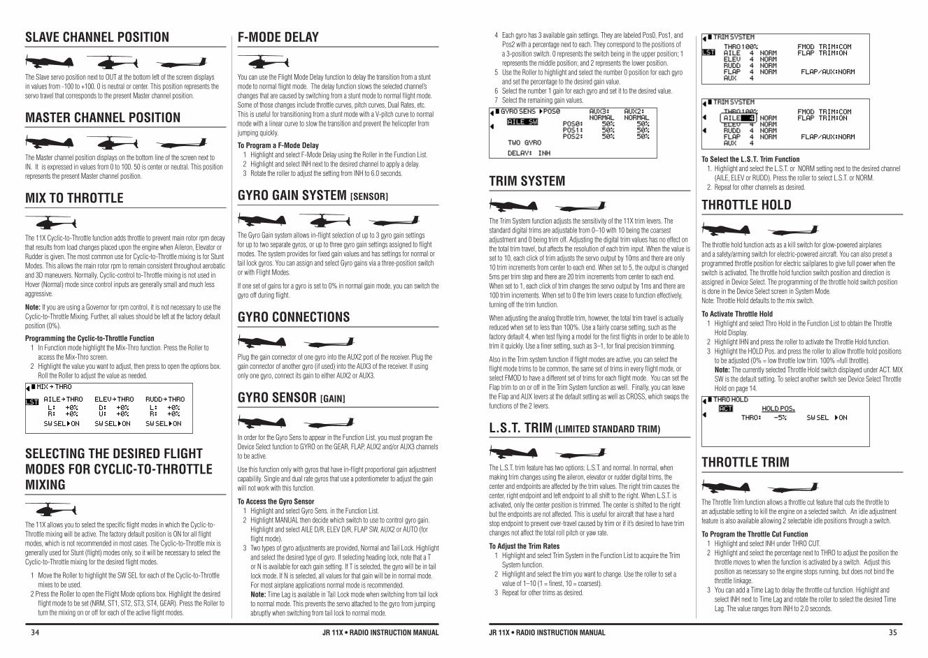
34 JR 11X • RADIO INSTRUCTION MANUAL 35JR 11X • RADIO INSTRUCTION MANUAL
SLAvE CHANNEL POSITION
The Slave servo position next to OUT at the bottom left of the screen displays in values from -100 to +100. 0 is neutral or center. This position represents the servo travel that corresponds to the present Master channel position.
MASTER CHANNEL POSITION
The Master channel position displays on the bottom line of the screen next to IN. It is expressed in values from 0 to 100. 50 is center or neutral. This position represents the present Master channel position.
MIX TO THROTTLE
The 11X Cyclic-to-Throttle function adds throttle to prevent main rotor rpm decay that results from load changes placed upon the engine when Aileron, Elevator or Rudder is given. The most common use for Cyclic-to-Throttle mixing is for Stunt Modes. This allows the main rotor rpm to remain consistent throughout aerobatic and 3D maneuvers. Normally, Cyclic-control to-Throttle mixing is not used in Hover (Normal) mode since control inputs are generally small and much less aggressive.
Note: If you are using a Governor for rpm control, it is not necessary to use the Cyclic-to-Throttle Mixing. Further, all values should be left at the factory default position (0%).
Programming the Cyclic-to-Throttle function 1 In Function mode highlight the Mix-Thro function. Press the Roller to
access the Mix-Thro screen. 2 Highlight the value you want to adjust, then press to open the options box.
Roll the Roller to adjust the value as needed.
SELECTING THE DESIRED fLIGHT MODES fOR CYCLIC-TO-THROTTLE MIXING
The 11X allows you to select the specific flight modes in which the Cyclic-to-Throttle mixing will be active. The factory default position is ON for all flight modes, which is not recommended in most cases. The Cyclic-to-Throttle mix is generally used for Stunt (flight) modes only, so it will be necessary to select the Cyclic-to-Throttle mixing for the desired flight modes.
1 Move the Roller to highlight the SW SEL for each of the Cyclic-to-Throttle mixes to be used.
2 Press the Roller to open the Flight Mode options box. Highlight the desired flight mode to be set (NRM, ST1, ST2, ST3, ST4, GEAR). Press the Roller to turn the mixing on or off for each of the active flight modes.
4 Each gyro has 3 available gain settings. They are labeled Pos0, Pos1, and Pos2 with a percentage next to each. They correspond to the positions of a 3-position switch. 0 represents the switch being in the upper position; 1 represents the middle position; and 2 represents the lower position.
5 Use the Roller to highlight and select the number 0 position for each gyro and set the percentage to the desired gain value.
6 Select the number 1 gain for each gyro and set it to the desired value. 7 Select the remaining gain values.
TRIM SYSTEM
The Trim System function adjusts the sensitivity of the 11X trim levers. The standard digital trims are adjustable from 0–10 with 10 being the coarsest adjustment and 0 being trim off. Adjusting the digital trim values has no effect on the total trim travel, but affects the resolution of each trim input. When the value is set to 10, each click of trim adjusts the servo output by 10ms and there are only 10 trim increments from center to each end. When set to 5, the output is changed 5ms per trim step and there are 20 trim increments from center to each end. When set to 1, each click of trim changes the servo output by 1ms and there are 100 trim increments. When set to 0 the trim levers cease to function effectively, turning off the trim function.
When adjusting the analog throttle trim, however, the total trim travel is actually reduced when set to less than 100%. Use a fairly coarse setting, such as the factory default 4, when test flying a model for the first flights in order to be able to trim it quickly. Use a finer setting, such as 3–1, for final precision trimming.
Also in the Trim system function if flight modes are active, you can select the flight mode trims to be common, the same set of trims in every flight mode, or select FMOD to have a different set of trims for each flight mode. You can set the Flap trim to on or off in the Trim System function as well. Finally, you can leave the Flap and AUX levers at the default setting as well as CROSS, which swaps the functions of the 2 levers.
L.S.T. TRIM (LIMITeD STANDARD TRIM)
The L.S.T. trim feature has two options: L.S.T. and normal. In normal, when making trim changes using the aileron, elevator or rudder digital trims, the center and endpoints are affected by the trim values. The right trim causes the center, right endpoint and left endpoint to all shift to the right. When L.S.T. is activated, only the center position is trimmed. The center is shifted to the right but the endpoints are not affected. This is useful for aircraft that have a hard stop endpoint to prevent over-travel caused by trim or if it’s desired to have trim changes not affect the total roll pitch or yaw rate.
To Adjust the Trim Rates 1 Highlight and select Trim System in the Function List to acquire the Trim
System function. 2 Highlight and select the trim you want to change. Use the roller to set a
value of 1–10 (1 = finest, 10 = coarsest). 3 Repeat for other trims as desired.
f-MODE DELAY
You can use the Flight Mode Delay function to delay the transition from a stunt mode to normal flight mode. The delay function slows the selected channel’s changes that are caused by switching from a stunt mode to normal flight mode. Some of those changes include throttle curves, pitch curves, Dual Rates, etc. This is useful for transitioning from a stunt mode with a V-pitch curve to normal mode with a linear curve to slow the transition and prevent the helicopter from jumping quickly.
To Program a f-Mode Delay1 Highlight and select F-Mode Delay using the Roller in the Function List.2 Highlight and select INH next to the desired channel to apply a delay.3 Rotate the roller to adjust the setting from INH to 6.0 seconds.
GYRO GAIN SYSTEM [SeNSOR]
The Gyro Gain system allows in-flight selection of up to 3 gyro gain settings for up to two separate gyros, or up to three gyro gain settings assigned to flight modes. The system provides for fixed gain values and has settings for normal or tail lock gyros. You can assign and select Gyro gains via a three-position switch or with Flight Modes.
If one set of gains for a gyro is set to 0% in normal gain mode, you can switch the gyro off during flight.
GYRO CONNECTIONS
Plug the gain connector of one gyro into the AUX2 port of the receiver. Plug the gain connector of another gyro (if used) into the AUX3 of the receiver. If using only one gyro, connect its gain to either AUX2 or AUX3.
GYRO SENSOR [GAIN]
In order for the Gyro Sens to appear in the Function List, you must program the Device Select function to GYRO on the GEAR, FLAP, AUX2 and/or AUX3 channels to be active.
Use this function only with gyros that have in-flight proportional gain adjustment capability. Single and dual rate gyros that use a potentiometer to adjust the gain will not work with this function.
To Access the Gyro Sensor 1 Highlight and select Gyro Sens. in the Function List. 2 Highlight MANUAL then decide which switch to use to control gyro gain.
Highlight and select AILE D/R, ELEV D/R, FLAP SW, AUX2 or AUTO (for flight mode).
3 Two types of gyro adjustments are provided, Normal and Tail Lock. Highlight and select the desired type of gyro. If selecting heading lock, note that a T or N is available for each gain setting. If T is selected, the gyro will be in tail lock mode. If N is selected, all values for that gain will be in normal mode. For most airplane applications normal mode is recommended. Note: Time Lag is available in Tail Lock mode when switching from tail lock to normal mode. This prevents the servo attached to the gyro from jumping abruptly when switching from tail lock to normal mode.
To Select the L.S.T. Trim function 1. Highlight and select the L.S.T. or NORM setting next to the desired channel
(AILE, ELEV or RUDD). Press the roller to select L.S.T. or NORM. 2. Repeat for other channels as desired.
THROTTLE HOLD
The throttle hold function acts as a kill switch for glow-powered airplanes and a safety/arming switch for electric-powered aircraft. You can also preset a programmed throttle position for electric sailplanes to give full power when the switch is activated. The throttle hold function switch position and direction is assigned in Device Select. The programming of the throttle hold switch position is done in the Device Select screen in System Mode.Note: Throttle Hold defaults to the mix switch.
To Activate Throttle Hold 1 Highlight and select Thro Hold in the Function List to obtain the Throttle
Hold Display. 2 Highlight IHN and press the roller to activate the Throttle Hold function. 3 Highlight the HOLD Pos. and press the roller to allow throttle hold positions
to be adjusted (0% = low throttle low trim. 100% =full throttle). Note: The currently selected Throttle Hold switch displayed under ACT. MIX SW is the default setting. To select another switch see Device Select Throttle Hold on page 14.
THROTTLE TRIM
The Throttle Trim function allows a throttle cut feature that cuts the throttle to an adjustable setting to kill the engine on a selected switch. An idle adjustment feature is also available allowing 2 selectable idle positions through a switch.
To Program the Throttle Cut function1 Highlight and select INH under THRO CUT.2 Highlight and select the percentage next to THRO to adjust the position the
throttle moves to when the function is activated by a switch. Adjust this position as necessary so the engine stops running, but does not bind the throttle linkage.
3 You can add a Time Lag to delay the throttle cut function. Highlight and select INH next to Time Lag and rotate the roller to select the desired Time Lag. The value ranges from INH to 2.0 seconds.
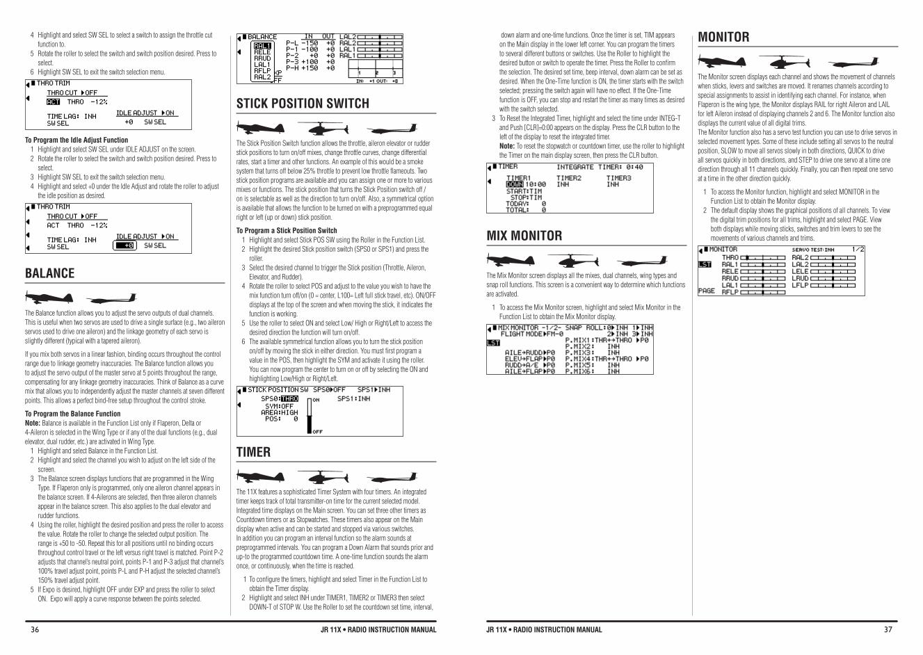
36 JR 11X • RADIO INSTRUCTION MANUAL 37JR 11X • RADIO INSTRUCTION MANUAL
4 Highlight and select SW SEL to select a switch to assign the throttle cut function to.
5 Rotate the roller to select the switch and switch position desired. Press to select.
6 Highlight SW SEL to exit the switch selection menu.
To Program the Idle Adjust function1 Highlight and select SW SEL under IDLE ADJUST on the screen.2 Rotate the roller to select the switch and switch position desired. Press to
select.3 Highlight SW SEL to exit the switch selection menu.4 Highlight and select +0 under the Idle Adjust and rotate the roller to adjust
the idle position as desired.
bALANCE
The Balance function allows you to adjust the servo outputs of dual channels. This is useful when two servos are used to drive a single surface (e.g., two aileron servos used to drive one aileron) and the linkage geometry of each servo is slightly different (typical with a tapered aileron).
If you mix both servos in a linear fashion, binding occurs throughout the control range due to linkage geometry inaccuracies. The Balance function allows you to adjust the servo output of the master servo at 5 points throughout the range, compensating for any linkage geometry inaccuracies. Think of Balance as a curve mix that allows you to independently adjust the master channels at seven different points. This allows a perfect bind-free setup throughout the control stroke.
To Program the balance function Note: Balance is available in the Function List only if Flaperon, Delta or 4-Aileron is selected in the Wing Type or if any of the dual functions (e.g., dual elevator, dual rudder, etc.) are activated in Wing Type.
1 Highlight and select Balance in the Function List.2 Highlight and select the channel you wish to adjust on the left side of the
screen. 3 The Balance screen displays functions that are programmed in the Wing
Type. If Flaperon only is programmed, only one aileron channel appears in the balance screen. If 4-Ailerons are selected, then three aileron channels appear in the balance screen. This also applies to the dual elevator and rudder functions.
4 Using the roller, highlight the desired position and press the roller to access the value. Rotate the roller to change the selected output position. The range is +50 to -50. Repeat this for all positions until no binding occurs throughout control travel or the left versus right travel is matched. Point P-2 adjusts that channel’s neutral point, points P-1 and P-3 adjust that channel’s 100% travel adjust point, points P-L and P-H adjust the selected channel’s 150% travel adjust point.
5 If Expo is desired, highlight OFF under EXP and press the roller to select ON. Expo will apply a curve response between the points selected.
down alarm and one-time functions. Once the timer is set, TIM appears on the Main display in the lower left corner. You can program the timers to several different buttons or switches. Use the Roller to highlight the desired button or switch to operate the timer. Press the Roller to confirm the selection. The desired set time, beep interval, down alarm can be set as desired. When the One-Time function is ON, the timer starts with the switch selected; pressing the switch again will have no effect. If the One-Time function is OFF, you can stop and restart the timer as many times as desired with the switch selected.
3 To Reset the Integrated Timer, highlight and select the time under INTEG-T and Push [CLR]=0:00 appears on the display. Press the CLR button to the left of the display to reset the integrated timer. Note: To reset the stopwatch or countdown timer, use the roller to highlight the Timer on the main display screen, then press the CLR button.
MIX MONITOR
The Mix Monitor screen displays all the mixes, dual channels, wing types and snap roll functions. This screen is a convenient way to determine which functions are activated.
1 To access the Mix Monitor screen, highlight and select Mix Monitor in the Function List to obtain the Mix Monitor display.
STICK POSITION SWITCH
The Stick Position Switch function allows the throttle, aileron elevator or rudder stick positions to turn on/off mixes, change throttle curves, change differential rates, start a timer and other functions. An example of this would be a smoke system that turns off below 25% throttle to prevent low throttle flameouts. Two stick position programs are available and you can assign one or more to various mixes or functions. The stick position that turns the Stick Position switch off /on is selectable as well as the direction to turn on/off. Also, a symmetrical option is available that allows the function to be turned on with a preprogrammed equal right or left (up or down) stick position.
To Program a Stick Position Switch 1 Highlight and select Stick POS SW using the Roller in the Function List. 2 Highlight the desired Stick position switch (SPS0 or SPS1) and press the
roller. 3 Select the desired channel to trigger the Stick position (Throttle, Aileron,
Elevator, and Rudder). 4 Rotate the roller to select POS and adjust to the value you wish to have the
mix function turn off/on (0 = center, L100= Left full stick travel, etc). ON/OFF displays at the top of the screen and when moving the stick, it indicates the function is working.
5 Use the roller to select ON and select Low/ High or Right/Left to access the desired direction the function will turn on/off.
6 The available symmetrical function allows you to turn the stick position on/off by moving the stick in either direction. You must first program a value in the POS, then highlight the SYM and activate it using the roller. You can now program the center to turn on or off by selecting the ON and highlighting Low/High or Right/Left.
TIMER
The 11X features a sophisticated Timer System with four timers. An integrated timer keeps track of total transmitter-on time for the current selected model. Integrated time displays on the Main screen. You can set three other timers as Countdown timers or as Stopwatches. These timers also appear on the Main display when active and can be started and stopped via various switches. In addition you can program an interval function so the alarm sounds at preprogrammed intervals. You can program a Down Alarm that sounds prior and up-to the programmed countdown time. A one-time function sounds the alarm once, or continuously, when the time is reached.
1 To configure the timers, highlight and select Timer in the Function List to obtain the Timer display.
2 Highlight and select INH under TIMER1, TIMER2 or TIMER3 then select DOWN-T of STOP W. Use the Roller to set the countdown set time, interval,
MONITOR
The Monitor screen displays each channel and shows the movement of channels when sticks, levers and switches are moved. It renames channels according to special assignments to assist in identifying each channel. For instance, when Flaperon is the wing type, the Monitor displays RAIL for right Aileron and LAIL for left Aileron instead of displaying channels 2 and 6. The Monitor function also displays the current value of all digital trims.The Monitor function also has a servo test function you can use to drive servos in selected movement types. Some of these include setting all servos to the neutral position, SLOW to move all servos slowly in both directions, QUICK to drive all servos quickly in both directions, and STEP to drive one servo at a time one direction through all 11 channels quickly. Finally, you can then repeat one servo at a time in the other direction quickly.
1 To access the Monitor function, highlight and select MONITOR in the Function List to obtain the Monitor display.
2 The default display shows the graphical positions of all channels. To view the digital trim positions for all trims, highlight and select PAGE. View both displays while moving sticks, switches and trim levers to see the movements of various channels and trims.
38 JR 11X • RADIO INSTRUCTION MANUAL 39JR 11X • RADIO INSTRUCTION MANUAL
Your DSM2 equipped 2.4GHz system is intuitive to operate, functioning nearly identically to FM systems. Following are a few common questions from customers:
Q: After I’ve bound the receiver to my transmitter, which do I turn on first when I want to fly?
A: Either one. Every DSM 2.4GHz transmitter has a GUID (Globally Unique Identifier) code imbedded in its signal. When you bind a DSM receiver to your transmitter, this GUID code is stored in the receiver. If you turn the receiver on before the transmitter, you don’t have to worry about it responding to another transmitter. The receiver will inhibit throttle output and drive all controls to preset positions while it waits for a signal from the transmitter with the same GUID code it has stored. If a DSM transmitter is turned on first you can expect it to connect within 6 seconds of powering on the receiver.
Q: Sometimes the system takes longer to connect or doesn’t connect at all. Why?
A: In order for a DSM system to connect, the receiver must receive a large number of uninterrupted signal packets from the transmitter. This process takes just a few seconds, but if the transmitter is too close to the receiver (within 4 feet) or near metal objects it may detect its own reflected 2.4GHz energy as “noise”. This can delay or prevent connection. If this happens make sure you are a sufficient distance from metal objects and the receiver itself before you power up and try again.
Q: Is it true that DSM systems are less tolerant of low voltage?A: All DSM receivers require at least 3.5V to operate normally. Most servos
cease to operate below 3.8V. Using multiple high-voltage servos, however, with an inadequate power supply can allow voltage to momentarily drop below 3.5V. This will cause the receiver to “brown out” and reconnect. All recently manufactured JR and Spektrum DSM receivers feature QuickConnect technology that will reconnect the system within a quarter of a second should a brownout occur. In addition, the receiver’s LED will flash, indicating a brownout has occurred. If after landing you notice your DSM receiver’s LED is flashing, make sure you have adequate power before you fly again.
Q: Sometimes when I power on my DSM system I notice the receiver won’t connect and it needs to be rebound to the transmitter. Can this happen in flight?
A: No. A DSM receiver cannot be unbound from its transmitter without specific action by the user. You can accidentally unbind a receiver by inadvertently pressing the bind button on your transmitter when you turn it on. This causes the transmitter to go into bind mode. If this happens and the transmitter doesn’t detect a binding signal from the receiver it can cause the receiver to be unbound. Some transmitter stands can cause the bind button to be depressed during power up, but these instances are extremely rare. If your system fails to connect, chances are much greater that it’s the result of one of the following conditions and not because the receiver is unbound. 1. You’ve selected the wrong model memory. 2. The transmitter is too close to conductive material to connect (see FAQ #2).
Q: How important is it that I test my system using a Spektrum flight Log?
A: All 2.4GHz signals, not just DSM, are affected by proximity to conductive materials such as carbon fiber or metal. Few RTF and ARF sport airplanes or helicopters use enough of these kinds of materials for it to be an issue. If, however, you’re flying a sophisticated model that uses a lot of conductive materials in its construction, a Flight Log can be helpful. The information it collects when you fly will help you determine the optimum location for your receiver(s) so you can minimize the effects of these materials on your signal performance. For more details on the Flight Log and how it works, visit SpektrumRC.com.
GENERAL INfORMATION
Servo Precautions•Donotlubricateservogearsormotors.•Donotoverloadretractservosduringretractedorextendedconditions.Make
sure they are able to travel their full deflection. Overloading or stalling a servo can cause excessive current drain.
•Makesureallservosmovefreelythroughtheirrotationsandnolinkageshang up or bind. A binding control linkage can cause a servo to draw excessive current. A stalled servo can drain a battery pack in a matter of minutes.
•Correctanycontrolsurface“buzz”or“flutter”assoonasitisnoticedinflight, as this condition can destroy the feedback potentiometer in the servo. It may be extremely dangerous to ignore such “buzz” or “flutter.”
•Usethesuppliedrubbergrommetsandbrassservoeyeletswhenmountingyour servos. Do not over-tighten the servo mounting screws, as this negates the dampening effect of the rubber grommets.
•Ensuretheservohornissecurelyfastenedtotheservo.Useonlytheservoarm screws provided; the size is different from other manufacturers.
•Discontinuetouseservoarmswhentheybecome“yellowed”ordiscolored.Such servo arms may be brittle and can snap at any time, possibly causing the aircraft to crash.
•Checkallrelatedmountingscrewsandlinkagesfrequently.Aircraftoftenvibrate, causing linkages and screws to loosen.
General NotesRadio controlled models are a great source of pleasure. Unfortunately, they can also pose a potential hazard if not operated and maintained properly.
It is imperative to install your radio control system correctly. Additionally, your level of piloting competency must be high enough to ensure that you are able to control your aircraft under all conditions. If you are a newcomer to radio controlled flying, please seek help from an experienced pilot or your local hobby store.
Safety, Precautions, and WarningsAs the user of this product, you are solely responsible for operating it in a manner that does not endanger yourself and others or result in damage to the product or the property of others. Carefully follow the directions and warnings for this and any optional support equipment (chargers, rechargeable battery packs, etc.) that you use. This model is controlled by a radio signal that is subject to interference from many sources outside your control. This interference can cause momentary loss of control so it is necessary to always keep a safe distance in all directions around your model, as this margin will help to avoid collisions or injury.
• Alwaysoperateyourmodelinanopenareaawayfromcars,traffic,orpeople.
• Avoidoperatingyourmodelinthestreetwhereinjuryordamagecanoccur.• Neveroperatethemodeloutintothestreetorpopulatedareasforany
reason.• Neveroperateyourmodelwithlowtransmitterbatteries.• Carefullyfollowthedirectionsandwarningsforthisandanyoptional
support equipment (chargers, rechargeable battery packs, etc.) that you use.• Keepallchemicals,smallpartsandanythingelectricaloutofthereachof
children.• Moisturecausesdamagetoelectronics.Avoidwaterexposuretoall
equipment not specifically designed and protected for this purpose.
Safety Do’s and Don’ts for Pilots•Ensurethatyourbatterieshavebeenproperlychargedpriortoyourinitial
flight.•Keeptrackofthetimethesystemisturnedonsoyouwillknowhowlong
you can safely operate your system.
•Performagroundrangecheckpriortotheinitialflightoftheday.Seethe“Daily Flight Checks Section” for information.
•Checkallcontrolsurfacespriortoeachtakeoff.•Donotflyyourmodelnearspectators,parkingareasoranyotherareathat
could result in injury to people or damage of property.•Donotflyduringadverseweatherconditions.Poorvisibilitycancause
disorientation and loss of control of your aircraft. Strong winds can cause similar problems.
•Donotpointthetransmitterantennadirectlytowardthemodel.Theradiationpattern from the tip of the antenna is inherently low.
•Donottakechances.Ifatanytimeduringflightyouobserveanyerraticorabnormal operation, land immediately and do not resume flight until the cause of the problem has been ascertained and corrected. Safety can never be taken lightly.
Federal Aviation Administration
PurposeThis advisory outlines safety standards for operations of model aircraft. We encourage voluntary compliance with these standards.
BackgroundAttention has been drawn to the increase in model aircraft operation. There is a need for added caution when operating free flight and radio controlled craft in order to avoid creating a noise nuisance or a potential hazard to full-scale aircraft and persons and/or property on the surface.
Operating StandardsModelers generally are concerned with safety and exercise good judgment when flying model aircraft. However, in the interest of safer skies, we encourage operators of radio controlled and free flight models to comply with the following standards:
FReQUeNTLy ASkeD QUeSTIONS ON SPEKTRUM 2.4GHz
40 JR 11X • RADIO INSTRUCTION MANUAL 41JR 11X • RADIO INSTRUCTION MANUAL
a. Exercise vigilance in locating full-scale aircraft (get help if possible) so as not to create a collision hazard.
b. Select an operating site at sufficient distance from populated areas so you do not create a noise problem or a potential hazard.
c. Do not fly higher than 400 feet above the surface.d. Always operate more than three miles from the boundary of an airport unless
you are given permission to be closer by the appropriate air traffic control facility in the case of an airport for which a control zone has been designated or by the airport manager in the case of other airports.
e. Do not hesitate to ask for assistance in complying with these guidelines at the airport traffic control tower or air route traffic control center nearest the site of your proposed operation.
Information Provided ByDirector, Air Traffic Service Federal Aviation Administration, Washington, D.C.
Daily Flight Checks1. Check the battery voltage on both the transmitter and the receiver battery
packs. Do not fly below 4.3V on the transmitter or below 9V on the receiver. To do so can crash your aircraft.
Note: When you check these batteries, ensure that you have the polarities correct on your expanded scale voltmeter.
2. Check all hardware (linkages, screws, nuts, and bolts) prior to each day’s flight. Be sure that binding does not occur and that all parts are properly secured.
3. Ensure that all surfaces are moving in the proper manner.4. Perform a ground range check before each day’s flying session.5. Prior to starting your aircraft, turn off your transmitter, then turn it back
on. Do this each time you start your aircraft. If any critical switches are on without your knowledge, the transmitter alarm will warn you at this time.
6. Check that all trim levers are in the proper location.7. All servo pigtails and switch harness plugs should be secured in the
receiver. Make sure that the switch harness moves freely in both directions.
WARRANTY AND REPAIR POLICY
WARRANTY PERIOD
Exclusive Warranty- Horizon Hobby, Inc., (Horizon) warranties that the Products purchased (the “Product”) will be free from defects in materials and workmanship for a period of 3 (three) years from the date of purchase by the Purchaser.
3 yeAR LIMITeD WARRANTy
Horizon reserves the right to change or modify this warranty without notice and disclaims all other warranties, express or implied.
(a) This warranty is limited to the original Purchaser (“Purchaser”) and is not transferable. REPAIR OR REPLACEMENT AS PROVIDED UNDER THIS WARRANTY IS THE EXCLUSIVE REMEDY OF THE PURCHASER.
WARRANTY SERvICESQUeSTIONS, ASSISTANCe, AND RePAIRS
Your local hobby store and/or place of purchase cannot provide warranty support or repair. Once assembly, setup or use of the Product has been started, you must contact Horizon directly. This will enable Horizon to better answer your questions and service you in the event that you may need any assistance. For questions or assistance, please direct your email to [email protected], or call 877.504.0233 toll free to speak to a Product Support representative. You may also find information on our website at www.horizonhobby.com.
INSPECTION OR REPAIRS
If this Product needs to be inspected or repaired, please use the Horizon Online Repair Request submission process found on our website or call Horizon to obtain a Return Merchandise Authorization (RMA) number. Pack the Product securely using a shipping carton. Please note that original boxes may be included, but are not designed to withstand the rigors of shipping without additional protection. Ship via a carrier that provides tracking and insurance for lost or damaged parcels, as Horizon is not responsible for merchandise until it arrives and is accepted at our facility. An Online Repair Request is available at www.horizonhobby.com http://www.horizonhobby.com under the Repairs tab. If you do not have internet access, please contact Horizon Product Support to obtain a RMA number along with instructions for submitting your product for repair. You will be asked to provide your complete name, street address, email address and phone number where you can be reached during business days, your RMA number, a list of the included items, and a brief summary of the problem upon submission. Your original sales receipt must also be included for warranty consideration. Be sure your name, address, and RMA number are clearly written on the outside of the shipping carton.
WARRANTY INSPECTION AND REPAIRS
To receive warranty service, you must include your original sales receipt verifying the proof-of-purchase date. Provided warranty conditions have been met, your Product will be repaired or replaced free of charge. Repair or replacement decisions are at the sole discretion of Horizon Hobby.
Notice: Do not ship batteries to Horizon Hobby. If you have any issue with a battery, please contact the appropriate Horizon Product Support office.
This warranty covers only those Products purchased from an authorized Horizon dealer. Third party transactions are not covered by this warranty. Proof of purchase is required for warranty claims.
(b) Limitations- HORIZON MAKES NO WARRANTY OR REPRESENTATION, EXPRESS OR IMPLIED, ABOUT NON-INFRINGEMENT, MERCHANTABILITY OR FITNESS FOR A PARTICULAR PURPOSE OF THE PRODUCT. THE PURCHASER ACKNOWLEDGES THAT THEY ALONE HAVE DETERMINED THAT THE PRODUCT WILL SUITABLY MEET THE REQUIREMENTS OF THE PURCHASER’S INTENDED USE.
(c) Purchaser Remedy- Horizon’s sole obligation hereunder shall be that Horizon will, at its option, (i) repair or (ii) replace, any Product determined by Horizon to be defective. In the event of a defect, these are the Purchaser’s exclusive remedies. Horizon reserves the right to inspect any and all equipment involved in a warranty claim. Repair or replacement decisions are at the sole discretion of Horizon. This warranty does not cover cosmetic damage or damage due to acts of God, accident, misuse, abuse, negligence, commercial use, or modification of or to any part of the Product. This warranty does not cover damage due to improper installation, operation, maintenance, or attempted repair by anyone other than Horizon. Return of any goods by Purchaser must be approved in writing by Horizon before shipment.
DAMAGE LIMITS
HORIZON SHALL NOT BE LIABLE FOR SPECIAL, INDIRECT OR CONSEQUENTIAL DAMAGES, LOSS OF PROFITS OR PRODUCTION OR COMMERCIAL LOSS IN ANY WAY CONNECTED WITH THE PRODUCT, WHETHER SUCH CLAIM IS BASED IN CONTRACT, WARRANTY, NEGLIGENCE, OR STRICT LIABILITY. Further, in no event shall the liability of Horizon exceed the individual price of the Product on which liability is asserted. As Horizon has no control over use, setup, final assembly, modification or misuse, no liability shall be assumed nor accepted for any resulting damage or injury. By the act of use, setup or assembly, the user accepts all resulting liability.
If you as the Purchaser or user are not prepared to accept the liability associated with the use of this Product, you are advised to return this Product immediately in new and unused condition to the place of purchase.
Law: These Terms are governed by Illinois law (without regard to conflict of law principals).
NON-WARRANTY REPAIRS
Should your repair not be covered by warranty the repair will be completed and payment will be required without notification or estimate of the expense unless the expense exceeds 50% of the retail purchase cost. By submitting the item for repair you are agreeing to payment of the repair without notification. Repair estimates are available upon request. You must include this request with your repair. Non-warranty repair estimates will be billed a minimum of ½ hour of labor. In addition you will be billed for return freight. Please advise us of your preferred method of payment. Horizon accepts money orders and cashiers checks, as well as Visa, MasterCard, American Express, and Discover cards. By submitting any item to Horizon for inspection or repair, you are agreeing to Horizon’s Terms and Conditions found on our website under the Repairs tab. Please note: non-warranty repair is only available on electronics and model engines.
Notice: Electronics and engines requiring inspection or repair should be shipped to the following address:
Horizon Service Center 4105 Fieldstone Road Champaign, Illinois 61822, USA
All other Products requiring warranty inspection or repair should be shipped to the following address:
Horizon Product Support 4105 Fieldstone Road Champaign, Illinois 61822, USA
Please call 877-504-0233 with any questions or concerns regarding this product or warranty.
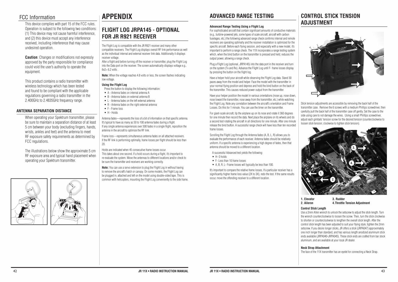
42 JR 11X • RADIO INSTRUCTION MANUAL 43JR 11X • RADIO INSTRUCTION MANUAL
FCC InformationThis device complies with part 15 of the FCC rules. Operation is subject to the following two conditions: (1) This device may not cause harmful interference, and (2) this device must accept any interference received, including interference that may cause undesired operation.
Caution: Changes or modifications not expressly approved by the party responsible for compliance could void the user’s authority to operate the equipment.
This product contains a radio transmitter with wireless technology which has been tested and found to be compliant with the applicable regulations governing a radio transmitter in the 2.400GHz to 2.4835GHz frequency range.
ANTENNA SEPARATION DISTANCE
When operating your Spektrum transmitter, please be sure to maintain a separation distance of at least 5 cm between your body (excluding fingers, hands, wrists, ankles and feet) and the antenna to meet RF exposure safety requirements as determined by FCC regulations.
The illustrations below show the approximate 5 cm RF exposure area and typical hand placement when operating your Spektrum transmitter.
APPENDIX
FLIGHT LOG JRPA145 - OPTIONAL FOR JR R921 ReCeIVeR The Flight Log is compatible with the JR R921 receiver and many other compatible receivers. The Flight Log displays overall RF link performance as well as the individual internal and external receiver link data. Additionally it displays receiver voltage. After a flight and before turning off the receiver or transmitter, plug the Flight Log into the Data port on the receiver. The screen automatically displays voltage e.g., 6v2= 6.2 volts .
Note: When the voltage reaches 4.8 volts or less, the screen flashes indicating low voltage.
Using the flight Log Press the button to display the following information: • A-AntennafadesoninternalantennaA• B-AntennafadesonexternalantennaB• L-Antennafadesontheleftexternalantenna• R-Antennafadesontherightexternalantenna• F-Frameloss• H-Holds
Antennafades—representsthelossofabitofinformationonthatspecificantenna.It’s typical to have as many as 50 to 100 antenna fades during a flight. If any single antenna experiences over 500 fades in a single flight, reposition the antenna in the aircraft to optimize the RF link.
Frameloss—representssimultaneousantennafadesonallattachedreceivers.If the RF link is performing optimally, frame losses per flight should be less than 20.
Holds are indicated when 45 consecutive frame losses occur. This takes about one second. If a hold occurs during a flight, it’s important to re-evaluate the system. Move the antennas to different locations and/or check to be sure the transmitter and receivers are working correctly.
Note: You can use a servo extension to plug the Flight Log in without having to remove the aircraft’s hatch or canopy. On some models, the Flight Log can be plugged in, attached and left on the model using double-sided tape. This is common with helicopters, mounting the Flight Log conveniently to the side frame.
ADvANCED RANGE TESTING
Advanced Range Testing Using a flight Log For sophisticated aircraft that contain significant amounts of conductive materials (e.g., turbine-powered jets, some types of scale aircraft, aircraft with carbon fuselages, etc.) the following advanced range check confirms internal and remote receivers are operating optimally and the receiver installation is optimized for the specific aircraft. Before each flying session, and especially with a new model, it’s important to perform a range check. The 11X incorporates a range testing system which, when the bind button on the transmitter is pressed and held, reduces the output power, allowing a range check.
Plug a Flight Log (optional, JRPA145) into the data port in the receiver and turn on the system (Tx and Rx). Advance the Flight Log until F- frame losses display by pressing the button on the flight log.
Have a helper hold your aircraft while observing the Flight Log data. Stand 30 paces away from the model and helper. Face the model with the transmitter in your normal flying position and depress and hold the bind button on the back of the transmitter. This causes reduced power output from the transmitter.
Have your helper position the model in various orientations (nose up, nose down, nose toward the transmitter, nose away from the transmitter, etc.) while watching the Flight Log. Note any correlation between the aircraft’s orientation and Frame Losses. Do this for 1 minute. You can use the timer on the transmitter.
For giant-scale aircraft, tip the airplane up on its nose and rotate it 360 degrees for one minute then record the data. Next place the airplane on its wheels and do a second test rotating the aircraft in all directions for one minute. After one minute release the bind button. A successful range check will have less than ten recorded frame losses.
Scrolling the Flight Log through the Antenna fades (A, B, L, R) allows you to evaluate the performance of each receiver. Antenna fades should be relatively uniform. If a specific antenna is experiencing a high degree of fades, then that antenna should be moved to a different location.
A successful Advanced test yields the following: • H-0holds• F-Lessthan10framelosses• A,B,R,L-Framelosseswilltypicallybelessthan100.
It’s important to compare the relative frame losses. If a particular receiver has a significantly higher frame loss value (2X to 3X), redo the test. If the same results occur, move the offending receiver to a different location.
CONTROL STICK TENSION ADJUSTMENT
Stick tension adjustments are accessible by removing the back half of the transmitter case. Remove the 6 screws with a medium Phillips screwdriver, then carefully pull the back half of the transmitter case off gently. Set the case to the side using care to not damage the wires. Using a small Phillips screwdriver, adjust each gimbals’ tension screw for the desired tension (counterclockwise to loosen stick tension; clockwise to tighten stick tension).
1. elevator 3. Rudder2. Aileron 4.Throttle Tension Adjustment
Control Stick Length Use a 2mm Allen wrench to unlock the setscrew to adjust the stick length. Turn the wrench counterclockwise to loosen the screw. Then, turn the stick clockwise to shorten or counterclockwise to lengthen the overall stick length. After the control stick length has been adjusted to suit your flying style, tighten the 2mm setscrew. If you desire longer sticks, JR offers a stick (JRPA047) approximately one inch longer than standard, and has various length anodized aluminum stick ends available (JRPA040-JRPA045). These stick ends are crafted from bar stock aluminum, and are available at your local JR dealer.
Neck Strap Attachment The face of the 11X transmitter has an eyelet for connecting a Neck Strap.
1.
2.
3.
4.

© 2010 DSM and DSM2 are trademarks or registered trademarks of Horizon Hobby, Inc. 4105 Fieldstone Road, Champaign, IL 61822 USA US patent number 7,391,320. Other patents pending. The Spektrum trademark is used with permission of Bachmann Industries, Inc.
JR radios and accessories are exclusively available from Horizon Hobby, Inc.
www.horizonhobby.com www.jrradios.com
Printed 04/10 17077