Journal of Reinforced Plastics Thermoplastic … Thermoplastic composites from curvilinear 3D...
12
Article Thermoplastic composites from curvilinear 3D multi-layer spacer fabrics Md Abounaim, Olaf Diestel, Gerald Hoffmann and Chokri Cherif Abstract This article reports on the development of thermoplastic composites using innovative curvilinear 3D multi-layer flat knitted spacer fabrics produced by single stage manufacturing. Thermoplastic composites from textile-based, complex- shaped sandwich preforms, for instance, curvilinear-shaped 3D multi-layer spacer fabrics show great potential for lightweight applications. Faster production time and reduction of waste can be achieved by single stage manufacturing of such 3D textile preforms. Spacer-shaped 3D textile preforms were developed using commingled hybrid yarns made of GF and PP filaments. This 3D spacer fabric was consolidated to 3D composite using the developed mechanical tools. In order to predict the mechanical performance of 3D composites, mechanical properties of reinforcement yarns unraveled from 3D spacer fabrics, 2D knit fabrics, and 2D composites using the 2D knit fabrics produced in the same manner as the individual layers of 3D spacer fabrics were studied. The results are promising for applications in high-performance composites. Keywords Hybrid yarn, flat knitting, spacer fabric, textile composite, mechanical property Introduction Textiles generally produced by braiding, weaving, and other unidirectional techniques are used for composites because of their excellent mechanical properties. However, knitted composites exhibit greater drapabil- ity and higher impact resistance as compared to the above-mentioned textile-based composites. Modern electronic flat knitting machines offer flexible manufacturing processes with low manufacturing costs. Moreover, complex 3D engineering structures, such as 3D spacer fabrics could be manufactured using the advanced features of the modern flat knitting machine. 1–9 Spacer fabrics are complex 3D construc- tions made of two separate fabric layers connected ver- tically with additional fabric layers. The conventional spacer fabrics composed of two surface layers bound with pile yarns are manufactured generally using weav- ing and knitting technologies. However, due to inferior mechanical properties, such as elasticity and deform- ability under applied loads, conventional spacer fabrics are not suitable for high-performance composite appli- cations. Moreover, the restricted distance between the plane layers contributes to the drawbacks of such spacer fabrics. One promising solution is to connect the planes by means of vertical fabric layers instead of pile yarns. When done on a flat knitting machine, waste can be reduced and faster production times can be achieved. This type of 3D spacer fabric with multi- layer reinforcement inlays in the fabric structures man- ufactured with flat knitting techniques is expected to show superior mechanical properties and be especially Institute of Textile Machinery and High Performance Material Technology (ITM), Technische Universita ¨t Dresden, Dresden, Germany. Corresponding author: Md Abounaim, Institute of Textile Machinery and High Performance Material Technology (ITM), Technische Universita ¨t Dresden, Hohe Strasse 6, 01069 Dresden, Germany Email: [email protected] Journal of Reinforced Plastics and Composites 29(24) 3554–3565 ! The Author(s) 2010 Reprints and permissions: sagepub.co.uk/journalsPermissions.nav DOI: 10.1177/0731684410378541 jrp.sagepub.com by guest on January 8, 2016 jrp.sagepub.com Downloaded from
Transcript of Journal of Reinforced Plastics Thermoplastic … Thermoplastic composites from curvilinear 3D...

Article
Thermoplastic compositesfrom curvilinear 3D multi-layerspacer fabrics
Md Abounaim, Olaf Diestel, Gerald Hoffmann andChokri Cherif
Abstract
This article reports on the development of thermoplastic composites using innovative curvilinear 3D multi-layer flat
knitted spacer fabrics produced by single stage manufacturing. Thermoplastic composites from textile-based, complex-
shaped sandwich preforms, for instance, curvilinear-shaped 3D multi-layer spacer fabrics show great potential for
lightweight applications. Faster production time and reduction of waste can be achieved by single stage manufacturing
of such 3D textile preforms. Spacer-shaped 3D textile preforms were developed using commingled hybrid yarns made of
GF and PP filaments. This 3D spacer fabric was consolidated to 3D composite using the developed mechanical tools.
In order to predict the mechanical performance of 3D composites, mechanical properties of reinforcement yarns
unraveled from 3D spacer fabrics, 2D knit fabrics, and 2D composites using the 2D knit fabrics produced in the same
manner as the individual layers of 3D spacer fabrics were studied. The results are promising for applications in
high-performance composites.
Keywords
Hybrid yarn, flat knitting, spacer fabric, textile composite, mechanical property
Introduction
Textiles generally produced by braiding, weaving, andother unidirectional techniques are used for compositesbecause of their excellent mechanical properties.However, knitted composites exhibit greater drapabil-ity and higher impact resistance as compared to theabove-mentioned textile-based composites. Modernelectronic flat knitting machines offer flexiblemanufacturing processes with low manufacturingcosts. Moreover, complex 3D engineering structures,such as 3D spacer fabrics could be manufacturedusing the advanced features of the modern flat knittingmachine.1–9 Spacer fabrics are complex 3D construc-tions made of two separate fabric layers connected ver-tically with additional fabric layers. The conventionalspacer fabrics composed of two surface layers boundwith pile yarns are manufactured generally using weav-ing and knitting technologies. However, due to inferiormechanical properties, such as elasticity and deform-ability under applied loads, conventional spacer fabrics
are not suitable for high-performance composite appli-cations. Moreover, the restricted distance between theplane layers contributes to the drawbacks of suchspacer fabrics. One promising solution is to connectthe planes by means of vertical fabric layers insteadof pile yarns. When done on a flat knitting machine,waste can be reduced and faster production times canbe achieved. This type of 3D spacer fabric with multi-layer reinforcement inlays in the fabric structures man-ufactured with flat knitting techniques is expected toshow superior mechanical properties and be especially
Institute of Textile Machinery and High Performance Material Technology
(ITM), Technische Universitat Dresden, Dresden, Germany.
Corresponding author:
Md Abounaim, Institute of Textile Machinery and High Performance
Material Technology (ITM), Technische Universitat Dresden, Hohe
Strasse 6, 01069 Dresden, Germany
Email: [email protected]
Journal of Reinforced Plastics
and Composites
29(24) 3554–3565
! The Author(s) 2010
Reprints and permissions:
sagepub.co.uk/journalsPermissions.nav
DOI: 10.1177/0731684410378541
jrp.sagepub.com
by guest on January 8, 2016jrp.sagepub.comDownloaded from

suitable for lightweight applications. Tensile and com-pression characteristics, flexural properties, and energyabsorption are just a few qualities which can beimproved.1–11 Future applications of composites madefrom 3D multi-layer spacer fabrics involve the replace-ment of conventional panel structures that are beingused for aircrafts, transport vehicles, marine applica-tions and infrastructures, lift cabins, ballistic protectionfor buildings and armored vehicles, etc. However, thefew research documents dedicated to this topic exploreonly the basic production principles of flat knittedspacer fabrics without reinforcements4 and the theoret-ical presentation of knitted sandwich spacer fabrics.7
In our previous studies, the analysis and manufacturingof 3D spacer fabrics on the basis of surface andconnecting layers6 and the development of 3D spacerfabrics possessing only weft inlays1–3 were reported.Nevertheless, the developments of 3D multi-layerspacer fabrics produced with flat knitting are essentialfor high-performance complex-shaped compositeapplications.1–4,6–11
Thermoplastic composites show distinct advantagesas compared to thermoset composites. Due to theirhigh fracture toughness, easy recycling, elongation,short processing time, various forming possibilities,weld ability, low cost, and resistance to media and cor-rosion, they appear to be more promising for industrialapplications.1,2,7,10–12 Commingled hybrid yarns con-sisting of reinforcement and matrix filaments are soft,flexible, drapeable, and are available at low cost, whichmakes them suitable for thermoplastic composite appli-cations. The reinforcement component of the hybridyarn is generally high-performance fibers such asglass, carbon, and aramid fibers. Glass fibers are usedextensively due to their low material cost and highmechanical properties. Therefore, the commingledhybrid yarn composed of glass filaments (GFs) andpolypropylene (PP) filaments is preferred for the devel-opment of 3-D spacer fabrics.1,2,7,10–12,13 The mechan-ical properties of thermoplastic knit composites are notonly affected due to the hybrid yarns used, but alsogreatly affected due to the knit structures as well asthe orientation of the reinforcement yarns.14–17
Moreover, knit fabrics made from GF–PP hybridyarns are prone to some difficulties during knittingbecause of high rigidity, a high friction coefficient andbrittleness of the GFs.18–21 However, the flexible yarnfeeding system and the improved yarn tensioningtogether with the optimized knitting process enableeffortless knitting of GFs.1–3,6,9,11 In our previousstudy,1,2 we documented the maximum mechanicalparameters in the course direction of thermoplasticcomposites from knit fabrics with GF–PP reinforce-ment yarns used as weft inlays. Also, the superiormechanical properties were anticipated in biaxial
directions of composites with reinforcement yarns asmulti-layer (warp and weft inlays).
One goal of the research program ‘Textile-reinforcedcomposite components for function-integratingmulti-material design in complex lightweight applica-tions’ funded by the German Research Foundation(SFB 639) at the Technische Universitat Dresden, isto develop curvilinear 3D multi-layer spacer fabrics ascomplex-shaped textile preforms by using the flat knit-ting technique in combination with hybrid yarns forhigh-performance composite applications. In order toachieve this objective, multi-layer reinforced 3D spacerfabrics curved in four different angles (in the warpdirection) were produced following the recently devel-oped flat knitting techniques. With these newmanufacturing techniques, reinforcement GF–PPhybrid yarns were integrated as biaxial inlays (warpand weft yarns aligned as multi-layer structure) intothe surface layers and as tuck stitches into the connect-ing layers of spacer fabrics. Because of the limitedmechanical tools available for 3D molding, only thespacer fabric vertically connected with the fabriclayers (curvature angle of 0� in the warp direction)was used to consolidate into 3D thermoplastic compos-ite. However, in the next stage, the reinforcement yarnswere pulled out of the 3D spacer fabrics to study theeffect of fiber arrangements on the tensile properties.Further analysis was performed on 2D fabrics basedon the fact that each surface of a 3D spacer fabric isactually a 2D fabric. The analysis was intended topredict the mechanical behaviors of 3D spacer fabriccomposites. Therefore, 2D knit fabrics were manufac-tured separately with reinforcement yarns but compat-ible to the manufacturing process of knitted 3Dmulti-layer spacer fabrics. Furthermore, the tensileproperties of various 2D knit fabrics were measuredand analyzed. In the next stage, 2D composites wereproduced and their mechanical properties wereinvestigated.
Experimental study
Materials
Hybrid yarns consisting of GFs (volume 52%) and PPfilaments (volume 48%) were used as high-performanceand thermoplastic materials, respectively. These hybridyarns were developed as well as manufactured at theInstitute of Textile Machinery and High PerformanceMaterial Technology (ITM) of Technische UniversitatDresden, Germany, using the modified PP filaments‘Prolen H’ by Chemosvit Fibrochem a. s. Companyof Slovakia and the GFs by P-D Glasseiden GmbHOschatz Company of Germany. The selection of GFand PP filaments in a combination of 52% and 48%,
Abounaim et al. 3555
by guest on January 8, 2016jrp.sagepub.comDownloaded from
respectively, in hybrid yarn offers the optimummechanical properties of thermoplastic compositeswith an initial reinforcement by the PP, the feasibilityfor the knitting process, the suitability for the homoge-neous distribution of components in specific yarn fine-ness, and the realization of economical materials to beused in thermoplastic composites manufacturing, espe-cially for the automobile industries.11 However, hybridyarns of 139 tex were selected as the base loop yarn and1200 tex (three ply of 400 tex) as the reinforcement yarn.
Flat knitting machine
Knitting was carried out on the modern electronic flatknitting machine Steiger Aries 3 by Steiger SA ofSwitzerland. This machine offers an open carriage toguide warp yarns for multi-layer knitting. The carriagewhich is mounted on both needle beds carries the camsfor the activation of needles for knitting. Usually,knitting is followed on both needle beds (arranged ina V-shape) separately when the carriage is traversedover them. However, for the development of biaxialreinforced 3D spacer fabrics including the curvaturesin warp direction, this flat knitting machine had beenmodified especially on the warp yarn delivery system,fabric take-down system, yarn feeders, tensioningdevices, etc.
Multi-layer reinforcement produced by flat knitting
Reinforcement yarns could be integrated in multiplelayers (warp and weft inlays) into the knit structuresusing the knitting technique K-1 of Figure 1. In thiscase, warp yarns delivered from above to the knittingzone are joined with weft yarn using the base loopyarn following the single jersey knit pattern. Theweft and base loop yarns are guided by the yarn fee-ders supplied laterally from the sides of the knittingmachine. The warp and weft yarns are arranged asnon-crimp yarns in the biaxial directions of the knitpattern. However, two independently knitted biaxialreinforced multi-layer structures could be producedat one time on both needle beds of the flat knittingmachine using the knitting technique K-1. By imple-menting the knitting technique K-2 seen in Figure 1,continuous knit structures independent of the respec-tive warp yarns are able to be produced using thesame reinforcement and base loop yarns whichare supplied laterally. In this case, reinforcementyarns are integrated into the knit structures only astuck stitches. Knit architectures of these multi-layerand tuck stitch-shaped knit fabrics are illustratedin Figure 2.
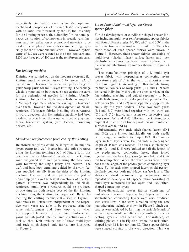
Three-dimensional multi-layer curvilinearspacer fabric
For the development of curvilinear-shaped spacer fab-rics including multi-layer reinforcements, spacer fabricswith four different angles: 0�, 90�, �90�, and 360� in thewarp direction were considered to build up. The sche-matic views of such spacer fabrics were shown inFigure 3. However, these spacer fabrics consisting ofmulti-layer (biaxial inlays) surface layers and tuckstitch-shaped connecting layers were produced withthe new manufacturing techniques shown in Figures 4and 5.
The manufacturing principle of 3-D multi-layerspacer fabric with perpendicular connecting layers(curvature angle of 0� in the warp direction) is illus-trated in Figure 4. According to this manufacturingtechnique, two sets of warp yarns (C-1 and C-2) weredelivered individually through the open carriage of theflat knitting machine and guided separately to bothneedle beds using specially designed warp guides. Twoweft yarns (B-1 and B-2) were separately supplied lat-erally by the yarn feeders. These two weft yarns(B-1 and B-2) were joined together with two warp sets(C-1 and C-2) individually using two respective baseloop yarns (A-1 and A-2) following the knitting tech-nique K-1 to construct two separate biaxial reinforcedsurface layers (a and b).
Subsequently, two tuck stitch-shaped layers (D-1and D-2) were knitted individually on both needlebeds using the knitting technique K-2. Both multi-layer surface layers were knitted until a predesignedlength of 45mm was reached. The tuck stitch-shapedlayers (D-1 and D-2) were knitted to half the length ofthe predesignated connecting layer, then joinedtogether with the base loop yarn (phases 2–4), and knit-ted to completion. When the warp yarns were drawnback to the length of the predesignated connecting layer(phase 5), the tuck stitch-shaped layers could perpen-dicularly connect both multi-layer surface layers. Theabove-mentioned manufacturing sequences wererepeated to develop a 3-D spacer fabric consisting ofmulti-layer reinforced surface layers and tuck stitch-shaped connecting layers.
Three-dimensional spacer fabrics consisting ofmulti-layer (biaxial inlays) surface layers and tuckstitch-shaped connecting layers were also producedwith curvatures in the warp direction using the newmanufacturing technique shown in Figure 5. Such cur-vatures were achieved by knitting the variable length ofsurface layers while simultaneously knitting the con-necting layers on both needle beds. For instance, seeknitting phases 2–4 in Figure 5, where the tuck stitch-shaped layer E1 is longer than E2. These spacer fabricswere shaped curving in the warp direction. This was
3556 Journal of Reinforced Plastics and Composites 29(24)
by guest on January 8, 2016jrp.sagepub.comDownloaded from

Curvature: 0° Curvature: 90°
Curvature:±90° Curvature: 360°
Figure 3. Diagram of 3D spacer fabrics with different curvature angles in the warp direction.
Warp guide
Sinker
Yarn for basefabric
Yarn for base fabric
Biaxialstructure
Reinforcementyarn as tuckstitch (tuck stitchshaped structure)
Knitting technique (K-1) for biaxialstructure
Knitting technique (K-2) for biaxial aswell as tuck stitch shaped structures
Latch needle
Warp yarn
Weft yarn
Figure 1. Knitting technique for multi-layer integration of reinforcing yarns.
C
Reinforcement yarns as biaxial inlays usingthe knitting techniqe K-1
A: base loop yarn; B: weft yarn; C: warp yarn; D: tuck stitch
Reinforcement yarns as tuck stitches usingthe knitting techniqe K-2
C A B D A D
Wales
Course
Figure 2. Arrangements of reinforcement yarns in 2D knit structures.
Abounaim et al. 3557
by guest on January 8, 2016jrp.sagepub.comDownloaded from

accomplished by drawing the warp yarns back to theirfree lengths, which were different for both needle beds.Such curves could be achieved in opposite angles if thetuck stitch-shaped layer E2 is knitted longer than E1 asseen in the knitting phases 2–4. Three-dimensionalmulti-layer spacer fabrics were produced curved inthree different predesignated angles (90�, �90�, and360�) in the warp direction. The spacer fabric withthe curvature angle of �90� could be achieved by knit-ting first a 90� curvature in the warp direction, and thencurving back to the 0� angle on the immediately next.Spacer fabrics with 90� and �90� curvatures were pro-duced by combining both the manufacturing techniquesshown in Figures 4 and 5, whereas spacer fabric with a360�curvature was produced using only themanufacturing technique shown in Figure 5.
Thermoplastic composite using 3D spacer fabric
To fabricate the 3D composite, the laboratory hot-press machine (COLLIN P300 PV, Dr Collin GmbH,Germany) was used to process the 3D multi-layerspacer fabric (curvature 0�). Recently developed and
specially designed mechanical tools11,22 were used forthe 3D thermoplastic molding process. However, fur-ther research is being conducted to develop mechanicaltools for the 3D thermoplastic molding process of theremaining curvilinear spacer fabrics. The combinationof high temperature and high pressure which was estab-lished for 3D thermoplastic consolidation by conduct-ing various experiments11 was used to consolidate the3D spacer fabric into the composite.
Two-dimensional knit fabrics with differentarrangements of reinforcement yarns
For further analysis, 2D fabrics were knitted separatelywith the reinforcement yarns similar to the manner inwhich the U-shaped 3D spacer fabrics were knitted:knit fabrics with reinforcement yarns as multi-layerbiaxial inlays and as tuck stitches. Moreover, thespecifications for the 2D knit fabrics were adjustedto reflect the respective layers of the produced 3Dspacer fabrics. The manufacturing details of these 2Dknit structures are shown in Figures 1 and 2.Additionally, fabric details are presented in Table 1,
a: surface layer on front needle beds, b: surface layer on rare needle bed, c: connecting layer,A-1 & A-2: yarns for base fabrics, B-1 & B-2: weft yarns, C-1 & C-2: warp yarns, D-1 & D-2,reinforcement yarns as tuck stitches, H: distance between connecting layers, L: distancebetween surface layers
Phase-4 Phase-5
Phase-1 Phase-2 Phase-3
HL
b
c
C-1 C-2
A-2A-1
B-2
D-2D-1
B-1
aba
ba ba ba
Withdrawn ofwarp yarns
3D spacer fabric
Figure 4. Manufacturing of 3D multi-layer spacer fabric (curvature 0�).
3558 Journal of Reinforced Plastics and Composites 29(24)
by guest on January 8, 2016jrp.sagepub.comDownloaded from
and Figure 6 represents the 2D knit fabrics andcomposites.
Tensile testing of reinforcement yarns and 2Dknit fabrics
The tensile strengths of yarns and 2D knit fabrics weremeasured on the Zwick Z100 yarn testing machine(Zwick GmbH & Co. KG, Germany). The methodused for assessing the reduction of tensile strength of
reinforcement GF–PP hybrid yarns with different inte-grations was based on measuring the strength before(Tb) and after knitting (Ta), and calculating theirstrength loss (L) as a percentage according to the fol-lowing formula:
L ¼Tb � Ta
Tb
� �� 100%: ð1Þ
The measurement of the yarn breaking force afterknitting could be measured after being carefully
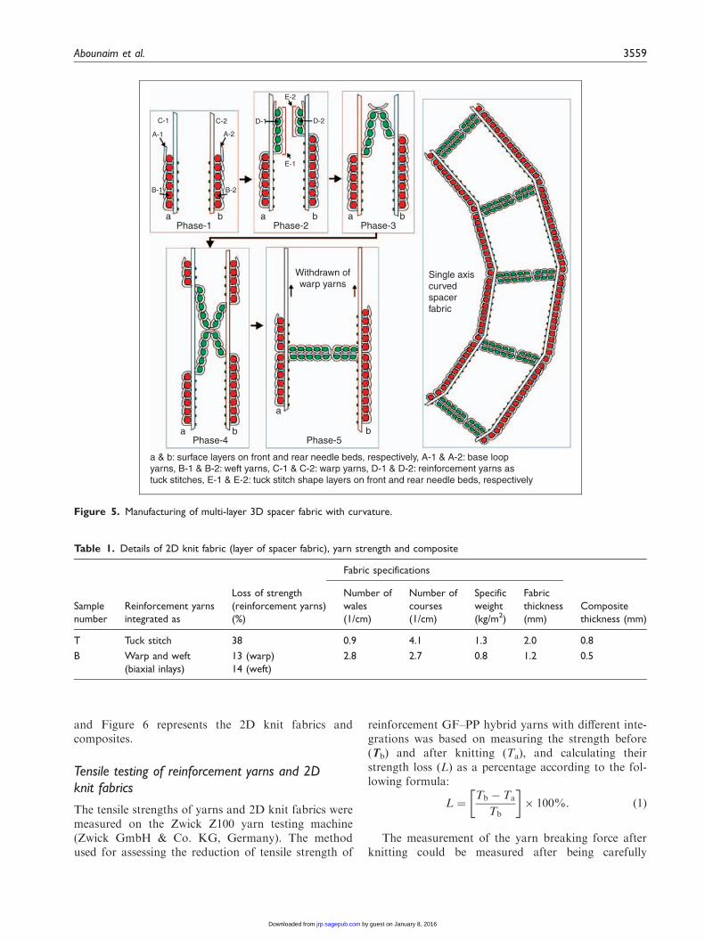
a & b: surface layers on front and rear needle beds, respectively, A-1 & A-2: base loopyarns, B-1 & B-2: weft yarns, C-1 & C-2: warp yarns, D-1 & D-2: reinforcement yarns astuck stitches, E-1 & E-2: tuck stitch shape layers on front and rear needle beds, respectively
Phase-5Phase-4
Phase-1 Phase-2 Phase-3
Single axiscurvedspacerfabric
Withdrawn ofwarp yarns
C-1
a b
a
a
b b
a b a b
C-2
A-2A-1
D-2D-1
E-1
E-2
B-2B-1
Figure 5. Manufacturing of multi-layer 3D spacer fabric with curvature.
Table 1. Details of 2D knit fabric (layer of spacer fabric), yarn strength and composite
Fabric specifications
Sample
number
Reinforcement yarns
integrated as
Loss of strength
(reinforcement yarns)
(%)
Number of
wales
(1/cm)
Number of
courses
(1/cm)
Specific
weight
(kg/m2)
Fabric
thickness
(mm)
Composite
thickness (mm)
T Tuck stitch 38 0.9 4.1 1.3 2.0 0.8
B Warp and weft
(biaxial inlays)
13 (warp)
14 (weft)
2.8 2.7 0.8 1.2 0.5
Abounaim et al. 3559
by guest on January 8, 2016jrp.sagepub.comDownloaded from

unraveled from the 3D spacer fabric (0� curved). Thetensile strengths of the yarns were measured using teststandard DIN EN ISO 2062. Two-dimensional knitfabrics were used to measure the tensile properties fol-lowing the test standards DIN EN ISO 13934-1.
Measuring the mechanical properties of2D composites
Two-dimensional composites were also produced from2D knit fabrics on the laboratory hotpressing machine(COLLIN P300 PV, Dr. Collin GmbH, Germany). Atfirst, knit fabrics were put into the press machine atroom temperature with a pressure of 9 bar. The temper-ature was then raised at the rate of 10�C/min until221�C was reached for melting PP. After 6min at221�C, a pressure of 52 bar was applied (oscillating)and this temperature was kept for 10min. Finally, thetemperature was dropped down to room temperaturekeeping the pressure constant. Table 1 and Figure 6present the details of knit fabrics that were used tofabricate composites. Testing of the tensile and flexuralproperties of the composite plate was also performedon the Zwick Z100 strength testing machine. Themachine uses the four-point loading method for testingthe flexural strengths of the specimens. The testing wascarried out according to the German test standards
DIN EN ISO 527-4 for tensile and DIN EN ISO14125 for flexural strength. The impact tests were car-ried out with the aid of a pendulum arm type impacttester, which functions based on the principle ofCharpy impact test technique. Testing was carried outat the Institute of Lightweight Engineering andPolymer Technology (ILK) at TU Dresden,Germany. Standard methods of sampling and testingwere applied as stated in DIN EN ISO 179-2. All thetest specimens in the wales and course directions ofknit fabrics as well as of composites were designatedby 0� and 90�, respectively.
Results and discussion
Curvilinear 3D multi-layer spacer fabrics and3D thermoplastic composite
Figure 7 shows the flat knitted 3D multi-layer spacerfabrics with different curvatures in the warp directionusing GF–PP hybrid yarns, along with the example ofthermoplastic composite made from 0�-curved 3Dmulti-layer spacer fabric. The fabric specifications ofindividual layers of these spacer fabrics are presentedin Table 1. The distance between the surface layers ofall spacer fabrics was designed as 30mm. However, thelength between the two neighboring connecting layers is
Knitted fabric – type B
Composite – type B
A: base loop yarn, B & C: weft & warp inlays, D: tuck sitich, 0°: walesdirection, 90°: course direction
Knitted fabric – type T
Composite – type T
A
A
D
B
C0°
90°
Figure 6. Two-dimensional knit fabrics and composites.
3560 Journal of Reinforced Plastics and Composites 29(24)
by guest on January 8, 2016jrp.sagepub.comDownloaded from

45mm for spacer fabrics with 0� curvature, whereas it isdissimilar for both surface layers of the spacer fabricswith the curvature angles of 90�, �90�, and 360� due toinclined joining between the surface layers by the con-nection layers.
Tensile properties of reinforcement yarns and2D knit fabrics
The integration of reinforcement yarns as biaxial inlays(warp and weft yarns as multi-layer) and as tuck stitchesinto 3D spacer fabric (0� curved) has a clear effect onthe tensile properties of the hybrid yarns as well as those
of the knit fabrics. The stress–strain curves are pre-sented in Figure 8(a) and (c), whereas Figure 8(b)–(d)shows the tensile strengths. The maximum loss of yarnstrength was recorded as 45% for tuck stitches, but notmore than 5–10% for biaxial inlays (warp and weftyarns). Consequently, knit fabric with reinforcementyarns as biaxial inlays shows improved tensile proper-ties with equally reduced elongation in both course andwales directions. Nevertheless, knit fabrics with tuckstitches also have improved tensile strength in thecourse direction similar to the biaxial inlays. However,such tensile strength was recorded after a considerableamount of extension. In the case of reinforcement
Curvature: 0° Curvature: 90°
Curvature: 360°Curvature: ±90°3D multi-layer spacer fabrics
3D composite using 0°– curved spacer fabric
30 mm 45 mm
Figure 7. Three-dimensional textile preforms and consolidated 3D composite.
Abounaim et al. 3561
by guest on January 8, 2016jrp.sagepub.comDownloaded from
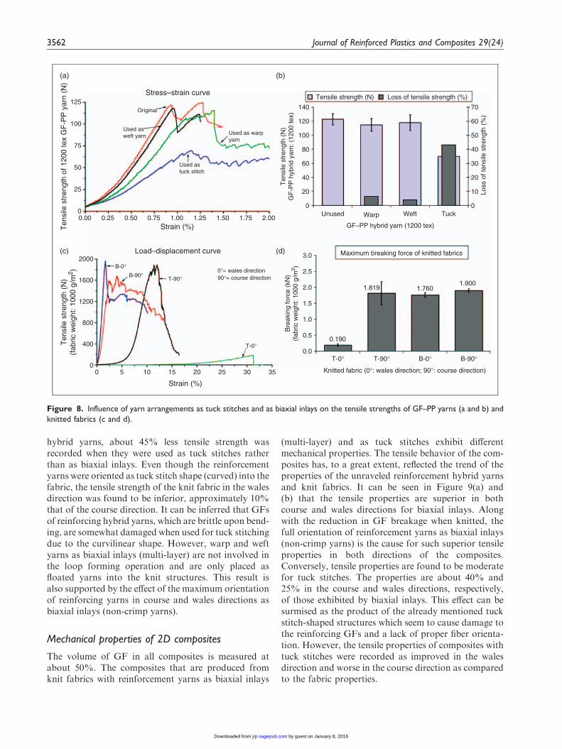
hybrid yarns, about 45% less tensile strength wasrecorded when they were used as tuck stitches ratherthan as biaxial inlays. Even though the reinforcementyarns were oriented as tuck stitch shape (curved) into thefabric, the tensile strength of the knit fabric in the walesdirection was found to be inferior, approximately 10%that of the course direction. It can be inferred that GFsof reinforcing hybrid yarns, which are brittle upon bend-ing, are somewhat damaged when used for tuck stitchingdue to the curvilinear shape. However, warp and weftyarns as biaxial inlays (multi-layer) are not involved inthe loop forming operation and are only placed asfloated yarns into the knit structures. This result isalso supported by the effect of the maximum orientationof reinforcing yarns in course and wales directions asbiaxial inlays (non-crimp yarns).
Mechanical properties of 2D composites
The volume of GF in all composites is measured atabout 50%. The composites that are produced fromknit fabrics with reinforcement yarns as biaxial inlays
(multi-layer) and as tuck stitches exhibit differentmechanical properties. The tensile behavior of the com-posites has, to a great extent, reflected the trend of theproperties of the unraveled reinforcement hybrid yarnsand knit fabrics. It can be seen in Figure 9(a) and(b) that the tensile properties are superior in bothcourse and wales directions for biaxial inlays. Alongwith the reduction in GF breakage when knitted, thefull orientation of reinforcement yarns as biaxial inlays(non-crimp yarns) is the cause for such superior tensileproperties in both directions of the composites.Conversely, tensile properties are found to be moderatefor tuck stitches. The properties are about 40% and25% in the course and wales directions, respectively,of those exhibited by biaxial inlays. This effect can besurmised as the product of the already mentioned tuckstitch-shaped structures which seem to cause damage tothe reinforcing GFs and a lack of proper fiber orienta-tion. However, the tensile properties of composites withtuck stitches were recorded as improved in the walesdirection and worse in the course direction as comparedto the fabric properties.
125140
120
100
80
60
40
20
0
70
60
50
40
30
20
10
0
Loss
of t
ensi
le s
tren
gth
(%)
100
75
50
25
0
2000
1600
1200
800
400
0
0.00 0.25 0.50
B-0°
T-0°
T-90°0°= wales direction 90°= course direction B-90°
T-90°T-0° B-90°B-0°
0.75 1.00Strain (%)
Load–displacement curve
Stress–strain curve
Used astuck stitch
Used as warpyarn
Used asweft yarn
Original
Ten
sile
str
engt
h of
120
0 te
x G
F-P
P y
arn
(N)
Ten
sile
str
engt
h (N
)G
F-P
P h
ybrid
yar
n: (
1200
tex)
1.25 1.50 1.75 2.00
Strain (%)
Knitted fabric (0°: wales direction; 90°: course direction)
Maximum breaking force of knitted fabrics
GF–PP hybrid yarn (1200 tex)
Unused
Tensile strength (N) Loss of tensile strength (%)
WeftWarp Tuck
0.190
1.819
3.0
2.5
2.0
1.5
1.0
0.5
0.0
1.7601.900
0 5 10 15 20 25 30 35
Ten
sile
str
engt
h (N
)(f
abric
wei
ght:
1000
g/m
2 )
Bre
akin
g fo
rce
(kN
)(f
abric
wei
ght:
1000
g/m
2 )
(a) (b)
(c) (d)
Figure 8. Influence of yarn arrangements as tuck stitches and as biaxial inlays on the tensile strengths of GF–PP yarns (a and b) and
knitted fabrics (c and d).
3562 Journal of Reinforced Plastics and Composites 29(24)
by guest on January 8, 2016jrp.sagepub.comDownloaded from

Keeping in view the analysis of flexural propertiesfrom Figure 9(c) and (d), the overall comparison of theknit structures can be ranked as most advantageous forthe biaxial inlays and least advantageous for the tuckstitches. The flexural properties in course and walesdirections of composites with tuck stitches differ by35% and 50%, respectively, as compared to biaxialinlays. These effects are endorsed by the already
mentioned combined effect of orientation and damageof reinforcement GF, where the most improved prop-erties are in filament-oriented course and wales direc-tions of biaxial inlays.
On the other hand, the results after impact testing donot follow the trend of tensile and flexural testing,which can be seen in Figure 9(e) and (f). The maximumimpact strength and energy absorption were recorded
0°= wales direction 90°= course direction
0°= wales direction 90°= course direction
0°= wales direction 90°= course direction
Ten
sile
str
engt
h (M
Pa)
Ten
sile
str
eng
th (
MP
a)
Strain (%)
B-0°T-0° T-90° B-90°
B-0°
T-0°
T-90°
B-90°
B-0°
T-0°T-90°
B-90°
B-0°
T-0°
T-90°
B-90°
B-0°T-0° T-90° B-90°
B-0°T-0° T-90° B-90°
Load–displacement curve
Contact force–displacement curve
Displacement (mm)
Displacement (mm)
Stress–strain curve
0 1 2 3 4 5 6
0 3 6 9 12 15
0 4 8 12 16 20
350
300
250
150
200
100
50
0
350
300
250
150
200
100
50
0
Fle
xura
l str
engt
h (M
Pa)
Fle
xura
l str
eng
th (
MP
a)Im
pac
t st
ren
gth
(kJ
/m2 )
Con
tact
forc
e (k
N)
300
250
150
200
100
50
0
300
250
150
200
100
50
0
250
150
200
100
50
0
1.0
0.8
0.4
0.6
0.2
0.0
36
30
24
18
12
6
0
20
16
12
8
4
0
10
8
6
4
2
0
E–M
od
ulu
s (G
Pa)
E–M
od
ulu
s (G
Pa)
En
erg
y ab
sorp
tio
n (
J)
Tensile strength Tensile modulus
Flexural strength Flexural modulus
Impact strength Energy absorption
(a) (b)
(c) (d)
(e) (f)
Figure 9. Mechanical properties of 2D knit composites with different reinforcements (a and b: tensile; c and d: flexural; and e and f:
impact properties).
Abounaim et al. 3563
by guest on January 8, 2016jrp.sagepub.comDownloaded from
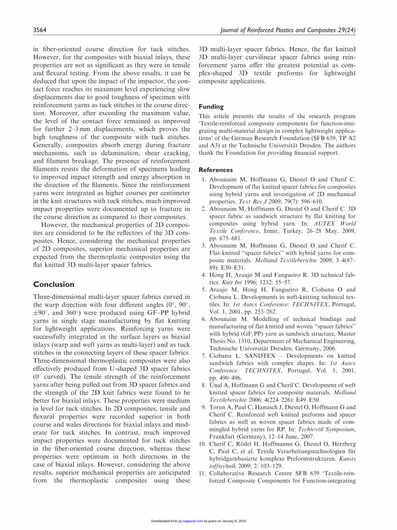
in fiber-oriented course direction for tuck stitches.However, for the composites with biaxial inlays, theseproperties are not as significant as they were in tensileand flexural testing. From the above results, it can bededuced that upon the impact of the impactor, the con-tact force reaches its maximum level experiencing slowdisplacements due to good toughness of specimen withreinforcement yarns as tuck stitches in the course direc-tion. Moreover, after exceeding the maximum value,the level of the contact force remained as improvedfor further 2–3mm displacements, which proves thehigh toughness of the composite with tuck stitches.Generally, composites absorb energy during fracturemechanisms, such as delamination, shear cracking,and filament breakage. The presence of reinforcementfilaments resists the deformation of specimens leadingto improved impact strength and energy absorption inthe direction of the filaments. Since the reinforcementyarns were integrated as higher courses per centimeterin the knit structures with tuck stitches, much improvedimpact properties were documented up to fracture inthe course direction as compared to their composites.
However, the mechanical properties of 2D compos-ites are considered to be the reflectors of the 3D com-posites. Hence, considering the mechanical propertiesof 2D composites, superior mechanical properties areexpected from the thermoplastic composites using theflat knitted 3D multi-layer spacer fabrics.
Conclusion
Three-dimensional multi-layer spacer fabrics curved inthe warp direction with four different angles (0�, 90�,�90�, and 360�) were produced using GF–PP hybridyarns in single stage manufacturing by flat knittingfor lightweight applications. Reinforcing yarns weresuccessfully integrated in the surface layers as biaxialinlays (warp and weft yarns as multi-layer) and as tuckstitches in the connecting layers of these spacer fabrics.Three-dimensional thermoplastic composites were alsoeffectively produced from U-shaped 3D spacer fabrics(0� curved). The tensile strength of the reinforcementyarns after being pulled out from 3D spacer fabrics andthe strength of the 2D knit fabrics were found to bebetter for biaxial inlays. These properties were mediumin level for tuck stitches. In 2D composites, tensile andflexural properties were recorded superior in bothcourse and wales directions for biaxial inlays and mod-erate for tuck stitches. In contrast, much improvedimpact properties were documented for tuck stitchesin the fiber-oriented course direction, whereas theseproperties were optimum in both directions in thecase of biaxial inlays. However, considering the aboveresults, superior mechanical properties are anticipatedfrom the thermoplastic composites using these
3D multi-layer spacer fabrics. Hence, the flat knitted3D multi-layer curvilinear spacer fabrics using rein-forcement yarns offer the greatest potential as com-plex-shaped 3D textile preforms for lightweightcomposite applications.
Funding
This article presents the results of the research program‘Textile-reinforced composite components for function-inte-
grating multi-material design in complex lightweight applica-tions’ of the German Research Foundation (SFB 639, TP A2and A3) at the Technische Universitat Dresden. The authorsthank the Foundation for providing financial support.
References
1. Abounaim M, Hoffmann G, Diestel O and Cherif C.
Development of flat knitted spacer fabrics for composites
using hybrid yarns and investigation of 2D mechanical
properties. Text Res J 2009; 79(7): 596–610.2. Abounaim M, Hoffmann G, Diestel O and Cherif C. 3D
spacer fabric as sandwich structure by flat knitting for
composites using hybrid yarn. In: AUTEX World
Textile Conference, Izmir, Turkey, 26–28 May, 2009,
pp. 675–681.3. Abounaim M, Hoffmann G, Diestel O and Cherif C.
Flat-knitted ‘‘spacer fabrics’’ with hybrid yarns for com-
posite materials. Melliand Textileberichte 2009; 3–4(87–
89): E30–E31.4. Hong H, Araujo M and Fangueiro R. 3D technical fab-
rics. Knit Int 1996; 1232: 55–57.5. Araujo M, Hong H, Fangueiro R, Ciobanu O and
Ciobanu L. Developments in weft-knitting technical tex-
tiles. In: 1st Autex Conference: TECHNITEX, Portugal,
Vol. 1, 2001, pp. 253–262.6. Abounaim M. Modelling of technical bindings and
manufacturing of flat knitted and woven ‘‘spacer fabrics’’
with hybrid (GF/PP) yarn as sandwich structure, Master
Thesis No. 1310, Department of Mechanical Engineering,
Technische Universitat Dresden, Germany, 2006.7. Ciobanu L. SANDTEX – Developments on knitted
sandwich fabrics with complex shapes. In: 1st Autex
Conference: TECHNITEX, Portugal, Vol. 1, 2001,
pp. 490–496.8. Unal A, Hoffmann G and Cherif C. Development of weft
knitted spacer fabrics for composite materials. Melliand
Textileberichte 2006; 4(224–226): E49–E50.
9. Torun A, Paul C, Hanusch J, Diestel O, Hoffmann G and
Cherif C. Reinforced weft knitted preforms and spacer
fabrics as well as woven spacer fabrics made of com-
mingled hybrid yarns for RP. In: Techtextil Symposium,
Frankfurt (Germany), 12–14 June, 2007.
10. Cherif C, Rodel H, Hoffmannn G, Diestel O, Herzberg
C, Paul C, et al. Textile Verarbeitungstechnologien fur
hybridgarnbasierte komplexe Preformstrukturen. Kunsts
tofftechnik 2009; 2: 103–129.11. Collaborative Research Centre SFB 639 ‘Textile-rein-
forced Composite Components for Function-integrating
3564 Journal of Reinforced Plastics and Composites 29(24)
by guest on January 8, 2016jrp.sagepub.comDownloaded from

Multi-material Design in Complex LightweightApplications’, Technische Universitat Dresden, http://www.tu-dresden.de/mw/ilk/sfb639/sfb_en.html, Germany
(accessedMarch 2010).12. Badawi SSAM. Development of the weaving machine
and 3D woven spacer fabric structures for lightweightcomposites materials, PhD Thesis, Department of
Mechanical Engineering, Technische Universitat Dresden,Germany, 2007.
13. Alagirusamy R and Ogale V. Commingled and air jet-
textured hybrid yarns for thermoplastic composites.J Ind Text 2004; 33: 223–243.
14. Fujita A, Maekawa Z and Hamada H. Mechanical
behaviour and fracture mechanism of thermoplastic com-posites with commingling yarn. J Reinf Plast Compos1993; 12: 156–172.
15. Dev V, Swarna A and Madhusoothanan M. Mechanicalproperties of knitted composites using glass ply yarns.J Reinf Plast Compos 2005; 25: 1425–1435.
16. Gommers B, Verpoest I and Houtte V. Analysis of
knitted fabric reinforced composites: Part 1.
Fibre orientation distribution. Composites Part A 1998;
29A: 1579–1588.
17. Padaki N, Alagirusamy R and Sugun B. Knitted pre-
forms for composite application. J Ind Text 2006; 35(4):
295–321.18. Hu H and Zhu M. A study of the degree of breakage of
glass filament yarns during the weft knitting process.
AUTEX Res J 2005; 5(3): 141–148.19. Lau K and Dias T. Knittability of high-modulus yarns.
J Text Inst 1994; 85(2): 173–190.20. Savci S, Curiskis J and Pailthorpe M. Knittability of glass
fiber weft-knitted preforms for composites. Text Res J
2001; 71(1): 15–21.
21. Rios C, Ogin S, Lekakou C and Leong K. A study of
damage development in a weft knitted fabric reinforced
composite: Part 1. Experiments using model sandwich
laminates. Composites Part A 2007; 38: 1773–1793.22. Lin S, Modler KH and Hanke U. The application of
mechanisms in producing textile-reinforced thermoplastic
composite. Mach Des Res 2008; 24: 380–384.
Abounaim et al. 3565
by guest on January 8, 2016jrp.sagepub.comDownloaded from