The Effect of Piezoelectric Fiber Rosette Configurations ...

Original Article
Effect of fiber densities on impactproperties of biaxial warp-knittedtextile composites
O Demircan1,2, C Yilmaz1, ES Kocaman1, S Tang3, H Hamada3
and M Yildiz1
Abstract
In this study, an appropriate fabric weight content controlled by the density of the warp and weft fibers is determined for
biaxial warp-knitted composites referring to mechanical test results. Six different types of composite panel with two
different fabric weights (813 and 1187 gr/m2) and with three different stacking sequences [90we/0wa/90we/0wa]s, [90wa/
0we/90wa/0we]s, and [90wa/0we/90we/0wa]s are fabricated by using Resin Transfer Molding method. Having produced
composite panels, drop weight impact tests are conducted on specimens. Microstructural characterization of impact
tested materials is performed using optical microscope. The results of this study reveal that composites with biaxial
warp-knitted preforms with lower weft and warp fiber densities (thin-ply) could absorb higher impact energies compared
to those with higher weft and warp fiber densities (thick-ply).
Keywords
Textile composites, impact behavior, knitting
Introduction
Due to their high specific strength and stiffness, com-posite materials are valuable structural materials inengineering applications. Some fields benefiting fromthe qualities of composites include aerospace, automo-tive, wind energy, and civil infrastructure. The mechan-ical properties of composites can be tailored throughusing various forms of reinforcements. Knittedcomposites are generally considered to have inferiormechanical properties due to their highly looped struc-ture and low fiber volume fraction.1 In order toimprove the mechanical properties, such as strengthand stiffness, of warp-knitted fabric, straight yarnsboth in weft and warp directions can be integrated.These types of reinforcements are called biaxial warp-knitted (BWK) structures. Weft and warp yarn layersare held together by stitching yarns in BWK fabrics.Reinforcing yarns, e.g., glass or aramid fibers, can beused within all yarn systems.
Mechanical properties of knitted fabric compositeswere investigated by Hamada et al.2 They conductedtensile, three-point bending and plate-bending tests on
knitted composites. Mechanical properties, such as ten-sile, three-point bending, and impact, of textile-insertedPP/PP knitted composites produced using injection-compression molding were reported by Khondkeret al.3 The tensile properties of weft-knitted compositesfor energy absorption were studied by Xue et al.4
They described correlations between fabric structure(e.g., loop height and width, number of wale or
1Faculty of Engineering and Natural Sciences, Advanced Composites and
Polymer Processing Laboratory (AC2PL), Sabanci University, Istanbul,
Turkey2Materials Science and Engineering Department, Faculty of Engineering,
Ondokuz Mayıs University, Samsun, Turkey3Department of Advanced Fibro-Science, Graduate School of Science and
Technology, Kyoto Institute of Technology, Kyoto, Japan
Corresponding author:
M Yildiz, Faculty of Engineering and Natural Sciences, Advanced
Composites and Polymer Processing Laboratory (AC2PL), Sabanci
University, Orhanli-Tuzla, Istanbul 34196, Turkey.
Email: [email protected]
Journal of Reinforced Plastics
and Composites
2015, Vol. 34(16) 1287–1297
! The Author(s) 2015
Reprints and permissions:
sagepub.co.uk/journalsPermissions.nav
DOI: 10.1177/0731684415577985
jrp.sagepub.com
at Sabanci Universitesi on December 7, 2015jrp.sagepub.comDownloaded from

course per unit length, etc.), matrix damage, and mater-ial properties.
The impact properties of weft-knitted fabricreinforcement composites were investigated by severalresearchers.5–8 In comparison to composites manufac-tured from a single layer of fabric, knitted compositeswith an increased number of fabric layers demonstratedimproved impact damage resistance and fracturetoughness.9–11 Impact properties of three-dimensional(3-D) biaxial weft-knitted composites were studiedboth numerically and experimentally by Li et al.12
They pointed out that energy absorption increasedwith the increase of impact velocity. Hufenbachet al.13 studied hybrid 3-D biaxial weft-knitted rein-forced composites for impact applications. They com-pared impact properties of composites with biaxialweft-knitted preforms consisting of different fiber com-binations, such as glass-glass-glass, glass-glass-aramid,and glass-glass-polyethylene. Demircan et al. have alsoinvestigated the biaxial weft-knitted composites madeof glass-glass-glass fibers and indicated that the fabricstructure improves the impact properties of compositesnotably due to the presence of 0� and 90� fiber insidethe preform. Based on the results of plate-bendingimpact test,14 they showed that the total absorbedimpact energy of the biaxial weft-knitted composites(46.0 J) is three times more than that of the glassweft-knitted fabric composites without biaxial fibers(13.9 J).15 This increase can be attributed to the factthat biaxial fibers facilitate global load distributionthereby making it difficult for the impactor to penetratethrough the thickness of the plane. Due to the simili-tude between the fabric structures of biaxial weft andwarp-knitted composites, BWK fabric structure shouldalso present improved impact performance due to theabove discussed mechanism.
The stacking sequences can affect mechanical prop-erties of composites. Khashaba et al.16 reported failureand reliability analysis of pinned-joints compositelaminates with different stacking sequence. They stu-died four configurations such as [0/90]2s, [15/�75]2s,[30/�60]2s, and [45/�45]2s and reported that specimenswith [0/90]2s stacking sequence had the maximum fail-ure displacement and ultimate stress compared to theother stacking sequences from bearing tests. Aktas andDirikolu17 studied the effect of stacking sequence ofcarbon epoxy composite laminates on pinned-jointstrength through considering two configurations,namely [0/45/�45/90]s and [90/45/�45/0]s. They foundthat the [90/45/�45/0]s orientation had higher strengthfrom bearing tests compared to the [0/45/�45/90]s.Park18 reported the effects of stacking sequenceand clamping force on the bearing strengths of mech-anically fastened joints in composite laminates throughstudying two orthotropic ([906/06]s and [06/906]s) and
three quasi-isotropic ([903/�453/03]s, [903/03/�453]s,and [03/�453/903]s) laminate lay-up configurations. Hefound that the orthotropic composite laminates hadalmost the same bearing strengths, while [906/06]s lay-up had the delaminations bearing strength nearly twotimes stronger than [06/906]s stacking sequence.According to the results of delaminations bearing fail-ure, the stacking sequence of the lay-up [906/06]s with90� layers on the surface was more advantageous thanthe lay-up [06/906]s with 0� layers. He also reportedthat the higher ultimate bearing strengths for quasi-isotropic laminates were [903/�453/03]s, [903/03/�453]s,and [03/�453/903]s. Mattsson et al.19 studied damage innon-crimp-fabric (NCF) composites under tension.They found that stacking sequence with [0/90/0/90]slay-up had much larger elastic modulus reductionthan that with [90/0/90/0]s lay-up.
The fiber densities (thin and thick plies) can affectmechanical properties of composites. Tsai et al.20 inves-tigated thin-ply composites and found that laminatemade of thin-plies showed remarkable resistance tomicrocracking, delaminations, and fatigue loading.Sihn et al.21 performed experimental studies on thin-ply laminated composites and found that the thin-plycomposites could suppress the microcracking anddelamination damages without special resin or 3-Dreinforcements. Guillamet et al.22 reported damageoccurrence at the edges of NCF thin-ply laminatesunder off-axis uniaxial loading. They found that thethick region of composites was the critical region forthe occurrence of the damage, whereas the thin regionof the composites experienced damage mechanism(delaminations), which are delayed or suppressed.Yokozeki et al.23 experimentally investigated thestrength and damage resistance properties of thin-plycarbon fiber/toughened epoxy laminates and reportedthat composites with thin-ply prepregs compared tostandard prepregs had superior characteristics for ten-sion, tension–tension fatigue, non-hole and open-holecompression strengths, and compression strength afterimpact loading tests. Amacher et al.24,25 studied thin-ply composites and noted that the uniaxial tension,open-hole compression, and open-hole tensile fatiguetests on quasi-isotropic [45�/90�/�45�/0�]ns laminatesshow significant improvements in terms of the onsetof damage, and in some cases ultimate strength upondecreasing the ply thickness. Tan et al.26,27 studied theeffect of stitch density and stitch thread thickness oncompression after impact strength and the response ofstitched composites. They obtained increased compres-sion after impact strength for laminates with largerstitch thread thickness.
In literature, one may find quite many excellent con-tributions reporting on the mechanical properties ofthin and thick plies composites, some of which have
1288 Journal of Reinforced Plastics and Composites 34(16)
at Sabanci Universitesi on December 7, 2015jrp.sagepub.comDownloaded from

been cited above. However, to our best knowledge,there is no study dedicated to address the effect offiber thickness and fabric stacking sequences onthe mechanical properties of BWK composites concur-rently. Moreover, only a few studies are there about theimpact properties of knitting composites with differentfiber densities and stacking sequence combinations. Theaim of study is to determine appropriate fabric weightcontent controlled by the density of the warp and weftfibers for BWK thin and thick plied composites refer-ring to impact test results. To this end, the effect of fiberdensities and fabric stacking sequences on impact prop-erties of BWK thin and thick plied composites isreported within this study. The results of impact testsmight be used to design the new textile preforms duringthe development of different composite materials. Forexample, due to the higher impact energy absorptioncapacity of the BWK reinforced composites, which willbe addressed in detail subsequently, BWK compositescan specifically be considered for ballistic applications.
Experimental procedure
Composites constituents
The BWK fabrics with several fabric weights (813 gr/m2
(G3) and 1187 gr/m2 (G5)) were produced on warpknitting machine of Metyx Composites Ltd., Turkey.Figure 1 depicts the fabricated BWK reinforcementfabric. E-glass fibers were used as biaxial warp andweft fibers and stitch fiber materials. Epoxy resinsystem (LY 564 resin, XB 3403 hardener byHuntsman) was used as matrix material. Table 1
shows the parameters of the E-glass fiber reinforce-ments. The BWK composite with the fabric weightsof 813 gr/m2 and 1187 gr/m2 is respectively referred toas thin-ply and thick-ply.
Fabrication method
Four-layer BWK composites have been produced usingResin Transfer Molding (RTM) method with three dif-ferent stacking sequences, namely, [90we/0wa/90we/0wa]s,[90wa/0we/90wa/0we]s, and [90wa/0we/90we/0wa]s. Here, 0�
and 90� fiber orientation in the preforms respectivelyindicate directions parallel and perpendicular to thelength of the composite plate which is aligned withthe flow direction of the resin, while warp and weftfibers are denoted with the subscripts of ‘‘wa’’ and‘‘we’’ correspondingly. Here, within the preforms,0� fiber orientation indicates the warp direction,whereas the 90� denotes the weft direction. In the fol-lowing, the designation G and B is used to refer tofabric type and stacking sequence, respectively. Here,the G3 and G5 are correspondingly the fabric codes forLT800 E 10A 0/90 (thin-ply) and LT1200E 05B 0/90(thick-ply), where 10 A and 05 B in fabric designationstands for the number of stitch per inch, which is 10 and5 for the fabrics in question correspondingly. Becausethe fiber densities in warp and weft directions are notthe same, we have prepared composites with three dif-ferent stacking sequences using each type of fabric,where B1, B2, and B3 respectively represent the first,the second, and the third type of stacking sequences,[90we/0wa/90we/0wa]s, [90wa/0we/90wa/0we]s, and [90wa/0we/90we/0wa]s. Figure 2 yields the schematic drawing
813 gr/m2 (G3) 1187 gr/m2 (G5)
Warp (wale)= 0o
Weft (course)= 90o
Warp fibers Warp fibers
Wef
tfib
ers
Wef
tfib
ers
Stit
ch fi
bers
Stit
ch fi
bers
0.5 mm 0.5 mm
(a) (b)
Figure 1. Biaxial warp-knitted reinforcement fabrics.
Demircan et al. 1289
at Sabanci Universitesi on December 7, 2015jrp.sagepub.comDownloaded from

for three different stacking sequences. The total volumefractions of composite plates are about 45%.Composite volume fractions are found out by perform-ing burn-out tests. Table 2 lists the volume fraction ofmanufactured composites.
The RTM method can produce high quality nearnet-shape parts with high fiber volume fractions, twohigh-quality surfaces, and requiring little post process-ing in a fully contained system that eliminates humanoperator exposure to chemicals and reduces the chance
Table 1. Parameters of the biaxial warp-knitted (BWK) fabric reinforcements.
E glass samples
0� (warp)
fibers, Tex
90� (weft)
fibers, Tex
Area weight
of 0� warp
fibers (gr/m2)
Area weight
of 90� weft
fibers (gr/m2)
Area weight
of stitch
fibers (gr/m2)
Fabric weight
(warp, weft and
stitch fibers)
(gr/m2)
LT800 E 10A 0/90 (G3) 900 + 1200¼ 2100 900 413 390 10 813
LT1200E 05B 0/90 (G5) 2400 1200 566 614 7 1187
Figure 2. The schematic drawing for three different stacking sequences, namely, (a) B1, (b) B2, and (c) B3. Here, l, w, and t indicate
the length, width, and the thickness of the manufactured composite plate.
Table 2. Fiber volume fraction and thickness of composites.
Specimens (composites)
Number
of layers Weft Vf (%) Warp Vf (%) Stitch Vf (%) Total Vf (%)
Thickness
(mm)
G3-B1 4 20.3 21.5 0.52 42.4 2.89
G3-B2 4 20.9 22.1 0.53 43.5 2.85
G3-B3 4 22.6 23.9 0.58 47.1 2.74
G5-B1 4 23.7 21.8 0.27 45.8 4.03
G5-B2 4 25.0 23.0 0.30 48.3 3.81
G5-B3 4 24.4 22.4 0.28 47.1 3.91
1290 Journal of Reinforced Plastics and Composites 34(16)
at Sabanci Universitesi on December 7, 2015jrp.sagepub.comDownloaded from

of human error. For these reasons, RTM has beenselected to produce specimens for this study. In orderto compare the specimens among each other, the fibervolume fraction of composites is kept constant by vary-ing specimen thickness. The depth of the RTM moldcavity or equivalently the composite plate thickness iscontrolled through using steel plates of different thick-ness. The RTM apparatus is used to produce flat panels(620mm� 320mm) with different thickness. The man-ufactured panels undergo an initial cure at 65�C for24 h with a post cure at 80�C for 24 h.
Mechanical characterization
The schematic drawings of drop weight impact test set-up are shown in Figure 3(a) to (b). The impact damagesare inflicted on different specimens in a drop weight testusing universal testing machine type Dynatup 9250HV,Instron. The drop weight is used as an impactor for thetests. The boundary of the impact specimens is clampedon all sides by a rectangular steel plate with 76mmdiameter circular hole. The center of the specimenwas impacted by a striker with a narrow hemisphericalindenter of 12.9mm diameter. The arrangement inimpact tests was intended to prevent any motion ofthe plate boundary, both in-plane and out-of-plane.
The weight of the impactor and incident impactenergy are 6451 g and 44 J for the impact tests. Thevalue of the utilized impact energy was chosen basedon the experience gained during our previous dropweight impact test experiments on biaxial weft-knittedcomposites with 2.9mm thickness.14 If relatively lowimpact energy was applied to the specimens, the impac-tor would not be able to inflict the required damage onthe specimens with the thicknesses of 3–4mm. To beable to have a consistent experimental condition for allspecimens, the single impact energy was used for all
specimens regardless of their thickness. The compositecoupons have a nominal dimension of 100� 100mm.The impact test measurements are performed at ambi-ent conditions of 23� 2�C and 50� 5% relative humid-ity. Following the relevant literature,28–31 the impacttests were conducted on a single sample for each typeof composite panel.
Results and discussions
Microstructural observation of as-fabricatedcomposites
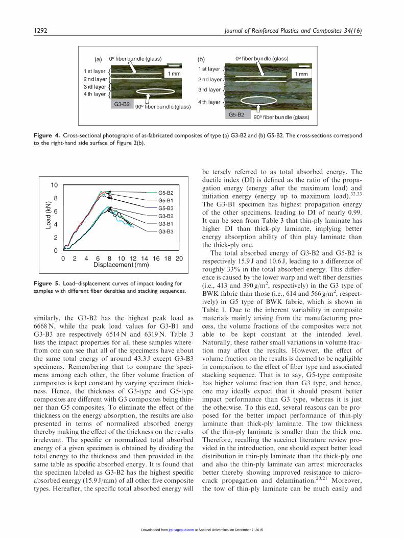
The thickness-wise cross-sectional photographs of as-fabricated composites are shown in Figure 4(a) to (b).It can be seen that there are no voids in cross-section ofthe as-fabricated composites indicating the productionof high-quality composites for this study. However, thevoids seen in the fracture area of impact tested speci-mens (Figure 7) are the entrapped air bubbles createdas a result of pouring the resin into the fracture area toprepare specimens for microstructural observation.
Impact properties of composites
Impact resistance is an important property for compar-ing the mechanical performance of composite samples.In literature, high energy absorption of the knittedcomposites due to the loop structure was reported.Figure 5 shows the load–displacement curves of sam-ples with different fiber densities and stackingsequences, subjected to impact loading.
For the fabric type of G5, the highest peak load isrecorded for the G5-B2 as 9008N, the G5-B1 hasslightly lower peak load as 8975N than the G5-B2,and the lowest peak load belongs to the G5-B3 withthe value of 8451N. As for the fabric type of G3,
12 9 mm
Clamped boundry Specimen
Pneumatic clamp
Impactor
12.9 mm
76 mmSpecimen
100 mm
100 mm
100 mm
100 mm
76 mm
(a) (b)
Figure 3. Schematic drawings of drop weight impact test set-up: (a) top view and (b) side view.
Demircan et al. 1291
at Sabanci Universitesi on December 7, 2015jrp.sagepub.comDownloaded from
similarly, the G3-B2 has the highest peak load as6668N, while the peak load values for G3-B1 andG3-B3 are respectively 6514N and 6319N. Table 3lists the impact properties for all these samples where-from one can see that all of the specimens have aboutthe same total energy of around 43.3 J except G3-B3specimens. Remembering that to compare the speci-mens among each other, the fiber volume fraction ofcomposites is kept constant by varying specimen thick-ness. Hence, the thickness of G3-type and G5-typecomposites are different with G3 composites being thin-ner than G5 composites. To eliminate the effect of thethickness on the energy absorption, the results are alsopresented in terms of normalized absorbed energythereby making the effect of the thickness on the resultsirrelevant. The specific or normalized total absorbedenergy of a given specimen is obtained by dividing thetotal energy to the thickness and then provided in thesame table as specific absorbed energy. It is found thatthe specimen labeled as G3-B2 has the highest specificabsorbed energy (15.9 J/mm) of all other five compositetypes. Hereafter, the specific total absorbed energy will
be tersely referred to as total absorbed energy. Theductile index (DI) is defined as the ratio of the propa-gation energy (energy after the maximum load) andinitiation energy (energy up to maximum load).32,33
The G3-B1 specimen has highest propagation energyof the other specimens, leading to DI of nearly 0.99.It can be seen from Table 3 that thin-ply laminate hashigher DI than thick-ply laminate, implying betterenergy absorption ability of thin play laminate thanthe thick-ply one.
The total absorbed energy of G3-B2 and G5-B2 isrespectively 15.9 J and 10.6 J, leading to a difference ofroughly 33% in the total absorbed energy. This differ-ence is caused by the lower warp and weft fiber densities(i.e., 413 and 390 g/m2, respectively) in the G3 type ofBWK fabric than those (i.e., 614 and 566 g/m2, respect-ively) in G5 type of BWK fabric, which is shown inTable 1. Due to the inherent variability in compositematerials mainly arising from the manufacturing pro-cess, the volume fractions of the composites were notable to be kept constant at the intended level.Naturally, these rather small variations in volume frac-tion may affect the results. However, the effect ofvolume fraction on the results is deemed to be negligiblein comparison to the effect of fiber type and associatedstacking sequence. That is to say, G5-type compositehas higher volume fraction than G3 type, and hence,one may ideally expect that it should present betterimpact performance than G3 type, whereas it is justthe otherwise. To this end, several reasons can be pro-posed for the better impact performance of thin-plylaminate than thick-ply laminate. The tow thicknessof the thin-ply laminate is smaller than the thick one.Therefore, recalling the succinct literature review pro-vided in the introduction, one should expect better loaddistribution in thin-ply laminate than the thick-ply oneand also the thin-ply laminate can arrest microcracksbetter thereby showing improved resistance to micro-crack propagation and delamination.20,21 Moreover,the tow of thin-ply laminate can be much easily and
8
10
N)
G5-B2
G5-B1
2
4
6
Load
(kN G5-B3
G3-B2
G3-B1
G3-B3
00 2 4 6 8 10 12 14 16 18 20
Displacement (mm)
Figure 5. Load–displacement curves of impact loading for
samples with different fiber densities and stacking sequences.
1 mm
0o fiber bundle (glass)
1 st layer
2 nd layer3 rd layer
1 mm
0o fiber bundle (glass)
1 st layer
2 nd layer
90o fiber bundle (glass)
3 rd layer4 th layer
G3-B2
90o fiber bundle (glass)
3 rd layer
4 th layer
G5-B2 90o fiber bundle (glass)
(a) (b)
Figure 4. Cross-sectional photographs of as-fabricated composites of type (a) G3-B2 and (b) G5-B2. The cross-sections correspond
to the right-hand side surface of Figure 2(b).
1292 Journal of Reinforced Plastics and Composites 34(16)
at Sabanci Universitesi on December 7, 2015jrp.sagepub.comDownloaded from

better impregnated by the resin, thereby enhancing theload transfer between the matrix and reinforcement.Rodini and Eisenmann34 showed based on a probabil-istic argument that a laminate having thick pliesincludes statistically more defects than laminates withthin plies. Hence, composites made of thicker plies areexpected to fail at lower stress levels. The currentresults of impact tests are behaviorally in agreementwith relevant other studies20–27 which have investigatedthe effect of fiber densities on the tensile properties ofcomposites and reported that thin-ply composites havehigher mechanical properties than thick-ply compos-ites. Additionally, the area weight of stitch fiberscould be very important parameter on the energyabsorption. G3 composites have higher area weight ofstitch fibers (10 gr/m2) than G5 composites (7 gr/m2),which might further contribute to the higher impactenergy absorption of G3 than G5.
The comparison of the total absorbed energies ofthree stacking sequences for the fabric G3 indicatesthat the composite with the B2 stacking sequence hasthe absorbed energy of (15.9 J) which is 3% and 11%higher than those for B1 and B3 stacking sequences(15.4 and 14.1 J), respectively. The total absorbedenergy for G5-B2 (i.e., 10.6 J) is 6% and 1% higherthan that for the G5-B1 and G5-B3 stacking sequences(i.e., 9.9 J and 10.5 J, respectively). These results indi-cate that the stacking sequence also affects the impactbehavior of composites albeit being small in compari-son to fabric type, which can be attributed to thechange in the fracture behavior. Two possible reason-ing for the effect of stacking sequence on the fractureperformance might be considered, namely, the uniformdistribution/ordering of weft fibers along the thicknessdirection, and that the weft fibers form the backbone ofthe laminate at the symmetry axis since the thickness offibers influences the impact properties of compositesrecalling that the thinner the tow thickness, the higherthe mechanical performance of composites.21 In G3and G5 fabric types, the thickness of warp fibers(2100 and 2400 tex, respectively) is much higher than
the weft fibers (900 and 1200 tex). G3-B2 has betterweft fiber distribution than G3-B3, thus leading to not-able difference in the impact energy. Even though G3-B2 and G3-B1 have nearly similar and uniform weftfiber distribution, the backbone of the symmetry axisin G3-B2 is formed by the weft fibers leading higherimpact energy than G3-B1. Similar reckoning holdstrue for G5 fabric type except the fact that G5-B2and G5-B3 has nearly the same impact performanceunlike G3-B2 and G3-B3. This difference might beattributed to that in G5-B3, the weft fibers having ahigher area density than warp fibers form the interiorstructure of the laminate primarily. Referring to therather small variability in the volume fraction, it canbe concluded from the results that the variance in thevolume fraction does not have a notable effect on theimpact properties of composites as much as the stack-ing sequence does. Otherwise stated, for example, eventhough G3-B3 is of the largest volume fraction of thecomposites in the G3 family, it has the lowest impactperformance. The consistency of the results with therelevant literature in terms of the fact that the thinnerthe tow thickness, the better the mechanical perform-ance of composites bespeaks the reliability of theobtained results.
Knowing that the area under the load–displacementcurve gives the absorbed energy during three-pointbending test, the initiation energy is determinedthrough calculating the area under load–displacementcurve up to the maximum load, while the propagationenergy is found out by computing the area under load–displacement curve after the maximum load. The valuesof the absorbed energies calculated from three-pointbending test30 are tabulated in Table 4. Consideringfiber densities, composites with BWK fabric of G5type has higher total absorbed energies than thosewith the G3 type of fabric in both 0� and 90� directions.G5-B1-type composite has the highest total absorbedenergy (6.81 J) in the 0� direction. Among variousstacking sequences in G5, composites with the B1-type stacking sequence has higher total absorbed
Table 3. Impact properties of specimens subjected to drop weight impact test.
Samples
Max.
load (kN)
Energy to
max load (J)
Energy after
max load (J) Total energy (J)
Specific total absorbed
energy/mm (J) DI
G3-B1 6.51 21.8 21.6 43.4 15.4 0.99
G3-B2 6.67 23.0 20.5 43.5 15.9 0.89
G3-B3 6.32 24.5 15.8 40.3 14.1 0.65
G5-B1 8.98 34.0 9.30 43.3 9.90 0.27
G5-B2 9.01 35.3 8.00 43.3 10.6 0.23
G5-B3 8.45 41.0 2.20 43.2 10.5 0.05
DI¼ ductile index.
Demircan et al. 1293
at Sabanci Universitesi on December 7, 2015jrp.sagepub.comDownloaded from

Table 4. Energies calculated from the results of three-point bending tests.35
Samples
Max.
load (kN)
Energy to
max load (J)
Energy after
max load (J)
Total
energy (J)
Specific total
absorbed
energy/mm (J) DI
The length of the flexural specimen is along 0� direction
G3-B1 1.03 2.90 0.54 3.44 1.11 0.19
G3-B2 0.95 2.59 0.97 3.56 1.19 0.38
G3-B3 1.06 3.11 0.59 3.70 1.23 0.19
G5-B1 1.35 4.64 2.18 6.81 1.58 0.47
G5-B2 1.36 4.89 1.03 5.93 1.48 0.21
G5-B3 1.33 4.71 0.85 5.56 1.36 0.19
The length of the flexural specimen is along 90� direction
G3-B1 1.24 2.44 0.88 3.32 1.11 0.36
G3-B2 1.29 2.52 0.57 3.09 1.07 0.22
G3-B3 1.34 2.48 0.91 3.39 1.13 0.38
G5-B1 1.85 5.14 0.93 6.06 1.41 0.18
G5-B2 1.64 3.63 0.75 4.38 1.10 0.21
G5-B3 1.59 3.62 1.15 4.77 1.16 0.35
DI ¼ ductile index.
Wale (0o)
Course (90o)
G3-B3G3-B2G3-B1
G5-B3G5-B2G5-B1
Figure 6. Fracture aspects of the reverse side of the drop weight impact tested specimens.
1294 Journal of Reinforced Plastics and Composites 34(16)
at Sabanci Universitesi on December 7, 2015jrp.sagepub.comDownloaded from

energy that those with the B2- and B3-type stackingsequences in both 0� and 90� directions. In flexuraltests, composites with G5 fabric type have higher flex-ural strain values than those with G3 fabric type.Therefore, the computed total absorbed energies forG5-B1, G5-B2, and G5-B3 composites are bigger thanthose for G3-B1, G3-B2, and G3-B3 specimens in the 0�
and 90� directions. The G5-B1 specimen has higherpropagation energy compared to the other specimensin 0� direction, resulting in a high DI of 0.47.
Fracture images of specimens
The images of the reverse side of the drop weightimpact tested specimens are presented in Figure 6.Due to enhanced impact properties in the compositeswith lower fiber densities, the damage area in the G3-B1, G3-B2, and G3-B3 composites is higher than theG5-B1, G5-B2, and G5-B3 composites. One may visu-ally see that for G3-B1, G3-B2, and G3-B3 specimens,the crack propagation length is longer in the coursedirection since the impact energy could pervade easier
in the course than the wale in view of smaller areaweight for 90� weft fibers (390 g/m2) than for 0� warpfiber (413 g/m2). The same phenomenon can beextended for the composites with the G5 fabric type.Especially, in the G5-B1 type of composite, the crackpropagation length is longer in the wale direction,which is prudently attributed to the fact that the areaweight of the 0� warp fibers (566 g/m2) is somewhatsmaller than that of the 90� weft (614 g/m2) and inturn, the impact energy could spread easier throughthe wale than the course.
Fracture damage characterization
The cross-sectional photographs of the G3-B2 and G5-B2 specimens after drop weight impact test are shownin Figure 7(a) to (b). Owing to the fact that compositeswith B2 stacking configuration show better impact per-formance than that with both B1 and B3 as given inTable 3, the G3-B2 and G5-B2 specimens have beenselected as representative samples for the comparisonof the fracture behavior of the composites.
Impacted side of the specimenDelamination
1 mm
yers
knitt
ing
4la
y
G3-B2Reverse side of the specimen
ResinFiber and matrix cracks
1 mm
Impacted side of the specimen
ttin
g
Delamination
4la
yers
kni
G5-B2Reverse side of the specimen
ResinFiber and matrix cracks
(a)
(b)
Figure 7. Cross-sectional photographs of the G3-B2 and G5-B2 specimens after drop weight impact test.
Demircan et al. 1295
at Sabanci Universitesi on December 7, 2015jrp.sagepub.comDownloaded from

The specimens were cut in the 90� (course) direction,and the cross-section of these composites was visualizedunder an optical microscope in the 0� (wale) direction.In these photographs, the impact load is applied fromthe upper side of the specimens. The highest intensity ofthe fiber breakages is observed near the impact point,entailing that the entire impact energy is spent for creat-ing delaminations, fiber, and matrix fractures. Thelarger damage area is observed during the impact testof the G3-B2 specimen. This result further indicatesthat G3-B2 specimen with the lower fiber densities(BWK composites, thin-ply) absorbs more energythan the G5-B2 specimen (BWK composites, thick-ply).
Conclusions
This paper has experimentally studied impact behaviorsof BWK composites. To this end, six different types ofcomposites panel with two different fabric weights andwith three different stacking sequences were chosen forimpact tests. The impact load versus displacementcurves and impact damage morphologies were used toanalyze the influence of area density and stackingsequence on the impact energy absorptions. It wasfound that the BWK thin-ply composites with thelower weft and warp fiber densities could absorbhigher impact energies compared to those with higherweft and warp fiber densities (thick-ply). Changingstacking configuration of fabric layers affects theimpact properties of composites. It was shown thatthe effect of fiber densities on impact properties ofBWK composites is more pronounced than that offabric stacking sequences. The good agreements fromthe results of impact tests and fracture behavior of com-posites indicated the reliability and validity of the per-formed tests. The results obtained in this paper aredeemed to contribute to future composite engineering.
Conflict of interest
None declared.
Funding
The authors gratefully acknowledge financial support from
the Scientific and Technical Research Council of Turkey(TUBITAK) with the project numbers of 113C009 and112M357.
References
1. Khondker OA, Fukui T, Nakai A, et al. Initial fracture of
the welt weft-knitted textile composites. Compos: Pt A
2004; 35: 1185–1194.
2. Hamada H, Sukimoto K, Nakai A, et al. Mechanical
properties of knitted fabric composites. J Reinf Plast
Compos 2000; 19: 364–376.
3. Khondker OA, Yang X, Usui N, et al. Mechanical prop-erties of textile-inserted PP/PP knitted composites usinginjection-compression. Compos: Pt A 2006; 37:
2285–2299.4. Xue P, Yu TX and Tao XM. Tensile properties and
meso-scale mechanism of weft knitted textile compositesfor energy absorption. Compos: Pt A 2002; 33: 113–123.
5. Pandita SD, Falconet D and Verpoest I. Impact proper-ties of weft knitted fabric reinforced composites. ComposSci Technol 2002; 62: 1113–1123.
6. Kocsis JK and Yuan Q. Transverse impact behaviour ofknitted carbon fiber fabric reinforced thermoplastic com-posite sheets. J Thermoplas Compos Mater 1997; 10:
163–172.7. Kocsis JK and Czigany T. Effect of the interface on the
fracture and failure behaviour of knitted fabric reinforced
composites produced from commingled GF/PP yarn.Compos: Pt A 1998; 29A: 1319–1330.
8. Khondker OA, Leong KH, Herszberg I, et al. Impact andcompression-after-impact performance of weft-knitted
glass textile composites. Compos: Pt A 2005; 32: 638–648.9. Ramakrishna S, Hamada H, Cuong NK, et al.
Mechanical properties of knitted fabric reinforced
thermoplastic composites. In: The 10th international con-ference on composite materials, Whistler, BC, Canada,1995, pp. 245–252. Sawston, Cambridge: Woodhead
Publishing.10. Ramakrishna S, Hamada H, Rydin RW, et al. Impact
damage resistance of knitted glass fibre fabric reinforcedpolypropylene composites. Sci Eng Compos Mater 1995;
4: 61–72.11. Karger-Kocsis J, Czigany T and Mayer J. Fracture
behaviour and damage growth in knitted carbon fibre
fabric reinforced polyethylmethacrylate. Plas RubProcess Appl 1996; 25: 109–114.
12. Li JJ, Sun BZ, Hu H, et al. Responses of 3D biaxial
spacer weft-knitted composite circular plate underimpact loading (part ii: impact tests and fem calculation).J Text Inst 2010; 101: 33–45.
13. Hufenbach W, Gude M and Ebert C. Hybrid 3D-textilereinforced composites with tailored property profiles forcrash and impact applications. Compos Sci Technol 2009;69: 1422–1426.
14. Demircan O, Kosui T, Shinsuke A, et al. Effect of stitchand biaxial yarn types on impact properties of biaxialweft knitted textile composites. Sci Eng Compos Mater
2013; 20: 255–264.15. Pandita SD, Falconet D and Verpoest I. Impact proper-
ties of weft knitted fabric reinforced composites. Compos
Sci Technol 2002; 62: 1113–1123.16. Khashaba UA, Sebaey TA and Alnefaie KA. Failure and
reliability analysis of pinned-joints composite laminates:effects of stacking sequence. Compos: Pt B 2013; 45:
1694–1703.17. Aktas A and Dirikolu MH. The effect of stacking
sequence of carbon epoxy composite laminates on
pinned-joint strength. Compos Struct 2003; 62: 107–111.18. Park HJ. Effects of stacking sequence and clamping force
on the bearing strengths of mechanically fastened joints
in composite laminates. Compos Struct 2001; 53: 213–221.
1296 Journal of Reinforced Plastics and Composites 34(16)
at Sabanci Universitesi on December 7, 2015jrp.sagepub.comDownloaded from

19. Mattsson D, Joffe R and Varna J. Damage in NCF com-
posites under tension: effect of layer stacking sequence.
Eng Fract Mech 2008; 75: 2666–2682.20. Tsai SW, Sihn S and Kim RY. Thin-ply composites. In:
46th AIAA/ASME/ASCE/AHS/ASC structures, structural
dynamics & materials conference, Austin, Texas, 18–21
April 2005, pp. 1–5. Sawston, Cambridge: Woodhead
Publishing.21. Sihn S, Kim RY, Kawabe K, et al. Experimental studies
of thin-ply laminated composites. Compos Sci Technol
2007; 67: 996–1008.22. Guillamet G, Turon A, Costa J, et al. Damage occurrence
at edges of non-crimp-fabric thin-ply laminates under off-
axis uniaxial loading. Compos Sci Technol 2014; 98:
44–50.
23. Yokozeki T, Aoki Y and Ogasawara T. Experimental
characterization of strength and damage resistance prop-
erties of thin-ply carbon fiber/toughened epoxy lamin-
ates. Compos Struct 2008; 82: 382–389.24. Amacher R, Cugnoni J, Botsis J, et al. Thin-ply compos-
ites: experimental characterization and modeling of size-
effects. Compos Sci Technol 2014; 101: 121–132.
25. Amacher R, Cugnoni J and Botsis J. Thin-ply compos-
ites: experimental characterization and modeling. In: The
19th international conference on composite materials,
Montreal, Canada, 28 July–2 August 2013, pp. 1–13.
Montreal, Canada: Canadian Association for
Composite Structures and Materials.26. Tan KT, Watanabe N, Iwahori Y, et al. Effect of stitch
density and stitch thread thickness on compression after
impact strength and response of stitched composites.
Compos Sci Technol 2012; 72: 587–598.
27. Tan KT, Watanabe N and Ishikawa T. Effect of stitchdensity and stitch thread thickness on low-velocity impactdamage of stitched composites. Compos Pt: A 2010; 41:
1857–1868.28. Walker L, Sohn MS and Hu XZ. Improving impact
resistance of carbon-fibre composites through interlami-nar reinforcement. Compos: Pt A 2002; 33: 893–902.
29. Gao SL and Kim JK. Cooling rate influences in carbonfibre/PEEK composites. Part III: Impact damage per-formance. Compos: Pt A 2001; 32: 775–785.
30. Lee NJ and Jang J. The effect of fibre content on themechanical properties of glass fibre mat/polypropylecomposites. Compos: Pt A 1999; 30: 815–822.
31. Cheng KB, Lee KC, Ueng TH, et al. Electrical andimpact properties of the hybrid knitted inlaid fabric rein-forced polypropylene composites. Compos: Pt A 2002; 33:
1219–1226.32. Yao L, Li W, Wang N, et al. Tensile, impact and dielec-
tric properties of three dimensional orthogonal aramid/glass fiber hybrid composites. J Mater Sci 2007; 42:
6494–6500.33. Kim JK and Xu TX. Impact response and dynamic failure
of composites and laminate materials Part 1: Impact
damage and ballistic impact. Switzerland: Trans TechPublications, 1998.
34. Rodini JB and Eisenmann JR. An analytical and experi-
mental investigation of edge delaminations in compositelaminates. In: Proceedings of the 4th conference fibriouscomposites, San Diego, CA, November 1978.
35. Demircan O, Yılmaz C, Kocaman ES, et al. Tensile and
bending properties of biaxial warp knitted textile compos-ites. In: 1st joint Turkey-Japan workshop on polymeric com-positematerials, Istanbul, Turkey, 12–13May2014, pp. 1–8.
Demircan et al. 1297
at Sabanci Universitesi on December 7, 2015jrp.sagepub.comDownloaded from