Journal of Nuclear Materials - repositorio.ipen.br
13
Effects of Picture Frame Technique (PFT) on the corrosion behavior of 6061 aluminum alloy Mariana X. Milagre a, * , Uyime Donatus b , Naga V. Mogili c , Caruline S.C. Machado a , Joao Victor S. Araujo a , Rafael E. Klumpp a , Stela M.C. Fernandes a , Jos e A.B. de Souza a , Isolda Costa a a Instituto de Pesquisas Energ eticas e Nucleares, IPEN/CNEN, Av. Prof. Lineu Prestes, 2242, S~ ao Paulo, Brazil b Brunel Centre for Advanced Solidification Technology (BCAST), Brunel University, Uxbridge, Middlesex, UB8 3PH, UK c Laborat orio Nacional de Nanotecnologia, LNNano/CNPEN, Rua Giuseppe M aximo Scolfaro, 10.000, Polo II de Alta Tecnologia de Campinas, Brazil article info Article history: Received 14 February 2020 Received in revised form 4 June 2020 Accepted 9 June 2020 Available online 22 June 2020 Keywords: Aluminum alloys Localized corrosion Characterization abstract The 6061 AleMgeSi alloy is used in nuclear fuel plates of nuclear research reactors which are fed with fuel in plate shapes. The production of these plates is based on the picture frame technique (PFT). The picture frame technique (PFT) is a manufacturing process for the fabrication of nuclear fuel plates where the nuclear fuel is encapsulated by Al alloy plates and thermomechanically processed to generate a set with reduced thickness. The effects of PFT on the corrosion resistance of the 6061 aluminum alloy were evaluated in this study by immersion and electrochemical tests in 0.005 mol L 1 NaCl solution. The results showed that the PFT fabrication process increases the corrosion resistance of the 6061 alloy in relation to the conventional 6061-T6, due phase dissolution and lower content of b’’ phase. Also, corrosion propagation gradually changes, with an increasing number of processing steps, from inter- granular to intragranular corrosion attack. © 2020 Elsevier B.V. All rights reserved. 1. Introduction The 6xx series aluminum alloys contain Si and Mg in their composition which favor magnesium silicide (Mg2Si) precipitation. Despite the low mechanical resistance of this series of alloy compared with the 2xx and 7xx series, this class of alloy presents good weldability, formability and corrosion resistance [1]. One of the alloys from the 6xx series, the 6061 alloy, finds large application in the fabrication of fuel plates for research nuclear reactors. In the beginning of research nuclear reactors operation, pure aluminum was used in the fabrication of nuclear fuel plates. Stud- ieds showed that even after being irradiated for more than 50 years at low temperature, the pure aluminum clad was found in good condition [2]. However, the 6061 AleSieMg was introduced as nuclear clad application in the 50s [2] with the aim of to increase the corrosion resistance of the nuclear fuel plate at high tempera- ture. Moreover, this alloy presents good radiation tolerance, even at low temperatures, and compatibility with the primary coolant used in nuclear reactors [3]. Other properties, such as low neutron ab- sorption cross-section, good corrosion resistance and mechanical properties are cited as important for this type of application [4e6]. Usually, the 6061 aluminum alloy temper for the fabrication of nuclear fuel plates is either commercial extruded T6 temper or O temper. The 6061-T6 alloy presents good mechanical properties and corrosion resistance [1 ,7], which are important properties for application as structural nuclear case alloy, Fig. 1 . The manufacturing process of 6061-T6 alloy comprises a step of solu- tion heat treatment followed by an artificial aging step, where the alloy is heated at 175 C for 10 he20 h [8]. The precipitation sequence in the 6061 alloy was described by Edwards et al. [9]. Initially, from a supersaturated solid solution, clusters of Mg and Si precipitate individually. Subsequently, the Mg clusters dissolve and co-clusters of Mg and Si are formed. Guinier- Preston zones (GP zones) are thermodynamically more stable than the clusters, and, consequently, this transformation is easily pro- moted. These are the firsts steps in the precipitation sequence [10e14]. According to Andersen et al. [11 , 13, 14], the b’’ (Mg5Si6) phase is the main phase responsible for the mechanical resistance of the 6061 alloy (peak-aged state). This phase has a needle-shaped * Corresponding author. E-mail address: [email protected] (M.X. Milagre). Contents lists available at ScienceDirect Journal of Nuclear Materials journal homepage: www.elsevier.com/locate/jnucmat https://doi.org/10.1016/j.jnucmat.2020.152320 0022-3115/© 2020 Elsevier B.V. All rights reserved. Journal of Nuclear Materials 539 (2020) 152320
Transcript of Journal of Nuclear Materials - repositorio.ipen.br

lable at ScienceDirect
Journal of Nuclear Materials 539 (2020) 152320
Contents lists avai
Journal of Nuclear Materials
journal homepage: www.elsevier .com/locate/ jnucmat
Effects of Picture Frame Technique (PFT) on the corrosion behavior of6061 aluminum alloy
Mariana X. Milagre a, *, Uyime Donatus b, Naga V. Mogili c, Caruline S.C. Machado a,Joao Victor S. Araujo a, Rafael E. Klumpp a, Stela M.C. Fernandes a, Jos�e A.B. de Souza a,Isolda Costa a
a Instituto de Pesquisas Energ�eticas e Nucleares, IPEN/CNEN, Av. Prof. Lineu Prestes, 2242, S~ao Paulo, Brazilb Brunel Centre for Advanced Solidification Technology (BCAST), Brunel University, Uxbridge, Middlesex, UB8 3PH, UKc Laborat�orio Nacional de Nanotecnologia, LNNano/CNPEN, Rua Giuseppe M�aximo Scolfaro, 10.000, Polo II de Alta Tecnologia de Campinas, Brazil
a r t i c l e i n f o
Article history:Received 14 February 2020Received in revised form4 June 2020Accepted 9 June 2020Available online 22 June 2020
Keywords:Aluminum alloysLocalized corrosionCharacterization
* Corresponding author.E-mail address: [email protected] (M
https://doi.org/10.1016/j.jnucmat.2020.1523200022-3115/© 2020 Elsevier B.V. All rights reserved.
a b s t r a c t
The 6061 AleMgeSi alloy is used in nuclear fuel plates of nuclear research reactors which are fed withfuel in plate shapes. The production of these plates is based on the picture frame technique (PFT). Thepicture frame technique (PFT) is a manufacturing process for the fabrication of nuclear fuel plates wherethe nuclear fuel is encapsulated by Al alloy plates and thermomechanically processed to generate a setwith reduced thickness. The effects of PFT on the corrosion resistance of the 6061 aluminum alloy wereevaluated in this study by immersion and electrochemical tests in 0.005 mol L�1 NaCl solution. Theresults showed that the PFT fabrication process increases the corrosion resistance of the 6061 alloy inrelation to the conventional 6061-T6, due phase dissolution and lower content of b’’ phase. Also,corrosion propagation gradually changes, with an increasing number of processing steps, from inter-granular to intragranular corrosion attack.
© 2020 Elsevier B.V. All rights reserved.
1. Introduction
The 6xx series aluminum alloys contain Si and Mg in theircompositionwhich favor magnesium silicide (Mg2Si) precipitation.Despite the low mechanical resistance of this series of alloycompared with the 2xx and 7xx series, this class of alloy presentsgood weldability, formability and corrosion resistance [1]. One ofthe alloys from the 6xx series, the 6061 alloy, finds large applicationin the fabrication of fuel plates for research nuclear reactors.
In the beginning of research nuclear reactors operation, purealuminum was used in the fabrication of nuclear fuel plates. Stud-ieds showed that even after being irradiated for more than50 years at low temperature, the pure aluminum clad was found ingood condition [2]. However, the 6061 AleSieMg was introducedas nuclear clad application in the 50s [2] with the aim of to increasethe corrosion resistance of the nuclear fuel plate at high tempera-ture. Moreover, this alloy presents good radiation tolerance, even atlow temperatures, and compatibility with the primary coolant used
.X. Milagre).
in nuclear reactors [3]. Other properties, such as low neutron ab-sorption cross-section, good corrosion resistance and mechanicalproperties are cited as important for this type of application [4e6].Usually, the 6061 aluminum alloy temper for the fabrication ofnuclear fuel plates is either commercial extruded T6 temper or Otemper. The 6061-T6 alloy presents good mechanical propertiesand corrosion resistance [1,7], which are important properties forapplication as structural nuclear case alloy, Fig. 1. Themanufacturing process of 6061-T6 alloy comprises a step of solu-tion heat treatment followed by an artificial aging step, where thealloy is heated at 175 �C for 10 he20 h [8].
The precipitation sequence in the 6061 alloy was described byEdwards et al. [9]. Initially, from a supersaturated solid solution,clusters of Mg and Si precipitate individually. Subsequently, the Mgclusters dissolve and co-clusters of Mg and Si are formed. Guinier-Preston zones (GP zones) are thermodynamically more stable thanthe clusters, and, consequently, this transformation is easily pro-moted. These are the firsts steps in the precipitation sequence[10e14]. According to Andersen et al. [11,13,14], the b’’ (Mg5Si6)phase is the main phase responsible for the mechanical resistanceof the 6061 alloy (peak-aged state). This phase has a needle-shaped

Fig. 1. Schematic diagram of the nuclear fuel plates case structure.
M.X. Milagre et al. / Journal of Nuclear Materials 539 (2020) 1523202
morphology and is aligned parallel to the (100)Al axis. b’ (Mg9Si5)phases is formed in the sequence (over-aged state) as rod-shapedphases [11,13,14]. Other phases such as Q’ (Al4Mg8Si7Cu2), can bealso observed in this state [9e14]. Finally, in the equilibrium state,the b (Mg2Si) with plates or cubes of 10e20 mm morphology andface centered cubic (FCC) structure is observed [9,12].
The microstructure of Al alloys is influenced by the thermo-mechanical process towhich they are subjected to Ref. [15e18]. Thepicture frame technique (PFT) is a manufacturing process for thefabrication of nuclear fuel plates. In this process, the nuclear fuel isencapsulated by 6061 plates to generate a set of 9 mm thick plates,which are further reduced to a thickness of 1.52 mm. Fig. 2 illus-trates, in a schematic diagram, the fabrication stages of the nuclearplate fuels.
In the fabrication process of the nuclear fuel plates, specificallycladding and frame plates, the 6061 alloy is used in the O tempercondition (1) due to its ductility. The plates are initially heated at440 �C for 15 min for the thickness reduction of the as-receivedplates. The reduction in thickness occurs by 2e3 passes of hotrolling (2). In the sequence, their surfaces are treated according to asequence of steps(3). The surface treatment steps includedegreasing in acetone, pickling in NaOH (6e10 wt%) at 60 �C for1 min, rinsing in flowing water for 1 min, immersion in HNO3(30e50 vol%) for 1 min, rinsing in flowing water for 1 min, rinsingin deionized water, and drying under a hot airflow. Subsequently,the frame part is heated again (4) to allow the core fuel positioningby friction (5). Later, the cladding plates are positioned and fixed,and the edges are welded by TIG (tungsten inert gas) process in anargon controlled atmosphere (6). In the sequence, the nuclear fuel“sandwich” is heated to 440 �C for 60min and, then, passes throughthe multi-pass hot rolling stage, whose parameters (temperatureand number of passes) depend on the fuel composition, are carriedout (7). For example, the production of the U3Si2eAl element re-quires between 7 and 9 hot rolling passes until an accumulatedreduction in thickness of 81.9% is reached. In this case, the expectedreduction in thickness for the first 2 passes is about 25% (per pass),whereas for the other passes a reduction of 15% is projected. Be-tween the passes, the set is heated at 440 �C for 15 min. After hotrolling, the plates are heated to 440 �C for 60 min to check rollwelding efficiency (8) and, then, the cold rolling stage is done (9). Inthe cold rolling stage, a reduction of 10% in thickness is requiredand, therefore, 1 to 2 passes are obligatory. At this stage, theaccumulated reduction is about 83.5%. The core length of the fuel
plate is then estimated to ensure that it has the minimum sizerequired for application in nuclear reactors. Finally, the plates areflattened (10) for finishing, using a roll system in 1 pass and theedges are cut off to obtain the fuel plate with optimal dimensions.The plate surface is again treated according to stage (3). Finally, anuclear fuel case composed of 18 nuclear fuel plates produced bythe PFT process is set for operation in the reactor, as schematicallyshown in Fig. 1.
As described, the PFT process comprises cycles of heating anddeformations which influence the alloy microstructure, promotingchanges to the T6 and O temper conditions of the as-received alloy.Also, the corrosion behavior of the alloy is affected by themanufacturing process.
The effects of aging process on the corrosion behavior of the6061 Al-alloy was reported by El-Menshawy et al. [19]. The authorsevaluated the effects of heat treatment on the corrosion charac-teristics on the underaged, peak aged and overaged 6061 alloyusing potentiodynamic polarization in neutral NaCl solution andimmersion testing in acidified NaCl solution. The authors reported asignificant dependence of corrosion morphology and electro-chemical response on aging conditions. Moreover, since thecorrosion mechanisms in the 6XXX Al-alloys involve trenching andde-alloying of micrometric and nano-sized particles, these particlesare affected by mechanical and heating processes [20e24]. Micro-metric particles are formed during casting, however, diffusionprocesses during aging have been related to compositional changesin the intermetallic particles and, thus, it must affect the alloycorrosion resistance [25]. Also, the morphology of nano-sizedparticles and their distribution are dependent on aging process.
The corrosion behavior of the 6061 alloy under PFT thermo-mechanical treatment conditions is of great importance for thedefinition of parameters to be used for fabrication of nuclearreactor components. Studies that investigate the effects of the PFTprocess on the corrosion behavior of the alloy are scarce, especiallyin solutions of low aggressiveness [26e28]. In this work, the effectsof PFT on the corrosion behavior of the 6061 alloy was investigatedin neutral 0.005 mol L-1 NaCl solution and correlated with themicrostructural features of the plates in the O and T6 temperconditions of the as-received plates.
2. 2. Experimental
2.1. Materials
The composition of the 6061 alloy used in this study (Al 89.9 wt%, Cr 0.10 wt%, Cu 0.22%, Fe 0.20 wt%, Mg 0.90 wt%, Mn 0.05 wt%, Si0.13 wt% and Zn 0.02 wt%) was evaluated, before and after the PFTprocess. Samples of the 6061 subjected to different stages of thenuclear fuel plate manufacturing process by picture frame tech-nique (PFT) were used. Table 1 shows a summary of the thermo-mechanical history of each of the condition studied.
2.2. Microstructural characterization
The surfaces of the 6061 samples were prepared by mechanicalgrinding with SiC paper (#500, #800, #1200, #2500, #4000) withalcohol as a lubricant to minimize the effect of water on thecorrosion process of Mg enriched particles. After grinding, thesamples were polished with diamond suspensions of 3 mm and1 mm. The microstructure of the plates was observed by opticalmicroscopy after etching the sample in 10% NaOH solution at 60 �Cfor 30 s, followed by immersion in 30% HNO3 and immersion in a100mL solution containing 4 g of KMnO₄ and 1 g of NaOH. Scanningelectron microscopy (SEM) images were acquired using a Jeol JSM-6701F equipped with an energy dispersive X-ray detector (EDX).

Fig. 2. Schematic diagram showing the stages for producing the nuclear fuel plates by the picture frame technique (PFT).
Table 1Summary of the thermomechanical condition to which the 6061 alloy was exposed to at the different stages of the nuclear fuel plates manufacturing process by the pictureframe technique (PFT).
Description
T6 (1) Solution heat treatment followed by (2) artificial aging e commercial process.O (1) Annealing - commercial process.Clad (2) Thermal treatment (of O alloy) at 440 �C for 15 min followed by (3) Hot rolling (2e3 passes).Inspection
(Insp.)(4) Heat treatment of the “fuel sandwich” (the clad) at 440 �C for 15 min followed by (5) hot rolling (7e9 passes) and (6) another thermal treatment at440 �C for 60 min.
PFT (7) Cold rolling (after “Inspection” stage) in 1 or 2 passes.
M.X. Milagre et al. / Journal of Nuclear Materials 539 (2020) 152320 3
The electron microscope was operated using an incident beam of15 kV. The particles fraction distribution was calculated using animage analyser software in an area of 227 mm � 184 mm. Trans-mission electron microscopy (TEM) analysis was carried out withsamples mechanically polished and electropolished at 20 V in asolution of nitric acid (30 vol%) in methanol. TEM samples wereprepared using TenuPol electropolishing equipment. Scanningtransmission electron microscopy (HAADF-STEM) analysis was
conducted using a Titan microscope equipped with EDX detectors.
2.3. Differential Scanning Calorimetry (DSC)
DSC data were obtained in nitrogen (99.999 wt%) atmosphereusing an 822Mettler Toledo equipment. Samples were groundwithsilicon carbide paper. The weights of the samples used in this testwere in the range of 20 mge30 mg. The heating rate used in the

Fig. 3. Optical micrographs showing the grain morphology of the 6061 alloy. (a) T6 commercial temper; (b) O commercial temper; (c) Cladding (Clad) stage; (d) inspection (Insp);stage; (e) picture frame technique (PFT) final stage.
Fig. 4. Relationship between the PFT stages and the micromentric particles distribution.
M.X. Milagre et al. / Journal of Nuclear Materials 539 (2020) 1523204
DSC measurements was 10�C/min and the scanning temperature
range was from 25 �C to 550 �C.
2.4. Microhardness test
Microhardness measurements were recorded from the samplesurface using a load of 200 gf for a dwell time of 10 s. A Buehlermacrohardness machine was employed for this purpose. 30random measurements were recorded at the surface of each sam-ple, and their mean values were estimated.
2.5. Immersion test
The samples were also exposed to ASTM G110 intergranularcorrosion test solution. For intergranular corrosion test, the sur-faces of the samples were prepared according to the standardpractice by (1) immersion for 1 min in the etching solutioncomposed of 945 mL of deionized water, 50 mL of nitric acid (70%)and 5 mL of hydrofluoric acid; (2) rinsing in deionized water; (3)immersion for 1 min in concentrated nitric acid (70%); (4) rinsing indeionized water; and (5) drying under a hot air stream. After sur-face preparation, the specimens were immersed for 6 h in a solu-tion comprised of 57 g NaCl and 10 mL H2O2 in 1 L deionized water

Fig. 5. Relationship between microhardness and the stages associated with the picture frame technique (PFT) for the 6061 alloy.
Fig. 6. DSC thermograms obtained at 10�C/min from the 6061 alloy in different picture frame technique (PFT) stages. (a) T6 commercial temper; (b) O commercial temper; (c)
cladding (Clad) stage; (d) inspection (Insp) stage; (e) picture frame technique (PFT) final stage.
M.X. Milagre et al. / Journal of Nuclear Materials 539 (2020) 152320 5
at room temperature (22 ± 2 �C). The volume of the test solution tothe area exposed to the test solution was 5 mL cm�2. The exposedsurfaces were observed by Scanning electro microscopy (SEM).
2.6. Electrochemical characterization
Potentiodynamic polarization and open circuit potential (OCP)measurements were obtained using an Autolab PGSTAT potentio-stat controlled by NOVA 2.1 software. All measurements wereperformed at (22 ± 2) oC in naturally aerated 0.005 mol L�1 NaClsolution using a three-electrode set-up. An Ag/AgClKCl(sat) electrodewas used as the reference electrode, a platinum wire as counterelectrode, and the Al alloy as the working electrode. The area of theworking electrode exposed to the test solution was 0.09 cm2. Po-larization curves were obtained at a scan rate of 1 mV/s, from OCPto 1.3 V vs. Ag/AgClKCl(sat). Impedance electrochemical spectros-copy (EIS) measurements were obtained after 24 h of immersion inthe test solution composed of at OCP with a signal amplitude of
20 mV. The frequency range scanned was from 104 Hz to 10�2 Hz.
3. Results and discussion
3.1. Microstructural characterization
Fig. 3 shows the changes in the microstructural features of the6061 AleMgeSi alloywith the thermomechanical process. In the T6temper, Fig. 3(a), the grains are smaller compared to the othertested conditions. The O temper corresponds to the industrialtemper related to the lowest strength. In this temper, the alloy isannealed to increase ductility that is suitable for severe formingapplications. As observed in Fig. 3(b), the grain shape is larger thanin the T6 condition due to heating. The PFT stages modify the grainmorphology of the 6061 alloy. In the Clad sample, Fig. 3(c), thegrains are larger than for the T6 and O samples. As previously re-ported, to obtain the cladding of the nuclear fuel sandwich, thealloy in the O or T6 condition is heated at 440 �C for 15 min and hot
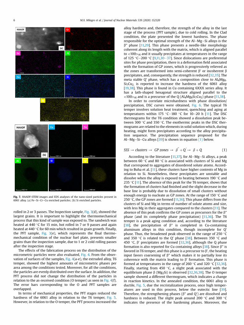
Fig. 7. HAADF-STEM images and EDS analyses of the nano-sized particles present in6061 alloy. (a) FeeSieCreCu enriched particles; (b) Si enriched particles.
M.X. Milagre et al. / Journal of Nuclear Materials 539 (2020) 1523206
rolled in 2 or 3 passes. The Inspection sample, Fig. 3(d), showed thelargest grains. It is important to highlight the thermomechanicalprocess that this kind of sample was exposed to. The sandwich washeated at 440 �C for 15 min, hot rolled in 7 or 9 passes and againheated at 440 �C for 60 minwhich resulted in grain growth. Finally,the PFT sample, Fig. 3(e), which represents the final thermo-mechanical condition of the nuclear fuel plate, presents smallergrains than the inspection sample, due to 1 or 2 cold rolling passesafter the inspection stage.
The effects of the fabrication process on the distribution of themicrometric particles were also evaluated, Fig. 4. From the obser-vation of surfaces of the samples, Fig. 4(a-e), the extruded alloy, T6temper, showed the highest amounts of micrometric phases perarea among the conditions tested. Moreover, for all the conditions,the particles are evenly distributed over the surface. In addition, thePFT process did not change the distribution of the particles inrelation to the as-received condition (O temper) as seen in Fig. 4(f).The error bars corresponding to the O and PFT samples areoverlapped.
In terms of mechanical properties, the PFT stages reduced thehardness of the 6061 alloy in relation to the T6 temper, Fig. 5.However, in relation to the O temper, the PFT process increased the
alloy hardness and, therefore, the strength of the alloy in the laststage of the process (PFT sample), due to cold rolling. In the Cladcondition, the plate presented the lowest hardness. The phaseresponsible for the optimal strength of the AleMgeSi alloys is theb’’ phase [11,29]. This phase presents a needle-like morphologycoherent along its length with the matrix, which is aligned parallelto <100>Al and it usually precipitates at temperatures in the rangeof 125 �Ce200 �C [9,11,30e37]. Since dislocations are preferentialsites for phase precipitation, there is a deformation field associatedwith the formation of GP zones, which is progressively relieved asthe zones are transformed into semi-coherent b0 or incoherent bprecipitates, and, consequently, the strength is reduced [32,35]. Themeta stable Q’ phase, which has a composition close to Al4Mg8-Si7Cu2, is reported to increase the hardness of the 6061 alloy[19,38]. This phase is found in Cu containing 6XXX series alloy. Ithas a lath-shaped hexagonal structure aligned parallel to the<100>Al and is a precursor of the Q (Al4Mg8Si7Cu2) phase [11,38].
In order to correlate microhardness with phase dissolution/precipitation, DSC curves were obtained, Fig. 6. The typical T6temper involves solution heat treatment, quenching and aging attemperatures within 175 �Ce180 �C for 10e20 h [11]. The DSCthermograms for the T6 condition showed a dissolution peak be-tween 300 �C and 350 �C. The exothermic peaks in the DSC ther-mograms are related to the elements in solid solutionwhich, duringheating, might form precipitates according to the alloy precipita-tion sequence. The precipitation sequence proposed for theAleMgeSieCu alloys [39] is shown in equation (1) below.
SSS/ clusters / GP zones/ b’’ þQ ’/ bþ Q (1)
According to the literature [11,37], for AleMgeSi alloys, a peakbetween 60 �C and 80 �C is associated with clusters of Si and Mgthat correspond to aggregates of disordered solute atoms. Accord-ing to Buha et al. [11], these clusters have higher contents of Mg inrelation to Si. Nonetheless, these precipitates are unstable anddissolve when the alloy is exposed to heating between 190 �C and235 �C [11]. The absence of this peak for the T6 temper, shows thatthe formation of clusters had finished and the slight decrease in thebase line is probably due to dissolution of small clusters withoutenough energy to nucleate as GP zones. At the range of 150 �C and250 �C, the GP zones are formed [11,36]. This phase differs from theclusters of Si and Mg in terms of number of solute atoms and size,with less Mg in their aggregates compared to the clusters [11]. Theabsence of this peak confirms the GP zones as precursors for the b’’phase (and its completely phase precipitation) [11,36]. The T6temper is a peak aging condition and, according to the literature[38], the precipitation of b’’ is completed in Cu-containingaluminum alloys in this condition, though incomplete for Q0
phase. Thus, the broadened peak observed in the range of 250 �Cand 350 �C is related to the Q0 phase [38]. Between 350 �C and450 �C, b0 precipitates are formed [32,36], although the Q phaseformation is also reported for Cu containing alloys [38]. Since b’’ isfavored in T6 temper, and this phase is a precursor to b0, the heatinginput favors coarsening of b’’ which makes it to partially lose itscoherence with the matrix leading to b0 formation. This phase isformed at temperatures in the range of 260 �C and 320 �C [32,36].Finally, starting from 450 �C, a slight peak associated with theequilibrium phase b (Mg2Si) is observed [32,36,38]. The O tempersample showed a different thermogram, which indicates a changein reaction kinetics. In the annealed condition, the 6061 alloy isductile, Fig. 5, due the recristalization process, once high temper-atures are used in this process, below the eutectic line [39].Therefore, the strengthening phases (b’’ and Q0) are dissolved andhardness is reduced. The slight peak around 200 �C and 300 �Cindicates the presence of the hardening phases. Moreover, the

Fig. 8. (a) EDS maps of the 6061 alloy showing the chemical composition of the micrometric particles.
Fig. 9. Potential vs. time curves for the 6061 alloy in different stages of the picture frame technique during 24 h of immersion in 0.005 mol L�1 NaCl solution.
M.X. Milagre et al. / Journal of Nuclear Materials 539 (2020) 152320 7
higher peak starting at 350 �C and 450 �C related to T6 temper isprobably due to precipitation of Q and b’/B phases and non-dissolved precipitates coarsened during this treatment. The non-dissolved stable phase b, also coarsened, is responsible for thehighest peak at 450 �Ce550 �C.
The PFT process also promotes changes in precipitation reactionkinetics. The Clad corresponds to the stage inwhich the samples areheated to 440 �C for 15 min followed by 2 or 3 passes of hot rolling.This condition presented an exothermic peak around200 �Ce250 �C indicating that b’’ and Q0 phases precipitation are
not favored in this stage of fuel production. Thus, more elementsare in solid solution for this condition. Moreover, the lowesthardness values support these results indicating the dissolution ofstrengthening phases during this stage. The increment of the peakrelated to Q, b0 and b also indicate coarsening of non-dissolvedprecipitates. This result is supported by the reduction in micro-hardess and decreased mechanical resistance [9,33,40]. Whenthese phases are present in the structure, heating after homoge-nization promotes either their coarsening or transformation (suchas from b0 to b) [33]. The maximum hardness is reached when the

Fig. 10. (a) Anodic polarization curves of the 6061 AleMgeSi alloy in different pictureframe technique (PFT) stages obtained after 30 min of immersion in 0.005 mol L�1 ofNaCl solution.
M.X. Milagre et al. / Journal of Nuclear Materials 539 (2020) 1523208
alloy is homogenized before aging, T6 condition. Thus, the lowerhardness related to the conditions of the PFT stages must be due tothe presence of Q, b’ or stable b phases [33].
For the inspection condition, the peak related to b’’ and Q0
phases and the higher microhardness than the Clad conditionindicate that precipitation of these phases is favored during thisstage. Microhardness of the inspection sample was higher than thatof the Clad condition, even after heating at 440 �C for 60 min andshowing the largest grain size, Fig. 3(d). The hardening during hotrolling, by the increases dislocations density, seemingly favored theprecipitation of hardening phases [35,37,41,42]. The absence ofpeaks related to Q, b’ and b phases explains the increased hardnessin relation to the Clad sample. Lastly, in the final PFT stage, a largeamount of elements seemingly is still in solid solution. Hardness ofthe final PFT sample increased in relation to the samples of otherPFT stages, and this is related to the cold rolling process that favorsincrease in dislocation density and precipitation of the hardeningphases, as presented in Fig. 4.
TEM analysis, Fig. 7, show typical nano-sized particles in the6061 alloy. The particles were enriched in Cr, Fe, Cu and Si. Thepresence of Cr, Fe and Si in the constituent particles is due to theirlow solubility and low diffusion rate in Al matrix. Cr is known as agrain refiner and it is also added to improve the corrosion resis-tance of Al alloys [43,44]. Fe is known as an impurity element[39,45e48]. The addition of Cu can also improve the mechanicalproperties of the alloy by precipitation of strengthening phases, butit usually reduces the corrosion resistance of 6XXX Al-alloys[39,49]. Si is added to AleMgeSi alloys to increase their mechani-cal strength. Depending on the heat treatment used, differentamounts and sizes of MgeSi particles will be present in Si-containing Al-alloys. Particles with micrometric sizes are also pre-sent in 6061 alloy. Fig. 8 shows EDX maps indicating the chemicalcomposition of micrometric particles present in the alloy.
The 6061 micrometric particles are, usually, FeeSi or MgeSienriched. These particles are also known as intermetallics (pri-mary impurities) in the microstructure of the AleSieMg matrix.They are formed in the interdendritic regions during solidification
or in the solid state during solution treatment, homogenization, orrecrystallization. Despite the fact that these impurities have beenreported as deleterious for mechanical properties (as sites for crackinitiation and decohesion failure), depending on their chemicalcomposition, they can show resistance to corrosion and oxidationdue to their adherent surface oxides [40,50].
3.2. Corrosion characterization
Open circuit potential (OCP) measurements were recorded forall the conditions tested as a function of time of immersion in0.005 mol L�1 NaCl solution for 24 h, and the results are presentedin Fig. 9. Similar shapes were obtained for all conditions. Initially, asharp increase in OCP was observed. This initial sharp increase inpotential has been related to the oxide film growth naturallyformed over the aluminum surface in contact with the electrolyte[51e53]. Once pitting potential is reached, oxide film breakdownoccurs. Secondly, OCP oscillations at potentials above �0.57 V areobserved indicating localized attack (pitting). The events leading topotential transients during free corrosion of Al alloys were dis-cussed by Isaac et al. [53]. According to authors, the noise producedduring Al alloys exposure to chloride solutions arises due to activesites where pit growth processes are occurring. Moreover, pitstunneling can be changed by many circumstances which explainthe differences seen in the curves oscillations for each samplecondition. Finally, OCP values decreased with time, which is relatedto constant surface activation.
The differences in OCP values for the various conditions testedafter 24 h of exposure to the electrolyte indicate that the thermo-mechanical treatments involved in the fabrication of nuclear platesby PFT affect the electrochemical behavior of the exposed surfaces.This is also evident from the differences in the microstructuresaccording to the thermomechanical treatments. Eckermann et al.[20] found nobler and more stable OCP values associated withnaturally aged alloy (with a small number of MgSi precipitates) inrelation to heat-treated one. The nobler OCP values associated withthe PFT stage and O temper samples compared to the T6 onemay beattributed to phase dissolution and lower content of precipitatesrelated to those conditions [19,54]. The literature also reports po-tential ennoblement due to precipitate coarsening [54].
Fig. 10 shows the anodic polarization curves for the various 6061samples after 30 min of immersion in 0.005 mol L�1 NaCl solution.In general, the PFT process increased the corrosion resistance of the6061 alloy in relation to the as-received, T6 and O conditions. Thecorrosion pathways in the different 6061 samples after anodicpolarization are shown in Fig. 11. The 6061-T6 alloy, Fig. 11(a),showed susceptibility to intergranular corrosion. For the otherconditions, pitting and filiform-like corrosion were the main typesof attack, Fig. 11(bee). Corrosion propagation seems to change fromintergranular corrosion mechanism to an intragranular corrosiontype. In general, the corrosion mechanism in 6XXX alloys is asso-ciated with (1) Fe-enriched particles which are cathodic to thematrix and the (2) MgeSi particles which have an ambiguousbehavior [20,22,23].
Fig. 12(a) shows the surface of the 6061-T6 alloy after anodicpolarization. Corrosion occurs at areas surrounding Fe-enrichedmicrometric particle, Fig. 12(b), which is cathodic to the matrix.Microgalvanic cells are established between this kind of particleand the surrounding matrix, during the OCP measurement period,leading to localized attack, known as trenching. MgeSi particlesbeing anodic to the matrix, are totally and/or partially consumed.The selective dissolution of Mg, a highly active element, leads to aremaining Si-enriched particle at the exposed surface and, conse-quently, polarity reversal, with the matrix becoming anodic to theSi-enriched particle resulting in cavities at the surface, that is, to

Fig. 11. SEM images of the anodic sites after 30 min of exposure to 0.6 mol L�1 NaCl solution at OCP followed by anodic polarization; (a) T6 temper; (b) O temper; (c) cladding (Clad)stage; (d) inspection (Insp.) stage, and (e) picture frame technique (PFT) final stage.
M.X. Milagre et al. / Journal of Nuclear Materials 539 (2020) 152320 9
trenching.According to Guillaumin et al. [23], intergranular attack in 6XXX
alloys starts at the pit walls and corrosion spreads from the pitthrough grain boundary pathways. According to these authors, pitsnucleated on and/or around MgeSi particles. Also, they proposedthat intergranular corrosion occurred due to preferential dissolu-tion of precipitate free zones (PFZ) along grain boundaries, since forthe 6056 alloy studied in their work, the particles at grain bound-aries are SieCu enriched (being a high Cu-content alloy), whereasthe regions surrounding these precipitates are depleted in theseelements. In this study, the grain boundary particles comprisedMgSi particles, that are anodic to the matrix of the 6061-T6 alloy.MgeSi particles are predominant in the alloy of this study because6061 is a lean alloy with lower Cu-content compared with the 6056alloy. Therefore, the particles at the grain boundaries will dissolvepreferentially, resulting in intergranular corrosion. This attack isfavored when cathodic Fe-enriched particles are close to the grainboundary particles, as shown in Fig. 12. Howerver, due to the PFTprocess, precipitation of the anodic phases is favored inside thegrains.
The corrosion mechanism of the 6061 alloy was also evaluatedby electrochemical impedance spectroscopy (EIS) after 24 h ofimmersion in 0.005mol L�1, Fig.13. All the curves presented similarshapes suggesting similar mechanisms for all the samples withdifferences only in the magnitudes of impedance. The resultsindicated two time constants. In the Nyquist diagrams, all thesamples presented a flattened capacitive arc at high to mediumfrequencies which were related to the interaction between the thinoxide film at the surface and charge transfer processes coupled tocharging of the double layer. At low frequencies, the EIS resultssuggest the presence of diffusion controlled corrosion processes.Despite the contribution of these processes at low frequencies,there is also contribution of other factors, since the slope of |Z| vs.frequency plot related to diffusion controlled processes is around0.5 and the phase angle value is about 45� [55]. For the 6061samples tested, the slope of |Z| vs. frequency plot is in the rangebetween 0 and 0.5. The EIS results also showed impedances in thesame range, tenths of kU.cm2, for all tested conditions. Conse-quently, significant differences between the varios conditionstested were not clearly identified by EIS tests.

Fig. 12. (a) SEM image of the exposed surface of 6061-T6 after polarization showing the corrosion features associated with the micrometric particles; (b) EDX analysis of the FeeSienriched micrometric particle.
Fig. 13. EIS diagrams obtained for 6061 alloy in different picture frame technique (PFT) stages immersed in 0.005 mol L�1 NaCl solution for 24 h.
M.X. Milagre et al. / Journal of Nuclear Materials 539 (2020) 15232010
In order to confirm the differences in the intergranular corrosionsusceptibility of the 6061 alloy for the different stages of the PFTprocess, the samples were exposed to the ASTM G110 standardpractice solution for 6 h. Surface features of the tested samples afterimmersion are shown in Fig. 14. The results are in accordance withFig. 11. The T6 temper exhibited the highest susceptibility tointergranular corrosion among the tested ones, Fig. 14(a). Intra-granular attack was observed for the other conditions due to pre-cipitation of anodic phases inside the grains, Fig. 14(bee). Despitethe intergranular corrosion observed for the O temper (Fig. 11(b)),and Clad stage (Fig. 11(c)), intragranular attack was the mainmechanism of corrosion propagation in the PFT conditions. Cross-section images also confirmed the transition from intergranularto intragranular attack for the PFT 6061 samples, Fig. 15. The fea-tures observed after intergranular corrosion test provided useful
information on the type of corrosion mechanism related to themicrostructure resulting from the different types of thermo-mechanical treatments to which the various types of samples wereexposed.
4. Conclusions
In summary, according to open circuit potential (OCP) mea-surements and polarization curves the thermomechanical pro-cesses involved in the picture frame technique (PFT) results inincreased corrosion resistance of the 6061 alloy in relation to as-received T6 temper condition. Electrochemical impedance spec-troscopy (EIS) results suggested similar electrochemical mecha-nisms of corrosion for all tested conditions. Corrosion propagationin the 6061-T6 alloy was mainly through grain boundaries

Fig. 14. SEM images of 6061 in different picture frame techniques (PFT) stages exposed to a solution composed of 57 g of NaCl and 10 mL of H2O2 in deionized H2O to complete 1 L(ASTM G110) for 6 h. (a) T6 commercial temper; (b) O commercial temper; (c) cladding (Clad) stage; (d) inspection (Insp) stage; (e) picture frame technique (PFT) final stage.
Fig. 15. Cross section SEM images of 6061 in different picture frame techniques (PFT) stages exposed to a solution composed of 57 g of NaCl and 10 mL of H2O2 in deionized H2O tocomplete 1 L (ASTM G110) for 6 h. (a) T6 commercial temper; (b) O commercial temper; (c) cladding (Clad) stage; (d) inspection (Insp) stage; (e) picture frame technique (PFT) finalstage.
M.X. Milagre et al. / Journal of Nuclear Materials 539 (2020) 152320 11

M.X. Milagre et al. / Journal of Nuclear Materials 539 (2020) 15232012
(intergranular). The corroded surfaces and cross-section observa-tions after exposure to test solutions showed that themechanism ofcorrosion propagation varied from intergranular, in the case of T6temper, to intragranular type, for the samples corresponding to PFTstages.
Data availability
The raw/processed data required to reproduce these findingscannot be shared at this time as the data also forms part of anongoing study.
Acknowledgements
The authors acknowledge the National Comission for NuclearEnergy (CNEN) in Brazil for financial support to this work and forthe grant of Mariana X. Milagre (SEI 01342.002357/2019e32). Ac-knowledgements are due to Dr. Duclerc Fernandes Parra and Dr.Margarida Mizue Hamada, from Nuclear and Energy ResearchInstitute (IPEN/CNEN-SP) for technical support with DSC analysisand to LNANO/CNPEM, Brazil, for technical support with TEManalysis.
Appendix A. Supplementary data
Supplementary data to this article can be found online athttps://doi.org/10.1016/j.jnucmat.2020.152320.
References
[1] ASM Handbook Properties and Selection: Nonferrous Alloys and Special-Purpose Materials, ASM International, 2001. http://books.google.com.hk/books?id¼eC-Zt1J4oCgC.
[2] D. F�eron, Overview of nuclear materials and nuclear corrosion science andengineering, Nucl. Corros. Sci. Eng. (2012) 31e56, https://doi.org/10.1533/9780857095343.1.31.
[3] R.H. Howard, R.C. Gallagher, K.G. Field, Mechanical performance of neutron-irradiated dissimilar transition joints of aluminum alloy 6061-T6 and 304Lstainless steel, J. Nucl. Mater. 508 (2018) 348e353, https://doi.org/10.1016/j.jnucmat.2018.05.070.
[4] S.M.D.C. Fernandes, O.V. Correa, J.A.B. De Souza, R.A. Antunes, N.B. De Lima,L.D.V. Ramanathan, Effect of processing on microstructure and corrosionmitigating properties of hydrotalcite coatings on aa 6061 alloy, Mater. Res. 18(2015) 1203e1208, https://doi.org/10.1590/1516-1439.015715.
[5] A.F. Forte Giacobone, S.A. Rodriguez, A.L. Burkart, R.A. Pizarro, Microbiologicalinduced corrosion of AA 6061 nuclear alloy in highly diluted media by Bacilluscereus RE 10, Int. Biodeterior. Biodegrad. 65 (2011) 1161e1168, https://doi.org/10.1016/j.ibiod.2011.08.012.
[6] I.M. Elseaidy, M.M. Ibrahim, M.M. Ghoneim, M.E.A. El-Azim, Aluminum alloysstrengthening by accumulative roll- bonding (arb) process, in: Trans SMiRT(Ed.) 19, 2007, pp. 1e10. Toronto.
[7] C. Vargel, M. Jacques, D. Schmidt, The most common wrought aluminiumalloys, Corros. Alum. (2004) 61e69.
[8] S. Pogatscher, H. Antrekowitsch, H. Leitner, T. Ebner, P.J. Uggowitzer, Mech-anisms controlling the artificial aging of Al-Mg-Si Alloys, Acta Mater. 59(2011) 3352e3363, https://doi.org/10.1016/j.actamat.2011.02.010.
[9] G.A. Edwards, K. Stiller, G.L. Dunlop, M.J. Couper, The precipitation sequence inAl-Mg-Si alloys, Acta Mater. 46 (1998) 3893e3904, https://doi.org/10.1016/S1359-6454(98)00059-7.
[10] S.J. Andersen, Quantification of the Mj2Si/3" and/3’ phases by transmissionelectron microscopy, Metall. Mater. Trans. 26 (1995) 1931e1937.
[11] J. Buha, R.N. Lumley, A.G. Crosky, K. Hono, Secondary precipitation in an Al-Mg-Si-Cu alloy, Acta Mater. 55 (2007) 3015e3024, https://doi.org/10.1016/j.actamat.2007.01.006.
[12] M.A. van Huis, J.H. Chen, H.W. Zandbergen, M.H.F. Sluiter, Phase stability andstructural relations of nanometer-sized, matrix-embedded precipitate phasesin Al-Mg-Si alloys in the late stages of evolution, Acta Mater. 54 (2006)2945e2955, https://doi.org/10.1016/j.actamat.2006.02.034.
[13] V. Massardier, T. Epicier, Study of influence of low copper addition and of anexcess of silicon on the precipitation kinetics and on the precipitationsequence of Al-Mg2Si alloys, Mater. Sci. Forum (2002) 396e402, https://doi.org/10.1007/978-1-4614-7990-1, 851e856.
[14] C. Cayron, P.A. Buffat, Transmission electron microscopy study of the b0 phase(Al-Mg-Si alloys) and QC phase (Al-Cu-Mg-Si alloys): ordering mechanismand crystallographic structure, Acta Mater. 48 (2000) 2639e2653, https://
doi.org/10.1016/S1359-6454(00)00057-4.[15] V. Garric, K. Colas, P. Donnadieu, G. Renou, S. Urvoy, B. Kapusta, Correlation
between quenching rate, mechanical properties and microstructure in thicksections of AleMgeSi(eCu) alloys, Mater. Sci. Eng. 753 (2019) 253e261,https://doi.org/10.1016/j.msea.2019.03.045.
[16] M. Jelani, Z. Li, Z. Shen, M. Sardar, Thermomechanical response of aluminumalloys under the combined action of tensile loading and laser irradiations,Chin. Phys. B 27 (2018), https://doi.org/10.1088/1674-1056/27/3/037901.
[17] C.Y. Cui, T.Y. Wan, Y.X. Shu, S. Meng, X.G. Cui, J.Z. Lu, Y.F. Lu, Microstructureevolution and mechanical properties of aging 6061 Al alloy via laser shockprocessing, J. Alloys Compd. 803 (2019) 1112e1118, https://doi.org/10.1016/j.jallcom.2019.06.347.
[18] Y. Wang, Y. Zhao, X. Xu, D. Pan, W. Jiang, X. Chong, Simultaneously enhancedstrength and ductility of Al-Mg-Si alloys during aging process induced byelectro-pulsing treatment, Materials 12 (2019), https://doi.org/10.3390/ma12091383.
[19] K. El-Menshawy, A.W.A. El-Sayed, M.E. El-Bedawy, H.A. Ahmed, S.M. El-Raghy,Effect of aging time at low aging temperatures on the corrosion of aluminumalloy 6061, Corros. Sci. 54 (2012) 167e173, https://doi.org/10.1016/j.corsci.2011.09.011.
[20] F. Eckermann, T. Suter, P.J. Uggowitzer, A. Afseth, P. Schmutz, The influence ofMgSi particle reactivity and dissolution processes on corrosion in Al-Mg-Sialloys, Electrochim. Acta 54 (2008) 844e855, https://doi.org/10.1016/j.electacta.2008.05.078.
[21] N. Birbilis, R.G. Buchheit, Electrochemical characteristics of intermetallicphases in aluminum alloys, J. Electrochem. Soc. 152 (2005) B140, https://doi.org/10.1149/1.1869984.
[22] C. Blanc, G. Mankowski, Susceptibility to pitting corrosion of 6056 aluminiumalloy, Corros. Sci. 39 (1997) 949e959, https://doi.org/10.1016/S0010-938X(97)81160-2.
[23] V. Guillaumin, G. Mankowski, Localized corrosion of 6056 T6 aluminium alloyin chloride media, Corros. Sci. 42 (2000) 105e125, https://doi.org/10.1016/S0010-938X(98)00116-4.
[24] J.M.C. Mol, J. Van De Langkruis, J.H.W. De Wit, S. Van Der Zwaag, An integratedstudy on the effect of pre- and post-extrusion heat treatments and surfacetreatment on the filiform corrosion properties of an aluminium extrusionalloy, Corros. Sci. 47 (2005) 2711e2730, https://doi.org/10.1016/j.corsci.2004.11.003.
[25] Y. Ma, X. Zhou, W. Huang, G.E. Thompson, X. Zhang, C. Luo, Z. Sun, Localizedcorrosion in AA2099-T83 aluminum-lithium alloy: the role of intermetallicparticles, Mater. Chem. Phys. 161 (2015) 201e210, https://doi.org/10.1016/j.matchemphys.2015.05.037.
[26] E. Linardi, J. Collet-Lacoste, L. Lanzani, Characterization of AA6061 alloy oxidesobtained in high Purity water and in diluted NaCl solution, Procedia Mater.Sci. 8 (2015) 56e64, https://doi.org/10.1016/j.mspro.2015.04.048.
[27] J. Huang, D. Lister, S. Uchida, L. Liu, The corrosion of aluminium alloy andrelease of intermetallic particles in nuclear reactor emergency core coolant:implications for clogging of sump strainers, Nucl. Eng. Technol. 51 (2019)1345e1354, https://doi.org/10.1016/j.net.2019.02.012.
[28] E. Linardi, R. Haddad, L. Lanzani, Stability analysis of the Mg2Si phase in AA6061 aluminum alloy, Procedia Mater. Sci. 1 (2012) 550e557, https://doi.org/10.1016/j.mspro.2012.06.074.
[29] M. Takeda, F. Ohkubo, T. Shirai, K. Fukui, Stability of metastable phases andmicrostructures in the ageing process of Al-Mg-Si ternary alloys, J. Mater. Sci.33 (1998) 2385e2390, https://doi.org/10.1023/A:1004355824857.
[30] C. Badini, F. Marino, DSC study of ageing sequence in 6061aluminum alloy-SiCwhiskers composite, Mater. Chem. Phys. 25 (1990) 57e70.
[31] C.D. Marioara, S.J. Andersen, H.W. Zandbergen, R. Holmestad, The influence ofalloy composition on precipitates of the Al-Mg-Si system, Metall. Mater. Trans.A Phys. Metall. Mater. Sci. 36 (2005) 691e702, https://doi.org/10.1007/s11661-005-1001-7.
[32] I. Dutta, S.M. Allen, A calorimetric study of precipitation in commercialaluminium alloy 6061, J. Mater. Sci. Lett. 10 (1991) 323e326, https://doi.org/10.1007/BF02670289.
[33] S. Zajac, B. Bengtsson, C. J€onsson, Influence of cooling after homogenisationand reheating to extrusion on extrudability and final properties of AA 6063and AA6082 alloys, Mater. Sci. Forum (2002) 396e402. https://doi.org/10.4028/www.scientific.net/msf.396-402.399, 399e404.
[34] L. Sagalowicz, G. Lapasset, G. Hug, Transmission electron microscopy study ofa precipitate which forms in the Al-Mg-Si system, Phil. Mag. Lett. 74 (1996)57e66, https://doi.org/10.1080/095008396180407.
[35] M.H. Jacobs, The structure of the metastable precipitates formed duringageing of an Al-Mg-Si alloy, Philos. Mag. 26 (1972) 1e13, https://doi.org/10.1080/14786437208221015.
[36] J.A. Vargas, J.E. Torres, J.A. Pacheco, R.J. Hernandez, Analysis of heat inputeffect on the mechanical properties of Al-6061-T6 alloy weld joints, Mater.Des. 52 (2013) 556e564, https://doi.org/10.1016/j.matdes.2013.05.081.
[37] I. Dutta, S.M. Allen, J.L. Hafley, Effect of reinforcement on the aging response ofcast 6061 Al-Al2O3 particulate composites, Metall. Trans. A, Phys. Metall.Mater. Sci. 22A (1991) 2553e2563, https://doi.org/10.1007/BF02851349.
[38] R. Braun, Investigations on the long-term stability of 6013-T6 sheet, Mater.Char. 56 (2006) 85e95, https://doi.org/10.1016/j.matchar.2005.03.006.
[39] H.Q. Wang, W.L. Sun, Y.Q. Xing, Microstructure analysis on 6061 aluminumalloy after casting and diffuses annealing process, Phys. Procedia. 50 (2013)68e75, https://doi.org/10.1016/j.phpro.2013.11.013.

M.X. Milagre et al. / Journal of Nuclear Materials 539 (2020) 152320 13
[40] B. Milkereit, N. Wanderka, C. Schick, O. Kessler, Continuous cooling precipi-tation diagrams of Al-Mg-Si alloys, Mater. Sci. Eng. 550 (2012) 87e96, https://doi.org/10.1016/j.msea.2012.04.033.
[41] W.S. Ebhota, T.-C. Jen, Intermetallics formation and their effect on mechanicalproperties of Al-Si-X alloys, Intermet. Compd. - Form. Appl. (2018), https://doi.org/10.5772/intechopen.73188.
[42] C. Badini, F. Marino, A. Tomasi, Natural aging characteristics of aluminiumalloy 6061 reinforced with SiC whiskers and particles, Mater. Sci. Eng. 136(1991) 99e107, https://doi.org/10.1016/0921-5093(91)90445-S.
[43] J. Wloka, S. Virtanen, Microstructural effects on the corrosion behavior ofhigh-strength Al-Zn-Mg-Cu alloys in an overaged condition, J. Electrochem.Soc. 154 (2007) 411e423, https://doi.org/10.1149/1.2742792.
[44] Z. Szklarska-Smialowska, Insight into the pitting corrosion behavior ofaluminum alloys, Coi’rosion Sci. 33 (1992) 1193e1202. http://ac.els-cdn.com.manchester.idm.oclc.org/0010938X9290130U/1-s2.0-0010938X9290130U-main.pdf?_tid¼e81aefc2-657e-11e7-841b-00000aacb35f&acdnat¼1499698319_4df8eb9d0f9d8d25160620a859ff6b10.
[45] G.S. Chen, M. Gao, R.P. Wei, Microconstituent-Induced pitting corrosion inaluminum alloy 2024-T3, Corrosion 52 (1996) 8e15, https://doi.org/10.5006/1.3292099.
[46] A. Davoodi, J. Pan, C. Leygraf, S. Norgren, Probing of local dissolution of Al-alloys in chloride solutions by AFM and SECM, Appl. Surf. Sci. 252 (2006)5499e5503, https://doi.org/10.1016/j.apsusc.2005.12.023.
[47] T.T.M. Tran, B. Tribollet, E.M.M. Sutter, New insights into the cathodic disso-lution of aluminium using electrochemical methods, Electrochim. Acta (2016),https://doi.org/10.1016/j.electacta.2016.09.011.
[48] W. Zhang, S. Ruan, D.A. Wolfe, G.S. Frankel, Statistical model for intergranularcorrosion growth kinetics, Corros. Sci. 45 (2003) 353e370, https://doi.org/10.1016/S0010-938X(02)00090-2.
[49] G. Svenningsen, M.H. Larsen, J.H. Nordlien, K. Nisancioglu, Effect of hightemperature heat treatment on intergranular corrosion of AlMgSi(Cu) modelalloy, Corros. Sci. 48 (2006) 258e272, https://doi.org/10.1016/j.corsci.2004.12.003.
[50] P. Schumacher, S. Pogatscher, M.J. Starink, C. Schick, V. Mohles, B. Milkereit,Quench-induced precipitates in Al-Si alloys: calorimetric determination ofsolute content and characterisation of microstructure, Thermochim. Acta 602(2015) 63e73, https://doi.org/10.1016/j.tca.2014.12.023.
[51] T. Hagyard, W.B. Earl, Potential of aluminum in Aqueous chloride solutions,J. Electrochem. Soc. 114 (1967) 694, https://doi.org/10.1149/1.2426708.
[52] T. Hagyard, W.B. Earl, K.J. Kirkpatrick, I.G. Watson, The electrode potential ofevaporated aluminum films in chloride solution, J. Electrochem. Soc. 113(1966) 962, https://doi.org/10.1149/1.2424170.
[53] H.S. Isaacs, C. Scheffey, R. Huang, The location of events producing potentialtransients during pitting of freely corroding Al and its alloys, ECS Trans 11(2008) 1e12, https://doi.org/10.1149/1.2925257.
[54] R. Ly, A.I. Karayan, K.T. Hartwig, H. Castaneda, Insights into the electro-chemical response of a partially recrystallized Al-Mg-Si alloy and its rela-tionship to corrosion events, Electrochim. Acta 308 (2019) 35e44, https://doi.org/10.1016/j.electacta.2019.03.220.
[55] R.G. Kelly, J.R. Scully, D.W. Shoesmith, R.G. Buchheit, Electrochemical Tech-niques in Corrosion Science and Engineering, Marcel Dekker, New York, 2003,https://doi.org/10.1016/s0013-4686(02)00768-5.


![Journal of Nuclear Materials - INL Advanced Reactor ... Situ...the properties of nuclear graphite [5–10]. Under irradiation, polycrystalline graphite undergoes complex dimensional](https://static.fdocuments.net/doc/165x107/60f85869ae21df3ef94aa65a/journal-of-nuclear-materials-inl-advanced-reactor-situ-the-properties-of.jpg)