
Journal of Microwaves, Optoelectronics and Electromagnetic ... · Journal of Microwaves,...
13
Journal of Microwaves, Optoelectronics and Electromagnetic Applications, Vol. 14, n.1, June 2015 http://dx.doi.org/10.1590/2179-10742015v14i1422 Brazilian Microwave and Optoelectronics Society-SBMO received 6 Mar 2014; for review 6 Mar 2014; accepted 16 Jan 2015 Brazilian Society of Electromagnetism-SBMag © 2015 SBMO/SBMag ISSN 2179-1074 1 A Compact Dual-Band Octagonal Slotted Printed Monopole Antenna for WLAN/ WiMAX and UWB Applications Praveen V. Naidu 1 and Raj Kumar 2 1 Centre for Radio Science Studies, Symbiosis International University (DU), Pune, India 2 ARDE, Pashan, Pune - 411 025, India Email: [email protected] Abstract - A compact (20 x 20 mm 2 size), coplanar waveguide (CPW) fed, octagonal slotted, dual-band antenna is presented in this paper. The proposed antenna has a simple structure consisting of an octagonal slot, L-shape stub, and a two stepped rectangular patch. The introduction of the L-shaped metallic stubs in the ground plane generates a lower resonance frequency at 2.42 GHz. The proposed antenna is fabricated on a low cost FR4 substrate having thickness of 1.6 mm. The measured impedance bandwidth of the proposed antenna is from 2.40 to 2.46 GHz and 3.2 to 6.2 GHz. It is also shown that the proposed antenna has stable radiation patterns of almost dumb-bell shape in the E-plane and omni-directional shape in the H-plane. The effects of various design parameters on the impedance bandwidth are also studied and presented in detail. The proposed antenna can be used for 3.5/5.5 GHz worldwide interoperability for microwave access (WiMAX), 2.4/5.2/5.8 GHz wireless local area network (WLAN) and 3.1-6.0 GHz Direct-Sequence Code Division Multiple Access (DS-CDMA) / Multi-Band Orthogonal Frequency Division Multiplexing (MB- OFDM) ultra wideband (UWB) applications. Index Terms – CPW-fed, DS-CDMA, MB-OFDM, dual-band, slot antenna, WLAN, WiMAX and UWB antenna. I. INTRODUCTION In recent years, much attention has been paid towards the development of multi-band antennas with low cost, compact size and ease of fabrication. These antennas are required to have higher performance and intended for wireless communication applications such as wireless local area network (WLAN), worldwide interoperability for microwave access (WiMAX) and MB-OFDM / DS- CDMA UWB systems. Many printed dual-band and UWB monopole antennas were reported for various wireless applications in the literature [1-13]. Among them, CPW-fed slot antennas have many advantages like simple structure, ease of fabrication, wide impedance bandwidth, less radiation loss and ease of integration with monolithic microwave integrated circuits (MMIC). A 60 x 45 mm 2 and 40 x 40 mm 2 size dual-band slot antennas for 2.4/5 GHz WLAN applications are proposed in [1-2] respectively. In [3], a 32 x 16 mm 2 size ring monopole antenna with two meander lines was reported for 2.4/5 GHz dual-band operations. Similarly several dual-band slot
-
Upload
duongkhuong -
Category
Documents
-
view
234 -
download
0
Transcript of Journal of Microwaves, Optoelectronics and Electromagnetic ... · Journal of Microwaves,...
Journal of Microwaves, Optoelectronics and Electromagnetic Applications, Vol. 14, n.1, June 2015 http://dx.doi.org/10.1590/2179-10742015v14i1422
Brazilian Microwave and Optoelectronics Society-SBMO received 6 Mar 2014; for review 6 Mar 2014; accepted 16 Jan 2015 Brazilian Society of Electromagnetism-SBMag © 2015 SBMO/SBMag ISSN 2179-1074
1
A Compact Dual-Band Octagonal Slotted Printed Monopole Antenna for WLAN/
WiMAX and UWB Applications Praveen V. Naidu1 and Raj Kumar2
1Centre for Radio Science Studies, Symbiosis International University (DU), Pune, India 2ARDE, Pashan, Pune - 411 025, India
Email: [email protected]
Abstract - A compact (20 x 20 mm2 size), coplanar waveguide (CPW) fed, octagonal slotted, dual-band antenna is presented in this paper. The proposed antenna has a simple structure consisting of an octagonal slot, L-shape stub, and a two stepped rectangular patch. The introduction of the L-shaped metallic stubs in the ground plane generates a lower resonance frequency at 2.42 GHz. The proposed antenna is fabricated on a low cost FR4 substrate having thickness of 1.6 mm. The measured impedance bandwidth of the proposed antenna is from 2.40 to 2.46 GHz and 3.2 to 6.2 GHz. It is also shown that the proposed antenna has stable radiation patterns of almost dumb-bell shape in the E-plane and omni-directional shape in the H-plane. The effects of various design parameters on the impedance bandwidth are also studied and presented in detail. The proposed antenna can be used for 3.5/5.5 GHz worldwide interoperability for microwave access (WiMAX), 2.4/5.2/5.8 GHz wireless local area network (WLAN) and 3.1-6.0 GHz Direct-Sequence Code Division Multiple Access (DS-CDMA) / Multi-Band Orthogonal Frequency Division Multiplexing (MB-OFDM) ultra wideband (UWB) applications.
Index Terms – CPW-fed, DS-CDMA, MB-OFDM, dual-band, slot antenna, WLAN, WiMAX and UWB antenna.
I. INTRODUCTION
In recent years, much attention has been paid towards the development of multi-band antennas with
low cost, compact size and ease of fabrication. These antennas are required to have higher
performance and intended for wireless communication applications such as wireless local area
network (WLAN), worldwide interoperability for microwave access (WiMAX) and MB-OFDM / DS-
CDMA UWB systems. Many printed dual-band and UWB monopole antennas were reported for
various wireless applications in the literature [1-13]. Among them, CPW-fed slot antennas have many
advantages like simple structure, ease of fabrication, wide impedance bandwidth, less radiation loss
and ease of integration with monolithic microwave integrated circuits (MMIC).
A 60 x 45 mm2 and 40 x 40 mm2 size dual-band slot antennas for 2.4/5 GHz WLAN applications
are proposed in [1-2] respectively. In [3], a 32 x 16 mm2 size ring monopole antenna with two
meander lines was reported for 2.4/5 GHz dual-band operations. Similarly several dual-band slot
Journal of Microwaves, Optoelectronics and Electromagnetic Applications, Vol. 14, n.1, June 2015 http://dx.doi.org/10.1590/2179-10742015v14i1422
Brazilian Microwave and Optoelectronics Society-SBMO received 6 Mar 2014; for review 6 Mar 2014; accepted 16 Jan 2015 Brazilian Society of Electromagnetism-SBMag © 2015 SBMO/SBMag ISSN 2179-1074
2
antennas like a rectangular shaped slot antenna [4], a cross shaped slot antenna [5] and a triangular
slot antenna [6] were proposed for wholly cover 2.4/5 GHz WLAN bands. Though the reported
antennas cover all 2.4/5 GHz WLAN bands, but they are not very compact in size as well as they are
not able to cover 3.5 GHz WiMAX band. In [7], a dual-band monopole antenna is designed by
protruding stubs in the ground plane. The presented antenna has an overall size of 35 x 50 mm2 and it
is covering only 2.4 GHz and 5.8 GHz WLAN bands. In [8], a dual-band slot antenna comprising of
two narrow linear slots for WLAN applications was presented, and in [9], a 50 x 75 mm2 double T-
shaped monopole dual-band antenna was proposed for WLAN applications but both the presented
antennas have a drawback of covering only 2.4 GHz and 5.2 GHz WLAN bands. The dual frequency
operation was achieved by using CPW-fed antenna with inverted L strip and open ended rectangular
ring strip in [10], the overall dimensions of the proposed antenna was 26.5 x 25 mm2 which covers
only 2.4 GHz and 5 GHz WLAN bands.
In [11], a 35 x 24 mm2 size triangular shaped coplanar waveguide fed monopole antenna was
proposed for 2.4/5 GHz WLAN and 3.4 GHz WiMAX applications. But again the overall dimensions
of the antenna are larger when compared with our proposed design (20 x 20 mm2). Also many
researchers have reported UWB antennas [12-13] for MB-OFDM) / lower band DS-CDMA systems
with a frequency range of 3.1 GHz to 4.8 GHz / 3.1 GHz to 5.15 GHz. In [13], a compact 20 × 30
mm2 tree shaped fractal UWB antenna is presented for MB-OFDM lower three band (3.1-4.8 GHz)
applications. Some of the reported antennas perform well in the bandwidth and radiation
characteristics, but because of large relative size, they may be difficult to be integrated with
miniaturized communication devices. So there is a demand for designing compact multi-band
antennas having wideband characteristics. Table 1 shows the comparison of antenna size,
operating bands and antenna purpose of the proposed antenna with antennas reported in
[1-11].
In this paper, we have proposed a compact dual-band CPW-fed octagonal slot with rectangular
shaped patch antenna covering the operating bands of 2.4/5.2/5.8 GHz WLAN bands, 3.5/5.5 GHz
WiMAX band and 3.1-6.0 GHz DS-CDMA/MB-OFDM UWB band. The proposed antenna is
compact in size (20 x 20 mm2), and designed, optimized and simulated using 3D-electromagnetic
software CST Microwave Studio based on the Finite Integration Technique (FIT). The reflection
coefficient characteristic of the fabricated antenna is measured using Rohde & Schwarz Vector
Network Analyzer (R&S ZVA-40) while the radiation patterns and gain are measured in an in-house
anechoic chamber. Finally, the simulated and measured results are compared and discussed.
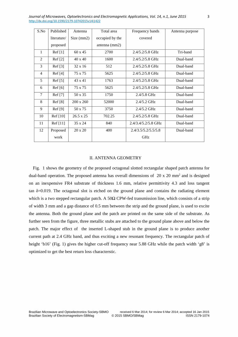
Table 1- Comparison of proposed antenna performance with other compact antennas
Journal of Microwaves, Optoelectronics and Electromagnetic Applications, Vol. 14, n.1, June 2015 http://dx.doi.org/10.1590/2179-10742015v14i1422
Brazilian Microwave and Optoelectronics Society-SBMO received 6 Mar 2014; for review 6 Mar 2014; accepted 16 Jan 2015 Brazilian Society of Electromagnetism-SBMag © 2015 SBMO/SBMag ISSN 2179-1074
3
S.No Published
literature/
proposed
Antenna
Size (mm2)
Total area
occupied by the
antenna (mm2)
Frequency bands
covered
Antenna purpose
1 Ref [1] 60 x 45 2700 2.4/5.2/5.8 GHz Tri-band
2 Ref [2] 40 x 40 1600 2.4/5.2/5.8 GHz Dual-band
3 Ref [3] 32 x 16 512 2.4/5.2/5.8 GHz Dual-band
4 Ref [4] 75 x 75 5625 2.4/5.2/5.8 GHz Dual-band
5 Ref [5] 43 x 41 1763 2.4/5.2/5.8 GHz Dual-band
6 Ref [6] 75 x 75 5625 2.4/5.2/5.8 GHz Dual-band
7 Ref [7] 50 x 35 1750 2.4/5.8 GHz Dual-band
8 Ref [8] 200 x 260 52000 2.4/5.2 GHz Dual-band
9 Ref [9] 50 x 75 3750 2.4/5.2 GHz Dual-band
10 Ref [10] 26.5 x 25 702.25 2.4/5.2/5.8 GHz Dual-band
11 Ref [11] 35 x 24 840 2.4/3.4/5.2/5.8 GHz Dual-band
12 Proposed
work
20 x 20 400 2.4/3.5/5.2/5.5/5.8
GHz
Dual-band
II. ANTENNA GEOMETRY
Fig. 1 shows the geometry of the proposed octagonal slotted rectangular shaped patch antenna for
dual-band operation. The proposed antenna has overall dimensions of 20 x 20 mm2 and is designed
on an inexpensive FR4 substrate of thickness 1.6 mm, relative permittivity 4.3 and loss tangent
tan δ=0.019. The octagonal slot is etched on the ground plane and contains the radiating element
which is a two stepped rectangular patch. A 50Ω CPW-fed transmission line, which consists of a strip
of width 3 mm and a gap distance of 0.5 mm between the strip and the ground plane, is used to excite
the antenna. Both the ground plane and the patch are printed on the same side of the substrate. As
further seen from the figure, three metallic stubs are attached to the ground plane above and below the
patch. The major effect of the inserted L-shaped stub in the ground plane is to produce another
current path at 2.4 GHz band, and thus exciting a new resonant frequency. The rectangular patch of
height ‘b16’ (Fig. 1) gives the higher cut-off frequency near 5.88 GHz while the patch width ‘g8’ is
optimized to get the best return loss characterstic.
Journal of Microwaves, Optoelectronics and Electromagnetic Applications, Vol. 14, n.1, June 2015 http://dx.doi.org/10.1590/2179-10742015v14i1422
Brazilian Microwave and Optoelectronics Society-SBMO received 6 Mar 2014; for review 6 Mar 2014; accepted 16 Jan 2015 Brazilian Society of Electromagnetism-SBMag © 2015 SBMO/SBMag ISSN 2179-1074
4
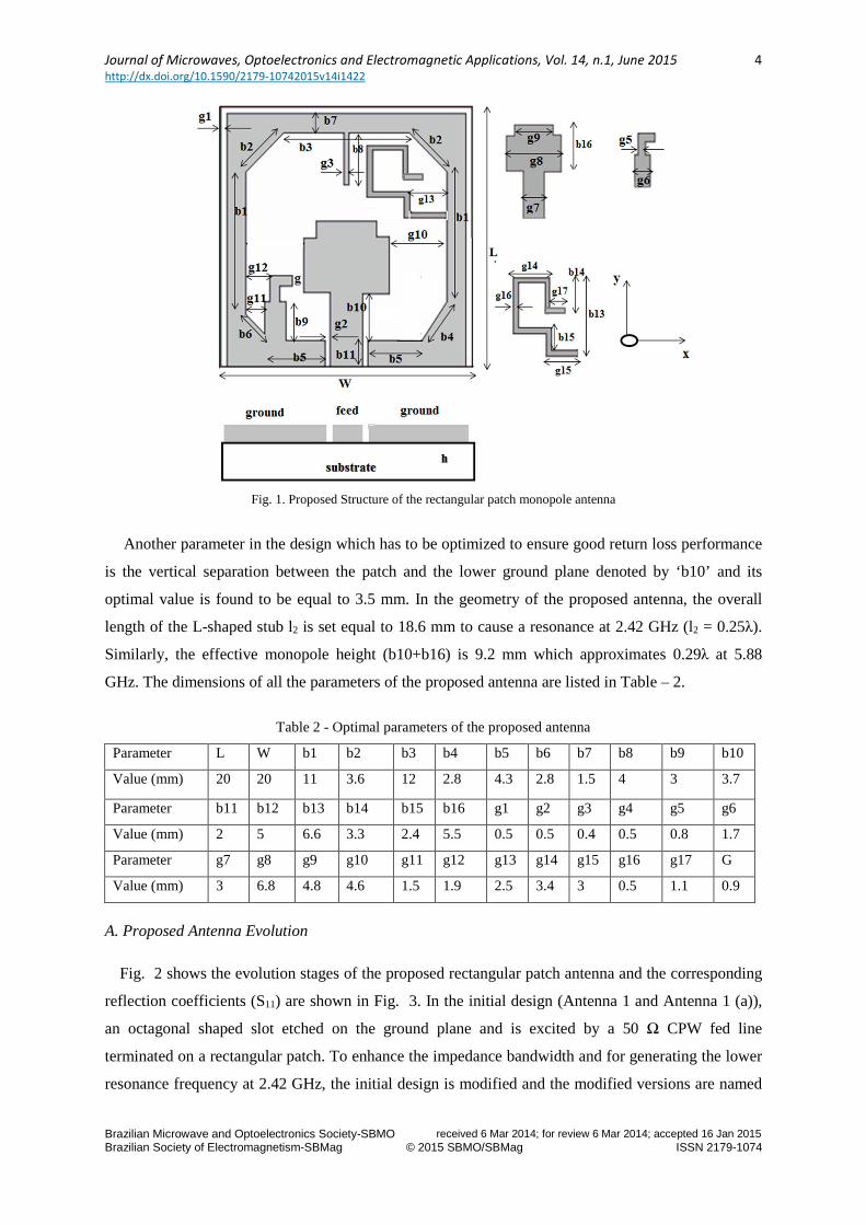
Fig. 1. Proposed Structure of the rectangular patch monopole antenna
Another parameter in the design which has to be optimized to ensure good return loss performance
is the vertical separation between the patch and the lower ground plane denoted by ‘b10’ and its
optimal value is found to be equal to 3.5 mm. In the geometry of the proposed antenna, the overall
length of the L-shaped stub l2 is set equal to 18.6 mm to cause a resonance at 2.42 GHz (l2 = 0.25λ).
Similarly, the effective monopole height (b10+b16) is 9.2 mm which approximates 0.29λ at 5.88
GHz. The dimensions of all the parameters of the proposed antenna are listed in Table – 2.
Table 2 - Optimal parameters of the proposed antenna
Parameter L W b1 b2 b3 b4 b5 b6 b7 b8 b9 b10
Value (mm) 20 20 11 3.6 12 2.8 4.3 2.8 1.5 4 3 3.7
Parameter b11 b12 b13 b14 b15 b16 g1 g2 g3 g4 g5 g6
Value (mm) 2 5 6.6 3.3 2.4 5.5 0.5 0.5 0.4 0.5 0.8 1.7
Parameter g7 g8 g9 g10 g11 g12 g13 g14 g15 g16 g17 G
Value (mm) 3 6.8 4.8 4.6 1.5 1.9 2.5 3.4 3 0.5 1.1 0.9
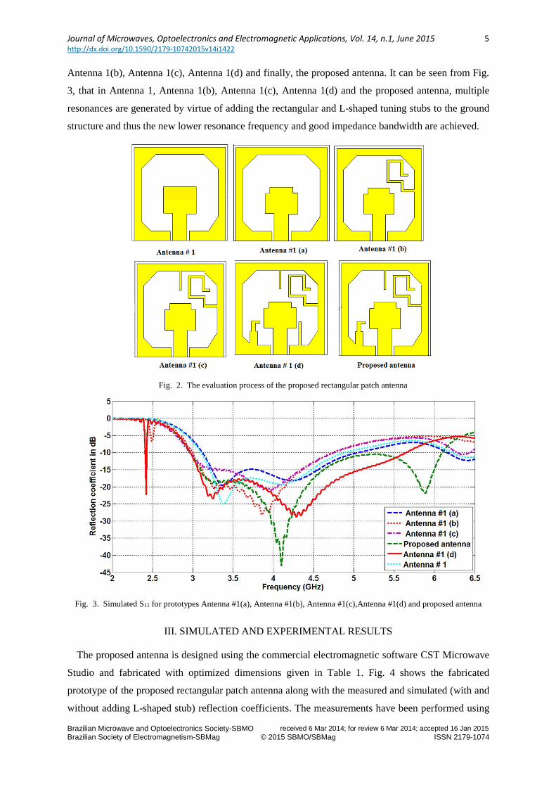
A. Proposed Antenna Evolution
Fig. 2 shows the evolution stages of the proposed rectangular patch antenna and the corresponding
reflection coefficients (S11) are shown in Fig. 3. In the initial design (Antenna 1 and Antenna 1 (a)),
an octagonal shaped slot etched on the ground plane and is excited by a 50 Ω CPW fed line
terminated on a rectangular patch. To enhance the impedance bandwidth and for generating the lower
resonance frequency at 2.42 GHz, the initial design is modified and the modified versions are named
Journal of Microwaves, Optoelectronics and Electromagnetic Applications, Vol. 14, n.1, June 2015 http://dx.doi.org/10.1590/2179-10742015v14i1422
Brazilian Microwave and Optoelectronics Society-SBMO received 6 Mar 2014; for review 6 Mar 2014; accepted 16 Jan 2015 Brazilian Society of Electromagnetism-SBMag © 2015 SBMO/SBMag ISSN 2179-1074
5
Antenna 1(b), Antenna 1(c), Antenna 1(d) and finally, the proposed antenna. It can be seen from Fig.
3, that in Antenna 1, Antenna 1(b), Antenna 1(c), Antenna 1(d) and the proposed antenna, multiple
resonances are generated by virtue of adding the rectangular and L-shaped tuning stubs to the ground
structure and thus the new lower resonance frequency and good impedance bandwidth are achieved.
Fig. 2. The evaluation process of the proposed rectangular patch antenna
Fig. 3. Simulated S11 for prototypes Antenna #1(a), Antenna #1(b), Antenna #1(c),Antenna #1(d) and proposed antenna
III. SIMULATED AND EXPERIMENTAL RESULTS
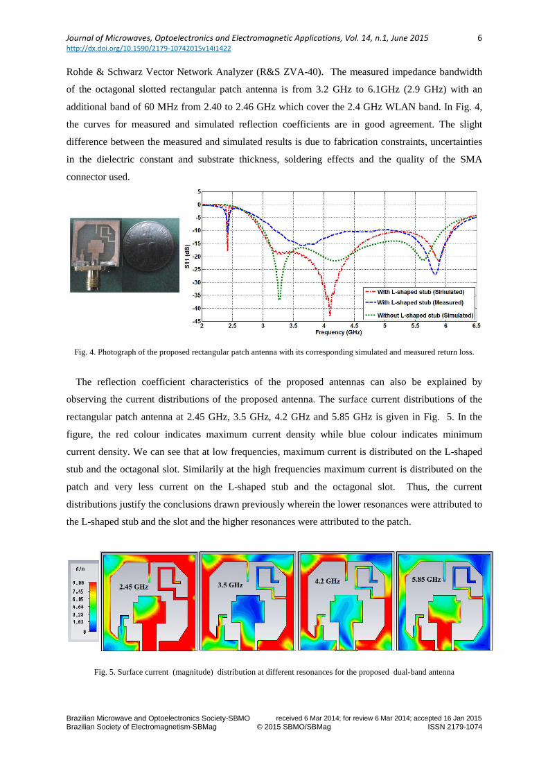
The proposed antenna is designed using the commercial electromagnetic software CST Microwave
Studio and fabricated with optimized dimensions given in Table 1. Fig. 4 shows the fabricated
prototype of the proposed rectangular patch antenna along with the measured and simulated (with and
without adding L-shaped stub) reflection coefficients. The measurements have been performed using
Journal of Microwaves, Optoelectronics and Electromagnetic Applications, Vol. 14, n.1, June 2015 http://dx.doi.org/10.1590/2179-10742015v14i1422
Brazilian Microwave and Optoelectronics Society-SBMO received 6 Mar 2014; for review 6 Mar 2014; accepted 16 Jan 2015 Brazilian Society of Electromagnetism-SBMag © 2015 SBMO/SBMag ISSN 2179-1074
6
Rohde & Schwarz Vector Network Analyzer (R&S ZVA-40). The measured impedance bandwidth
of the octagonal slotted rectangular patch antenna is from 3.2 GHz to 6.1GHz (2.9 GHz) with an
additional band of 60 MHz from 2.40 to 2.46 GHz which cover the 2.4 GHz WLAN band. In Fig. 4,
the curves for measured and simulated reflection coefficients are in good agreement. The slight
difference between the measured and simulated results is due to fabrication constraints, uncertainties
in the dielectric constant and substrate thickness, soldering effects and the quality of the SMA
connector used.
Fig. 4. Photograph of the proposed rectangular patch antenna with its corresponding simulated and measured return loss.
The reflection coefficient characteristics of the proposed antennas can also be explained by
observing the current distributions of the proposed antenna. The surface current distributions of the
rectangular patch antenna at 2.45 GHz, 3.5 GHz, 4.2 GHz and 5.85 GHz is given in Fig. 5. In the
figure, the red colour indicates maximum current density while blue colour indicates minimum
current density. We can see that at low frequencies, maximum current is distributed on the L-shaped
stub and the octagonal slot. Similarily at the high frequencies maximum current is distributed on the
patch and very less current on the L-shaped stub and the octagonal slot. Thus, the current
distributions justify the conclusions drawn previously wherein the lower resonances were attributed to
the L-shaped stub and the slot and the higher resonances were attributed to the patch.
Fig. 5. Surface current (magnitude) distribution at different resonances for the proposed dual-band antenna

Journal of Microwaves, Optoelectronics and Electromagnetic Applications, Vol. 14, n.1, June 2015 http://dx.doi.org/10.1590/2179-10742015v14i1422
Brazilian Microwave and Optoelectronics Society-SBMO received 6 Mar 2014; for review 6 Mar 2014; accepted 16 Jan 2015 Brazilian Society of Electromagnetism-SBMag © 2015 SBMO/SBMag ISSN 2179-1074
7
IV. THEORETICAL ANALYSIS
The contributing factor for the first resonance (fR1) in the final version of the rectangular patch
antenna near 2.42 GHz is the L-shaped tuning stub of length l2=18.6 mm (Fig. 6) and the resonance
frequency is approximately obtained from equation (1). The second resonance near 5.88 GHz is due to
the patch height and dependent on the coupling between the lower edge of the patch and the upper
edge of the ground plane. The second resonance frequency for the proposed antenna can be obtained
from the equation (2).
Fig. 6. L-shaped tuning stub of the proposed rectangular patch antenna
= ,
(1)
= .
, (2)
Where = + (3)
, =
(4)
Here, c stands for the speed of light in free space, l4 is the effective monopole height as given in
equation (3), while εr,eff is the effective relative permittivity to be calculated from equation (4). For
calculating the effective relative permittivity, it is assumed that for a CPW fed monopole, half of the
established field lies in air while the remaining half is distributed in the substrate. The resonance
frequencies are calculated using equations (1) to (4).
V. PARAMETRIC STUDY
A. Effect of the Separation between Patch and Ground
The separation between the patch and the ground plays a crucial role in obtaining wider impedance
bandwidth. Fig. 7 shows the variation in return loss by varying the separation between the patch and
the ground. It can be seen from the figure that a smaller separation gives better impedance matching at
higher frequencies. Hence, the separation b10 needs to be optimized and the optimum value is found
to be 3.7 mm. At this optimum value, the maximum coupling of electromagnetic energy between the
patch and the ground is achieved over a wider bandwidth.
Journal of Microwaves, Optoelectronics and Electromagnetic Applications, Vol. 14, n.1, June 2015 http://dx.doi.org/10.1590/2179-10742015v14i1422
Brazilian Microwave and Optoelectronics Society-SBMO received 6 Mar 2014; for review 6 Mar 2014; accepted 16 Jan 2015 Brazilian Society of Electromagnetism-SBMag © 2015 SBMO/SBMag ISSN 2179-1074
8
Fig.7. Effect of varying the separation gap on return loss
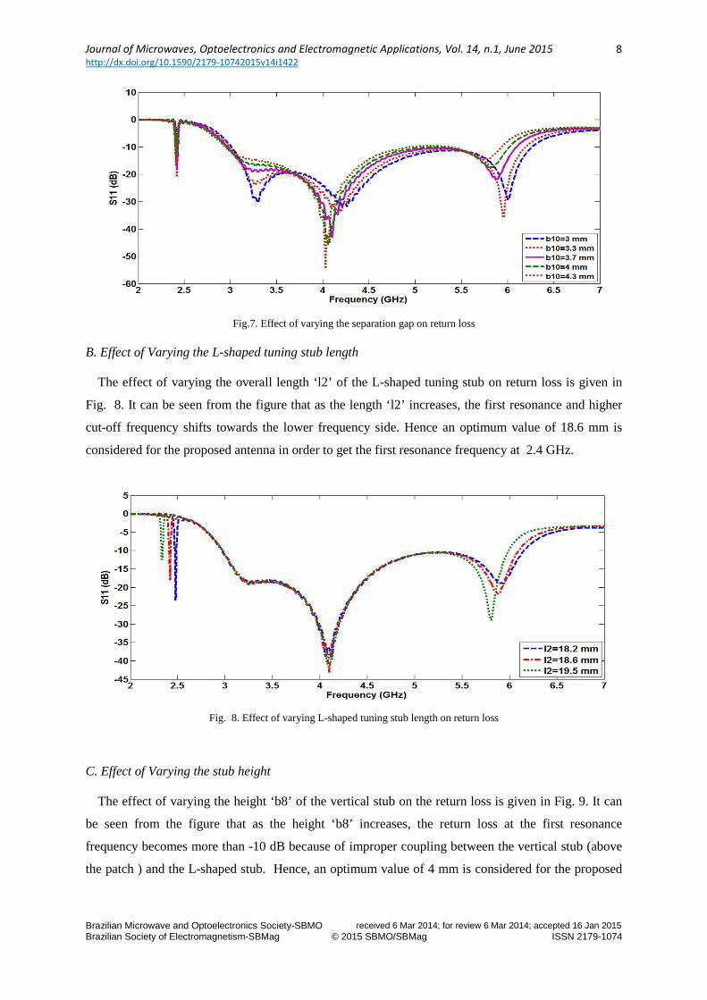
B. Effect of Varying the L-shaped tuning stub length
The effect of varying the overall length ‘l2’ of the L-shaped tuning stub on return loss is given in
Fig. 8. It can be seen from the figure that as the length ‘l2’ increases, the first resonance and higher
cut-off frequency shifts towards the lower frequency side. Hence an optimum value of 18.6 mm is
considered for the proposed antenna in order to get the first resonance frequency at 2.4 GHz.
Fig. 8. Effect of varying L-shaped tuning stub length on return loss
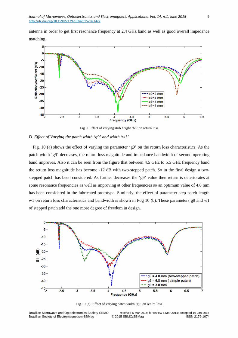
C. Effect of Varying the stub height
The effect of varying the height ‘b8’ of the vertical stub on the return loss is given in Fig. 9. It can
be seen from the figure that as the height ‘b8’ increases, the return loss at the first resonance
frequency becomes more than -10 dB because of improper coupling between the vertical stub (above
the patch ) and the L-shaped stub. Hence, an optimum value of 4 mm is considered for the proposed
Journal of Microwaves, Optoelectronics and Electromagnetic Applications, Vol. 14, n.1, June 2015 http://dx.doi.org/10.1590/2179-10742015v14i1422
Brazilian Microwave and Optoelectronics Society-SBMO received 6 Mar 2014; for review 6 Mar 2014; accepted 16 Jan 2015 Brazilian Society of Electromagnetism-SBMag © 2015 SBMO/SBMag ISSN 2179-1074
9
antenna in order to get first resonance frequency at 2.4 GHz band as well as good overall impedance
matching.
Fig.9. Effect of varying stub height ‘b8’ on return loss
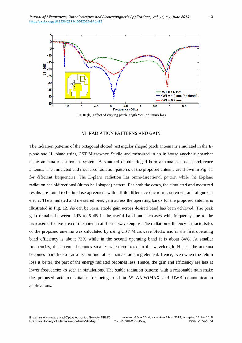
D. Effect of Varying the patch width ‘g9’ and width ‘w1’
Fig. 10 (a) shows the effect of varying the parameter ‘g9’ on the return loss characteristics. As the
patch width ‘g9’ decreases, the return loss magnitude and impedance bandwidth of second operating
band improves. Also it can be seen from the figure that between 4.5 GHz to 5.5 GHz frequency band
the return loss magnitude has become -12 dB with two-stepped patch. So in the final design a two-
stepped patch has been considered. As further decreases the ‘g9’ value then return is deteriorates at
some resonance frequencies as well as improving at other frequencies so an optimum value of 4.8 mm
has been considered in the fabricated prototype. Similarly, the effect of parameter step patch length
w1 on return loss characteristics and bandwidth is shown in Fog 10 (b). These parameters g9 and w1
of stepped patch add the one more degree of freedom in design.
Fig.10 (a). Effect of varying patch width ‘g9’ on return loss
Journal of Microwaves, Optoelectronics and Electromagnetic Applications, Vol. 14, n.1, June 2015 http://dx.doi.org/10.1590/2179-10742015v14i1422
Brazilian Microwave and Optoelectronics Society-SBMO received 6 Mar 2014; for review 6 Mar 2014; accepted 16 Jan 2015 Brazilian Society of Electromagnetism-SBMag © 2015 SBMO/SBMag ISSN 2179-1074
10
Fig.10 (b). Effect of varying patch length ‘w1’ on return loss
VI. RADIATION PATTERNS AND GAIN
The radiation patterns of the octagonal slotted rectangular shaped patch antenna is simulated in the E-
plane and H- plane using CST Microwave Studio and measured in an in-house anechoic chamber
using antenna measurement system. A standard double ridged horn antenna is used as reference
antenna. The simulated and measured radiation patterns of the proposed antenna are shown in Fig. 11
for different frequencies. The H-plane radiation has omni-directional pattern while the E-plane
radiation has bidirectional (dumb bell shaped) pattern. For both the cases, the simulated and measured
results are found to be in close agreement with a little difference due to measurement and alignment
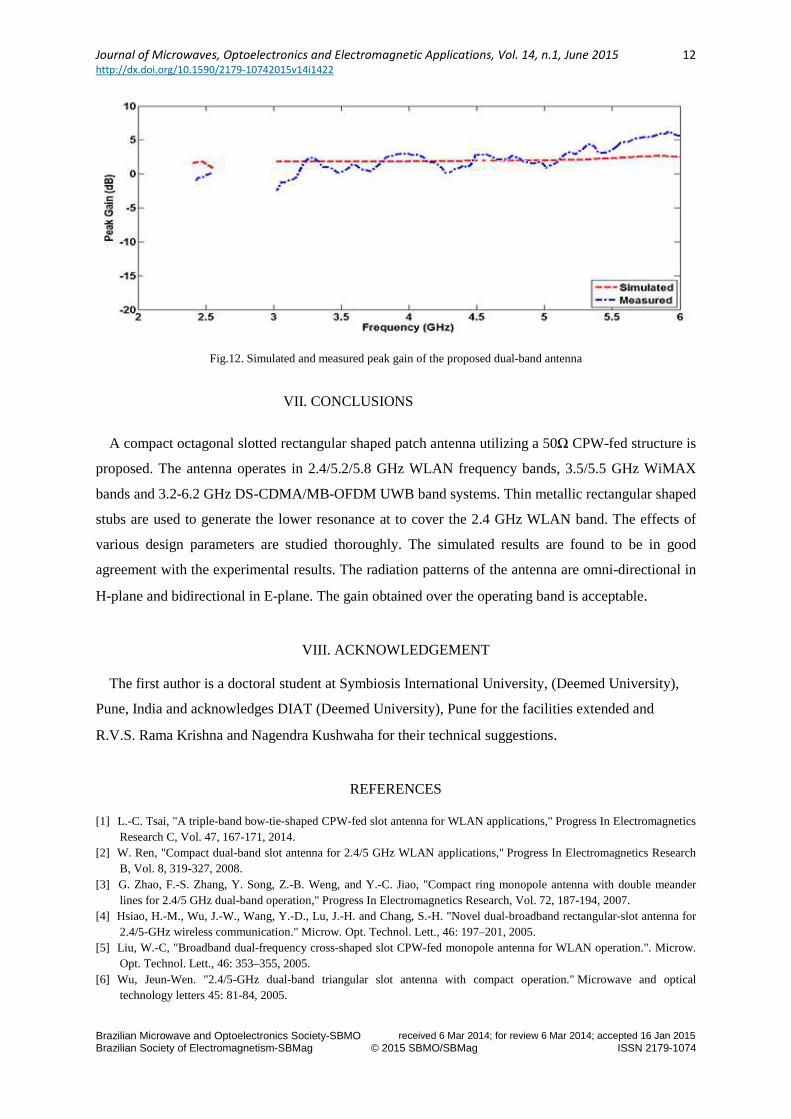
errors. The simulated and measured peak gain across the operating bands for the proposed antenna is
illustrated in Fig. 12. As can be seen, stable gain across desired band has been achieved. The peak
gain remains between -1dB to 5 dB in the useful band and increases with frequency due to the
increased effective area of the antenna at shorter wavelengths. The radiation efficiency characteristics
of the proposed antenna was calculated by using CST Microwave Studio and in the first operating
band efficiency is about 73% while in the second operating band it is about 84%. At smaller
frequencies, the antenna becomes smaller when compared to the wavelength. Hence, the antenna
becomes more like a transmission line rather than as radiating element. Hence, even when the return
loss is better, the part of the energy radiated becomes less. Hence, the gain and efficiency are less at
lower frequencies as seen in simulations. The stable radiation patterns with a reasonable gain make
the proposed antenna suitable for being used in WLAN/WiMAX and UWB communication
applications.

Journal of Microwaves, Optoelectronics and Electromagnetic Applications, Vol. 14, n.1, June 2015 http://dx.doi.org/10.1590/2179-10742015v14i1422
Brazilian Microwave and Optoelectronics Society-SBMO received 6 Mar 2014; for review 6 Mar 2014; accepted 16 Jan 2015 Brazilian Society of Electromagnetism-SBMag © 2015 SBMO/SBMag ISSN 2179-1074
11
Fig. 11. Measured and simulated radiation patterns of rectangular shaped patch antenna at 2.45 GHz, 3.6 GHz and 5.8 GHz frequencies
Journal of Microwaves, Optoelectronics and Electromagnetic Applications, Vol. 14, n.1, June 2015 http://dx.doi.org/10.1590/2179-10742015v14i1422
Brazilian Microwave and Optoelectronics Society-SBMO received 6 Mar 2014; for review 6 Mar 2014; accepted 16 Jan 2015 Brazilian Society of Electromagnetism-SBMag © 2015 SBMO/SBMag ISSN 2179-1074
12
Fig.12. Simulated and measured peak gain of the proposed dual-band antenna
VII. CONCLUSIONS
A compact octagonal slotted rectangular shaped patch antenna utilizing a 50Ω CPW-fed structure is
proposed. The antenna operates in 2.4/5.2/5.8 GHz WLAN frequency bands, 3.5/5.5 GHz WiMAX
bands and 3.2-6.2 GHz DS-CDMA/MB-OFDM UWB band systems. Thin metallic rectangular shaped
stubs are used to generate the lower resonance at to cover the 2.4 GHz WLAN band. The effects of
various design parameters are studied thoroughly. The simulated results are found to be in good
agreement with the experimental results. The radiation patterns of the antenna are omni-directional in
H-plane and bidirectional in E-plane. The gain obtained over the operating band is acceptable.
VIII. ACKNOWLEDGEMENT
The first author is a doctoral student at Symbiosis International University, (Deemed University),
Pune, India and acknowledges DIAT (Deemed University), Pune for the facilities extended and
R.V.S. Rama Krishna and Nagendra Kushwaha for their technical suggestions.
REFERENCES
[1] L.-C. Tsai, "A triple-band bow-tie-shaped CPW-fed slot antenna for WLAN applications," Progress In Electromagnetics Research C, Vol. 47, 167-171, 2014.
[2] W. Ren, "Compact dual-band slot antenna for 2.4/5 GHz WLAN applications," Progress In Electromagnetics Research B, Vol. 8, 319-327, 2008.
[3] G. Zhao, F.-S. Zhang, Y. Song, Z.-B. Weng, and Y.-C. Jiao, "Compact ring monopole antenna with double meander lines for 2.4/5 GHz dual-band operation," Progress In Electromagnetics Research, Vol. 72, 187-194, 2007.
[4] Hsiao, H.-M., Wu, J.-W., Wang, Y.-D., Lu, J.-H. and Chang, S.-H. "Novel dual-broadband rectangular-slot antenna for 2.4/5-GHz wireless communication." Microw. Opt. Technol. Lett., 46: 197–201, 2005.
[5] Liu, W.-C, "Broadband dual-frequency cross-shaped slot CPW-fed monopole antenna for WLAN operation.". Microw. Opt. Technol. Lett., 46: 353–355, 2005.
[6] Wu, Jeun-Wen. "2.4/5-GHz dual-band triangular slot antenna with compact operation." Microwave and optical technology letters 45: 81-84, 2005.
Journal of Microwaves, Optoelectronics and Electromagnetic Applications, Vol. 14, n.1, June 2015 http://dx.doi.org/10.1590/2179-10742015v14i1422
Brazilian Microwave and Optoelectronics Society-SBMO received 6 Mar 2014; for review 6 Mar 2014; accepted 16 Jan 2015 Brazilian Society of Electromagnetism-SBMag © 2015 SBMO/SBMag ISSN 2179-1074
13
[7] J. R. Panda and R. S. Kshetrimayum, "A printed 2.4 GHz/5.8 GHz dual-band monopole antenna with a protruding stub in the ground plane for WLAN and RFID applications," Progress In Electromagnetics Research, Vol. 117, 425-434, 2011.
[8] Su, Chih-Ming, et al. "Dual-band slot antenna for 2.4/5.2 GHz WLAN operation."Microwave and Optical Technology Letters 35: 306-308, 2002.
[9] Yen-Liang Kuo; Kin-Lu Wong, "Printed double-T monopole antenna for 2.4/5.2 GHz dual-band WLAN operations," Antennas and Propagation, IEEE Transactions on , vol.51, no.9, pp.2187,2192, Sep 2003.
[10] Zhang, T-L., Z-H. Yan, L. Chen, and Y. Song. "A compact dual-band CPW-fed planar monopole antenna for WLAN applications." Journal of Electromagnetic Waves and Applications 22, no. 14-15 : 2097-2104, 2008.
[11] Y. Song, Y.-C. Jiao, G. Zhao, and F.-S. Zhang, "Multiband CPW-fed triangle-shaped monopole antenna for wireless applications," Progress In Electromagnetics Research, Vol. 70, 329-336, 2007.
[12] Park, Jong K., Hee S. An, and Jung N. Lee. "Design of the tree-shaped UWB antenna using fractal concept." Microwave and Optical Technology Letters 50, no. 1: 144-150, 2008.
[13] Song, Hyo W., Jong K. Park, and Jin H. Yoo. "A novel ultra-wideband monopole antenna with two symmetrical strips." Microwave and Optical Technology Letters 50, no. 11: 2845-2848, 2008.