Journal of Membrane Science - The McCutcheon Lab · N.-N. Bui et al. / Journal of Membrane Science...
10
Journal of Membrane Science 385–386 (2011) 10–19 Contents lists available at ScienceDirect Journal of Membrane Science j ourna l ho me pag e: www.elsevier.com/locate/memsci Electrospun nanofiber supported thin film composite membranes for engineered osmosis Nhu-Ngoc Bui a , Mary Laura Lind b,c , Eric M.V. Hoek b , Jeffrey R. McCutcheon a,∗ a Department of Chemical, Materials & Biomolecular Engineering and Center for Environmental Sciences and Engineering, University of Connecticut, Storrs, CT, USA b Department of Civil & Environmental Engineering and California NanoSystems Institute, University of California, Los Angeles, Los Angeles, CA, USA c School for Engineering of Matter, Transport and Energy, Arizona State University, Tempe, AZ, USA a r t i c l e i n f o Article history: Received 25 April 2011 Received in revised form 20 July 2011 Accepted 2 August 2011 Available online 9 August 2011 Keywords: Forward osmosis Pressure retarded osmosis Composite membrane Electrospinning Nanofiber Polyamide Polysulfone Polyethersulfone a b s t r a c t Engineered osmosis (EO) is a membrane based separation technology with applications to sustainable energy, resource recovery, and water production. Still emerging, EO utilizes energy stored as chemical potential (osmotic pressure) to generate power or purify water, but the lack of membranes with suitable water flux, solute rejection, mechanical strength, and chemical stability has limited EO development. In this study, we attempt to address low water flux by proposing a novel thin film composite mem- brane for EO. This TFC membrane comprises an electrospun polymeric nanofiber support layer and a polyamide skin layer formed by in situ polymerization. The best nanofiber supported-polyamide com- posite membranes exhibited two to five times higher flux with up to 100 times lower salt flux than a standard commercial forward osmosis membrane. These results suggest that electrospun nanofiber sup- ported polyamide composite membranes may enable applications like forward osmosis where internal concentration polarization is the performance-limiting factor. More research is needed to establish the applicability of this new membrane design for engineered osmosis applications involving harsh chemical environments and elevated mechanical pressures. © 2011 Elsevier B.V. All rights reserved. 1. Introduction Overcoming global scarcity of water, energy, and other nat- ural resources (e.g., nutrients, metals, minerals, etc.) are grand challenges faced by humanity today. These critical resources are inextricably linked, and therefore, must be considered together as new technologies are developed. Engineered osmosis TM (EO) is a unique and emerging platform technology that may ultimately help address water, resource, and energy scarcity by enabling the harvesting of salinity gradients for electricity generation (pressure retarded osmosis, PRO), concentrating high-value dissolved solids for recovery and beneficial reuse (direct osmotic concentration, DOC), and converting saline waters to fresh water (forward osmo- sis, FO) [1–4]. Hence, there is great interest in EO because it offers the potential to enable a wide range of new, sustainable processes through a single platform technology. EO technologies harness osmotic potential energy to drive water across a membrane from a dilute feed solution into a concen- trated draw solution. These emerging osmotic pressure driven processes demand redesign of semi-permeable membranes, most ∗ Corresponding author at: University of Connecticut, 191 Auditorium Rd., Unit 3222, Storrs, CT 06269-3222, USA. Tel.: +1 860 486 4601; fax: +1 860 486 2859. E-mail address: [email protected] (J.R. McCutcheon). of which, such as those for reverse osmosis (RO), were designed for hydraulic pressure driven operation. Traditional RO and nanofiltra- tion (NF) membranes employ an ultra-thin selective barrier layer supported by multiple robust, porous polymer support layers. A common RO membrane design comprises an aromatic polyamide thin film coated onto an integrally skinned asymmetric polysul- fone or polyethersulfone membrane cast by phase inversion over a polyester nonwoven fabric [5]. This thin film composite (TFC) mem- brane design serves as the basis for most commercial NF and RO membranes. The excellent performance of TFC membranes in the early 1970s led to exhaustive development of the composite structure where each layer was independently tailored to produce optimal perform- ing membranes for a range of separations [6–8]. For traditional RO membranes, the layer of greatest importance is the selective layer since it is this layer that primarily determines the mem- brane permselectivity, while the support layers primarily serve to provide mechanical support for the membrane during fabrication, handling, and operation. Therefore, much effort has been focused on improving the properties of the selective layer (permselectivity and longevity) [9–22], while the support layer has been relatively ignored. However, in EO the support layer plays a crucial role in mem- brane performance. The osmotic driving force is established solely across the membrane selective layer. The downstream interface 0376-7388/$ – see front matter © 2011 Elsevier B.V. All rights reserved. doi:10.1016/j.memsci.2011.08.002
Transcript of Journal of Membrane Science - The McCutcheon Lab · N.-N. Bui et al. / Journal of Membrane Science...

Ee
Na
b
c
a
ARRAA
KFPCENPPP
1
uciaahhrfDstt
atp
3
0d
Journal of Membrane Science 385– 386 (2011) 10– 19
Contents lists available at ScienceDirect
Journal of Membrane Science
j ourna l ho me pag e: www.elsev ier .com/ locate /memsci
lectrospun nanofiber supported thin film composite membranes forngineered osmosis
hu-Ngoc Buia, Mary Laura Lindb,c, Eric M.V. Hoekb, Jeffrey R. McCutcheona,∗
Department of Chemical, Materials & Biomolecular Engineering and Center for Environmental Sciences and Engineering, University of Connecticut, Storrs, CT, USADepartment of Civil & Environmental Engineering and California NanoSystems Institute, University of California, Los Angeles, Los Angeles, CA, USASchool for Engineering of Matter, Transport and Energy, Arizona State University, Tempe, AZ, USA
r t i c l e i n f o
rticle history:eceived 25 April 2011eceived in revised form 20 July 2011ccepted 2 August 2011vailable online 9 August 2011
eywords:orward osmosis
a b s t r a c t
Engineered osmosis (EO) is a membrane based separation technology with applications to sustainableenergy, resource recovery, and water production. Still emerging, EO utilizes energy stored as chemicalpotential (osmotic pressure) to generate power or purify water, but the lack of membranes with suitablewater flux, solute rejection, mechanical strength, and chemical stability has limited EO development.In this study, we attempt to address low water flux by proposing a novel thin film composite mem-brane for EO. This TFC membrane comprises an electrospun polymeric nanofiber support layer and apolyamide skin layer formed by in situ polymerization. The best nanofiber supported-polyamide com-
ressure retarded osmosisomposite membranelectrospinninganofiberolyamideolysulfone
posite membranes exhibited two to five times higher flux with up to 100 times lower salt flux than astandard commercial forward osmosis membrane. These results suggest that electrospun nanofiber sup-ported polyamide composite membranes may enable applications like forward osmosis where internalconcentration polarization is the performance-limiting factor. More research is needed to establish theapplicability of this new membrane design for engineered osmosis applications involving harsh chemicalenvironments and elevated mechanical pressures.
olyethersulfone
. Introduction
Overcoming global scarcity of water, energy, and other nat-ral resources (e.g., nutrients, metals, minerals, etc.) are grandhallenges faced by humanity today. These critical resources arenextricably linked, and therefore, must be considered togethers new technologies are developed. Engineered osmosisTM (EO) is
unique and emerging platform technology that may ultimatelyelp address water, resource, and energy scarcity by enabling thearvesting of salinity gradients for electricity generation (pressureetarded osmosis, PRO), concentrating high-value dissolved solidsor recovery and beneficial reuse (direct osmotic concentration,OC), and converting saline waters to fresh water (forward osmo-
is, FO) [1–4]. Hence, there is great interest in EO because it offershe potential to enable a wide range of new, sustainable processeshrough a single platform technology.
EO technologies harness osmotic potential energy to drive water
cross a membrane from a dilute feed solution into a concen-rated draw solution. These emerging osmotic pressure drivenrocesses demand redesign of semi-permeable membranes, most∗ Corresponding author at: University of Connecticut, 191 Auditorium Rd., Unit222, Storrs, CT 06269-3222, USA. Tel.: +1 860 486 4601; fax: +1 860 486 2859.
E-mail address: [email protected] (J.R. McCutcheon).
376-7388/$ – see front matter © 2011 Elsevier B.V. All rights reserved.oi:10.1016/j.memsci.2011.08.002
© 2011 Elsevier B.V. All rights reserved.
of which, such as those for reverse osmosis (RO), were designed forhydraulic pressure driven operation. Traditional RO and nanofiltra-tion (NF) membranes employ an ultra-thin selective barrier layersupported by multiple robust, porous polymer support layers. Acommon RO membrane design comprises an aromatic polyamidethin film coated onto an integrally skinned asymmetric polysul-fone or polyethersulfone membrane cast by phase inversion over apolyester nonwoven fabric [5]. This thin film composite (TFC) mem-brane design serves as the basis for most commercial NF and ROmembranes.
The excellent performance of TFC membranes in the early 1970sled to exhaustive development of the composite structure whereeach layer was independently tailored to produce optimal perform-ing membranes for a range of separations [6–8]. For traditionalRO membranes, the layer of greatest importance is the selectivelayer since it is this layer that primarily determines the mem-brane permselectivity, while the support layers primarily serve toprovide mechanical support for the membrane during fabrication,handling, and operation. Therefore, much effort has been focusedon improving the properties of the selective layer (permselectivityand longevity) [9–22], while the support layer has been relatively
ignored.However, in EO the support layer plays a crucial role in mem-brane performance. The osmotic driving force is established solelyacross the membrane selective layer. The downstream interface

brane
ostcskmpt
ft(flimecSid[omIh
hehcnb[fTteu
inppcmss
2
2
MMpfbtHNpts
N.-N. Bui et al. / Journal of Mem
f this layer is embedded within the support layer. During osmo-is, solutes must diffuse through the support layer to or fromhis internal interface. The thick, low porosity support materialsommonly used in RO membrane supports create resistance toolute mass transfer and result in a boundary layer phenomenonnown as internal concentration polarization (ICP). As such, ROembranes, which were never intended for this type of use, have
erformed poorly in EO performance tests in previous investiga-ions [1–3,23–25].
It has been shown that ICP is a prominent factor of poor flux per-ormance in osmosis-driven membrane processes [26–28]. Unlikeraditional CP, referred to as external concentration polarizationECP) in this study, the influence of ICP on inhibiting the permeateow cannot be mitigated by altering hydrodynamic conditions as
t is protected by the confines of the support structure. ICP is pri-arily influenced by the support layer structure, which reduces the
ffective solute diffusivity and mass transfer coefficient. Theoreti-al analysis has led to the establishment of a structure parameter,
= t�/ε (where t, � and ε are the thickness, tortuosity and poros-ty, respectively, of the support layer), which defines an effectiveiffusive path length (or effective thickness) of the support layer29,30]. Reducing mass transfer resistance requires the reductionf this parameter. New support layers are thus needed that exhibitinimal thickness and tortuosity combined with a high porosity.
ts chemistry should also be optimized to obtain suitable intrinsicydrophilicity, mechanical strength, and chemical stability [22].
Recent achievements in developing high-flux EO membranesave been reported with tubular and flat sheet membranes. Wangt al. have developed novel hollow fiber TFC membranes exhibitingigh water flux [31]. Arena et al. modified the supports of commer-ial RO membranes with polydopamine [32]. Yip et al. developedew flat sheet membranes by tailoring support layers for TFC mem-ranes with mixes of finger-like and sponge-like morphologies30]. Each of these approaches is promising, having exceeded per-ormance of the commercial standard membrane from Hydrationechnologies Innovations (HTI) used in almost all studies on FO inhe past decade. However, even these membranes fall far belowxpected fluxes and much work remains to be done to improvepon the performance of TFC membranes.
This study introduces a novel flat-sheet polyamide compos-te membrane supported by a nonwoven web of electrospunanofibers. The fibers were electrospun onto a commercialolyester (PET) nonwoven fabric. The polyamide selective layer wasolymerized in situ onto the nanofiber support through an interfa-ial polycondensation reaction commonly used in fabricating ROembranes [5]. We hypothesized that a more porous mid-layer
eparating the polyamide thin film and the nonwoven fabric novelupport membrane should enhance osmotic flux by minimizing ICP.
. Materials and methods
.1. Materials
Polyethersulfone (PES, RADEL H-3000, Mw = 7.8 × 10⁴ g/mol,n = 2.5 × 10⁴ g/mol) and polysulfone (PSf, UDEL P-3500,w = 8.0 × 10⁴–8.6 × 10⁴ g/mol, Mn = 2.3 × 10⁴ g/mol) were
rovided by Solvay Advanced Polymers. Polyester nonwovenabric (PET, FO 2425N/30) sheet was obtained from Freuden-erg (Weinheim, Germany). Commercial asymmetric celluloseriacetate forward osmosis membranes (CA) were provided byydration Technology Inc. (HTI, Albany, OR) for comparison.
,N-dimethylformamide (DMF, anhydrous, 99.8%), N-methyl-2-yrrolidone (NMP, anhydrous, 99.5%), 1,3,5-benzenetricarbonylrichloride (TMC, 98%), m-phenylenediamine (MPD, >99%),odium bisulfite (NaHSO3, A.C.S. reagent), sodium hypochloriteScience 385– 386 (2011) 10– 19 11
(NaOCl, solution, available chlorine 10–15%) were obtained fromSigma–Aldrich. Sodium dodecyl sulfate (SDS, 99%) was providedby Fisher Scientific. Isopar-G, referred to hereafter as “isopar”,was purchased from Gallade Chemical. All chemicals were usedas received. For the osmotic flux tests, sodium chloride (NaCl,crystalline, certified ACS, Fisher Scientific) and deionized waterfrom a Millipore Integral 10 water system (Millipore, USA) wereused.
2.2. Fabrication of nonwoven porous support layers usingelectrospinning
DMF is a commonly used solvent in preparing polymericsolutions for electrospinning. However, as discussed in previousinvestigations [33,34], the high vapor pressure of DMF at 25 ◦C,which is of 3.85 mm Hg, allows it to evaporate quickly during thespinning process. The resulting nanofibers depositing on the PETbacking layer may dry between leaving the nozzle and depositingpreventing good adhesion to other deposited fibers or to the PETsubstrate. Poor fiber–fiber adhesion and fiber–substrate adhesionresults in a low quality support for interfacial polymerization dueto poor mechanical strength and an infirm surface. NMP which haslower vapor pressure of 0.5 mm Hg at 25 ◦C [34] was mixed withDMF to reduce the solvent evaporation rate [33]. The ratio of DMFand NMP solvents was adjusted in a suitable range to obtain reason-able adhesion between the electrospun nonwoven mid-layer andthe PET backing layer and to achieve desirable nanofibers struc-ture. This ratio strongly impacts the morphology of fibers as wellas the wetness of the nanofibers support. It is crucial that the fibersdeposit onto the PET while still wet enough to enable solderingof the nanofiber junctions and increasing the PSf nanofibers–PETnonwoven adhesion [33,35]. Tang et al. [33] was one of the firstto accomplish this for membrane applications while employing awet “primer layer” before depositing smaller and more uniformnanofibers.
In our approach, homogeneous solutions of 25% (by weight) ofPSf and 20% PES in bi-solvent systems of DMF and NMP at var-ious solvent ratios (DMF/NMP = 10/0, 9/1, 8/2, 7/3, 5/5 and 3/7,w/w) were separately prepared by stirring at 60 ◦C in 8 h and thenovernight at room temperature. The as-prepared polymeric solu-tions were electrospun onto a PET nonwoven scaffold under a highvoltage field of 27.5 kV with a distance between the spinneret andthe rotating drum collector of 16 cm. The experiments were oper-ated at 25 ◦C in a 10% RH atmosphere. The flow rate was reducedfrom 1.2 ml/h to 0.9 ml/h and 0.6 ml/h after fixed time periods.
The PSf support membranes were first immersed in an aque-ous solution of 3.4 wt% MPD for 2 min. Excess MPD solution wasremoved from the support membrane surface using an air knife.The membrane was then dipped into a solution of 0.15 wt% TMCin isopar for 1 min to form an ultrathin polyamide film. The post-treatment steps for the composite membrane included thermallytreating with DI water at 95 ◦C for 2 min, rinsing with 200 ppmNaOCl and 1000 ppm NaHSO3 aqueous solutions at ambient tem-perature for 2 min and 30 s, respectively, and heat-curing againwith DI water at 95 ◦C for 2 min. The as-prepared TFC polyamidemembrane was stored in DI water at 4 ◦C [36].
2.3. Membrane characterization
Surface morphology and cross-sectional structure of the elec-trospun supports and the TFC polyamide membranes werequalitatively evaluated with scanning electron microscopy (SEM).
A cold cathode field emission scanning electron microscope JSM-6335F and a FEI Phenom desktop SEM (FEI Company, USA) wereused for imaging. Before imaging, the samples were kept overnightin a desiccator and then sputter coated with a thin layer of gold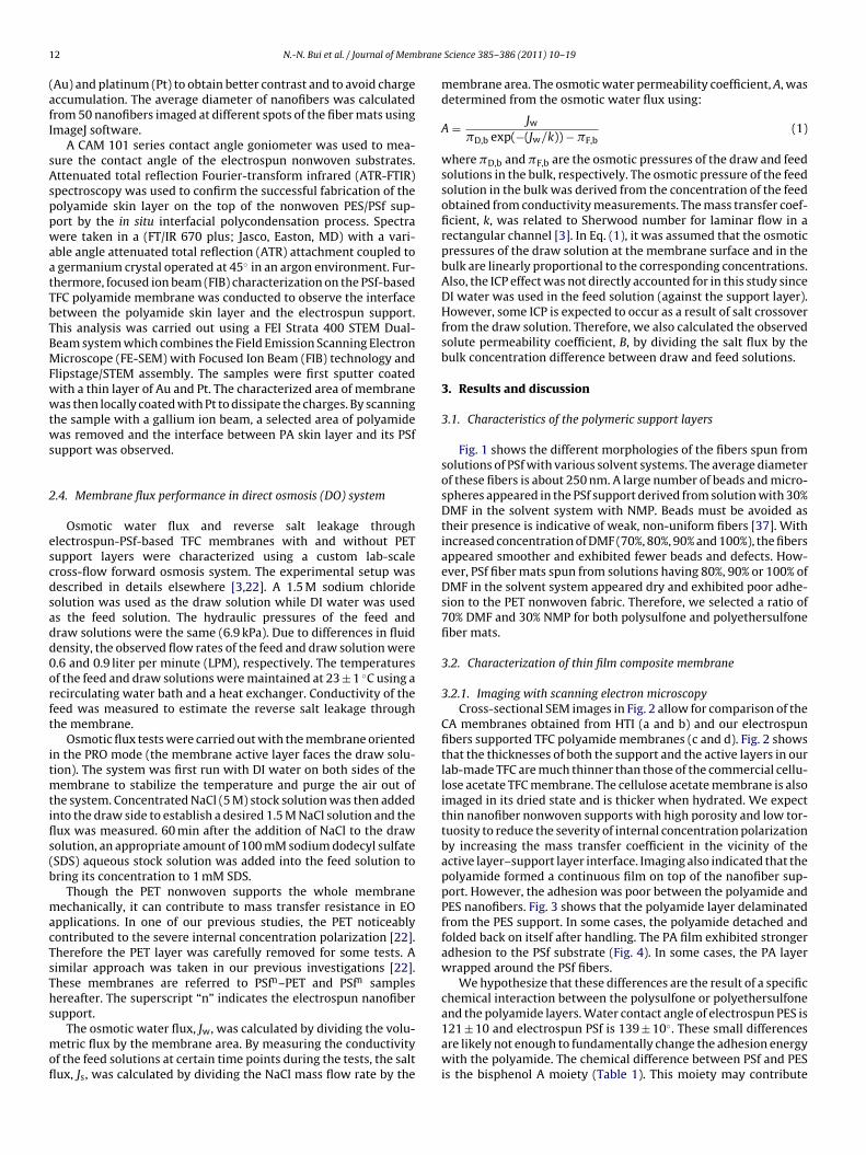
1 brane
(afI
sAsppwaatTbTBMFwwtws
2
escdsadd0orft
itmtifls(b
macTsThs
mofl
2 N.-N. Bui et al. / Journal of Mem
Au) and platinum (Pt) to obtain better contrast and to avoid chargeccumulation. The average diameter of nanofibers was calculatedrom 50 nanofibers imaged at different spots of the fiber mats usingmageJ software.
A CAM 101 series contact angle goniometer was used to mea-ure the contact angle of the electrospun nonwoven substrates.ttenuated total reflection Fourier-transform infrared (ATR-FTIR)pectroscopy was used to confirm the successful fabrication of theolyamide skin layer on the top of the nonwoven PES/PSf sup-ort by the in situ interfacial polycondensation process. Spectraere taken in a (FT/IR 670 plus; Jasco, Easton, MD) with a vari-
ble angle attenuated total reflection (ATR) attachment coupled to germanium crystal operated at 45◦ in an argon environment. Fur-hermore, focused ion beam (FIB) characterization on the PSf-basedFC polyamide membrane was conducted to observe the interfaceetween the polyamide skin layer and the electrospun support.his analysis was carried out using a FEI Strata 400 STEM Dual-eam system which combines the Field Emission Scanning Electronicroscope (FE-SEM) with Focused Ion Beam (FIB) technology and
lipstage/STEM assembly. The samples were first sputter coatedith a thin layer of Au and Pt. The characterized area of membraneas then locally coated with Pt to dissipate the charges. By scanning
he sample with a gallium ion beam, a selected area of polyamideas removed and the interface between PA skin layer and its PSf
upport was observed.
.4. Membrane flux performance in direct osmosis (DO) system
Osmotic water flux and reverse salt leakage throughlectrospun-PSf-based TFC membranes with and without PETupport layers were characterized using a custom lab-scaleross-flow forward osmosis system. The experimental setup wasescribed in details elsewhere [3,22]. A 1.5 M sodium chlorideolution was used as the draw solution while DI water was useds the feed solution. The hydraulic pressures of the feed andraw solutions were the same (6.9 kPa). Due to differences in fluidensity, the observed flow rates of the feed and draw solution were.6 and 0.9 liter per minute (LPM), respectively. The temperaturesf the feed and draw solutions were maintained at 23 ± 1 ◦C using aecirculating water bath and a heat exchanger. Conductivity of theeed was measured to estimate the reverse salt leakage throughhe membrane.
Osmotic flux tests were carried out with the membrane orientedn the PRO mode (the membrane active layer faces the draw solu-ion). The system was first run with DI water on both sides of the
embrane to stabilize the temperature and purge the air out ofhe system. Concentrated NaCl (5 M) stock solution was then addednto the draw side to establish a desired 1.5 M NaCl solution and theux was measured. 60 min after the addition of NaCl to the drawolution, an appropriate amount of 100 mM sodium dodecyl sulfateSDS) aqueous stock solution was added into the feed solution toring its concentration to 1 mM SDS.
Though the PET nonwoven supports the whole membraneechanically, it can contribute to mass transfer resistance in EO
pplications. In one of our previous studies, the PET noticeablyontributed to the severe internal concentration polarization [22].herefore the PET layer was carefully removed for some tests. Aimilar approach was taken in our previous investigations [22].hese membranes are referred to PSfn–PET and PSfn samplesereafter. The superscript “n” indicates the electrospun nanofiberupport.
The osmotic water flux, Jw, was calculated by dividing the volu-etric flux by the membrane area. By measuring the conductivity
f the feed solutions at certain time points during the tests, the saltux, Js, was calculated by dividing the NaCl mass flow rate by the
Science 385– 386 (2011) 10– 19
membrane area. The osmotic water permeability coefficient, A, wasdetermined from the osmotic water flux using:
A = Jw�D,b exp(−(Jw/k)) − �F,b
(1)
where �D,b and �F,b are the osmotic pressures of the draw and feedsolutions in the bulk, respectively. The osmotic pressure of the feedsolution in the bulk was derived from the concentration of the feedobtained from conductivity measurements. The mass transfer coef-ficient, k, was related to Sherwood number for laminar flow in arectangular channel [3]. In Eq. (1), it was assumed that the osmoticpressures of the draw solution at the membrane surface and in thebulk are linearly proportional to the corresponding concentrations.Also, the ICP effect was not directly accounted for in this study sinceDI water was used in the feed solution (against the support layer).However, some ICP is expected to occur as a result of salt crossoverfrom the draw solution. Therefore, we also calculated the observedsolute permeability coefficient, B, by dividing the salt flux by thebulk concentration difference between draw and feed solutions.
3. Results and discussion
3.1. Characteristics of the polymeric support layers
Fig. 1 shows the different morphologies of the fibers spun fromsolutions of PSf with various solvent systems. The average diameterof these fibers is about 250 nm. A large number of beads and micro-spheres appeared in the PSf support derived from solution with 30%DMF in the solvent system with NMP. Beads must be avoided astheir presence is indicative of weak, non-uniform fibers [37]. Withincreased concentration of DMF (70%, 80%, 90% and 100%), the fibersappeared smoother and exhibited fewer beads and defects. How-ever, PSf fiber mats spun from solutions having 80%, 90% or 100% ofDMF in the solvent system appeared dry and exhibited poor adhe-sion to the PET nonwoven fabric. Therefore, we selected a ratio of70% DMF and 30% NMP for both polysulfone and polyethersulfonefiber mats.
3.2. Characterization of thin film composite membrane
3.2.1. Imaging with scanning electron microscopyCross-sectional SEM images in Fig. 2 allow for comparison of the
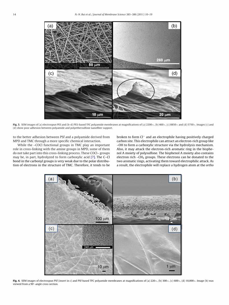
CA membranes obtained from HTI (a and b) and our electrospunfibers supported TFC polyamide membranes (c and d). Fig. 2 showsthat the thicknesses of both the support and the active layers in ourlab-made TFC are much thinner than those of the commercial cellu-lose acetate TFC membrane. The cellulose acetate membrane is alsoimaged in its dried state and is thicker when hydrated. We expectthin nanofiber nonwoven supports with high porosity and low tor-tuosity to reduce the severity of internal concentration polarizationby increasing the mass transfer coefficient in the vicinity of theactive layer–support layer interface. Imaging also indicated that thepolyamide formed a continuous film on top of the nanofiber sup-port. However, the adhesion was poor between the polyamide andPES nanofibers. Fig. 3 shows that the polyamide layer delaminatedfrom the PES support. In some cases, the polyamide detached andfolded back on itself after handling. The PA film exhibited strongeradhesion to the PSf substrate (Fig. 4). In some cases, the PA layerwrapped around the PSf fibers.
We hypothesize that these differences are the result of a specificchemical interaction between the polysulfone or polyethersulfoneand the polyamide layers. Water contact angle of electrospun PES is
121 ± 10 and electrospun PSf is 139 ± 10◦. These small differencesare likely not enough to fundamentally change the adhesion energywith the polyamide. The chemical difference between PSf and PESis the bisphenol A moiety (Table 1). This moiety may contribute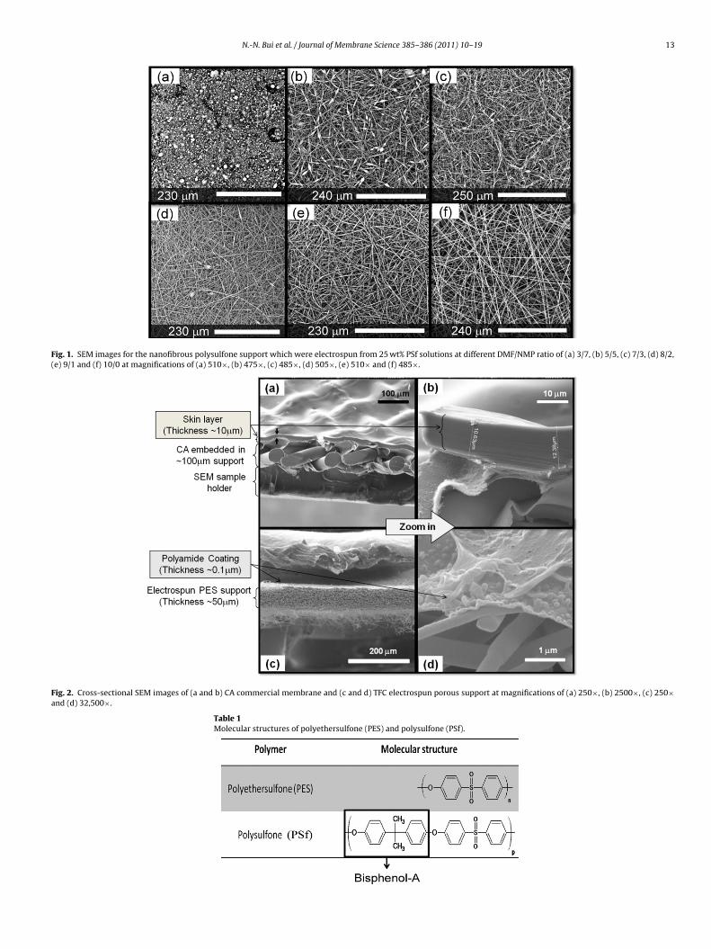
N.-N. Bui et al. / Journal of Membrane Science 385– 386 (2011) 10– 19 13
Fig. 1. SEM images for the nanofibrous polysulfone support which were electrospun from 25 wt% PSf solutions at different DMF/NMP ratio of (a) 3/7, (b) 5/5, (c) 7/3, (d) 8/2,(e) 9/1 and (f) 10/0 at magnifications of (a) 510×, (b) 475×, (c) 485×, (d) 505×, (e) 510× and (f) 485×.
Fig. 2. Cross-sectional SEM images of (a and b) CA commercial membrane and (c and d) TFC electrospun porous support at magnifications of (a) 250×, (b) 2500×, (c) 250×and (d) 32,500×.
Table 1Molecular structures of polyethersulfone (PES) and polysulfone (PSf).
14 N.-N. Bui et al. / Journal of Membrane Science 385– 386 (2011) 10– 19
F brane( rt.
tM
rdmbt
Fv
ig. 3. SEM images of (a) electrospun PES and (b–d) PES-based TFC polyamide memd) show poor adhesion between polyamide and polyethersulfone nanofiber suppo
o the better adhesion between PSf and a polyamide derived fromPD and TMC through a more specific chemical interaction.While the –COCl functional groups in TMC play an important
ole in cross-linking with the amine groups in MPD, some of them
o not take part into this cross-linking process. These COCl– groupsay be, in part, hydrolyzed to form carboxylic acid [7]. The C–Clond in the carbonyl groups is very weak due to the polar distribu-ion of electrons in the structure of TMC. Therefore, it tends to be
ig. 4. SEM images of electrospun PSf (insert in c) and PSf-based TFC polyamide membraiewed from a 90◦-angle cross section.
s at magnifications of (a) 2200×, (b) 460×, (c) 8850× and (d) 5750×. Images (c) and
broken to form Cl− and an electrophile having positively chargedcarbon site. This electrophile can attract an electron-rich group like–OH to form a carboxylic structure via the hydrolysis mechanism.Also, it may attack the electron-rich aromatic ring in the bisphe-
nol A moiety of polysulfone. The bisphenol A moiety also containselectron rich –CH3 groups. These electrons can be donated to thetwo aromatic rings, activating them toward electrophilic attack. Asa result, the electrophile will replace a hydrogen atom at the orthones at magnifications of (a) 220×, (b) 300×, (c) 600×, (d) 10,000×. Image (b) was

N.-N. Bui et al. / Journal of Membrane Science 385– 386 (2011) 10– 19 15
he bis
stmepttbpan
3
otPcbsbai1(ta
Fs
Fig. 5. Diagram of a possible cross-linking interaction between polyamide and t
ite of the aromatic ring via the electrophilic aromatic substitu-ion mechanism or, more specifically, the Friedel–Crafts acylation
echanism [38]. This mechanism can be catalyzed by the pres-nce of hydrochloric acid formed as a by-product of the interfacialolycondensation and the high temperature of about 95 ◦C used inhe post-formation rinses. The hypothesized cross-linking interac-ion between polyamide skin film and polysulfone substrate haseen shown in Fig. 5. It is important to note that the yield of thisroposed reaction mechanism need not be high to promote gooddhesion, since even a small number of covalent bonds would sig-ificantly enhance adhesion over Van der Waals forces.
.2.2. ATR-FTIR spectroscopy of supports and PA layersFig. 6 shows the ATR-FTIR spectra of the fingerprint region
f uncoated PES support and PA-coated PES. The IR spectrum ofhe composite samples is composed of bands attributed to bothA film and PES scaffold. Arrows indicate peaks specific to theomposite membrane. Peaks in both support and composite mem-rane between 1000 and 1400 cm−1 are characteristic of the PESupport [39]. Most new peaks appearing in the composite mem-rane are characteristic of the polyamide coating such as peakst 1661 cm−1 (C O of amide), 1610 cm−1 (aromatic ring breath-ng), and 1544 cm−1 (C–N stretch of amide II). Additional peaks at
−1 −1
450 cm and 1734 cm are due to the carboxylic acid groupsC–O stretching/O–H bending and C O stretching) [21,39]. In Fig. 7,he spectrum of the PA-coated membrane supported by PSf haslso displayed a strong band at 1650 cm−1 (amide I) which isig. 6. ATR-IR spectrum of PES nanofiber support (black curve) and PES nanofiber-upported TFC membrane (grey curve).
phenol A group of polysulfone. Arrows show the proposed reaction mechanism.
characteristic of C O band of an amide group. Furthermore,other bands characteristic of PA are also seen at 1610 cm−1 and1540 cm−1. Table 2 demonstrates a summary of probable assign-ments of IR bands for the PSf/PES–PA composite membrane surface.
3.2.3. Focused ion beam analysis on the PSf-based TFC membraneAn important advantage of using electrospun nanofiber mats as
a support for TFC membranes is their high surface porosity. Highsurface porosity increases the effective active area of the membraneby reducing the amount of the PA layer that is “masked” by the sup-port layer. Fig. 8 shows the PSf nanofiber supported TFC membrane.Removing the polyamide film with a focused ion beam exposedthe underlying mesh of nanofibers and their junctions. From theopen porous structures of the PSf layer, it can be seen that thereis an extremely high surface porosity of the underlying nanofibers.This ensures that a significant amount of the PA layer is exposedto the draw solute during forward osmosis. Fig. 8 also shows theextent to which the polyamide layer forms both on and aroundthe PSf nanofibers. The polyamide layer clearly mirrors the under-lying PSf nanofiber morphology underlying it while spanning thegaps between fibers (Fig. 8a and b). In Fig. 8c, the focused ion beamwas used to etch away a small area of the polyamide coating film,thus revealing the coating film layer to be less than 1 �m in thick-
ness, probably on the order of 400–500 nm. This further supportsimproved adhesion between the PA and PSf layers.Wavenumber (cm-1)
10001200140016001800
Abs
orba
nce
-0.01
0.00
0.01
0.02
0.03
Uncoated PSf supportPSf support coated with PA
Fig. 7. ATR-IR spectrum of the PSf nanofiber support (black curve) and PSf nanofibersupported TFC membrane (grey curve).

16 N.-N. Bui et al. / Journal of Membrane Science 385– 386 (2011) 10– 19
Fig. 8. Focused ion beam (FIB) images of polysulfone-supported thin film composite polyamide membrane at magnifications of (a) 3512× and (b and c) 19,995×.
Table 2Likely assignments of the IR spectra of the polyethersulfone, polysulfone, and polyamide-coated polyethersulfone/polysulfone composite membranes [21,39,50,51].
Spectra assignment Frequency (cm−1) Polymers
Skeletal aliphatic C–C/aromatic hydrogen bending/rocking 1072, 1108, 1014, 1080, 1106, 1169 PES, PSfSO2 symmetric stretch 1151 PES, PSfS O stretching and C–SO2–C asymmetric stretching 1294, 1325, 1295, 1323 PES, PSfAryl-O-aryl C–O stretch 1244 PES, PSfC C aromatic ring stretching 1418, 1410 PES, PSfCharacteristic of PES 1486 PESCH3–C–CH3 symmetric deformation 1365, 1385 PSfCH3–C–CH3 stretching 1488 PSfC C aromatic ring stretching 1502, 1586 PSfCarboxylic acid (C–O streching/O–H bending) 1450 PAC–N stretch (amide II) 1544 PAAromatic ring bending 1610 PAC O stretching (amide I) 1661 PAC O stretching (acid) 1734 PA
N.-N. Bui et al. / Journal of Membrane Science 385– 386 (2011) 10– 19 17
Table 3TFC polyamide membrane separation performance.
Observed waterflux (LMH) @�˘ = 76 bar
Observed salt flux(g/m2 h) @�C = 1.5 mol/l
Water permeability, A(m/kPa s)
Salt permeability, B(m/s)
Figure of merit,(A2/B) × 109
(m/kPa2 s)
PSfn–PET Before adding SDS 26.0 2.26 × 10⁻³ 1.74 × 10⁻⁹ 1.26 × 10⁻¹¹ 238.60After adding SDS 33.6 4.62 × 10⁻² 2.68 × 10⁻⁹ 3.08 × 10⁻¹⁰ 23.26
PSfn Before adding SDS 24.0 8.63 1.59 × 10⁻⁹ 4.79 × 10⁻⁸ 0.05
3
iPtoamtT
cTotpdmssmtbooph
Fbo1wtSdfa
After adding SDS 86.1 36.40
CA No SDS 15.5 1.13 × 10⁻¹
.3. Osmosis-driven flux
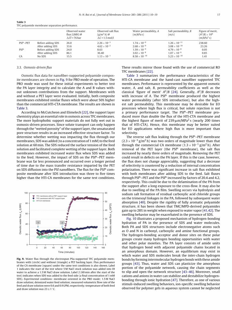
Osmotic flux data for nanofiber-supported polyamide compos-te membranes are shown in Fig. 9 for PRO mode of operation. TheRO mode was used for these initial experiments to better testhe PA layer integrity and to calculate the A and B values with-ut unknown contributions from the support. Membranes withnd without a PET layer were evaluated. Initially, both compositeembranes exhibited similar fluxes which were about 50% higher
han the commercial HTI-CTA membrane. The results are shown inable 3.
According to McCutcheon and Elimelech [22], the support layerhemistry plays an essential role in osmosis across TFC membranes.he more hydrophobic support materials do not fully wet out insmosis-driven processes. Since solute transport can only happenhrough the “wetted porosity” of the support layer, the unsaturatedore structure results in an increased effective structure factor. Toetermine whether wetting was impacting the flux through ourembranes, SDS was added (to a concentration of 1 mM) to the feed
olution at 60 min. The SDS reduced the surface tension of the feedolution and facilitated complete wetting of the support layer. Bothembranes exhibited increased water flux when SDS was added
o the feed. However, the impact of SDS on the PSfn–PET mem-rane was far less pronounced and occurred over a longer periodf time due to the mass transfer resistance imparted by the PET
n
n SDS diffusion into the PSf nanofibers. The flux for the PSf com-osite membrane after SDS introduction was three to five timesigher than the HTI-CA membranes for the same test conditions.Time ( minutes)
0 20 40 60 80 10 0 12 0 14 0 16 0
Osm
otic
wat
er fl
ux J
w (
LMH
)
0
20
40
60
80
100
Osm
otic
wat
er fl
ux J
w (
GF
D)
0
10
20
30
40
50
60
TFC membrane without PET s upport layer
TFC membrane with PE T s upport l ayer
HTI-CA memb rane
1 2
ig. 9. Water flux through the electrospun PSu-supported TFC polyamide mem-ranes with (circle) and without (triangle) a PET backing layer. Flux performancef the CA membrane (square) under the same test conditions is also shown. Label
indicates the start of the test where 5 M NaCl stock solution was added into DIater to achieve a 1.5 M NaCl draw solution. Label 2 (60 min after the start of the
est) indicates when SDS was added to the feed side (a final concentration of 1 mMDS). Experimental conditions: membrane oriented in the PRO mode; 1.5 M NaClraw solution; deionized water feed solution; measured volumetric flow rate of theeed and draw solution were 0.6 and 0.9 LPM, respectively; temperature of both feednd draw solution was 23 ± 1 ◦C.
3.02 × 10⁻⁸ 1.07 × 10⁻⁶ 0.858.58 × 10−10 5.23 × 10⁻¹⁰ 1.41
These results mirror those found with the use of commercial ROTFC membranes [22].
Table 3 summarizes the performance characteristics of theHTI-CA membrane and the hand-cast nanofiber supported TFCmembranes. Performance is represented by the apparent osmoticwater, A, and salt, B, permeability coefficients as well as theclassical ‘figure of merit’ A2/B [24]. Generally, A2/B decreaseswith increase of A. The PSfn membrane produced the highestwater permeability (after SDS introduction), but also the high-est salt permeability. This membrane may be desirable for EOprocesses where high flux is critical, but solute rejection is nota primary performance target. The PSfn–PET membrane pro-duced more than double the flux of the HTI-CTA membrane andthe highest figure of merit of 239 �m/MPa2 s (nearly 200 timesthat of HTI-CTA). Hence, this membrane may be better suitedfor EO applications where high flux is more important thanselectivity.
The reverse salt flux leaking through the PSfn–PET membrane(2.3 × 10⁻³ g/m2 h) was two orders of magnitude lower than thatthrough the commercial CA membrane (1.3 × 10⁻¹ g/m2 h). Afterremoval of the PET layer (the PSfn membrane), the salt fluxincreased by nearly three orders of magnitude. Removing the PETcould result in defects on the PA layer. If this is the case, however,the flux does not change appreciably, suggesting that a decreaseof selectivity is countered by a reduction of internal concentrationpolarization. There was significant increase in salt flux exhibitedwith both membranes after adding SDS to the feed. Salt fluxesthrough PSfn–PET and the PSfn increased by factors of 20.4 and 4.2,respectively. This could be due to the delamination of the PA fromthe support after a long exposure to the cross-flow. It may also bedue to swelling of the PA film. Swelling occurs via hydrolysis andsodium salt formation of residual carboxylic acid chloride groupson the trimesoyl linkages in the PA, followed by subsequent waterabsorption [40]. Despite the rigidity of fully aromatic polyamidestructure, it has been shown that TMC/MPD-derived polyamidesgain up to 28% in weight when exposed to water vapor [41,42]. Theswelling behavior may be exacerbated in the presence of SDS.
Fig. 10 illustrates a proposed mechanism of hydrogen-bondinghydration of PA in the presence of SDS and water molecules.Both PA and SDS structures include electronegative atoms suchas O and N in carbonyl, carboxylic and amine functional groups.The hydrogen-bonding acceptor and donor sites on these polargroups create many hydrogen bonding opportunities with waterand other polar moieties. The PA layer consists of amide unitsthat hydrogen bond with adjacent polyamide chains located inan amorphous domain. However, an equilibrium may exist inwhich water and SDS molecules break the inter-chain hydrogenbonds by forming intermolecular hydrogen bonds with these amidegroups [43]. Thus, water and SDS can plasticize the amorphousportion of the polyamide network, causing the chain segmentsto slip and open the network structure [43–46]. Moreover, small
cations and anions in water can stabilize and destabilize hydrogen-bonding through ionic hydration [47]. Therefore, as one of variousstimuli-induced swelling behaviors, ion-specific swelling behaviorobserved for polymer gels in aqueous system cannot be neglected
18 N.-N. Bui et al. / Journal of Membrane Science 385– 386 (2011) 10– 19
otted
[ehti
fdicPtbmetbat
4
iscpnomo
Fig. 10. Diagram of a possible arrangement of hydrogen-bonding hydration (d
47]. In the circumstance of using SDS as a wetting agent, the pres-nce of Na+ and Cl− may affect stabilization and destabilization ofydrogen-bonding hydration of polar polymers. As a consequence,he swelling of the polar polyamide skin layer may not be avoidablen the presence of SDS, NaCl, and water.
Moreover, SDS contacting with the back side of the PA layer mayurther contribute to plasticization. The PA layer is not a symmetricense film and in fact has dual density gradients above and below
ts dense middle layer. The result is non-uniform distribution ofrosslink density in the polyamide bulk [48,49]. The backside of theA layer likely has lower density, and thus, enables deeper pene-ration of SDS. Therefore, plasticization effects that are exacerbatedy ions may be enhanced. For example, the swelling mechanismay first occur at the edge of the membrane and gradually pen-
trate toward the dense inter-layer over time. Moreover, unlikeraditional TFC membranes, the polyamide layer in these mem-ranes has a less interfacial contact with the support membrane,nd hence, the polyamide layer may be more susceptible to swellinghan has traditionally been observed for TFC RO membranes.
. Conclusions
In this study, a polyamide film was successfully polymer-zed over an electrospun nanofiber nonwoven support providinguperior water flux and low salt flux for engineered osmosis appli-ations. This support structure was chosen because of its superiororosity and pore interconnectivity which results in reduced inter-
al concentration polarization. These novel membranes producedsmotic water fluxes two to five times higher than the com-ercial HTI-CTA osmotic membrane and compare favorably tother recently reported high flux osmotic membrane. While this
lines) of polyamide in the presence of sodium dodecyl sulfate (shaded areas).
departure from traditional polyamide composite membrane designshows immense promise as a next generation membrane platformfor engineered osmosis, further exploration of polymer chemistryand fabrication procedures is needed to optimize performance.Next generation membranes such as these may also generate newinsight into osmotic transport phenomenon and membranes tai-lored for specific engineered osmosis applications.
Acknowledgements
The authors acknowledge funding from the University ofConnecticut Research Foundation and Center for Environmen-tal Sciences and Engineering, Oasys Water®, The Department ofEnergy, and the UCLA California NanoSystems Institute. The authorsgraciously acknowledge Solvay Advanced Polymers for providingstock polymers for this work. Hydration Technologies Innovationsprovided the commercial cellulose acetate membrane for test com-parisons and Freudenberg provided the polyester nonwoven. Wealso thank Dr. Joysurya Basu and Professor Barry Carter at the Uni-versity of Connecticut for their assistance with the FIB SEM.
References
[1] R.L. McGinnis, M. Elimelech, Global challenges in energy and water supply: thepromise of engineered osmosis, Environ. Sci. Technol. 42 (2008) 8625–8629.
[2] T.Y. Cath, A.E. Childress, M. Elimelech, Forward osmosis: principles, applica-tions, and recent developments, J. Membr. Sci. 281 (2006) 70–87.
[3] J.R. McCutcheon, M. Elimelech, Influence of concentrative and dilutive internalconcentration polarization on flux behavior in forward osmosis, J. Membr. Sci.284 (2006) 237–247.
[4] G.T. Gray, J.R. McCutcheon, M. Elimelech, Internal concentration polarization inforward osmosis: role of membrane orientation, Desalination 197 (2006) 1–8.

brane
[
[
[
[
[
[
[
[
[
[
[
[
[
[
[
[
[
[
[
[
[
[
[
[
[
[
[
[
[
[
[
[
[
[
[
[[
[
[
[
N.-N. Bui et al. / Journal of Mem
[5] J.E. Cadotte, R.J. Petersen, Thin-film composite reverse-osmosis mem-branes: origin, development, and recent advances, Synth. Membr. 21 (1981)305–326.
[6] J.E. Cadotte, Reverse osmosis membrane, US Patent 4,259,183 (1981).[7] J.E. Cadotte, Interfacially synthesized reverse osmosis membrane, US Patent
4,277,344 (1981).[8] R.J. Petersen, J.E. Cadotte, Thin film composite reverse osmosis membranes,
in: M.C. Porter (Ed.), Handbook of Industrial Membrane Technology, NoyesPublications, NJ, 1988, pp. 307–348.
[9] M.L. Lind, A.K. Ghosh, A. Jawor, X. Huang, W. Hou, Y. Yang, E.M.V. Hoek, Influenceof zeolite crystal size on zeolite-polyamide thin film nanocomposite mem-branes, Langmuir 25 (2009) 10139–10145.
10] D. Mukherjee, A. Kulkarni, W.N. Gill, Chemical treatment for improved perfor-mance of reverse osmosis membranes, Desalination 104 (1996) 239–249.
11] M. Hirose, H. Ito, Y. Kamiyama, Effect of skin layer surface structures on the fluxbehavior of RO membranes, J. Membr. Sci. 121 (1996) 209–215.
12] I.J. Roh, S.Y. Park, J.J. Kim, C.K. Kim, Effects of the polyamide molecular structureon the performance of reverse osmosis membranes, J. Polym. Sci. Part B: Polym.Phys. 36 (1998) 1821–1830.
13] A. Kulkarni, D. Mukherjee, W.N. Gill, Flux enhancement by hydrophilizationof thin film composite reverse osmosis membranes, J. Membr. Sci. 114 (1996)39–50.
14] A.K. Ghosh, B.H. Jeong, X. Huang, E.M.V. Hoek, Impacts of reaction and curingconditions on polyamide composite reverse osmosis membrane properties, J.Membr. Sci. 311 (2008) 34–45.
15] A.K. Ghosh, E.M.V. Hoek, Impacts of support membrane structure and chemistryon polyamide–polysulfone interfacial composite membranes, J. Membr. Sci.336 (2009) 140–148.
16] B.H. Jeong, E.M.V. Hoek, Y. Yan, A. Subramani, X. Huang, G. Hurwitz, A.K. Ghosh,A. Jawor, Interfacial polymerization of thin film nanocomposites: a new conceptfor reverse osmosis membranes, J. Membr. Sci. 294 (2007) 1–7.
17] Y. Song, P. Sun, L.L. Henry, B. Sun, Mechanisms of structure and performancecontrolled thin film composite membrane formation via interfacial polymer-ization process, J. Membr. Sci. 251 (2005) 67–79.
18] V. Freger, J. Gilron, S. Belfer, TFC polyamide membranes modified by graftingof hydrophilic polymers: an FT-IR/AFM/TEM study, J. Membr. Sci. 209 (2002)283–292.
19] S. Belfer, Y. Purinson, R. Fainshtein, Y. Radchenko, O. Kedem, Surface modi-fication of commercial composite polyamide reverse osmosis membranes, J.Membr. Sci. 139 (1998) 175–181.
20] H.I. Kim, S.S. Kim, Plasma treatment of polypropylene and polysulfone supportsfor thin film composite reverse osmosis membrane, J. Membr. Sci. 286 (2006)193–201.
21] A.P. Rao, S.V. Joshi, J.J. Trivedi, C.V. Devmurari, V.J. Shah, Structure-performancecorrelation of polyamide thin film composite membranes: effect of coatingconditions on film formation, J. Membr. Sci. 221 (2003) 13–24.
22] J.R. McCutcheon, M. Elimelech, Influence of membrane support layer hydropho-bicity on water flux in osmotically driven membrane processes, J. Membr. Sci.318 (2008) 166–458.
23] K.L. Lee, R.W. Baker, H.K. Lonsdale, Membranes for power generation bypressure-retarded osmosis, J. Membr. Sci. 8 (1981) 141–171.
24] H.K. Lonsdale, Recent advances in reverse osmosis membranes, Desalination13 (1973) 317–332.
25] J.R. McCutcheon, M. Elimelech, Modeling water flux in forward osmosis: impli-cations for improved membrane design, AIChE J. 53 (2007) 1736–1744.
26] C.H. Tan, H.Y. Ng, Modified models to predict flux behavior in forward osmosis
in consideration of external and internal concentration polarizations, J. Membr.Sci. 324 (2008) 209–219.27] A. Achilli, T.Y. Cath, A.E. Childress, Power generation with pressure retardedosmosis: an experimental and theoretical investigation, J. Membr. Sci. 343(2009) 42–52.
[
[
Science 385– 386 (2011) 10– 19 19
28] A. Achilli, T.Y. Cath, A.E. Childress, Selection of inorganic-based draw solutionsfor forward osmosis applications, J. Membr. Sci. 364 (2010) 233–241.
29] A. Tiraferri, N.Y. Yip, W.A. Phillip, J.D. Schiffman, M. Elimelech, Relating perfor-mance of thin-film composite forward osmosis membranes to support layerformation and structure, J. Membr. Sci. 367 (2011) 340–352.
30] N.Y. Yip, A. Tiraferri, W.A. Phillip, J.D. Schiffman, M. Elimelech, High perfor-mance thin-film composite forward osmosis membrane, Environ. Sci. Technol.44 (2010) 3812–3818.
31] R. Wang, L. Shi, C.Y. Tang, S. Chou, C. Qiu, A.G. Fane, Characterization ofnovel forward osmosis hollow fiber membranes, J. Membr. Sci. 355 (2010)158–167.
32] J.T. Arena, B. McCloskey, B.D. Freeman, J.R. McCutcheon, Surface modificationof thin film composite membrane support layers with polydopamine: enablinguse of reverse osmosis membranes in pressure retarded osmosis, J. Membr. Sci.375 (2011) 55–62.
33] Z. Tang, C. Qiu, J.R. McCutcheon, K. Yoon, H. Ma, D. Fang, E. Lee, C. Kopp, B.S.Hsiao, B. Chu, Design and fabrication of electrospun polyethersulfone nanofi-brous scaffold for high-flux nanofiltration membranes, J. Polym. Sci. Part B:Polym. Phys. 47 (2009) 2288–2300.
34] P.H. Horward, Handbook of Environmental Fate and Exposure Data for OrganicChemicals, CRC Press, Boca Raton, FL, 1993.
35] K. Yoon, B.S. Hsiao, B. Chu, Formation of functional polyethersulfone elec-trospun membrane for water purification by mixed solvent and oxidationprocesses, Polymer 50 (2009) 2893–2899.
36] M.L. Lind, D.E. Suk, T.V. Nguyen, E.M.V. Hoek, Tailoring the structure of thin filmnanocomposite membranes to achieve seawater RO membrane performance,Environ. Sci. Technol. 44 (2010) 8230–8235.
37] Y. Liu, J.H. He, J.Y. Yu, H.M. Zeng, Controlling numbers and sizes of beads inelectrospun nanofibers, Polym. Int. 57 (2008) 632–636.
38] L.G. Wade, Reactions of aromatic compounds, in: Organic Chemistry, 5th ed.,Pearson Education Inc., NJ, 2003, 747 pp.
39] P.S. Singh, S.V. Joshi, J.J. Trivedi, C.V. Devmurari, A.P. Rao, P.K. Ghosh, Probingthe structural variations of thin film composite RO membranes obtained bycoating polyamide over polysulfone membranes of different pore dimensions,J. Membr. Sci. 278 (2006) 19–25.
40] J.E. Cadotte, R.S. King, R.J. Majerle, R.J. Petersen, Interfacial synthesis in thepreparation of reverse osmosis membrane, J. Macromol. Sci.-Chem. A15 (1981)727–755.
41] S.D. Arthur, Structure–property relationship in a thin film composite reverseosmosis membrane, J. Membr. Sci. 46 (1989) 243–260.
42] V. Freger, Swelling and morphology of the skin layer of polyamide compositemembranes: an atomic force microscopy study, Environ. Sci. Technol. 38 (2004)3168–3175.
43] H. Schott, Kinetics of swelling of polymers and their gels, J. Pharm. Sci. 81 (1992)467–470.
44] P.J. Flory, Principles of Polymer Chemistry, Cornell University Press, New York,1953.
45] N. Hirai, The Gel-Elasticity of High Polymers, Goto Laboratory, 1955, pp. 21–37.46] A.G. Tsuk, H.P. Gregor, Oleophilic ion-exchange polymers. II. Swelling of cross-
linked networks with multiple hetero side chains, J. Am. Chem. Soc. 87 (1965)5534–5537.
47] H. Muta, M. Miwa, M. Satoh, Ion-specific swelling of hydrophilic polymer gels,Polymer 42 (2001) 6313–6316.
48] V. Freger, Kinetics of film formation by interfacial polycondensation, Langmuir21 (2005) 1884–1894.
49] R. Nadler, S. Srebnik, Molecular simulation of polyamide synthesis by interfacial
polymerization, J. Membr. Sci. 315 (2008) 100–105.50] S. Salgin, S. Takac , T.H. Özdamar, Effect of ionic environments on the adsorptionand diffusion characteristics of serine alkaline protease enzyme in polyether-sulfone ultrafiltration membranes, J. Colloid Interface Sci. 299 (2006) 806–814.
51] J.E. Mark, Polymer Data Handbook, Oxford University Press, 1999.