
Journal of Materials Chemistry A - Case Western Reserve ...case.edu/cse/eche/daigroup/Journal...
20
Flexible supercapacitors based on carbon nanomaterials Tao Chen and Liming Dai * Flexible energy storage devices are essential for the development of flexible and wearable electronics. Flexible supercapacitors (also known as electrochemical capacitors or ultracapacitors) have attracted increasing attention for advanced energy storage because of their high capability, long cycle life, low cost, and easy fabrication. Carbon nanomaterials, including 1D carbon nanotubes, 2D graphene, and 3D mesoporous carbon, are promising as electrode materials for flexible supercapacitors due to their extremely large surface area, excellent mechanical and electrical properties, and high electrochemical stability. Much effort has been devoted to developing flexible, carbon-based, all-solid-state supercapacitors with different structure/performance characteristics, including conventional planar, ultrathin in-plane, wearable fiber-shaped, stretchable, transparent, and integrated devices with aesthetic appeal. The aim of this article is to provide an overview of recent progress towards the development of advanced flexible supercapacitors based on carbon nanomaterials. The challenges and perspectives in this emerging field are also discussed. 1 Introduction 1.1 Background of electrochemical capacitors The increasing depletion of fossil fuels and the environmental problems associated with their use have inspired the develop- ment of new types of clean and sustainable energy conversion systems (e.g., solar, wind, and water splitting) as new power sources with low exhaust emissions for transportation and stationary applications. As these new energy forms are oen limited by time (e.g., solar and wind) or region (e.g., water), energy storage systems, such as supercapacitors (also known as electrochemical capacitors or ultracapacitors) and batteries, are required to ensure continued and balanced power supplies. Although supercapacitors possess a relatively low energy density with respect to batteries (e.g., lithium-ion batteries), super- capacitors have received intensive attention for decades due to Tao Chen is currently a post- doctoral fellow in the Depart- ment of Macromolecular Science and Engineering at CWRU. He received his BS and MS in the Science of Polymer Materials from Zhengzhou University in 2006 and 2009, respectively, and received a PhD in Macro- molecular Chemistry and Physics from Fudan University in 2012. His research interests focus on the design and fabri- cation of carbon nanomaterials for exible, wearable and stretchable energy conversion, storage and their integrated devices. Liming Dai joined CWRU in 2009 as the Kent Hale Smith Professor in the Department of Macromolecular Science and Engineering. He is also director of Case4Carbon. He received a BSc from Zhejiang University in 1983 and a PhD from the Australian National University in 1991. He was a postdoctoral fellow at the University of Cam- bridge, a visiting fellow at the University of Illinois, and spent 10 years with CSIRO in Australia. He was a professor at the University of Akron and at the University of Dayton. His expertise is the synthesis, chemical modication, and device fabrication of conjugated polymers and carbon nanomaterials for energy and bio-related applications. Center of Advanced Science and Engineering for Carbon (Case4Carbon), Department of Macromolecular Science and Engineering, Case Western Reserve University, 10900 Euclid Avenue, Cleveland, OH 44106, USA. E-mail: [email protected] Cite this: DOI: 10.1039/c4ta00567h Received 31st January 2014 Accepted 24th February 2014 DOI: 10.1039/c4ta00567h www.rsc.org/MaterialsA This journal is © The Royal Society of Chemistry 2014 J. Mater. Chem. A Journal of Materials Chemistry A FEATURE ARTICLE Published on 26 February 2014. Downloaded by CASE WESTERN RESERVE UNIVERSITY on 28/04/2014 02:55:31. View Article Online View Journal
Transcript of Journal of Materials Chemistry A - Case Western Reserve ...case.edu/cse/eche/daigroup/Journal...
Journal ofMaterials Chemistry A
FEATURE ARTICLE
Publ
ishe
d on
26
Febr
uary
201
4. D
ownl
oade
d by
CA
SE W
EST
ER
N R
ESE
RV
E U
NIV
ER
SIT
Y o
n 28
/04/
2014
02:
55:3
1. View Article Online
View Journal
Flexible supercap
TdmarSf2amPif
cation of carbon nanomaterialsstretchable energy conversion, stora
Center of Advanced Science and Engineering
Macromolecular Science and Engineering,
Euclid Avenue, Cleveland, OH 44106, USA.
Cite this: DOI: 10.1039/c4ta00567h
Received 31st January 2014Accepted 24th February 2014
DOI: 10.1039/c4ta00567h
www.rsc.org/MaterialsA
This journal is © The Royal Society of
acitors based on carbonnanomaterials
Tao Chen and Liming Dai*
Flexible energy storage devices are essential for the development of flexible and wearable electronics.
Flexible supercapacitors (also known as electrochemical capacitors or ultracapacitors) have attracted
increasing attention for advanced energy storage because of their high capability, long cycle life, low
cost, and easy fabrication. Carbon nanomaterials, including 1D carbon nanotubes, 2D graphene, and 3D
mesoporous carbon, are promising as electrode materials for flexible supercapacitors due to their
extremely large surface area, excellent mechanical and electrical properties, and high electrochemical
stability. Much effort has been devoted to developing flexible, carbon-based, all-solid-state
supercapacitors with different structure/performance characteristics, including conventional planar,
ultrathin in-plane, wearable fiber-shaped, stretchable, transparent, and integrated devices with aesthetic
appeal. The aim of this article is to provide an overview of recent progress towards the development of
advanced flexible supercapacitors based on carbon nanomaterials. The challenges and perspectives in
this emerging field are also discussed.
1 Introduction1.1 Background of electrochemical capacitors
The increasing depletion of fossil fuels and the environmentalproblems associated with their use have inspired the develop-ment of new types of clean and sustainable energy conversion
ao Chen is currently a post-octoral fellow in the Depart-ent of Macromolecular Sciencend Engineering at CWRU. Heeceived his BS and MS in thecience of Polymer Materialsrom Zhengzhou University in006 and 2009, respectively,nd received a PhD in Macro-olecular Chemistry andhysics from Fudan Universityn 2012. His research interestsocus on the design and fabri-
for exible, wearable andge and their integrated devices.
for Carbon (Case4Carbon), Department of
Case Western Reserve University, 10900
E-mail: [email protected]
Chemistry 2014
systems (e.g., solar, wind, and water splitting) as new powersources with low exhaust emissions for transportation andstationary applications. As these new energy forms are oenlimited by time (e.g., solar and wind) or region (e.g., water),energy storage systems, such as supercapacitors (also known aselectrochemical capacitors or ultracapacitors) and batteries, arerequired to ensure continued and balanced power supplies.Although supercapacitors possess a relatively low energy densitywith respect to batteries (e.g., lithium-ion batteries), super-capacitors have received intensive attention for decades due to
Liming Dai joined CWRU in2009 as the Kent Hale SmithProfessor in the Department ofMacromolecular Science andEngineering. He is also directorof Case4Carbon. He received aBSc from Zhejiang University in1983 and a PhD from theAustralian National Universityin 1991. He was a postdoctoralfellow at the University of Cam-bridge, a visiting fellow at theUniversity of Illinois, and spent
10 years with CSIRO in Australia. He was a professor at theUniversity of Akron and at the University of Dayton. His expertiseis the synthesis, chemical modication, and device fabrication ofconjugated polymers and carbon nanomaterials for energy andbio-related applications.
J. Mater. Chem. A
Journal of Materials Chemistry A Feature Article
Publ
ishe
d on
26
Febr
uary
201
4. D
ownl
oade
d by
CA
SE W
EST
ER
N R
ESE
RV
E U
NIV
ER
SIT
Y o
n 28
/04/
2014
02:
55:3
1.
View Article Online
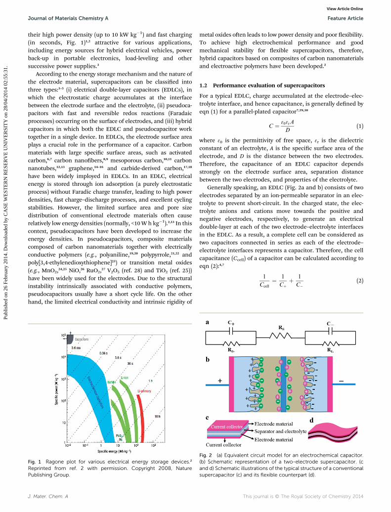
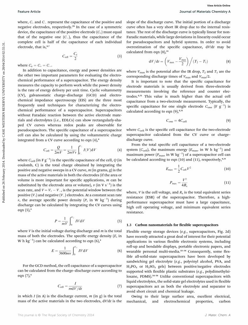
their high power density (up to 10 kW kg�1) and fast charging(in seconds, Fig. 1)1,2 attractive for various applications,including energy sources for hybrid electrical vehicles, powerback-up in portable electronics, load-leveling and othersuccessive power supplies.3
According to the energy storage mechanism and the nature ofthe electrode material, supercapacitors can be classied intothree types:3–5 (i) electrical double-layer capacitors (EDLCs), inwhich the electrostatic charge accumulates at the interfacebetween the electrode surface and the electrolyte, (ii) pseudoca-pacitors with fast and reversible redox reactions (Faradaicprocesses) occurring on the surface of electrodes, and (iii) hybridcapacitors in which both the EDLC and pseudocapacitor worktogether in a single device. In EDLCs, the electrode surface areaplays a crucial role in the performance of a capacitor. Carbonmaterials with large specic surface areas, such as activatedcarbon,6,7 carbon nanobers,8,9 mesoporous carbon,10,11 carbonnanotubes,12,13 graphene,14–16 and carbide-derived carbon,17,18
have been widely imployed in EDLCs. In an EDLC, electricalenergy is stored through ion adsorption (a purely electrostaticprocess) without Faradic charge transfer, leading to high powerdensities, fast charge–discharge processes, and excellent cyclingstabilities. However, the limited surface area and pore sizedistribution of conventional electrode materials oen causerelatively low energy densities (normally, <10W h kg�1).2,13 In thiscontext, pseudocapacitors have been developed to increase theenergy densities. In pseudocapacitors, composite materialscomposed of carbon nanomaterials together with electricallyconductive polymers (e.g., polyaniline,19,20 polypyrrole,21,22 andpoly[3,4-ethylenedioxythiophene]23) or transition metal oxides(e.g., MnO2,24,25 NiO,26 RuO2,27 V2O5 (ref. 28) and TiO2 (ref. 25))have been widely used for the electrodes. Due to the structuralinstability intrinsically associated with conductive polymers,pseudocapacitors usually have a short cycle life. On the otherhand, the limited electrical conductivity and intrinsic rigidity of
Fig. 1 Ragone plot for various electrical energy storage devices.2
Reprinted from ref. 2 with permission. Copyright 2008, NaturePublishing Group.
J. Mater. Chem. A
metal oxides oen leads to low power density and poor exibility.To achieve high electrochemical performance and goodmechanical stability for exible supercapacitors, therefore,hybrid capacitors based on composites of carbon nanomaterialsand electroactive polymers have been developed.2
1.2 Performance evaluation of supercapacitors
For a typical EDLC, charge accumulated at the electrode–elec-trolyte interface, and hence capacitance, is generally dened byeqn (1) for a parallel-plated capacitor7,29,30
C ¼ 303rA
D(1)
where 30 is the permittivity of free space, 3r is the dielectricconstant of an electrolyte, A is the specic surface area of theelectrode, and D is the distance between the two electrodes.Therefore, the capacitance of an EDLC capacitor dependsstrongly on the electrode surface area, separation distancebetween the two electrodes, and properties of the electrolyte.
Generally speaking, an EDLC (Fig. 2a and b) consists of twoelectrodes separated by an ion-permeable separator in an elec-trolyte to prevent short-circuit. In the charged state, the elec-trolyte anions and cations move towards the positive andnegative electrodes, respectively, to generate an electricaldouble-layer at each of the two electrode–electrolyte interfacesin the EDLC. As a result, a complete cell can be considered astwo capacitors connected in series as each of the electrode–electrolyte interfaces represents a capacitor. Therefore, the cellcapacitance (Ccell) of a capacitor can be calculated according toeqn (2):4,7
1
Ccell
¼ 1
Cþþ 1
C�(2)
Fig. 2 (a) Equivalent circuit model for an electrochemical capacitor.(b) Schematic representation of a two-electrode supercapacitor. (cand d) Schematic illustrations of the typical structure of a conventionalsupercapacitor (c) and its flexible counterpart (d).
This journal is © The Royal Society of Chemistry 2014
Feature Article Journal of Materials Chemistry A
Publ
ishe
d on
26
Febr
uary
201
4. D
ownl
oade
d by
CA
SE W
EST
ER
N R
ESE
RV
E U
NIV
ER
SIT
Y o
n 28
/04/
2014
02:
55:3
1.
View Article Online
where, C+ and C� represent the capacitance of the positive andnegative electrodes, respectively.29 In the case of a symmetricdevice, the capacitance of the positive electrode (C+) must equalthat of the negative one (C�), thus the capacitance of thecomplete cell is half of the capacitance of each individualelectrode, that is,4,7
Ccell ¼ Ce
2(3)
where Ce ¼ C+ ¼ C�.In addition to capacitance, energy and power densities are
the other two important parameters for evaluating the electro-chemical performance of a supercapacitor. The energy densitymeasures the capacity to perform work while the power densityis the rate of energy delivery per unit time. Cyclic voltammetry(CV), galvanostatic charge–discharge (GCD) and electro-chemical impedance spectroscopy (EIS) are the three mostfrequently used techniques for characterizing the electro-chemical performance of a supercapacitor. Supercapacitorswithout Faradaic reaction between the active electrode mate-rials and electrolytes (i.e., EDLCs) can show rectangularly-sha-ped CV curves whereas redox peaks are observable forpseudocapacitors. The specic capacitance of a supercapacitorcell can also be calculated by using the voltammetric chargeintegrated from a CV curve according to eqn (4),4
Ccell ¼ Q
2mV¼ 1
2mVv
ðVþ
V�IðVÞdV (4)
where Ccell (in F g�1) is the specic capacitance of the cell, Q (incoulomb, C) is the total charge obtained by integrating thepositive and negative sweeps in a CV curve,m (in grams, g) is themass of the active materials in both the electrodes (if the area orvolume is more important for specic applications, m can besubstituted by the electrode area or volume), v (in V s�1) is thescan rate, and V ¼ V+ � V�, is the potential window between thepositive (V+) and negative (V�) electrodes. At a constant scan raten, the average specic power density (P, in W kg�1) duringdischarge can be calculated by integrating the CV curves usingeqn (5),4
P ¼ 1
mV
ðVþ
0
IVdV (5)
where V is the initial voltage during discharge and m is the totalmass of both the electrodes. The specic energy density (E, inW h kg�1) can be calculated according to eqn (6),4
E ¼ 1
3600mv
ðVþ
0
IVdV (6)
For the GCDmethod, the cell capacitance of a supercapacitorcan be calculated from the charge–discharge curve according toeqn (7),4
Ccell ¼ I
mdV=dt(7)
in which I (in A) is the discharge current, m (in g) is the totalmass of the active materials in the two electrodes, dV/dt is the
This journal is © The Royal Society of Chemistry 2014
slope of the discharge curve. The initial portion of a dischargecurve oen has a very short IR drop due to the internal resis-tance. The rest of the discharge curve is typically linear for non-Faradic materials, while large deviations in linearity could occurfor pseudocapacitors and hybrid systems. In order to avoidoverestimation of the specic capacitance, dV/dt may becalculated from eqn (8),31
dV=dt ¼�Vmax � Vmax
2
�ðT2 � T1Þ
�(8)
where Vmax is the potential aer the IR drop, T2 and T1 are thecorresponding discharge times of Vmax and Vmax/2.
It is important to note that the specic capacitance forelectrode materials is usually derived from three-electrodemeasurements involving the reference and counter elec-trodes.4,31 This value is much higher than the actual cellcapacitance from a two-electrode measurement. Typically, thespecic capacitance for one single electrode Cone (F g�1) iscalculated according to eqn (9),4,31
Cone ¼ 4Ccell (9)
where Ccell is the specic cell capacitance for the two-electrodesupercapacitor calculated from the CV curve or charge–discharge curve.
From the total specic cell capacitance of a two-electrodesystem (Ccell), the maximum energy (Emax, in W h kg�1) andmaximum power (Pmax, in W kg�1) of a supercapacitor cell canbe calculated according to eqn (10) and (11), respectively,4,31
Emax ¼ 1
2CcellV
2 (10)
Pmax ¼ V 2
4Rs
(11)
where, V is the cell voltage, and Rs is the total equivalent seriesresistance (ESR) of the supercapacitor. Therefore, a high-performance supercapacitor must have a large capacitance,high cell operating voltage, and minimum equivalent seriesresistance.
1.3 Carbon nanomaterials for exible supercapacitors
Flexible energy storage devices (e.g., supercapacitors, Fig. 2d)have recently attracted a great deal of interest for their potentialapplications in various exible electronic systems, includingroll-up and bendable displays, portable electronic papers, andwearable personal multi-media.32–34 Consequently, some ex-ible all-solid-state supercapacitors have been developed bysandwiching gel electrolyte (e.g., polyvinyl alcohol, PVA, andH3PO4 or H2SO4 gels) between positive/negative electrodessupported with exible plastic substrates (e.g., polydimethylsi-loxane, PDMS).34–36 Unlike conventional supercapacitors withliquid electrolytes, the solid-state gel electrolytes used in exiblesupercapacitors act as both the electrolyte and separator toavoid short circuit and chemical leakage.
Owing to their large surface area, excellent electrical,mechanical, and electrochemical properties, carbon
J. Mater. Chem. A
Journal of Materials Chemistry A Feature Article
Publ
ishe
d on
26
Febr
uary
201
4. D
ownl
oade
d by
CA
SE W
EST
ER
N R
ESE
RV
E U
NIV
ER
SIT
Y o
n 28
/04/
2014
02:
55:3
1.
View Article Online
nanomaterials (especially, carbon nanotubes, CNTs, and gra-phene sheets) have been widely used as active materials/elec-trodes in (exible) supercapacitors.13,34,37–39 These earlier studieshave demonstrated that carbon nanomaterials are promisingfor the development of supercapacitors in general and exiblesupercapacitors in particular. Several recent reviews for super-capacitors based on carbon nanomaterials have appeared,34,38–40
and interested readers can obtain more detailed informationfrom appropriate references cited for various specic carbonelectrodes, including carbon nanomaterials,5,13,15,16,40,41 porouscarbon,42 conductive polymers,43,44 and 3D nanostructuredcarbon.39 However, the progresses on carbon-based exiblesupercapacitors has been much less discussed in the litera-ture.34 The aim of this article is to provide a comprehensivereview of various newly-developed exible all-solid-state super-capacitors based on carbon nanomaterials (Fig. 3), including in-plane,45 ber-shaped,46 stretchable,47 transparent and inte-grated supercapacitors.48 In what follows, we rst describenanocarbon-based exible (micro-) supercapacitors with planarstructures. Then, we illustrate wearable ber-shaped super-capacitors based on carbon nanomaterials, followed by carbon-based stretchable and transparent supercapacitors. Finally,exible supercapacitors integrated with other energy deviceswill be discussed, along with challenges and perspectives in thisemerging eld.
2 Nanocarbon-based flexiblesupercapacitors with planar structures
The 1D CNTs and 2D graphene represent two of the mostextensively exploited carbon allotropes for electrochemicalenergy storage.33,34 High-performance exible supercapacitorswith planar structures based on CNT, graphene, and theirhybrid electrodes have been developed, and are the subject ofthis section.
2.1 CNT-based exible supercapacitors
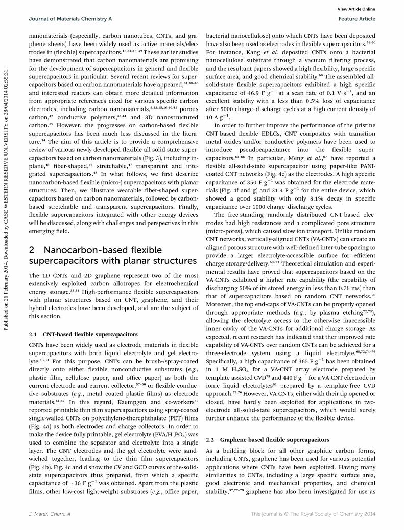
CNTs have been widely used as electrode materials in exiblesupercapacitors with both liquid electrolyte and gel electro-lyte.13,33 For this purpose, CNTs can be brush-/spray-coateddirectly onto either exible nonconductive substrates (e.g.,plastic lm, cellulose paper, and office paper) as both thecurrent electrode and current collector,57–60 or exible conduc-tive substrates (e.g., metal coated plastic lms) as electrodematerials.61,62 In this regard, Kaempgen and co-workers57
reported printable thin lm supercapacitors using spray-coatedsingle-walled CNTs on polyethylene-therephthalate (PET) lms(Fig. 4a) as both electrodes and charge collectors. In order tomake the device fully printable, gel electrolyte (PVA/H3PO4) wasused to combine the separator and electrolyte into a singlelayer. The CNT electrodes and the gel electrolyte were sand-wiched together, leading to the thin lm supercapacitors(Fig. 4b). Fig. 4c and d show the CV and GCD curves of the-solid-state supercapacitors thus prepared, from which a speciccapacitance of �36 F g�1 was obtained. Apart from the plasticlms, other low-cost light-weight substrates (e.g., office paper,
J. Mater. Chem. A
bacterial nanocellulose) onto which CNTs have been depositedhave also been used as electrodes in exible supercapacitors.59,60
For instance, Kang et al. deposited CNTs onto a bacterialnanocellulose substrate through a vacuum ltering process,and the resultant papers showed a high exibility, large specicsurface area, and good chemical stability.60 The assembled all-solid-state exible supercapacitors exhibited a high speciccapacitance of 46.9 F g�1 at a scan rate of 0.1 V s�1, and anexcellent stability with a less than 0.5% loss of capacitanceaer 5000 charge–discharge cycles at a high current density of10 A g�1.
In order to further improve the performance of the pristineCNT-based exible EDLCs, CNT composites with transitionmetal oxides and/or conductive polymers have been used tointroduce pseudocapacitance into the exible super-capacitors.63–66 In particular, Meng et al.,67 have reported aexible all-solid-state supercapacitor using paper-like PANI-coated CNT networks (Fig. 4e) as the electrodes. A high speciccapacitance of 350 F g�1 was obtained for the electrode mate-rials (Fig. 4f and g) and 31.4 F g�1 for the entire device, whichshowed a good stability with only 8.1% decay in speciccapacitance over 1000 charge–discharge cycles.
The free-standing randomly distributed CNT-based elec-trodes had high resistances and a complicated pore structure(micro-pores), which caused slow ion transport. Unlike randomCNT networks, vertically-aligned CNTs (VA-CNTs) can create analigned porous structure with well-dened inter-tube spacing toprovide a larger electrolyte-accessible surface for efficientcharge storage/delivery.68–71 Theoretical simulation and experi-mental results have proved that supercapacitors based on theVA-CNTs exhibited a higher rate capability (the capability ofdischarging 50% of its stored energy in less than 0.76 ms) thanthat of supercapacitors based on random CNT networks.70
Moreover, the top end-caps of VA-CNTs can be properly openedthrough appropriate methods (e.g., by plasma etching72,73),allowing the electrolyte access to the otherwise inaccessibleinner cavity of the VA-CNTs for additional charge storage. Asexpected, recent research has indicated that ther improved ratecapability of VA-CNTs over random CNTs can be achieved for athree-electrode system using a liquid electrolyte.68,72,74–76
Specically, a high capacitance of 365 F g�1 has been obtainedin 1 M H2SO4 for a VA-CNT array electrode prepared bytemplate-assisted CVD75 and 440 F g�1 for a VA-CNT electrode inionic liquid electrolytes62 prepared by a template-free CVDapproach.72,76 However, VA-CNTs, either with their tip opened orclosed, have hardly been exploited for applications in two-electrode all-solid-state supercapacitors, which would surelyfurther enhance the performance of the exible device.
2.2 Graphene-based exible supercapacitors
As a building block for all other graphitic carbon forms,including CNTs, graphene has been used for various potentialapplications where CNTs have been exploited. Having manysimilarities to CNTs, including a large specic surface area,good electronic and mechanical properties, and chemicalstability,37,77–79 graphene has also been investigated for use as
This journal is © The Royal Society of Chemistry 2014
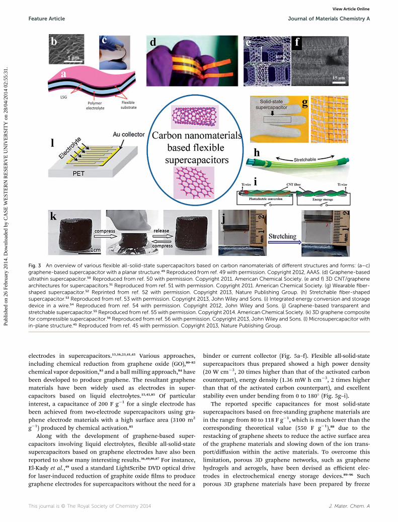
Fig. 3 An overview of various flexible all-solid-state supercapacitors based on carbon nanomaterials of different structures and forms: (a–c)graphene-based supercapacitor with a planar structure.49 Reproduced from ref. 49 with permission. Copyright 2012, AAAS. (d) Graphene-basedultrathin supercapacitor.50 Reproduced from ref. 50 with permission. Copyright 2011. American Chemical Society. (e and f) 3D CNT/graphenearchitectures for supercapacitors.51 Reproduced from ref. 51 with permission. Copyright 2011. American Chemical Society. (g) Wearable fiber-shaped supercapacitor.52 Reprinted from ref. 52 with permission. Copyright 2013, Nature Publishing Group. (h) Stretchable fiber-shapedsupercapacitor.53 Reproduced from ref. 53 with permission. Copyright 2013, John Wiley and Sons. (i) Integrated energy conversion and storagedevice in a wire.54 Reproduced from ref. 54 with permission. Copyright 2012, John Wiley and Sons. (j) Graphene-based transparent andstretchable supercapacitor.55 Reproduced from ref. 55 with permission. Copyright 2014. American Chemical Society. (k) 3D graphene compositefor compressible supercapacitor.56 Reproduced from ref. 56 with permission. Copyright 2013, John Wiley and Sons. (l) Microsupercapacitor within-plane structure.45 Reproduced from ref. 45 with permission. Copyright 2013, Nature Publishing Group.
Feature Article Journal of Materials Chemistry A
Publ
ishe
d on
26
Febr
uary
201
4. D
ownl
oade
d by
CA
SE W
EST
ER
N R
ESE
RV
E U
NIV
ER
SIT
Y o
n 28
/04/
2014
02:
55:3
1.
View Article Online
electrodes in supercapacitors.15,16,23,41,45 Various approaches,including chemical reduction from graphene oxide (GO),80–82
chemical vapor deposition,83 and a ball milling approach,84 havebeen developed to produce graphene. The resultant graphenematerials have been widely used as electrodes in super-capacitors based on liquid electrolytes.15,41,85 Of particularinterest, a capacitance of 200 F g�1 for a single electrode hasbeen achieved from two-electrode supercapacitors using gra-phene electrode materials with a high surface area (3100 m2
g�1) produced by chemical activation.85
Along with the development of graphene-based super-capacitors involving liquid electrolytes, exible all-solid-statesupercapacitors based on graphene electrodes have also beenreported to show many interesting results.36,49,86,87 For instance,El-Kady et al.,49 used a standard LightScribe DVD optical drivefor laser-induced reduction of graphite oxide lms to producegraphene electrodes for supercapacitors without the need for a
This journal is © The Royal Society of Chemistry 2014
binder or current collector (Fig. 5a–f). Flexible all-solid-statesupercapacitors thus prepared showed a high power density(20 W cm�3, 20 times higher than that of the activated carboncounterpart), energy density (1.36 mW h cm�3, 2 times higherthan that of the activated carbon counterpart), and excellentstability even under bending from 0 to 180� (Fig. 5g–i).
The reported specic capacitances for most solid-statesupercapacitors based on free-standing graphene materials arein the range from 80 to 118 F g�1, which is much lower than thecorresponding theoretical value (550 F g�1),88 due to therestacking of graphene sheets to reduce the active surface areaof the graphene materials and slowing down of the ion trans-port/diffusion within the active materials. To overcome thislimitation, porous 3D graphene networks, such as graphenehydrogels and aerogels, have been devised as efficient elec-trodes in electrochemical energy storage devices.89–96 Suchporous 3D graphene materials have been prepared by freeze
J. Mater. Chem. A
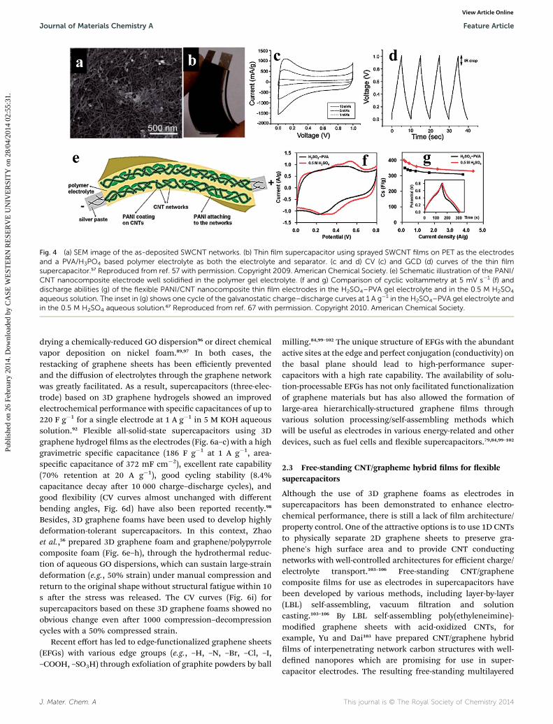
Fig. 4 (a) SEM image of the as-deposited SWCNT networks. (b) Thin film supercapacitor using sprayed SWCNT films on PET as the electrodesand a PVA/H3PO4 based polymer electrolyte as both the electrolyte and separator. (c and d) CV (c) and GCD (d) curves of the thin filmsupercapacitor.57 Reproduced from ref. 57 with permission. Copyright 2009. American Chemical Society. (e) Schematic illustration of the PANI/CNT nanocomposite electrode well solidified in the polymer gel electrolyte. (f and g) Comparison of cyclic voltammetry at 5 mV s�1 (f) anddischarge abilities (g) of the flexible PANI/CNT nanocomposite thin film electrodes in the H2SO4–PVA gel electrolyte and in the 0.5 M H2SO4
aqueous solution. The inset in (g) shows one cycle of the galvanostatic charge–discharge curves at 1 A g�1 in the H2SO4–PVA gel electrolyte andin the 0.5 M H2SO4 aqueous solution.67 Reproduced from ref. 67 with permission. Copyright 2010. American Chemical Society.
Journal of Materials Chemistry A Feature Article
Publ
ishe
d on
26
Febr
uary
201
4. D
ownl
oade
d by
CA
SE W
EST
ER
N R
ESE
RV
E U
NIV
ER
SIT
Y o
n 28
/04/
2014
02:
55:3
1.
View Article Online
drying a chemically-reduced GO dispersion96 or direct chemicalvapor deposition on nickel foam.89,97 In both cases, therestacking of graphene sheets has been efficiently preventedand the diffusion of electrolytes through the graphene networkwas greatly facilitated. As a result, supercapacitors (three-elec-trode) based on 3D graphene hydrogels showed an improvedelectrochemical performance with specic capacitances of up to220 F g�1 for a single electrode at 1 A g�1 in 5 M KOH aqueoussolution.92 Flexible all-solid-state supercapacitors using 3Dgraphene hydrogel lms as the electrodes (Fig. 6a–c) with a highgravimetric specic capacitance (186 F g�1 at 1 A g�1, area-specic capacitance of 372 mF cm�2), excellent rate capability(70% retention at 20 A g�1), good cycling stability (8.4%capacitance decay aer 10 000 charge–discharge cycles), andgood exibility (CV curves almost unchanged with differentbending angles, Fig. 6d) have also been reported recently.98
Besides, 3D graphene foams have been used to develop highlydeformation-tolerant supercapacitors. In this context, Zhaoet al.,56 prepared 3D graphene foam and graphene/polypyrrolecomposite foam (Fig. 6e–h), through the hydrothermal reduc-tion of aqueous GO dispersions, which can sustain large-straindeformation (e.g., 50% strain) under manual compression andreturn to the original shape without structural fatigue within 10s aer the stress was released. The CV curves (Fig. 6i) forsupercapacitors based on these 3D graphene foams showed noobvious change even aer 1000 compression–decompressioncycles with a 50% compressed strain.
Recent effort has led to edge-functionalized graphene sheets(EFGs) with various edge groups (e.g., –H, –N, –Br, –Cl, –I,–COOH, –SO3H) through exfoliation of graphite powders by ball
J. Mater. Chem. A
milling.84,99–102 The unique structure of EFGs with the abundantactive sites at the edge and perfect conjugation (conductivity) onthe basal plane should lead to high-performance super-capacitors with a high rate capability. The availability of solu-tion-processable EFGs has not only facilitated functionalizationof graphene materials but has also allowed the formation oflarge-area hierarchically-structured graphene lms throughvarious solution processing/self-assembling methods whichwill be useful as electrodes in various energy-related and otherdevices, such as fuel cells and exible supercapacitors.79,84,99–102
2.3 Free-standing CNT/grapheme hybrid lms for exiblesupercapacitors
Although the use of 3D graphene foams as electrodes insupercapacitors has been demonstrated to enhance electro-chemical performance, there is still a lack of lm architecture/property control. One of the attractive options is to use 1D CNTsto physically separate 2D graphene sheets to preserve gra-phene's high surface area and to provide CNT conductingnetworks with well-controlled architectures for efficient charge/electrolyte transport.103–106 Free-standing CNT/graphenecomposite lms for use as electrodes in supercapacitors havebeen developed by various methods, including layer-by-layer(LBL) self-assembling, vacuum ltration and solutioncasting.103–106 By LBL self-assembling poly(ethyleneimine)-modied graphene sheets with acid-oxidized CNTs, forexample, Yu and Dai103 have prepared CNT/graphene hybridlms of interpenetrating network carbon structures with well-dened nanopores which are promising for use in super-capacitor electrodes. The resulting free-standing multilayered
This journal is © The Royal Society of Chemistry 2014
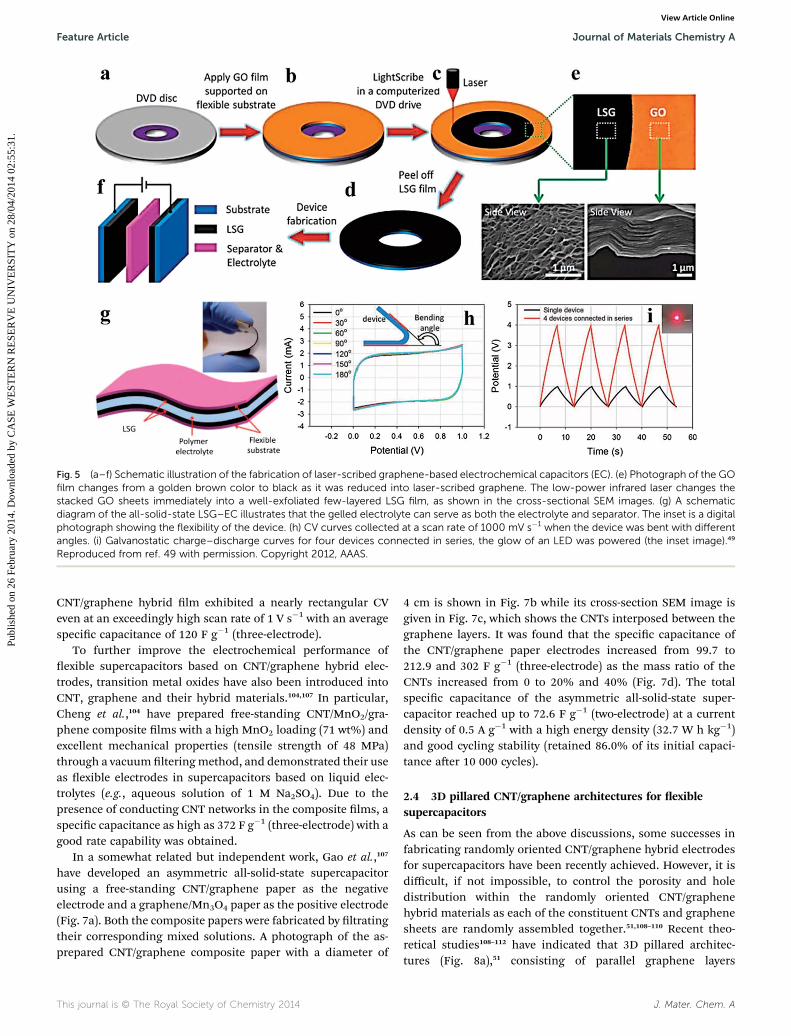
Fig. 5 (a–f) Schematic illustration of the fabrication of laser-scribed graphene-based electrochemical capacitors (EC). (e) Photograph of the GOfilm changes from a golden brown color to black as it was reduced into laser-scribed graphene. The low-power infrared laser changes thestacked GO sheets immediately into a well-exfoliated few-layered LSG film, as shown in the cross-sectional SEM images. (g) A schematicdiagram of the all-solid-state LSG–EC illustrates that the gelled electrolyte can serve as both the electrolyte and separator. The inset is a digitalphotograph showing the flexibility of the device. (h) CV curves collected at a scan rate of 1000 mV s�1 when the device was bent with differentangles. (i) Galvanostatic charge–discharge curves for four devices connected in series, the glow of an LED was powered (the inset image).49
Reproduced from ref. 49 with permission. Copyright 2012, AAAS.
Feature Article Journal of Materials Chemistry A
Publ
ishe
d on
26
Febr
uary
201
4. D
ownl
oade
d by
CA
SE W
EST
ER
N R
ESE
RV
E U
NIV
ER
SIT
Y o
n 28
/04/
2014
02:
55:3
1.
View Article Online
CNT/graphene hybrid lm exhibited a nearly rectangular CVeven at an exceedingly high scan rate of 1 V s�1 with an averagespecic capacitance of 120 F g�1 (three-electrode).
To further improve the electrochemical performance ofexible supercapacitors based on CNT/graphene hybrid elec-trodes, transition metal oxides have also been introduced intoCNT, graphene and their hybrid materials.104,107 In particular,Cheng et al.,104 have prepared free-standing CNT/MnO2/gra-phene composite lms with a high MnO2 loading (71 wt%) andexcellent mechanical properties (tensile strength of 48 MPa)through a vacuum lteringmethod, and demonstrated their useas exible electrodes in supercapacitors based on liquid elec-trolytes (e.g., aqueous solution of 1 M Na2SO4). Due to thepresence of conducting CNT networks in the composite lms, aspecic capacitance as high as 372 F g�1 (three-electrode) with agood rate capability was obtained.
In a somewhat related but independent work, Gao et al.,107
have developed an asymmetric all-solid-state supercapacitorusing a free-standing CNT/graphene paper as the negativeelectrode and a graphene/Mn3O4 paper as the positive electrode(Fig. 7a). Both the composite papers were fabricated by ltratingtheir corresponding mixed solutions. A photograph of the as-prepared CNT/graphene composite paper with a diameter of
This journal is © The Royal Society of Chemistry 2014
4 cm is shown in Fig. 7b while its cross-section SEM image isgiven in Fig. 7c, which shows the CNTs interposed between thegraphene layers. It was found that the specic capacitance ofthe CNT/graphene paper electrodes increased from 99.7 to212.9 and 302 F g�1 (three-electrode) as the mass ratio of theCNTs increased from 0 to 20% and 40% (Fig. 7d). The totalspecic capacitance of the asymmetric all-solid-state super-capacitor reached up to 72.6 F g�1 (two-electrode) at a currentdensity of 0.5 A g�1 with a high energy density (32.7 W h kg�1)and good cycling stability (retained 86.0% of its initial capaci-tance aer 10 000 cycles).
2.4 3D pillared CNT/graphene architectures for exiblesupercapacitors
As can be seen from the above discussions, some successes infabricating randomly oriented CNT/graphene hybrid electrodesfor supercapacitors have been recently achieved. However, it isdifficult, if not impossible, to control the porosity and holedistribution within the randomly oriented CNT/graphenehybrid materials as each of the constituent CNTs and graphenesheets are randomly assembled together.51,108–110 Recent theo-retical studies108–112 have indicated that 3D pillared architec-tures (Fig. 8a),51 consisting of parallel graphene layers
J. Mater. Chem. A
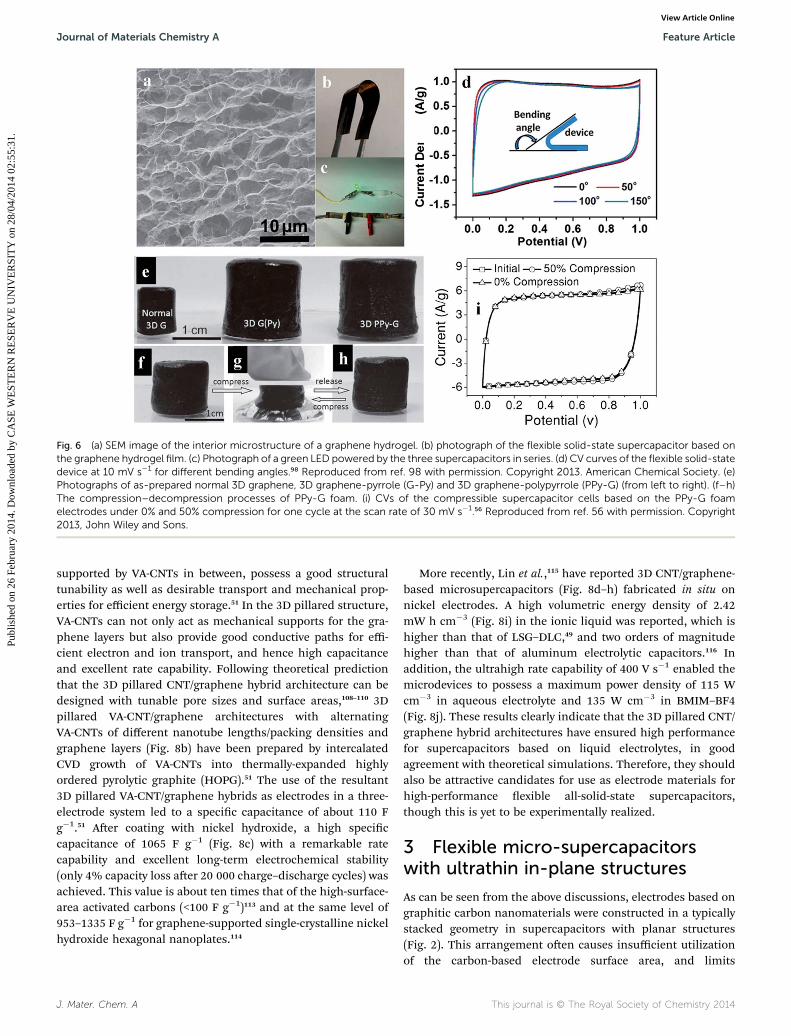
Fig. 6 (a) SEM image of the interior microstructure of a graphene hydrogel. (b) photograph of the flexible solid-state supercapacitor based onthe graphene hydrogel film. (c) Photograph of a green LED powered by the three supercapacitors in series. (d) CV curves of the flexible solid-statedevice at 10 mV s�1 for different bending angles.98 Reproduced from ref. 98 with permission. Copyright 2013. American Chemical Society. (e)Photographs of as-prepared normal 3D graphene, 3D graphene-pyrrole (G-Py) and 3D graphene-polypyrrole (PPy-G) (from left to right). (f–h)The compression–decompression processes of PPy-G foam. (i) CVs of the compressible supercapacitor cells based on the PPy-G foamelectrodes under 0% and 50% compression for one cycle at the scan rate of 30 mV s�1.56 Reproduced from ref. 56 with permission. Copyright2013, John Wiley and Sons.
Journal of Materials Chemistry A Feature Article
Publ
ishe
d on
26
Febr
uary
201
4. D
ownl
oade
d by
CA
SE W
EST
ER
N R
ESE
RV
E U
NIV
ER
SIT
Y o
n 28
/04/
2014
02:
55:3
1.
View Article Online
supported by VA-CNTs in between, possess a good structuraltunability as well as desirable transport and mechanical prop-erties for efficient energy storage.51 In the 3D pillared structure,VA-CNTs can not only act as mechanical supports for the gra-phene layers but also provide good conductive paths for effi-cient electron and ion transport, and hence high capacitanceand excellent rate capability. Following theoretical predictionthat the 3D pillared CNT/graphene hybrid architecture can bedesigned with tunable pore sizes and surface areas,108–110 3Dpillared VA-CNT/graphene architectures with alternatingVA-CNTs of different nanotube lengths/packing densities andgraphene layers (Fig. 8b) have been prepared by intercalatedCVD growth of VA-CNTs into thermally-expanded highlyordered pyrolytic graphite (HOPG).51 The use of the resultant3D pillared VA-CNT/graphene hybrids as electrodes in a three-electrode system led to a specic capacitance of about 110 Fg�1.51 Aer coating with nickel hydroxide, a high speciccapacitance of 1065 F g�1 (Fig. 8c) with a remarkable ratecapability and excellent long-term electrochemical stability(only 4% capacity loss aer 20 000 charge–discharge cycles) wasachieved. This value is about ten times that of the high-surface-area activated carbons (<100 F g�1)113 and at the same level of953–1335 F g�1 for graphene-supported single-crystalline nickelhydroxide hexagonal nanoplates.114
J. Mater. Chem. A
More recently, Lin et al.,115 have reported 3D CNT/graphene-based microsupercapacitors (Fig. 8d–h) fabricated in situ onnickel electrodes. A high volumetric energy density of 2.42mW h cm�3 (Fig. 8i) in the ionic liquid was reported, which ishigher than that of LSG–DLC,49 and two orders of magnitudehigher than that of aluminum electrolytic capacitors.116 Inaddition, the ultrahigh rate capability of 400 V s�1 enabled themicrodevices to possess a maximum power density of 115 Wcm�3 in aqueous electrolyte and 135 W cm�3 in BMIM–BF4(Fig. 8j). These results clearly indicate that the 3D pillared CNT/graphene hybrid architectures have ensured high performancefor supercapacitors based on liquid electrolytes, in goodagreement with theoretical simulations. Therefore, they shouldalso be attractive candidates for use as electrode materials forhigh-performance exible all-solid-state supercapacitors,though this is yet to be experimentally realized.
3 Flexible micro-supercapacitorswith ultrathin in-plane structures
As can be seen from the above discussions, electrodes based ongraphitic carbon nanomaterials were constructed in a typicallystacked geometry in supercapacitors with planar structures(Fig. 2). This arrangement oen causes insufficient utilizationof the carbon-based electrode surface area, and limits
This journal is © The Royal Society of Chemistry 2014
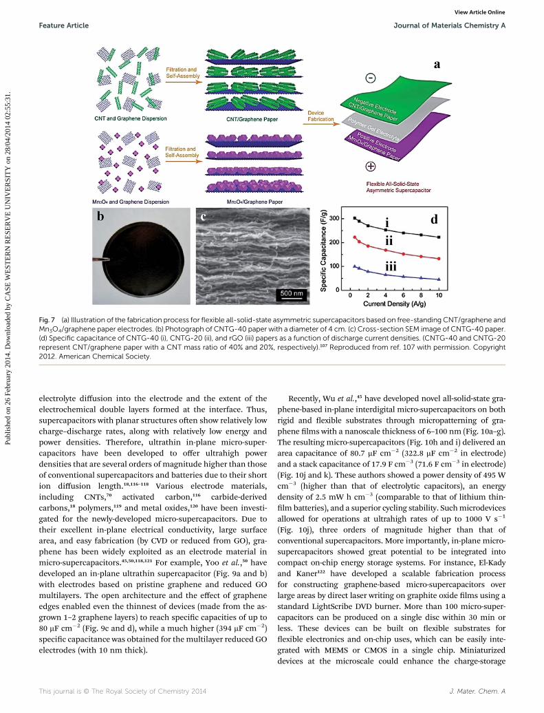
Fig. 7 (a) Illustration of the fabrication process for flexible all-solid-state asymmetric supercapacitors based on free-standing CNT/graphene andMn3O4/graphene paper electrodes. (b) Photograph of CNTG-40 paper with a diameter of 4 cm. (c) Cross-section SEM image of CNTG-40 paper.(d) Specific capacitance of CNTG-40 (i), CNTG-20 (ii), and rGO (iii) papers as a function of discharge current densities. (CNTG-40 and CNTG-20represent CNT/graphene paper with a CNT mass ratio of 40% and 20%, respectively).107 Reproduced from ref. 107 with permission. Copyright2012. American Chemical Society.
Feature Article Journal of Materials Chemistry A
Publ
ishe
d on
26
Febr
uary
201
4. D
ownl
oade
d by
CA
SE W
EST
ER
N R
ESE
RV
E U
NIV
ER
SIT
Y o
n 28
/04/
2014
02:
55:3
1.
View Article Online
electrolyte diffusion into the electrode and the extent of theelectrochemical double layers formed at the interface. Thus,supercapacitors with planar structures oen show relatively lowcharge–discharge rates, along with relatively low energy andpower densities. Therefore, ultrathin in-plane micro-super-capacitors have been developed to offer ultrahigh powerdensities that are several orders of magnitude higher than thoseof conventional supercapacitors and batteries due to their shortion diffusion length.18,116–118 Various electrode materials,including CNTs,70 activated carbon,116 carbide-derivedcarbons,18 polymers,119 and metal oxides,120 have been investi-gated for the newly-developed micro-supercapacitors. Due totheir excellent in-plane electrical conductivity, large surfacearea, and easy fabrication (by CVD or reduced from GO), gra-phene has been widely exploited as an electrode material inmicro-supercapacitors.45,50,118,121 For example, Yoo et al.,50 havedeveloped an in-plane ultrathin supercapacitor (Fig. 9a and b)with electrodes based on pristine graphene and reduced GOmultilayers. The open architecture and the effect of grapheneedges enabled even the thinnest of devices (made from the as-grown 1–2 graphene layers) to reach specic capacities of up to80 mF cm�2 (Fig. 9c and d), while a much higher (394 mF cm�2)specic capacitance was obtained for the multilayer reduced GOelectrodes (with 10 nm thick).
This journal is © The Royal Society of Chemistry 2014
Recently, Wu et al.,45 have developed novel all-solid-state gra-phene-based in-plane interdigital micro-supercapacitors on bothrigid and exible substrates through micropatterning of gra-phene lms with a nanoscale thickness of 6–100 nm (Fig. 10a–g).The resulting micro-supercapacitors (Fig. 10h and i) delivered anarea capacitance of 80.7 mF cm�2 (322.8 mF cm�2 in electrode)and a stack capacitance of 17.9 F cm�3 (71.6 F cm�3 in electrode)(Fig. 10j and k). These authors showed a power density of 495 Wcm�3 (higher than that of electrolytic capacitors), an energydensity of 2.5 mW h cm�3 (comparable to that of lithium thin-lm batteries), and a superior cycling stability. Suchmicrodevicesallowed for operations at ultrahigh rates of up to 1000 V s�1
(Fig. 10j), three orders of magnitude higher than that ofconventional supercapacitors. More importantly, in-plane micro-supercapacitors showed great potential to be integrated intocompact on-chip energy storage systems. For instance, El-Kadyand Kaner122 have developed a scalable fabrication processfor constructing graphene-based micro-supercapacitors overlarge areas by direct laser writing on graphite oxide lms using astandard LightScribe DVD burner. More than 100 micro-super-capacitors can be produced on a single disc within 30 min orless. These devices can be built on exible substrates forexible electronics and on-chip uses, which can be easily inte-grated with MEMS or CMOS in a single chip. Miniaturizeddevices at the microscale could enhance the charge-storage
J. Mater. Chem. A
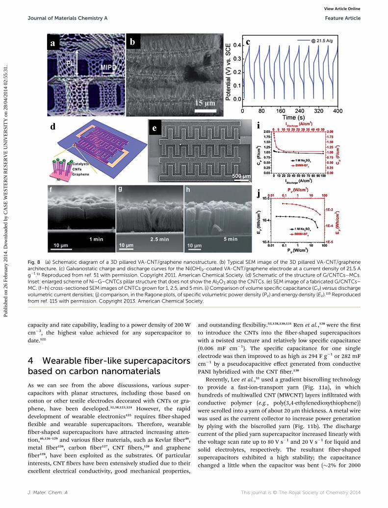
Fig. 8 (a) Schematic diagram of a 3D pillared VA-CNT/graphene nanostructure. (b) Typical SEM image of the 3D pillared VA-CNT/graphenearchitecture. (c) Galvanostatic charge and discharge curves for the Ni(OH)2-coated VA-CNT/graphene electrode at a current density of 21.5 Ag�1.51 Reproduced from ref. 51 with permission. Copyright 2011. American Chemical Society. (d) Schematic of the structure of G/CNTCs–MCs.Inset: enlarged scheme of Ni–G–CNTCs pillar structure that does not show the Al2O3 atop the CNTCs. (e) SEM image of a fabricated G/CNTCs–MC. (f–h) cross-sectioned SEM images of CNTCs grown for 1, 2.5, and 5min. (i) Comparison of volume specific capacitance (CV) versus dischargevolumetric current densities; (j) comparison, in the Ragone plots, of specific volumetric power density (PV) and energy density (EV).115 Reproducedfrom ref. 115 with permission. Copyright 2013. American Chemical Society.
Journal of Materials Chemistry A Feature Article
Publ
ishe
d on
26
Febr
uary
201
4. D
ownl
oade
d by
CA
SE W
EST
ER
N R
ESE
RV
E U
NIV
ER
SIT
Y o
n 28
/04/
2014
02:
55:3
1.
View Article Online
capacity and rate capability, leading to a power density of 200 Wcm�3, the highest value achieved for any supercapacitor todate.122
4 Wearable fiber-like supercapacitorsbased on carbon nanomaterials
As we can see from the above discussions, various super-capacitors with planar structures, including those based oncotton or other textile electrodes decorated with CNTs or gra-phene, have been developed.32,58,123,124 However, the rapiddevelopment of wearable electronics125 requires ber-shapedexible and wearable supercapacitors. Therefore, wearableber-shaped supercapacitors have attracted increasing atten-tion,46,126–129 and various ber materials, such as Kevlar ber46,metal ber126, carbon ber127, CNT bers,128 and grapheneber129, have been exploited as the substrates. Of particularinterests, CNT bers have been extensively studied due to theirexcellent electrical conductivity, good mechanical properties,
J. Mater. Chem. A
and outstanding exibility.52,128,130,131 Ren et al.,128 were the rstto introduce the CNTs into the ber-shaped supercapacitorswith a twisted structure and relatively low specic capacitance(0.006 mF cm�1). The specic capacitance for one singleelectrode was then improved to as high as 294 F g�1 or 282 mFcm�1 by a pseudocapacitive effect generated from conductivePANI hybridized with the CNT ber.130
Recently, Lee et al.,52 used a gradient biscrolling technologyto provide a fast-ion-transport yarn (Fig. 11a), in whichhundreds of multiwalled CNT (MWCNT) layers inltrated withconductive polymer (e.g., poly(3,4-ethylenedioxythiophene))were scrolled into a yarn of about 20 mm thickness. A metal wirewas used as the current collector to increase power generationby plying with the biscrolled yarn (Fig. 11b). The dischargecurrent of the plied yarn supercapacitor increased linearly withthe voltage scan rate up to 80 V s�1 and 20 V s�1 for liquid andsolid electrolytes, respectively. The resultant ber-shapedsupercapacitors exhibited a high stability; the capacitancechanged a little when the capacitor was bent (�2% for 2000
This journal is © The Royal Society of Chemistry 2014
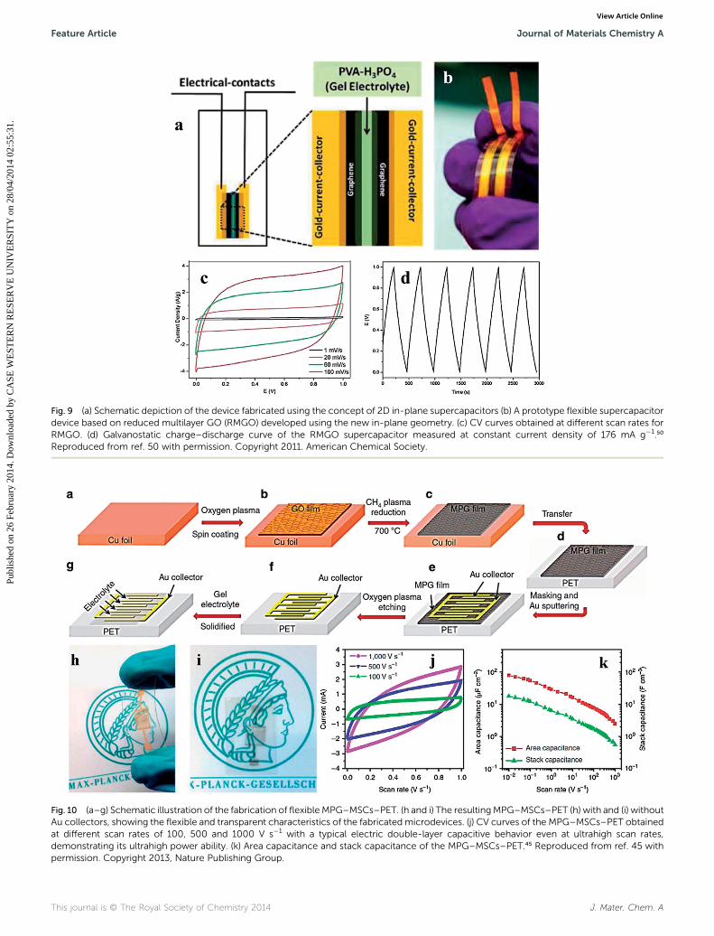
Fig. 9 (a) Schematic depiction of the device fabricated using the concept of 2D in-plane supercapacitors (b) A prototype flexible supercapacitordevice based on reduced multilayer GO (RMGO) developed using the new in-plane geometry. (c) CV curves obtained at different scan rates forRMGO. (d) Galvanostatic charge–discharge curve of the RMGO supercapacitor measured at constant current density of 176 mA g�1.50
Reproduced from ref. 50 with permission. Copyright 2011. American Chemical Society.
Fig. 10 (a–g) Schematic illustration of the fabrication of flexibleMPG–MSCs–PET. (h and i) The resultingMPG–MSCs–PET (h) with and (i) withoutAu collectors, showing the flexible and transparent characteristics of the fabricated microdevices. (j) CV curves of the MPG–MSCs–PET obtainedat different scan rates of 100, 500 and 1000 V s�1 with a typical electric double-layer capacitive behavior even at ultrahigh scan rates,demonstrating its ultrahigh power ability. (k) Area capacitance and stack capacitance of the MPG–MSCs–PET.45 Reproduced from ref. 45 withpermission. Copyright 2013, Nature Publishing Group.
This journal is © The Royal Society of Chemistry 2014 J. Mater. Chem. A
Feature Article Journal of Materials Chemistry A
Publ
ishe
d on
26
Febr
uary
201
4. D
ownl
oade
d by
CA
SE W
EST
ER
N R
ESE
RV
E U
NIV
ER
SIT
Y o
n 28
/04/
2014
02:
55:3
1.
View Article Online
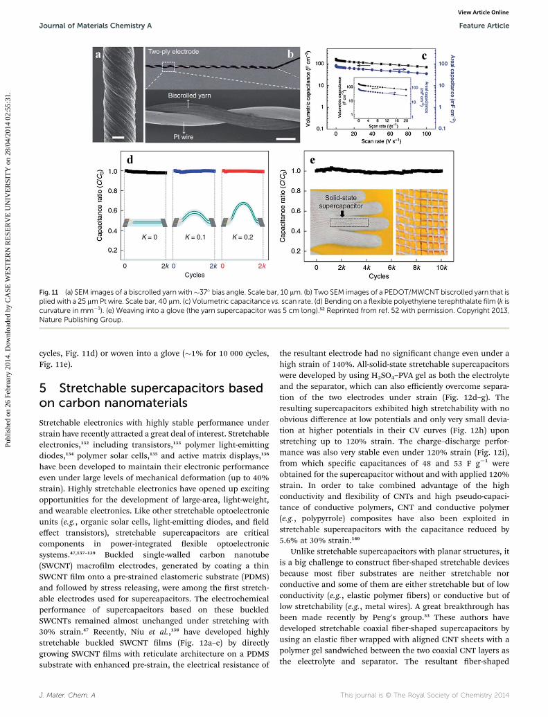
Fig. 11 (a) SEM images of a biscrolled yarn with�37� bias angle. Scale bar, 10 mm. (b) Two SEM images of a PEDOT/MWCNT biscrolled yarn that isplied with a 25 mmPt wire. Scale bar, 40 mm. (c) Volumetric capacitance vs. scan rate. (d) Bending on a flexible polyethylene terephthalate film (k iscurvature in mm�1). (e) Weaving into a glove (the yarn supercapacitor was 5 cm long).52 Reprinted from ref. 52 with permission. Copyright 2013,Nature Publishing Group.
Journal of Materials Chemistry A Feature Article
Publ
ishe
d on
26
Febr
uary
201
4. D
ownl
oade
d by
CA
SE W
EST
ER
N R
ESE
RV
E U
NIV
ER
SIT
Y o
n 28
/04/
2014
02:
55:3
1.
View Article Online
cycles, Fig. 11d) or woven into a glove (�1% for 10 000 cycles,Fig. 11e).
5 Stretchable supercapacitors basedon carbon nanomaterials
Stretchable electronics with highly stable performance understrain have recently attracted a great deal of interest. Stretchableelectronics,132 including transistors,133 polymer light-emittingdiodes,134 polymer solar cells,135 and active matrix displays,136
have been developed to maintain their electronic performanceeven under large levels of mechanical deformation (up to 40%strain). Highly stretchable electronics have opened up excitingopportunities for the development of large-area, light-weight,and wearable electronics. Like other stretchable optoelectronicunits (e.g., organic solar cells, light-emitting diodes, and eldeffect transistors), stretchable supercapacitors are criticalcomponents in power-integrated exible optoelectronicsystems.47,137–139 Buckled single-walled carbon nanotube(SWCNT) macrolm electrodes, generated by coating a thinSWCNT lm onto a pre-strained elastomeric substrate (PDMS)and followed by stress releasing, were among the rst stretch-able electrodes used for supercapacitors. The electrochemicalperformance of supercapacitors based on these buckledSWCNTs remained almost unchanged under stretching with30% strain.47 Recently, Niu et al.,138 have developed highlystretchable buckled SWCNT lms (Fig. 12a–c) by directlygrowing SWCNT lms with reticulate architecture on a PDMSsubstrate with enhanced pre-strain, the electrical resistance of
J. Mater. Chem. A
the resultant electrode had no signicant change even under ahigh strain of 140%. All-solid-state stretchable supercapacitorswere developed by using H2SO4–PVA gel as both the electrolyteand the separator, which can also efficiently overcome separa-tion of the two electrodes under strain (Fig. 12d–g). Theresulting supercapacitors exhibited high stretchability with noobvious difference at low potentials and only very small devia-tion at higher potentials in their CV curves (Fig. 12h) uponstretching up to 120% strain. The charge–discharge perfor-mance was also very stable even under 120% strain (Fig. 12i),from which specic capacitances of 48 and 53 F g�1 wereobtained for the supercapacitor without and with applied 120%strain. In order to take combined advantage of the highconductivity and exibility of CNTs and high pseudo-capaci-tance of conductive polymers, CNT and conductive polymer(e.g., polypyrrole) composites have also been exploited instretchable supercapacitors with the capacitance reduced by5.6% at 30% strain.140
Unlike stretchable supercapacitors with planar structures, itis a big challenge to construct ber-shaped stretchable devicesbecause most ber substrates are neither stretchable norconductive and some of them are either stretchable but of lowconductivity (e.g., elastic polymer bers) or conductive but oflow stretchability (e.g., metal wires). A great breakthrough hasbeen made recently by Peng's group.53 These authors havedeveloped stretchable coaxial ber-shaped supercapacitors byusing an elastic ber wrapped with aligned CNT sheets with apolymer gel sandwiched between the two coaxial CNT layers asthe electrolyte and separator. The resultant ber-shaped
This journal is © The Royal Society of Chemistry 2014
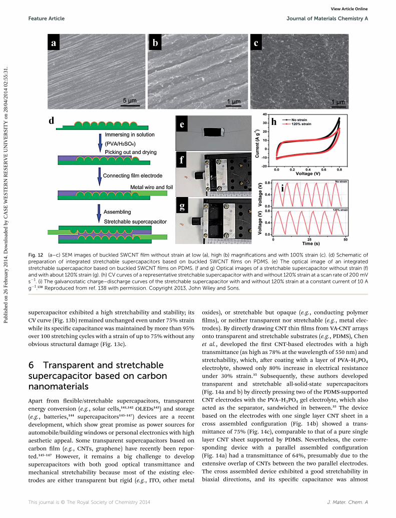
Fig. 12 (a–c) SEM images of buckled SWCNT film without strain at low (a), high (b) magnifications and with 100% strain (c). (d) Schematic ofpreparation of integrated stretchable supercapacitors based on buckled SWCNT films on PDMS. (e) The optical image of an integratedstretchable supercapacitor based on buckled SWCNT films on PDMS. (f and g) Optical images of a stretchable supercapacitor without strain (f)and with about 120% strain (g). (h) CV curves of a representative stretchable supercapacitor with and without 120% strain at a scan rate of 200mVs�1. (i) The galvanostatic charge–discharge curves of the stretchable supercapacitor with and without 120% strain at a constant current of 10 Ag�1.138 Reproduced from ref. 138 with permission. Copyright 2013, John Wiley and Sons.
Feature Article Journal of Materials Chemistry A
Publ
ishe
d on
26
Febr
uary
201
4. D
ownl
oade
d by
CA
SE W
EST
ER
N R
ESE
RV
E U
NIV
ER
SIT
Y o
n 28
/04/
2014
02:
55:3
1.
View Article Online
supercapacitor exhibited a high stretchability and stability; itsCV curve (Fig. 13b) remained unchanged even under 75% strainwhile its specic capacitance wasmaintained by more than 95%over 100 stretching cycles with a strain of up to 75% without anyobvious structural damage (Fig. 13c).
6 Transparent and stretchablesupercapacitor based on carbonnanomaterials
Apart from exible/stretchable supercapacitors, transparentenergy conversion (e.g., solar cells,141,142 OLEDs143) and storage(e.g., batteries,144 supercapacitors145–147) devices are a recentdevelopment, which show great promise as power sources forautomobile/building windows or personal electronics with highaesthetic appeal. Some transparent supercapacitors based oncarbon lm (e.g., CNTs, graphene) have recently been repor-ted.145–147 However, it remains a big challenge to developsupercapacitors with both good optical transmittance andmechanical stretchability because most of the existing elec-trodes are either transparent but rigid (e.g., ITO, other metal
This journal is © The Royal Society of Chemistry 2014
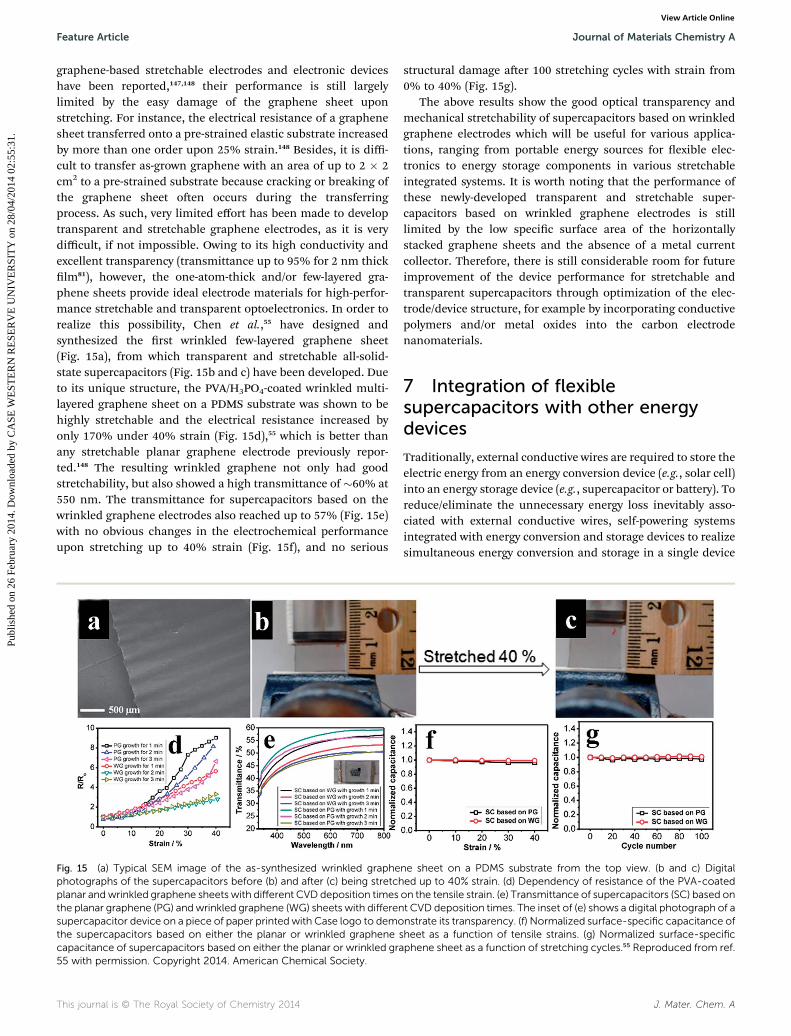
oxides), or stretchable but opaque (e.g., conducting polymerlms), or neither transparent nor stretchable (e.g., metal elec-trodes). By directly drawing CNT thin lms from VA-CNT arraysonto transparent and stretchable substrates (e.g., PDMS), Chenet al., developed the rst CNT-based electrodes with a hightransmittance (as high as 78% at the wavelength of 550 nm) andstretchability, which, aer coating with a layer of PVA–H3PO4
electrolyte, showed only 80% increase in electrical resistanceunder 30% strain.35 Subsequently, these authors developedtransparent and stretchable all-solid-state supercapacitors(Fig. 14a and b) by directly pressing two of the PDMS-supportedCNT electrodes with the PVA–H3PO4 gel electrolyte, which alsoacted as the separator, sandwiched in between.35 The devicebased on the electrodes with one single layer CNT sheet in across assembled conguration (Fig. 14b) showed a trans-mittance of 75% (Fig. 14c), comparable to that of a pure singlelayer CNT sheet supported by PDMS. Nevertheless, the corre-sponding device with a parallel assembled conguration(Fig. 14a) had a transmittance of 64%, presumably due to theextensive overlap of CNTs between the two parallel electrodes.The cross assembled device exhibited a good stretchability inbiaxial directions, and its specic capacitance was almost
J. Mater. Chem. A
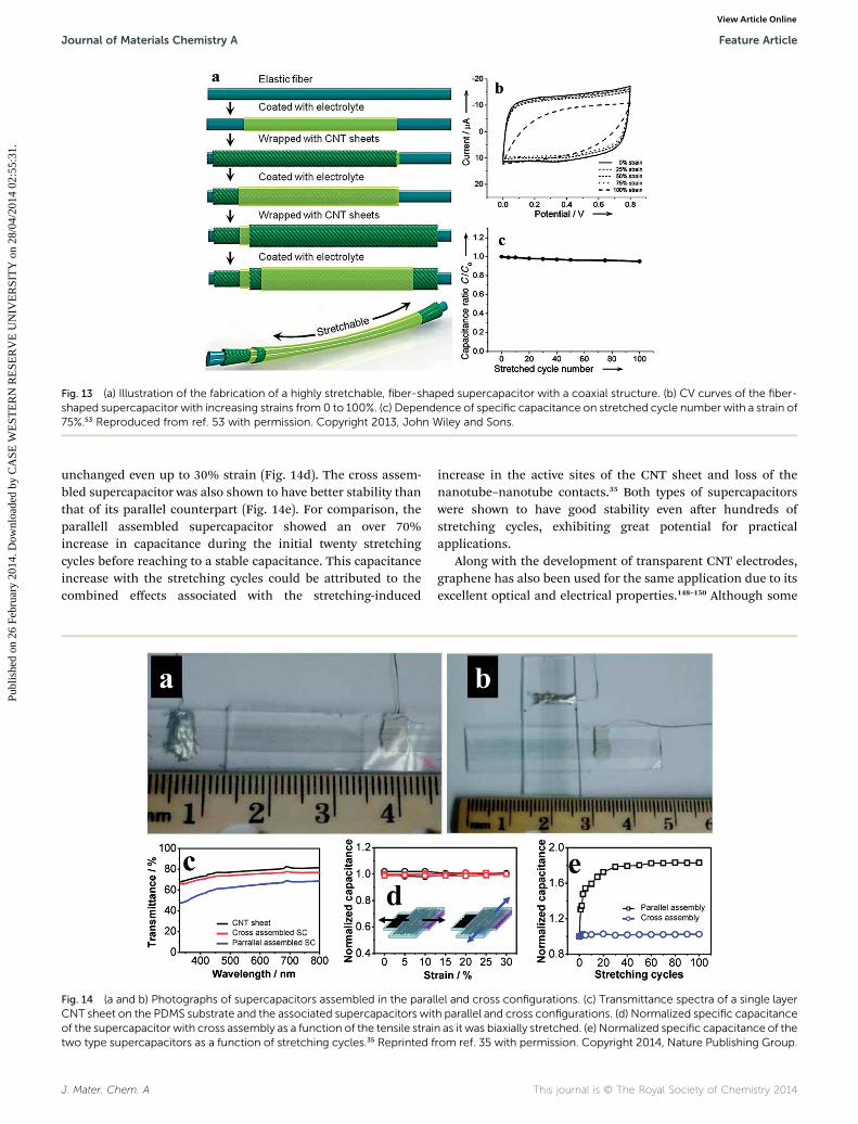
Fig. 13 (a) Illustration of the fabrication of a highly stretchable, fiber-shaped supercapacitor with a coaxial structure. (b) CV curves of the fiber-shaped supercapacitor with increasing strains from 0 to 100%. (c) Dependence of specific capacitance on stretched cycle number with a strain of75%.53 Reproduced from ref. 53 with permission. Copyright 2013, John Wiley and Sons.
Journal of Materials Chemistry A Feature Article
Publ
ishe
d on
26
Febr
uary
201
4. D
ownl
oade
d by
CA
SE W
EST
ER
N R
ESE
RV
E U
NIV
ER
SIT
Y o
n 28
/04/
2014
02:
55:3
1.
View Article Online
unchanged even up to 30% strain (Fig. 14d). The cross assem-bled supercapacitor was also shown to have better stability thanthat of its parallel counterpart (Fig. 14e). For comparison, theparallell assembled supercapacitor showed an over 70%increase in capacitance during the initial twenty stretchingcycles before reaching to a stable capacitance. This capacitanceincrease with the stretching cycles could be attributed to thecombined effects associated with the stretching-induced
Fig. 14 (a and b) Photographs of supercapacitors assembled in the paralCNT sheet on the PDMS substrate and the associated supercapacitors witof the supercapacitor with cross assembly as a function of the tensile straitwo type supercapacitors as a function of stretching cycles.35 Reprinted f
J. Mater. Chem. A
increase in the active sites of the CNT sheet and loss of thenanotube–nanotube contacts.35 Both types of supercapacitorswere shown to have good stability even aer hundreds ofstretching cycles, exhibiting great potential for practicalapplications.
Along with the development of transparent CNT electrodes,graphene has also been used for the same application due to itsexcellent optical and electrical properties.148–150 Although some
lel and cross configurations. (c) Transmittance spectra of a single layerh parallel and cross configurations. (d) Normalized specific capacitancen as it was biaxially stretched. (e) Normalized specific capacitance of therom ref. 35 with permission. Copyright 2014, Nature Publishing Group.
This journal is © The Royal Society of Chemistry 2014
Feature Article Journal of Materials Chemistry A
Publ
ishe
d on
26
Febr
uary
201
4. D
ownl
oade
d by
CA
SE W
EST
ER
N R
ESE
RV
E U
NIV
ER
SIT
Y o
n 28
/04/
2014
02:
55:3
1.
View Article Online
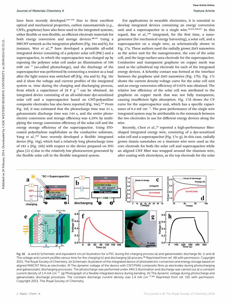
graphene-based stretchable electrodes and electronic deviceshave been reported,147,148 their performance is still largelylimited by the easy damage of the graphene sheet uponstretching. For instance, the electrical resistance of a graphenesheet transferred onto a pre-strained elastic substrate increasedby more than one order upon 25% strain.148 Besides, it is diffi-cult to transfer as-grown graphene with an area of up to 2 � 2cm2 to a pre-strained substrate because cracking or breaking ofthe graphene sheet oen occurs during the transferringprocess. As such, very limited effort has been made to developtransparent and stretchable graphene electrodes, as it is verydifficult, if not impossible. Owing to its high conductivity andexcellent transparency (transmittance up to 95% for 2 nm thicklm81), however, the one-atom-thick and/or few-layered gra-phene sheets provide ideal electrode materials for high-perfor-mance stretchable and transparent optoelectronics. In order torealize this possibility, Chen et al.,55 have designed andsynthesized the rst wrinkled few-layered graphene sheet(Fig. 15a), from which transparent and stretchable all-solid-state supercapacitors (Fig. 15b and c) have been developed. Dueto its unique structure, the PVA/H3PO4-coated wrinkled multi-layered graphene sheet on a PDMS substrate was shown to behighly stretchable and the electrical resistance increased byonly 170% under 40% strain (Fig. 15d),55 which is better thanany stretchable planar graphene electrode previously repor-ted.148 The resulting wrinkled graphene not only had goodstretchability, but also showed a high transmittance of �60% at550 nm. The transmittance for supercapacitors based on thewrinkled graphene electrodes also reached up to 57% (Fig. 15e)with no obvious changes in the electrochemical performanceupon stretching up to 40% strain (Fig. 15f), and no serious
Fig. 15 (a) Typical SEM image of the as-synthesized wrinkled graphephotographs of the supercapacitors before (b) and after (c) being stretchplanar andwrinkled graphene sheets with different CVD deposition timesthe planar graphene (PG) andwrinkled graphene (WG) sheets with differensupercapacitor device on a piece of paper printedwith Case logo to demothe supercapacitors based on either the planar or wrinkled graphene scapacitance of supercapacitors based on either the planar or wrinkled gra55 with permission. Copyright 2014. American Chemical Society.
This journal is © The Royal Society of Chemistry 2014
structural damage aer 100 stretching cycles with strain from0% to 40% (Fig. 15g).
The above results show the good optical transparency andmechanical stretchability of supercapacitors based on wrinkledgraphene electrodes which will be useful for various applica-tions, ranging from portable energy sources for exible elec-tronics to energy storage components in various stretchableintegrated systems. It is worth noting that the performance ofthese newly-developed transparent and stretchable super-capacitors based on wrinkled graphene electrodes is stilllimited by the low specic surface area of the horizontallystacked graphene sheets and the absence of a metal currentcollector. Therefore, there is still considerable room for futureimprovement of the device performance for stretchable andtransparent supercapacitors through optimization of the elec-trode/device structure, for example by incorporating conductivepolymers and/or metal oxides into the carbon electrodenanomaterials.
7 Integration of flexiblesupercapacitors with other energydevices
Traditionally, external conductive wires are required to store theelectric energy from an energy conversion device (e.g., solar cell)into an energy storage device (e.g., supercapacitor or battery). Toreduce/eliminate the unnecessary energy loss inevitably asso-ciated with external conductive wires, self-powering systemsintegrated with energy conversion and storage devices to realizesimultaneous energy conversion and storage in a single device
ne sheet on a PDMS substrate from the top view. (b and c) Digitaled up to 40% strain. (d) Dependency of resistance of the PVA-coatedon the tensile strain. (e) Transmittance of supercapacitors (SC) based ont CVD deposition times. The inset of (e) shows a digital photograph of anstrate its transparency. (f) Normalized surface-specific capacitance ofheet as a function of tensile strains. (g) Normalized surface-specificphene sheet as a function of stretching cycles.55 Reproduced from ref.
J. Mater. Chem. A
Journal of Materials Chemistry A Feature Article
Publ
ishe
d on
26
Febr
uary
201
4. D
ownl
oade
d by
CA
SE W
EST
ER
N R
ESE
RV
E U
NIV
ER
SIT
Y o
n 28
/04/
2014
02:
55:3
1.
View Article Online
have been recently developed.151–154 Due to their excellentoptical and mechanical properties, carbon nanomaterials (e.g.,CNTs, graphene) have also been used in the integrated systems,either exible or non-exible, as efficient electrode materials forboth energy conversion and storage devices.48,155 Using aSWCNT network as the integration platform (Fig. 16a and b), forinstance, Wee et al.,48 have developed a printable all-solidintegrated device consisting of a polymer solar cell (PSC) and asupercapacitor, in which the supercapacitor was charged up byexposing the polymer solar cell under an illumination of 100mW cm�2 (so-called photocharge), and the discharge of thesupercapacitor was performed by connecting a resistor as a loadaer the light source was switched off (Fig. 16a and b). Fig. 16cand d show the voltage and current proles of the integratedsystem vs. time during the charging and discharging process,from which a capacitance of 28 F g�1 can be obtained. Anintegrated device consisting of an all-solid-state dye-sensitizedsolar cell and a supercapacitor based on CNT/polyanilinecomposite electrodes has also been reported (Fig. 16e).155 FromFig. 16f, it was estimated that the photocharge time was 33 s,galvanostatic discharge time was 144 s, and the entire photo-electric conversion and storage efficiency was 4.29% by multi-plying the energy conversion efficiency of the solar cell and theenergy storage efficiency of the supercapacitor. Using ITO-coated polyethylene naphthalate as the conductive substrate,Yang et al.,155 have recently developed a exible integrateddevice (Fig. 16g), which had a relatively long photocharge timeof 183 s (Fig. 16h) with respect to the device prepared on ITOglass (33 s) due to the relatively low photocurrent generated bythe exible solar cell in the exible integrated system.
Fig. 16 (a and b) Schematic and equivalent circuit illustration for a PSC dThe voltage and current profiles versus time for the charging (c) and disch2011, The Royal Society of Chemistry. (e) Schematic illustration of the intealigned MWCNT films as electrodes. (f) The dynamic voltage of the devicand galvanostatic discharging processes. The photocharge was performecurrent density of 1.4 mA cm�2. (g) Photograph of a flexible integrated degalvanostatic discharge processes. The constant discharge current deCopyright 2013, The Royal Society of Chemistry.
J. Mater. Chem. A
For applications in wearable electronics, it is essential todevelop integrated devices containing an energy conversionunit and a supercapacitor in a single wire.54,151,156,157 In thisregard, Bae et al.,156 integrated, for the rst time, a nano-generator (for mechanical energy harvesting), a solar cell, and asupercapacitor on a single wire, as schematically shown inFig. 17a. These authors used the radially grown ZnO nanowiresas the active unit for the nanogenerator, the core of the solarcell, and the large-surface-area electrode for the supercapacitor.Conductive and transparent graphene on copper mesh wasused as the cylindrical top electrode for each of the integratedenergy devices. A Schottky contact was formed at the interfacebetween the graphene and ZnO nanowires (Fig. 17b). Fig. 17cshows the current density–voltage curve for the solar cell unitand an energy conversion efficiency of 0.02% was obtained. Therelative low efficiency of the solar cell was attributed to thegraphene on copper mesh that was not fully transparent,causing insufficient light absorption. Fig. 17d shows the CVcurve for the supercapacitor unit, which has a specic capaci-tance of 0.4 mF cm�2. The poor performance of the single wireintegrated systemmay be attributable to the mismatch betweenthe two electrodes in use for different energy devices along thewire.
Recently, Chen et al.,54 reported a high-performance ber-shaped integrated energy wire, consisting of a dye-sensitizedsolar cell and a supercapacitor (Fig. 17e–g). In this case, radiallygrown titania nanotubes on a titanium wire were used as thecore electrode for both the solar cell and supercapacitor whilean aligned CNT ber was wrapped around the titanium wire,aer coating with electrolytes, as the top electrode for the solar
uring the charging process (a) and galvanostatic discharge (b). (c and d)arging (d) process.48 Reprinted from ref. 48 with permission. Copyrightgrated device of photoelectric conversion and energy storage based one with CNT/PANI composite films as electrodes during photochargingd under AM1.5 illumination and discharge was carried out at a constantvice during bending. (h) The dynamic voltage during photocharge andnsity was 1.4 mA cm�2.155 Reprinted from ref. 155 with permission.
This journal is © The Royal Society of Chemistry 2014
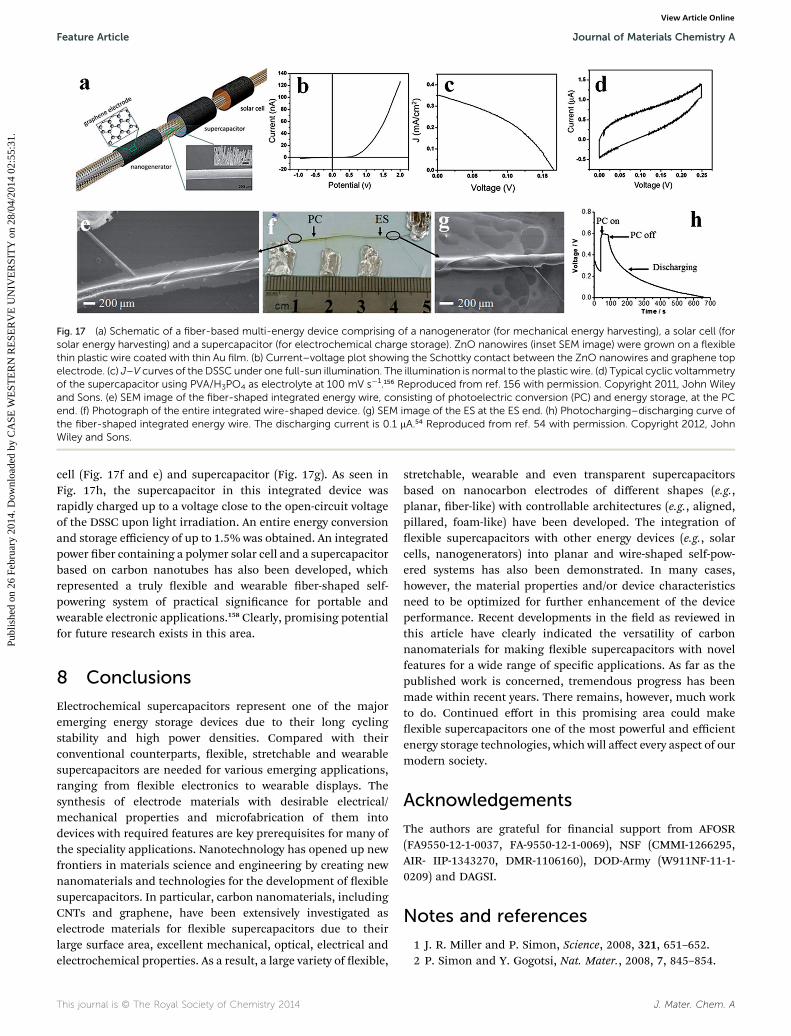
Fig. 17 (a) Schematic of a fiber-based multi-energy device comprising of a nanogenerator (for mechanical energy harvesting), a solar cell (forsolar energy harvesting) and a supercapacitor (for electrochemical charge storage). ZnO nanowires (inset SEM image) were grown on a flexiblethin plastic wire coated with thin Au film. (b) Current–voltage plot showing the Schottky contact between the ZnO nanowires and graphene topelectrode. (c) J–V curves of the DSSC under one full-sun illumination. The illumination is normal to the plastic wire. (d) Typical cyclic voltammetryof the supercapacitor using PVA/H3PO4 as electrolyte at 100 mV s�1.156 Reproduced from ref. 156 with permission. Copyright 2011, John Wileyand Sons. (e) SEM image of the fiber-shaped integrated energy wire, consisting of photoelectric conversion (PC) and energy storage, at the PCend. (f) Photograph of the entire integrated wire-shaped device. (g) SEM image of the ES at the ES end. (h) Photocharging–discharging curve ofthe fiber-shaped integrated energy wire. The discharging current is 0.1 mA.54 Reproduced from ref. 54 with permission. Copyright 2012, JohnWiley and Sons.
Feature Article Journal of Materials Chemistry A
Publ
ishe
d on
26
Febr
uary
201
4. D
ownl
oade
d by
CA
SE W
EST
ER
N R
ESE
RV
E U
NIV
ER
SIT
Y o
n 28
/04/
2014
02:
55:3
1.
View Article Online
cell (Fig. 17f and e) and supercapacitor (Fig. 17g). As seen inFig. 17h, the supercapacitor in this integrated device wasrapidly charged up to a voltage close to the open-circuit voltageof the DSSC upon light irradiation. An entire energy conversionand storage efficiency of up to 1.5% was obtained. An integratedpower ber containing a polymer solar cell and a supercapacitorbased on carbon nanotubes has also been developed, whichrepresented a truly exible and wearable ber-shaped self-powering system of practical signicance for portable andwearable electronic applications.158 Clearly, promising potentialfor future research exists in this area.
8 Conclusions
Electrochemical supercapacitors represent one of the majoremerging energy storage devices due to their long cyclingstability and high power densities. Compared with theirconventional counterparts, exible, stretchable and wearablesupercapacitors are needed for various emerging applications,ranging from exible electronics to wearable displays. Thesynthesis of electrode materials with desirable electrical/mechanical properties and microfabrication of them intodevices with required features are key prerequisites for many ofthe speciality applications. Nanotechnology has opened up newfrontiers in materials science and engineering by creating newnanomaterials and technologies for the development of exiblesupercapacitors. In particular, carbon nanomaterials, includingCNTs and graphene, have been extensively investigated aselectrode materials for exible supercapacitors due to theirlarge surface area, excellent mechanical, optical, electrical andelectrochemical properties. As a result, a large variety of exible,
This journal is © The Royal Society of Chemistry 2014
stretchable, wearable and even transparent supercapacitorsbased on nanocarbon electrodes of different shapes (e.g.,planar, ber-like) with controllable architectures (e.g., aligned,pillared, foam-like) have been developed. The integration ofexible supercapacitors with other energy devices (e.g., solarcells, nanogenerators) into planar and wire-shaped self-pow-ered systems has also been demonstrated. In many cases,however, the material properties and/or device characteristicsneed to be optimized for further enhancement of the deviceperformance. Recent developments in the eld as reviewed inthis article have clearly indicated the versatility of carbonnanomaterials for making exible supercapacitors with novelfeatures for a wide range of specic applications. As far as thepublished work is concerned, tremendous progress has beenmade within recent years. There remains, however, much workto do. Continued effort in this promising area could makeexible supercapacitors one of the most powerful and efficientenergy storage technologies, which will affect every aspect of ourmodern society.
Acknowledgements
The authors are grateful for nancial support from AFOSR(FA9550-12-1-0037, FA-9550-12-1-0069), NSF (CMMI-1266295,AIR- IIP-1343270, DMR-1106160), DOD-Army (W911NF-11-1-0209) and DAGSI.
Notes and references
1 J. R. Miller and P. Simon, Science, 2008, 321, 651–652.2 P. Simon and Y. Gogotsi, Nat. Mater., 2008, 7, 845–854.
J. Mater. Chem. A
Journal of Materials Chemistry A Feature Article
Publ
ishe
d on
26
Febr
uary
201
4. D
ownl
oade
d by
CA
SE W
EST
ER
N R
ESE
RV
E U
NIV
ER
SIT
Y o
n 28
/04/
2014
02:
55:3
1.
View Article Online
3 M. Winter and R. J. Brodd, Chem. Rev., 2004, 104, 4245–4270.
4 J. Zhang and X. Zhao, ChemSusChem, 2012, 5, 818–841.5 T. Chen and L. Dai, Mater. Today, 2013, 16, 272–280.6 J. Gamby, P. Taberna, P. Simon, J. Fauvarque andM. Chesneau, J. Power Sources, 2001, 101, 109–116.
7 E. Frackowiak and F. Beguin, Carbon, 2001, 39, 937–950.8 L.-F. Chen, Z.-H. Huang, H.-W. Liang, W.-T. Yao, Z.-Y. Yuand S.-H. Yu, Energy Environ. Sci., 2013, 6, 3331–3338.
9 X. Tao, X. Zhang, L. Zhang, J. Cheng, F. Liu, J. Luo, Z. Luoand H. J. Geise, Carbon, 2006, 44, 1425–1428.
10 J. Huang, B. G. Sumpter and V. Meunier, Angew. Chem., Int.Ed., 2008, 47, 520–524.
11 D.-W. Wang, F. Li, Z.-G. Chen, G. Q. Lu and H.-M. Cheng,Chem. Mater., 2008, 20, 7195–7200.
12 D. N. Futaba, K. Hata, T. Yamada, T. Hiraoka, Y. Hayamizu,Y. Kakudate, O. Tanaike, H. Hatori, M. Yumura andS. Iijima, Nat. Mater., 2006, 5, 987–994.
13 L. Dai, D. W. Chang, J. B. Baek and W. Lu, Small, 2012, 8,1130–1166.
14 Y. Wang, Z. Shi, Y. Huang, Y. Ma, C. Wang, M. Chen andY. Chen, J. Phys. Chem. C, 2009, 113, 13103–13107.
15 L. L. Zhang, R. Zhou and X. Zhao, J. Mater. Chem., 2010, 20,5983–5992.
16 J. Hou, Y. Shao, M. W. Ellis, R. B. Moore and B. Yi, Phys.Chem. Chem. Phys., 2011, 13, 15384–15402.
17 J. Chmiola, G. Yushin, Y. Gogotsi, C. Portet, P. Simon andP.-L. Taberna, Science, 2006, 313, 1760–1763.
18 J. Chmiola, C. Largeot, P.-L. Taberna, P. Simon andY. Gogotsi, Science, 2010, 328, 480–483.
19 Q. Wu, Y. Xu, Z. Yao, A. Liu and G. Shi, ACS Nano, 2010, 4,1963–1970.
20 H.-P. Cong, X.-C. Ren, P. Wang and S.-H. Yu, Energy Environ.Sci., 2013, 6, 1185–1191.
21 K. Jurewicz, S. Delpeux, V. Bertagna, F. Beguin andE. Frackowiak, Chem. Phys. Lett., 2001, 347, 36–40.
22 L. Yuan, B. Yao, B. Hu, K. Huo, W. Chen and J. Zhou, EnergyEnviron. Sci., 2013, 6, 470–476.
23 F. Alvi, M. K. Ram, P. A. Basnayaka, E. Stefanakos,Y. Goswami and A. Kumar, Electrochim. Acta, 2011, 56,9406–9412.
24 W. Wei, X. Cui, W. Chen and D. G. Ivey, Chem. Soc. Rev.,2011, 40, 1697–1721.
25 S. Chen, J. Zhu, X. Wu, Q. Han and X. Wang, ACS Nano,2010, 4, 2822–2830.
26 C. Yuan, X. Zhang, L. Su, B. Gao and L. Shen, J. Mater.Chem., 2009, 19, 5772–5777.
27 C.-C. Hu, K.-H. Chang, M.-C. Lin and Y.-T. Wu, Nano Lett.,2006, 6, 2690–2695.
28 Z. Chen, V. Augustyn, J. Wen, Y. Zhang, M. Shen, B. Dunnand Y. Lu, Adv. Mater., 2011, 23, 791–795.
29 A. Pandolfo and A. Hollenkamp, J. Power Sources, 2006, 157,11–27.
30 R. Kotz and M. Carlen, Electrochim. Acta, 2000, 45, 2483–2498.
31 M. D. Stoller and R. S. Ruoff, Energy Environ. Sci., 2010, 3,1294–1301.
J. Mater. Chem. A
32 L. Hu and Y. Cui, Energy Environ. Sci., 2012, 5, 6423–6435.33 S. Park, M. Vosguerichian and Z. Bao, Nanoscale, 2013, 5,
1727–1752.34 Y. He, W. Chen, C. Gao, J. Zhou, X. Li and E. Xie, Nanoscale,
2013, 5, 8799–8820.35 T. Chen, H. Peng, M. Durstock and L. Dai, Sci. Rep., 2014, 4,
3612–3618.36 B. G. Choi, J. Hong, W. H. Hong, P. T. Hammond and
H. Park, ACS Nano, 2011, 5, 7205–7213.37 K. Novoselov, V. Fal, L. Colombo, P. Gellert, M. Schwab and
K. Kim, Nature, 2012, 490, 192–200.38 S. Bose, T. Kuila, A. K. Mishra, R. Rajasekar, N. H. Kim and
J. H. Lee, J. Mater. Chem., 2012, 22, 767–784.39 H. Jiang, P. S. Lee and C. Li, Energy Environ. Sci., 2013, 6, 41–
53.40 Y. Cheng and J. Liu, Mater. Res. Lett., 2013, 1, 175–192.41 C. Xu, B. Xu, Y. Gu, Z. Xiong, J. Sun and X. Zhao, Energy
Environ. Sci., 2013, 6, 1388–1414.42 L. L. Zhang, Y. Gu and X. S. Zhao, J. Mater. Chem. A, 2013, 1,
9395–9408.43 G. A. Snook, P. Kao and A. S. Best, J. Power Sources, 2011,
196, 1–12.44 K. Wang, H. Wu, Y. Meng and Z. Wei, Small, 2014, 10, 14–
31.45 Z. S. Wu, K. Parvez, X. Feng and K. Mullen, Nat. Commun.,
2013, 4, 2487–2494.46 J. Bae, M. K. Song, Y. J. Park, J. M. Kim, M. Liu and
Z. L. Wang, Angew. Chem., Int. Ed., 2011, 50, 1683–1687.47 C. Yu, C. Masarapu, J. Rong, B. Wei and H. Jiang, Adv.
Mater., 2009, 21, 4793–4797.48 G. Wee, T. Salim, Y. M. Lam, S. G. Mhaisalkar and
M. Srinivasan, Energy Environ. Sci., 2011, 4, 413–416.49 M. F. El-Kady, V. Strong, S. Dubin and R. B. Kaner, Science,
2012, 335, 1326–1330.50 J. J. Yoo, K. Balakrishnan, J. Huang, V. Meunier,
B. G. Sumpter, A. Srivastava, M. Conway, A. L. MohanaReddy, J. Yu and R. Vajtai, Nano Lett., 2011, 11, 1423–1427.
51 F. Du, D. Yu, L. Dai, S. Ganguli, V. Varshney and A. Roy,Chem. Mater., 2011, 23, 4810–4816.
52 J. A. Lee, M. K. Shin, S. H. Kim, H. U. Cho, G. M. Spinks,G. G. Wallace, M. D. Lima, X. Lepro, M. E. Kozlov,R. H. Baughman and S. J. Kim, Nat Commun., 2013, 4,1970–1977.
53 Z. Yang, J. Deng, X. Chen, J. Ren and H. Peng, Angew. Chem.,Int. Ed., 2013, 52, 13453–13457.
54 T. Chen, L. Qiu, Z. Yang, Z. Cai, J. Ren, H. Li, H. Lin, X. Sunand H. Peng, Angew. Chem., Int. Ed., 2012, 51, 11977–11980.
55 T. Chen, Y. Xue, A. K. Roy and L. Dai, ACS Nano, 2014, 8,1039–1046.
56 Y. Zhao, J. Liu, Y. Hu, H. Cheng, C. Hu, C. Jiang, L. Jiang,A. Cao and L. Qu, Adv. Mater., 2013, 25, 591–595.
57 M. Kaempgen, C. K. Chan, J. Ma, Y. Cui and G. Gruner,Nano Lett., 2009, 9, 1872–1876.
58 L. Hu, M. Pasta, F. L. Mantia, L. Cui, S. Jeong,H. D. Deshazer, J. W. Choi, S. M. Han and Y. Cui, NanoLett., 2010, 10, 708–714.
This journal is © The Royal Society of Chemistry 2014
Feature Article Journal of Materials Chemistry A
Publ
ishe
d on
26
Febr
uary
201
4. D
ownl
oade
d by
CA
SE W
EST
ER
N R
ESE
RV
E U
NIV
ER
SIT
Y o
n 28
/04/
2014
02:
55:3
1.
View Article Online
59 Y. J. Kang, H. Chung, C.-H. Han and W. Kim,Nanotechnology, 2012, 23, 065401.
60 Y. J. Kang, S.-J. Chun, S.-S. Lee, B.-Y. Kim, J. H. Kim,H. Chung, S.-Y. Lee and W. Kim, ACS Nano, 2012, 6,6400–6406.
61 V. L. Pushparaj, M. M. Shaijumon, A. Kumar, S. Murugesan,L. Ci, R. Vajtai, R. J. Linhardt, O. Nalamasu andP. M. Ajayan, Proc. Natl. Acad. Sci. U. S. A., 2007, 104, 13574–13577.
62 C. Huang and P. S. Grant, Sci. Rep., 2013, 3, 2393–2401.63 L. Hu, W. Chen, X. Xie, N. Liu, Y. Yang, H. Wu, Y. Yao,
M. Pasta, H. N. Alshareef and Y. Cui, ACS Nano, 2011, 5,8904–8913.
64 G. Yu, X. Xie, L. Pan, Z. Bao and Y. Cui, Nano Energy, 2013, 2,213–234.
65 L. Nyholm, G. Nystrom, A. Mihranyan and M. Strømme,Adv. Mater., 2011, 23, 3751–3769.
66 K. Wang, P. Zhao, X. Zhou, H. Wu and Z. Wei, J. Mater.Chem., 2011, 21, 16373–16378.
67 C. Meng, C. Liu, L. Chen, C. Hu and S. Fan, Nano Lett., 2010,10, 4025–4031.
68 J. S. Ye, H. F. Cui, X. Liu, T. M. Lim, W. D. Zhang andF. S. Sheu, Small, 2005, 1, 560–565.
69 H. Lin, L. Li, J. Ren, Z. Cai, L. Qiu, Z. Yang and H. Peng, Sci.Rep., 2013, 3, 1353–1358.
70 A. Ghosh, V. T. Le, J. J. Bae and Y. H. Lee, Sci. Rep., 2013, 3,2939–2948.
71 L. Dai, A. Patil, X. Gong, Z. Guo, L. Liu, Y. Liu and D. Zhu,ChemPhysChem, 2003, 4, 1150–1169.
72 W. Lu, L. Qu, K. Henry and L. Dai, J. Power Sources, 2009,189, 1270–1277.
73 S. Huang and L. Dai, J. Phys. Chem. B, 2002, 106, 3543–3545.74 H. Zhang, G. Cao, Z. Wang, Y. Yang, Z. Shi and Z. Gu, Nano
Lett., 2008, 8, 2664–2668.75 Q.-L. Chen, K.-H. Xue, W. Shen, F.-F. Tao, S.-Y. Yin and
W. Xu, Electrochim. Acta, 2004, 49, 4157–4161.76 W. Lu, L. Qu, L. Dai and K. Henry, ECS Trans., 2008, 6, 257–
261.77 A. K. Geim and K. S. Novoselov, Nat. Mater., 2007, 6, 183–191.78 A. K. Geim, Science, 2009, 324, 1530–1534.79 L. Dai, Acc. Chem. Res., 2012, 46, 31–42.80 D. Li, M. B. Mueller, S. Gilje, R. B. Kaner and G. G. Wallace,
Nat. Nanotechnol., 2008, 3, 101–105.81 G. Eda, G. Fanchini and M. Chhowalla, Nat. Nanotechnol.,
2008, 3, 270–274.82 J. N. Coleman, M. Lotya, A. O'Neill, S. D. Bergin, P. J. King,
U. Khan, K. Young, A. Gaucher, S. De and R. J. Smith,Science, 2011, 331, 568–571.
83 X. Li, W. Cai, J. An, S. Kim, J. Nah, D. Yang, R. Piner,A. Velamakanni, I. Jung and E. Tutuc, Science, 2009, 324,1312–1314.
84 I.-Y. Jeon, Y.-R. Shin, G.-J. Sohn, H.-J. Choi, S.-Y. Bae,J. Mahmood, S.-M. Jung, J.-M. Seo, M.-J. Kim,D. W. Chang, L. Dai and J.-B. Baek, Proc. Natl. Acad. Sci.U. S. A., 2012, 109, 5588–5593.
85 Y. Zhu, S. Murali, M. D. Stoller, K. Ganesh, W. Cai,P. J. Ferreira, A. Pirkle, R. M. Wallace, K. A. Cychosz,
This journal is © The Royal Society of Chemistry 2014
M. Thommes, D. Su, E. A. Stach and R. S. Ruoff, Science,2011, 332, 1537–1541.
86 B. G. Choi, S.-J. Chang, H.-W. Kang, C. P. Park, H. J. Kim,W. H. Hong, S. Lee and Y. S. Huh, Nanoscale, 2012, 4,4983–4988.
87 J. Luo, H. D. Jang, T. Sun, L. Xiao, Z. He, A. P. Katsoulidis,M. G. Kanatzidis, J. M. Gibson and J. Huang, ACS Nano,2011, 5, 8943–8949.
88 M. D. Stoller, S. Park, Y. Zhu, J. An and R. S. Ruoff, NanoLett., 2008, 8, 3498–3502.
89 Z. Chen,W. Ren, L. Gao, B. Liu, S. Pei andH.-M. Cheng,Nat.Mater., 2011, 10, 424–428.
90 Y. Xu, K. Sheng, C. Li and G. Shi, ACS Nano, 2010, 4, 4324–4330.
91 K.-X. Sheng, Y.-X. Xu, C. Li and G.-Q. Shi, New CarbonMater., 2011, 26, 9–15.
92 L. Zhang and G. Shi, J. Phys. Chem. C, 2011, 115, 17206–17212.
93 J. Chen, K. Sheng, P. Luo, C. Li and G. Shi, Adv. Mater., 2012,24, 4569–4573.
94 X. Zhang, Z. Sui, B. Xu, S. Yue, Y. Luo, W. Zhan and B. Liu, J.Mater. Chem., 2011, 21, 6494–6497.
95 Z. S. Wu, A. Winter, L. Chen, Y. Sun, A. Turchanin, X. Fengand K. Mullen, Adv. Mater., 2012, 24, 5130–5135.
96 Y. Xue, J. Liu, H. Chen, R. Wang, D. Li, J. Qu and L. Dai,Angew. Chem., Int. Ed., 2012, 51, 12124–12127.
97 Y. Xue, D. Yu, L. Dai, R. Wang, D. Li, A. Roy, F. Lu, H. Chen,Y. Liu and J. Qu, Phys. Chem. Chem. Phys., 2013, 15, 12220–12226.
98 Y. Xu, Z. Lin, X. Huang, Y. Liu, Y. Huang and X. Duan, ACSNano, 2013, 7, 4042–4049.
99 I.-Y. Jeon, H.-J. Choi, S.-M. Jung, J.-M. Seo, M.-J. Kim, L. Daiand J.-B. Baek, J. Am. Chem. Soc., 2012, 135, 1386–1393.
100 I. Y. Jeon, S. Zhang, L. Zhang, H. J. Choi, J. M. Seo, Z. Xia,L. Dai and J. B. Baek, Adv. Mater., 2013, 25, 6138–6145.
101 I.-Y. Jeon, H.-J. Choi, M. J. Ju, I. T. Choi, K. Lim, J. Ko,H. K. Kim, J. C. Kim, J.-J. Lee, D. Shin, S.-M. Jung,J.-M. Seo, M.-J. Kim, N. Park, L. Dai and J.-B. Baek, Sci.Rep., 2013, 3, 2260–2266.
102 I.-Y. Jeon, H.-J. Choi, M. Choi, J.-M. Seo, S.-M. Jung,M.-J. Kim, S. Zhang, L. Zhang, Z. Xia, L. Dai, N. Park andJ.-B. Baek, Sci. Rep., 2013, 3, 1810–1816.
103 D. Yu and L. Dai, J. Phys. Chem. Lett., 2009, 1, 467–470.
104 Y. Cheng, S. Lu, H. Zhang, C. V. Varanasi and J. Liu, NanoLett., 2012, 12, 4206–4211.
105 S.-Y. Yang, K.-H. Chang, H.-W. Tien, Y.-F. Lee, S.-M. Li,Y.-S. Wang, J.-Y. Wang, C.-C. M. Ma and C.-C. Hu, J.Mater. Chem., 2011, 21, 2374–2380.
106 Z.-D. Huang, B. Zhang, S.-W. Oh, Q.-B. Zheng, X.-Y. Lin,N. Youse and J.-K. Kim, J. Mater. Chem., 2012, 22, 3591–3599.
107 H. Gao, F. Xiao, C. B. Ching and H. Duan, ACS Appl. Mater.Interfaces, 2012, 4, 7020–7026.
108 G. K. Dimitrakakis, E. Tylianakis and G. E. Froudakis, NanoLett., 2008, 8, 3166–3170.
109 Y. Mao and J. Zhong, New J. Phys., 2009, 11, 093002.
J. Mater. Chem. A
Journal of Materials Chemistry A Feature Article
Publ
ishe
d on
26
Febr
uary
201
4. D
ownl
oade
d by
CA
SE W
EST
ER
N R
ESE
RV
E U
NIV
ER
SIT
Y o
n 28
/04/
2014
02:
55:3
1.
View Article Online
110 V. Varshney, S. S. Patnaik, A. K. Roy, G. Froudakis andB. L. Farmer, ACS Nano, 2010, 4, 1153–1161.
111 E. F. Sheka and L. A. Chernozatonskii, J. Comput. Theor.Nanosci., 2010, 7, 1814–1824.
112 J. Arellano, J. Nano Res., 2009, 5, 201–211.113 O. Barbieri, M. Hahn, A. Herzog and R. Kotz, Carbon, 2005,
43, 1303–1310.114 H. Wang, H. S. Casalongue, Y. Liang and H. Dai, J. Am.
Chem. Soc., 2010, 132, 7472–7477.115 J. Lin, C. Zhang, Z. Yan, Y. Zhu, Z. Peng, R. H. Hauge,
D. Natelson and J. M. Tour, Nano Lett., 2012, 13, 72–78.116 D. Pech, M. Brunet, H. Durou, P. Huang, V. Mochalin,
Y. Gogotsi, P.-L. Taberna and P. Simon, Nat. Nanotechnol.,2010, 5, 651–654.
117 J.-H. Sung, S.-J. Kim, S.-H. Jeong, E.-H. Kim and K.-H. Lee, J.Power Sources, 2006, 162, 1467–1470.
118 W. Gao, N. Singh, L. Song, Z. Liu, A. L. M. Reddy, L. Ci,R. Vajtai, Q. Zhang, B. Wei and P. M. Ajayan, Nat.Nanotechnol., 2011, 6, 496–500.
119 K. Wang, W. Zou, B. Quan, A. Yu, H. Wu, P. Jiang andZ. Wei, Adv. Energy Mater., 2011, 1, 1068–1072.
120 M. Xue, Z. Xie, L. Zhang, X. Ma, X. Wu, Y. Guo, W. Song,Z. Li and T. Cao, Nanoscale, 2011, 3, 2703–2708.
121 Z. Niu, L. Zhang, L. Liu, B. Zhu, H. Dong and X. Chen, Adv.Mater., 2013, 25, 4035–4042.
122 M. F. El-Kady and R. B. Kaner, Nat. Commun., 2013, 4, 1475–1482.
123 L. Bao and X. Li, Adv. Mater., 2012, 24, 3246–3252.124 W.-W. Liu, X.-B. Yan, J.-W. Lang, C. Peng and Q.-J. Xue, J.
Mater. Chem., 2012, 22, 17245–17253.125 T. Chen, L. Qiu, Z. Yang and H. Peng, Chem. Soc. Rev., 2013,
42, 5031–5041.126 Y. Fu, X. Cai, H. Wu, Z. Lv, S. Hou, M. Peng, X. Yu and
D. Zou, Adv. Mater., 2012, 24, 5713–5718.127 X. Xiao, T. Li, P. Yang, Y. Gao, H. Jin, W. Ni, W. Zhan,
X. Zhang, Y. Cao and J. Zhong, ACS Nano, 2012, 6, 9200–9206.
128 J. Ren, L. Li, C. Chen, X. Chen, Z. Cai, L. Qiu, Y. Wang,X. Zhu and H. Peng, Adv. Mater., 2013, 25, 1155–1159.
129 Y. Meng, Y. Zhao, C. Hu, H. Cheng, Y. Hu, Z. Zhang, G. Shiand L. Qu, Adv. Mater., 2013, 25, 2326–2331.
130 Z. Cai, L. Li, J. Ren, L. Qiu, H. Lin and H. Peng, J. Mater.Chem. A, 2013, 1, 258–261.
131 K. Wang, Q. Meng, Y. Zhang, Z. Wei and M. Miao, Adv.Mater., 2013, 25, 1494–1498.
132 J. A. Rogers, T. Someya and Y. Huang, Science, 2010, 327,1603–1607.
133 S. H. Chae, W. J. Yu, J. J. Bae, D. L. Duong, D. Perello,H. Y. Jeong, Q. H. Ta, T. H. Ly, Q. A. Vu, M. Yun, X. Duanand Y. H. Lee, Nat. Mater., 2013, 12, 403–409.
134 Z. Yu, X. Niu, Z. Liu and Q. Pei, Adv. Mater., 2011, 23, 3989–3994.
135 D. J. Lipomi, B. C. K. Tee, M. Vosgueritchian and Z. Bao,Adv. Mater., 2011, 23, 1771–1775.
136 M. S. White, M. Kaltenbrunner, E. D. Glowacki,K. Gutnichenko, G. Kettlgruber, I. Graz, S. Aazou,
J. Mater. Chem. A
C. Ulbricht, D. A. M. Egbe, M. C. Miron, Z. Major,M. C. Scharber, T. Sekitani, T. Someya, S. Bauer andN. S. Saricici, Nat. Photonics, 2013, 7, 811–816.
137 S. Xu, Y. Zhang, J. Cho, J. Lee, X. Huang, L. Jia, J. A. Fan,Y. Su, J. Su, H. Zhang, H. Cheng, B. Lu, C. Yu, C. Chuang,T.-i. Kim, T. Song, K. Shigeta, S. Kang, C. Dagdeviren,I. Petrov, P. V. Braun, Y. Huang, U. Paik and J. A. Rogers,Nat Commun., 2013, 4, 1543–1550.
138 Z. Niu, H. Dong, B. Zhu, J. Li, H. H. Hng, W. Zhou, X. Chenand S. Xie, Adv. Mater., 2013, 25, 1058–1064.
139 X. Li, T. Gu and B. Wei, Nano Lett., 2012, 12, 6366–6371.140 C. Zhao, C. Wang, Z. Yue, K. Shu and G. G. Wallace, ACS
Appl. Mater. Interfaces, 2013, 5, 9008–9014.141 M. W. Rowell and M. D. McGehee, Energy Environ. Sci.,
2011, 4, 131–134.142 A. Colsmann, A. Puetz, A. Bauer, J. Hanisch, E. Ahlswede
and U. Lemmer, Adv. Energy Mater., 2011, 1, 599–603.143 Y. H. Kim, J. Lee, S. Hofmann, M. C. Gather, L. Muller-
Meskamp and K. Leo, Adv. Funct. Mater., 2013, 23, 3763–3769.
144 Y. Yang, S. Jeong, L. Hu, H. Wu, S. W. Lee and Y. Cui, Proc.Natl. Acad. Sci. U. S. A., 2011, 108, 13013–13018.
145 Z. Niu, W. Zhou, J. Chen, G. Feng, H. Li, Y. Hu, W. Ma,H. Dong, J. Li and S. Xie, Small, 2013, 9, 518–524.
146 H. Y. Jung, M. B. Karimi, M. G. Hahm, P. M. Ajayan andY. J. Jung, Sci. Rep., 2012, 2, 773–777.
147 A. Yu, I. Roes, A. Davies and Z. Chen, Appl. Phys. Lett., 2010,96, 253105.
148 K. S. Kim, Y. Zhao, H. Jang, S. Y. Lee, J. M. Kim, K. S. Kim,J.-H. Ahn, P. Kim, J.-Y. Choi and B. H. Hong, Nature, 2009,457, 706–710.
149 S. Bae, H. Kim, Y. Lee, X. Xu, J.-S. Park, Y. Zheng,J. Balakrishnan, T. Lei, H. Ri Kim, Y. I. Song, Y.-J. Kim,K. S. Kim, B. Ozyilmaz, J.-H. Ahn, B. H. Hong andS. Iijima, Nat. Nanotechnol., 2010, 5, 574–578.
150 X. Li, Y. Zhu, W. Cai, M. Borysiak, B. Han, D. Chen,R. D. Piner, L. Colombo and R. S. Ruoff, Nano Lett., 2009,9, 4359–4363.
151 T. Chen, Z. Yang and H. Peng, ChemPhysChem, 2013, 14,1777–1782.
152 Y.-H. Lee, J.-S. Kim, J. Noh, I. Lee, H. J. Kim, S. Choi, J. Seo,S. Jeon, T.-S. Kim, J.-Y. Lee and J. W. Choi, Nano Lett., 2013,13, 5753–5761.
153 W. Guo, X. Xue, S. Wang, C. Lin and Z. L. Wang, Nano Lett.,2012, 12, 2520–2523.
154 T. N. Murakami, N. Kawashima and T. Miyasaka, Chem.Commun., 2005, 3346–3348.
155 Z. Yang, L. Li, Y. Luo, R. He, L. Qiu, H. Lin and H. Peng, J.Mater. Chem. A, 2013, 1, 954–958.
156 J. Bae, Y. J. Park, M. Lee, S. N. Cha, Y. J. Choi, C. S. Lee,J. M. Kim and Z. L. Wang, Adv. Mater., 2011, 23, 3446–3449.
157 Y. Fu, H. Wu, S. Ye, X. Cai, X. Yu, S. Hou, H. Kafafy andD. Zou, Energy Environ. Sci., 2013, 6, 805–812.
158 Z. Zhang, X. Chen, P. Chen, G. Guan, L. Qiu, H. Lin,Z. Yang, W. Bai, Y. Luo and H. Peng, Adv. Mater., 2014,26, 466–470.
This journal is © The Royal Society of Chemistry 2014