Journal of Constructional Steel Research · achieve large ductility, the boundary columns must...
8
Progressive collapse-resisting capacity of framed structures with infill steel panels Jinkoo Kim ⁎, Hana Lee Dept. of Architectural Engineering, Sungkyunkwan University, Suwon, Republic of Korea abstract article info Article history: Received 25 June 2012 Accepted 1 July 2013 Available online xxxx Keywords: Infill steel panels Progressive collapse Pushdown analysis Alternate load path In this study the effect of infill steel panels on enhancing the progressive collapse resisting capacity of moment frames is evaluated, and a simple design procedure for infill steel plates is proposed to enhance the progressive collapse resisting capacity of steel moment frames. The progressive collapse potentials of model structures are evaluated by arbitrarily removing a center column and carrying out nonlinear static pushdown analyses using the nonlinear finite element analysis code ABAQUS. The performances of structures with partial or perforated infill panels are also studied. Then a preliminary design procedure for infill steel panels is proposed based on the equivalent single brace simplification of steel panels. The analysis results show that the infill steel panels, even the partial infill panels or panels with perforation, are effective in reducing the progressive collapse potential of moment frames. It is also shown that the proposed design procedure may be effective in preliminary design of infill steel panels to prevent progressive collapse of steel moment frames. © 2013 Elsevier Ltd. All rights reserved. 1. Introduction Infill steel plates consist of vertical steel panels connected to the surrounding beams and columns and installed mainly to resist lateral load. According to previous research, they exhibit high initial stiffness and dissipates significant amounts of seismic energy. Timler and Kulak [1] and Tromposch and Kulak [2] found that the steel plate wall with unstiffened thin plates had high ductility as well as high strength even after the local buckling of the thin infill plate. Driver et al. [3] found that the infill steel panel showed a ductile behavior without brittle failure at the connection. Park et al. [4] found that to achieve large ductility, the boundary columns must resist the com- bined axial force and transverse force developed by the tension-field action of the infill plates. Formisano et al. [5] investigated the use of steel and aluminum shear panels as seismic retrofitting systems of existing RC structures. They concluded that the thin plates could be considered as effective strengthening devices of existing RC framed structures. The phenomenon that local damage of structural elements results in global collapse of a structure is referred to as progressive collapse. Collapse behavior of steel moment-resisting frames caused by sudden loss of columns has been investigated by many researchers [6–8]. In this study the effect of infill steel panels on enhancing the progressive collapse resisting capacity of steel moment frames was investigated. To this end the progressive collapse resisting capacity of steel moment frame structures with infill steel panels was investigated by nonlinear static analyses using the general purpose nonlinear finite element program code ABAQUS [9]. Parametric study was performed with the thickness of infill panels varying from 2 mm to 8 mm. The progressive collapse resisting capacities of partial infill panels and panels with various rates of perforation were also studied. Finally the validity of the simplified equivalent single brace modeling of a steel panel was investigated, and a preliminary design procedure of infill steel panels to prevent progressive collapse of moment frames was developed using the simplified modeling technique. 2. Design and analysis modeling of example structures Two-, three-, and five-story steel moment frames with a uniform story height of 3.6 m were designed as prototype structures with dead and live loads of 4.0 kN/m 2 and 2.5 kN/m 2 , respectively, based on the Load and Resistance Factor Design procedure of the AISC Specifications [10]. The exterior frames were designed as moment- resisting frames and the interior frames were pin-connected to each other and to the exterior frames. Fig. 1 depicts the plan shape and el- evation view of the two-story 9 m span and five-story 12 m-span analysis model structures. Only the two dimensional exterior mo- ment frames marked in Fig. 1(a) and (c) were separated and analyzed to investigate the progressive collapse potential. Table 1 shows the sizes of the structural elements used in the design of the analysis model structures. The dimensions of the H-shaped sections are presented in the order of depth × width × web thickness × flange thickness. The columns and beams were designed using SM490 Journal of Constructional Steel Research 89 (2013) 145–152 ⁎ Corresponding author. Tel.:+82 31 290 7563; fax: +82 31 290 7570. E-mail address: [email protected] (J. Kim). 0143-974X/$ – see front matter © 2013 Elsevier Ltd. All rights reserved. http://dx.doi.org/10.1016/j.jcsr.2013.07.004 Contents lists available at SciVerse ScienceDirect Journal of Constructional Steel Research
Transcript of Journal of Constructional Steel Research · achieve large ductility, the boundary columns must...
Journal of Constructional Steel Research 89 (2013) 145–152
Contents lists available at SciVerse ScienceDirect
Journal of Constructional Steel Research
Progressive collapse-resisting capacity of framed structures with infillsteel panels
Jinkoo Kim ⁎, Hana LeeDept. of Architectural Engineering, Sungkyunkwan University, Suwon, Republic of Korea
⁎ Corresponding author. Tel.:+82 31 290 7563; fax: +E-mail address: [email protected] (J. Kim).
0143-974X/$ – see front matter © 2013 Elsevier Ltd. Alhttp://dx.doi.org/10.1016/j.jcsr.2013.07.004
a b s t r a c t
a r t i c l e i n f oArticle history:Received 25 June 2012Accepted 1 July 2013Available online xxxx
Keywords:Infill steel panelsProgressive collapsePushdown analysisAlternate load path
In this study the effect of infill steel panels on enhancing the progressive collapse resisting capacity ofmoment frames is evaluated, and a simple design procedure for infill steel plates is proposed to enhancethe progressive collapse resisting capacity of steel moment frames. The progressive collapse potentials ofmodel structures are evaluated by arbitrarily removing a center column and carrying out nonlinear staticpushdown analyses using the nonlinear finite element analysis code ABAQUS. The performances of structureswith partial or perforated infill panels are also studied. Then a preliminary design procedure for infill steelpanels is proposed based on the equivalent single brace simplification of steel panels. The analysis resultsshow that the infill steel panels, even the partial infill panels or panels with perforation, are effective inreducing the progressive collapse potential of moment frames. It is also shown that the proposed designprocedure may be effective in preliminary design of infill steel panels to prevent progressive collapse ofsteel moment frames.
© 2013 Elsevier Ltd. All rights reserved.
1. Introduction
Infill steel plates consist of vertical steel panels connected to thesurrounding beams and columns and installed mainly to resist lateralload. According to previous research, they exhibit high initial stiffnessand dissipates significant amounts of seismic energy. Timler andKulak [1] and Tromposch and Kulak [2] found that the steel platewall with unstiffened thin plates had high ductility as well as highstrength even after the local buckling of the thin infill plate. Driveret al. [3] found that the infill steel panel showed a ductile behaviorwithout brittle failure at the connection. Park et al. [4] found that toachieve large ductility, the boundary columns must resist the com-bined axial force and transverse force developed by the tension-fieldaction of the infill plates. Formisano et al. [5] investigated the use ofsteel and aluminum shear panels as seismic retrofitting systems ofexisting RC structures. They concluded that the thin plates could beconsidered as effective strengthening devices of existing RC framedstructures.
The phenomenon that local damage of structural elements resultsin global collapse of a structure is referred to as progressive collapse.Collapse behavior of steel moment-resisting frames caused by suddenloss of columns has been investigated by many researchers [6–8]. Inthis study the effect of infill steel panels on enhancing the progressivecollapse resisting capacity of steel moment frames was investigated.To this end the progressive collapse resisting capacity of steel
82 31 290 7570.
l rights reserved.
moment frame structures with infill steel panels was investigatedby nonlinear static analyses using the general purpose nonlinearfinite element program code ABAQUS [9]. Parametric study wasperformed with the thickness of infill panels varying from 2 mm to8 mm. The progressive collapse resisting capacities of partial infillpanels and panels with various rates of perforation were also studied.Finally the validity of the simplified equivalent single brace modelingof a steel panel was investigated, and a preliminary design procedureof infill steel panels to prevent progressive collapse of moment frameswas developed using the simplified modeling technique.
2. Design and analysis modeling of example structures
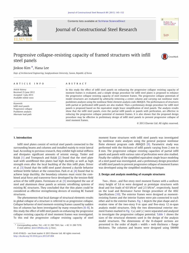
Two-, three-, and five-story steel moment frames with a uniformstory height of 3.6 m were designed as prototype structures withdead and live loads of 4.0 kN/m2 and 2.5 kN/m2, respectively, basedon the Load and Resistance Factor Design procedure of the AISCSpecifications [10]. The exterior frames were designed as moment-resisting frames and the interior frames were pin-connected to eachother and to the exterior frames. Fig. 1 depicts the plan shape and el-evation view of the two-story 9 m span and five-story 12 m-spananalysis model structures. Only the two dimensional exterior mo-ment frames marked in Fig. 1(a) and (c) were separated and analyzedto investigate the progressive collapse potential. Table 1 shows thesizes of the structural elements used in the design of the analysismodel structures. The dimensions of the H-shaped sections arepresented in the order of depth × width × web thickness × flangethickness. The columns and beams were designed using SM490
2@9 m
2@9 m
(a) Plan of 2-story model (b) Elevation of 2-story model
(c) Plan of 5-story model (d) Elevation of 5-story model
2@9 m
Fig. 1. Structural plan and elevation of analysis model structures.
146 J. Kim, H. Lee / Journal of Constructional Steel Research 89 (2013) 145–152
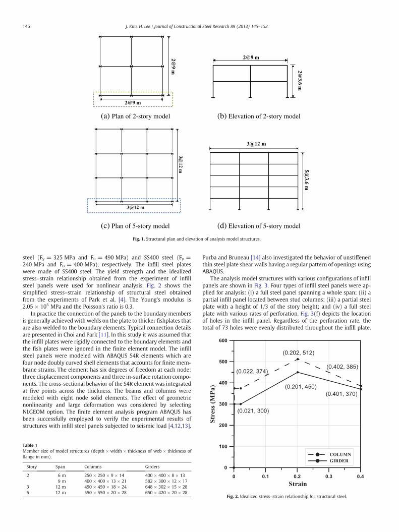
steel (Fy = 325 MPa and Fu = 490 MPa) and SS400 steel (Fy =240 MPa and Fu = 400 MPa), respectively. The infill steel plateswere made of SS400 steel. The yield strength and the idealizedstress–strain relationship obtained from the experiment of infillsteel panels were used for nonlinear analysis. Fig. 2 shows thesimplified stress–strain relationship of structural steel obtainedfrom the experiments of Park et al. [4]. The Young's modulus is2.05 × 105 MPa and the Poisson's ratio is 0.3.
In practice the connection of the panels to the boundary membersis generally achieved with welds on the plate to thicker fishplates thatare also welded to the boundary elements. Typical connection detailsare presented in Choi and Park [11]. In this study it was assumed thatthe infill plates were rigidly connected to the boundary elements andthe fish plates were ignored in the finite element model. The infillsteel panels were modeled with ABAQUS S4R elements which arefour node doubly curved shell elements that accounts for finite mem-brane strains. The element has six degrees of freedom at each node:three displacement components and three in-surface rotation compo-nents. The cross-sectional behavior of the S4R element was integratedat five points across the thickness. The beams and columns weremodeled with eight node solid elements. The effect of geometricnonlinearity and large deformation was considered by selectingNLGEOM option. The finite element analysis program ABAQUS hasbeen successfully employed to verify the experimental results ofstructures with infill steel panels subjected to seismic load [4,12,13].
Table 1Member size of model structures (depth × width × thickness of web × thickness offlange in mm).
Story Span Columns Girders
2 6 m 250 × 250 × 9 × 14 400 × 400 × 8 × 139 m 400 × 400 × 13 × 21 582 × 300 × 12 × 17
3 12 m 450 × 450 × 18 × 24 648 × 302 × 15 × 285 12 m 550 × 550 × 20 × 28 650 × 420 × 20 × 28
Purba and Bruneau [14] also investigated the behavior of unstiffenedthin steel plate shear walls having a regular pattern of openings usingABAQUS.
The analysis model structures with various configurations of infillpanels are shown in Fig. 3. Four types of infill steel panels were ap-plied for analysis: (i) a full steel panel spanning a whole span; (ii) apartial infill panel located between stud columns; (iii) a partial steelplate with a height of 1/3 of the story height; and (iv) a full steelplate with various rates of perforation. Fig. 3(f) depicts the locationof holes in the infill panel. Regardless of the perforation rate, thetotal of 73 holes were evenly distributed throughout the infill plate.
Fig. 2. Idealized stress–strain relationship for structural steel.

(a) Full infill plates (b) Partial infillplates at center
(c) Partial infill plates at sides
(d) Partial infill plates with 1/3 of story height
(e) Infill plates with holes
(f) Location of holes
Fig. 3. Configuration of infill steel panels used in the analysis.
Fig. 4. Pushdown curves of the two-story 9 m span model structure with full infillpanels.
147J. Kim, H. Lee / Journal of Constructional Steel Research 89 (2013) 145–152
The diameter of a hole was increased from 107 mm in the case of 10%perforation rate to 213 mm in the 40% perforation rate. The distancebetween the beam or column flanges to the centers of the holesnearest to the boundary elements is 500 mm, and the center to centerdistance between two holes is 800 mm. In practice the partial steelpanels shown in Fig. 3(b) and (c) may be applied to accommodateopenings such as doors or windows, respectively. The steel panelswith holes may be used to provide openings or to save steel tonnage.
For simulation of progressive collapse, nonlinear static pushdownanalyses were carried out by removing the first story center columnand gradually increasing the vertical displacement in the location ofthe removed column. For nonlinear static analysis the amplified grav-ity load of 2.0(Dead load + 0.25 × Live load) was applied followingthe recommendations of the GSA guidelines [15]. The factor 2.0 is ap-plied to consider the dynamic effect associated with sudden removalof a column. The steel plates are expected to buckle along compres-sive diagonals under relatively small shear forces. After buckling,the story shear forces are resisted by the plates through formationof a tension field. To simulate the buckling of the compression diago-nal in the plates, slight out-of-plane deformation in the shape of firstbuckling mode was provided prior to pushdown analysis.
3. Pushdown analysis results of model structures with andwithout infill panels
In this section pushdown analyses of the model structures withtwo-story 9 m span length and five-story 12 m span length were car-ried out to investigate their progressive collapse resisting capacitywhen the first story center column was removed from eachstructure. Fig. 4 depicts the pushdown curves of the two-storymodel structure installed with full infill plates with their thicknessvarying from 2 mm to 8 mm. The first story middle column was arbi-trarily removed and the applied force, normalized by the imposed
gravity load specified in the GSA Guidelines, vs. the vertical displace-ment relationship was plotted. The pushdown curve of the bare framewithout steel panels was also plotted for comparison. It can be ob-served that the maximum load factor of the bare frame fails toreach 1.0, which implies that the structures lack enough strength toresist the GSA specified load when a column is suddenly removed.When full steel panels with thickness of 2 mm were installed, themaximum strength exceeded the load factor of 1.0, implying thatthe structure can resist the specified load combination. The strengthfurther increased significantly as the thickness increased to 4 mm.

(a) t=2mm
(b) t=4mm
(c) t=6mm
Fig. 5. Von-Mises stress contours in the infill steel plate when the vertical displacementreached 50 mm.
Fig. 6. Pushdown curves of the two-story 9 m span model structure with 4 mm thickpartial infill panels.
148 J. Kim, H. Lee / Journal of Constructional Steel Research 89 (2013) 145–152
However as the thickness increased to 6 mm and 8 mm the increasein strength became only minute. Fig. 5 shows the Von-Mises stresscontours in the steel panels when the vertical deflection at the topof the removed column reached 100 mm. The formation of tensionfield is clearly visible in the infill panels. It also can be observed thatas the thickness of infill plate increases the stress concentration inthe steel plates decreases gradually while the stress in the columnsincreases.
The pushdown analysis results of the two-story structure with4 mm thick steel plate located only at part of the span as shown inFig. 3(b) and (c) are depicted in Fig. 6. It can be observed that thestrength of the structure with partial steel plates having only 1/3 ofthe full width located at the center of the span is almost twice thatof the bare frame and is enough to resist the progressive collapse.When two partial plates were installed at both sides of a span, thestrength increased slightly; however considering the doubled amountof steel plate, the increase in strength is not significant. Fig. 7 showsthe Von-Mises stress contours in the partial steel plates at the verticaldeflection of 100 mm. It can be observed that the partial infill plateplaced at the center of the span is more highly stressed than thoseplaced at the sides of the span when the structure is subjected tothe same vertical deflection. In addition to the possibility of providingopenings for windows or doors, the partial steel infill wall may be ef-fective in preventing progressive collapse with reduced steel. Fig. 8depicts the pushdown curve of the 9 m span structure with partialinfill plates having 1/3 of story height (h = 1.2 m) and those of thestructure installed with full infill plates. The added horizontal beamsare H-shaped sections with the size of 175 × 90 × 5 × 8 (mm). It
can be observed that, even though the overall strength is significantlysmaller than that of the structure with full infill panels, the maximumstrength exceeds the load factor of 1.0.
In case the minimum thickness of infill plates required to preventprogressive collapse of a structure is smaller than the minimumthickness of plates produced by a manufacturer, an economic solutioncan be achieved by perforating holes in the infill plates and thus re-ducing overall weight [16]. Fig. 9 shows the pushdown curves of thetwo-story 9 m span model structure installed with 4 mm thick steelinfill plates with regularly spaced circular holes. It can be observedthat the strength of the model structure keeps decreasing as the per-foration rate increases. However even in the structure with infillpanels having 40% perforation rate, the yield strength exceeded theimposed load specified in the GSA Guidelines. Fig. 10 shows theVon-Mises stress contours in the steel plates with holes when thevertical displacement reached 10 cm. It can be observed in Fig. 5(a)that stress is concentrated along the tension fields when there areno holes in the plates. In the infill plates with holes, the formationof tension field is not as distinct as in the infill panels without holes,especially when the perforation rate increases to 40%.
Fig. 11 shows the pushdown curves of a 5-story 12 m span modelstructure with and without infill steel plates when a first story interi-or column was removed. It can be seen that the progressive collapseresisting capacity of the bare frame is not satisfactory as in the caseof the two-story structure analyzed previously. When 2 mm thickinfill panels were placed only in the second story, the maximumload factor at the vertical displacement specified in the GSA guide-lines as the limit state did not reach 1.0. The maximum load factorreached 1.0 when the steel panels were installed in the second andthe fourth stories. Fig. 12 depicts the Von-Mises stress contours inthe infill panels installed in the five-story structure at the vertical dis-placement of 100 mm. The formation of tension field can be observedin the panels located in the spans from which a column is removed.
4. Simplified modeling of infill plates
For analysis of a structure with infill steel plates, the finite elementmodeling may produce the most accurate results. However as sophis-ticated modeling technique and significant amount of computationtime are required in the finite element modeling and analysis, simpli-fied modeling techniques such as a strip model or an equivalent sin-gle brace model are frequently used for structural analysis anddesign of structures with infill steel plates. In the strip model, the

Fig. 7. Distribution of stress at partial steel plates when vertical displacement reached 100 mm.
149J. Kim, H. Lee / Journal of Constructional Steel Research 89 (2013) 145–152
steel plate is replaced by a series of diagonal elements called strips[1,17]. Another simplified model for an infill steel plate, an equivalentsingle brace model, was proposed by Thorburn et al. [18]. In thismodel a steel plate is modeled as a single diagonal brace with anequivalent property to the steel plate. Using the elastic strain energyformulation, they derived the area of the equivalent brace based onfully developed tension field theory as follows:
A ¼ th sin22α2 sinϕ sin 2ϕ
ð1Þ
Fig. 8. Pushdown curves of the two-story frame installed with partial steel plates with1/3 of story height.
Fig. 9. Pushdown curves of the two-story structure with 4 mm thick infill plates withvarious perforation rates.
where t is the thickness of a steel plate, h is the story height, ϕ is theangle between horizontal axis and the diagonal tension brace, andα is the inclination angle of the tension field to the horizontal axis.For progressive collapse, the inclination angle of the tension field tothe horizontal axis, α, is obtained as follows based on the principleof least work [1]:
tan4α ¼1þ th
2Ab
1þ tL1Ac
þ L3
360Ibh
! ð2Þ
where L is the center-to-center distance between the boundary col-umns; Ab and Ac are the cross-sectional areas of the beam and the col-umn, respectively; and Ib is the moment of inertia of the boundarybeam.
Fig. 13 depicts the pushdown curves of the two-story 6 m and 9 mspan model structures with infill steel panels modeled by finite
(a) Perforation rate 20%
(b) Perforation rate 40%
Fig. 10. Von-Mises stress contours of steel infill plates with perforations at the verticaldisplacement of 100 mm.
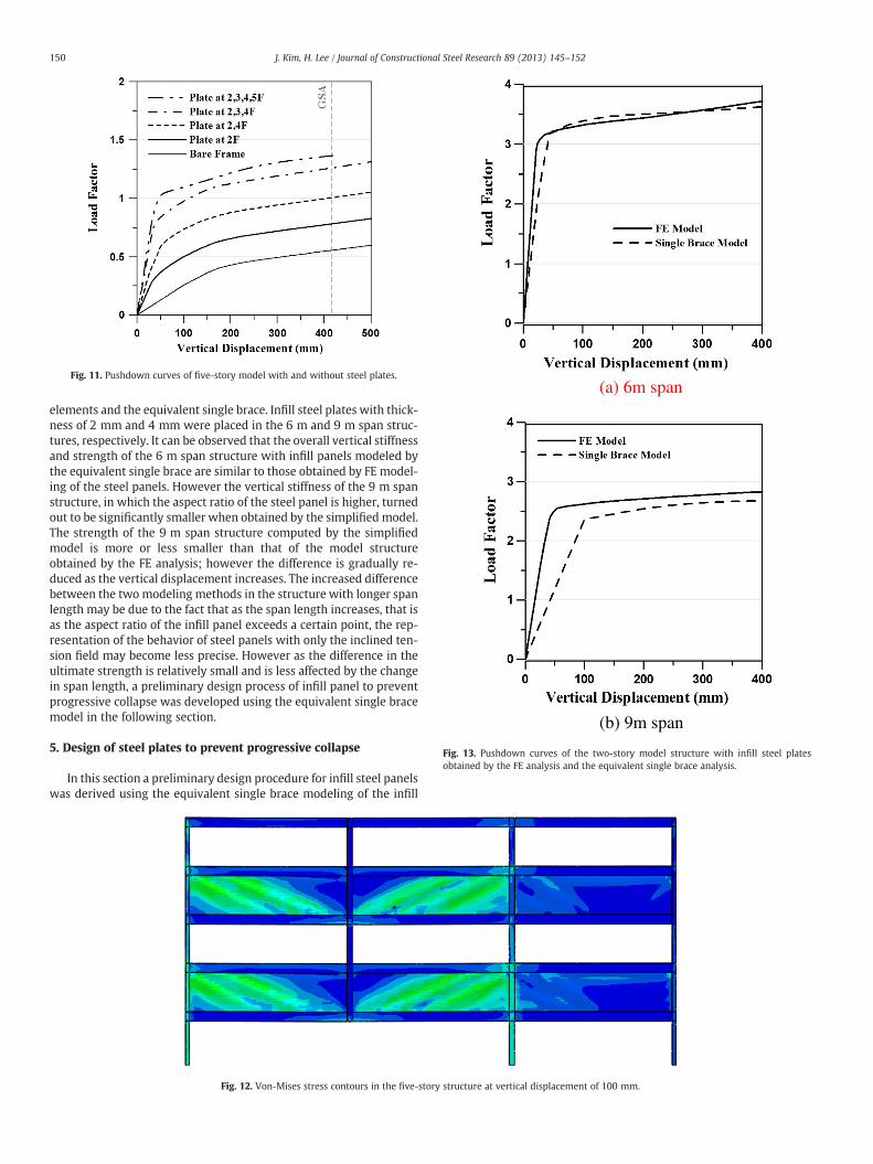
Fig. 11. Pushdown curves of five-story model with and without steel plates.(a) 6m span
(b) 9m span
Fig. 13. Pushdown curves of the two-story model structure with infill steel platesobtained by the FE analysis and the equivalent single brace analysis.
150 J. Kim, H. Lee / Journal of Constructional Steel Research 89 (2013) 145–152
elements and the equivalent single brace. Infill steel plates with thick-ness of 2 mm and 4 mm were placed in the 6 m and 9 m span struc-tures, respectively. It can be observed that the overall vertical stiffnessand strength of the 6 m span structure with infill panels modeled bythe equivalent single brace are similar to those obtained by FE model-ing of the steel panels. However the vertical stiffness of the 9 m spanstructure, in which the aspect ratio of the steel panel is higher, turnedout to be significantly smaller when obtained by the simplified model.The strength of the 9 m span structure computed by the simplifiedmodel is more or less smaller than that of the model structureobtained by the FE analysis; however the difference is gradually re-duced as the vertical displacement increases. The increased differencebetween the twomodeling methods in the structure with longer spanlength may be due to the fact that as the span length increases, that isas the aspect ratio of the infill panel exceeds a certain point, the rep-resentation of the behavior of steel panels with only the inclined ten-sion field may become less precise. However as the difference in theultimate strength is relatively small and is less affected by the changein span length, a preliminary design process of infill panel to preventprogressive collapse was developed using the equivalent single bracemodel in the following section.
5. Design of steel plates to prevent progressive collapse
In this section a preliminary design procedure for infill steel panelswas derived using the equivalent single brace modeling of the infill
Fig. 12. Von-Mises stress contours in the five-story structure at vertical displacement of 100 mm.

Fig. 14. Relation of vertical deflection and element force of an equivalent single brace.
(a) Finite element model
(b) Equivalent single brace model
Fig. 16. Configuration of three-story analysis model structure with infill panels for val-idation of simplified modeling of infill steel panels.
151J. Kim, H. Lee / Journal of Constructional Steel Research 89 (2013) 145–152
panels. The design procedure was applied to the three-story 12 mspan model structure and the validity of the procedure was investi-gated by finite element analysis. The design objective for retrofit isto determine the required thickness of steel panels to achieve themaximum load factor of 1.0 when a column is removed. This impliesthat the structure is retrofitted using infill panels in such a way that itcan resist the imposed load 2(DL + 0.25LL) specified in the GSAguidelines. Fig. 14 shows the configuration of an equivalent singlebrace subjected to vertical displacement d at one side. From theequivalence between the vertical deflection of the plate and the elon-gation of the equivalent diagonal brace, the vertical force acting onthe equivalent single brace subjected to vertical displacement d canbe obtained using the following relationship:
Fvertical ¼EA sin3ϕ
hd ð3Þ
where E is the modulus of elasticity, A is the cross-sectional area ofthe equivalent brace, h is the height of the steel plate, and d is the ver-tical deflection for which the collapse limit state specified in the GSAguidelines can be used. The rotation limit state for moment framesspecified in the GSA guidelines is 0.035 rad. The thickness of thesteel plates is determined in such a way that the total strength ofthe plates at a limit state is equal to the difference between the globalstrength of the bare frame and the target strength of the retrofittedframe, which is the GSA specified imposed load. To achieve this de-sign objective it is required that the vertical strength of the equivalentbrace is equal to the required strength of the system:
Fvertical ¼nEA sin3ϕ
hd ¼ ΔLoad ð4Þ
where n is the number of steel plates installed in the bays from whicha column is removed, and the required strength ΔLoad is obtained
Fig. 15. Target strength of the frame for design of infill steel panels.
from the pushdown curve as depicted in Fig. 15. From Eqs. (1) and(4), the required area of each equivalent brace can be obtained as fol-lows:
A ¼ ΔLoadð ÞhndE sin3ϕ
¼ th sin22α2 sinϕ � sin2ϕ : ð5Þ
Then the required thickness of each infill plate to prevent progres-sive collapse is computed as:
t ¼ 2 ΔLoadð Þ sin2ϕndE sin2ϕ sin22α
� � : ð6Þ
The above procedure for design of infill steel plates was applied tothe three-story 12 m span structure shown in Fig. 16. The sizes of thestructural members were shown in Table 1. According to the push-down curve of the bare frame shown in Fig. 17, the structure is vul-nerable for progressive collapse when a first-story center column isremoved. To enhance progressive collapse resisting capacity, infillsteel plates were to be installed in the second story. From the push-down curve of the bare frame and the given target strength, the
Fig. 17. Pushdown curves of the three-story model structure with infill plates designedusing Eq. (6).

152 J. Kim, H. Lee / Journal of Constructional Steel Research 89 (2013) 145–152
thickness of infill steel plates required to achieve the maximum loadfactor of 1.0 was computed using Eq. (6). In order to reach the targetload factor, the thickness of the infill plates was computed as 4.4 mm.The model structure was retrofitted with the 4 mm-thick steel infillplates in the second story and was analyzed with their first story cen-ter column removed. Fig. 17 shows the pushdown curves of themodel structure before and after the retrofit. The steel plates in theretrofitted structures were modeled by both the finite and the equiv-alent single braces in the pushdown analysis. It can be observed thatthe maximum load factor of the model structure retrofitted with steelplates reached the target load factor of 1.0 at the displacement spec-ified in the GSA Guidelines as a limit state. Even though the stiffnessof the structure predicted by the equivalent single brace model issomewhat smaller than that obtained by the FE analysis, as also ob-served in Fig. 14 in the case of the two-story 9 m span structure, themaximum strength of the structure generally corresponded wellwith that of the FE model.
6. Conclusions
In this study the effect of infill steel panels on enhancing progres-sive collapse resisting capacity of steel moment frames was in-vestigated, and a simple design procedure for infill steel panels wasproposed to ensure safety against progressive collapse caused by sud-den removal of a column. The progressive collapse potentials wereevaluated based on arbitrary column removal scenario. The accuracyof the equivalent single brace modeling techniques of steel panelswas investigated in comparison with the analysis results of finite ele-ment modeling.
The analysis results showed that the infill steel panels were effec-tive in reducing the progressive collapse potential of moment framescaused by sudden removal of a column. It was observed that as thethickness of the steel panels increased the progressive collapseresisting capacity also increased. However when the thickness ofthe steel panels increased higher than a certain level the increase inthe progressive collapse resisting capacity did not increase propor-tionally because of yielding of columns. Even the partial infill panelsor panels with perforation were somewhat effective in protectingthe structures against progressive collapse. The simplified modelingof steel panels utilizing an equivalent single brace generally cor-responded well with the finite element model, and the preliminarydesign procedure of steel panels using the single brace model turned
out to be effective in estimating the minimum thickness of steelpanels required to ensure safety against progressive collapse.
Acknowledgment
This research was financially supported by a grant (Code#'09 R&DA01) funded by the Ministry of Land, Infrastructure, and Transport ofKorean government.
References
[1] Timler PA, Kulak GL. Experimental study of steel plate shear walls. Structural Eng.Rep. No. 114. Edmonton, Alberta., Canada: Dept. of Civil Engineering, Univ. ofAlberta; 1983.
[2] Tromposch EW, Kulak GL. Cyclic and static behavior of thin panel steel plate shearwalls. Structural engineering rep. 145. Edmonton, Alberta, Canada: Dept. of CivilEngineering, Univ. of Alberta; 1987.
[3] Driver RG, Kulak GL, Kennedy DJ, Elwi AE. Cyclic test of a four-story steel plateshear wall. J Struct Eng 1998;124(2):112–30.
[4] Park HG, Kwack JH, Jeon SW, Kim WG, Choi IR. Framed steel plate wall behaviorunder cyclic lateral loading. J Struct Eng 2007;133(3):378–88.
[5] Formisano A, De Matteis G, Mazzolani FM. Numerical and experimental behaviorof a full-scale RC structure upgraded with steel and aluminium shear panels.Comput Struct 2010;88:1348–60.
[6] Kaewkulchai G, Williamson EB. Dynamic behavior of planar frames during pro-gressive collapse. 16th ASCE Engineering Mechanics Conference; 2003.
[7] Khandelwal K, El-Tawil S. Progressive collapse of moment resisting steel framebuildings. Proceedings of the Structures Congress and the Forensic EngineeringSymposium, New York; 2005.
[8] Kim J, Kim T. Assessment of progressive collapse-resisting capacity of steelmoment frames. J Constr Steel Res 2009;61(1):169–79.
[9] Hibbitt, Karlsson, and Sorenson, Inc. HKS. ABAQUS standard, version 6.4; 2003[Pawtucket, R.I.].
[10] AISC. Load and resistance factor design specification for structural steel buildings.Chicago: American Institute of Steel Construction; 2000.
[11] Choi IR, Park HG. Steel plate shear walls with various infill plate designs. J StructEng 2009;135(7):785–96.
[12] Driver RG, Kulak GL, Kennedy DJL, Elwi AE. Seismic behavior of steel plate shearwalls. rep. no. 215. Edmonton, Alta: Dept. of Civil Engineering, Univ. of Alberta;1997.
[13] Schumacher A, Grondin GY, Kulak GL. Connections of infill panels in steel plateshear walls. Structural engineering report no. 217. University of Alberta; 1997.
[14] Purba R, Bruneau M. Finite-element investigation and design recommendationsfor perforated steel plate shear walls. J Struct Eng 1993;119(2):588–605.
[15] GSA. Progressive collapse analysis and design guidelines for new federal officebuildings and major modernization project. The U.S. General Services Administra-tion; 2003.
[16] Purba R, Bruneau M. Finite-element investigation and design recommendation forperforated steel plate shear walls. J Struct Eng ASCE 2009;135(11):1367–76.
[17] Elgaaly M, Caccese V, Du C. Post-buckling behavior of steel-plate shear wallsunder cyclic loads. J Struct Eng 1993;119(2):588–605.
[18] Thorburn LJ, Kulak GL, Montgomery CJ. Analysis of steel plate shear walls, struc-tural engineering report 107. University of Alberta; 1983.