Journal Bearing oil selection
25
FACULTY OF MECHANICAL ENGINEERING SKMM 4353 LUBRICATION CASE STUDY 1 MUHAMMAD NADZMI BIN MOHAMMAD NAZARI A11KM0260 SECTION 01 EN. MOHD. ZUBIL BIN BAHAK
-
Upload
nadzmi-nazari -
Category
Documents
-
view
55 -
download
1
description
Case study on choosing lubricating oil for journal bearing with some misalignment.
Transcript of Journal Bearing oil selection

FACULTY OF MECHANICAL ENGINEERING
SKMM 4353 LUBRICATION
CASE STUDY 1
MUHAMMAD NADZMI BIN MOHAMMAD NAZARI
A11KM0260
SECTION 01
EN. MOHD. ZUBIL BIN BAHAK

1
TABLE OF CONTENTS
1.0 INTRODUCTION ............................................................................................ 2
2.0 PROBLEM ANALYSIS ................................................................................... 2
3.0 ANALYSIS ....................................................................................................... 3
3.1 Sample Calculation ........................................................................................ 3
3.1.1 Performance Analysis ............................................................................ 4
3.1.2 Calculation of Temperature.................................................................... 6
3.1.3 Calculation of Minimum Film Thickness .............................................. 9
3.1.4 Further Design Considerations ............................................................. 10
3.2 Calculation for Changing of Lubricating Oil .............................................. 11
3.2.1 Performance Analysis .......................................................................... 11
3.2.2 Calculation of Temperature.................................................................. 14
3.2.3 Calculation of Minimum Film Thickness ............................................ 16
3.2.4 Further Design Considerations ............................................................. 17
4.0 RESULT AND DISCUSSION ....................................................................... 18
4.1 Lubricating Oil ISO VG 32 ......................................................................... 20
4.2 Lubricating Oil ISO VG 68 ......................................................................... 22
5.0 CONCLUSION ............................................................................................... 24

2
1.0 INTRODUCTION
A possible by-product in the aluminium smelting process is fluorine and adequate
ventilation of plant is most important from a health hazard point of view.
Centrifugal fans are commonly employed to discharge ventilation air to a chimney
stack.
In the particular plant, the fan motors have liquid film journal bearings with specific
specification. The plant operators find that some bearings operate adequately whilst
others fail due to wiping of the white metal bearing lining. The failure might due to
many reasons, thus, calculations and proving are needed to be done in order to
determine the causes and to determine which specifications are needed to be
configured.
2.0 PROBLEM ANALYSIS
The journal bearings specification given might have problems due to
misalignment and is not safe. Calculations on performance, temperature and film
thickness must be determined so that the specifications given can be changed in
order for the bearing to be safe to operate.
3
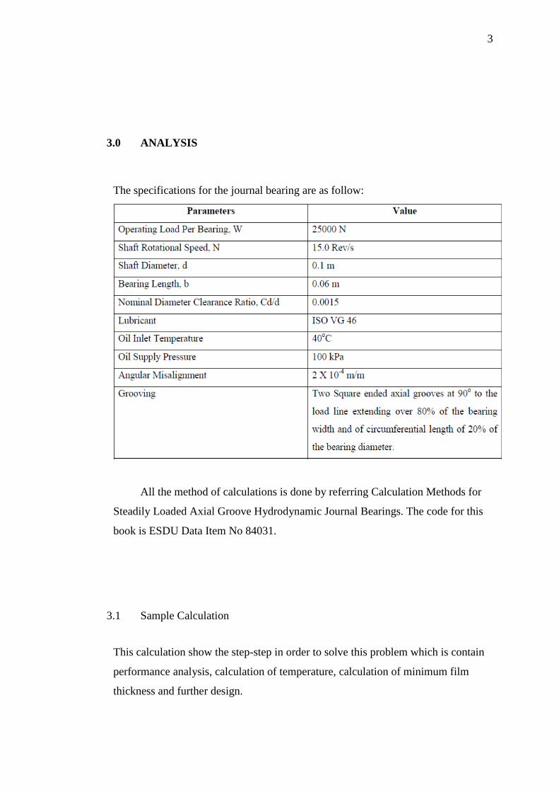
3.0 ANALYSIS
The specifications for the journal bearing are as follow:
All the method of calculations is done by referring Calculation Methods for
Steadily Loaded Axial Groove Hydrodynamic Journal Bearings. The code for this
book is ESDU Data Item No 84031.
3.1 Sample Calculation
This calculation show the step-step in order to solve this problem which is contain
performance analysis, calculation of temperature, calculation of minimum film
thickness and further design.
4
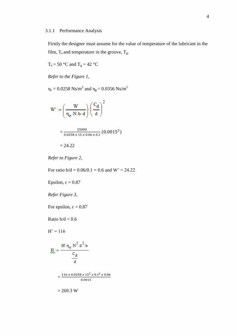
3.1.1 Performance Analysis
Firstly the designer must assume for the value of temperature of the lubricant in the
film, Te and temperature in the groove, Tg.
Te = 50 °C and Tg = 42 °C
Refer to the Figure 1,
ηe = 0.0258 Ns/m2 and ηg = 0.0356 Ns/m
2
=
= 24.22
Refer to Figure 2,
For ratio b/d = 0.06/0.1 = 0.6 and W’ = 24.22
Epsilon, ԑ = 0.87
Refer Figure 3,
For epsilon, ԑ = 0.87
Ratio b/d = 0.6
H’ = 116
=
= 269.3 W
5
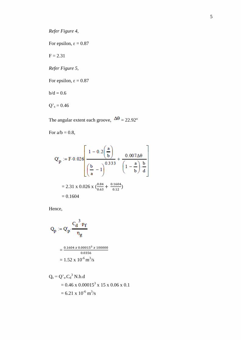
Refer Figure 4,
For epsilon, ԑ = 0.87
F = 2.31
Refer Figure 5,
For epsilon, ԑ = 0.87
b/d = 0.6
Q’s = 0.46
The angular extent each groove, = 22.92
For a/b = 0.8,
= 2.31 x 0.026 x
= 0.1604
Hence,
=
= 1.52 x 10⁻⁶
m3/s
Qs = Q’s.Cd3 N.b.d
= 0.46 x 0.000153 x 15 x 0.06 x 0.1
= 6.21 x 10⁻⁶
m3/s

6
Q = Qp +
Qs
= 1.52 x 10⁻⁶
+ (0.8)( 6.21 x 10⁻⁶
)
= 6.49 x 10⁻⁶
m3/s
Q’r = 0.8 (1 – epsilon, ԑ)
= 0.8 (1 – 0.87)
= 0.104
Qr = Q’r . Cd. N. b. d
= 0.104 x 0.00015 x 15 x 0.06 x 0.1
= 1.404 x 10⁻⁶
m3/s
3.1.2 Calculation of Temperature
The Peclet number is,
=
= 4.218
Z =
=
= 5.31

7
= 1 + (2.75) (
)
= 1.18
= (
)
= 0.4427
= (
)
= 0.955
Using the equation for Q > Qs
C = 1.7 x 10⁶
Te – Tf =
=
( )
= 11.67

8
Therefore,
Te = 11.67 + Tf
= 51.67
Tg – Tf =
(Te – Tf)
=
(50 - 42)
= 2.02
Tg = 2.02 + Tf
= 42.02
The agreement between the assumed and calculated value is acceptable because the
temperature difference is within 2K.
Tmax – Tg = (Te – Tg )
= 1.18 (50 – 42)
= 9.44
Therefore,
Tmax = 9.44 + 42
= 51.44 (acceptable)
Tout – Tf =
=
= 10.81
Tout = 10.81 + 40
= 50.81 (acceptable because not higher than 80 °C)
9
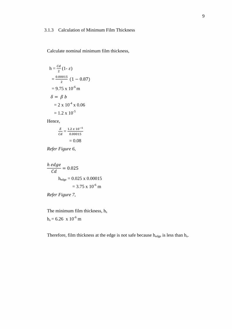
3.1.3 Calculation of Minimum Film Thickness
Calculate nominal minimum film thickness,
h =
(1- )
=
= 9.75 x 10⁻⁶
m
= 2 x 10-4
x 0.06
= 1.2 x 10⁻⁵
Hence,
=
= 0.08
Refer Figure 6,
hedge = 0.025 x 0.00015
= 3.75 x 10⁻⁶
m
Refer Figure 7,
The minimum film thickness, hs
hs = 6.26 x 10⁻⁶
m
Therefore, film thickness at the edge is not safe because hedge is less than hs.

10
3.1.4 Further Design Considerations
Checking the laminar operation,
Re =
=
= 11.97
Re√
= 11.97 √
= 0.4634
From Sketch 1, the value is still inside laminar region.
Checking for stability of the bearing and whirl problem,
=
= 3.44 x 10⁻³
The value is less than 0.2 and will not encounter whirl problem.

11
3.2 Calculation for Changing of Lubricating Oil
These calculations are specified for changing of lubricating oil from ISO VG 46 to
ISO VG 32. Any requirement of changing of lubricating oil in the future can be
done by using the same method.
3.2.1 Performance Analysis
Te = 50 °C and Tg = 40 °C
Refer to Figure 1,
ηe = 0.018 Ns/m2 and ηg = 0.027 Ns/m
2
=
= 34.72
Refer to Figure 2,
For ratio b/d = 0.06/0.1 = 0.6 and W’ = 34.72
Epsilon, ԑ = 0.895
Refer Figure 3,
For epsilon, ԑ = 0.895
Ratio b/d = 0.6
H’ = 131

12
=
= 212.22 W
Refer Figure 4,
For ԑ = 0.895
F = 2.23
Refer Figure 5,
For ԑ = 0.895
b/d = 0.6
Q’s = 0.45
The angular extent each groove, = 22.92
For the a/b = 0.8,
= 2.23 x 0.026 x
= 0.1548

13
Hence,
=
= 1.935 x 10⁻⁶
m3/s
Qs = Q’s.Cd3 N.b.d
= 0.45 x 0.000153 x 15 x 0.06 x 0.1
= 6.075 x 10⁻⁶
m3/s
Q = Qp +
Qs
= 1.935 x 10⁻⁶
+ (0.8)( 6.075 x 10⁻⁶
)
= 6.795 x 10⁻⁶
m3/s
Q’r = 0.8 (1 – epsilon, ԑ)
= 0.8 (1 – 0.895)
= 0.084
Qr = Q’r . Cd. N. b. d
= 0.084 x 0.00015 x 15 x 0.06 x 0.1
= 1.134 x 10⁻⁶
m3/s

14
3.2.2 Calculation of Temperature
The Peclet number is,
=
= 4.218
Z =
=
= 5.43
= 1 + (2.75) (
)
= 1.19
= (
)
= 0.4372
= (
)
= 0.9525

15
Using the equation for Q > Qs
C = 1.7 x 10⁶
Te – Tf =
=
( )
= 9.16
Therefore,
Te = 9.16 + 40 = 49.16
Tg – Tf =
(Te – Tf)
=
(50-40) = 1.67
Tg = 1.67 + 40 = 41.67
The agreement between the assumed and calculated value is acceptable because the
temperature difference is within 2K.
Tmax – Tg = (Te – Tg)
= 1.19 (50 – 40) = 11.9
Therefore,
Tmax = 11.9 + 40 = 51.9 (acceptable)
Tout – Tf =
=
= 8.03
Tout = 8.03 + 40 = 48.03 (acceptable because not higher than 80 °C)
16
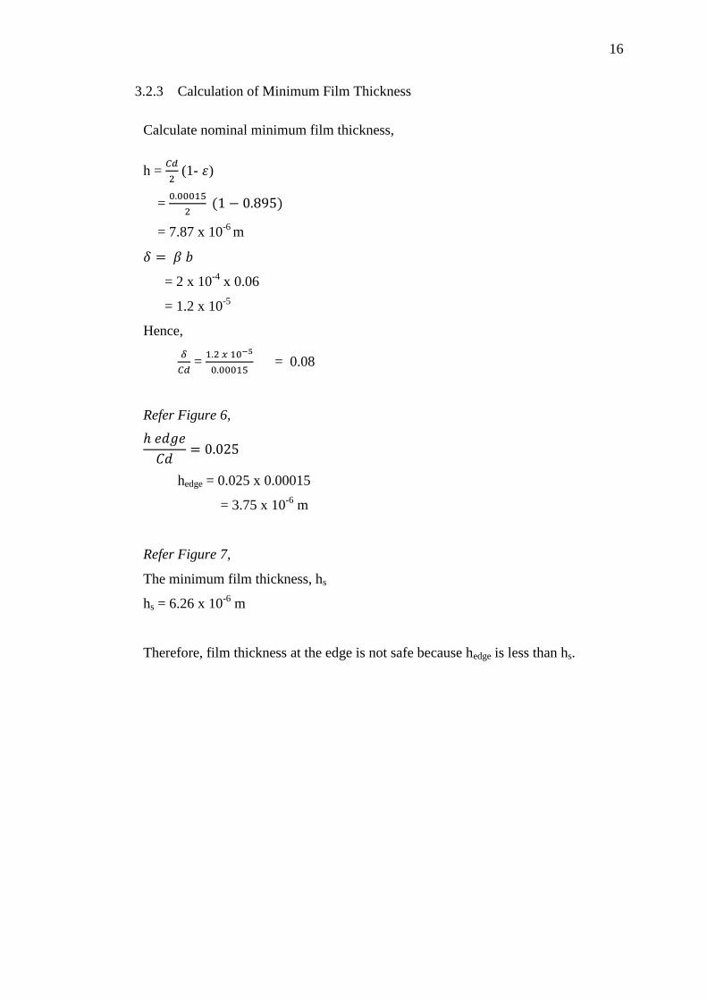
3.2.3 Calculation of Minimum Film Thickness
Calculate nominal minimum film thickness,
h =
(1- )
=
= 7.87 x 10⁻⁶
m
= 2 x 10-4
x 0.06
= 1.2 x 10⁻⁵
Hence,
=
= 0.08
Refer Figure 6,
hedge = 0.025 x 0.00015
= 3.75 x 10⁻⁶
m
Refer Figure 7,
The minimum film thickness, hs
hs = 6.26 x 10⁻⁶
m
Therefore, film thickness at the edge is not safe because hedge is less than hs.
17
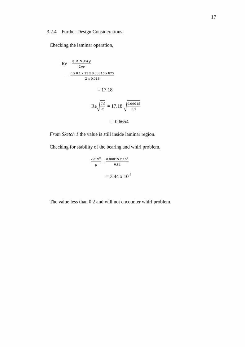
3.2.4 Further Design Considerations
Checking the laminar operation,
Re =
=
= 17.18
Re√
= 17.18 √
= 0.6654
From Sketch 1 the value is still inside laminar region.
Checking for stability of the bearing and whirl problem,
=
= 3.44 x 10⁻³
The value less than 0.2 and will not encounter whirl problem.

18
4.0 RESULT AND DISCUSSION
At this section there will be a summary about the result of the problem and
discussion about the problem.
Parameters 1st iteration 2
nd iteration 3
rd iteration
Te 47 55 50
Tg 42 41 42
Ηe 0.03 0.021 0.0258
Ηg 0.036 0.039 0.036
W’ 20.83 29.76 24.22
0.85 0.882 0.87
H’ 107 123 116
F 2.35 2.28 2.31
1.175 1.17 1.18
Qp 1.53 x 10⁻⁶
1.37 x 10⁻⁶
1.52 x 10⁻⁶
Qs 6.35 x 10⁻⁶
6.07 x 10⁻⁶
6.21 x 10⁻⁶
Qr 1.62 x 10⁻⁶
1.27 x 10⁻⁶
1.404 x 10⁻⁶
Q 6.61 x 10⁻⁶
6.23 x 10⁻⁶
6.49 x 10⁻⁶
H 288.9 232.47 269.3
New Te 51.83 50.22 51.67
New Tg 41.79 42.06 42.02
The iterations are made to find the suitable value of effective temperature of
lubricant in the film, Te, and temperature in the groove, Tg. Both of this value must
be within 2K range from the assumed value to be acceptable to be used.
From the table above we obtained the adequate temperature for Te and Tg which is
51.67 and 42.02. Therefore, we can proceed with this value to calculate its
minimum film thickness and further design.

19
From the value of Te and Tg, we can calculate the maximum temperature, outlet
temperature, minimum film thickness and further design. The maximum
temperature is important because if the bearing temperature is too high, plastic
deformation of bearing material might occur in some operating conditions.
Therefore, it is needed to set the limit for maximum temperature of the bearing. The
outlet temperature is also needed to be determined to avoid deterioration.
Table above shows the calculated value. We can see that, the maximum and
outlet of the temperature for the bearing is 53.4 and 50.81. The maximum
temperature was determined by the material selected because the maximum
allowable bearing temperature depends on the lining material used. For this project
the maximum allowable temperature is 53.4 °C and this value is considered
appropriate. While for the outlet temperature is 50.81 °C and it is acceptable
because for the hydrocarbon oil contact with the atmosphere the recommend
temperature is below 80 °C for normal lubricant life.
From the table also we can see that the minimum safe thickness is 6.26µm. the
nominal minimum film thickness, h and hedge should be more than this value for it
to be safe. But from the analysis that has been done, the nominal minimum film
thickness is safe which is 9.75µm but not the hedge. The hedge not considered safe
because it not exceed the minimum film thickness which is 3.75µm. Therefore, the
existing design is not safe for the operating conditions.
Tmax 53.4
Tout 50.81
h 9.75 x 10⁻⁶
1.2 x 10⁻⁵
0.08
0.025
hedge 3.75 x 10⁻⁶
hs 6.26 x 10⁻⁶

20
4.1 Lubricating Oil ISO VG 32
The calculation is the same with all the previous calculation and shown in table
below for the result.
Parameters 1st iteration 2
nd iteration
Te 40 50
Tg 45 40
Ηe 0.0271 0.018
Ηg 0.022 0.027
W’ 23.06 34.72
0.86 0.895
H’ 112 131
F 2.32 2.23
1.19 1.192
Qp 2.47 x 10⁻⁶
1.935 x 10⁻⁶
Qs 6.11 x 10⁻⁶
6.075 x 10⁻⁶
Qr 1.51 x 10⁻⁶
1.134 x 10⁻⁶
Q 7.36 x 10⁻⁶
6.795 x 10⁻⁶
H 273.2 212.2
New Te 51.68 49.16
New Tg 41.97 41.67
The assumed value shows difference in temperature that less than 2K. Therefore,
we can proceed to calculations to know whether the ISO VG 32 can be used or not.

21
The calculations are the same with the previous calculation and the result is shown
in the table below:
Table above shows the result after calculations of the same method. We can
see that the nominal minimum film thickness, h is above the minimum safe film
thickness, hs. So, the film thickness is safe but not for hedge. We can see that the
value of hedge is lower than hs. So, the oil ISO VG 32 cannot be used for this
condition. Therefore, we need to change the oil to ISO VG 68.
Tmax 50.6
Tout 48.03
h 7.87 x 10⁻⁶
1.2 x 10⁻⁵
0.08
0.015
hedge 2.25 x 10⁻⁶
hs 6.26 x 10⁻⁶

22
4.2 Lubricating Oil ISO VG 68
The calculation is the same with all the previous calculation and shown in table
below for the result.
Parameters 1st iteration 2
nd iteration
Te 55 54
Tg 40 43
Ηe 0.029 0.031
Ηg 0.058 0.051
W’ 21.55 20.16
0.85 0.849
H’ 108 107
F 2.34 2.36
1.19 1.192
Qp 9.45 x 10⁻⁶
1.08 x 10⁻⁶
Qs 6.48 x 10⁻⁶
6.41 x 10⁻⁶
Qr 1.62 x 10⁻⁶
1.63 x 10⁻⁶
Q 6.13 x 10⁻⁶
6.21 x 10⁻⁶
H 281.9 298.5
New Te 52.62 53.12
New Tg 43.35 43.33
The assumed value shows difference in temperature that less than 2K. Therefore,
we can proceed to calculations to know whether the ISO VG 68 can be used or not.

23
The calculations are the same with the previous calculation and the result is shown
in the table below:
As we can see from the table above the value of Tmax and Tout can be
accepted. The value for the nominal minimum film thickness, h and hedge of the
bearing are higher than the value of the minimum film thickness, hs. Therefore, the
bearing with lubricating oil ISO VG 68 can be used with the operating condition.
Now, we can proceed to calculation to determine its stability and the whirl
problem. The results are as shown in the table below:
Reynold number, Re 9.976
Laminar condition, Re√
0.37
Whirl problems,
3.44 x 10⁻³
The Reynold number is calculated and by referring Sketch 1, we can know
the location of the condition to be laminar or turbulence region. Then, as the
bearing is purely gravitational, stability have to be checked whether it will
encounter whirl problem or not. From the result above, we can see that the bearing
is located at the laminar region. The value of whirl problem has not exceeded 0.2
which means the bearing will not encounter whirl problem.
Tmax 50.6
Tout 48.03
H 1.13 x 10⁻⁶
1.2 x 10⁻⁵
0.08
0.045
hedge 6.75 x 10⁻⁶
hs 6.26 x 10⁻⁶

24
5.0 CONCLUSION
First of all, the calculations started with the determination of the temperature
to be assumed for the outlet. The specifications are fixed to what is given.
Lubricating oil ISO VG 46 (default) is used. Then, the assumed value determined is
proven to be correct if the value of temperature difference is less than 2K.
When the temperatures are correct, the calculations can be proceeded to
calculate the film thickness. By using ISO VG 32 as the first choice, it is proven
that the lubricating oil is not suitable as the film thickness at the hedge is lower than
the minimum film thickness, making it not safe. Therefore, the lubricating oil is
needed to be changed.
By using ISO VG 68 as the second choice, the film thickness is more reliable
and is safe as the film thickness at the edge is higher than the minimum film
thickness. Therefore, advanced calculations on Reynold number and the whirl
problem are conducted. By referring Sketch 1, the Reynold number determined is at
laminar region and by more calculation, the bearing is proven to be not encounter
with whirl problem.
In conclusion, the appropriate lubricating oil to be used with the given
specifications is lubricating oil ISO VG 68.