JOSEPH PAXTON: The GREAT STOVE and the CRYSTAL PALACES · JOSEPH PAXTON: The GREAT STOVE and the...
28
JOSEPH PAXTON: The GREAT STOVE and the CRYSTAL PALACES by Brian Roberts, CIBSE Heritage Group Sir Joseph Paxton, 1803-1865 Joseph Paxton was born, the seventh son of a Bedfordshire farmer, on the 3 rd August, 1803, at Milton Bryan near Woburn. At the age of fifteen he obtained employment as a garden boy at Battlesden near Woburn and in 1823 went to the Duke of Somerset at Wimbledon and then to the newly-opened gardens of the Horticultural Society which were then leased from the sixth Duke of Devonshire and adjoined Chiswick House. His work attracted the attention of the Duke and in 1826 Paxton took up the post of Head Gardener at Chatsworth. In 1827 he married Miss Sarah Brown, the housekeeper’s niece. CHATSWORTH Under the patronage of the Duke, Paxton’s career flourished. He travelled widely throughout Europe with the Duke, became a speculator in the railways, and designed many glass structures at Chatsworth, the most famous being the Great Stove where in 1841 he converted the old greenhouse of 1697 and added a heating system. It was said that “seven miles of 4-inch pipes, fired by eight boilers hidden underground were needed to heat this massive edifice, with coal brought to the boilers on an underground railway.”
Transcript of JOSEPH PAXTON: The GREAT STOVE and the CRYSTAL PALACES · JOSEPH PAXTON: The GREAT STOVE and the...

JOSEPH PAXTON: The GREAT STOVE and the CRYSTAL PALACESby Brian Roberts, CIBSE Heritage Group
Sir Joseph Paxton, 1803-1865
Joseph Paxton was born, the seventh son of a Bedfordshire farmer, on the 3rd August, 1803, at Milton Bryan near Woburn. At the age of fifteen he obtained employment as a garden boy at Battlesden near Woburn and in 1823 went to the Duke of Somerset at Wimbledon and then to the newly-opened gardens of the Horticultural Society which were then leased from the sixth Duke of Devonshire and adjoined Chiswick House. His work attracted the attention of the Duke and in 1826 Paxton took up the post of Head Gardener at Chatsworth. In 1827 he married Miss Sarah Brown, the housekeeper’s niece.
CHATSWORTH
Under the patronage of the Duke, Paxton’s career flourished. He travelled widely throughout Europe with the Duke, became a speculator in the railways, and designedmany glass structures at Chatsworth, the most famous being the Great Stove where in 1841 he converted the old greenhouse of 1697 and added a heating system. It was said that “seven miles of 4-inch pipes, fired by eight boilers hidden underground were needed to heat this massive edifice, with coal brought to the boilers on an underground railway.”

Paxton’s Great Stove (Conservatory) at Chatsworth: 84 m long x 37 m wide x 19 m high
Artist’s impression of the Chatsworth Great Stove*
*The word stove derives from Dutch glasshouses which were heated by iron stoves to maintain the temperatures neededby tropical plants in winter. Thus the word “stove” gave its name in England to the building where tropical plants werehoused.

Plan of the Great Stove Heating System
During the Great War the gardeners had gone off to fight and coal was not available for non-essential activities and as no heating was available the plants all died. So the building was deliberately blown up in 1920.

PAXTON’S CHATSWORTH FOUNTAIN
Chatsworth House and the Emperor Fountain
In the early 1840’s, in anticipation of a visit to Chatsworth by Czar Nicolas I of Russia, the Duke of Devonshire decided to construct the world’s highest fountain. The task fell to Paxton who arranged for an eight acre lake (32,000 square metres) to be dug on the moors 110 m above the house to provide the necessary water pressure. It was finished in 1844 but, alas, the Czar never came.
This “Emperor Fountain” reached a height of 70 m powered by the pressure of water dropping some 122 m through a 40 cm iron pipe (15-inches bore and 1.5 inches thick):“The pipe joints were turned and bored, with clip sockets for additional security. The total fall was 381 feet, including 200 ft at 1 in 2, and even so, it was necessary to cut a trench out of solid rock fifteen feet deep in places, and two ponds had to be crossed as well. Near the fountain there was a double-acting valve, which took five minutes to open or close fully, so that shock damage to the pipes should be avoided. The nozzles of the jet itself could be varied for different effects, and were made of brass, and the normal jet would play to 267 ft, or perhaps 280 ft when the reservoir was quite full.”

Details of Paxton’s design for the Emperor Fountain (from Chadwick)

THE HYDE PARK CRYSTAL PALACE
In 1850, the Building Committee of Exhibition Commissioners held an open competition for the design of a building to house the Great Exhibition of the Works of Industry of All Nations to be held in London’s Hyde Park in 1851. Two hundred and forty-five designs were received including one from Isambard Kingdom Brunel who just happened to be one of the judges. Not one was considered to be satisfactory. On Tuesday 11th June, 1850 while at railway meeting, Paxton produced the famous blotting paper sketch that was to be his basis of a new design (he had now been a designer of glass structures for more than twenty years).
Paxton’s sketch of June, 1850
A corner of the Hyde Park Crystal Palace with its external boiler house
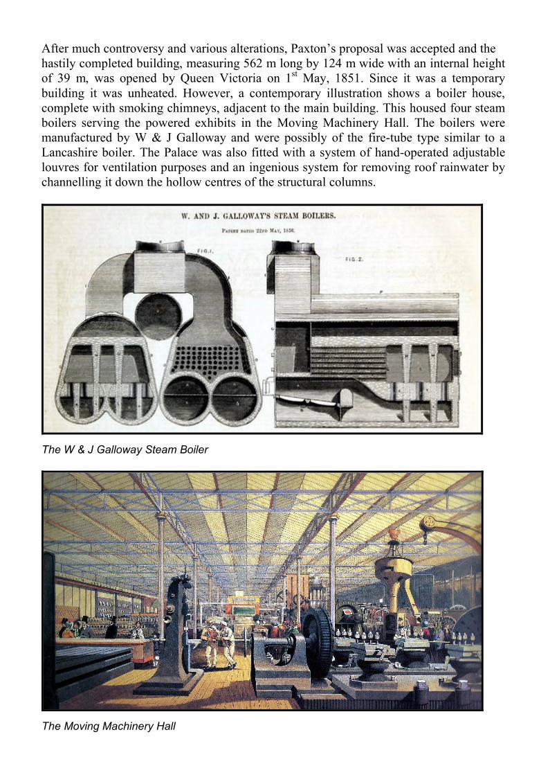
After much controversy and various alterations, Paxton’s proposal was accepted and thehastily completed building, measuring 562 m long by 124 m wide with an internal height of 39 m, was opened by Queen Victoria on 1st May, 1851. Since it was a temporary building it was unheated. However, a contemporary illustration shows a boiler house,complete with smoking chimneys, adjacent to the main building. This housed four steam boilers serving the powered exhibits in the Moving Machinery Hall. The boilers were manufactured by W & J Galloway and were possibly of the fire-tube type similar to a Lancashire boiler. The Palace was also fitted with a system of hand-operated adjustable louvres for ventilation purposes and an ingenious system for removing roof rainwater by channelling it down the hollow centres of the structural columns.
The W & J Galloway Steam Boiler
The Moving Machinery Hall

The original Galloway Company was established in 1806. The brothers William and John manufactured steam engines before 1840 but from 1848 John took a particular interest in steam boilers. The Lancashire type of boiler, which formed the basis of their UK Patent 13532/1851, had been patented earlier by Sir William Fairbairn and John Hetherington in 1844. It is said that W & J Galloway built some 9000 boilers of this type by 1891.
Photograph of unknown date of a W & J Galloway Lancashire type boiler
A coal-fired Galloway steam boiler dating from about 1883

THE FIRST PUBLIC TOILETS
Another feature of the Hyde Park Exhibition was the provision of public toilets, initially for men and later for women also. These were installed by George Jennings and were the first public flush toilets. Jennings design was called “Monkey Closets,” perhaps an unfortunate description. However, it is recorded that over 800,000 visitors each paid a penny to use the “Retiring Rooms” and for their penny “they got a clean seat, a towel, a comb and a shoe shine.” Hence the term “To spend a penny” became a euphemism for going to the toilet.
Jennings was born in 1810 and was an English sanitary engineer and plumber who built alarge and thriving business. He married twice and had fifteen children. During the Crimea War, at the request of Florence Nightingale, he headed the Sanitary Commission that went to the Hospital Barracks at Scutari to improve conditions there. This was partly achieved by flushing the sewers and increasing ventilation. Jennings died in 1882.

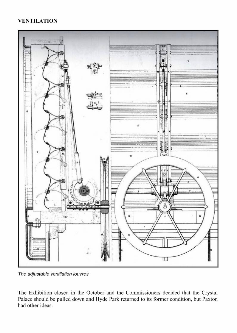
VENTILATION
The adjustable ventilation louvres
The Exhibition closed in the October and the Commissioners decided that the Crystal Palace should be pulled down and Hyde Park returned to its former condition, but Paxton had other ideas.

THE SYDENHAM CRYSTAL PALACE
The Sydenham Crystal Palace and Gardens
Intense arguments raged over the future of the Hyde Park Crystal Palace. Paxton (now Sir Joseph) suggested that with the addition of a heating system it could be turned into a Winter Garden. Others talked of making it a Museum or a Conservatory at Kew or removing it to Battersea Park. Paxton argued that throwing it away would be a wanton destruction of �160,000 worth of public property. However, on 19th April, 1852, the House of Commons voted for its removal.
But Paxton was not to be outdone and having secured a capital of half a million pounds he, with others, floated a company to buy the building and purchase a new site. This new Crystal Palace Company bought the building from the builders, Fox & Henderson, for �70,000 (it was never the property of the Commissioners). The chosen site was Penge Place in Kent which included the summit of the ridge of Sydenham Hill.
This new Crystal Palace was patterned on the Hyde Park building with a number of significant changes. The central transept was raised and two subsidiary transepts added; because of a fall in the ground a basement was necessary and the three-storey structure became a four and in the centre it became a six-storey one. The new building was 490 m long by 95 m wide and 51 m high at the central transept. While less than the Hyde Park building in total floor area and in both length and width, the Sydenham Palace had some 80% more area of glass surface. It also had a massive heating system and a complicated arrangement of twin water towers feeding spectacular fountains and ornamental lakes in the associated gardens.

The interior of the Sydenham Crystal Palace while under construction, November1853
Paxton patterned his heating design on his successful experiments in low-pressure hot water heating at Chatsworth. He worked three hours a day for three weeks on this task.

At Sydenham, “an access roadway ran through the basement storey of the building and here no less than twenty-two boilers were arranged in pairs, each holding 11,000 gallons of water; one extra boiler was added at the north end for a display of tropical plants, two in the lower storeys of each wing and two smaller ones for the fountain basins at each end of the building………. Four pipes of 9-inch diameter were attached to each boiler, two flow and two return and each boiler heated a transverse section of the Crystal Palace: the length of one flow and return was a mile and three-quarters, and the total length of all heating pipes of all kinds was nearly fifty miles.” The manufacturer of the hot water heating boilers has not been determined.
An 1854 Guide noted “…it has remained an unsolved problem how far, and in what quantity, water could be made to travel through pipes –flowing and return by means of the propulsion of heat from the boiler.” This suggests that gravity circulation was employed, i.e. pumps were not used. Was this the case?
To ensure circulation of air throughout the winter “ventilators have been introduced directly from the main building into each furnace, where the air, so brought, being consumed by the fire, the atmosphere in the Palace is continually renewed.”
The North Transept of the Palace in 1854

SYDENHAM CRYSTAL PALACE WATER WORKS
Paxton’s scheme for the water works in the garden was intended to surpass in grandeur both those at Chatsworth and Versailles. He envisaged an Italian Terrace with six fountains and below it a circular fountain, the water-temples, the cascades and twin fountains with jets reaching a height of over 70 m, all with a total of 11,788 jets.
1862 Sydenham Crystal Palace Gardens (East) showing the water features (from Piggott)From right to left the blue areas of water are: (122) Basin, (53) Tidal Lake, (48) South Basin, (77) North Basin,(12) Intermediate Reservoir

1862 Sydenham Crystal Palace Gardens (West) with the water features (from Piggott)Shown are (4) Reservoir (North end of the Palace) and the numerous fountains while the small circles at either end of the main building are the South and North Water Towers.
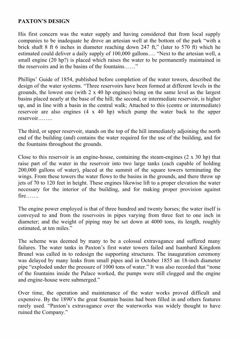
PAXTON’S DESIGN
His first concern was the water supply and having considered that from local supply companies to be inadequate he drove an artesian well at the bottom of the park “with a brick shaft 8 ft 6 inches in diameter reaching down 247 ft,” (later to 570 ft) which he estimated could deliver a daily supply of 100,000 gallons…. “Next to the artesian well, a small engine (20 hp?) is placed which raises the water to be permanently maintained in the reservoirs and in the basins of the fountains……”
Phillips’ Guide of 1854, published before completion of the water towers, described thedesign of the water systems. “Three reservoirs have been formed at different levels in the grounds, the lowest one (with 2 x 40 hp engines) being on the same level as the largest basins placed nearly at the base of the hill; the second, or intermediate reservoir, is higher up, and in line with a basin in the central walk; Attached to this (centre or intermediate) reservoir are also engines (4 x 40 hp) which pump the water back to the upper reservoir……..
The third, or upper reservoir, stands on the top of the hill immediately adjoining the north end of the building (and) contains the water required for the use of the building, and for the fountains throughout the grounds.
Close to this reservoir is an engine-house, containing the steam-engines (2 x 30 hp) that raise part of the water in the reservoir into two large tanks (each capable of holding 200,000 gallons of water), placed at the summit of the square towers terminating the wings. From these towers the water flows to the basins in the grounds, and there throw up jets of 70 to 120 feet in height. These engines likewise lift to a proper elevation the water necessary for the interior of the building, and for making proper provision against fire…….
The engine power employed is that of three hundred and twenty horses; the water itself is conveyed to and from the reservoirs in pipes varying from three feet to one inch in diameter; and the weight of piping may be set down at 4000 tons, its length, roughly estimated, at ten miles.”
The scheme was deemed by many to be a colossal extravagance and suffered many failures. The water tanks in Paxton’s first water towers failed and Isambard Kingdom Brunel was called in to redesign the supporting structures. The inauguration ceremony was delayed by many leaks from small pipes and in October 1855 an 18-inch diameter pipe “exploded under the pressure of 1000 tons of water.” It was also recorded that “none of the fountains inside the Palace worked, the pumps were still clogged and the engine and engine-house were submerged.”
Over time, the operation and maintenance of the water works proved difficult and expensive. By the 1890’s the great fountain basins had been filled in and others featuresrarely used. “Paxton’s extravagance over the waterworks was widely thought to have ruined the Company.”
BRUNEL’S WATER TOWERS
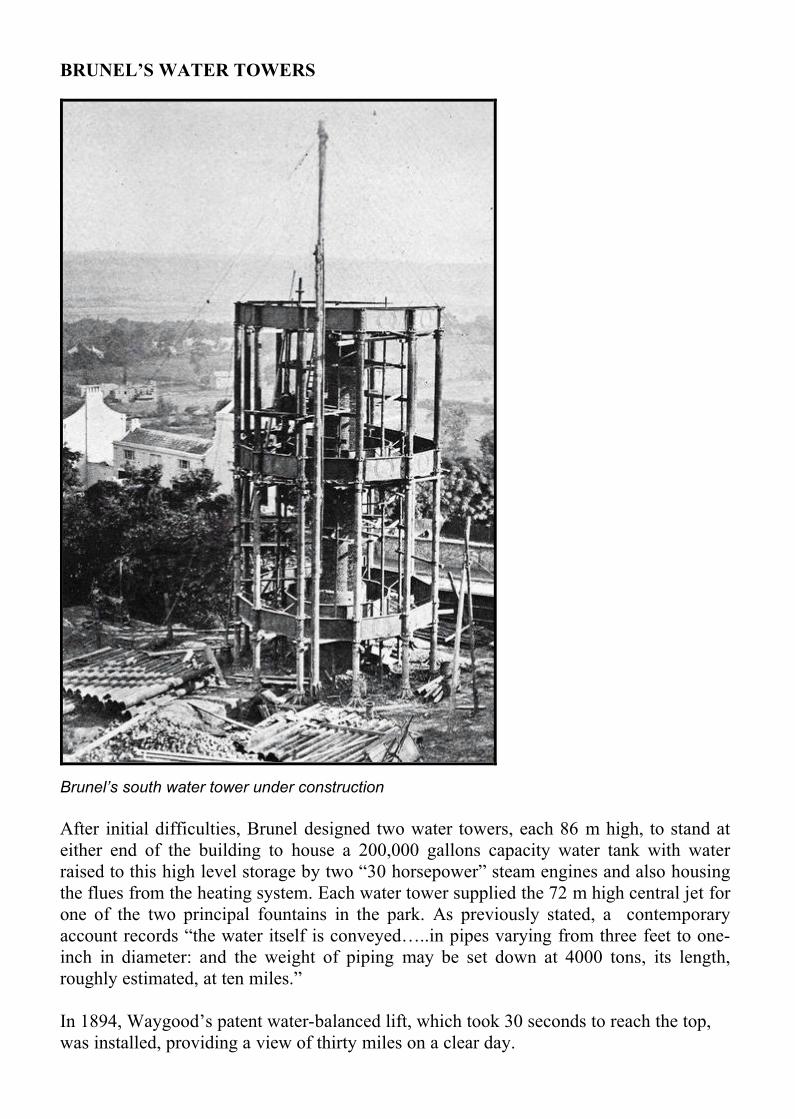
Brunel’s south water tower under construction
After initial difficulties, Brunel designed two water towers, each 86 m high, to stand at either end of the building to house a 200,000 gallons capacity water tank with water raised to this high level storage by two “30 horsepower” steam engines and also housing the flues from the heating system. Each water tower supplied the 72 m high central jet for one of the two principal fountains in the park. As previously stated, a contemporary account records “the water itself is conveyed…..in pipes varying from three feet to one-inch in diameter: and the weight of piping may be set down at 4000 tons, its length, roughly estimated, at ten miles.”
In 1894, Waygood’s patent water-balanced lift, which took 30 seconds to reach the top,was installed, providing a view of thirty miles on a clear day.

View in the Park: Part of the Fountains display- The Cascade Temple, 1854
The Crystal Palace High Level Railway Station, with Brunel’s South Tower behind, 1865

Antique print of the 1856 inauguration of the fountains, supplied from the water towers
Undated photograph of the Sydenham Crystal Palace showing the south water tower

THE FIRE
After Paxton’s death, his Crystal Palace continued but with ever-decreasing revenues until the main building was completely destroyed by fire in 1936. Some say it was a tragic accident, others believe it was an insurance scam. The towers survived, but were demolished in the 1940’s to stop them becoming a London landmark for enemy bombers.

The fire raged out of control
The morning after, the Sydenham Crystal Palace was in ruins, but the water towers were intact

APPENDIX: PAXTON LETTER DESCRIBING INTENDED HEATING SYSTEMFOR THE GREAT CONSERVATORY (From CHATSWORTH LIBRARY)


BIBLIOGRAPHY
1851 Official Catalogue of the Great Exhibition of the Works of All Nations, Spicer Bros, London
1854 Crystal Palace: A Guide to the Palace & Park*, Samuel Phillips, Bradbury & Evans, London (Includes descriptions of the heating systems and the water towers)*Various modern facsimile copies are available
1854 Tallis’s History and Description of the Crystal Palace: And the Exhibition of the World’s Industry in 1851*, (In 3 Volumes), London Printing & Publishing Company*Various modern facsimile copies are available
1961 The Works of Sir Joseph Paxton, 1803-1865, George F Chadwick, Architectural Press, London
1986 The Crystal Palace: A Portrait of Victorian Enterprise, Patrick Beaver, Phillimore, Chichester
1986 The Crystal Palace is on Fire: Memories of the 30th November 1936: The Crystal Palace Foundation, London
1986 Palace of the People, Graham Reeves, Bromley Library Service
1991 Houses of Glass: A Nineteenth Century Building Type, (from the German), Georg Kohlmaier & Barna von Sartory, MIT Press, Cambridge Massachusetts(With information on both Chatsworth’s Great Conservatory or Stove and the Crystal Palace)
1994 Crystal Palace: Joseph Paxton and Charles Fox, John McKean, Phaidon Press, London (Includes detailed drawings of the ventilation louvres)
2000 The Comfort Makers, Brian Roberts, ASHRAE
2004 Palace of the People: The Crystal Palace at Sydenham, 1854-1936, Jan Piggott, C Hurst & Co
2016 W & J Galloway & Sons, from Wikipedia, the free internet encyclopedia (19 pages)

POSTSCRIPT & FURTHER READING
1854 1986
2004

EPILOGUE
Sir Joseph Paxton died in 1865 and is buried at St Peter’s Church in the village and parish of Edensor in Derbyshire.