Joint Strike Fighter - Lightning II Monthly Assessment Report · Joint Strike Fighter - Lightning...
22
Joint Strike Fighter - Lightning II Monthly Assessment Report Prepared for the Joint Strike Fighter Program Office (JSFPO) Prepared by DCMA Lockheed Martin Fort Worth NOOO 19-02-C-3002 15 October 2007
-
Upload
nguyenngoc -
Category
Documents
-
view
221 -
download
3
Transcript of Joint Strike Fighter - Lightning II Monthly Assessment Report · Joint Strike Fighter - Lightning...

Joint Strike Fighter - Lightning II Monthly Assessment Report
Prepared for the Joint Strike Fighter Program Office (JSFPO) Prepared by DCMA Lockheed Martin Fort Worth
NOOO 19-02-C-3002
15 October 2007

Table of Contents 1.0 JSF Executive Summary ................................................................................................... 3 2.0 ........................................................................................................ 4 3.0' ............................................................................................................................ 7 4.0 Production / Airfrmne - Lrv1FW ....................................................................................... 8 5.0 Vehicle Systems .............................................................................................................. 14 6.0 Mission Systems ............................................................................................................. 16 7.0 Propulsion ....................................................................................................................... 17 8.0 Earned Value ................................................................................................................... 19 9.0 Process Reviews ............................................................................................................. 21 10.0 l\.ppendix A ................................................................................................................... 22
For Officiall'se Only - Proprietary Program Oat. Page 2 of 22

<t 1.0 JSF Executive Summary Current projection for return to flight of AA-l has slipped to middle of November; AA-l still requires resolution of several issues before this can occur - notable items consist of: A final decision to address the F-135 3rd Stage Blade liberation anomaly is ongoing. Flight Test Letter (FTL 4109 CTOL-CV Rev G) has been issued defining ground operating limitations and ~eferences inspection criteria for the three Initial Flight Release (lFR) engines. Flight Test Engine 1 (FTE-I), currently installed in AA-I has passed visual borescope inspections, although safety analysis allowing engine flight operation is still pending. FTE-3 has had new 3rd Stage Blades installed with a revised assembly procedure, has undergone extensive non-destructive testing, and could potentially be installed into AA-I to support return to flight activities. An engine change would add additional AA-l down time. Integrated Power Package (IPP) oil samples have indicated unallowable traces of Ni alloy, similar to Inconel-718. Stator and Rotor clearance issues within the IPP have been identified as the root cause. Design clearance corrections are being implemented, and a rebuilt IPP is forecasted for availability in late October following successful acceptance testing. Additionally, during VSIBIT checks on AA-I, a low reservoir quantity indication occurred on the left hand Horizontal Tail EHA and both Rudder EHA's, preventing IBIT to pass. Other EHA's have experienced leakage issues as well and have been returned to the vendor tor analysis.
EAC-6 is underway; with revisions, Budget Change Requests and Cost Performance Report expected in the Spring 2008.
Production Status (.\s of 7 Oct (7)
Forward Fuselage 6 - Assembly 3 - Mate
Center Fuselage II - Assembly 4 - Male
AFT Fuselage 5 -Assembly 3 - Mate
Wing 6 Assembly 2 - Mate
Mate & Delivery (EMAS)
4 (BF-I. BF-2. BG-l & BF-3 CIF)
SF-l - As of II Oct 07, critical parts required to support 22 Oct 07 power-on activities have been shipped, although there are delay issues with customs for the EDU and power panels
the development of the remainder of Vehicle System Release Authorization Notices (RANs) in support of power-on is expected to be complete the week of 15 Oct 07. BF -I Wing build still has of touch labor budget left to earn by its comDletion date in Dec 07. Current weekly earnmgs must improve in order to meet this time frame.
Mitigation would entail 3 shIrt work. eUort and work-arounds tor late parts. As of 7 Oct 07, BF-I's first flight date of 23 May 08 is projected to be -30 Mdays late (- 1.4 months)
AF-l- enter Fuselage has a 40 day slip (was 30 Oct 07, it is now 8 Jan 08).
-,,'or Offidal Use Only - Propril"lary Program Data Page 3 of 22

As of 7 Oct 07, all major build is behind MS5 schedule. Center Fuselage is 84% complete, Forward is 57%, Wing is 17%. and the Aft is 36% complete. Numerous delays such as late to need engineering, tooling, planning, critical jig load parts, late parts, change, re-work, etc pose untenable threats to MS5 first Hight date of 5 Jan 09 is -78 Mdays (- 3.75 months). LM Aero is six (6) weeks behind schedule on their internal Shop Operating Plan - this SOP is a better reflection of reality ( when compared to the Master Schedule). LM is t!valuating opportunities to reduce span, however DCMA currently views the majority of proposed Mate and Delivery opportunities as aggressive and overly optimistic.
SPI continues to show improvement - moving from 0.966 to 0.972. The majority of the schedule recovery was due to schedule improvements in Tooling deliveries and Engineering labor. The FET continues to work on identifying delays and working their recovery plans. The FET is projecting the majority of the schedule recovery being completed by CDR (Feb 08).
f'or Official Use Only - Proprietary Program Data Page 4 of22

STOVLBF-4: NGC Delivery of Center Fuselage has a 21 day slip (was 14 Nov. it is now 7 Dec07). As of 11 Oct 07, -83% of the work in B20 has been completed (624 hrs remain open) and -4.6% of BOO has been complete. Approximately 375 hrs of work remains open in 1345. BF-4 lost 3.8 days of Master Schedule margin; down to 13.9 days ahead of schedule; however, BF-4's critical path position improved by 0.8 days to 10.1 days behind assembly schedule. The completion percentage improved slightly by 0.3% to 9.1 % behind planned completion (99.1 % planned ,. 90.0% actual). Late TFE remains 30 items (-197 hrs of work) which are currentl y planned to defer back to LMA.
For Official Use Only - Proprietary Program Data Page 5 of 22

BF-S - Not loaded; initially scheduled to load 24 Aug 07~ however with CV units delaying entry into the duct cost centers and schedule adjustments anticipated in MS6, this start will be delayed until sometime in October.
CTOLAF-1: As of II Oct 07, as - 3,465 hrs open to complete prior to deli very. waiting for the engineering buy-ofT for DITMCO electrical testing on the wire harnesses ATP, and is stiJ1 planning to transition to Hydraulic installation/testing as soon as possible given part availability; there are still approx +/-70 Darts holding up assembly
Approx. 20 parts remaining have delivery ECDs on or prior to 17 Oct; 6 NGC parts have unknown ECDs Installation planning continues to stress schedule.
AF-2 - Currently in 1330a for lower keel assembly mate with upper duct assembly; delivery of the gun trough assembly remains problematic: the trough assembly ECD remains unknown due to a non-conformance condition; the current ECD for the AF-2 Forward Gun Access Panel remains unknown. Composite skins needed for J330 have ECDs at the end of October: this will stress efforts to contract the span-time in 1330 or will increase down-stream work if internally tra\'eled to the next cost center.
AF-3 - Currently in J345c working fuel systems (fuel tubes) and other initial upper systems and skin installation. as well as lower keel weapons bay web assemblies. Gun Trough Blast Port Assembly delivery has slipped I month. The current ECD for the AF-3 Forward Gun Access Panel remains unknown; however other critical gun trough assembly pieces should be delivered in time to support AF-3's delivery date.
cv-CF-l: As of II Oct 07. currently in 1351 as implements their mitigation/recovery plan caused by the scrapped 1355 Keel section. Mitigation consists of using the scrapped LH Keel section in the lower tank assembly (1355) as a surrogate with the intent oflocating and preparing as many parts as possible prior to receiving the re-made Keel section - currently estimated for an 11/13 delivery. At this time, the ducts have been mated to the Forward 270 Bulkhead and the drag brace and other pieces of the lower tank assembly are being located/temp installed. If the new Keel section delivery date holds. assembly spans in later cost centers will be further compressed.
Considering the behind schedule position at LMA. the current delivery Need Date for the Center Fuselage in Ft. Worth appears ahead of the actual need for the Center Fuselage, ane IS
apprising LMA of costs and schedule risks to continue to hold the CF-l delivery date. LMA is assessing risks to schedule vs. cost of compressioIVschedule recovery and will decide on a course of action in the next 2 weeks,
CF-I is currently 30.9% behind planned completIOn; 3Q.s-days behind critical path schedule/19.S-days behind Master Schedule.
f'or Official Use Only Proprietary Program Data Page 6 of 22


Effective Acceptance Processes I Safety of Flight Aircraft AA-l Return to flight effort - performed the following product evaluations:
• Ejection Seat Rail installation • Cockpit prior to Seat installation • ~eat inspection (prior to install) • Fuel Cells AF5 L&R close-out - Completed End Item Inspection (CEil) • L&R Flaperon EHA Installation • Panels 4170 L&R CEII (Flaperon EHA areas)--Close-out • Panels L&R (Fwd Eng Bay Areaj--Close-out • Panels L&R (XX)--Close-out • Landing Gear Normal Extension/Retraction SCOP
Reassessments of two Panels on AA-I were required due to identified loose harness clamps both discrepancies were corrected.
Safety of Flight Implementation-LM effort to implement DCMA SOF requirements into progressing slowly - DCMA attending weekly LM planning meetings in an effort to expedite implementation of SoF requirements. DCMA is currently updating the SOF list to include STOVL requirements as well as known requirements tor CV. The updated format and list will be submitted to LM by mid October 2007 - this will ensure STOVL specific SOF inspections are conducted on BF- I as well as and-on aircraft.
Additionally, DCMA LMFW has recently approved DCMA Palmdale NGC SoF Plan for center section production operations. DCMA Palmdale is presently incorporating their SoF requirements into our master surveillance plan. Completion is TBD.
Effective Manufacturing Processes I Successful Component Build WBS 3100 performance to date has been degrading over the last six months with W BS 3140 Wing build remaining on the critical path. With the exception of BF-l, we have no Wing builds (BF-2, BG-l, BF-3, AF-l, etc.) with assembly touch labor cost efficiencies
n. t shortages, complex work. engineering change traffic, QARs, late planning. ana a nost or ottler factors continue to impact the mechanics ability to earn budget in an efficient manner.
For Official lise Only - Proprietary Program Data Page 10 of 22
Some program improvements LM is working on include: Standing up advanced workable set-up teams to review job packages prior to major assembly start, design and tooling changes to reduce metrology work, tiger teams to improve part deliveries, process improvement initiatives and increasing manpower and outsourcing to reduce planning backlogs,
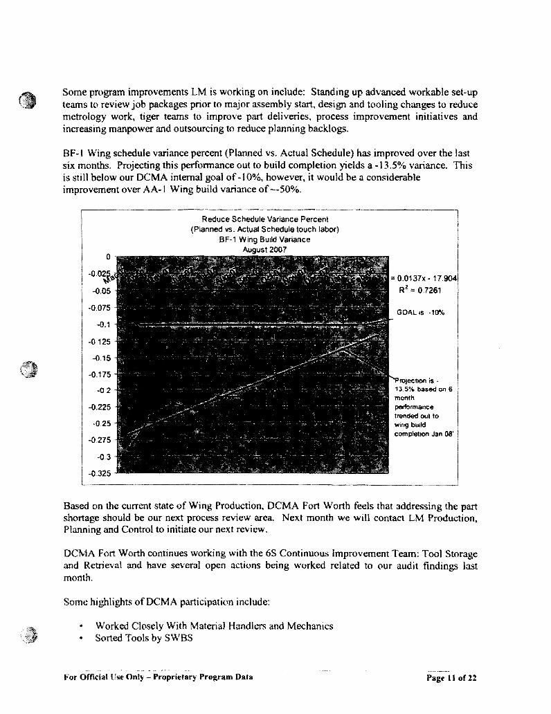
BF-l Wing schedule variance percent (Planned vs. Actual Schedule) has improved over the last six months. Projecting this perfonnance out to build completion yields a -13.5% variance. This is still below our DCMA internal goal of -10%. however, it would be a considerable improvement over AA-l Wing build variance of --50%.
Reduce Schedule Variance Percent (Planned vs. Actual Schedule touch labor)
BF-1 Wjng Build Variance
-0.
2007
=0.0137xR2 =0.7261
wing bUIld
completion Jan OS'
Based on the current state of Wing Production, DCMA Fort Worth feels that addressing the part shortage should be our next process review area. Next month we will contact LM Production, Planning and Control to initiate our next review.
DCMA Fort Worth continues working with the 6S Continuous Improvement Team: Tool Storage and Retrieval and have several open actions being worked related to our audit findings last month.
Some highlights ofDCMA participation include:
• Worked Closely With Material Handlers and Mechanics • Sorted Tools by SWBS
I'or Official Use Only - Proprietary Program Data Page I J of 22


Effective Quality Processes I Reduction in MRB Discrepancies-Based on the review ofcustomer metrics, audits were conducted by DCMA with our focus in the hole drilling process. We have created Process audit checklists and are continual1y updating them to meet our goal. Areas observed during audits consisted of the following- LM Employee Training, EWI/Blueprintl AEIlAEA data currency, engineering change implementation, FOD/tool control, housekeeping and controlled materials usage. As data is collected we can better detennine a plan of attack for recommendations that wilJ reduce the amount of MRB.
Contractor corrective measures are being reviewed and our focus on the multiple drilling issues continues to show as an area of concern. DCMA will continue audits focusing on the dri1Iing processes as well as the other high drivers in MRB.
Forward Fuselage Assembly (Risk -Moderate): No change of risk as Manual Hole Drill / Prep continues to be the top defect driver.
Wing Assembly (Risk - Moderate): No change of risk as Manual Hole DriH /Prep continues to be the top driver for defects in this area as well. Tool control is a very unstable process in the Wing area
Mate (Risk Moderate) No change of risk as defects tor hole issues and fastener installs continue to be an area needing attention.
Fhght Ops / Delivery (Risk - Moderate): 2AAI, Customer Concern (leA # 69008) Follow-up surveillance has revealed no additional areas of concern. DCMA has performed several follow-up audits to assess the adherence to written work instruction in the flight operations area (Run station 4). Having tound no further incidence of the concern referenced in ICA # 69008. We have given authorization to dose this concern but have informed LM that we will continue surveillance to insure that this process remains in control and progresses with added requirement.
~.,-
For Official Use Only - Proprietary Program Data Page 13 of 22

Engineering, EWI, and workmanship discipline issues continue to be the high drivers.
DCMA will continue to audit to ensure engineering changes are carefully controlled during implementation. Continued monitoring of contractor corrective measures are being undertaken to focusing on the multiple drilling issues. We are continuing audits focusing on the drilling processes being used. Contractor data is reviewed weekly and process audits are being scheduled in each area in attempt to influence MRB and to establish a DCMA observed trend as well as establishing documented surveillance strategy.
5.0 Vehicle Systems Electro-Hydrostatic Actuation System (EHAS) - SOF testing will start with the -8 Electronic Units (EU's) and end with the -to configuration. The -8 EU configurations will be used for BFt power-on activities. Ultimately, the -10 EU configurations will be used for STOVL B-1 first flight.
.;; working to a new specification to update functional SOF test procedures (120). LM has approved 59 functional SOF test procedures and 61 remain to be completed before the start of STOVL System SOF. Approval for a remaining quantity of SOF test procedures will be required to complete STOVL System SOF testing. Testing is in progress utilizing previously approved procedures.
The current EHAS system specification (Rev F) has 23 supplements. A Rev G is to be issued to consolidate Rev F and all current supplements.
The program plan is under pressure to meet LM remaining needs for:
• Software FQT completion by Dec 07 (slipped from Sept 07) • 8-1 system (wing and empennage) SOF completion by Dee 07 Feb 08 • System SOF completion by Dee 07 Feb 08 • -;OF completion by Dee 07 Mar 08
The above aggressive schedule is dependent on a timely solution of CTOL system Problem Reports (PRs) that have been pushed to STOVL. The number of EHA and EU CTOL PRs will not have a great impact/risk on the STOVL schedule.
LM Aero comment: LM has reacted strongly to the emerging situation at by putting an experienced, multidisciplinary RTG team in place at
This IS-person team is led by a proven Sr. Manager who is acting essentially a.... a co-Program Manager to the PM. Lockheed JSF executive management has also actively encouraged 10 assume more responsibilities as a partner to Lnd has put a manager in place at , well.
1as established a Risk Board. The team is working to identify all known risks that are being reported in all IPT areas. Efforts include the development of a comprehensive Risk Management strategy. Risk Management Tool selection is among the current discussion items.
For Official Use Only - Proprielary Program Oata Page 14 of 22

System Check-Out Procedures (SCOPs) Completion Progress - A total of 107 SCOPs remain to be completed prior to BF-I first flight (May 08). Current completion rate is approximately 46% behind MS5 schedule as of Sep 07.
Leading Edge Flap Actuation System (LEFAS) - ,hac; proposed design changes to LEFAS performance based specification (PBS) 2ZRZOOOIO Revision C to revise the temperature requirement to -77 OF to 248 OF. This change will require Safety of Flight regression testing and retrofitting of2AF and 2BF aircraft hardware.
Electrical Power System (EPS) - has completed AA-I return to tlight (RTF) activity with re-certification of the Inverter Converter Controller (ICC) and sub-system on 22 Aug 07. This included multiple interim software releases, extensive fault testing in System Integration Lab (SIL) at nd the Vehicle System Integration Facility (VSIF) at LM, failure and safety analyses, a thorough review of high voltage design rules. and support to other suppliers. Per LM direction, this effort was made priority # 1. and the impact to the remainder of the program is being assessed.
Following the PMR, 'eld a detailed schedule review on 18 Sept 07 to mitigate RTF impact to the CF-l alternate configuration of hardware. Key sequencing and hardware allocation initiatives were taken to pull back certification dates for the ICC. ESG and sub-system to support the vehicle manufacturing plans and provide hardware as early as possible to VSIF for EHAS integration risk reduction testing. Several actions remain open in order to meet this plan, and an impact ao;sessment of the schedule acceleration is under way.
HS finalized an enhancement to the ground fault logic that provides a more robust solution to short circuit conditions encountered on Flight 19. The solution is incorporated into Block 6 software which has been delivered to LM. This should eliminate the possibility of one ICC tripping because of fault return current from the other ICC. This solution also increases sampling time for critical fault parameters which prevents the possibility of nuisance tripping. Verification tests have been successfully completed in both the VSIF and SIL.
A humidity test failure is under investigation for the 5.4 kV A Nonlinear Inverter (NU). This has caused a delay in the SOF certification and hardware shipments to BF-I. A workaround plan is underway to provide a qualification unit to the aircraft for power-on pending completion of the failure resolution plan.
Power Thermal Management System On 21 Aug 07, the Integrated Test Stand (ITS) experienced a shut down while the PTMS was operating in cooling bleed mode. The ITS is currently in refurbishment due to damage sustained during testing. Due to the ITS system shut down, the developmental testing is now 40 days behind schedule. /ill re-scope their development activities. but WIll maintain the BF-l SOF start date of 26 Oct 07
. is confidence that the rotor was the root cause of the PTMS failure. They believe that the rotor contacted the stator and gradually wore the stator, the rotor's sleeve and the enclosing magnet' .. is redesigning the
or by introducing additional clearance between the rotor and stator .
._.. For Official Use Only Proprietary Program Data Page 15 of 22

Supplier Schedule - A total of 10 components remain to be delivered which are required for BF1 initial power-on schedule for 22 Oct 07. See attached document below for detailed list.
6.0 Mission Systems The following SW Productivity table provides the required and an estimate of the actual block 0.1 and 0.5 software productivity for each of the major software teams. This table shows results of SW Productivity calculation that uses cumulative hours since the over target baseline (OTB).
For Official lise Only - Proprietary Program Data Page 16 of 12


s.o Earned Value DCMA JSF - August 07 Data
Lockheed is now reporting to an Over Target Baseline of reported in the Cost Performance Report (CPR). The August 2007 cost summary is as tollows:
SAC LM £.\C CPR DC1\1:\ IEAC Performance Measurement
Baseline (PMB) Management Reserve
r--._~_-,(_M_R-!-)__._t--______ ~_...J.___ ~------!-----
Total: Table I - Budget Baseline and EAC Summaries
(a) Yellow
10%
5.3%
Primary Trip Wires
(a) System IndIcator: See EV Report (System Surveillance Section) (b) Baseline Indicators: A baseline assessment shows the contractors BAC and EAC to be optimistic. To complete the contract within the CBB, the contractor needs to be about 53 percent more efficient. The BAC has increased by 36% since the start up in Cot of 200 1. The cost growth is likely to increase due to inherent engineering risks in the first versions of STOVL and CV
For Official Use Only Proprietary Program Data Page 19 of22

air('r!>ft
Secondary Trip Wires
The Baseline Execution Index (BEl) metric is an Integrated Master Schedule (IMS) based metric that calculates the efficiency with which actual work has been accomplished when measured against the baseline. The BEl provides insight into the realism of program cost, resource, and schedule estimates. An index of 1.0 indicates the program is being completed as planned.
• Baseline Execution Index (BEl): Cumulative Tasks from October 2001 thru September 2007: Cum BEl = I) 3,851 Completed Tasksf126A46 Planned Tasks = 0.90 Monthly (September 2007) BEl = 1197 Completed Tasksll959 Planned Task = 0.61
• SPI= BCWP/BCWS' J.Q85
The Critical Path Length Index (CPU) indicates whether or not the program schedule can be completed on time. This is an Integrated Master Schedule (lMS) based metric that calculates the longest, continuous sequence of tasks through the network schedule from contract start to contract completion. An index of 1.0 indicates the program will finish on-time. CPU = (Critical PathBa~hne Duration + Float Duration) ; Critical Pathsasehne Ounltion
• CPU= (2990 + (377))12990 = .87 • CPI= BCWP/ACWP= '0.982 • CPIfTCPI= 0.98211.034=.947 • Contracts Mods - (BAC now)/originaJ BAC I% I= . .359
The DCMA Risk Rating for EVMS at the total program level is rated yellow - using the agreed to parameter of VAC (-6.04%). Compare this to the Lockheed's EAC and one can see a difference of over 5%. Similarly, the TCPk"c is ditlerent when using the OCMA IEAC versus the contractor's EAC:
TCPlocMA lEAC = 0.873 TCPhMEAC = 1.034
Cumulative to date SPI and CPl are at ,985 and .982 compared to .981 and .982 in the previous month. Cumulative SV% and CV% are -1.54% and - J .80%, compared to -1.33% and - J .79% in previous month and are also rated green.
The complete EV Report is attached:
For Official Use Only - Proprietary Program Data Page 20 of22

9.0 Process Reviews A process review of System Engineering Memorandum (SEM) -103 was conducted by DCMA Fort Worth. This SEM is a temporary modification to System Engineering Instruction, SE1-l 074 - JSF Aerospace Equipment Instruction, and replaces the first three paragraphs of that Instruction in its entirety. The Instruction establishes uniform requirements for ddining, preparing. implementing. and using JSF Aerospace Equipment Instructions (AEIs). They and are generated when Build-To-Packages (BTP) data is insutlicient or too complex to provide the user the needed instructions and details to accomplish an engineering requirement.
AEI's are fonnaHy released engineering documentation. As such they are used to provide system test requirements and procedures for maintaining, rigging and troubleshooting aircraft issues. They are also used as the source material for Planning and System Check-Out Procedure (SCOP) development. Once the aircraft has been delivered (00-250), the Joint-Services technical Document (JTD) must be utilized.
All AEls are required to be reviewed and approved by the AEI Review Group (ARG) prior to formal release. ARG membership consists of Subject Matter Experts (SMEs) of the various disciplines listed with in Para. 3.1.4 of SEM-l 03.
-~
For OfficialUst' Only - Proprietary Program Data Page 21 ofl!

--
which is maintained by the ARG Chairperson. No published list of current membership was available. The document review process and subsequent approval signatures of the ARG membership are managed virtua]]y through Product Data Management (POM) System to provide traceability. If contlicts occur, the ARG board is convened with the responsible Engineering IPT (AEI's owner) in attendance.
Current strategy is to revisit SEM-] 03 process to verify its formal incorporation into SEI-1074 has occurred within 6 months.
10.0 Appendix A EV Assessment Criteria Rating Criteria is based on the OCMA VAC% and when possible should include MR in the OCMA IEAC
Yellow - -I O%<V AC%<-5%
VAC%<-IO%.N/R- Not Rated or Not Reported
For Official Use Only - Proprietary Program Oata Page 22 or 22


![F-35 Lightning II Joint Strike Fighter (JSF) Program ...1].pdf · The F-35 Lightning II, Joint Strike Fighter (JSF) program is developing and building a family of next-generation](https://static.fdocuments.net/doc/165x107/60cd040fe95f0e2aa2026b23/f-35-lightning-ii-joint-strike-fighter-jsf-program-1pdf-the-f-35-lightning.jpg)