JOINT OPERATORS TECHNICAL SPECIFICATION OF GSM, UMTS …
47
Please E-Mail the Corporate Library for further information about this document DOCUMENT REFERENCE: EE/CDOC/4413 OWNED BY : Kin Wan ISSUE: 4.1 DATE: 13 th July 2017 EE CORPORATE LIBRARY THIS DOCUMENT WHEN PRINTED WILL BE DEEMED AS UNCONTROLLED Printed from: EDMS/WEBSITE Turning Information Into Knowledge © 2017 EE Limited FOR CORPORATE LIBRARY USE ONLY PUBLIC JOINT OPERATORS TECHNICAL SPECIFICATION OF GSM, UMTS & LTE INDOOR CELLULAR SYSTEM SCOPE This document defines the requirements of indoor cellular system for GSM, UMTS and LTE operation. It covers the design and test requirements, and the characteristics of the elements used in the system where the network performance is affected. It also defines the scope of work and the expected deliveries from the contractor during the different phases of a project. It is expected that the contractor will be responsible for the maintenance of the indoor cellular system, therefore a high level service level agreement is described. PURPOSE This document will be used by the neutral host contractor (NHC) for the design and implementation of indoor cellular systems for the GSM, UMTS and LTE operation.
Transcript of JOINT OPERATORS TECHNICAL SPECIFICATION OF GSM, UMTS …

Please E-Mail the Corporate Library for further information about this document
DOCUMENT REFERENCE: EE/CDOC/4413
OWNED BY : Kin Wan
ISSUE: 4.1
DATE: 13th July 2017
EE CORPORATE LIBRARY
THIS DOCUMENT WHEN PRINTED WILL BE DEEMED AS UNCONTROLLED Printed from: EDMS/WEBSITE
Turning Information Into Knowledge © 2017 EE Limited FOR CORPORATE LIBRARY USE ONLY
PUBLIC
JOINT OPERATORS TECHNICAL SPECIFICATION OF GSM, UMTS & LTE INDOOR CELLULAR SYSTEM
SCOPE
This document defines the requirements of indoor cellular system for GSM, UMTS and LTE operation. It covers the design and test requirements, and the characteristics of the elements used in the system where the network performance is affected.
It also defines the scope of work and the expected deliveries from the contractor during the different phases of a project.
It is expected that the contractor will be responsible for the maintenance of the indoor cellular system, therefore a high level service level agreement is described.
PURPOSE
This document will be used by the neutral host contractor (NHC) for the design and implementation of indoor cellular systems for the GSM, UMTS and LTE operation.

© 2017 EE PUBLIC
EE/CDOC/4413 Page 2 of 47 Issue: 4.1
DOCUMENT TABLE OF CONTENTS SCOPE ................................................................................................................................................ 1
PURPOSE ........................................................................................................................................... 1
1. INTRODUCTION ............................................................................................................................ 7
1.1 DOCUMENTATION STRUCTURE .......................................................................................... 7
1.2 QUALIFYING PROCESS .......................................................................................................... 8
2. TECHNICAL SPECIFICATION OF THE DAS .......................................................................... 8
2.1 GENERAL ................................................................................................................................... 8
2.2 DESIGN REQUIREMENT ASSUMPTIONS ............................................................................. 10
2.3 THE DAS .................................................................................................................................... 13
2.4 COVERAGE................................................................................................................................ 14
2.5 COVERAGE OVERLAP BETWEEN RADIATING ELEMENTS OF DAS ............................. 16
2.6 COVERAGE OVERLAP BETWEEN THE INDOOR CELL AND OUTDOOR CELLS ......... 17
2.7 CONTROLLED LEAKAGE AND HANDOVER ...................................................................... 17
2.8 OVERLOAD AND INTERMODULATION .............................................................................. 18
2.9 CO-SITING ................................................................................................................................. 19
2.10 HEALTH AND SAFETY ............................................................................................................ 19
2.11 PEFORMANCE CHARACTERISTICS OF DAS ELEMENTS ................................................. 21
2.12 BASE STATION EQUIPMENT INTERFACE B ....................................................................... 21
2.13 SUPERVISORY .......................................................................................................................... 22
2.14 SYSTEM AVAILABILITY ....................................................................................................... 22
3. SCOPE OF WORK .......................................................................................................................... 24
3.1 RESPONSIBILITIES .................................................................................................................. 25 3.1.1 NHC Responsibilities ....................................................................................................... 25 3.1.2 Participating CNO’s Responsibilities ............................................................................... 26
3.2 DOCUMENTATIONS ................................................................................................................ 26 3.2.1 Feasibility Report ............................................................................................................. 26 3.2.2 Design Document ............................................................................................................. 27 3.2.3 As Build Document .......................................................................................................... 28 3.2.4 Commissioning and System Acceptance Test Report ...................................................... 28 3.2.6 Concession Applications .................................................................................................. 29 3.2.7 Factory Acceptance Test Report ...................................................................................... 29 3.2.8 Test Methodology Report ................................................................................................. 29
4. SERVICE LEVEL AGREEMENT ................................................................................................. 30
5. DAS TESTINGS ............................................................................................................................... 30
5.1 TEST EQUIPMENT .................................................................................................................... 30
5.2 COMMISSIONING AND SYSTEM ACCEPTANCE TESTS ................................................... 30 5.2.1 VSWR, Noise Level and System Gain/Loss .................................................................... 31 5.2.2 Coverage .......................................................................................................................... 32 5.2.3 Coverage Overlap Between Antennas Of The Same DAS ............................................... 36

© 2017 EE PUBLIC
EE/CDOC/4413 Page 3 of 47 Issue: 4.1
5.2.4 Coverage Overlap Between Indoor and Outdoor Cells .................................................... 36 5.2.5 Controlled Leakage and Handover ................................................................................... 36 5.2.6 RF Exposure ..................................................................................................................... 36 5.2.7 Supervisory ...................................................................................................................... 37
5.3 BASE STATION INTEGRATION AND LIVE COVERAGE VALIDATION ......................... 37
APPENDIX A: LICENCED SPECTRUM OF THE UK CELLULAR OPERATORS ...................... 38
APPENDIX B: FACTORY TESTS: SUB-SYSTEMS AND SYSTEMS .......................................... 39
APPENDIX C: GUIDELINES ON THE GENERATION OF SURVEY ROUTES .......................... 40
APPENDIX D: CONCESSION TEMPLATE .................................................................................... 42
APPENDIX E: SYSTEM LINK BUDGET SUMMARY TEMPLATE EXAMPLE ......................... 43
APPENDIX F: CONVERTING CW TEST RSSI RESULTS INTO GSM RXLEV, UMTS CPICH
RSCP AND LTE RSRP ...................................................................................................................... 44
DOCUMENT HISTORY ........................................................................................................................ 47
ACKNOWLEDGEMENT
This document is created with inputs and contributions from the current UK 2G, 3G and 4G cellular operators EE, Three, Telefónica O2 and Vodafone.

© 2017 EE PUBLIC
EE/CDOC/4413 Page 4 of 47 Issue: 4.1
REFERENCES. 1. 3GPP TS 25.104, Technical Specification Group Radio Access Network; Base
Station (BS) radio transmission and reception (FDD) 2. 3GPP TS 25.101, Technical Specification Group Radio Access Network; User
Equipment (UE) radio transmission and reception (FDD) 3. 3GPP TS 45.005, Technical Specification Group GSM/EDGE Radio Access
Network; Radio Transmission and Reception 4. 3GPP TS 36.101, Evolved Universal Terrestrial Radio Access (E-UTRA); User
Equipment (UE) radio transmission and reception
5. 3GPP TS 36.104, Evolved Universal Terrestrial Radio Access (E-UTRA); Base Station (BS) radio transmission and reception
6. 3GPP TS 25.106, Technical Specification Group Radio Access Network; UTRA repeater radio transmission and reception
7. 3GPP TS 36.106, Evolved Universal Terrestrial Radio Access (E-UTRA); FDD repeater radio transmission and reception
8. ETSI Standards under the Radio Equipment Directive (RED) 2014/53/EU 9. International Commission on Non-Ionizing Radiation Protection (ICNIRP),
Guidelines for Limiting Exposure to Time Varying Electric, Magnetic and Electromagnetic Fields (Up to 300GHz), Vol 74, No. 4 April, 1998.
10. BSI EN 50383, Basic standard for the calculation and measurement of electromagnetic field strength and SAR related to human exposure from radio base stations and fixed terminal stations for wireless telecommunications system (110MHz – 40 GHz)
11. IEC62232, Determination of RF field strength and SAR in the vicinity of radiocommunication base stations for the purpose of evaluating human exposure, International Electrotechnical Commission, Edition 1.0, 2011-05.
12. IET Wiring Regulations 17th Edition (BS7671), Jan. 2008.
© 2017 EE PUBLIC
EE/CDOC/4413 Page 5 of 47 Issue: 4.1
ABBREVIATIONS
3GPP 3rd Generation Partnership Project BCCH Broadcast Control Channel ACI Adjacent Channel Interference ACIR Adjacent Channel Interference Ratio ACLR Adjacent Channel Leakage Ratio ACS Adjacent Channel Selectivity ADC Analog-to-digital converter C/N Carrier-to-Noise CNO Cellular Network Operator CPICH Common Pilot Channel CPRI Common Public Radio Interface CW Continuous Wave (i.e. constant power and amplitude) DAC Digital-to-analog converter DAS Distributed Antenna System dBi Decibels relative to the gain of an isotropic antenna dBm Decibels relative to a milliwatt DECT Digital Enhanced Cordless Telecommunications DIN Deutsches Institute for Normung (Germans Standards Institute) DL Downlink Eb/Io Energy per bit/total received signal Ec/Io Energy per chip/ total received signal EIRP Effective Isotropic Radiated Power EMF Electromagnetic Fields ER Exposure Ratio ESN Emergency Services Network ETSI European Telecommunications Standards Institute EVM Error Vector Magnitude FDD Frequency Division Duplex GSM Global System for Mobile Communication GSM-R GSM-Railway HOT Heads of Terms ICNIRP International Commission on Non-Ionizing Radiation Protection IEE Institution of Electrical Engineers LOI Location of Interest LTE Long Term Evolution LTE-R LTE for Railway-dedicated wireless communications network LTE-U LTE in unlicensed spectrum M&E Mechanical and Electrical MBSFN Multimedia Broadcast multicast service Single Frequency Network MCL Minimum Coupling Loss MIMO Multiple Input Multiple Output MT Mobile Terminal MuLTEFire LTE in licence exempt (unlicensed or shared) spectrum NB-IoT Narrowband-Internet of Things NDA Non-Disclosure Agreement NGR National Grid Reference NHC Neutral Host Contractor NMAS National Measurement Accreditation Service PCDE Peak Code Domain Error PMR Private Mobile Radio POI Point of Interconnect ppm Parts per million QAM Quadrature Amplitude Modulation QPSK Quadrature Phase-Shift Keying RBS Radio Base Station RE Resource Element RF Radio Frequency RFID Radio-Frequency Identification

© 2017 EE PUBLIC
EE/CDOC/4413 Page 6 of 47 Issue: 4.1
RI Radiating Infrastructure RS Reference Signal of LTE RSCP Received Signal Code Power RSRP Reference Signal Received Power SAR Specific Absorption Rate SAT System Acceptance Test SIMO Single Input Multiple Output SLA Service Level Agreement TDD Time Division Duplex TRX Transceiver UL Uplink UMTS Universal Mobile Telecommunications System UWB Ultra Wide Band VSWR Voltage Standing Wave Ratio WCDMA Wideband Code Division Multiple Access WLAN Wireless Local Area Network

© 2017 EE PUBLIC
EE/CDOC/4413 Page 7 of 47 Issue: 4.1
1. INTRODUCTION
Riding on the success of the 2G (GSM) & 3G (UMTS) joint operator neutral host projects in the UK, the 2G and 3G cellular network operators EE, Three, Telefonica O2 and Vodafone agree to continue the scheme for the 4G (LTE) networks. This document forms the baseline for the existing indoor system upgrade and the new deployment covering the requirements of both GSM, UMTS and LTE operations for the frequency bands given in Appendix A.
This document specifies the requirements of indoor cellular system for the 2G (GSM), 3G (UMTS) and 4G (LTE) operations of which the Cellular Network Operators (CNO) subscribe. The system will be designed, installed and tested by a Neutral Host Contractor (NHC) who has the full turn-key responsibility for delivering such system meeting the requirements defined in this document. The NHC can be either an independent third party or one of the CNO.
The indoor cellular system can take the form of a single radiating element or distributed radiating elements which can use omni antennas, sector antennas, radiating cables or a combination of both together with RF components and sub-systems. For convenience, such cellular system referred in this document is called distributed antenna system (DAS).
The technical requirements for both 2G, 3G and 4G operations are described in section 2. The coverage requirements, the system performance and the components characteristics are specified in details.
Section 3 defines the scope of work with which the NHC will provide.
It is expected that the NHC will be responsible for the maintenance of the DAS. Section 4 describes a high level Service Level Agreement (SLA) which will be negotiated under the commercial agreement with each individual CNO.
A DAS is only acceptable into operation when the NHC verifies and demonstrates to the CNO that the specifications defined in section 2 are met. Section 5 describes the system acceptance test requirements.
1.1 DOCUMENTATION STRUCTURE
The document is made up of sections dealing with different aspect of the 2G, 3G and 4G DAS. Each of the requirements is marked as Q, I, R or M defining the necessity. To qualify as a NHC, the Tender is required to answer the questions, requirements and mandatory requirements.
For the purpose of this document, NHC is used in the document for the successful Tender.
Question Q is normally raised to get information from the supplier aiming for a better understanding of the issue.
Information I is supporting information for the NHC to design the DAS.
Requirement R is raised when the performance of the DAS is required to fulfil the mobile cellular operation. Full details of compliance will be useful in supporting our evaluation. If

© 2017 EE PUBLIC
EE/CDOC/4413 Page 8 of 47 Issue: 4.1
the requirement cannot be fulfilled, the Tender should provide alternative solution and explain the effects of non-compliance.
Mandatory requirement M is a critical requirement for which Tender shall answer with a “Comply” or “Non-comply”. Details shall be provided where possible to support the evaluation.
1.2 QUALIFYING PROCESS
The Tender shall submit a soft copy of response and any relevant information in MS Word, Power Point, Excel, Map Info, AutoCAD, etc. to each CNO for reviewing and making a decision on the suitability of the Tender to be a NHC. The Tender must response in full to the requirements. Where compliance is not possible, detailed explanation and alternatives shall be provided.
2. TECHNICAL SPECIFICATION OF THE DAS
2.1 GENERAL
1. R The NHC shall engage the CNO during each stage of a project.
2. M The DAS shall be capable of supporting radio signals of GSM, WCDMA and LTE technologies. Where the DAS incorporates other users such as the emergency services, public and private WLAN, in particular the non-public area outside the common interest of CNO, i.e. ESN, the performance specification defined in this document and the design of the DAS shall not be compromised. However, such additional services should be contributing to the DAS CAPEX and OPEX cost.
3. M The DAS shall be with the provision of the capacity handling according to the expected traffic and footfall.
4. M The DAS shall cover the frequency bands given in Appendix A.
5. M The proposed DAS must be the most cost effective solution utilising the full capability of the CNO’s equipment. Details of the equipment are provided in separate document.
6. R The requirements of the DAS defined in this document are only applied to the general public accessible area. If non-public area is required by the site owner and/or a third party or a specific individual CNO, it shall be covered separately between the site owner and the party of interest.
7. M Where a location already has a DAS installed for the 2G and/or 3G operation, the NHC must carry out an assessment of the impact of upgrading the existing system for supporting all GSM, UMTS and LTE technologies. This is considered to be generally more cost effective. If this is not possible, a report on the shortcomings and a comparison of costs and performance between a new DAS and an upgrade to a sub-standard DAS shall be given in the design document.
8. M The DAS shall be of modular construction so that it can be easily expanded and upgraded for capacity reason by way of sectorisation into additional DAS zones,

© 2017 EE PUBLIC
EE/CDOC/4413 Page 9 of 47 Issue: 4.1
for example, without significantly compromising the existing performance, and offers options for individual operator mapping the capacity and base station sectors to the DAS zones.
9. M The upgrade shall minimise the disruption to the current operations.
10. M Although it is not essential that the 2G, 3G and 4G signals of a CNO shall be carried on the same sub-system, it is mandatory that the traffic of the same frequency band of the associated CNO shall be carried on the same sub-system.
11. R This document defines the technical specifications for a DAS supporting the operation of
• GSM at 900MHz & 1800MHz bands, • UMTS at 900MHz, 1800MHz & 2100MHz bands and • LTE at 800MHz, 900MHz, 1800MHz, 2100MHz & 2600MHz bands • but excluding the GSM in the DECT guard band. • However, all passive components must be wide band covering at least both
GSM, UMTS and LTE bands as given in Appendix-A except specific band selective units for the purpose of channelisation and filtering.
• Wherever possible, the passive components should also cover 380-470MHz, 694-790MHz, 1472-1492MHz, 2310-2390MHz and 3400-3800MHz.
12. I In terms of LTE, the baseline requirement is referred to the MIMO DAS. Where a SISO DAS is proposed, the NHC should provide the justification and advise the upgrade path of the DAS for accommodating the MIMO operation in future, and also provide the conceptual design and the indicative cost of the DAS with the MIMO capability. The requirements defined in here are not specifically dictated the indoor solution to the passive/active MIMO or SISO DAS. Each location of interest and the solution will be assessed according to the figure of merits and will be agreed between the NHC and CNO
13. M The DAS shall be designed to operate with base station and mobile terminal meeting the 3GPP and ETSI standards [ref. 1-5]. Additionally, the DAS shall conform to all the current regulations, rules and the operation conditions imposed on CNOs by the UK Government and meet the 3GPP & ETSI Standards where appropriate i.e. [ref. 6, 7 & 8].
14. M When either 2G, 3G or 4G is added to an existing system, it must be ensured that the systems and operations of both the 2G, 3G and 4G are compliant with the ETSI recommendations.
15. R The DAS shall be used in indoor and confined space environments such as, but not limited to, tunnel, shopping centres, conference and exhibition halls etc.

© 2017 EE PUBLIC
EE/CDOC/4413 Page 10 of 47 Issue: 4.1
2.2 DESIGN REQUIREMENT ASSUMPTIONS
16. R Where the DAS is used for in-building, road tunnel or non-high speed train tunnel, the propagation model and performance requirements specified in TS25.104 Case 1, Case 3 or Case 4 for a mobile terminal travelling at a speed up to 3km/hr, 120km/hr or 250km/hr respectively shall be used, or the highest mobile terminal travelling speed confined by the venue with an added 20% margin in the design for the purpose of call handover.
17. I Each of the CNOs shall provide the NHC with a specification pack detailing the mechanical, electrical and RF interface specifications of the base station equipment. This will be provided under separate cover and under the condition of Non-Disclosure Agreement (NDA) with the NHC in order to comply with the confidentiality agreement between the CNO and their equipment vendors.
18. R Where information is not given by the CNO, the NHC can assume
• the 2G, 3G and 4G base station receiver noise figure of 4dB, • Mobile terminal maximum transmit power of 30dBm, 21dBm and 23dBm
for GSM, UMTS and LTE respectively, • Mobile terminal minimum transmit power of 5dBm, 0dBm, -50dBm and -
40dBm for GSM900, GSM1800, UMTS and LTE respectively, • the dedicated indoor system should provide at least a dominant coverage of
6dB over 95% of the coverage target area against the coverage provided by the external outdoor cell sites of any adjacent cellular networks,
• the dedicated indoor system delivers CPICH Ec/Io >= -8dB with reference to the UMTS cells of 20% loading (10% CPICH and 10% control signalling)
• a carrier-to-noise (C/N) ratio of 12dB for GSM voice calls in uplink and downlink, and
• 10% downlink RF composite power per UMTS operating channel assigned to Common Pilot Channel (CPICH)
• Reference Signal (RS) power of LTE may usually be with 3dB boosting as shown in table 1. Although the RS may be with 3dB power booster, the average sub-carrier power of LTE will still remain as
PFL – 10 x Log10(Nsc) ,
where PFL is referred to the full load channel carrier power and Nsc is the number of LTE sub-carriers in a given LTE channel bandwidth. There may be some special cases that an individual CNO may implement a power booster on RS power different from 3dB and NHC will be specifically advised by the individual CNO.

© 2017 EE PUBLIC
EE/CDOC/4413 Page 11 of 47 Issue: 4.1
Table 1: Reference Signal & sub-carrier power of LTE.
19. R With reference to the typical macro base station, the following output level can be assumed, otherwise the lowest level and the highest level given in the CNO’s standard pack shall be used for coverage design and power handling design respectively.
Base station type
Base station nominal output power per carrier
Power handling design per carrier (thermal
consideration) 2G base station 43dBm 46dBm 3G base station 33dBm (CPICH), 43dBm (full
load) 46dBm
4G base station (non-MBSFN transmission)
43dBm per transmission channel
46dBm per transmission channel
Table 2: Base station output power.
There may be some specific cases that a different power class of base station, i.e. micro, pico, small cell, etc., may be used and NHC will be advised accordingly in the pre-feasibility/ feasibility phase of the project.
Where an active DAS is proposed, the NHC shall provide a means to adjust the gains and losses of the active DAS per individual CNO per band for optimising the downlink and uplink of the DAS independently. Although it is the responsibility of the NHC to provide appropriate safe guard protecting the DAS from overloading, in particular the downlink, the NHC is required to provide the evidence to show the budget allocation between CNO in terms of the RF power, optical and/or digital bits on the active sub-systems of the DAS.
(*) For the system design, with reference to the downlink coverage requirements, it is referred to the linear average over the power contributions of the Resource Elements (the OFDM symbols) carrying reference symbols only instead of the full load power, i.e. the downlink coverage is expressed as RSRP.
20. R For the purpose of coverage overlapping design including the tunnel portals to and from the CNO macro networks, the maximum and minimum handover time is 10 and 4 seconds respectively.
5 10 15 20 5 10 15 20
300 600 900 1200 300 600 900 1200
5 37.0 15.2 12.2 10.5 9.2 12.2 9.2 7.5 6.2
10 40.0 18.2 15.2 13.5 12.2 15.2 12.2 10.5 9.2
15 41.8 20.0 17.0 15.3 14.0 17.0 14.0 12.3 11.0
20 43.0 21.2 18.2 16.5 15.2 18.2 15.2 13.5 12.2
30 44.8 23.0 20.0 18.3 17.0 20.0 17.0 15.3 14.0
40 46.0 24.2 21.2 19.5 18.2 21.2 18.2 16.5 15.2
LTE channel bandwidth [MHz]
number of LTE sub-carriers within
a given channel bandwidh
average power of each sub-carrier
[dBm]
LTE channel bandwidth [MHz]
number of LTE sub-carriers within
a given channel bandwidh
carrier
power
[W]
carrier
power
[dBm]
Transmit Reference Signal power
with 3dB power booster [dBm]

© 2017 EE PUBLIC
EE/CDOC/4413 Page 12 of 47 Issue: 4.1
21. I The following link budget assumptions can be used for the purpose of the system design:
• body loss: 5dB • car penetration loss: 7dB • train loss: case by case basis

© 2017 EE PUBLIC
EE/CDOC/4413 Page 13 of 47 Issue: 4.1
2.3 THE DAS
22. R The DAS will comprise of a number of network sub-systems and interfaces as shown in figure 1.
Figure 1: Schematic diagram of DAS system
Where MT is the mobile terminal, RI is the Radiating Infrastructure, RBS is the Radio Base station, NTE is the Network Transmission Equipment for connecting the
traffic to core network, CNO PSU is the CNO’s power supplier unit(s) for RBS and NTE,
A is the air-interface, B is the Point of Interconnect (POI) with the CNO’s equipment, C is the interface with the external transmission connections, and D is the interface with the power supply.
23. R All the components within the shaded enclosure of figure 1 including any cables connected to the CNO’s equipment are the responsibility of the NHC.
24. R The DAS is made up of RI and the interfaces A and B.
25. R Depending on the size of the Location of Interest (LOI) and the complexity of the design for reason of technicality and practicality, the RI can be made up of:-
(a) passive elements such as filters, couplers, antennas, feeders and/or radiating cables
(b) active elements such as ADC, DAC, CPRI, IP router/switch, radio over fibre sub-system and amplifier
(c) a mixture of (a) and/or (b) with or without in-line amplifier(s).
26. I For the DAS with active elements, two types are referred in this document:
• wideband active DAS: all downlink and uplink active elements covering the whole mobile cellular’s downlink and uplink operating bands respectively per GSM and/or and/or UMTS and/or LTE technology, and
MT A RI B C
Power supply
D D
RBS NTE
CNO PSU
© 2017 EE PUBLIC
EE/CDOC/4413 Page 14 of 47 Issue: 4.1
• narrow band active DAS: some active elements only covering the sub-bands of the GSM, UMTS and LTE operating bands with respect to the appropriate downlink and uplink directions.
27. R Where active DAS is proposed, the end-to-end system uplink loss shall be less than the end-to-end system downlink loss in general. Subject to the detailed analysis with justification approved by CNO, the end-to-end system uplink loss can be equal to or higher than the end-to-end system downlink loss.
28. M The NHC is responsible for the DAS, the Power Supply and a safe interface (D) so that the CNO can connect their equipment to the power supply. The NHC is also responsible for the provision of a proper accommodation for the installation of the CNO’s equipment, and provision of space for the installation of external transmission equipment (C) such as leased circuit or external microwave radio.
29. R Where the RI requires power for its operation, the NHC is entirely responsible for the provision and installation of the required power supply.
2.4 COVERAGE
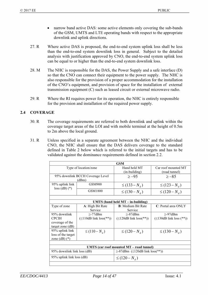
30. R The coverage requirements are referred to both downlink and uplink within the coverage target areas of the LOI and with mobile terminal at the height of 0.5m to 2m above the local ground.
31. R Unless specified in a separate agreement between the NHC and the individual CNO, the NHC shall ensure that the DAS delivers coverage to the standard defined in Table 2 below which is referred to the initial targets and has to be validated against the dominance requirements defined in section 2.2.
GSM Type of location/zone Hand held MT
(in-building) Car roof mounted MT
(road tunnel) 95% downlink BCCH Coverage Level
(dBm) 95− 85−
95% uplink link loss (dB) (*)
GSM900 )133( dN− )123( dN− GSM1800 )130( dN− )120( dN−
UMTS (hand held MT – in-building)
Type of zone A: High Bit Rate Service
B: Medium Bit Rate Service
C: Portal area ONLY
95% downlink CPCIH coverage of the target zone (dB)
≥-77dBm (≤110dB link loss(**))
≥-87dBm (≤120dB link loss(**))
≥-97dBm (≤130dB link loss (**))
95% uplink link loss of the target zone (dB) (*)
)110( dN− )120( dN− )130( dN−
UMTS (car roof mounted MT – road tunnel)
95% downlink link loss (dB) ≥-87dBm (≤120dB link loss(**))
95% uplink link loss (dB) )120( dN−

© 2017 EE PUBLIC
EE/CDOC/4413 Page 15 of 47 Issue: 4.1
LTE (hand held MT – in-building) Type of zone A: High data rate
service B: Medium data rate service
C: Portal area ONLY
95% downlink reference coverage (reference signal received power, RSRP) (***)
>-95dBm >-105dBm >-110dBm
95% uplink loss (*)
)110( dN− )120( dN− )125( dN−
Typical area Zone A: low mobility and high density mobile Zone B: medium/high mobility and low/medium density mobile Zone C: portal area ONLY
Example (not exhaustive list. Each venue MUST be analysed and assessed on a case by case basis.)
Zone A: - Airport: lounge, restaurant/bar, shopping area, departure gate etc. - Shopping Centre: food court, restaurant/bar, seating area, etc. - sport venue: seating area, hospitality/concourse area - hotel/conference centre/exhibition centre: conference/meeting area,
public break-out area, restaurant/bar Zone B:
- Airport: arrival gate, transit area etc. - Shopping Centre: back of the shop where public can access - sport venue: public transit area other than the concourse area
mentioned in zone A - hotel: any other areas subject to a separate agreement between CNO
and NHC Zone C:
- any transition from the areas served by the dedicated indoor system to the adjacent cellular network which can be another indoor cell or the outdoor cellular network
Note:
- corporate coverage is likely to be designed as the requirements for zone A but it will be subject to a separate agreement between an individual CNO and NHC
Table 2: Coverage specification.
(*) where Nd in dB is the increase of receive noise floor at base station receiver due to the uplink noise of the DAS at the relevant band, and the base station noise floor is assumed to be -170dBm/Hz at the receive band. Illustration of the base station noise floor degradation calculation:
- Base station receive noise floor = -170dBm/Hz (or 10-17mW/Hz, noise figure = 4dB) - Uplink noise of DAS at base station interface = -165dBm/Hz (or 3.2x10⁻¹⁷mW/Hz) - Composite uplink noise due to DAS and base station -163.8dBm/Hz (or 4.2x10⁻¹⁷mW/Hz) - Increase of receive noise floor at base station, Nd, 6.2dB = (-163.8 – (-170))dB
(**) The downlink link loss of UMTS stated in table 2 is with reference to the typical CPICH transmit power of 33dBm for the case of the typical full load downlink carrier of 43dBm. Where a different power class of base station is used an appropriate offset shall be applied to the requirements.

© 2017 EE PUBLIC
EE/CDOC/4413 Page 16 of 47 Issue: 4.1
(***) RSRP for each cell is the linear average over the power contributions of the Resource Elements that carry cell-specific Reference Signals within the considered measurement frequency bandwidth. It can therefore only be referred to and measured in the OFDM symbols carrying reference symbols.
32. R The NHC shall propose and define the zone types in each design for the CNO to comment and agree.
33. R The link loss defined in table 2 is the end-to-end loss between the mobile terminal (the interface A of figure 1) and the last connection of the individual CNO’s base station (the interface B of figure 1).
34. R The NHC must make allowances for the floor variations, fading, clutter loss and environment etc. in the design in order to ensure the required percentage of the agreed areas of the LOI covered. If the DAS is for train tunnel, the NHC shall make provision in the design of train carriage losses.
35. R For the 3G and 4G, busy traffic zones such as Zone A do not necessarily mean that more antennas will be required. The placement of the antennas (including radiating cable if appropriate) shall take into consideration that the demand of higher data rate is most likely at places where the 3G and/or 4G mobile terminal can be stationary or quasi-stationary such as lounges, restaurants and cafés etc.
2.5 COVERAGE OVERLAP BETWEEN RADIATING ELEMENTS OF DAS
36. R The NHC shall design the coverage delivered by each antenna of the DAS has adequate overlap without discontinuity of service in the coverage area.
37. R This requirement for coverage overlap also applies to boundaries where sectorisation is most likely to be employed when capacity expansion is required. Based on the local knowledge of the location, the NHC shall highlight these boundaries within the DAS.
38. R Where multiple cells are proposed, the cell boundary shall have adequate coverage overlap enabling a mobile terminal to complete a handover within the handover time defined above.
39. R Any sectorisation of the DAS shall avoid the high traffic area in order to minimise the handover between them. The design should provide an indication of the number of users per DAS zone.
40. I CNO considers 2000 active users per DAS zone are reasonable assumption at this stage.
41. R The coverage overlapping areas provided by any two adjacent indoor cells of the DAS shall be less than 15% with reference to
• the coverage target area of that particular two indoor cells and also
• 3dB link loss window as shown in an example of figure 2 below.

© 2017 EE PUBLIC
EE/CDOC/4413 Page 17 of 47 Issue: 4.1
42. R No area of the LOI shall be simultaneously served by more than 3 indoor cells.
Coverage area of Cell A i.e. RSPA > RSPB + 3
Coverage area of Cell B i.e. RSPB > RSPA + 3
AreaA: area where RSPA > (RSPB + 3dB)AreaB: area where RSPB > (RSPA + 3dB)AreaC: area where |RSPA - RSPB|≤ 3dB)
where RSP stands for received signal power of piloti.e. BCCH RxLev of 2G, CPICH RSCP of 3G, RS RSRP of 4G
𝐴𝑟𝑒𝑎𝐶𝐴𝑟𝑒𝑎𝐴 + 𝐴𝑟𝑒𝑎𝐵 + 𝐴𝑟𝑒𝑎𝐶
≤ 15%
Figure 2: Coverage overlapping illustration of any two adjacent indoor cells.
2.6 COVERAGE OVERLAP BETWEEN THE INDOOR CELL AND OUTDOOR CELLS
43. R The NHC shall position some of the antennas of the DAS so that the portal shall be adequately covered without breaching the controlled leakage requirements defined in section 2.7. This shall ensure a proper handover in both directions between the indoor cell and the external cells which are defined as the cell(s) not under the responsibility of the NHC.
44. R The handover between the outdoor cells and the indoor cells may be of inter-frequency nature, i.e. hard handover which will take longer time to complete. Therefore, the coverage overlapping distance between the outdoor cell and the indoor cells at the portals shall ensure continuous voice call of a mobile terminal at the speed as defined in section 2.2
45. R For reason of avoiding uncertainty and conflict of responsibility, it is a preference where possible that all handover occur inside the LOI except the road tunnel and rail tunnel in where the handover may be taken place outside. The exceptional cases of tunnel are not the exhausted examples, and each LOI should be assessed accordingly.
2.7 CONTROLLED LEAKAGE AND HANDOVER
46. R The distance of the controlled leakage from the LOI is with reference to a mobile terminal at the speed as defined in section 2.2 and also takes the maximum and minimum handover time into account.
47. R As shown in figure 3, the distance of the signal overspill from any portals of the LOI shall be less than the double of the handover distance for the uplink link loss greater than 142dB. Where the DAS is designed for the non-high speed rail or

© 2017 EE PUBLIC
EE/CDOC/4413 Page 18 of 47 Issue: 4.1
road tunnel, the controlled signal overspill shall be confined along the rail track or road route outside the tunnel for a proper handover between the tunnel cells and the CNO outdoor cells.
48. R With the exception of the portals of the LOI and as shown in figure 3, the distance of the signal overspill shall be less than the handover distance for the uplink link loss greater than 142dB.
Figure 3: Illustration of the controlled leakage and handover distances.
2.8 OVERLOAD AND INTERMODULATION
49. R The selection and the placement of the radiating elements of the DAS shall not cause overloading, blocking and de-sensitisation to the mobile terminal in the downlink direction, and the CNO’s base station and any active units of the DAS in the uplink direction due to the presence of a mobile terminal transmitting at full power within the coverage range of the radiating element, especially in close proximity to the radiating element concerned.
50. R The minimum coupling loss (MCL) is referred to the location at where the minimum path loss between the mobile terminal and the DAS will occur, and the mobile terminal will receive the maximum downlink signal and the CNO’s base station will receive the maximum uplink signal.
51. R The NHC shall carry out an assessment for each design, state the MCL which will be achieved and ensure the downlink and uplink overload, blocking and de-sensitisation will not occur. The maximum downlink signals at a 2G, 3G and 4G mobile terminal shall be less than -40dBm, -25dBm and -25dBm per cellular channel respectively, and the maximum uplink signal level per cellular channel at the CNO’s 2G, 3G and 4G base stations shall be less than -35dBm, -52dBm
portal
Handover distance
D
Signal overspill distance ≤ 2D with UL link loss >142dB from any portals
Signal overspill distance ≤ D with UL link loss >142dB from any non-portals
Signal overspill distance ≤ D with UL link loss >142dB from any non-portals
Signal overspill distance ≤ D with UL link loss >142dB from any non-portals
LOI

© 2017 EE PUBLIC
EE/CDOC/4413 Page 19 of 47 Issue: 4.1
and -50dBm respectively. Consideration of alternative antenna types and/or the antenna locations and the overall system design may be necessary to achieve the requirements.
52. R The NHC shall endeavour to position the radiating element such that a far mobile terminal at the edge of an antenna coverage area will not be affected by a near and uncoordinated mobile terminal at the MCL position of the same radiating element, transmitting 30dBm, 21dBm and 23dBm at the GSM, UMTS and LTE frequency band respectively. The uncoordinated mobile terminal is due to the CNO who does not subscribe to the DAS.
53. R In the absence of 3GPP specification specifically for the DAS, the design of the DAS shall ensure that the total intermodulation and spurii generated by the DAS and the CNO’s base station(s) under full load conditions shall still comply with the appropriate specifications recommended by the 3GPP Standards i.e. [Ref. 1,3, 5, 6 and 7].
54. R When connected to all the base station equipment permitted by the design, the DAS must meet the same requirements as specified for a single GSM, UMTS and LTE base station.
2.9 CO-SITING
55. R The NHC shall ensure that the system is designed, either by suitable filtering or other means, to prevent any significant mutual interference between any 2G, 3G and 4G channels of the CNO and other telecommunication installations in the premises at the time of design and installation. This includes but not limited to the presence of GSM-R, PMR, wireless local access network (WLAN), ultra wide band (UWB) device, RFID, LTE-U, MuLTEFire, LTE-R etc.
56. R The effective degradation to the UL and DL receive sensitivity due to the effect of co-siting shall not be more than 0.1dB over the additional RF branching loss essential for co-siting implementation. This is applied to where the GSM, UMTS and LTE signals are distributed over different or same signal distribution layers with different or same radiating elements.
2.10 HEALTH AND SAFETY
57. R In terms of the DAS design related to human exposure to electromagnetic fields (EMF), appropriate exposure limits defined by ICNIRP standard [ref. 9] according to the implementation conditions shall be used.
58. R The NHC shall take the full responsibility for the risk assessment in where the public or occupational EMF limit is applied to each radiating element. The EMF exposure limit for the general public shall be used in any public accessible locations.
59. R Maximum radiated power from any single radiating element shall not expose anyone to an EMF level which exceed the current guidelines in the ICNIRP standard. This shall take into account of the maximum number of carriers (2G, 3G and 4G as appropriate) to be carried by the DAS concerned.

© 2017 EE PUBLIC
EE/CDOC/4413 Page 20 of 47 Issue: 4.1
• Where the radiating element will be installed at the general public accessible location and can be reached without any aids i.e. stand or ladder, the Specific Absorption Rate (SAR) threshold, i.e. 2W/kg within 10g volume, for the general public is applied.
• Where the radiating element can only be reached with aids i.e. stand or ladder, the SAR threshold, i.e. 10W/kg within 10g volume, for the occupational can be used.
60. R Any SAR thresholds such as the maximum input power to the radiating element established and used in the design shall be based upon the SAR based tests of the radiating elements according to the appropriate methodology as stated in Ref. 10 and also Ref. 11 which will be adopted in the near future.
61. R The total exposure ratio (TER), as defined in eq (1), of any radiating elements to be deployed at any public or occupationally accessible area shall be less than or equal to 1, and is given by
=n
i iSAR
ix
P
TTER
,
, eq (1)
where
• Tx,i represents the composite RF power (stated in Watts) of a given band fed into a radiating element of the DAS. At present, the operating bands are referred to the mobile cellular band of 800MHz, 900MHz, 1800MHz, 2100MHz and 2600MHz. The other bands will need to be taken into account in the future.
• PSAR,i, PSAR,j, … and PSAR,n represent the maximum powers (stated in Watts) at CNO’s bands that can be fed into a radiating element and whilst ensuring that the resulting exposure levels are less than the limits stated by ICNIRP. Again, the other bands will need to be taken into account in the future. See [8] for further details on occupational and public exposure limits.
62. M The NHC shall issue a ICNIRP compliance statement for every design of the indoor cellular system and indicates which radiating elements are compliant with the public and occupational exposure limits.
63. M The equipment room shall be designed to meet all the relevant building regulations in particular in areas concerning health and safety.
64. M All the electrical installations shall follow the IET wiring guidelines [Ref 12].
65. M With the exception of the CNO equipment, the NHC is wholly responsible for the health and safety of the DAS which includes all of the components within the shaded enclosure of Figure 1.

© 2017 EE PUBLIC
EE/CDOC/4413 Page 21 of 47 Issue: 4.1
2.11 PEFORMANCE CHARACTERISTICS OF DAS ELEMENTS
66. M Where an active or a hybrid system is used for the DAS, all the active equipment must be type approved to the appropriate 3GPP recommendations.
67. M The spectral emission from the DAS together with the 2G, 3G and/or 4G base station(s) shall comply with the 3GPP standards offset according to the output power difference between a base station and the remote unit of an active DAS, i.e. the spectral mask in the specification shall be maintained. In addition, as specifically required by Ofcom, any out-of-band emission spuii, between 2500MHz-2615MHz and also 2700MHz- 3100MHz, radiated by any radiating elements of the DAS shall be <-45dBm/MHz.
68. R The overall gain flatness of the DAS over the whole CNO’s licensed bands per technology shall be less than 3dB. In addition, within each CNO’s 3G & 4G 5MHz band and 2G 200kHz channel, the gain flatness of the DAS shall be less than 1dB.
69. R The maximum single trip propagation delay caused by the DAS and air interface shall not be more than 66µs due to the cell range limitation of some vendor’s base stations. The differential delays of 2G signals received by a mobile terminal from the same source shall be less than 16µs because of equalizer limitation of the mobile terminal. The group delay difference shall be no more than 30ns per 3G channel. The delay spread of 4G signals received by a mobile terminal from the same source shall be less than 5.2µs because of the LTE normal cyclic prefix.
70. R The Error Vector Magnitude (EVM) introduced by the DAS shall be
• less than 6% for both 2G and 3G operation,
• less than 17.5%, 12.5%, 8% and 3.5% for all RE allocated for shared channels (PDSCH) with the modulation schemes of QPSK, 16QAM, 64QAM and 256QAM of 4G operations respectively, and
• less than 17.5% for all RE allocated for NB-PDSCH of NB-IoT with QPSK.
71. R The DAS shall not degrade the phase noise performance of the UL and DL signals. If frequency conversion is involved in the DAS, the local oscillator shall use a single common reference with a frequency stability conforming to 3GPP recommendations. The frequency deviation of the output signal with respect to the input signal shall be no more than +/- 0.01ppm.
2.12 BASE STATION EQUIPMENT INTERFACE B
72. R The DAS shall provide separate 2G, 3G and 4G interface ports for each CNO.
73. R The preferred operation mode is duplex unless specified differently by individual CNO.
74. R The interface impedance shall be 50 ohm with a VSWR of less than 1.4:1 over the whole 2G, 3G and 4G band detailed in Appendix A.
© 2017 EE PUBLIC
EE/CDOC/4413 Page 22 of 47 Issue: 4.1
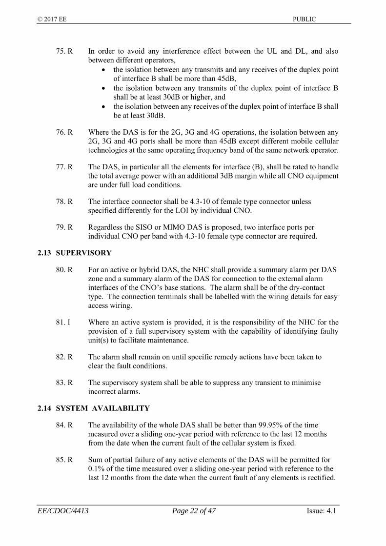
75. R In order to avoid any interference effect between the UL and DL, and also between different operators,
• the isolation between any transmits and any receives of the duplex point of interface B shall be more than 45dB,
• the isolation between any transmits of the duplex point of interface B shall be at least 30dB or higher, and
• the isolation between any receives of the duplex point of interface B shall be at least 30dB.
76. R Where the DAS is for the 2G, 3G and 4G operations, the isolation between any 2G, 3G and 4G ports shall be more than 45dB except different mobile cellular technologies at the same operating frequency band of the same network operator.
77. R The DAS, in particular all the elements for interface (B), shall be rated to handle the total average power with an additional 3dB margin while all CNO equipment are under full load conditions.
78. R The interface connector shall be 4.3-10 of female type connector unless specified differently for the LOI by individual CNO.
79. R Regardless the SISO or MIMO DAS is proposed, two interface ports per individual CNO per band with 4.3-10 female type connector are required.
2.13 SUPERVISORY
80. R For an active or hybrid DAS, the NHC shall provide a summary alarm per DAS zone and a summary alarm of the DAS for connection to the external alarm interfaces of the CNO’s base stations. The alarm shall be of the dry-contact type. The connection terminals shall be labelled with the wiring details for easy access wiring.
81. I Where an active system is provided, it is the responsibility of the NHC for the provision of a full supervisory system with the capability of identifying faulty unit(s) to facilitate maintenance.
82. R The alarm shall remain on until specific remedy actions have been taken to clear the fault conditions.
83. R The supervisory system shall be able to suppress any transient to minimise incorrect alarms.
2.14 SYSTEM AVAILABILITY
84. R The availability of the whole DAS shall be better than 99.95% of the time measured over a sliding one-year period with reference to the last 12 months from the date when the current fault of the cellular system is fixed.
85. R Sum of partial failure of any active elements of the DAS will be permitted for 0.1% of the time measured over a sliding one-year period with reference to the last 12 months from the date when the current fault of any elements is rectified.

© 2017 EE PUBLIC
EE/CDOC/4413 Page 23 of 47 Issue: 4.1
86. R Partial failure shall not require the shutdown of the whole DAS except in exceptional circumstances such as health and safety becomes an issue.

© 2017 EE PUBLIC
EE/CDOC/4413 Page 24 of 47 Issue: 4.1
3. SCOPE OF WORK
87. M The NHC shall adopt quality processes starting from feasibility conception to the completion of the installation and integration of the DAS.
88. I This section describes the area of responsibilities and the processes that the NHC shall comply. Please note that each CNO may have a specific requirement on milestones for activating their own internal processes such as calling off of equipment.
89. I High level processes and responsibilities are outlined in the table below.
Step Process Initiator
Note
1 Feasibility Proposal NHC The NHC nominate a location on offer
2 Intention to participate
CNO The CNO indicate their interest of participating in the project, or the CNO initiate a request to the NHC of a location requiring a DAS
3 Design with cost NHC A design is submitted to the CNO for comment. Project cost is also submitted to start the commercial discussion
4 Proposal acceptance CNO Indicating the acceptance of proposal and agree to participate in the scheme
5 Project review NHC Regular project review is held between the NHC and the individual CNO
6 Acquisition and Implementation
NHC The NHC is wholly responsible for the acquisition of the site and the implementation of the DAS
7 Installation of the CNO equipment
CNO The project needs to satisfy a certain prior-agreed conditions before the CNO can call off their equipment and start the installation.
8 Commissioning NHC Before the CNO’s equipment is connected to the DAS, the NHC will carry out a system commissioning test
9 Integration CNO The CNO connect their equipment to the DAS and carry out functional tests ensuring the normal functioning of their equipment
10 System acceptance test
NHC A fully functional system is tested for confirmation of the performance
Table 3 Processes and Responsibility Definition

© 2017 EE PUBLIC
EE/CDOC/4413 Page 25 of 47 Issue: 4.1
3.1 RESPONSIBILITIES
90. I A successful completion of a DAS project relies on each party in the project fulfil their responsibilities in an effective and efficient manner.
3.1.1 NHC Responsibilities
91. R Entirely responsible for the acquisition of the site and delivering the best deal for the CNO.
92. R Carry out system design of both the DAS and the equipment room to accommodate the participating CNO’s equipment
93. R Review and amend the design, if necessary in response to CNO’s comments on the design.
94. R Provide an equipment room drawing in a scale agreed with each individual CNO for detail positioning of the CNO’s equipment
95. R Procure and supply the DAS equipment appropriate to the design meeting 3GPP Standards and Ofcom’s requirements.
96. R Provide an accommodation for the DAS and the CNO’s equipment. The equipment room must be appropriately designed to meet the environmental, health & safety and thermal management requirements. It must be suitably air-conditioned, if necessary to accommodate all the equipment including all designed future expansion.
97. R Provide an easily accessible space for a third party telecommunication provider for the installation of transmission interface (C) as shown in figure 1.
98. R Carry out installation of all the equipment for the DAS and those in the equipment room with the exception of the CNO’s base station and transmission equipment.
99. R Provide and install the power supply equipment if necessary, and provide the CNO with a main power supply connection point meeting the appropriate electrical regulations currently in force.
100. R Advise the participating CNO of technical difficulties in a timely fashion.
101. R Issuing a handover document including an electrical certificate confirming that the site is safe for the CNO to install their own equipment.
102. R Carry out commissioning test prior to the integration of the CNO’s equipment, review and rectify non-conformance if any and highlight any non-conformance items with reference to “R”s of this specification.
103. R Invite the CNO’s to witness the tests with an advance notice of at least 2 weeks.
104. R Improve the DAS where there is a performance short fall. If improvement is not possible, a formal concession application shall be submitted for CNO’s

© 2017 EE PUBLIC
EE/CDOC/4413 Page 26 of 47 Issue: 4.1
approval. The project is not completed until the CNO have signed off the system acceptance certificate which will only be signed off if the system conforms to this specification, or concessions been approved.
105. R Carry out individual regular project review with the participating CNO.
106. R Provide project report to the participating CNO in an agreed format and frequency.
3.1.2 Participating CNO’s Responsibilities
107. R Provide a standard pack of the mechanical, thermal and electrical specification of their equipment to the NHC. Update the pack promptly when there is a revision of the specification.
108. R Agree with the NHC of the project review processes and the project report format and frequency of both.
109. R Carry out design review and feedback comments to the NHC in a timely fashion.
110. R Participate in technical review discussions with the NHC of complex project if necessary.
111. R Participating in the commissioning test and verification test if necessary.
112. R Review the verification test results and approve concession applications if acceptable.
3.2 DOCUMENTATIONS
113. R Over the course of the project, the following documentations will be provided by the NHC to the CNO.
(a) feasibility report (b) Design document (c) Test methodology document (d) System commissioning and acceptance test report (e) As built document (f) Concession application (g) Factory acceptance test data on new products
3.2.1 Feasibility Report
114. I This report is produced when a NHC identify a location of interest on their own initiatives.
115. R The report shall have the following information as a minimum to assist the CNO to make a decision of participation.

© 2017 EE PUBLIC
EE/CDOC/4413 Page 27 of 47 Issue: 4.1
(a) An executive summary page stating DAS type (active/passive), number of sectors & DAS zones being proposed, footfall of venue, number of floors, expected number of antennas
(b) Location with the postcode and NGR, (c) Local environment including the road access, and a comment of the nearby
commercial activities and development, (d) A map showing the position of the location of interest (LOI), (e) Photographs showing the LOI from different angles if necessary, (f) Size and footfall figures, and the site owner, (g) Facilities and amenities, number of shops and the name of the major shops
if the LOI is a shopping centre. These shall be shown on a floor plan, (h) An indication of the construction method of the LOI, such as roof type, (i) Current 2G, 3G and 4G network coverage where appropriate, (j) A statement confirming landlord’s consent, (k) Access arrangements to site and the main equipment locations plus any
special site features, and parking facilities (l) Proposed DAS Zones (supported by polygon boundaries on site drawings, (m) An indication of the chance of acquisition success and built within a period
of 6 months.
3.2.2 Design Document
116. R Design documents will be issued over a different period of the design phase. The first document will be issued after the CNO confirm their interest of participation. The second design document will be issued confirming the final design after comments from the CNO.
117. R The design document shall be made up of two parts, namely the technical part and the commercial part.
118. R The technical part will have the following information as a minimum:-
(a) Project plan identifying the forecast dates of main milestones such as design approval, acquisition HOT, site access, start of installation, installation completion, commissioning test, verification test and the project completion. The project plan shall be presented in MS Project format.
(b) System schematic diagram with the component appropriately label, and the Point of Interface (POI) design details. Where necessary, the loss and power at each of the major DAS elements shall be given. Appropriate symbols shall be used for different type of antennas.
(c) The design methodology should be supported as appropriate by CW and/or prediction.
(d) Link budget calculations which shall include the link loss and coverage for the near mobile and the far mobile at the edge of the coverage delivered by the antenna concerned.
(e) Noise and intermodulation calculations if the proposed DAS is an active system. Each individual branch and the overall system noise calculations shall be provided. Degradation to the receiver sensitivity shall be provided.
(f) The area over which the DAS will deliver the coverage is shown by a polygon(s) drawn over a floor plan, also showing the potential sectorisation and DAS zone boundaries.

© 2017 EE PUBLIC
EE/CDOC/4413 Page 28 of 47 Issue: 4.1
(g) An overall site plan showing the location of the antennas, its orientation and height information,
(h) Photograph showing the proposed locations of the antenna and its surroundings.
(i) Current 2G, 3G and 4G network coverage where appropriate (j) An appendix of the technical specification of the equipment used for the
DAS, in particular if the equipment is used for the first time (k) ICNIRP compliance calculations and statement. A certificate confirming
the compliance shall be included as part of the engrossment documentation. (l) A large scale equipment room layout drawing for the M&E engineer of the
participating CNO designing their equipment layout. (m) Detail information about the power, lighting, cooling and containment of
the proposed equipment room. (n) A declaration of compliance to this specification. (o) Proposed survey routes for the System Acceptance Test (SAT). (p) The required structure and cable duct for supporting the transmission link for
carrying traffic back to the CNO core network. (q) Part list summary table in Excel format. (r) The system budget summary as the template in Appendix E. (s) Transmission termination and location.
119. R The commercial part may be different for each of the participating CNO, however, the NHC will provide the information as agreed.
120. M The NHC shall provide a complete final design document which will detail all the agreed amendments. This document will be used as the reference for the system build and acceptance verification. No change to the system design is permitted without the agreement from the participating CNO’s.
3.2.3 As Build Document
121. R This document shall reflect the actual build of the system covering the following areas:-
(a) Actual installation in the equipment room. (b) Certification of the electrical installation. (c) A statement of conformance to all the health and safety regulations. (d) Confirmation of the ICNIRP compliance and verification work carried out. (e) Drawing showing the routing of cables. (f) Drawings showing the location of the actual antenna positions (g) As-built system diagram and set-up. (h) A summary table to confirm the antenna type, position, orientation, height
and EIRP, and justification for any change from the design document. (i) As-built part list summary table.. (j) A photograph showing the location of the antenna and its surroundings. (k) A table summarising deviations from the design.
3.2.4 Commissioning and System Acceptance Test Report
122. R This report is part of the handover document providing details of the tests carried out on the DAS and records all the measurements results.

© 2017 EE PUBLIC
EE/CDOC/4413 Page 29 of 47 Issue: 4.1
123. R Where the results indicate that the design target is not met, the NHC shall carry out an internal review to rectify the deficiency.
124. R This report provides the test results of the final version of DAS. Copies of this report shall be provided to the participating CNO.
125. I The test items are described in section 5.
3.2.6 Concession Applications
126. R The NHC should advise CNO about concessions of this specification during any stages of the project.
127. R Where the NHC has not been able to deliver as promised in the design, a concession application shall be submitted at the time of providing the system acceptance test report. It is noted in here that concessions on matters relating to health and safety shall not be granted under any circumstance.
128. R The concession application must be submitted on a concession template for which a sample is given in Appendix D.
129. R The concession application shall provide the reason for the non-compliance, action plan and estimated time by which the non-compliance will be rectified, a drawing showing the area of non-compliance and the coverage/performance statistics as appropriate.
3.2.7 Factory Acceptance Test Report
130. R Where a new product is deployed, the NHC shall provide a complete set of factory acceptance test results before/with the design. The factory acceptance tests are the responsibility of the NHC and are carried out in order to support the DAS design, support the acceptance of the design by CNO and confirm the sub-systems to be used in the DAS meeting the design requirements of this specification and also the 3GPP’s specifications & Ofcom’s requirements, in particular the active elements and sub-systems of the DAS.
131. R The test methodology for the factory acceptance test shall be provided in the same report.
3.2.8 Test Methodology Report
132. R This report is a general description of the method the NHC employed for the system commissioning and acceptance tests.
133. R It shall outline the quality processes adopted, and define the method by which the test routes are defined.

© 2017 EE PUBLIC
EE/CDOC/4413 Page 30 of 47 Issue: 4.1
4. SERVICE LEVEL AGREEMENT
134. R With the exception of the participating CNO’s equipment, it is expected that the NHC will be responsible for the maintenance of all the equipment used in the DAS and the equipment room and its accessories.
135. R The maintenance regime and a service level agreement shall be agreed with the individual participating CNO reflecting the system reliability specified in section 2.1.4.
136. R The NHC shall make arrangement with the site owner permitting the CNO unlimited access to the equipment room for the maintenance of the CNO’s equipment and checking the functioning of the DAS for network quality assurance purposes.
137. I Contractual details shall be covered in the commercial part of the specification. Therefore it will be handled separately.
5. DAS TESTINGS
138. R Commissioning and system acceptance tests for verifying the design and installation of the system shall be conducted by the NHC who will provide the participating CNO with the test results.
139. R These tests are carried out and completed by the NHC before the CNO’s equipment is integrated to the DAS.
5.1 TEST EQUIPMENT
140. R All the test equipment must be fully calibrated by nationally recognised establishment such as National Measurement Accreditation Service (NMAS).
141. R All the test equipment used shall have a next calibration date that is at least one month away.
142. R The test report shall have a chapter listing all the equipment used in the tests with the specific details on the type, model, calibration date and the next calibration.
143. R Calibration certificate shall be made available for inspection if required.
144. R All test equipment used shall be fit for purpose i.e. the test equipment is sensitive enough to distinguish the DAS system noise and the test equipment noise. The sensitivity of the test system shall be at least 6dB better than the DAS’s.
5.2 COMMISSIONING AND SYSTEM ACCEPTANCE TESTS
145. R The commissioning and system acceptance tests shall be carried out by the NHC after the installation of the DAS. The main objectives are to verify the performance of the DAS under a controlled environment. Therefore majority of the tests will be carried out with CW signals.

© 2017 EE PUBLIC
EE/CDOC/4413 Page 31 of 47 Issue: 4.1
146. R The test results and calculations of each test shall be included in the report which shall form part of the handover document. Since the CW test signals injected to the DAS may be different from the base station carrier or pilot power, in particular the downlink coverage verification, appropriate offsets shall be applied to the measured CW results in order to translate into the equivalent levels, i.e. RxLev of GSM, RSCP of UMTS and RSRP of LTE, and presented accordingly. See section 5.2.2 and Appendix F for the guidance. Where a high gain antenna, instead of a 0dBi antenna, is used in a CW test receiver/scanner for the downlink coverage measurements, an appropriate offset of the measured results including the effects of high gain downlink coverage antenna and the associated cable loss between the antenna and the test receiver/scanner shall be taken into account.
147. R Where an existing and operational DAS is upgraded to cater for new technology, some of the tests may not be required unless the upgrade affects the current services. Where appropriate, the NHC shall submit the concession and partial test detail against each requirement defined in this section for the CNO’s approval prior to the commissioning tests or even the design phase of the project.
148. R For any new DAS designed and built for providing the 2G, 3G and/or 4G services, all tests defined in this section are required
5.2.1 VSWR, Noise Level and System Gain/Loss
149. R The VSWR of each interface port shall be measured and recorded. The results shall be better than 1.4.
150. R The passive inter-modulation (PIM) at the POI of the DAS shall be measured and the PIM shall be <-155dBc.
151. R With reference to the downlink path of the active or hybrid system, the insertion loss from each interface port (B) to the downlink input interface of each FIRST active sub-system or module of the DAS shall be measured and reported.
152. R With reference to the uplink path of the active or hybrid system, the insertion loss from the uplink output interface of each LAST active sub-system or module of the DAS to the interface port (B) shall be measured and reported.
153. R The uplink noise level at the interface point (B) due to the active or hybrid system shall be measured with all the radiating element ports terminated with appropriate loads unless the NHC is confident that the radiating elements (antennas) are not picking up signals which cannot be separated from the noise due to DAS itself, or with the input port of the last active elements in each of the DAS branches terminated with appropriate loads. The alternative is to measure the uplink noise level at an appropriate access point of the system and the insertion loss from the selected access point to the interface point (B).
154. R The downlink levelling measurements are only applied to the active or hybrid system. A CW signal of appropriate level is injected at the interface point B and the output level at each RF stage of any cascaded active sub-systems or modules shall be measured. Where the wideband active DAS is deployed, the CW signal shall be at the downlink centre frequency of 800MHz, 900MHz, 1800MHz,
© 2017 EE PUBLIC
EE/CDOC/4413 Page 32 of 47 Issue: 4.1
2100MHz and 2600MHz mobile cellular bands. Where the narrow band active DAS and multiple RI layers are deployed, the CW signal shall be at the centre frequency of each designated layer.
155. R The uplink levelling measurements are only applied to the active or hybrid system. A CW signal of appropriate level is injected at each remote unit and the output level at each RF stage of any cascaded active sub-systems or modules shall be measured. Where the wideband active DAS is deployed, the CW signal shall be at the uplink centre frequency of 800MHz, 900MHz, 1800MHz, 2100MHz and 2600MHz mobile cellular bands. Where the narrow band active DAS and multiple RI layers are deployed, the CW signal shall be at the centre frequency of each designated layer.
156. R The results shall be presented in a structured table for easy tracking and review.
157. R Where the active DAS is deployed, the NHC shall confirm that the end-to-end system uplink loss plus the base station noise floor degradation is not greater than that of the downlink according to the system insertion gain/loss measurement results.
5.2.2 Coverage
158. R For reason of convenience, the measurement can be conducted over the downlink direction. However, with the measurement results of the downlink coverage and the uplink system performance (gain, loss and noise), analysis shall be provided to confirm the coverage level, coverage quality and system link loss meeting the requirements given in this specification, in particular the DAS with active sub-systems.
159. R A CW test signal injected at the interface point B or an appropriate access point of the RI agreed by the CNO shall be set to the level according to the system design budget. For the passive and the wideband active DAS, the test frequency shall be at the downlink centre frequency of 800MHz, 900MHz, 1800MHz, 2100MHz and 2600MHz mobile cellular bands. For the narrow band active DAS, the test frequency shall be at the downlink centre frequency of each layer of the RI. The signal levels measured at a height of 1.5m above floor level are collected over the agreed test routes within the coverage area. The measurements shall be carried out under the normal operation conditions within the LOI.
160. R Where the DAS is designed for rail tunnel, the coverage tests shall be carried out in the train carriages of all types for that particular rail route. Where the DAS is designed for road tunnel, the coverage tests shall be carried out with a 0dBi roof mounted antenna attached to a typical family saloon vehicle (not a tall vehicle van) under normal usage conditions unless there is a restriction imposed by the appropriate authority.
161. R Where the coverage or link loss fails to meet the requirements of this document, the NHC shall carry out an investigation to identify the cause(s) of the shortfall. Where the shortfall is due to the design, the NHC shall seek for the resolution. Where the rectification is not possible, a concession has to be submitted to the CNO for an approval. Where the shortfall of the system is due to the installation,

© 2017 EE PUBLIC
EE/CDOC/4413 Page 33 of 47 Issue: 4.1
no concession will be accepted, and the NHC shall get the system fixed prior to the CNO base station integration.
162. R The statistics of the results shall be provided to demonstrate that the requirements of the coverage and the link loss are met.
163. R For the confirmation of the downlink coverage met, 95% of the measured downlink signals, Rx95% (the level at 95% of the cumulative distribution function of the measured downlink coverage signals), in the coverage target area shall be greater than or equal to the requirements given in section 2.4.
164. R For demonstrating the downlink link loss meeting the requirements given in section 2.4, the downlink link loss, LDL95%, at 95% coverage of the target area shall be calculated with:
• LDL95% = TxDLB – Rx95% eq (2) ,
where TxDLB representing the transmit pilot power of GSM BCCH, UMTS CPICH or LTE Reference Symbol associated with the corresponding LTE RSRP at the receive side, as noted in section 2.2, is the equivalent level of the CW test signal applied to the last connection of the DAS (the interface point B of figure 1) at the CNO’s base station,
165. R Without taking the radio propagation difference at the downlink and associated uplink bands into account, for the confirmation of the uplink link loss met as the requirements given in section 2.4, based upon the downlink coverage measurement results, the uplink link loss, LUL95%, at 95% coverage of the target area shall be calculated with:
• LUL95% = TxDLB – Rx95% eq (3), for the passive DAS and
• LUL95% = TxDLB – Rx95% - SddL eq (4), for the active DAS,
where
• =
−=M
1i)iU,SiD,(SM
1ddLS eq (5)
is the average system loss difference between the downlink and uplink sub-system loss, M is the total number of the remote active units feeding N distributed antennas and/or radiating cable branches (see figure 4 below), SD,i is the downlink system loss from the interface B to the remote active unit “i”, and SU,i is the uplink sub-system loss from the remote active unit “i” to the interface B. i.e. if SD,i=30dB (base station power at interface B = 40dBm and remote unit = 10dBm) and SU,i=10dB (UL active gain = 30dB and passive loss = 40dB), then SddL of the branch “i” will be equal to 20dB.

© 2017 EE PUBLIC
EE/CDOC/4413 Page 34 of 47 Issue: 4.1
Figure 4: Illustration of the link loss calculation reference points.
166. R As stated, the RF power of the CW test signal, Txlev_cw, injected to the DAS for the downlink coverage tests may be different from the pilot power of the actual base stations. With reference to figure 5, according to the CW measurement results, rxlev_cw, and the test set-up, the downlink coverage levels and the corresponding uplink link losses of a given mobile cellular technology shall be calculated with:
CW_downlink_link_loss = Txlev_cw - rxlev_cw eq (6)
Tx_delta = Txlev_cw - TxDLB eq (7)
Equivalent downlink coverage = rxlev_cw – Tx_delta eq (8a), or
= TxDLB – CW_downlink_loss eq (8b)
Equivalent uplink link loss = Txlev_cw – rxlev_cw – (SD – SU) eq (9)
Where SD represents the downlink end-to-end active sub-system loss including the active downlink gain and the passive loss of the sub-system of the DAS, and SU is referred to the uplink end-to-end active sub-system loss including the active uplink gain and the passive loss of the sub-system of the DAS.
Where TxDLB is based upon the technology type, with reference to a full load carrier of 43dBm provided by a typical macro base station as stated in section 2.2,
• For 2G: the pilot (BCCH) carrier power: TxDLB = 43dBm eq (10)
• For 3G: the pilot CPICH carrier power: TxDLB = 33dBm eq (11)
if 10% full load carrier power is assigned to the CPICH as stated in section 2.2
• For 4G: for the case of 20MHz transmission channel bandwidth, the OFDM Reference Signal power with 3dB power booster:
RBS
RBS
Interface B
Interfaces between RBS and Remote
Unit
Remote Unit
Remote Unit
M N
Antenna Note: N ≥ M
RI
SD,i
SU,i
Passive distribution & radiating
elements

© 2017 EE PUBLIC
EE/CDOC/4413 Page 35 of 47 Issue: 4.1
TxDLB = 43dBm - 10*Log10(1200) + 3dB = 15.5dBm eq (12)
referring to the Resource Elements carrying reference symbols only (see table 1 for the cases of different LTE transmission channel bandwidths and carrier power levels).
Figure 5: Illustration of the reference points for the calculations of the downlink coverage and the uplink link loss according to the CW measurement results.
167. R The measured coverage results are plotted on the floor plan layouts for the GSM, UMTS and LTE technologies. The threshold levels in dBm and dB used in the coverage and link loss plots respectively shall be
• Equivalent GSM BCCH RxLev coverage plot: -55, (-55,-65], (-65,-75], (-75,-85], (-85,-95], (-95,-98], (-98,-101], (-101,-103], (-103, -106] and <-106
• Equivalent UMTS CPICH RSCP coverage plot: -55, (-55,-65], (-65,-77], (-77,-87], (-87,-97], (-97,-100], (-100,-106], (-106, -109], (-109, -112) and <-112
• Equivalent LTE RSRP coverage plot: -65, (-65,-80], (-80,-95], (-95,-105], (-105,-110], (-110,-113], (-113,-116], (-116,-118], (-118, -121] and <-121
• Uplink link loss plot per technology: ≤60, (60,80], (80,110], (110,120], (120,125], (125,130], (130,133], (133,136] and >136
with the legends as defined in Appendix F, where (x, y] is referred to any values within the range from x to y and including y but excludes x. In addition, a summary table summarising the corresponding downlink coverage levels and the corresponding uplink link loss levels of 5%, 50% and 95% percentile for each coverage target zone is required.
168. R The NHC shall propose the survey routes for each of the LOI. A guide on the generation of survey routes is given in Appendix C.
169. R Where LOI has a very large footprint, the coverage area shall be divided into multiple survey zones and the coverage statistics of each zone shall be produced. Each of the zones shall meet the agreed coverage requirement. The NHC shall propose the zones for CNO agreement.
CW
Passive distribution &
radiating elements
Measured level (rxlev_cw)
Active sub-system (DL)
Active sub-system (UL)
SD
SU
Txlev_cw
Interface B
RI
Air
-in
terf
ace

© 2017 EE PUBLIC
EE/CDOC/4413 Page 36 of 47 Issue: 4.1
5.2.3 Coverage Overlap Between Antennas Of The Same DAS
170. R This test is not required for every antenna serving the same cell because it is the NHC’s responsibility ensuring contiguous coverage within the LOI, however this test is required at the expected coverage boundaries where the DAS is or will be divided for serving different cells for capacity expansion reason, and also at the coverage boundaries of different live cells serving the same LOI. Within the coverage overlap area, the signal level shall not be less than that derived from the permitted link loss by 3dB for both 2G, 3G and 4G.
171. R For reason of convenience, the measurement can be conducted over the downlink.
172. R Two CW signals of appropriate level at different downlink frequencies of each technology are simultaneously injected at the appropriate access points of any two adjacent indoor cells; one CW for each cell. The coverage levels of these two CW signals are simultaneously measured within the coverage target areas of these two cells. The measured signal level difference in the coverage target areas shall be plotted on the layout map. The test results shall be analysed to confirm the coverage overlapping requirement met, and the coverage overlapping region(s) are adequate for call handover according to the handover time required and the speed of the mobile terminal defined.
5.2.4 Coverage Overlap Between Indoor and Outdoor Cells 173. R This test shall be carried out at each of the portals of the LOI.
174. R A CW signal of appropriate level at the centre frequency of 800MHz, 900MHz, 1800MHz, 2100MHz and 2600MHz mobile cellular bands is injected to the antennas of the DAS from which the handover coverage will be delivered to the portals of the LOI, or an appropriate access point of the RI. The downlink coverage overlapping distance between the indoor and outdoor cells shall be measured from the portals to the external of the LOI at where the equivalent uplink link losses as defined in section 2.6 are delivered.
5.2.5 Controlled Leakage and Handover
175. R To assess the impact of the interference to the existing cellular network due to the DAS, the NHC shall carry out measurements of the RF leakage immediately and at a distance of 20m (wherever possible) around the building external wall of the LOI, 600m from the portals of the road tunnel, or 1.2km from the portal of the high speed train tunnel. Where the leakage measurement cannot be taken at 20m around the building external wall of the LOI, the distances from the LOI and the corresponding signal levels shall be noted and reported.
5.2.6 RF Exposure
176. R The NHC shall confirm that the DAS installed is compliant to the ICNIRP recommendation according to the SAR thresholds established for the associated radiating elements of the DAS. Based upon the downlink end-to-end system gain/loss test results, the NHC shall calculate the composite RF power to be delivered at the connector of each radiating element under full load condition.

© 2017 EE PUBLIC
EE/CDOC/4413 Page 37 of 47 Issue: 4.1
177. R The analysis results shall be presented in a table format confirming the compliance of each radiating element.
5.2.7 Supervisory
178. R Where an active or hybrid DAS is used, the NHC shall carry out a test on the supervisory system by simulating all the appropriate faulty conditions. An alarm and the corresponding indicator shall turn on and a summary alarm shall be created.
179. R The alarm shall remain on until a remedy action has been specifically taken.
180. R Test conditions shall also be created simulating faults for the triggering of a summary alarm in the CNO’s network management centre. This test will require the co-operation of the participating CNO after the CNO’s base station integration.
5.3 BASE STATION INTEGRATION AND LIVE COVERAGE VALIDATION
181. R The NHC shall provide logistical support to the CNO carrying out the base station integration.
182. I It is the CNO’s responsibility to make to the last interface connections from the DAS to the base stations with the cables properly labelled and provided by the NHC at the top of the base station racks.
183. R Due to different cabling from each CNO base station to the DAS interface, if the DAS is an active one, the NHC shall be responsible for carrying out the system gain/loss levelling of the DAS to the appropriate and optimum settings after the CNO base station integration according to the system equipment specification.
184. R If the DAS is an active one, the NHC shall assist the CNO to establish and test the summary alarm connections in the CNO’s network management centre via the external alarm ports of the base stations.
185. R The NHC shall assist the site access for the CNO to carry out post-integration coverage and service surveys.
186. I If an individual CNO requires the NHC to carry out the post-integration coverage and service surveys, it will be a separate agreement between the NHC and that specific CNO and the other CNO will not bear the cost of such managed services for another CNO.

© 2017 EE PUBLIC
EE/CDOC/4413 Page 38 of 47 Issue: 4.1
APPENDIX A: LICENCED SPECTRUM OF THE UK CELLULAR OPERATORS
Operator designation band technology lower limit upper limit lower limit upper limit
1800MHz GSM, UMTS, LTE 1736.7 1781.7 1831.7 1876.72100MHz – TDD UMTS, LTE 1899.9 1909.9 1899.9 1909.92100MHz – FDD UMTS, LTE 1959.7 1979.7 2149.7 2169.7800MHz - FDD LTE 837 842 796 8012600MHz - FDD LTE 2520 2570 2640 26902600MHz - TDD LTE 2595 2620 2595 2620
GSM, UMTS, LTE 885.1 889.9 930.1 934.9GSM, UMTS, LTE 894.9 902.1 939.9 947.1GSM, UMTS, LTE 910.1 914.9 955.1 959.9
1800MHz GSM, UMTS, LTE 1710.1 1715.7 1805.1 1810.72100MHz – TDD UMTS, LTE 1909.9 1914.9 1909.9 1914.92100MHz – FDD UMTS, LTE 1934.9 1944.9 2124.9 2134.9800MHz - FDD LTE 852 862 811 821
1800MHz GSM, UMTS, LTE 1721.7 1736.7 1816.7 1831.72100MHz – TDD UMTS, LTE 1914.9 1920 1914.9 19202100MHz – FDD UMTS, LTE 1920 1934.9 2110.3 2124.9800MHz - FDD LTE 832 837 791 7961400MHz - FDD LTE 1472 1492
GSM, UMTS, LTE 880.1 884.9 925.1 929.9GSM, UMTS, LTE 890.1 894.5 935.1 939.5GSM, UMTS, LTE 902.3 909.9 947.3 954.9
1800MHz GSM, UMTS, LTE 1715.9 1721.5 1810.9 1816.52100MHz – FDD UMTS, LTE 1944.9 1959.7 2134.9 2149.7800MHz - FDD LTE 842 852 801 8112600MHz - FDD LTE 2500 2520 2620 26402600MHz - TDD LTE 2570 2595 2570 25951400MHz - FDD LTE 1452 1472
900MHz
EE/BT
Vodafone
Telefonica O2
900MHz
Mobile transmit (MHz) Base transmit (MHz)
UPLINK DOWNLINK
Three

© 2017 EE PUBLIC
EE/CDOC/4413 Page 39 of 47 Issue: 4.1
APPENDIX B: FACTORY TESTS: SUB-SYSTEMS AND SYSTEMS
B.1 I Although there is no specific factory acceptance test requirements defined in here, for the NHC’s own benefit, the NHC should verify the performance of any new sub-systems or modules to be used in the DAS, in particular the active elements of the DAS. The CNO would not be responsible for the cost of carrying out the factory tests.
B.2 R The test items covering 3GPP Standards and Ofcom’s requirements may include but may not be limited to:
(a) Operating frequency band, (b) Input and output levels at each stage of the system, (c) Frequency response and gain flatness, (d) Noise performance including the noise figure, (e) Output power, 1dB compressed point and the 3rd order intercept point IP3, (f) Intermodulation performance under normal and overloading conditions, (g) In band and out of band spurii, (h) Out-of-band emission level over 2720-3100MHz (i) Phase noise performance, (j) Spectral mask conformance, (k) Adjacent channel leakage power, (l) Error vector magnitude (EVM) and Peak Code Domain Error (PCDE), (m) Power handling capability, (n) Delay and group delay, (o) PIM @ POI components

© 2017 EE PUBLIC
EE/CDOC/4413 Page 40 of 47 Issue: 4.1
APPENDIX C: GUIDELINES ON THE GENERATION OF SURVEY ROUTES
Below is guidance on the generation of survey routes which shall be agreed with the participating CNO. The NHC shall use common sense bearing in mind the main objective of the testing is to verify that the DAS will deliver the required signal level to mobiles used by the general public. Where the guideline is not possible, the NHC should use common sense proposing alternatives.
C.1 Passages 7 metres wide Passages not more than 7m wide shall be surveyed along a route defined by the centre-line of the passage with a tolerance of +/- 1m.
C.2 Passages >7 metres wide Passages wider than 7m shall be surveyed along routes on both sides of the passage at a distance of 21 m from the passage walls.
C.3 rooms 5 metres wide Rooms with an average width of not more than 5m shall be surveyed on routes around the internal perimeters, at a distance of 11m from the perimeter wall. Where this route is not accessible then the nearest public accessible route shall be taken.
C.4 5m < Room width 10m Rooms with an average width of between 5 and 10m shall be surveyed on routes around the internal perimeters, at a distance of 11m from the perimeter wall and along a centre-line parallel to the longest wall of the room. Where this route is not accessible then the nearest public accessible route shall be taken.
C.5 Room width >10m Rooms with an average width greater than 10m shall be surveyed on routes around the internal perimeters, at a distance of 21m from the perimeter wall and along zigzag route sweeping the floor area. The pitch of the zip-zap route shall be not more than 4m. Where this route is not accessible then the nearest public accessible route shall be taken.
C.6 stairs and escalators Stars and escalators shall be surveyed along the centre line of the stair or escalator. Where multiple stairs or escalators are located within the same passage way or bore, then the survey routes shall be along the stair or escalator located nearest to the centre-line of the passage way or bore. Where stairs and escalators are contained within separate passage ways or bores, they shall be treated as separate stairs and escalators.
C.7 port of entry (entrances and exits ) Entrances and exits shall be surveyed along a centre-line route normal to the entry or exit doorway, or as near as is practically possible by the general public. The route shall be extended to at least 20m on either side of the port of entry.
C.8 building perimeter The perimeter of the building shall be surveyed along the nearest publicly accessible route. Surveying is not required if the nearest publicly accessible route is over 50m from the building perimeter. All section of road highway which falls within 100m of the building perimeter should be surveyed for leakage assessment purpose.

© 2017 EE PUBLIC
EE/CDOC/4413 Page 41 of 47 Issue: 4.1
In all the above cases, where obstacles prevent or impede public access, then the nearest publicly accessible route shall be taken to get back onto the defined survey route.
C.9 Road tunnels The road tunnel shall be surveyed using a saloon style vehicle in each direction/carriage way in the slow lane, i.e. the lane furthest from the tunnel centre line.
C.10 railway carriage Railway carriage shall be surveyed with a walk along the centre line of the carriage and at sitting position on every five aisle seat inside the carriage.
C.11 car park Car parks shall be surveyed using a typical saloon vehicle along all designated entrance, throughway and exit routes.
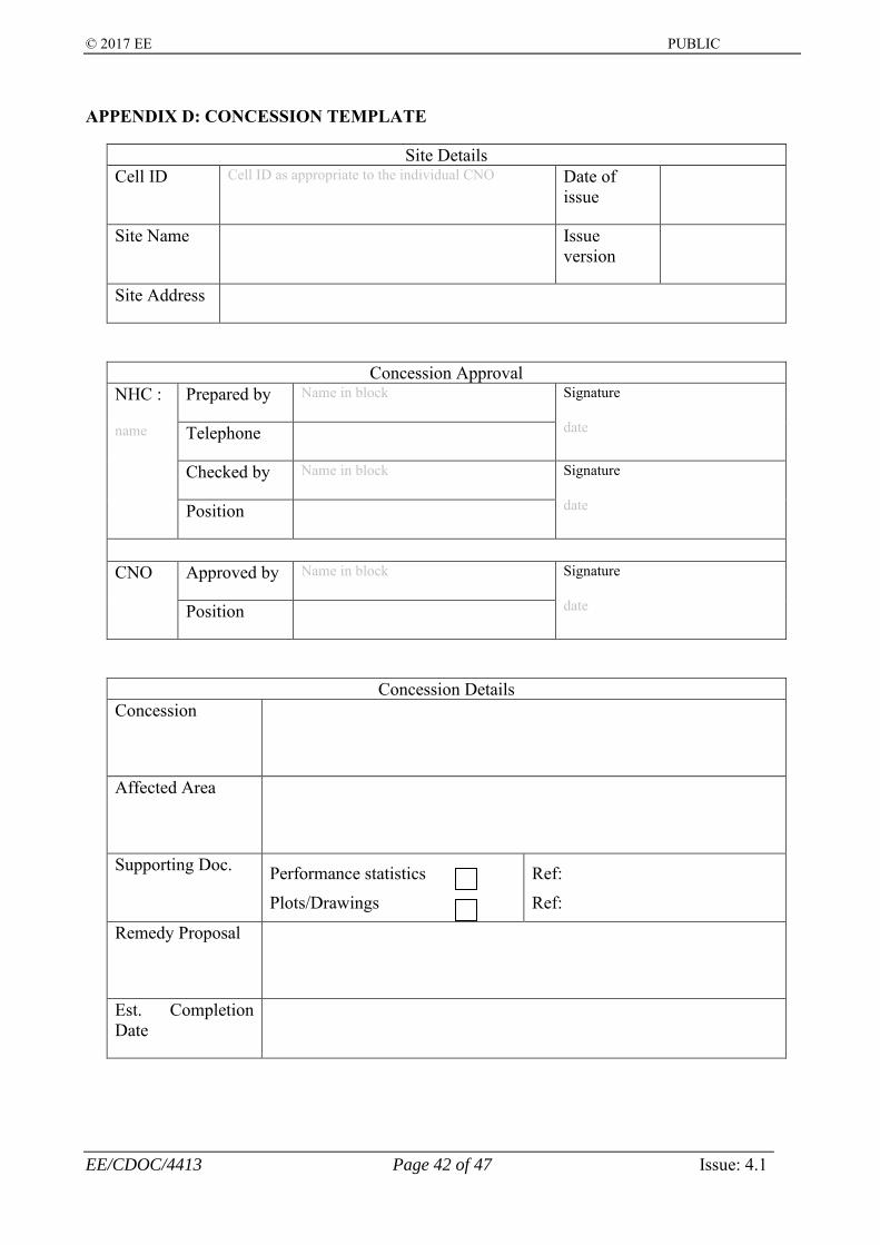
© 2017 EE PUBLIC
EE/CDOC/4413 Page 42 of 47 Issue: 4.1
APPENDIX D: CONCESSION TEMPLATE
Site Details Cell ID Cell ID as appropriate to the individual CNO Date of
issue
Site Name Issue version
Site Address
Concession Approval NHC :
name
Prepared by Name in block Signature
date Telephone
Checked by Name in block Signature
date Position
CNO Approved by Name in block Signature
date Position
Concession Details Concession
Affected Area
Supporting Doc. Performance statistics
Plots/Drawings
Ref:
Ref:
Remedy Proposal
Est. Completion Date

© 2017 EE PUBLIC
EE/CDOC/4413 Page 43 of 47 Issue: 4.1
APPENDIX E: SYSTEM LINK BUDGET SUMMARY TEMPLATE EXAMPLE
… etc. Where the radiating element is referred to the case of radiating cable instead of antenna, the radiating cable coupling loss of 95% should be defined and included under the column for the antenna gain. With reference to the template example above, as shown in figure E-1, SD,i is referred to the downlink system loss from the interface B to the remote active unit “i”, and SU,i is referred to the uplink sub-system loss from the remote active unit “i” to the interface B.
Figure E-1: Illustration of the link budget reference points.
Frequency band [MHz]: 800
active downlink gain [dB]
passive downlink loss [dB]
active uplink
gain [dB]
passive uplink
loss [dB]
couplers, splitters, filters etc
jumper-0.5m
jumper-1m
jumper-2m
jumper-3m
LDF2-50 (or
equivalent)
LDF4-50 (or
equivalent)
LDF5-50 (or
equivalent)1 A1-11 A1-21 A1-3...1 A1-m1 A1-n2 A2-12 A2-22 A2-3....2 A2-p
etc
antenna gain [dBi]
SD,i SU,iDAS zone
active DAS sub-system
antenna label
total RF component loss (end-to-end) [dB] total cable loss (end-to-end) [dB]
RBS
RBS
Interface B
Interfaces between RBS and Remote
Unit
Remote Unit
Remote Unit
M N
Antenna Note: N ≥ M
RI
SD,i
SU,i
Passive distribution & radiating
elements

© 2017 EE PUBLIC
EE/CDOC/4413 Page 44 of 47 Issue: 4.1
APPENDIX F: CONVERTING CW TEST RSSI RESULTS INTO GSM RXLEV, UMTS CPICH RSCP AND LTE RSRP
For the purpose of the downlink coverage tests as required and defined in section 5.2, if a narrow-band CW signal at an appropriate frequency is injected into the DAS at a power level different from the pilot power of the base station carrier, a normalisation factor has to be included for normalising the CW signal level into the equivalent top of rack carrier power (pilot) for each band and technology accordingly. The equivalent levels of GSM RxLev, UMTS CPICH RSCP and LTE RSRP should be presented accordingly. GSM, e.g.
• CW input to the POI “B” of DAS, Txlev_cw = 40dBm at the GSM band. • GSM BTS carrier power to the POI “B” of DAS, TxDLB = 43dBm. • Normalisation factor, X:
o X = Txlev_cw – TxDLB = 40 – 43 = -3dB, • To get the equivalent GSM RxLEV for a BCCH carrier from the measured narrow-
band CW RSSI, rxlev_cw, the normalisation factor have to be included • Equivalent BCCH RxLev = rxlev_cw – X , i.e. if rxlev_cw = -83dBm, the equivalent
BCCH RxLev will be -80dBm UMTS, e.g.
• CW input to the POI “B” of DAS, Txlev_cw = 40dBm at the UMTS band. • UMTS Node-B carrier power to the POI “B” of DAS = 43dBm • CPICH transmit power, TxDLB = 33dBm if 10% of 43dBm carrier is assigned to the
CPICH: 43dBm + 10 Log10 (10%) = 33dBm • Normalisation factor, X:
o X = Txlev_cw – TxDLB = 40 – 33 = +7dB • To get the equivalent CPICH RSCP from the measured narrow-band CW RSSI,
rxlev_cw, the normalisation factor have to be included • Equivalent CPCIH RSCP = rxlev_cw – X , i.e. if rxlev_cw = -83dBm, the equivalent
CPICH RSRP will be -90dBm LTE, e.g.
• Reference Symbol power of Reference Signal, TxDLB, is related to o the number of LTE OFDM sub-carriers within a given LTE channel bandwidth,
as noted in the table below, and LTE channel bandwidth, BWLTE [MHz] 1.4 3 5 10 15 20 number of sub-carriers 72 180 300 600 900 1200
a LTE sub-carrier power as a fraction of a full load carrier power 1/72 1/180 1/300 1/600 1/900 1/1200
a LTE sub-carrier power as a fraction of a full load carrier power, Fsub-carrier, [dB] -18.6 -22.6 -24.8 -27.8 -29.5 -30.8
o the power booster, PRS_booster, assigned to the Reference Signal (see section 2.2.) o TxDLB = PeNB + Fsub-carrier + PRS_booster , where PeNB is a carrier power of eNode-B
to the POI “B” of DAS o For the case of BWLTE = 20MHz leading to Fsub-carrier = -30.8dB, PRS_booster =3dB
and PeNB = 43dBm, TxDLB = 43dBm – 30.8dB + 3dB = 15.2dBm to the POI “B” of DAS

© 2017 EE PUBLIC
EE/CDOC/4413 Page 45 of 47 Issue: 4.1
• Thus, if a CW input to the POI “B” of DAS, Txlev_cw = 40dBm at the LTE band, the normalisation factor, X:
o X = Txlev_cw – TxDLB = 40 – 15.2 = +24.8dB • To get the equivalent LTE RSRP from the measured narrow-band CW RSSI, rxlev_cw,
the normalisation factor has to be included • Equivalent LTE RSRP = rxlev_cw - X , i.e.
o if rxlev_cw = -83dBm and Reference Symbol with 3dB power booster, the equivalent LTE RSRP will be -107.8dBm
As aforementioned, converting the measured narrow-band CW RSSI to the equivalent LTE RSRP is depended upon the LTE channel bandwidth, the full load carrier power and the Reference Symbol power booster regardless the received signal being referred to the SISO or MIMO transmission. The LTE RSRP is the linear average over the power contributions of the Resource Elements that carry cell-specific Reference Signals within the considered measurement frequency bandwidth. It can therefore only be referred to and measured in the OFDM symbols carrying reference symbols
It is also emphasised in here that all of the examples above are based upon the assumption of the CW coverage tests with a 0dBi antenna at the test receiver/scanner as a typical mobile handset receive antenna gain. If a higher gain antenna is used for the CW RSSI measurements, an appropriate offset should be included to establish the equivalent GSM BCCH RxLev, UMTS CPICH RSCP and LTE RSRP.
In terms of the presentation of the equivalent GSM BCCH RxLev, UMTS CPICH RSCP and LTE RSRP, the bin sizes as defined in section 5.2.2 and the corresponding legends as below should be followed. For a completeness, the bin sizes and legends for GSM RxQual, UMTS Ec/Io and LTE SNR are included.
legend GSM RxLev [dBm] UMTS CPICH RSCP [dBm] LTE RSRP [dBm] legend Uplink link loss [dB]≥-55 ≥-55 ≥-65 ≤60
(-55,-65] (-55,-65] (-65,-80] (60,80](-65,-75] (-65,-77] (-80,-95] (80,110](-75,-85] (-77,-87] (-95,-105] (110,120](-85,-95 ] (-87,-97 ] (-105,-110 ] (120,125](-95,-98] (-97,-100] (-110,-113] (125,130](-98,-101] (-100,-106] (-113,-116] (130,133](-101,-103] (-106,-109] (-116,-118] (133,136](-103, -106] (-109, -112] (-118, -121] >136
<-106 <-112 <-121
legend GSM RxQual (sub/full) UMTS Ec/Io [dB] LTE SNR [dB][1,3] >-4 >20
4 (-4,-8] (14,20]5 (-8,-10] (6,14]6 (-10,-13] (0,6]7 <-13 < 0
© 2017 EE PUBLIC
EE/CDOC/4413 Page 46 of 47 Issue: 4.1
JOINT OPERATOR APPROVAL
NAME: Adis Omeragic Head of Special Projects &
Events
NAME: Dave Sanderson Radio Design Manager
NAME: Julian Dorneanu In-Building & Special Projects Manager
NAME: Phil White Network Senior Manager

© 2017 EE PUBLIC
EE/CDOC/4413 Page 47 of 47 Issue: 4.1
DOCUMENT HISTORY
Issue Date Details 0.1 01/7/2005 Draft issued for comment. 0.2 12/10/2005 Updated draft issued for comment 0.3 02/11/2005 Updated draft issued for comment 0.4 20/04/2006 Updated draft issued for comment 0.5 02/05/2006 Updated draft issued for final comment 0.6 22/05/2006 Updated draft issued for final comment 1.0 18/07/2006 Final issue (Spec for GSM & UMTS) 2.0 09/04/2008 Update of Issue 1 with the main changes of section 5 (formal issue, Spec for GSM
& UMTS) 2.1 24/04/2009 Update for comment with reduction of the system tests (not formal issue) 2.2 28/07/2011 Update with the LTE draft 2.3 24/10/2011 Update with the LTE draft 2.4 22/05/2012 Update with LTE draft & the requirements for tunnel 2.5 15/01/2013 Update with the LTE draft for final comment 3.0 15/02/2013 Formal issue (Spec GSM, UMTS & LTE) 3.1 05/04/2013 Correction of Appendix-A Licensed Spectrum (reverse DL & UL) 3.2 03/02/2014 Document classification changed from “Internal” to “Public” 3.3 06/04/2017 CNO internal Review ONLY 4.0 12/06/2017 Formal issue 4.1 13/07/2017 Further minor update after the Joint-Operators and Indoor Cellular System
Suppliers/Neutral Hosts meeting dated 23rd June 2017.
TITLE - JOINT OPERATORS TECHNICAL SPECIFICATION OF GSM, UMTS & LTE INDOOR CELLULAR SYSTEM DOCUMENT APPROVAL OWNER/AUTHOR (SIGNED) NAME (BLOCK CAPITALS): KIN WAN
OWNERSHIP & CONFIDENTIALITY Everything Everywhere is the trading name of Everything Everywhere Limited. No part of this document may be disclosed orally
or in writing, including by reproduction, to any third party without the prior written consent of Everything Everywhere Limited .This document, its associated appendices and any attachments remain the property of Everything Everywhere Limited and
shall be returned upon request.