
Joint design of communication and sensing for Beyond 5G ...
26
Joint design of communication and sensing for Beyond 5G and 6G systems White paper The 6G vision of creating authentic digital twin representations of the physical world calls for new sensing solutions to compose multi-layered maps of our environments. Radio sensing using the mobile communication network as a sensor has the potential to become an essential component of the solution. With the evolution of cellular systems to mmWave bands in 5G and potentially sub-THz bands in 6G, small cell deployments will begin to dominate. Large bandwidth systems deployed in small cell configurations provide an unprecedented opportunity to employ the mobile network for sensing. In this paper, we focus on the major design aspects of such a cellular joint communication and sensing (JCAS) system. We present an analysis of the choice of the waveform that points towards choosing the one that is best suited for communication also for radar sensing. We discuss several techniques for efficiently integrating the sensing capability into the JCAS system, some of which are applicable with NR air-interface for evolved 5G systems. Specifically, methods for reducing sensing overhead by appropriate sensing signal design or by configuring separate numerologies for communications and sensing are presented. Sophisticated use of the sensing signals is shown to reduce the signaling overhead by a factor of 2.67 for an exemplary road traffic monitoring use case. We then present a vision for future advanced JCAS systems building upon distributed massive MIMO and discuss various other research challenges for JCAS that need to be addressed in order to pave the way towards natively integrated JCAS in 6G.
Transcript of Joint design of communication and sensing for Beyond 5G ...

Joint design of communication and sensing for Beyond 5G and 6G systems White paper
The 6G vision of creating authentic digital twin representations of the physical world calls for new sensing solutions to compose multi-layered maps of our environments. Radio sensing using the mobile communication network as a sensor has the potential to become an essential component of the solution. With the evolution of cellular systems to mmWave bands in 5G and potentially sub-THz bands in 6G, small cell deployments will begin to dominate. Large bandwidth systems deployed in small cell configurations provide an unprecedented opportunity to employ the mobile network for sensing. In this paper, we focus on the major design aspects of such a cellular joint communication and sensing (JCAS) system. We present an analysis of the choice of the waveform that points towards choosing the one that is best suited for communication also for radar sensing. We discuss several techniques for efficiently integrating the sensing capability into the JCAS system, some of which are applicable with NR air-interface for evolved 5G systems. Specifically, methods for reducing sensing overhead by appropriate sensing signal design or by configuring separate numerologies for communications and sensing are presented. Sophisticated use of the sensing signals is shown to reduce the signaling overhead by a factor of 2.67 for an exemplary road traffic monitoring use case. We then present a vision for future advanced JCAS systems building upon distributed massive MIMO and discuss various other research challenges for JCAS that need to be addressed in order to pave the way towards natively integrated JCAS in 6G.
2 White paperJoint design of communication and sensing for Beyond 5G and 6G systems
Contents
Introduction 3
Key drivers and use cases 5
Drivers for integration of sensing and communication in future mobile cellular systems 5
Sensing applications and their requirements 7
System design and technology 8
System resources and signal parameters 8
Waveforms and processing 9
Integration of radar in cellular mobile communication system 13
Need for advanced signal processing concepts enhanced by AI/ML 18
Further visions for advanced JCAS design 19
New research directions 20
Discussion and outlook 21
Abbreviations 22
Acknowledgments 23
References 23

3 White paperJoint design of communication and sensing for Beyond 5G and 6G systems
IntroductionFive generations of wireless communication systems are deployed and offer, with 5G New Radio (NR) [1], high data rates and ultra-reliable, low-latency services. Industrial automation systems start to integrate 5G in their design [2], e.g. for equipping factories of the future in Industry 4.0. At this juncture, academic and industry research is shifting focus towards 6G. Numerous papers outlining the vision and technologies for 6G have been published [3]-[12]. A common theme in many of these works is that the 6G network will be designed for simultaneous communication and sensing, turning the network into a sensor to create a digital sixth sense augmenting human intelligence. Sensing solutions are also essential for an authentic digital representation of the physical world enabling new human experiences through immersive mixed reality digital worlds.
Network sensing refers to the detection of the presence of objects, their shape, location and speed of movement using radio signals transmitted and received by network elements. Sensor fusion, which combines network sensing data with that of other sensors such as location tags, or sensors ubiquitously employed in devices such as accelerometers, gyroscopes and cameras, will be used to provide the complete sensing solution needs of the 6G era.
Beyond pure communication services, LTE and 5G already offer possibilities for active positioning with standardized protocols to connect network elements and devices to a central localization management function by means of the LTE Positioning Protocol (LPP) and the NR Positioning Protocol A (NRPPa), respectively. Localization of a user carrying a 5G device can be achieved with the NR air interface via various methods using either uplink or downlink signals with time difference of arrival or angle of arrival estimates [13]. This provides benefits especially for indoor scenarios where global navigation satellite system (GNSS) reception is too weak for accurate localization. One limitation of 5G localization is that objects or users that need to be localized must carry an active 5G device. Similarly, active sensors that communicate their measured data through the 4G/5G network can be employed to gather information other than location through the network.
Figure 1. Basic scenario illustration for JCAS in cellular systems with beamforming antennas, user equipment (UE) for data transmission and sensing objects/persons.
Cell k
Cell k
UE #1
JCAS BS
UE #2
Arrayantenna
Beam 2Beam 2
Beam 1
Beam 3
Sensingobject/person
4 White paperJoint design of communication and sensing for Beyond 5G and 6G systems
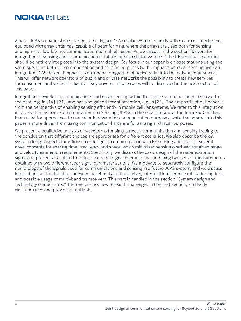
A basic JCAS scenario sketch is depicted in Figure 1: A cellular system typically with multi-cell interference, equipped with array antennas, capable of beamforming, where the arrays are used both for sensing and high-rate low-latency communication to multiple users. As we discuss in the section “Drivers for integration of sensing and communication in future mobile cellular systems,” the RF sensing capabilities should be natively integrated into the system design. Key focus in our paper is on base stations using the same spectrum both for communication and sensing purposes (with emphasis on radar sensing) with an integrated JCAS design. Emphasis is on inband integration of active radar into the network equipment. This will offer network operators of public and private networks the possibility to create new services for consumers and vertical industries. Key drivers and use cases will be discussed in the next section of this paper.
Integration of wireless communications and radar sensing within the same system has been discussed in the past, e.g. in [14]-[21], and has also gained recent attention, e.g. in [22]. The emphasis of our paper is from the perspective of enabling sensing efficiently in mobile cellular systems. We refer to this integration in one system as Joint Communication and Sensing (JCAS). In the radar literature, the term RadCom has been used for approaches to use radar hardware for communication purposes, while the approach in this paper is more driven from using communication hardware for sensing and radar purposes.
We present a qualitative analysis of waveforms for simultaneous communication and sensing leading to the conclusion that different choices are appropriate for different scenarios. We also describe the key system design aspects for efficient co-design of communication with RF sensing and present several novel concepts for sharing time, frequency and space, which minimizes sensing overhead for given range and velocity estimation requirements. Specifically, we discuss the basic design of the radar excitation signal and present a solution to reduce the radar signal overhead by combining two sets of measurements obtained with two different radar signal parameterizations. We motivate to separately configure the numerology of the signals used for communications and sensing in a future JCAS system, and we discuss implications on the interface between baseband and transceiver, inter-cell interference mitigation options and possible usage of multi-band transceivers. This part is handled in the section “System design and technology components.” Then we discuss new research challenges in the next section, and lastly we summarize and provide an outlook.

5 White paperJoint design of communication and sensing for Beyond 5G and 6G systems
Key drivers and use casesDrivers for integration of sensing and communication in future mobile cellular systemsRadar systems have been extensively deployed in numerous applications for the military, and for aircraft and vehicles, etc. Similarly, active sensors for motion, temperature, humidity, air quality, waste management, and accelerometers, gyroscopes and cameras are widely used in commercial applications and rely on the mobile cellular network for communication. However, mobile systems have not commercially been applied towards sensing of the environment using radar techniques. A research implementation example for LTE and NR is discussed in [23]. Cellular systems prior to 5G have limited signal bandwidths, and base stations have been typically deployed in macro-cell configuration, which limits the achievable sensing accuracy. On the other hand, the introduction of wider bandwidth systems in 5G combined with dense small cell deployments makes it greatly promising to use these systems for sensing. The lean, forward-compatible 5G air interface design, as discussed in the section entitled “Integration of radar in cellular mobile communication system,” enables introduction of sensing features in future releases, beyond active positioning. While active positioning and active sensors can meet the sensing requirements, not every person, good, or object carries a device or tag at all times, so additional techniques beyond active sensors are needed. It will be appealing for communication systems of the future (including also evolutions of NR) to systemically integrate RF sensing capabilities, which can be made available over large areas because of contiguous area coverage of cellular systems and the large amount and density of base station (BS) sites, even if the sensing range of an individual BS is limited (e.g. for one BS this would be considered a short-range radar).
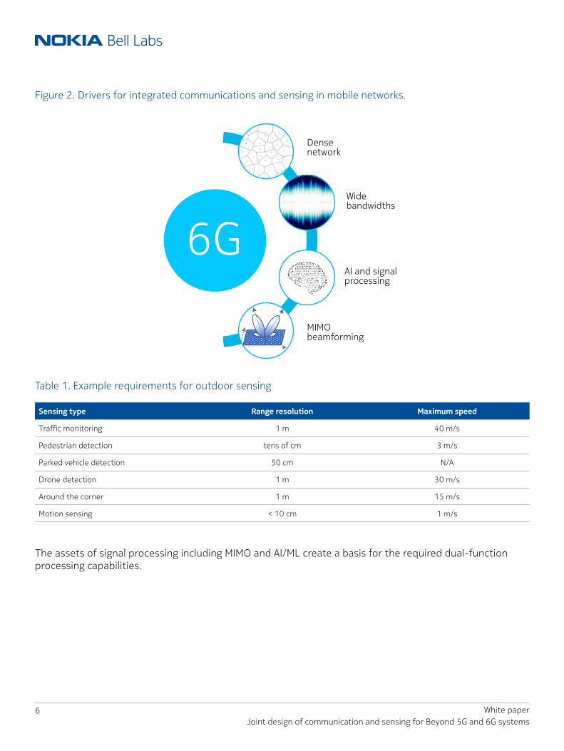
In 6G, we expect native JCAS support, where the key drivers for designing sensing capabilities into mobile networks, illustrated in Figure 2, are as follows:
• Spectrum is a scarce resource, and using it for both sensing and communication simultaneously is more efficient than dedicated spectrum usage.
• Cellular systems are becoming ubiquitous with increasing density, and are also moving inside vertical industries, e.g. factories. This deployment density provides the opportunity to enable RF sensing over a wide area with common infrastructure and spectrum reuse.
• RF sensing can benefit from economies of scale in the wireless communications industry. One single combined installed system eases deployment and maintenance.
• Signal bandwidths are increasing over the generations with 20 MHz carriers in LTE, 100 MHz in sub-6 GHz 5G NR and 400 MHz for mmWave NR. New bands for 5G evolution and 6G are expected to have higher bandwidths on the order of 1 GHz or more, which will provide high-resolution sensing possibilities.
• RF signals intrude less on privacy than cameras, which are not allowed to be installed everywhere. RF signals also propagate well under conditions that are difficult for cameras and other sensors in real-world environments with dust, bad weather, or poor lighting especially during the night, etc.
• Massive MIMO [24] deployment and spatial processing techniques are already key components in 5G, which also substantially enhance radio sensing performance.
The recent advances in artificial intelligence (AI) and machine learning (ML) for communication systems [25] pave the way for AI/ML to become an integral part of the design of beyond 5G (B5G) and 6G systems (e.g. [3],[5]).
6 White paperJoint design of communication and sensing for Beyond 5G and 6G systems
Figure 2. Drivers for integrated communications and sensing in mobile networks.
6G
Densenetwork
Widebandwidths
AI and signalprocessing
MIMObeamforming
Table 1. Example requirements for outdoor sensing
Sensing type Range resolution Maximum speed
Traffic monitoring 1 m 40 m/s
Pedestrian detection tens of cm 3 m/s
Parked vehicle detection 50 cm N/A
Drone detection 1 m 30 m/s
Around the corner 1 m 15 m/s
Motion sensing < 10 cm 1 m/s
The assets of signal processing including MIMO and AI/ML create a basis for the required dual-function processing capabilities.

7 White paperJoint design of communication and sensing for Beyond 5G and 6G systems
Sensing applications and their requirementsSensing indoors using Wi-Fi signals has been extensively studied and covers a large number of use cases; see for example [26] and the extensive list of references therein. The use of radio sensing outdoors and in industrial environments such as factory floors seem less studied. Some examples of outdoor use cases with sensing requirements that are potentially achievable with cellular systems are as follows. The requirements are captured in Table 1.
• Traffic monitoring involving the estimation of the number of cars and their speeds in a given section of the road during a given time period. The range resolution should be smaller than the typical vehicle size and the maximum velocity estimation targeted should exceed highway speeds.
• A classic example of outdoor sensing is identification of parking spots in busy city streets. The range resolution should be smaller than the typical vehicle dimensions. Additionally, some reference localization will be needed to provide accurate information.
• Around the corner vehicle detection is a use case in which an access point located on one street is able to detect vehicles approaching an intersection from a cross street. This is a challenging use case since it involves non-line-of-sight propagation. For the detection of vehicular traffic, the range resolution should again be smaller than expected vehicle dimensions.
• Detecting pedestrians crossing streets is a use case that can improve road safety by sending that information as a warning to drivers [13]. Accuracy on the direction of movement is critical to discern whether the user is moving along the street or across the street. Range resolution should be comparable to human body dimensions. Higher carrier frequencies are better suited due to fewer diffraction effects.
• Counting the number of people within a local area such as a public square requires range resolution less than a fraction of a meter to differentiate between individuals.
• Detection of unidentified drones or other flying objects can be performed with cellular systems, for example, if designed to cover the lower airspace. Range resolution of a fraction of a meter will be required.
• In rural environments, radio sensing can be used to detect humidity levels for agricultural applications.
5G has been designed to meet ultra-reliable low-latency communication (URLLC) requirements and is thus expected to be widely deployed for industrial automation in many vertical industries. Furthermore, 5G includes features to enable precision localization of 5G devices, enabling factories and other verticals to deploy a single system to satisfy both communication and localization needs. Radio sensing capability will further increase the utility of cellular systems in factory automation by supporting several use cases. Some examples include:
• Detecting the presence of people within geo-fenced areas of the factory;
• Accurate localization and tracking of large passive objects. Passive means that active radio transmitters, e.g. for active uplink localization, are not present in those objects. Centimetre level accuracy may be needed.
• Collision avoidance between autonomous guided vehicles or other mobile robots and people to ensure better safety;
• Estimating the height of stacked pallets or containers in the warehouse.
As discussed in [3][5], it is expected that B5G/6G communication systems target to further expand air interface capabilities towards supporting extreme URLLC services, so future cellular generations beyond 5G are expected to play an even stronger role in industrial environments, including sensing capabilities for factories.

8 White paperJoint design of communication and sensing for Beyond 5G and 6G systems
System design and technologySystem resources and signal parametersJoint design of communication and sensing requires careful optimization of the available system resources between the two functions to meet their respective target requirements. Table 2 shows the available system resources in space, time, frequency as an extended version of what is in [20], and their resulting impact on both the radar and communications service.
Low-latency support is a key capability of 5G and beyond communication systems and thus the time domain allocation of resources for the radar signal transmission needs particular attention. The time intervals between the different periodic sensing beam allocations determine the burst frequency (or beam revisit rate). The total time-limited contiguous length of the sensing allocation is denoted as burst duration (or beam dwell). For communication purposes, how soon transmit opportunities are available immediately upon packet arrival at the BS or user equipment (UE) in a certain beam direction determines the achievable communication latency. For a JCAS system, this motivates a time domain comb design in combination with beam sweeping with the least possible interruption to data transmission opportunities. The details of the multiple access and resource allocation design are discussed in the section entitled “Integration of radar in cellular mobile communication system.”
Table 2. Key system resources and resulting service impact
System resourceSystem service
Radar Communications
Space Beam directions and shape Volume coverage Throughput and coverage
Time
Burst frequency/beam revisit rate
Coverage rate and max. velocity Latency
Burst duration/beam dwell/integration time
Detection range and velocity resolution
Throughput
Frequency Signal bandwidth Range resolution Throughput and reliability
Power/EIRPPA/linearization, power consumption
Volume coverage Throughput and coverage
The usage of beamforming and MIMO is already an essential part of 5G, improving spectral efficiency of the communication system. Exploiting directivity from beamforming is imperative especially for higher carrier frequencies in order to achieve sufficient coverage and cell range. Similarly, beamforming will also improve sensing range and coverage. Antenna arrays that form the beams can also be treated as a hardware resource that can be devoted to communication or sensing when multiple antenna panels are part of the antenna system. Larger antenna apertures lead to more narrow beams; beams are spatial radio resources.
Power is a key system resource for both communication as well as sensing. With increasing carrier frequencies, the power efficiency decreases and thus the choice of the waveform becomes more important as it determines required power amplifier (PA) back-offs. This is discussed in the following section, “Waveforms and processing.” That section also discusses the issue of full duplex transceivers and alternatives to partially avoid the need for full duplex. One approach is to distribute antenna systems for JCAS, which is addressed in the section entitled “Further visions for advanced JCAS design.”

9 White paperJoint design of communication and sensing for Beyond 5G and 6G systems
Table 2 does not explicitly list hardware processing resources, but it should be mentioned that native AI design for 6G communication systems will provide the necessary AI/ML processing components, e.g. using tensor processing units (TPUs) for massive parallelization of neural network related processing. This is an excellent basis for shared processing resources when it comes to AI/ML algorithms for sensing, which we address in the section entitled “Need for advanced signal processing concepts enhanced by AI/ML.”
Waveforms and processingIn this section we discuss candidate waveforms for radar and communication in conjunction with the RF processing chain. To evaluate the suitability of different waveforms, the three primary aspects of peak-to-average power ratio (PAPR), signal processing complexity, and full duplex implementation are discussed first, and other aspects are summarized subsequently.
PAPR and RF impactThe dominating communication waveform of current 4G and 5G systems is orthogonal frequency division multiplexing (OFDM) (in combination with vendor-specific filtering and/or windowing). With the design of orthogonal subcarriers, OFDM provides excellent multiplexing capabilities in time and frequency via OFDM resource elements. Because of the cyclic prefix, the linear convolution of the transmit signal with the propagation channel impulse response is turned into a circular convolution, allowing for simple frequency domain equalization at the receiver. The only drawback of OFDM is its high PAPR, which necessitates a power back-off for the PA and reduces the energy efficiency of the transmitter. The PAPR of OFDM can be somewhat reduced by signal conditioning [27]. In cases where energy efficiency becomes more important, there is the possibility to apply DFT-spreading on top of OFDM, also known as single-carrier frequency division multiple access (SC-FDMA). SC-FDMA is applied in LTE uplink and optionally in NR uplink. SC-FDMA is particularly useful in the higher carrier frequency bands, a.k.a. frequency range 2 (FR2), which is supported in NR Rel-16 up to 52.6 GHz carrier frequency.
6G is expected to include even higher carrier frequency bands beyond 100 GHz, a.k.a. the sub-THz frequency range. PA technology in such bands has a low power efficiency, output power is limited and therefore PAPR is even more of an issue [28]. The PAPR of the selected waveform(s) will impact the supported range both for communication and sensing, which thus matters especially for carrier frequencies in the mmW range and above.
Besides SC-FDMA, another low-PAPR waveform candidate for 6G in these high-frequency bands is single carrier frequency domain equalization (SC-FDE) [29] where a cyclic prefix is added to allow for frequency domain equalization. In a further alternative variant for sub-THz communications, the single carrier waveform concept is matched to a low-resolution analog-to-digital conversion (ADC) receiver for enhanced energy efficiency at the receive side [30]. The information content is transported in zero-crossings using faster-than-Nyquist signaling, run-length limited sequences and oversampling at the receiver side.
For stand-alone short-range radar processing, the typical waveform and RF are based on frequency-modulated continuous wave (FMCW) transmission of chirp signals [31], where within one chirp interval a signal with, for example, a linear increase in transmit frequency is transmitted. The reflected received signal is shifted by the so-called beat frequency, which is a function of range and Doppler. The PAPR of a chirp signal is inherently low, which is a clear benefit.
Communication capabilities of FMCW are discussed in [44] and [45]. However, the key drawback of FMCW is the limited capability to carry data and so FMCW alone is not a good basis for the challenging communication data rate needs of 6G systems. However, FMCW signals can in principle be time multiplexed into the air interface of a JCAS system, as discussed in [26].
10 White paperJoint design of communication and sensing for Beyond 5G and 6G systems
Signal processing complexityThe processing of the received radar signal typically consists of 2D-FFT for extracting echo delay (range) and Doppler (velocity). In the case of conventional FMCW short-range radar, range and Doppler are not orthogonally decoupled after 2D-FFT, as the beat frequency is a function of range and Doppler [31].
OFDM radar [14]-[17] is a more recent alternative for short-range radar. Arbitrary information-bearing or pilot-bearing modulation symbols mapped to the OFDM resource elements can be used at the transmitter side. In typical processing, the OFDM radar receiver divides the received modulation symbols by the known transmit modulation symbols, so that a (noisy) channel frequency response is obtained. An FFT along the subcarrier dimension provides the range, while an IFFT in time direction across multiple OFDM symbols provides the Doppler. Thus, processing in range and Doppler become orthogonal, which has the benefit that range accuracy is not negatively impacted by limited Doppler measurement accuracy. This explicit channel knowledge is very beneficial for advanced signal processing purposes, e.g. for training AI/ML systems on detection of presence and shape of objects as discussed in the section entitled “Need for advanced signal processing concepts enhanced by AI/ML.”
Instead of FMCW or OFDM signals, in principle any waveform can be used for short-range radar excitation, where, for example, single carrier modulation provides the above mentioned PAPR benefits. Single carrier signals with cyclic prefix (SC-FDMA, SC-FDE) preserve the cyclic convolution property in a multi-path channel and allow for symbol-based frequency domain processing in a very similar way as with OFDM, i.e., the frequency domain receive symbols (similar to received OFDM modulation symbols) can be divided by the respective frequency domain transmit symbols prior to the 2D-FFT radar processing. Note that in the frequency domain, some single carrier signal components of the transmit signal may be zero or near zero, which may cause a noise enhancement after the division. Compared to OFDM, this will create an accuracy loss.
In the absence of a cyclic prefix (e.g. in case of spread spectrum single carrier), single carrier radar typically uses a correlation-based receive processing [15], which is simple to implement if, for example, only the range is of interest. As range and Doppler are not decoupled with correlation-based processing, this increases the processing effort for mobile objects compared to 2D-FFT processing with cyclic prefix-based waveforms.

11 White paperJoint design of communication and sensing for Beyond 5G and 6G systems
Full duplex
Figure 3. Antenna constellation with a) full array gain for communications and b) array partitioning for radar.
b) Partitioned array
Simultaneous Txand Rx for radar
Tx data
Rx data
Sub-array1
Sub-array2
Sub-array1
Sub-array2
Sub-array1
Sub-array2
a) Full array
Short-range radar requires simultaneous transmission and reception on the same frequency. Applying OFDM or single-carrier waveforms in cellular communication systems for short-range radar therefore results in a full duplex challenge. Current communication systems including 5G are based on either time division duplexing (TDD) or frequency division duplexing (FDD) and thus are not simultaneously transmitting and receiving at the same frequency as this would create large self-interference to be handled. This self-interference would need to be mitigated [23] by a combination of antenna separation, as well as analog and digital interference cancellation. Antenna separation and analog interference cancellation ensure that the possible dynamic range of the quantized ADC output is not violated, and the digital processing removes the residual self-interference parts. Both analog and digital cancellation are corrupted with imperfections and thus the system will support only a limited propagation range. For 6G, an alternative JCAS design could be to rely as far as possible on (passive) antenna separation and make use of cooperative processing, as discussed in the section “Further visions for advanced JCAS design.”

12 White paperJoint design of communication and sensing for Beyond 5G and 6G systems
Table 3. JCAS waveform candidates
KPI FMCW OFDM Single carrier FMCW + OFDM FMCW + SC
PAPR ++ -- + ++/-- ++/+Cost RF + - - -- --Full duplex effort + - - + +Cost BB + - - - -Carry data -- ++ ++ + +Commun. proc. flexibility -- ++ + + +User MUX - ++ + ++ +Radar proc. accuracy + + - + +Full CSI available for sensing - ++ + - -
Antenna separation in a JCAS system, which may be needed for short-range radar capability, can be implemented by partitioning the antenna array used for communications along the horizontal, vertical or polarization domain, as depicted in Figure 3. Partitioning the array into two equal-sized subarrays is a reasonable approach to achieve similar beam widths between radar transmission and reception. While the full array gain is then available for data transmission and reception, the reduced antenna gain for radar will cause a 6dB penalty in receive signal-to-noise ratio (SNR), and possibly some additional loss in diversity. (Processing gain, as discussed in the section “Integration of radar in cellular mobile communication system” below, can compensate for it). Implications on system design are that the interface between baseband and RF processing may need to signal the array partitioning in real time. An alternative to array partitioning is to deploy a separate antenna array for the radar receiver. In this case this extra array may also be used for enhancing the performance of active localization and/or uplink data reception.
Discussion of waveform candidatesA qualitative comparison of different waveform candidates is provided in Table 3. The second (FMCW), third (OFDM) and fourth (SC) columns of Table 3 assume that a single waveform is used for the JCAS system, while the latter two columns assume time division multiplexing of separate waveforms for sensing (FMCW) and communications (OFDM or SC). The split PAPR entry for the two right columns refers to the time multiplexing, first value for FMCW, second value for the other waveform. The respective waveforms are indicated in the column headers. Frequency multiplex of separate waveforms on the same carrier is not suggested for the JCAS system due to the need for guard bands and loss of range resolution for sensing.
Communication processing flexibility refers to the possibility to embed pilot and control information and ease of use of MIMO algorithms. Time-multiplexing of FMCW and other waveforms may require duplication of certain RF hardware components but could help to ease the full duplex challenge. Further research is needed to determine whether such hybrid dual waveform systems are beneficial despite this extra hardware complexity.
For drawing conclusions on the waveform choice, the different factors considered in the qualitative comparison should be weighted differently depending on the operating carrier frequency. OFDM shines as it is both excellent to carry data and extract sensing information. The OFDM received resource elements after division by transmitted modulation symbols naturally contain the time-variant frequency-selective
13 White paperJoint design of communication and sensing for Beyond 5G and 6G systems
channel frequency response. Communication systems are already operating with OFDM and its only considerable downside is the poor PAPR. The prerequisite is that the full duplex self-interference problem is handled as discussed above and in the section entitled “Further visions for advanced JCAS design.”
5G evolution or 6G systems operating in lower carrier frequency ranges (FR1, up to 6 GHz and potentially parts of FR2 with some tens of GHz) do not have an extremely stringent PAPR requirement. Those systems should use OFDM for JCAS. In the higher carrier frequencies, e.g. sub-THz, systems for JCAS should preferably use single carrier modulation. Hence, our qualitative comparison in Table 3 points to choosing the waveform that is best suited for communication also for radar sensing.
Integration of radar in cellular mobile communication system
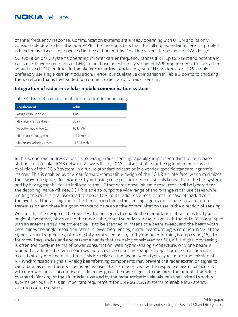
Table 4. Example requirements for road traffic monitoring
Requirement Value
Range resolution Δd 1 m
Maximum range dmax 80 m
Velocity resolution Δv 10 km/h
Minimum velocity vmin -150 km/h
Maximum velocity vmax +150 km/h
In this section we address a basic short-range radar sensing capability implemented in the radio base stations of a cellular JCAS network. As we will see, JCAS is also suitable for being implemented as an evolution of the 5G NR system, in a future standard release or in a vendor-specific standard-agnostic manner. This is enabled by the lean forward-compatible design of the 5G NR air interface, which minimizes the always-on signals, for example, by not using cell-specific reference signals known from the LTE system, and by having capabilities to indicate to the UE that some downlink radio resources shall be ignored for the decoding. As we will see, 5G NR is able to support a wide range of short-range radar use cases while limiting the radar signal overhead to about 10% of its radio resources, or less. In case of loaded cells, the overhead for sensing can be further reduced since the sensing signals can be used also for data transmission and there is a good chance to have an active communication user in the direction of sensing.
We consider the design of the radar excitation signals to enable the computation of range, velocity and angle of the target, often called the radar cube, from the reflected radar signals. If the radio BS is equipped with an antenna array, the covered cell is to be scanned by means of a beam sweep, and the beam width determines the angle resolution. While in lower frequencies, digital beamforming is common in 5G, at the higher carrier frequencies, often digitally-controlled analog or hybrid beamforming is employed [46]. Thus, for mmW frequencies and above (some bands that are being considered for 6G), a full digital processing is often too costly in terms of power consumption. With hybrid/analog architecture, only one beam is scanned at a time. The term beam sweep refers to computing a range-Doppler profile on all beams in a cell, typically one beam at a time. This is similar as the beam sweep typically used for transmission of NR synchronization signals. Analog beamforming components may prevent the radar excitation signal to carry data, as often there will be no active user that can be served by the respective beam, particularly with narrow beams. This motivates a lean design of the radar signals to minimize the potential signaling overhead. Blocking of the air interface caused by the radar excitation signals must be limited to within sub-ms periods. This is an important requirement for B5G/6G JCAS systems to enable low-latency communication services.

14 White paperJoint design of communication and sensing for Beyond 5G and 6G systems
Given these system constraints, the dimensioning of numerology and time-frequency allocation of the radar excitation signal is primarily driven by the requirements concerning range and velocity resolution and their respective non-ambiguous maximum values. This basic dimensioning applies similarly for different waveforms or whether the excitation signals carry data or not. A set of possible requirements is exemplified in Table 4 for a road traffic monitoring use case. To enable a flexible deployment of the radar we will dimension for an effective velocity range of [-vmax … +vmax]. In this case the radar processing will provide the motion direction and relative velocity. In scenarios where the motion direction is known, the effective velocity range can be limited to [0 … vmax] to reduce signaling overhead.
Table 5 summarizes the basic dimensioning parameters of the radar excitation signal for the requirements of Table 4, where c denotes the velocity of light, d and v denote the target range and velocity, respectively, fc denotes the carrier frequency, and veff = vmax - vmin denotes the effective velocity range. Derivations of the underlying dependencies can be found in, for example, [14-17].
Table 5. Basic dimensioning of radar excitation signal
Radar signal parameter Dependency NR at 28 GHz
Minimum subcarrier spacing ~20vmaxfc/c 120 kHz
Minimum guard interval 2dmax/c Normal CP
Minimum bandwidth c/2/Δd 150 MHz
Minimum burst duration c/2/Δv/fc 2 ms
Maximum time domain spacing c/2/fc/veff 7 symbols
Maximum frequency domain spacing c/2/dmax 15 subcarriers
The basic signal design is motivated as follows:
• The minimum subcarrier spacing (SCS) in OFDM case shall be about 10x the maximum Doppler frequency. Hence 120 kHz SCS would be suitable to support target velocities up to ≈230 km/h. For road traffic monitoring, often 60 kHz SCS may be sufficient, however, compared to 120 kHz SCS the symbol duration is doubled, which, as we will see, will double the signaling overhead for radar excitation for a given effective velocity range.
• The minimum guard interval is the time interval until the latest radar echo signal is received, thus it is proportional to the maximum target distance. It is typically ignored by the short-range radar signal processing, similar to the cyclic prefix (CP) with NR system. Normal CP of NR supports a range of up to about 88 m with 120 kHz SCS.
• The minimum required bandwidth is inversely proportional to the range resolution. Sub-meter range resolution is obtained with a bandwidth >150 MHz, well below the 400 MHz per carrier supported by NR in FR2.
• The minimum burst duration is the time span over which the radar excitation signal shall extend when computing the Doppler profile. It is inversely proportional to velocity resolution and carrier frequency. The burst duration may span over several NR slots, for example, over 16 slots to achieve <10 km/h velocity resolution with 120 kHz SCS (0.125 ms NR slot duration).

15 White paperJoint design of communication and sensing for Beyond 5G and 6G systems
• The processing gain (PG) is given as the number of symbols times the number of subcarriers [14]. With 32 symbols distributed over 2 ms and ~1250 subcarriers in 150 MHz, it would amount to about 46 dB, which is strong and could compensate for power losses from array splits as mentioned above in the section on “Full duplex”.
Figure 4a. Time interleaved signal allocation for a particular beam. Black: Sensing, White: Communication data.
…
→
→
…
…
→
→
beam p
beam p+1
Symbols
NR slots
Symbols
NR slotsSlot Slot
Slot Slot
Figure 4b. Time interleaved signal allocation for two beams.
…
→
→
…
…
→
→
beam p
beam p+1
Symbols
NR slots
Symbols
NR slotsSlot Slot
Slot Slot
Figure 5. Exemplary time-frequency grid structure of radar excitation signal within a NR physical resource block
↑
↑ Subcarriers→ Symbols
Cell ID mod 3
Cell 2Cell 1Cell 0
0
012012
012012
67891011
012345
1 3 3 4 5 6 7 8 9 10 11 12 13
16 White paperJoint design of communication and sensing for Beyond 5G and 6G systems
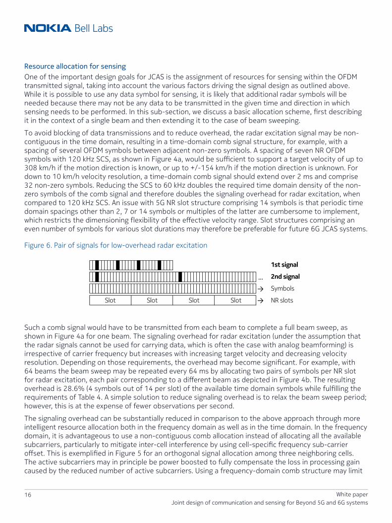
Resource allocation for sensing One of the important design goals for JCAS is the assignment of resources for sensing within the OFDM transmitted signal, taking into account the various factors driving the signal design as outlined above. While it is possible to use any data symbol for sensing, it is likely that additional radar symbols will be needed because there may not be any data to be transmitted in the given time and direction in which sensing needs to be performed. In this sub-section, we discuss a basic allocation scheme, first describing it in the context of a single beam and then extending it to the case of beam sweeping.
To avoid blocking of data transmissions and to reduce overhead, the radar excitation signal may be non-contiguous in the time domain, resulting in a time-domain comb signal structure, for example, with a spacing of several OFDM symbols between adjacent non-zero symbols. A spacing of seven NR OFDM symbols with 120 kHz SCS, as shown in Figure 4a, would be sufficient to support a target velocity of up to 308 km/h if the motion direction is known, or up to +/-154 km/h if the motion direction is unknown. For down to 10 km/h velocity resolution, a time-domain comb signal should extend over 2 ms and comprise 32 non-zero symbols. Reducing the SCS to 60 kHz doubles the required time domain density of the non-zero symbols of the comb signal and therefore doubles the signaling overhead for radar excitation, when compared to 120 kHz SCS. An issue with 5G NR slot structure comprising 14 symbols is that periodic time domain spacings other than 2, 7 or 14 symbols or multiples of the latter are cumbersome to implement, which restricts the dimensioning flexibility of the effective velocity range. Slot structures comprising an even number of symbols for various slot durations may therefore be preferable for future 6G JCAS systems.
Figure 6. Pair of signals for low-overhead radar excitation
…
→
→
1st signal
2nd signal
Symbols
NR slotsSlot Slot Slot Slot
Such a comb signal would have to be transmitted from each beam to complete a full beam sweep, as shown in Figure 4a for one beam. The signaling overhead for radar excitation (under the assumption that the radar signals cannot be used for carrying data, which is often the case with analog beamforming) is irrespective of carrier frequency but increases with increasing target velocity and decreasing velocity resolution. Depending on those requirements, the overhead may become significant. For example, with 64 beams the beam sweep may be repeated every 64 ms by allocating two pairs of symbols per NR slot for radar excitation, each pair corresponding to a different beam as depicted in Figure 4b. The resulting overhead is 28.6% (4 symbols out of 14 per slot) of the available time domain symbols while fulfilling the requirements of Table 4. A simple solution to reduce signaling overhead is to relax the beam sweep period; however, this is at the expense of fewer observations per second.
The signaling overhead can be substantially reduced in comparison to the above approach through more intelligent resource allocation both in the frequency domain as well as in the time domain. In the frequency domain, it is advantageous to use a non-contiguous comb allocation instead of allocating all the available subcarriers, particularly to mitigate inter-cell interference by using cell-specific frequency sub-carrier offset. This is exemplified in Figure 5 for an orthogonal signal allocation among three neighboring cells. The active subcarriers may in principle be power boosted to fully compensate the loss in processing gain caused by the reduced number of active subcarriers. Using a frequency-domain comb structure may limit

17 White paperJoint design of communication and sensing for Beyond 5G and 6G systems
the target range (e.g. to ~416 m with a frequency domain spacing of three subcarriers as in Figure 5), but often the range limit imposed by the guard interval is more stringent.
Figure 7. Radar-to-radar inter-cell interference cancellation.
Inter-cell interference from radar(or data) symbols to radar receiver
Object
Radar reflection signal
Backhaul inter-BS connection
BS1 BS2
A solution for reducing the signaling overhead in time domain is to introduce different radar excitation signals, for example, two signals as illustrated in Figure 6:
• A first signal with reduced burst duration (say 0.25 ms) but full-time domain spacing (seven symbols as in Table 5), providing a coarse velocity resolution (77 km/h) but spanning the entire velocity range (+/-154 km/h).
• A second signal with full burst duration (2 ms as in Table 5) but relaxed time domain spacing (say 28 symbols), providing the full velocity resolution (9.6 km/h) but spanning a limited velocity range (+/-38 km/h).
The target velocity is then computed by combining the results of the two measurements obtained with the first and second excitation signal, for example, by using a similar algorithm as described in [31]. The first and second signals would comprise four plus eight non-zero symbols each, versus 32 for the signal dimensioned according to Table 5. The signal overhead is thus reduced by ~2.67x while PG is 37–40 dB for the signals. Similarly, the beam sweep period is shortened by ~2.5x.
A B5G/6G JCAS system may separately configure the guard interval for data to cope with delay spread, while a much larger guard interval may be needed for radar to enable sufficient range.
In a practical system, the time and/or frequency domain positions of the radar excitation signals may be indicated to the user terminals. Those radio resources may be fully ignored by the user terminal for data decoding, or some extra signaling may indicate whether they carry data for the user or not. Some alignment and grouping of the radar signal resources, for example, among neighbor cells (as exemplified in Figure 5) may simplify such signaling to the user terminals and in turn reduce overhead for radar.

18 White paperJoint design of communication and sensing for Beyond 5G and 6G systems
Radar interference cancellationInterference cancellation may be implemented in the BS radar receiver of the cellular JCAS system to remove interference from radar (or data) signal transmission in neighbor cells, as illustrated in Figure 7. For this purpose, the radar excitation signals may be aligned in time across cells and information about the transmit sequences may be exchanged between the cell sites. With predefined signals being used for radar excitation, the information can be exchanged on a slow time base, enabling a low-cost inter-base station interface. With knowledge of the radar signal transmitted by a neighbor cell, the receiving cell may perform channel estimation, reconstruct the inter-cell interference signal and subtract it from the received signal. The latter is then free of interference from the respective neighbor cell, except for some residual interference due to imperfect channel knowledge or processing limitations. Further suppression of inter-cell interference between radar sites can be achieved by orthogonalizing the frequency domain allocation of the radar excitation signals across cells as described above.
Multi-band sensingMulti-band communication using a combination of low band and high band signals has become applicable with carrier aggregation in NR air interface and may extend to mmWave and sub-THz frequencies with B5G/6G air interfaces, which can be exploited to implement multi-band radar. With multi-band radar we envisage two possible modes of operation:
• Use the low band system for periodic beam sweep with coarse angle, range and/or velocity resolution, and if a target is identified, use the high band to scan the target with finer resolution in one or multiple dimensions.
• Combine the low band and high band measurements to obtain ultra-fine measurement resolution, using techniques as proposed in, for example, [32]. Ultra-wideband radar further enables object shape identification by exploiting the wideband frequency characteristics of the echo signal, where, for example, the response of a sphere is frequency-flat while that of a flat plate is proportional to frequency-squared [32].
Need for advanced signal processing concepts enhanced by AI/ML
Figure 8. Vision for JCAS based on distributed MIMO for both cooperative distributed sensing and robust joint transmission/reception communication with distributed units (DUs) and central units (CUs).
UE #1
UE #2JCAS BSDU #1
JCAS BSCU
JCAS BSDU #2
JCAS BSDU #2
Beam 2Beam 2
Beam 1
Beam 3
Sensing object/person
X-haul
Beam 2
Beam 3
Beam 1
Beam 2
Beam 3
Beam 1
19 White paperJoint design of communication and sensing for Beyond 5G and 6G systems
Radar reflections provide more information than just delay and Doppler. Characteristics of the reflecting object like size, shape, material or possible micro-movements all have an impact on the channel response. Advanced signal processing (and combining signals of different bands) is required for dealing with detection and classification of multiple objects of different types at the same time in 4D “radar cube” space of range, Doppler, azimuth and elevation.
AI/ML is expected to be foundational and natively designed into B5G/6G systems. We can thus also expect that suitable hardware components for AI/ML processing (e.g. using appropriate hardware acceleration) will be available in future cellular access network processing. Such processing resources in combination with appropriate algorithms can be used for advanced sensing schemes.
There is a good basis of AI/ML algorithms available and JCAS-related research is ongoing:
• Deep learning has been used for a variety of sensing use cases such as static object classification, radar-based fall-motion detection, semantic segmentation of radar point clouds, detection and localization of multiple objects from various classes in a single complex frame [33].
• Non-supervised learning for classification of radar clutter (i.e. the environment causing inevitable but often undesirable reflections) based on the k-means algorithm has been carried out in [34]. K-means clustering has also been used for metal detection [35].
• In [36] a multi-waveform structure is proposed using the Chinese remainder theorem (CRT) for obtaining a better resolution than the classical 2D-FFT processing; a generative adversarial neural network (GAN) is used for dealing with error propagation in removing ghost targets.
For active localization with massive MIMO antennas, deep learning has already been used [37][38] and the principles could be carried over to passive localization via radar.
Further visions for advanced JCAS designIn this section we discuss the vision of a centrally processed distributed JCAS system employing distributed massive MIMO (D-MIMO) for both robust communication, precise active localization as well as distributed coordinated passive radar capabilities, as illustrated by Figure 8.
Factories of the future not only require a highly reliable communication system but also a high-precision localization system. The 5G design includes URLLC and enhanced localization features to support these requirements. To meet the required localization accuracy, a dense deployment of wireless network nodes is required. For uplink-based active localization, the network nodes can simply be additional multi-antenna receive units for measuring angle of arrivals and time difference of arrivals. RF sensing in B5G systems with such a network deployment approach can build upon these multi-antenna receive units. Another architectural enhancement that facilitates sensing is discussed below.
Massive MIMO processing is a key component in 5G and beyond systems as discussed earlier in the section “Key drivers and use cases.” Distributing the massive MIMO processing in a cooperative manner across different transmit and receive points leads to D-MIMO or multi-transmission reception point systems. D-MIMO has been identified to be an attractive solution in factory floor communication [39] for boosting reliability by spatial diversity and inter-cell interference mitigation via advanced receive combining algorithms. It is likely that D-MIMO will become an integral part of the 6G architecture.
The high density of access points with coherent joint transmission and reception and centralized signal processing, and additional multi-antenna receive nodes deployed for enhancing communication and active localization benefit sensing by eliminating the need for full duplex support at each access point and by improving accuracy. When dropping the need for transmitting and receiving from the same point
20 White paperJoint design of communication and sensing for Beyond 5G and 6G systems
and leveraging the D-MIMO coordination network and distributed processing, one could transmit the RF sensing signals from one access point and receive in a coordinated manner the reflections from the environment and the sensing target at multiple access points.
In the radar literature, distributed JCAS system design is already discussed, e.g. in [40] from a radar-centric viewpoint. Here information for communication purposes is conveyed in selecting particular radar waveforms out of a dictionary of waveforms.
For 6G systems, instead of a dictionary of waveforms, the principles of OFDM and OFDM-radar processing should be applied as discussed in the section entitled “Integration of radar in cellular mobile communication system” for efficient multiplexing communication and radar in conjunction with the D-MIMO processing [39].
New research directionsJCAS systems are in their infancy and a significant amount of new research over the next few years will enable an optimized, native design for 6G. We highlight some of the key research topics below.
• Distributed sensing Distributed MIMO radar systems as outlined in the section “Further visions for advanced JCAS design” offer interesting possibilities for being able to carry out sensing also under non-line-of-sight (NLOS) conditions. Research challenges lie in the synchronization and processing, for example, in the problem of removing the clutter. As communication systems already have embedded pilots for channel estimation, these functionalities can potentially be leveraged to enhance the sensing performance. The capabilities of distributed systems can be further expanded by additionally making use of mobile devices as sensor receivers and/or transmitters. Algorithms for determining the appropriate resource allocation for sensing when considering multi-cell interference are needed.
• Multi-band sensing In the presence of multi-band-capable JCAS hardware, it is appealing to combine the low band and high band measurements to obtain ultra-fine measurement resolution. Further research to identify the best way of operating multi-band systems for JCAS and the corresponding algorithms for high-resolution sensing could be potentially valuable.
• AI/ML processing In the sensing receive processing, advances for AI/ML should be further studied for dealing with detection and classification of multiple objects of different types at the same time, possibly, as stated above, also under NLOS conditions. AI/ML offers the possibility to go beyond range and Doppler estimation to determine other features of the object being sensed using fine-grained channel state information. Methods for training the neural network models need to be developed. End-to-end learning has already been proposed for communication systems [47] in order to both learn the transmitter and the receiver of communication systems without knowledge of a channel model. In [47] it is proposed to iterate between supervised training of the receiver and reinforcement learning-based training of the transmitter. This concept could be considered being carried over e.g. for waveform and modulation design for JCAS systems.
21 White paperJoint design of communication and sensing for Beyond 5G and 6G systems
• Sensor fusion An important area for investigation is how to combine information from radio sensing with other sensing modalities [42] that are likely to be available such as sensors on devices and access points. One can envision cameras mounted on access points deployed on street infrastructure such as lamp posts to provide additional valuable information to aid the inference from radio sensing. The combination of multiple sensing modalities will be more powerful in constructing high-resolution maps required for a digital twin representation.
• Channel modeling for JCAS Regarding simulation for JCAS, widely accepted spatial channel models for communication systems are available, but they are not well suited for simulating radar sensing, as for example, the properties of reflections and the target objects are not included. An appropriate combination of ray-tracing, for example, in conjunction with statistical models would be an interesting basis for being able to evaluate simultaneous data transmission and sensing performance. New deep learning models such as GANs could be an interesting approach to model channels efficiently for JCAS [41].
• Communication enhancement through sensing Sensing and localization can be directly applied to enhancing communication itself, for example, predicting blocking of devices in high-reliability communication scenarios. A further example is to exploit geolocation information for beamforming [43].
• Further new waveform candidate schemes Besides the main options described in the section “Discussion of waveform candidates,” there are several other promising alternatives and extensions that need further study for JCAS. DFT-spreading on top OFDM has been mentioned but there are farther-reaching interesting alternatives. One can use 2-D transformations on top of OFDM, e.g. such as used in the so-called OTFS scheme [48], which may especially suited for high velocity high delay spread channels.
Discussion and outlookThe design of B5G/6G JCAS systems will benefit the digitized society, including the vertical industries.
We have shown that with only about 10% of time-frequency resources dedicated to sensing, a JCAS evolution based on 5G NR can already fulfil interesting use case requirements. This paper has provided suitable schemes for such a system. Note that the fraction of sensing resources can even be co-used for both data transmission and sensing when the cell is loaded suitably enough. B5G and 6G systems will have further design options for optimized operation of JCAS.
A future design degree of freedom is the choice of the waveform. According to the discussed aspects of PAPR, multiplexing capabilities, and radar signal processing suitability, for lower carrier frequencies the qualitative properties point towards OFDM for JCAS, while for the high-mmWave and sub-THz frequencies a single carrier variant (preferably with a cyclic prefix) may be more suitable.
6G systems will very likely have AI/ML processing from scratch, as well as massive and distributed MIMO in their design. These will also be welcome tools for processing the JCAS signals. Distributed coordinated base stations both boost robustness of communication systems to meet extreme reliability requirements as well as provide attractive distributed radar system possibilities, especially in the Industrial Internet of Things environment on factory floors. Further research on several different aspects is needed for optimal design of JCAS systems to fully realize the vision of widespread sensing through cellular systems.

22 White paperJoint design of communication and sensing for Beyond 5G and 6G systems
AbbreviationsADC analog-to-digital conversionAI artificial intelligenceB5G beyond 5GBS base stationCP cyclic prefixCRT Chinese remainder theoremCU central unitD-MIMO distributed massive MIMODU distributed unitFDD frequency division duplexingFMCW frequency-modulated continuous waveFR2 frequency range 2GAN generative adversarial neural networkGNSS global navigation satellite systemJCAS joint communication and sensingLPP LTE Positioning ProtocolMIMO multiple-input, multiple-outputML machine learningNLOS non-line-of-sightNR new radioNRPPa NR Positioning Protocol AODFM orthogonal frequency division multiplexingPA power amplifierPAPR peak-to-average power ratioPG processing gainSC-FDE single-carrier frequency domain equalizationSC-FDMA single-carrier frequency division multiple accessSCS subcarrier spacingSNR signal-to-noise ratioTDD time division duplexingTPU tensor processing unit UE user equipmentURLLC ultra-reliable low-latency communication

23 White paperJoint design of communication and sensing for Beyond 5G and 6G systems
SourceThe content of the white paper mirrors a paper published to IEEE “Joint design of communication and sensing for Beyond 5G and 6G systems.”
AcknowledgmentsThe authors like to acknowledge the helpful discussions of RF aspects with their Nokia colleagues Shahriar Shahramian and Marko Fleischer.
References[1] A. Ghosh, A. Maeder, M. Baker and D. Chandramouli, “5G Evolution: A View on 5G Cellular Technology
Beyond 3GPP Release 15,” in IEEE Access, vol. 7, pp. 127639–127651, 2019.
[2] 5G-ACIA, “5G for Connected Industries and Automation”, White Paper, second edition, Nov 2018.
[3] H. Viswanathan and P. E. Mogensen, “Communications in the 6G Era,” in IEEE Access, vol. 8, pp. 57063–57074, 2020.
[4] B. Aazhang et al., “Key drivers and research challenges for 6G ubiquitous intelligence (white paper),” Oulu, Finland, Sep. 2019.
[5] V. Ziegler, T. Wild, M. Uusitalo, H. Flinck, V. Räisänen and K. Hätönen, “Stratification of 5G Evolution and Beyond 5G,” 2019 IEEE 2nd 5G World Forum (5GWF), Dresden, Germany, 2019.
[6] S. Dang, O. Amin, B. Shihada, and M.-S. Alouini, “From a human-centric perspective: What might 6G be?” arXiv:1906.00741 [cs.NI], May 2019.
[7] M. N. Patwary, S. J. Nawaz, M. A. Rahman, S. K. Sharma, M. M. Rashid, and S. J. Barnes, “The potential short- and long-term disruptions and transformative impacts of 5G and beyond wireless networks: Lessons learnt from the development of a 5G testbed environment,” IEEE Access, vol. 8, pp. 11 352–11 379, January 2020.
[8] K. B. Letaief, W. Chen, Y. Shi, J. Zhang, and Y. A. Zhang, “The roadmap to 6G: AI empowered wireless networks,” IEEE Communications Magazine, vol. 57, pp. 84–90, January 2019.
[9] Z. Zhang, Y. Xiao, Z. Ma, M. Xiao, Z. Ding, X. Lei, and G. K. Ka, “6G wireless networks: Vision,requirements, architecture, and key technologies,” IEEE Vehicular Technology Magazine, vol. 14, pp. 28–41, September 2019.
[10] P. Yang, Y. Xiao, M. Xiao, and S. Li, “6G Wireless Communications: Vision and Potential Techniques,” IEEE Network, vol. 33, no. 4, pp. 70–75, July 2019.
[11] T. S. Rappaport, Y. Xing, O. Kanhere, S. Ju, A. Madanayake, S. Mandal, A. Alkhateeb, and G. C. Trichopoulos, “Wireless Communications and Applications Above 100 GHz: Opportunities and Challenges for 6G and Beyond,” IEEE Access, vol. 7, pp. 78 729–78 757, 2019.
[12] K. David and H. Berndt, “6G Vision and Requirements: Is There Any Need for Beyond 5G?” IEEE Vehicular Technology Magazine, vol. 13, no. 3, pp. 72–80, Sep. 2018.
[13] S. Saur, M. Mizmizi, J. Otterbach, T. Schlitter, R. Fuchs and S. Mandelli, “5GCAR Demonstration: Vulnerable Road User Protection through Positioning with Synchronized Antenna Signal Processing,” WSA 2020; 24th International ITG Workshop on Smart Antennas, Hamburg, Germany, 2020, pp. 1–5.
24 White paperJoint design of communication and sensing for Beyond 5G and 6G systems
[14] M. Braun, C. Sturm, A. Niethammer and F. K. Jondral, “Parametrization of joint OFDM-based radar and communication systems for vehicular applications,” 2009 IEEE 20th International Symposium on Personal, Indoor and Mobile Radio Communications, Tokyo, 2009, pp. 3020–3024.
[15] C. Sturm and W. Wiesbeck, “Waveform Design and Signal Processing Aspects for Fusion of Wireless Communications and Radar Sensing,” in Proceedings of the IEEE, vol. 99, no. 7, pp. 1236–1259, July 2011.
[16] M. Braun, “OFDM radar algorithms in mobile communication networks,” Ph.D. dissertation, Institut für Nachrichtentechnik des Karlsruher Instituts für Technologie, Karlsruhe, 2014.
[17] J. Fink and F. K. Jondral, “Comparison of OFDM radar and chirp sequence radar,” 2015 16th International Radar Symposium (IRS), Dresden, 2015, pp. 315–320.
[18] P. M. McCormick, S. D. Blunt and J. G. Metcalf, “Simultaneous radar and communications emissions from a common aperture, Part I: Theory,” 2017 IEEE Radar Conference (RadarConf), Seattle, WA, 2017, pp. 1685–1690.
[19] A. Hassanien, M. G. Amin, Y. D. Zhang and F. Ahmad, “Dual-Function Radar-Communications: Information Embedding Using Sidelobe Control and Waveform Diversity,” in IEEE Transactions on Signal Processing, vol. 64, no. 8, pp. 2168–2181, April 15, 2016.
[20] M. Scharrenbroich and M. Zatman, “Joint radar-communications resource management,” 2016 IEEE Radar Conference (RadarConf), Philadelphia, PA, 2016, pp. 1–6.
[21] A. R. Chiriyath, B. Paul and D. W. Bliss, “Radar-Communications Convergence: Coexistence, Cooperation, and Co-Design,” in IEEE Transactions on Cognitive Communications and Networking, vol. 3, no. 1, pp. 1–12, March 2017.
[22] M. L. Rahman, J. A. Zhang, X. Huang, Y. J. Guo and R. W. Heath Jr, “Framework for a Perceptive Mobile Network Using Joint Communication and Radar Sensing,” in IEEE Transactions on Aerospace and Electronic Systems, vol. 56, no. 3, pp. 1926–1941, June 2020.
[23] C. Baquero Barneto et al., “Full-Duplex OFDM Radar With LTE and 5G NR Waveforms: Challenges, Solutions, and Measurements,” in IEEE Transactions on Microwave Theory and Techniques, vol. 67, no. 10, pp. 4042–4054, Oct. 2019.
[24] E. G. Larsson, O. Edfors, F. Tufvesson and T. L. Marzetta, “Massive MIMO for next generation wireless systems,” in IEEE Communications Magazine, vol. 52, no. 2, pp. 186–195, February 2014.
[25] Q. Mao, F. Hu and Q. Hao, “Deep Learning for Intelligent Wireless Networks: A Comprehensive Survey,” in IEEE Communications Surveys & Tutorials, vol. 20, no. 4, pp. 2595–2621, Fourth quarter 2018.
[26] M. Alloulah and H. Huang, “Future Millimeter-Wave Indoor Systems: A Blueprint for Joint Communication and Sensing,” in Computer, vol. 52, no. 7, pp. 16–24, July 2019.
[27] Xin Yu, T. Wild and F. Schaich, “Impact of RF transmitter hardware on 5G waveforms: Signal conditionings for UF-OFDM,” 2016 International Symposium on Wireless Communication Systems (ISWCS), Poznan, 2016, pp. 153–157.
[28] O. Tervo, T. Levanen, K. Pajukoski, J. Hulkkonen, P. Wainio and M. Valkama, “5G New Radio Evolution Towards Sub-THz Communications,” 2020 2nd 6G Wireless Summit (6G SUMMIT), Levi, Finland, 2020, pp. 1–6.
[29] M. Wu, D. Wuebben, A. Dekorsy, P. Baracca, V. Braun and H. Halbauer, “Hardware Impairments in Millimeter Wave Communications using OFDM and SC-FDE,” WSA 2016; 20th International ITG Workshop on Smart Antennas, Munich, Germany, 2016, pp. 1–8.
[30] P. Neuhaus, M. Dörpinghaus, H. Halbauer, V. Braun and G. Fettweis, “On the Spectral Efficiency of Oversampled 1-Bit Quantized Systems for Wideband LOS Channels in Proceedings of IEEE 31th Annual International Symposium on Personal, Indoor and Mobile Radio Communications (PIMRC 2020), London, UK, Aug. 2020.
25 White paperJoint design of communication and sensing for Beyond 5G and 6G systems
[31] H. Rohling and M. Kronauge, “New radar waveform based on a chirp sequence,” 2014 International Radar Conference, Lille, 2014, pp. 1–4.
[32] K. M. Cuomo, J. E. Pion and J. T. Mayhan, “Ultrawide-band coherent processing,” in IEEE Transactions on Antennas and Propagation, vol. 47, no. 6, pp. 1094–1107, June 1999.
[33] D. Brodeski, I. Bilik and R. Giryes, “Deep Radar Detector,” 2019 IEEE Radar Conference (RadarConf), Boston, MA, USA, 2019, pp. 1–6.
[34] Y. Cabanes, F. Barbaresco, M. Arnaudon and J. Bigot, “Non-Supervised High Resolution Doppler Machine Learning for Pathological Radar Clutter,” 2019 International Radar Conference (RADAR), TOULON, France, 2019, pp. 1–6.
[35] K. Wu, “Wi-metal: Detecting metal by using wireless networks,” 2016 IEEE International Conference on Communications (ICC), Kuala Lumpur, 2016, pp. 1–6.
[36] Y. Pan, C. Lin and T. Lee, “GAN-CRT: A Novel Range-Doppler Estimation Method in Automotive Radar Systems,” 2020 IEEE 91st Vehicular Technology Conference (VTC2020-Spring), Antwerp, Belgium, 2020, pp. 1–7.
[37] M. Arnold et al., “On Deep Learning-Based Massive MIMO Indoor User Localization,” 2018 IEEE 19th International Workshop on Signal Processing Advances in Wireless Communications (SPAWC), Kalamata, 2018, pp. 1–5.
[38] C. Studer, et al., “Channel Charting: Locating Users Within the Radio Environment Using Channel State Information,” in IEEE Access, vol. 6, pp. 47682–47698, 2018.
[39] M. Alonzo, P. Baracca, S. R. Khosravirad and S. Buzzi, “URLLC for Factory Automation: an Extensive Throughput-Reliability Analysis of D-MIMO,” WSA 2020; 24th International ITG Workshop on Smart Antennas, Hamburg, Germany, 2020, pp. 1–6.
[40] A. Ahmed, Y. D. Zhang and B. Himed, “Distributed Dual-Function Radar-Communication MIMO System with Optimized Resource Allocation,” 2019 IEEE Radar Conference (RadarConf), Boston, MA, USA, 2019, pp. 1–5.
[41] S. Dörner, M. Henninger, S. Cammerer, and S. ten Brink, “WGAN-based Autoencoder Training Over-the-air.” 2020 [Online]. Available: https://arxiv.org/abs/2003.02744
[42] M. Schmitt and X. X. Zhu, “Data Fusion and Remote Sensing: An ever-growing relationship,” in IEEE Geoscience and Remote Sensing Magazine, vol. 4, no. 4, pp. 6–23, Dec. 2016.
[43] M. Arvinte, M. Tavares and D. Samardzija, “Beam Management in 5G NR using Geolocation Side Information,” 2019 53rd Annual Conference on Information Sciences and Systems (CISS), Baltimore, MD, USA, 2019, pp. 1–6.
[44] P. Barrenechea, F. Elferink and J. Janssen, “FMCW radar with broadband communication capability,” 2007 European Radar Conference, Munich, 2007, pp. 130–133.
[45] C. Wang and O. Altintas, “Demo: A Joint Radar and Communication System Based on Commercially Available FMCW Radar,” 2018 IEEE Vehicular Networking Conference (VNC), Taipei, Taiwan, 2018, pp. 1-2.
[46] I. Ahmed et al., “A Survey on Hybrid Beamforming Techniques in 5G: Architecture and System Model Perspectives,” in IEEE Communications Surveys & Tutorials, vol. 20, no. 4, pp. 3060–3097, Fourthquarter 2018.
[47] F. A. Aoudia and J. Hoydis, “End-to-End Learning of Communications Systems Without a Channel Model,” 2018 52nd Asilomar Conference on Signals, Systems, and Computers, Pacific Grove, CA, USA, 2018, pp. 298–303.

About Nokia
We create the critical networks and technologies to bring together the world’s intelligence, across businesses, cities, supply chains and societies.
With our commitment to innovation and technology leadership, driven by the award-winning Nokia Bell Labs, we deliver networks at the limits of science across mobile, infrastructure, cloud, and enabling technologies.
Adhering to the highest standards of integrity and security, we help build the capabilities we need for a more productive, sustainable and inclusive world.
For our latest updates, please visit us online www.nokia.com and follow us on Twitter @nokia
Nokia is a registered trademark of Nokia Corporation. Other product and company names mentioned herein may be trademarks or trade names of their respective owners.
© 2021 Nokia
Nokia OYJ Karakaari 7 02610 Espoo Finland Tel. +358 (0) 10 44 88 000
Document code: CID210300 (March)
[48] L. Gaudio, M. Kobayashi, G. Caire and G. Colavolpe, “On the Effectiveness of OTFS for Joint Radar Parameter Estimation and Communication,” in IEEE Transactions on Wireless Communications, vol. 19, no. 9, pp. 5951–5965, Sept. 2020.
Thorsten Wild is Head of Next Generation Wireless Systems in Nokia Bell Labs, leading a research department in new air interface design since 2017. He received his Dr.-Ing. (PhD) degree in electrical engineering and information technology from University of Stuttgart in 2015 and the Diploma (Dipl.-Ing.) Degree from University of Karlsruhe in 2001. Working since 2001 in wireless communications he has authored and co-authored more than 50 conference papers and more than 20 standardization technical documents for 3GPP NR and LTE, and holds more than 70 filed and granted patent families. He achieved numerous patent awards, such as being top 10 inventor in Nokia Stuttgart for granted patents for all time. He was active contributor in several European projects, such as being the technical manager of the 5GNOW research project. His research interests include air interface design and multi-antenna and physical layer processing.
Volker Braun has worked on aspects of research, standardization and implementation of mobile communications systems from the second to the sixth generation. He conducted research on JCAS systems while he was working with Nokia Bell Labs. He currently works with Nokia Enterprise to develop end-to-end communications solutions for transportation, manufacturing and logistics. He holds a Ph.D. in engineering.
Harish Viswanathan (Fellow, IEEE) received the B.Tech. degree from the Department of Electrical Engineering, Indian Institute of Technology Madras, Chennai, India, and the M.S. and Ph.D. degrees from the School of Electrical Engineering, Cornell University, Ithaca, NY, USA. Since joining Bell Labs in October 1997, he has worked extensively on wireless research, ranging from physical layer to network architecture and protocols, including multiple antenna technology for cellular wireless networks, multihop relays, network optimization, network architecture, and the IoT communications. From 2007 to 2015, he was in the Corporation CTO organization, where as a CTO Partner, he advised the Corporate CTO on technology strategy through in-depth analysis of emerging technology and market needs. He is currently the Head of Radio Systems Research Group, Nokia Bell Labs. He has published extensively with over 100 publications. He is also a Bell Labs Fellow.


